Embed Size (px)
Citation preview

Trademarks
Application ReportSPRAAK6–May 2007
Common Trace Transmission Problems and SolutionsRonald Lerner..................................................................................................................................
ABSTRACT
This document provides guidelines for identifying and solving common problemsassociated with the collection of high-speed data. On a trace-capable device, the traceinterface is one of the highest performance interfaces. Although only used duringdesign, development, and debug, the trace interface must be implemented correctly toachieve full functionality and optimal performance.
ContentsTrademarks.......................................................................................... 1
1 Introduction .......................................................................................... 22 Board Design........................................................................................ 33 Common Targets.................................................................................. 114 Usage Notes ....................................................................................... 155 Troubleshooting ................................................................................... 166 Glossary ............................................................................................ 187 References......................................................................................... 18
List of Figures
1 Missing Title ......................................................................................... 22 Point-To-Point Transmission Line ................................................................ 43 Transmission Line With Multiple Receivers ..................................................... 44 TCK AC Termination ............................................................................... 55 Waveform of a Properly AC Terminated Signal ................................................ 66 Waveform of an Improperly AC Terminated Signal ............................................ 77 EMU Series Termination........................................................................... 78 EMU Signal at Probe Point With Matched Impedance ........................................ 89 EMU Signal at Probe Point With Impedance Mismatch ....................................... 910 EMU Signal at Probe Point With Impedance Mismatch...................................... 10
List of Tables
1 Checklist for Board Design ........................................................................ 32 Nominal Output Impedances for Debug Signals on TI Devices .............................. 53 TMS320C6455 DSK Revision A/B Recommendations ...................................... 114 TMS320C6455 DSK Revision C Recommendations ......................................... 125 TMS320TCI6482 Revision Recommendations................................................ 136 TMS320C6416 DSK Trace Modifications ...................................................... 14
XDS560, Code Composer Studio are trademarks of Texas Instruments.
Windows is a registered trademark of Microsoft Corporation in the United States and/or other countries.
SPRAAK6–May 2007 Common Trace Transmission Problems and Solutions 1Submit Documentation Feedback
www.ti.com
1 Introduction
1.1 Background
Target
XDS560T
Emulator
60 Pin Connector
Introduction
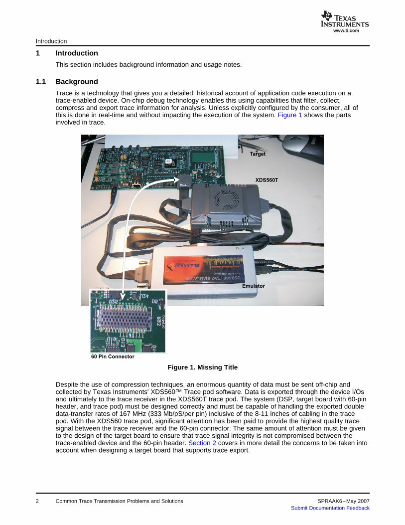
This section includes background information and usage notes.
Trace is a technology that gives you a detailed, historical account of application code execution on atrace-enabled device. On-chip debug technology enables this using capabilities that filter, collect,compress and export trace information for analysis. Unless explicitly configured by the consumer, all ofthis is done in real-time and without impacting the execution of the system. Figure 1 shows the partsinvolved in trace.
Figure 1. Missing Title
Despite the use of compression techniques, an enormous quantity of data must be sent off-chip andcollected by Texas Instruments' XDS560™ Trace pod software. Data is exported through the device I/Osand ultimately to the trace receiver in the XDS560T trace pod. The system (DSP, target board with 60-pinheader, and trace pod) must be designed correctly and must be capable of handling the exported doubledata-transfer rates of 167 MHz (333 Mb/pS/per pin) inclusive of the 8-11 inches of cabling in the tracepod. With the XDS560 trace pod, significant attention has been paid to provide the highest quality tracesignal between the trace receiver and the 60-pin connector. The same amount of attention must be givento the design of the target board to ensure that trace signal integrity is not compromised between thetrace-enabled device and the 60-pin header. Section 2 covers in more detail the concerns to be taken intoaccount when designing a target board that supports trace export.
2 Common Trace Transmission Problems and Solutions SPRAAK6–May 2007Submit Documentation Feedback

www.ti.com
1.2 Usage Notes
2 Board Design
2.1 Checklist for Board Design
2.2 Transmission Lines
Board Design
There are a few items of which you should be aware before bringing up Code Composer Studio™ -- evenbefore plugging the XDS560 trace pod into the 60-pin header. All of this information and troubleshootingtips appear in Section 5.
Improper board design can impact the signal quality of a high-speed bus like trace and even alower-speed bus like JTAG by introducing phenomena such as ringing, reflections, cross-talk, and voltagedrop. Techniques that can minimize these phenomena are discussed below.
Note: On-chip trace can generate a predefined pattern for export out of the device. Thesepatterns are used by the trace software to calibrate the XDS560 trace pod software uponstarting a trace session. If this calibration fails, it is likely to be an issue with the tracesignal integrity on the target board; however, even if the calibration passes, it is possiblethat a signal integrity issue still exists. It is imperative that the steps described inSection 2.1 be followed to characterize the EMU and TCK signal quality.
To characterize the EMU and TCK signal quality, use the following check list:
Table 1. Checklist for Board Design
√ No. Items to Check
1 If the target board being used or if the design of your new target board is based on the TMS320C6455 DSP Starter Kit(DSK), see Section 3 for known issues and recommendations.
2 If the target board being used or if the design of your new target board is based on the TMS320TCI6482 DSK, seeSection 3 for known issues and recommendations.
3 Validate signal quality of TCK as described in Section 2.4.1. Check for stubs and proper ac termination.
a TCK will be running after connecting to the target via Code Composer Studio.
4 Resolve any signal quality issues with TCK.
5 Validate signal quality of the EMU signals as described in Section 2.4.2. Check for stubs and proper series termination.
a EMU signal activity occurs during trace calibration. This can be used as a means of generating EMU signalactivity for analysis. Using the Tools → Trace → Control window in the Code Composer Studio, calibrationoccurs if you change the number of pins or Export clock rate and click Apply.
6 Resolve any signal quality issues with the EMU signals.
A transmission line has five fundamental parts:
• Driver• Driver Output Impedance (ZO(driver))• Series Termination, Impedance Matching Resistor• Load Impedance (ZL)• Receiver(s)
Two transmission line examples are discussed: point-to-point and multiple-destinations. In both examplesit is important to note that trace stubs should be minimized if absolutely required, or eliminated if not.
SPRAAK6–May 2007 Common Trace Transmission Problems and Solutions 3Submit Documentation Feedback

www.ti.com
EMU [n]
Receiver
ZL
R
ImpedanceMatchingResistor
Target Board XDS560TCable
SeriesTerminator
Z = 50T(emu) ΩZO(driver)
ZO(drive)
TCK
Receiver Receiver ReceiverZL
R
SeriesTermination
ImpedanceMatchingResistors
XDS560T Target Board
...
Z = 50T(TCK) Ω
Cable
2.3 Impedance Matching
Board Design
Figure 2 is an example of a point-to-point transmission line. The defining characteristic of a point-to-pointtransmission line is the single driver and a single receiver. All EMU signals require a point-to-pointtransmission line. See Section 2.4.2 for details about the series termination.
Figure 2. Point-To-Point Transmission Line
In some situations a single driver is required to drive multiple destinations. As illustrated in Figure 3, anexample of such a case is the JTAG TCK driver in a system with multiple devices in the JTAG scan chain.There are two important items to note when doing this:• First, stub lengths should be minimized. A stub encounters an impedance mismatch at the
high-impedance input of the receiver, causing reflections (see Section 2.3).• Second, the termination should be placed closest to the last receiver on the transmission line.
Figure 3. Transmission Line With Multiple Receivers
When an electrical signal passes from one medium (such as a PCB board) to another (such as the cablingon the XDS560 trace pod) any change in impedance results in a reflection back to the source. The loss ofenergy resulting from a reflection causes attenuation of the signal as it proceeds to its destination. Thereflection itself can result in ringing and jitter as it collides with other signals being generated by thesource.
When connecting to an XDS560 trace pod, the impedance that must be matched by the target board is 50Ω. The same 50-Ω impedance applies to XDS560 pods. For the target board, three components should beconsidered when looking at impedance matching:
• Output impedance of the I/O buffer• Impedance of the signal termination• Impedance of the PCB trace
4 Common Trace Transmission Problems and Solutions SPRAAK6–May 2007Submit Documentation Feedback

www.ti.com
2.3.1 TI C6000 Output Impedances
2.3.2 PCB Trace Impedance
2.4 Termination Techniques
2.4.1 TCK AC Termination
TCK
Receiver Receiver Receiver
RZ = 50O(TCK) Ω
XDS560T Target Board
C
Probe Here
...
Z = 50T(tck) Ω
Cabling
Board Design
The output impedance on the I/Os on all TI devices is given in the IBIS model made available through TI’swebsite (http://www.ti.com) [6]. For all existing C6x trace-enabled devices, the output impedance is 25 Ω.This means that an additional 25 Ω is needed on the EMU signals before they can be safely transmittedoff the PCB. The recommended means of accomplishing this is discussed in Section 2.4.
Table 2. Nominal Output Impedances for DebugSignals on TI Devices
Nominal Output Impedance of EMUDevice Pins (Zo[emu])
TMS320C6414/15/16 25 Ω
TMS320C6416T 25 Ω
TMS320DM642 25 Ω
TMS320C6455 25 Ω
TMS320TCI6482 25 Ω
For maximum signal integrity, the EMU signal traces on the PCB must be designed for 50-Ω impedance.All connectors and interface devices are also 50-Ω impedance.
A proper termination is critical to the performance of digital signals. Termination techniques available fordesigners include: Parallel, Thevinin, Series, and ac.[3] TI recommends the use of a Series termination onEMU signals and an ac termination on TCK. How these terminations are determined and analyzed with anoscilloscope is described in the subsections that follow.
An ac termination includes a resistor (R) and a capacitor (C). The ac terminations are frequently used toterminate a clock input and should always be placed as close as possible to the receiver. In situationswhere there are multiple receivers on TCK (i.e., multiple devices in the same JTAG scan-chain), the actermination should be placed as close to the last receiver as possible (see Figure 4).
The resistor value (R) should match the impedance of the transmission line (ZT(tck)). Choosing a capacitorvalue is more complicated and an incorrect value can result in ringing. The capacitor value should becarefully calculated based on the board design and requirements. Design equations are provided below tohelp aid determining the value of the capacitor to use [3].
Figure 4. TCK AC Termination
SPRAAK6–May 2007 Common Trace Transmission Problems and Solutions 5Submit Documentation Feedback

www.ti.com
( )R = Z = 50
T tck
W
( )
( )
C / 2.2 Z
o
C = Capacitor value
= Rise time of TCK
Z Transmission line impedance
T tck
= t *
t
=
2.4.1.1 Analyzing the TCK Signal With an Oscilloscope
Board Design
Equation 1. Calculating R Value in TCK AC Termination
Equation 2. Calculating C Value in TCK AC Termination
When analyzing the TCK signal, a high-impedance, low capacitance oscilloscope probe should be usedwith a minimum bandwidth of 1 GHz. The oscilloscope should be rated for a minimum of 1 GHz to provideadequate bandwidth for your analysis. Waveforms should be analyzed at the ac termination, ashighlighted in Figure 5. Figure 5 and Figure 6 represent properly and improperly ac terminated signals,respectively.
Note: Waveforms collected within this document were captured using a Tektronix TDS7245B2.5 GHz oscilloscope and P7225 probes.
Figure 5. Waveform of a Properly AC Terminated Signal
6 Common Trace Transmission Problems and Solutions SPRAAK6–May 2007Submit Documentation Feedback

www.ti.com
2.4.2 EMU Series Termination
Receiver
Target Board XDS560T
R
Probe Here
Z = 50T(emu) ΩZ = 25O(emu) Ω
Z =L ¥ Ω
EMU [n]
Cabling
R = Z - Z 50 25 25
T(emu) O(EMU)
= W - W = W
Board Design
Figure 6. Waveform of an Improperly AC Terminated Signal
To obtain the proper termination values you must select the proper resistor and capacitor values.Depending on the target design, traditional resistor-capacitor values are 51.1 Ω and a 3.3 – 15 pFcapacitor. If the target impedance varies from 50 Ω (not recommended), the component values may needadjusting to provide the best results.
The series termination, also known as a source termination, is a series resistor applied at the source endof a signal. A series termination should only be used on a point-to-point transmission lines, all EMUsignals should be routed point-to-point. The series termination resistor should be chosen so the value ofthe resistor (R) and the output impedance of the EMU pin I/O buffers (ZO[emu]) equal the impedance of thetransmission line (ZT[emu]). Figure 7 illustrates the probe point when analyzing a series termination line.
Figure 7. EMU Series Termination
As explained in Section 2.2, the values of ZO[emu] and ZT[emu] are known.
Equation 3. Calculating R Value in EMU Series Termination
It is recommended that all EMU signals be series-terminated with a 25-Ω resistor adjacent to the driverpin.
SPRAAK6–May 2007 Common Trace Transmission Problems and Solutions 7Submit Documentation Feedback

www.ti.com
2.4.2.1 Analyzing EMU Signals With an Oscilloscope
Board Design
When analyzing the EMU signals a high-impedance, low capacitance oscilloscope probe should be used.Waveforms should be analyzed at the receiver side of the series termination, as highlighted in Figure 7.Figure 8 and Figure 9 have been generated using this as an observation point and assuming a 3.3-V I/O.
Figure 8 illustrates the rising edge of an EMU signal with no impedance mismatch. This is the desiredwaveform. The ledge at the 50% point is caused by an expected reflection from the high-impedancetermination at the end of the XDS560 trace pod cable. A t1 of 4 ns represents the amount of time the EMUsignal takes to leave the probe position, arrive at the high-impedance termination, and return as areflection.
Figure 8. EMU Signal at Probe Point With Matched Impedance
8 Common Trace Transmission Problems and Solutions SPRAAK6–May 2007Submit Documentation Feedback

www.ti.com
Board Design
Figure 9 is an illustration of the rising edge of an EMU signal with an impedance mismatch. Theoutput-impedance of the driver plus the series termination is greater than the impedance of thetransmission line. In other words, ZO[emu] + R > ZT[emu]. In this case, a smaller series termination resistorshould be chosen.
Figure 9. EMU Signal at Probe Point With Impedance Mismatch
SPRAAK6–May 2007 Common Trace Transmission Problems and Solutions 9Submit Documentation Feedback

www.ti.com
Board Design
Figure 10 is another illustration of the rising and falling edge of an EMU signal with an impedancemismatch.
Figure 10. EMU Signal at Probe Point With Impedance Mismatch
Common Trace Transmission Problems and Solutions10 SPRAAK6–May 2007Submit Documentation Feedback

www.ti.com
3 Common Targets
3.1 TMS320C6455 DSK
3.1.1 Revision A, B
Common Targets
Revision A and B of the TMS320C6455 DSKs use TMS320C6455 revision 1.1 silicon, which has a knownTCK sensitivity issue [1]. Using devices with this issue is not ideal; however, the steps described belowimprove the quality of the signal so this issue can be avoided. There are also known issues with theTMS320C6455 DSK that impact the integrity of the TCK and EMU signals. These issues, along withworkarounds, are described in the subsection below. If you are using one of these DSKs it is importantthat you follow the recommendations described in Table 3 before attempting to use trace.
Table 3. TMS320C6455 DSK Revision A/B Recommendations
Problem Recommendation
Missing ac termination on TCK (R95 and C126 are not Populate R95 with a 100 Ω resistor and C126 with an 8.2- pFpopulated) capacitor.
Long trace stub on TCK to RTCK Cut the trace to RTCK as close to the junction point aspossible. (1)
Series termination resistor wrong value Replace R96 and R93 with a 22-Ω resistor each
Long trace stub on EMU0 and EMU1 Remove resistors R510 and R511.
Resistor on TVD too large (R91) Replace R91 with a 100-Ω resistor.
(1) The loopback capability of the XDS560 trace pod (described in Section 4.2.1) must be enabled after this change.
Note: All succeeding board revisions should be verified for design compliance.
SPRAAK6–May 2007 Common Trace Transmission Problems and Solutions 11Submit Documentation Feedback

www.ti.com
3.1.1.1 Revision C
Common Targets
The revision C DSK is similar (slightly different board trace layout) to the revision A and B DSKs exceptthat some revision C boards are delivered with TMX320C6455 revision 2.0 silicon that improve the TCKsensitivity issue described in Section 2.4.1.1. However, the board itself has the same issues present onrevision A/B as described in Table 4. Resistor R105 can be removed to eliminate the long trace stub onTCK to RTCK instead of cutting a trace on the board itself. In revision C boards R95, C126 are installed.Should the modifications not fully solve the identified problems it is recommended that the trace output bereconfigured for 10-bit trace (8 data and 2 clocks) instead of the default 12-bit trace (10 data and 2clocks). See Section 4.2.2 for the configuration of 10-bit trace.
In addition to the above modifications it is recommended that the following files be installed and used:
1. Code Composer Studio Configuration File: TCI6482_C6455_BHUSB560_Trace_TP.ccs. This file isintended to be used with a Blackhawk emulator. If a different emulator is used then the appropriateconfiguration file should be generated for the emulator used. The configuration file is located on the TIextranet and should be placed in the <CCSTUDIO_INSTALL>\drivers\import directory. During CodeComposer Studio setup – it is necessary to import this particular file.
2. Code Composer Studio GEL File: DSK6455_TP.gel. The gel file allows you to generate trace patternsto test signal integrity. This file is located on the TI extranet for use. Always perform a “Trace Offsequence when you are through running a trace pattern export test. The Gel file should be placed inthe <CCSTUDIO_INSTALL>\cc\gel directory. If the Code Composer Studio Setup is configuredproperly, this gel file will load automatically.
Table 4. TMS320C6455 DSK Revision C Recommendations
Problem Recommendation
Missing ac termination on TCK (R95 and C126 are not Populate R95 with a 100 Ω and C126 is 8.2 pFpopulated)
Long trace stub on TCK to RTCK Cut the trace to RTCK as close to the junction point as possible. (1)
Series termination resistor wrong value Replace R96 and R93 with a 22 Ω resistor each
Long trace stub on EMU0 and EMU1 Remove resistors R510 and R511.
Resistor on TVD too large (R91) Replace R91 with a 100 Ω resistor.
Reflections from RTCK net Remove R105
(1) Note that the loopback capability of the XDS560 trace pod (described in Section 4.2.1) must be enabled after this change.
Note: All succeeding board revisions should be verified for design compliance.
Common Trace Transmission Problems and Solutions12 SPRAAK6–May 2007Submit Documentation Feedback

www.ti.com
3.2 TMS320TCI6482
Common Targets
The TMS320TCI6482 target is typically supplied with a mezzanine card. See the TMS320TCI6482 DSPEMAC/MDIO Module Reference Guide (SPRUE12) for proper configuration. Current versions of theTMS320TCI6482 silicon have a known TCK sensitivity issue [1]. Using devices with this issue is not ideal;however, the steps described below improve the quality of the signal so this issue can be avoided. Thereare also known issues with the TMS320TCI6482 that impact the integrity of the TCK and EMU signals.These issues, along with workarounds, are described in the subsection below. If you are using one ofthese DSKs it is important that you follow the recommendations described in Table 5 before attempting touse trace.
Table 5. TMS320TCI6482 Revision Recommendations
Problem Recommendation
Missing ac termination on TCK (R95 and C126 are not Populate R95 with a 100 Ω and C126 is 8.2 pFpopulated)
Long trace stub on TCK to RTCK Cut the trace to RTCK as close to the junction point as possible. (1)
Series termination resistor wrong value Replace R96 and R93 with a 22-Ω resistor each
Long trace stub on EMU0 and EMU1 Remove resistors R510 and R511
Resistor on TVD too large (R91) Replace R91 with a 100-Ω resistor
Reflections from RTCK net Remove R105
(1) Note that the loopback capability of the XDS560 trace pod (described in Section 4.2.1) must be enabled after this change.
In addition to the above modifications it is recommended that the following files be installed and used:
1. Code Composer Studio Configuration File: TCI6482_C6455_BHUSB560_Trace_TP.ccs. This file isintended to be used with a Blackhawk emulator. If a different emulator is used then the appropriateconfiguration file should be generated for the emulator used. The configuration file is located on the TIextranet and should be placed in the <CCSTUDIO_INSTALL>\drivers\import directory. During CodeComposer Studio setup it is necessary to import this particular file.
2. Code Composer Studio GEL File: DSK6455_TP.gel (see Note below). The gel file allows you togenerate trace patterns to test signal integrity. This file is located on the TI extranet for use. Alwaysperform a Trace Off sequence when you are through running a trace pattern export test. The Gel fileshould be placed in the <CCSTUDIO_INSTALL>\cc\gel directory. If Code Composer Studio Setup isconfigured properly this gel file will load automatically.
Note: The GEL file has been combined with the TMS320C6455 GEL file.
SPRAAK6–May 2007 Common Trace Transmission Problems and Solutions 13Submit Documentation Feedback

www.ti.com
3.3 TMS320C6416 DSK
3.3.1 Revision D
3.3.2 Enabling 10-Bit Trace
Common Targets
Note: Trace is not supported on order TMS320C6416 DSK’s incorporating Rev. 1.0 silicon.
Revision D of the TMS320C6416 DSKs uses TMS320C6416 revision 1.1 silicon. This is the only knowngood version of the C6416 silicon available to date. Excessive trace lengths, primarily on EMU0 andEMU1 create reflections that are unacceptable when operating at the trace export frequency. Modificationson the C6416 DSK are extensive and require a significant amount of physical work to the board. Therecommendations are identified in the following subsection and in the C6416 DSK ECN-001. It is stronglyrecommended that the ECN not be implemented and instead the trace output be reconfigured for 10-bittrace (8 data and 2 clocks) instead of the default 12-bit trace (10 data and 2 clocks). See Section 3.3.2 forthe configuration of 10-bit trace.
In addition to the above modifications it is recommended that the following files be installed and used:
1. Code Composer Studio Configuration File: BH-USB560m_c64xx_11_TP.ccs. This file is intended to beused with a Blackhawk emulator. If a different emulator is used then the appropriate configuration fileshould be generated for the emulator used. The configuration file is located on the TI extranet andshould be placed in the <CCSTUDIO_INSTALL>\drivers\import directory. During Code ComposerStudio setup it is necessary to import this particular file.
2. Code Composer Studio GEL File: dsp641x_TP.gel. The gel file allows you to generate trace patternsto test signal integrity. This file is located on the TI extranet for use. Always perform a Trace Offsequence when you are through running a trace pattern export test. The Gel file should be placed inthe <CCSTUDIO_INSTALL>\cc\gel directory. If Code Composer Studio Setup is configured properlythis gel file will automatically load.
Table 6. TMS320C6416 DSK Trace Modifications
Problem Recommendation
Excessive reflections on EMU0 and EMU1 Cut EMU0 and EMU1 nets on PCB per ECN -001
To disable the 12-bit trace within Code Composer Studio and enable 10-bit trace, the following proceduresshould be used:
Step 1. Start Code Composer Studio, and load your application.Step 2. From the Tools→Trace→Control.Step 3. From the Control window select 10-bit trace.Step 4. Depress the Apply button.Step 5. Close all completed windows not needed.Step 6. Operate trace as originally planned.
Common Trace Transmission Problems and Solutions14 SPRAAK6–May 2007Submit Documentation Feedback

www.ti.com
4 Usage Notes
4.1 Special Note on Connecting the 60-Pin Emulator to Target
4.2 TMS320C6455
4.2.1 Enabling XDS560 Trace Pod TCK Loopback Feature
4.2.2 Enabling 10 Bit Trace
Usage Notes
Care should be exercised when connecting to the high-density 60-pin emulation header. The connectorselected is a high density connector of the highest quality available. Please use caution when insertingand removing the emulator connector to the target board connector and never force the emulatorconnector onto the target connector. The connector, when inserted correctly, will seat fully. A minimumamount of force is required to make a proper connection. If excessive force is required or the mated pairdo not fully seat it is possible that a pin has been bent. Use extreme care when attempting to straighten apin. You can permanently damage the connector and emulator if not handled properly. Always examinethe target connector and emulator connector prior to mating the two.
The TMS320C6455 device has a sensitive TCK input buffer that makes the device prone to failure bycapturing false edges from the TCK signal. The issue is described in detail in the TMS320C6455/54 DigitalSignal Processor Silicon Errata (Silicon Revs 2.0, 1.1) (literature number SPRZ234) [1].
As mentioned in the errata, you can work around the problem by ensuring proper board design (describedin Section 2), and by using a loopback capability built into the XDS560 trace pod. TCK loopback uses adedicated buffer in the XDS560 trace pod connector to drive the RTCK back to the emulator directly fromthe TCK source, effectively ignoring the RTCK signal on the 60-pin header.
The TMS320C6455 modifications may not solve all problems (depending on target design andtolerances). Should the modifications not fully solve the identified problems it is recommended that thetrace output be reconfigured for 10-bit trace (8 data and 2 clocks) instead of the default 12-bit trace (10data and 2 clocks). See Section 4.2.2 for the configuration of 10-bit trace.
To enable the loopback feature, follow the steps provided in the section below.
Code Composer Studio Setup can be used to enable the XDS560 trace pod loopback feature for theC6455 device. To do this:
Step 1. Select the Auto-generate board data file with extra configuration file option in your board’sConnection Properties window
Step 2. Specify the xds560tracepod.cfg file located in your <CCSTUDIO_INSTALL>\cc\bin\BrdDat"directory as the Configuration File.
To disable the 12-bit trace within Code Composer Studio and enable 10-bit trace the following proceduresshould be followed.
Step 1. Start Code Composer Studio, and loading your applicationStep 2. From the Tools→Trace→ControlStep 3. From the Control window, select 10-bit traceStep 4. Depress the Apply buttonStep 5. Close all completed windows not neededStep 6. Operate trace as originally planned
SPRAAK6–May 2007 Common Trace Transmission Problems and Solutions 15Submit Documentation Feedback

www.ti.com
4.3 TMS320TCI6482
4.3.1 Enabling XDS560 Trace Pod TCK Loopback Feature
4.3.2 Enabling 10 Bit Trace
5 Troubleshooting
5.1 Code Composer Studio Disconnects From the Device When Running With Trace Enabled
5.2 Receiving Bad Data
Troubleshooting
The TMS320TCI6482 device has a sensitive TCK input buffer that makes the device prone to failure bycapturing false edges from the TCK signal. The issue is described in detail in the Silicon Errata of theTMS320TCI6482 [2].
As mentioned in the errata, the work around for this problem is by ensuring proper board design and byusing a loopback capability built into the XDS560 trace pod. TCK loopback uses a dedicated buffer in theXDS560 trace pod connector to drive the RTCK back to the emulator directly from the TCK source,effectively ignoring the RTCK signal on the 60-pin header.
The TMS320TCI6482 modifications may not solve all problems (depending on target design andtolerances). Should the modifications not fully solve the identified problems, it is recommended that thetrace output be reconfigured for 10-bit trace (8 data and 2 clocks) instead of the default 12-bit trace (10data and 2 clocks). See Section 4.3.2 for the configuration of 10-bit trace.
To enable the loopback feature, follow the steps provided in Section 4.3.1.
Code Composer Studio setup can be used to enable the XDS560 trace pod loopback feature for theTCI6482 device. To do this:
Step 1. Select the Auto-generate board data file with extra configuration file option in your board’sConnection Properties window
Step 2. Specify the xds560tracepod.cfg file located in your <CCSTUDIO_INSTALL>\cc\bin\BrdDat”directory as the Configuration File
To disable the 12-bit trace within Code Composer Studio and enable the 10-bit trace, the followingprocedures should be followed.
Step 1. Start Code Composer Studio and load your applicationStep 2. From the Tools→Trace→ControlStep 3. From the Control window select 10-bit traceStep 4. Depress the Apply buttonStep 5. Close all completed windows not neededStep 6. Operate trace as originally planned
This section aids you in troubleshooting common issues that may be related to electrical issues. Onlinehelp, accessible through the Trace Display and Trace Control menus in the Code Composer Studio,should be utilized to troubleshoot issues not discussed in this section.
If you are using a TMS320C6455 or TMS320TCI6482 and you encounter a Code Composer Studiodisconnect when running with trace turned on, it is likely you are encountering the issues described inSection 4.2 or Section 4.3. Verify that the loopback mode has been turned on and the checks described inSection 2.1 have been performed.
A Bad Data warning may be generated in the Trace Display window for a number of reasons, including:
• Application code includes self-modifying code• Erroneous trace data recorded because of transmission line problems (e.g., reflections)
To detect a transmission line problem, the first step to take is to be sure the checks described in
16 Common Trace Transmission Problems and Solutions SPRAAK6–May 2007Submit Documentation Feedback

www.ti.com
5.3 Pod Error/Pod Setup Error
5.4 Known Software Issues
5.4.1 Code Composer Studio Crashes
Troubleshooting
Section 2.1 have been performed. In the past there have been specific issues with the EMU0 and EMU1signals on certain boards, so they should be looked at specifically. If there is an issue with the EMU0 andEMU1 signals but not the others, then you can remove the dependency on these pins by configuring traceto be exported over 10 pins instead of the default 12. This can be performed using the Trace Controlwindow.
If signal looks good, the second thing to try is to lower the Trace Export Clock Rate through the TraceControl window.
The online help for trace should be referenced for additional information related to receiving a Bad Datawarning message.
Errors encountered during the trace calibration process may indicate an electrical or mechanical problem.Some of the more common calibration errors are described:
Pod Setup Error - Low frequency DAC adjust failed
Description The trace calibration process tests across all signal threshold DAC values at the lowestfrequency possible. If no good values are found, this error terminates the trace calibrationprocess.
Cause This error may indicate the trace pod target cable is not seated properly or an electricalproblem with the target’s EMU signals.
Pod Setup Error - Skew adjust failed
Description The calibration process failed during skew adjust.
Cause This error probably indicates an electrical problem with the target’s EMU signals.
Pod Error - Less than half a nanosecond of sampling margin detected
Description The calibration process failed during skew adjust.
Cause This error probably indicates an electrical problem with the target’s EMU signals.
A list of known software issues is provided in the product release notes [5]. If a software issue isencountered that is not listed, it is recommended that a defect report be filed per the instructions alsodescribed in the product release notes.
There are no known issues that should cause the Code Composer Studio application to unexpectedly exit.However, if this were to occur then it is possible you may have trace software running in the backgrounderroneously. Using the Windows® Task Manager, search for and terminate any traceserver.exe,tracecntrl.exe, tracedisplay.exe and tracecompmgr.exe processes that may be running.
SPRAAK6–May 2007 Common Trace Transmission Problems and Solutions 17Submit Documentation Feedback

www.ti.com
6 Glossary
7 References
Glossary
AC Termination —The ac termination comprises a resistor, R, and a capacitor, C, that connect to theload end of the transmission line.
Reflections — Reflections are the result of an impedance mismatch in electrical signals. When voltagehits a discontinuity, some energy is reflected. This occurs in any change in a material's final stop(connection to another material). [3], [4]
Series Termination —Series termination is a source-end termination unlike other types. A seriestermination comprises a resistor between the driver's output and the line.
1. TMS320C6455/54 Digital Signal Processor Silicon Errata (Silicon Revs 2.0, 1.1) (SPRZ234)2. TMS320TCI6482 Digital Signal Processor Silicon Errata (Silicon Revs 2.0, 1.1) (SPRZ235)3. Ethirajan K, Nemec J, Termination Techniques for High-Speed Buses, EDN Design Feature4. 60-Pin Emulation Header Technical Reference (SPRU655)5. XDS560 Trace v0.1.0 Beta Release Notes (SPRA377)6. www.ti.com -- Texas Instruments website
18 Common Trace Transmission Problems and Solutions SPRAAK6–May 2007Submit Documentation Feedback

IMPORTANT NOTICE
Texas Instruments Incorporated and its subsidiaries (TI) reserve the right to make corrections, modifications, enhancements,improvements, and other changes to its products and services at any time and to discontinue any product or service without notice.Customers should obtain the latest relevant information before placing orders and should verify that such information is current andcomplete. All products are sold subject to TI’s terms and conditions of sale supplied at the time of order acknowledgment.
TI warrants performance of its hardware products to the specifications applicable at the time of sale in accordance with TI’sstandard warranty. Testing and other quality control techniques are used to the extent TI deems necessary to support thiswarranty. Except where mandated by government requirements, testing of all parameters of each product is not necessarilyperformed.
TI assumes no liability for applications assistance or customer product design. Customers are responsible for their products andapplications using TI components. To minimize the risks associated with customer products and applications, customers shouldprovide adequate design and operating safeguards.
TI does not warrant or represent that any license, either express or implied, is granted under any TI patent right, copyright, maskwork right, or other TI intellectual property right relating to any combination, machine, or process in which TI products or servicesare used. Information published by TI regarding third-party products or services does not constitute a license from TI to use suchproducts or services or a warranty or endorsement thereof. Use of such information may require a license from a third party underthe patents or other intellectual property of the third party, or a license from TI under the patents or other intellectual property of TI.
Reproduction of information in TI data books or data sheets is permissible only if reproduction is without alteration and isaccompanied by all associated warranties, conditions, limitations, and notices. Reproduction of this information with alteration is anunfair and deceptive business practice. TI is not responsible or liable for such altered documentation.
Resale of TI products or services with statements different from or beyond the parameters stated by TI for that product or servicevoids all express and any implied warranties for the associated TI product or service and is an unfair and deceptive businesspractice. TI is not responsible or liable for any such statements.
TI products are not authorized for use in safety-critical applications (such as life support) where a failure of the TI product wouldreasonably be expected to cause severe personal injury or death, unless officers of the parties have executed an agreementspecifically governing such use. Buyers represent that they have all necessary expertise in the safety and regulatory ramificationsof their applications, and acknowledge and agree that they are solely responsible for all legal, regulatory and safety-relatedrequirements concerning their products and any use of TI products in such safety-critical applications, notwithstanding anyapplications-related information or support that may be provided by TI. Further, Buyers must fully indemnify TI and itsrepresentatives against any damages arising out of the use of TI products in such safety-critical applications.
TI products are neither designed nor intended for use in military/aerospace applications or environments unless the TI products arespecifically designated by TI as military-grade or "enhanced plastic." Only products designated by TI as military-grade meet militaryspecifications. Buyers acknowledge and agree that any such use of TI products which TI has not designated as military-grade issolely at the Buyer's risk, and that they are solely responsible for compliance with all legal and regulatory requirements inconnection with such use.
TI products are neither designed nor intended for use in automotive applications or environments unless the specific TI productsare designated by TI as compliant with ISO/TS 16949 requirements. Buyers acknowledge and agree that, if they use anynon-designated products in automotive applications, TI will not be responsible for any failure to meet such requirements.
Following are URLs where you can obtain information on other Texas Instruments products and application solutions:
Products Applications
Amplifiers amplifier.ti.com Audio www.ti.com/audio
Data Converters dataconverter.ti.com Automotive www.ti.com/automotive
DSP dsp.ti.com Broadband www.ti.com/broadband
Interface interface.ti.com Digital Control www.ti.com/digitalcontrol
Logic logic.ti.com Military www.ti.com/military
Power Mgmt power.ti.com Optical Networking www.ti.com/opticalnetwork
Microcontrollers microcontroller.ti.com Security www.ti.com/security
Low Power www.ti.com/lpw Telephony www.ti.com/telephonyWireless
Video & Imaging www.ti.com/video
Wireless www.ti.com/wireless
Mailing Address: Texas Instruments, Post Office Box 655303, Dallas, Texas 75265Copyright © 2007, Texas Instruments Incorporated