Embed Size (px)
Citation preview

CHAPTER 2
Communicating over the Network
Objectives
Upon completion of this chapter, you will able to
answer the following questions:
■ What is the structure of a network, including
devices and media necessary for communications?
■ What function do protocols perform in network
communications?
■ What are the advantages of using a layered
model to describe network functionality?
■ What is the role of each layer in the OSI
network model and the TCP/IP network model?
■ What is the importance of addressing and
naming schemes in network communications?
Key Terms
This chapter uses the following key terms. You can find the definitions in the Glossary.
channel page 35
segmentation page 35
multiplexing page 36
switch page 37
end device page 37
host page 37
client page 37
host address page 38
physical address page 38
intermediary device page 38
encoding page 39
local-area network (LAN) page 41
Internet service provider (ISP) page 42
protocols page 44
protocol suite page 45
Institute of Electrical and Electronics Engineers
(IEEE) page 46
Internet Engineering Task Force (IETF) page 46
layered models page 47
TCP/IP page 48
encapsulation page 51
decapsulation page 51
protocol data unit (PDU) page 51
segment page 51
frame page 51
Open Systems Interconnection (OSI) page 53
International Organization for Standardization (ISO)
page 53
port page 57

More and more, networks connect us. People communicate online from everywhere.
Efficient, dependable technology enables networks to be available whenever and wherever
we need them. As the human network continues to expand, the platform that connects and
supports it must also grow.
Rather than developing unique and separate systems for the delivery of each new service,
the network industry as a whole has developed the means to both analyze the existing plat-
form and enhance it incrementally. This ensures that existing communications are main-
tained while new services are introduced that are both cost effective and technologically
sound.
This book focuses on these aspects of the information network:
■ Devices that make up the network
■ Media that connect the devices
■ Messages that are carried across the network
■ Rules and processes that govern network communications
■ Tools and commands for constructing and maintaining networks
Central to the study of networks is the use of generally accepted models that describe network
functions. These models provide a framework for understanding current networks and for
facilitating the development of new technologies to support future communications needs.
Within this book, you learn about these models and the tools designed to analyze and simu-
late network functionality. Two of the tools that will enable you to build and interact with
simulated networks are Packet Tracer 4.1 software and Wireshark network protocol analyzer.
In this chapter, you explore the fundamentals of communication and learn how they apply
to communication in and between data networks. You also learn about two important mod-
els that describe the process of network communication and the devices used to achieve
communication between network hosts.
The Platform for Communications
Networks are becoming the foundation to human communication over distance. In the past
decade or so, personal letters have become e-mails, typed and handwritten documents have
become word processing files, photographs have become digital, and phone calls are mov-
ing from analog to digital. This transformation to a digital platform is possible because
computer networks have grown in size, reliability, and diversity, enabling people to take
advantage of the benefits of digital communication. The following sections focus on the
platform for this digital communication that is built upon fundamental communication con-
cepts. These concepts are applied to devices and media that enable the sending of data mes-
sages between end users.
34 Network Fundamentals, CCNA Exploration Companion Guide
The Elements of Communication
People exchange ideas using many different communication methods. All of these methods
have three elements in common:
■ Message source, or sender: Message sources are people, or electronic devices, that
need to send a message to other individuals or devices.
■ Destination, or receiver of the message: The destination receives the message and
interprets it.
■ Channel: A channel consists of the media that provides the pathway over which the
message can travel from source to destination.
This model of sending a message through a channel to the receiver is also the basis of net-
work communication between computers. The computers encode the message into binary
signals and transport them across a cable or through wireless media to the receiver, which
knows what rules to follow to understand the original message.
The basic model of communication between people and between computers is illustrated in
Figure 2-1.
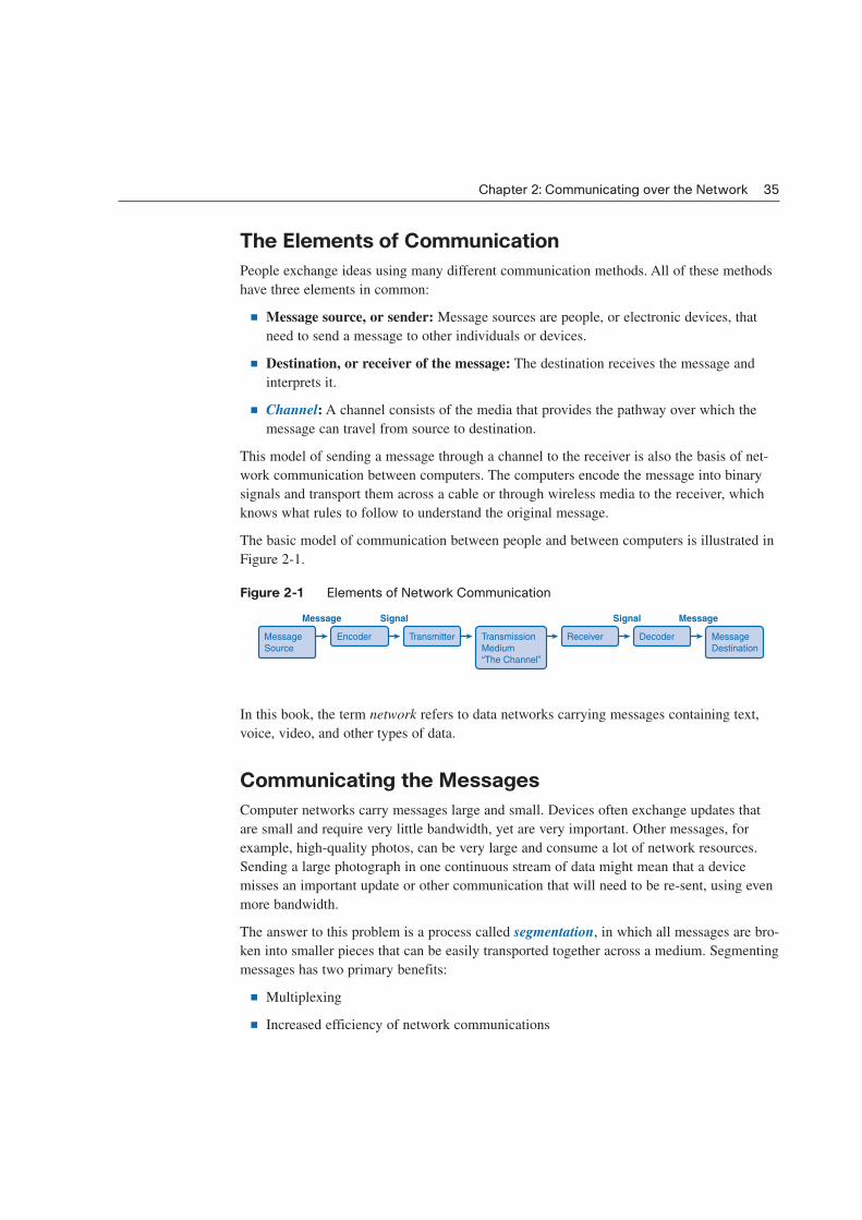
Figure 2-1 Elements of Network Communication
In this book, the term network refers to data networks carrying messages containing text,
voice, video, and other types of data.
Communicating the Messages
Computer networks carry messages large and small. Devices often exchange updates that
are small and require very little bandwidth, yet are very important. Other messages, for
example, high-quality photos, can be very large and consume a lot of network resources.
Sending a large photograph in one continuous stream of data might mean that a device
misses an important update or other communication that will need to be re-sent, using even
more bandwidth.
The answer to this problem is a process called segmentation, in which all messages are bro-
ken into smaller pieces that can be easily transported together across a medium. Segmenting
messages has two primary benefits:
■ Multiplexing
■ Increased efficiency of network communications
Chapter 2: Communicating over the Network 35
Encoder
Message Signal MessageSignal
Message
Source
Transmission
Medium
“The Channel”
Transmitter DecoderReceiver Message
Destination

Multiplexing occurs when the segments of two or more messages can shuffle into each
other and share the medium. Figure 2-2 depicts how messages can be broken into smaller
pieces and multiplexed onto a single medium.
Figure 2-2 Multiplexing Messages on a Network
A second benefit of segmentation is that networks can more efficiently send the message
through different routes if necessary. This can happen because the Internet is always adjust-
ing routes for efficiency. For example, consider what happens if someone in Las Vegas
e-mails a picture of her new kitten to a friend in Boston. First, the picture of the kitten is
segmented into small pieces and each piece is given, among other things, a destination
address and a code telling where the piece belongs in the big picture. When the message is
under way, the pieces might not travel along the same route. Traffic conditions on the
Internet are constantly changing, and a large file with many segments can take a couple dif-
ferent routes. Depending on traffic conditions, the data containing the kitten’s ears might go
through Chicago on the way to Boston, the paws might go through Denver, and the
whiskers and tail might travel through Atlanta. It doesn’t matter which way the pieces travel
as long as they all get to Boston and the destination computer can reassemble them into one
photograph.
The downside to using segmentation and multiplexing to transmit messages across a net-
work is the level of complexity that is added to the process. Imagine if you had to send a
100-page letter, but each envelope would hold only one page. The process of addressing,
labeling, sending, receiving, and opening the entire hundred envelopes would be time con-
suming for both the sender and the recipient.
In network communications, each segment of the message must go through a similar
process to ensure that it gets to the correct destination and can be reassembled into the con-
tent of the original message.
Various types of devices throughout the network participate in ensuring that the pieces of
the message arrive reliably at their destination.
36 Network Fundamentals, CCNA Exploration Companion Guide
Multiple communications are interleaved,
giving each user a part of the bandwidth.
Multiplexing—
Interleaving the pieces as
they traverse the media.

Components of the Network
The path that a message takes from source to destination can be as simple as a single cable
connecting one computer to another or as complex as a network that literally spans the
globe. This network infrastructure is the platform that supports our human network. It pro-
vides the stable and reliable channel over which our communications can occur.
Devices and media are the physical elements or hardware of the network. Hardware is often
the visible components of the network platform such as a laptop, a PC, a switch, or the
cabling used to connect the devices. Occasionally, some components might not be so visi-
ble. In the case of wireless media, messages are transmitted through the air using invisible
radio frequency or infrared waves.
Services and processes are the communication programs, called software, that run on the
networked devices. A network service provides information in response to a request.
Services include many of the common network applications people use every day, like
e-mail hosting services and web hosting services. Processes provide the functionality that
directs and moves the messages through the network. Processes are less obvious to us but
are critical to the operation of networks.
End Devices and Their Role on the Network
An end device refers to a piece of equipment that is either the source or the destination of a
message on a network. Network users usually only see and touch an end device, which is
most often a computer. Another generic term for an end device that sends or receives mes-
sages is a host. A host can be one of several pieces of equipment performing a wide variety
of functions. Examples of hosts and end devices are as follows:
■ Computers, including workstations, laptops, and servers connected to a network
■ Network printers
■ Voice over Internet Protocol (VoIP) phones
■ Cameras on a network, including webcams and security cameras
■ Handheld devices such as PDAs and handheld scanners
■ Remote monitoring stations for weather observation
An end user is a person or group using an end device. Not all end devices are operated by
people all of the time, though. For example, file servers are end devices that are set up by
people but perform their tasks on their own. Servers are hosts that are set up to store and
share information with other hosts called clients. Clients request information and services,
like e-mail and web pages, from servers, and servers reply with the requested information if
they recognize the client.
Chapter 2: Communicating over the Network 37
When hosts communicate with each other, they use addresses to find each other. The host
address is a unique physical address used by hosts inside a local-area network (LAN), and
when a host sends a message to another host, it uses the physical address of the destination
device.
Intermediary Devices and Their Role on the Network
End devices are the hosts that initiate communications and are the ones that people are most
familiar with. But getting a message from the source to the destination can be a complex
task involving several intermediary devices along the way. Intermediary devices connect the
individual hosts to the network and can connect multiple individual networks to form an
internetwork.
Intermediary devices are not all the same. Some work inside the LAN performing switching
functions, and others help route messages between networks. Table 2-1 lists some interme-
diary devices and their functions.
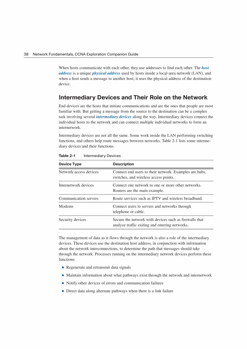
Table 2-1 Intermediary Devices
Device Type Description
Network access devices Connect end users to their network. Examples are hubs,
switches, and wireless access points.
Internetwork devices Connect one network to one or more other networks.
Routers are the main example.
Communication servers Route services such as IPTV and wireless broadband.
Modems Connect users to servers and networks through
telephone or cable.
Security devices Secure the network with devices such as firewalls that
analyze traffic exiting and entering networks.
The management of data as it flows through the network is also a role of the intermediary
devices. These devices use the destination host address, in conjunction with information
about the network interconnections, to determine the path that messages should take
through the network. Processes running on the intermediary network devices perform these
functions:
■ Regenerate and retransmit data signals
■ Maintain information about what pathways exist through the network and internetwork
■ Notify other devices of errors and communication failures
■ Direct data along alternate pathways when there is a link failure
38 Network Fundamentals, CCNA Exploration Companion Guide

■ Classify and direct messages according to quality of service (QoS) priorities
■ Permit or deny the flow of data, based on security settings
Figure 2-3 depicts two LANs with end devices connected by intermediary switches in the
LANs and routers between the LANs.
Figure 2-3 LANs Connected by Routers
Network Media
Communication across a network is carried on a medium. The medium provides the chan-
nel over which the message travels from source to destination. The three main types of
media in use in a network are
■ Copper
■ Fiber-optic cable
■ Wireless
Each of these media has vastly different physical properties and uses different methods to
encode messages. Encoding messages refers to the way data is converted to patterns of
electrical, light, or electromagnetic energy and carried on the medium. Each medium is
briefly described in Table 2-2.
Chapter 2: Communicating over the Network 39
LAN LAN
Internetwork

Table 2-2 Networking Media
Media Example Encoding
Copper Twisted-pair cable usually Electrical pulses
used as LAN media
Fiber-optic Glass or plastic fibers in a vinyl coating Light pulses
usually used for long runs in a LAN
and as a trunk
Wireless Connects local users through the air Electromagnetic waves
The differences in the media make each one ideal for different roles in networking situa-
tions. When choosing network media, administrators must consider the following:
■ The distance the media can carry the signal
■ The environment in which the media works
■ The bandwidth requirements for users
■ The cost of installation
■ The cost of connectors and compatible equipment
Fiber, copper, and wireless media are shown in Figure 2-4.
Figure 2-4 Network Media
40 Network Fundamentals, CCNA Exploration Companion Guide
Copper
Fiber Optics
Wireless
LANs, WANs, and Internetworks
Networks come in many sizes and serve a wide variety of functions. Following are some of
the basic differences:
■ The size of the area covered
■ The number of users connected
■ The number and types of services available
Three distinct groups of networks accommodate different groups and extend geographic
boundaries: local-area networks (LANs), wide-area networks (WANs), and internetworks.
Local-Area Networks
A local-area network (LAN) is a group of end devices and users under the control of a
common administration. The term local first meant that the computers were grouped geo-
graphically close together and had the same purpose in an organization. This is still true in
many situations, but as technologies evolve, the definition of local has evolved as well. A
LAN can consist of one group of users on one floor, but the term can also be used to
describe all users on a multibuilding campus.
Wide-Area Networks
A wide-area network (WAN) is a network that is used to connect LANs that are located
geographically far apart. If a company has offices in different cities, it will contract with a
telecommunications service provider (TSP) to provide data lines between LANs in each
city. The leased lines will vary in service and bandwidth, depending on the terms of the
contract. The TSP is responsible for the intermediary devices on the WAN that transports
messages, while LANs at both ends are controlled by the company. The sole purpose of
WANs is to connect LANs, and there are usually no end users on WANs. Figure 2-5 depicts
two LANs connected by a WAN.
Chapter 2: Communicating over the Network 41
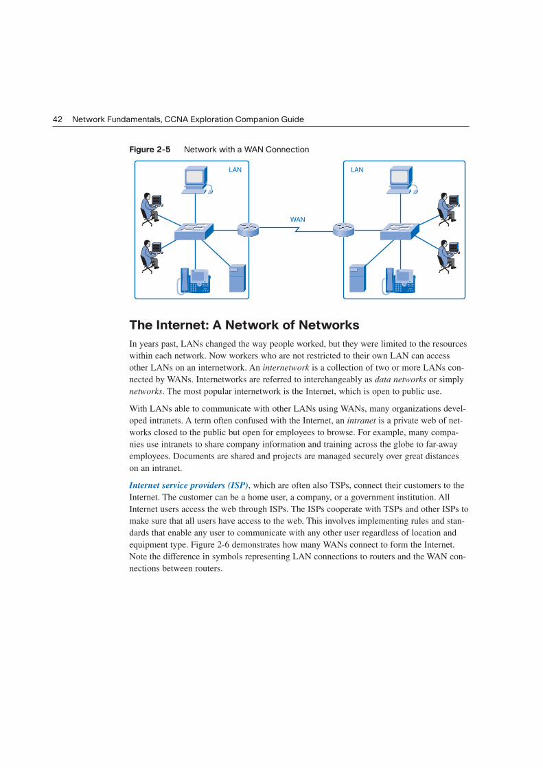
Figure 2-5 Network with a WAN Connection
The Internet: A Network of Networks
In years past, LANs changed the way people worked, but they were limited to the resources
within each network. Now workers who are not restricted to their own LAN can access
other LANs on an internetwork. An internetwork is a collection of two or more LANs con-
nected by WANs. Internetworks are referred to interchangeably as data networks or simply
networks. The most popular internetwork is the Internet, which is open to public use.
With LANs able to communicate with other LANs using WANs, many organizations devel-
oped intranets. A term often confused with the Internet, an intranet is a private web of net-
works closed to the public but open for employees to browse. For example, many compa-
nies use intranets to share company information and training across the globe to far-away
employees. Documents are shared and projects are managed securely over great distances
on an intranet.
Internet service providers (ISP), which are often also TSPs, connect their customers to the
Internet. The customer can be a home user, a company, or a government institution. All
Internet users access the web through ISPs. The ISPs cooperate with TSPs and other ISPs to
make sure that all users have access to the web. This involves implementing rules and stan-
dards that enable any user to communicate with any other user regardless of location and
equipment type. Figure 2-6 demonstrates how many WANs connect to form the Internet.
Note the difference in symbols representing LAN connections to routers and the WAN con-
nections between routers.
42 Network Fundamentals, CCNA Exploration Companion Guide
LAN LAN
WAN

Figure 2-6 Internetworks Made Up of LANs and WANs
Network Representations
Chapter 1, “Living in a Network-Centric World,” introduced many common data network
symbols pictured in Figure 2-7. When discussing how devices and media connect to each
other, remember these important terms:
■ Network interface card (NIC): A NIC, or LAN adapter, provides the physical connec-
tion to the network at the PC or other host device. The media connecting the PC to the
networking device plugs directly into the NIC. Each NIC has a unique physical address
that identifies it on the LAN.
■ Physical port: A physical port is a connector or outlet on a networking device where
the media is connected to a host or other networking device. You can assume that all
network host devices used in this book have a physical port that allows a connection to
the network.
■ Interface: The term interface refers to how the device can allow two different net-
works to communicate. Routers connect to different networks, and the specialized
NICs on routers are simply called interfaces. The interface on a router device has a
unique physical address and appears as a host on the local network.
Chapter 2: Communicating over the Network 43
Internet

Figure 2-7 Network Device and Media Symbols
Network Representations (2.2.4.2)
In this activity, you will gain experience with data network symbols by creating a simple
logical topology. Use file e1-2242.pka on the CD-ROM that accompanies this book to per-
form this activity using Packet Tracer.
Protocols
All communication, whether face-to-face or over a network, is governed by predetermined
rules called protocols. These protocols are specific to the characteristics of the conversation.
Network communication follows protocols similar to those used in human communication.
Rules That Govern Communications
Protocols are rules used by anyone who communicates with another. During a conversation,
people usually don’t think about protocols until someone breaks one, but many levels of
behavior are important for successful communication. For example, the clothing and infor-
mal language that is appropriate when you’re with your close friends is not appropriate in a
44 Network Fundamentals, CCNA Exploration Companion Guide
Desktop
Computer
Cloud
LAN
Media
WAN
Media
Wireless
Media
Router
Laptop
Server
IP Phone LAN Switch
Wireless
Router
Firewall
Packet Tracer
Activity
formal setting with a court official. Being improperly dressed for the communication situa-
tion could derail the message before any words are spoken. Also, people who interrupt con-
versations, speak too loudly, or walk away from conversations without the proper closing
words like “thank you” or “good-bye” are considered rude, and the rude behavior can dis-
tract from the importance of the message. In addition, if a person tries to communicate in a
language that the receiver does not understand, attempts at verbal communication will likely
fail.
The protocols in human communication are separate rules about appearance, speaking,
listening, and understanding. All these rules, also called protocols of conversation, represent
different layers of communication. They work together to help people successfully
communicate.
You can use these examples to understand three different layers of a simple conversation.
Consider two people communicating face to face. The bottom layer, the physical layer, has
two people, each with a voice that can utter words aloud. The second layer, the rules layer,
has an agreement to speak in a common language. The top layer, the content layer, has the
words actually spoken, that is, the content of the communication.
Were you to witness this conversation, you would not see the layers. It is important to
understand that the use of layers is a model and, as such, layers provide a way to conve-
niently break a complex task into parts and describe how they work.
The need for protocols also applies to network devices. Computers have no way of learning
protocols, so network engineers have written rules for communication that must be strictly
followed for successful host-to-host communication. These rules apply to different layers of
sophistication such as which physical connections to use, how hosts listen, how to interrupt,
how to say good-bye, what language to use, and many others. These rules, or protocols, that
work together to ensure successful communication are grouped into what is known as a pro-
tocol suite.
Network Protocols
For devices to communicate on a network, they must follow different protocols that perform
the many tasks to be completed. The protocols define the following:
■ The format of the message, such as how much data to put into each segment
■ The way intermediary devices share information about the path to the destination
■ The method to handle update messages between intermediary devices
■ The process to initiate and terminate communications between hosts
Chapter 2: Communicating over the Network 45

The authors of the protocols might be writing them for a specific company that will own the
protocol. The protocol is treated like a copyright and can be licensed to other companies to
use. Protocols controlled by a company and not for public use are considered proprietary.
Other protocols are written for public use at no charge and are considered open source
protocols.
Protocol Suites and Industry Standards
In the early days of networking, each manufacturer had proprietary network equipment and
protocols to support it. This worked well as long as the company that purchased the equipment
did not need to share data outside its own network. As companies started to do business
with other companies who were using different network systems, the need for a cross-
platform standard for network communication became apparent.
People from the telecommunications industry gathered to standardize the way network
communication works by writing common protocols. These standards are practices that are
endorsed by representatives from industry groups and are followed to ensure interoperabili-
ty between vendors. For example, Microsoft, Apple, and Linux operating systems each have
a way to implement the TCP/IP protocol stack. This allows the users of different operating
systems to have common access to network communication. The organizations that stan-
dardize networking protocols are the Institute of Electrical and Electronics Engineers
(IEEE) and the Internet Engineering Task Force (IETF).
Interaction of Protocols
An example of the use of a protocol suite in network communications is the interaction
between a web server and a web browser. This interaction uses a number of protocols and
standards in the process of exchanging information between them. The different protocols
work together to ensure that the messages are received and understood by both parties.
Examples of these protocols are as follows:
■ Hypertext Transfer Protocol (HTTP): HTTP is a common protocol that governs the
way that a web server and a web client interact. HTTP defines the content and format-
ting of the requests and responses exchanged between the client and server. Both the
client and the web server software implement HTTP as part of the application. The
HTTP protocol relies on other protocols to govern how the messages are transported
between client and server.
■ Transport protocol: Transmission Control Protocol (TCP) is the transport protocol
that manages the individual conversations between web servers and web clients. TCP
divides the HTTP messages into smaller pieces, called segments, to be sent to the desti-
nation client. It is also responsible for controlling the size and rate at which messages
are exchanged between the server and the client.
46 Network Fundamentals, CCNA Exploration Companion Guide

■ Internetwork protocol: The most common internetwork protocol is Internet Protocol
(IP). IP is responsible for taking the formatted segments from TCP, encapsulating them
into packets, assigning the appropriate addresses, and selecting the best path to the des-
tination host.
■ Network access protocols: Network access protocols describe two primary functions:
data-link management and the physical transmission of data on the media. Data-link
management protocols take the packets from IP and format them to be transmitted over
the media. The standards and protocols for the physical media govern how the signals
are sent over the media and how they are interpreted by the receiving clients.
Transceivers on the network interface cards implement the appropriate standards for the
media that is being used.
Technology-Independent Protocols
Protocols that guide the network communication process are not dependent on any specific
technology to carry out the task. Protocols describe what must be done to communicate, not
how the task is to be completed. For example, in a classroom, the protocol for asking a
question might be to raise a hand for attention. The protocol instructs students to raise their
hands, but it does not specify how high to raise them or specify whether the right hand or
left hand is better or whether waving the hand is helpful. Each student can raise his or her
hand in a slightly different way, but if the hand is raised, the teacher will likely give atten-
tion to the student.
So network communication protocols state what tasks must be completed, not how to com-
plete them. This is what enables different types of devices, such as telephones and comput-
ers, to use the same network infrastructure to communicate. Each device has its own tech-
nology, but it is able to interact with different devices at the network level. In the previous
example of Apple, Microsoft, and Linux, the operating systems must find a way to present
data to others using TCP/IP, but each operating system will have its own way to do it.
Using Layered Models
The IT industry uses layered models to describe the complex process of network communi-
cation. Protocols for specific functions in the process are grouped by purpose into well-
defined layers.
Chapter 2: Communicating over the Network 47
The Benefits of a Layered Model
By breaking the network communication process into manageable layers, the industry can
benefit in the following ways:
■ Defines common terms that describe the network functions to those working in the
industry and allows greater understanding and cooperation.
■ Segments the process to allow technologies performing one function to evolve inde-
pendently of technologies performing other functions. For example, advancing tech-
nologies of wireless media is not dependent on advances in routers.
■ Fosters competition because products from different vendors can work together.
■ Provides a common language to describe networking functions and capabilities.
■ Assists in protocol design, because protocols that operate at a specific layer have
defined information that they act upon and a defined interface to the layers above and
below.
As an IT student, you will benefit from the layered approach as you build your understand-
ing of the network communication process.
Protocol and Reference Models
Networking professionals use two networking models to communicate within the industry:
protocol models and reference models. Both were created in the 1970s when network com-
munication was in its infancy.
A protocol model provides a model that closely matches the structure of a particular proto-
col suite. The hierarchical set of related protocols in a suite typically represents all the func-
tionality required to interface the human network with the data network. The TCP/IP model
is a protocol model because it describes the functions that occur at each layer of protocols
within the TCP/IP suite.
A reference model provides a common reference for maintaining consistency within all
types of network protocols and services. A reference model is not intended to be an imple-
mentation specification or to provide a sufficient level of detail to define precisely the serv-
ices of the network architecture. The primary purpose of a reference model is to aid in
clearer understanding of the functions and process involved. The Open Systems
Interconnection (OSI) model is the most widely known internetwork reference model.
The OSI model describes the entire communication process in detail, and the TCP/IP model
describes the communication process in terms of the TCP/IP protocol suite and the way it
functions. It is important to know details of the OSI model to understand the entire network
communication process and to know the TCP/IP model to understand how the process is
implemented in current networks.
48 Network Fundamentals, CCNA Exploration Companion Guide
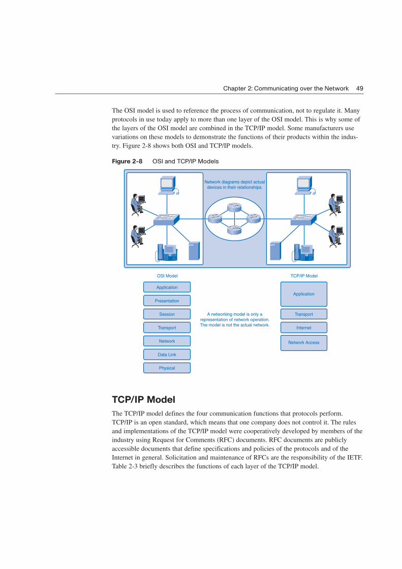
The OSI model is used to reference the process of communication, not to regulate it. Many
protocols in use today apply to more than one layer of the OSI model. This is why some of
the layers of the OSI model are combined in the TCP/IP model. Some manufacturers use
variations on these models to demonstrate the functions of their products within the indus-
try. Figure 2-8 shows both OSI and TCP/IP models.
Figure 2-8 OSI and TCP/IP Models
TCP/IP Model
The TCP/IP model defines the four communication functions that protocols perform.
TCP/IP is an open standard, which means that one company does not control it. The rules
and implementations of the TCP/IP model were cooperatively developed by members of the
industry using Request for Comments (RFC) documents. RFC documents are publicly
accessible documents that define specifications and policies of the protocols and of the
Internet in general. Solicitation and maintenance of RFCs are the responsibility of the IETF.
Table 2-3 briefly describes the functions of each layer of the TCP/IP model.
Chapter 2: Communicating over the Network 49
Network diagrams depict actual
devices in their relationships.
A networking model is only a
representation of network operation.
The model is not the actual network.
OSI Model
Application
Presentation
Session
Transport
Network
Data Link
Physical
TCP/IP Model
Application
Transport
Internet
Network Access
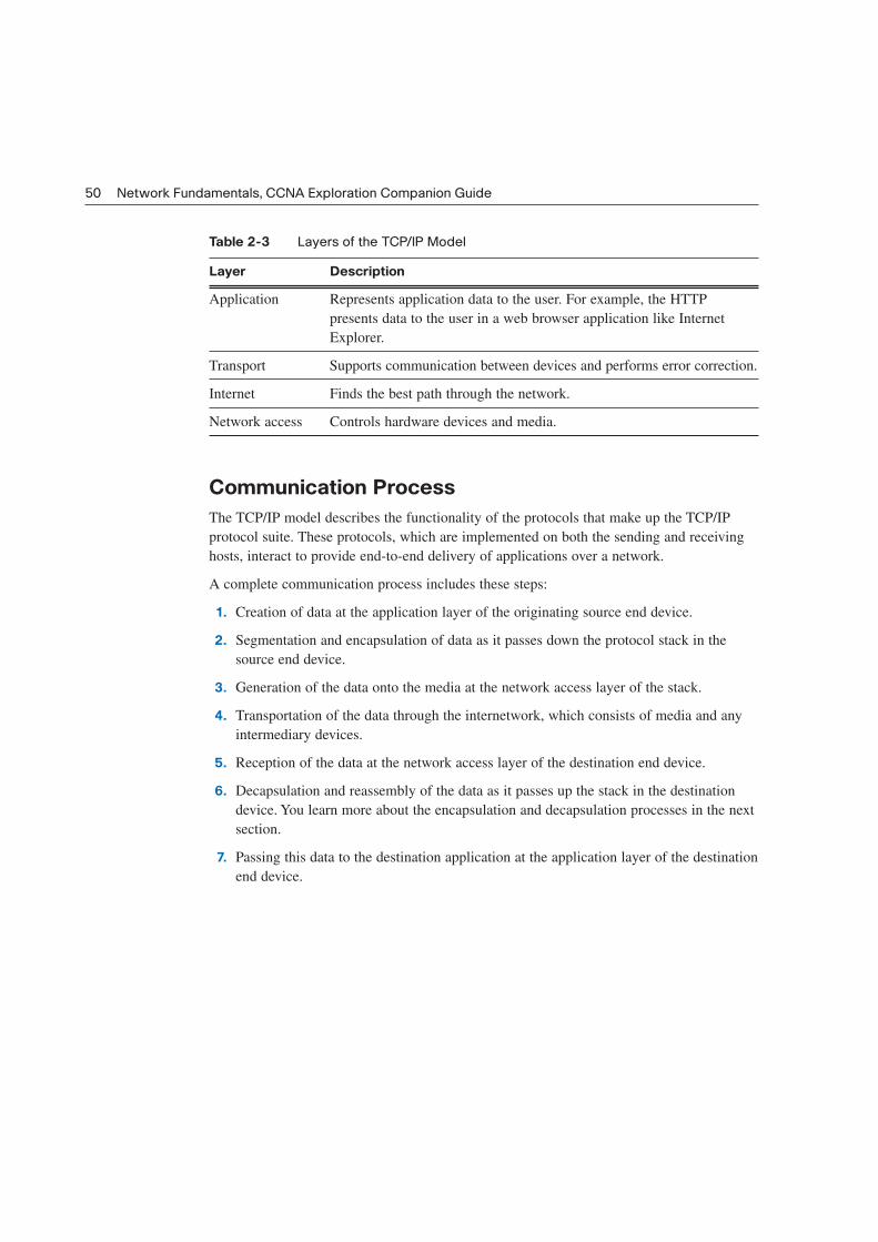
Table 2-3 Layers of the TCP/IP Model
Layer Description
Application Represents application data to the user. For example, the HTTP
presents data to the user in a web browser application like Internet
Explorer.
Transport Supports communication between devices and performs error correction.
Internet Finds the best path through the network.
Network access Controls hardware devices and media.
Communication Process
The TCP/IP model describes the functionality of the protocols that make up the TCP/IP
protocol suite. These protocols, which are implemented on both the sending and receiving
hosts, interact to provide end-to-end delivery of applications over a network.
A complete communication process includes these steps:
1. Creation of data at the application layer of the originating source end device.
2. Segmentation and encapsulation of data as it passes down the protocol stack in the
source end device.
3. Generation of the data onto the media at the network access layer of the stack.
4. Transportation of the data through the internetwork, which consists of media and any
intermediary devices.
5. Reception of the data at the network access layer of the destination end device.
6. Decapsulation and reassembly of the data as it passes up the stack in the destination
device. You learn more about the encapsulation and decapsulation processes in the next
section.
7. Passing this data to the destination application at the application layer of the destination
end device.
50 Network Fundamentals, CCNA Exploration Companion Guide

Protocol Data Units and Encapsulation
For application data to travel uncorrupted from one host to another, header (or control data),
which contains control and addressing information, is added to the data as it moves down
the layers. The process of adding control information as it passes through the layered model
is called encapsulation. Decapsulation is the process of removing the extra information
and sending only the original application data up to the destination application layer.
Each layer adds control information at each step. The generic term for data at each level is
protocol data unit (PDU), but a PDU is different at each layer. For example, a PDU at the
internetwork layer is different from the PDU at the transport layer, because internetwork
layer data has been added to the transport layer data. The different names for PDUs at each
layer are listed in Table 2-4.
Table 2-4 Protocol Data Unit Naming Conventions
PDU Name Layer
Data Application layer PDU
Segment Transport layer PDU
Packet Internetwork layer PDU
Frame Network access layer PDU
Bits PDU used for the physical transmission of binary data over media
Figure 2-9 depicts the encapsulation process and shows how PDUs are modified.
Figure 2-9 Encapsulation
Chapter 2: Communicating over the Network 51
Passing
Down the
Stack
1100010101000101100101001010101001
Frame
Header
Network
HeaderDataTransport
Header
Frame
Header
Network
HeaderDataTransport
Header
DataTransport
Header
DataDataData
DataData
Segment
Packet
Frame (Medium
Dependent)
Bits

Sending and Receiving Process
The common task of sending an e-mail has many steps in the process. Using the proper
terms for PDUs and the TCP/IP model, the process of sending the e-mail is as follows:
1. An end user, using an e-mail application, creates data. The application layer codes the
data as e-mail and sends the data to the transport layer.
2. The message is segmented, or broken into pieces, for transport. The transport layer
adds control information in a header so that it can be assigned to the correct process
and all segments put into proper order at the destination. The segment is sent down to
the internetwork layer.
3. The internetwork layer adds IP addressing information in an IP header. The segment is
now an addressed packet that can be handled by routers en route to the destination. The
internetwork layer sends the packet down to the network access layer.
4. The network access layer creates an Ethernet frame with local network physical
address information in the header. This enables the packet to get to the local router and
out to the web. The frame also contains a trailer with error-checking information. After
the frame is created, it is encoded into bits and sent onto the media to the destination.
5. At the destination host, the process is reversed. The frame is decapsulated to a packet,
then to a segment, and then the transport layer puts all segments into the proper order.
6. When all data has arrived and is ready, it is sent to the application layer, and then the
original application data goes to the receiver’s e-mail application. The message is
successful.
Figure 2-10 depicts these steps as an encapsulated message travels down the TCP/IP model
on the source and is en route to the destination for decapsulation.
Figure 2-10 Steps in the Communication Process
52 Network Fundamentals, CCNA Exploration Companion Guide
Application
Transport
Internet
Application
TCP/IP Model TCP/IP Model
Transport
Internet
1
2
3
6
5
Network Access Network Access4

OSI Model
The Open Systems Interconnection (OSI) model, known as the OSI model, provides an
abstract description of the network communication process. Developed by the International
Organization for Standardization (ISO) to provide a road map for nonproprietary protocol
development, the OSI model did not evolve as readily as the TCP/IP model. Many of the
OSI protocols are no longer in use, but knowledge of the model as a reference is a basic
expectation for networking professionals. Many professionals refer to the layers by number
rather than name, so it is important to know both.
The OSI model is just a reference model, so manufacturers have been free to create protocols
and products that combine functions of one or more layers. New protocols might not exactly
match the functions described at each layer but might fit into parts of two different layers.
As designed, the communication process begins at the application layer of the source, and data
is passed down to each lower layer to be encapsulated with supporting data until it reaches the
physical layer and is put out on the media. When the data arrives at the destination, it is passed
back up through layers and decapsulated by each layer. Each layer provides data services to the
layer directly above by preparing information coming down the model or going up.
Table 2-5 briefly describes each layer of the OSI model. Each layer will be explored in its
own chapter later in this book.
Table 2-5 OSI Model
No. Layer Name Description
7 Application Performs services for the applications used by the end users.
6 Presentation Provides data format information to the application. For example,
the presentation layer tells the application layer whether there is
encryption or whether it is a .jpg picture.
5 Session Manages sessions between users. For example, the session layer
will synchronize multiple web sessions and voice and video data
in web conferences.
4 Transport Defines data segments and numbers them at the source, transfers
the data, and reassembles the data at the destination.
3 Network Creates and addresses packets for end-to-end delivery through
intermediary devices in other networks.
2 Data Link Creates and addresses frames for host-to-host delivery on the
local LANs and between WAN devices.
1 Physical Transmits binary data over media between devices. Physical layer
protocols define media specifications.
Chapter 2: Communicating over the Network 53

Comparing the OSI Model to the TCP/IP Model
The TCP/IP model evolved faster than the OSI model and is now more practical in describ-
ing network communication functions. The OSI model describes in detail functions that
occur at the upper layers on the hosts, while networking is largely a function of the lower
layers. Figure 2-11 shows the two models side by side for comparison.
Figure 2-11 Comparing the OSI and TCP/IP Models
When juxtaposed, you can see that the functions of the application, presentation, and ses-
sion layers of the OSI model are combined into one application layer in the TCP/IP model.
The bulk of networking functions reside at the transport and the network layers, so they
remain individual layers. TCP operates at the transport layer, and IP operates at the Internet
layer.
The data link and physical layers of the OSI model combine to make the network access
layer of the TCP/IP model.
Use of the TCP/IP Protocols and the OSI Model in Packet Tracer (2.4.8.2)
In this activity, you will see how Packet Tracer uses the OSI model as a reference to display
the encapsulation details of a variety of the TCP/IP protocols. Use file e1-2482.pka on the
CD-ROM that accompanies this book to perform this activity using Packet Tracer.
54 Network Fundamentals, CCNA Exploration Companion Guide
OSI Model
Application
Presentation
Session
Transport
Network
Data Link
Physical
TCP/IP Model
Application
Transport
Internet
Network Access
1
2
3
4
5
6
7
Packet Tracer
Activity
Network Addressing
Successful communication requires that a sender and a receiver know how to get messages
to each other. Postal systems use geography to deliver mail to physical addresses, but get-
ting messages between computers is a more complicated matter. With the Internet, comput-
ers can communicate regardless of physical location.
Instead of using a geographical addressing scheme for computers, engineers devised a logi-
cal addressing scheme using numeric network addresses. The following sections introduce
the addressing process. Chapter 6, “Addressing the Network: IPv4,” explores network
addressing in greater detail.
Addressing in the Network
There are millions of computers in use on the web and billions of messages traversing net-
works at any given time, so proper addressing is essential to make sure that the sent mes-
sage arrives intact at the proper destination. Addressing of data happens in three different
layers of the OSI model. The PDU at each layer adds address information for use by the
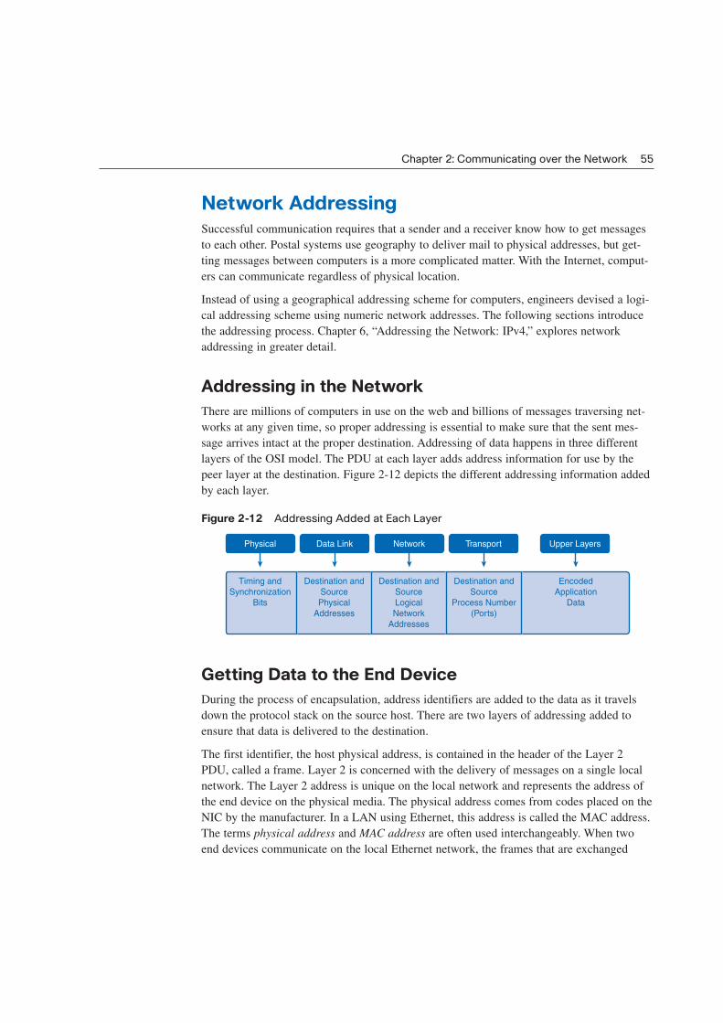
peer layer at the destination. Figure 2-12 depicts the different addressing information added
by each layer.
Figure 2-12 Addressing Added at Each Layer
Getting Data to the End Device
During the process of encapsulation, address identifiers are added to the data as it travels
down the protocol stack on the source host. There are two layers of addressing added to
ensure that data is delivered to the destination.
The first identifier, the host physical address, is contained in the header of the Layer 2
PDU, called a frame. Layer 2 is concerned with the delivery of messages on a single local
network. The Layer 2 address is unique on the local network and represents the address of
the end device on the physical media. The physical address comes from codes placed on the
NIC by the manufacturer. In a LAN using Ethernet, this address is called the MAC address.
The terms physical address and MAC address are often used interchangeably. When two
end devices communicate on the local Ethernet network, the frames that are exchanged
Chapter 2: Communicating over the Network 55
Physical
Timing and
Synchronization
Bits
Destination and
Source
Physical
Addresses
Destination and
Source
Logical
Network
Addresses
Destination and
Source
Process Number
(Ports)
Encoded
Application
Data
Data Link Network Transport Upper Layers
between them contain the destination and source MAC addresses. After a frame is success-
fully received by the destination host, the Layer 2 address information is removed as the
data is decapsulated and moved up the protocol stack to Layer 3.
Getting Data Through the Internetwork
Layer 3 protocols are primarily designed to move data from one local network to another
local network within an internetwork. Whereas Layer 2 addresses are only used to commu-
nicate between devices on a single local network, Layer 3 addresses must include identifiers
that enable intermediary network devices to locate hosts on different networks. In the
TCP/IP protocol suite, every IP host address contains information about the network where
the host is located.
At the boundary of each local network, an intermediary network device, usually a router,
decapsulates the frame to read the destination host address contained in the header of the
packet, the Layer 3 PDU. Routers use the network identifier portion of this address to deter-
mine which path to use to reach the destination host. When the path is determined, the
router encapsulates the packet in a new frame and sends it on its way toward the destination
end device. When the frame reaches its final destination, the frame and packet headers are
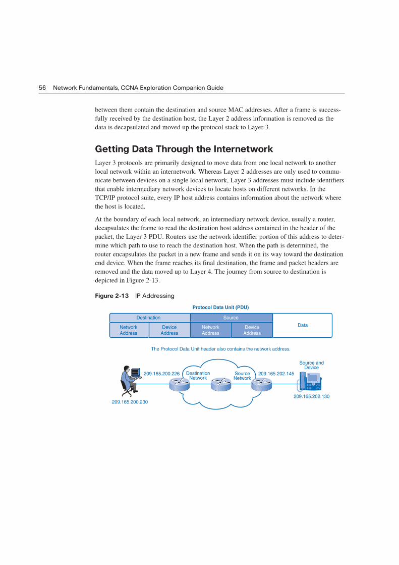
removed and the data moved up to Layer 4. The journey from source to destination is
depicted in Figure 2-13.
Figure 2-13 IP Addressing
56 Network Fundamentals, CCNA Exploration Companion Guide
SourceNetwork
DestinationNetwork
209.165.200.226
209.165.200.230209.165.202.130
Source andDevice
209.165.202.145
Network
Address
Device
Address
Destination Source
Network
Address
Device
Address
Data
Protocol Data Unit (PDU)
The Protocol Data Unit header also contains the network address.

Getting Data to the Right Application
At Layer 4, information contained in the PDU header does not identify a destination host or
a destination network. What it does identify is the specific process or service running on the
destination host device that will act on the data being delivered. Hosts, whether they are
clients or servers on the Internet, can run multiple network applications simultaneously.
People using PCs often have an e-mail client running at the same time as a web browser, an
instant messaging program, some streaming media, and perhaps even a game. All these sep-
arately running programs are examples of individual processes.
Viewing a web page invokes at least one network process. Clicking a hyperlink causes a
web browser to communicate with a web server. At the same time, in the background, an
e-mail client can be sending and receiving e-mail, and a colleague or friend can be sending
an instant message.
Think about a computer that has only one network interface on it. All the data streams cre-
ated by the applications that are running on the PC enter and leave through that one inter-
face, yet instant messages do not pop up in the middle of a word processor document or
e-mail showing up in a game.
This is because the transport layer adds port numbers to its segment header information to
ensure that the destination host knows which application process is to receive the packet.
The end host assigns a port number to each type of traffic going in and out. A user can send
and receive many types of traffic over a single network interface, and using port numbers
for each segment keeps traffic for web pages separate from e-mail traffic and so on. The
segment contains both source and destination ports in case the receiver needs to contact the
sender. Figure 2-14 shows different data types for two different services on an end device.
Figure 2-14 Port Addressing
Chapter 2: Communicating over the Network 57
Port NumberFile Transfer DataService:
File Transfer
Service:
Terminal Session
Service:
Electronic Mail
Port NumberTerminal
Session Data
58 Network Fundamentals, CCNA Exploration Companion Guide
Summary
Communication in data networks requires a source device and a destination device with a
medium connecting the two. For messages to travel to other networks, intermediary devices
such as routers are necessary.
The devices that handle messages and the media that carry them comply with communica-
tion rules called protocols. Many protocols can work together in a stack to complete the
process of network communication.
Layered models describe the various steps that must occur for successful communication.
The OSI and TCP/IP models are the most common models used in networking and can
serve as a guide to the different protocols and devices used at each layer. Models are useful
for students and companies in analyzing and troubleshooting networks as well as for future
development of protocols.
Application data is sent down the protocol stacks and is encapsulated at each layer with
addressing and control information. The data is segmented into pieces, addressed, and then
encoded on the media. The process is reversed at the destination.
Activities and Labs
The activities and labs available in the companion Network Fundamentals, CCNA
Exploration Labs and Study Guide (ISBN 1-58713-203-6) provide hands-on practice with
the following topics introduced in this chapter:
Activity 2-1: Using NeoTrace to View Internetworks (2.2.5.1)
In this activity, you will observe the flow of information across the Internet. This activity
should be performed on a computer that has Internet access and access to a command line.
You will use the Windows embedded tracert utility and then the more enhanced NeoTrace
program. This lab also assumes you have the installation of NeoTrace.
Lab 2-1: Topology Orientation and Building a Small Network (2.6.1.1)
This lab begins by having you construct two small networks. It then shows how they are
connected to the larger hands-on lab network used throughout the course. This network is a
simplified model of a section of the Internet and will be used to develop your practical net-
working skills.

Chapter 2: Communicating over the Network 59
Lab 2-2: Using Wireshark to View Protocol Data Units (2.6.2.1)
In this lab, you will begin learning about the Wireshark tool by capturing (“sniffing”) traffic
off the model network.
Many of the hands-on labs include Packet Tracer companion activities where you can use
Packet Tracer to complete a simulation of the lab. Look for this icon in the Network
Fundamentals, CCNA Exploration Labs and Study Guide (ISBN 1-58713-203-6) for hands-
on labs that have Packet Tracer companion activities.
Check Your Understanding
Complete all the review questions listed here to test your understanding of the topics and
concepts in this chapter. The appendix, “Check Your Understanding and Challenge
Questions Answer Key,” lists the answers.
1. Which OSI layer is associated with IP addressing?
A. 1
B. 2
C. 3
D. 4
2. The elements of communication include a message source, a message destination, and
a ___________________, or medium, to transport the message.
3. Which type of addressing is found at the OSI Layer 2? (Choose two.)
A. Logical
B. Physical
C. MAC
D. IP
E. Port
4. When a server responds to a web request, what occurs next in the encapsulation
process after the web page data is formatted and separated into TCP segments?
A. The client decapsulates the segment and opens the web page.
B. The client adds the appropriate physical address to the segments so that the server
can forward the data.
C. The server converts the data to bits for transport across the medium.
D. The server adds the source and destination IP address to each segment header to
deliver the packets to the destination.
E. The server adds the source and destination physical addresses to the packet header.
Packet Tracer
Companion

60 Network Fundamentals, CCNA Exploration Companion Guide
5. Which term describes a specific set of rules that determine the formatting of messages
and the process of encapsulation used to forward data?
A. Segmentation
B. Protocol
C. Multiplexing
D. QoS
E. Reassembly
6. A limited-use protocol owned by a company is considered to be
_________________________.
7. Which one of the following is associated with Layer 4 of the OSI model?
A. IP
B. TCP
C. FTP
D. TFTP
8. The device that connects a device to the media is called a/an
_________________________.
9. Which of the following terms defines dividing data streams into smaller pieces suitable
for transmission?
A. Protocol
B. Multiplexing
C. Segmentation
D. Encapsulation
10. A device that moves data between networks is a _______________.
11. Which of the following is the process for interweaving multiple data streams onto one
shared communication channel or network medium?
A. Multicasting
B. Multiplexing
C. Encapsulation
D. Multidirecting

Chapter 2: Communicating over the Network 61
12. Which of the following is associated with the network layer?
A. IP address
B. Frames
C. MAC address
D. Physical addressing
13. Which of the following is the correct “top down” order of the OSI model?
A. Application, presentation, session, network, transport, data link, physical
B. Application, presentation, session, transport, network, data link, physical
C. Application, session, presentation, transport, network, data link, physical
D. Application, presentation, session, network, data link, transport, physical
14. Which layer of the OSI model is concerned with end-to-end message delivery over the
network?
A. Network
B. Transport
C. Data link
D. Application
Challenge Questions and Activities
These questions require a deeper application of the concepts covered in this chapter. You
can find the answers in the appendix.
1. Which layers of the OSI model are combined into other layers of the TCP/IP model?
(Choose all that apply.)
A. Network
B. Presentation
C. Internet
D. Data link
E. Application
F. Physical
G. Session
H. Network access
I. Transport

62 Network Fundamentals, CCNA Exploration Companion Guide
2. Which of the following are true about LANs and WANs? (Choose two.)
A. LANs connect groups of networks using ISPs.
B. LANs consist of hosts communicating with logical addresses.
C. WANs connect groups of networks using TSPs.
D. WANs connect LANs.
E. Hosts on a LAN use physical addressing to communicate.
Look for this icon in Network Fundamentals, CCNA Exploration Labs and Study Guide
(ISBN 1-58713-203-6) for instructions on how to perform the Packet Tracer Skills
Integration Challenge for this chapter.
To Learn More
The following questions encourage you to reflect on the topics discussed in this chapter.
Your instructor might ask you to research the questions and discuss your findings in class.
1. How are the classifications LAN, WAN, and Internet still useful, and how might they
be problematic in classifying networks?
2. What are strengths and weaknesses of the OSI and TCP/IP models? Why are both mod-
els still used?
3. Metaphors and analogies can be powerful aids to learning but must be used with care.
Consider issues of devices, protocols, and addressing in the following systems:
Standard postal service
Express parcel delivery service
Traditional (analog) telephone system
Internet telephony
Containerized shipping services
Terrestrial and satellite radio systems
Broadcast and cable television
4. Discuss what you see as common factors among these systems. Apply any similarities
to other networks.
5. How could you apply these common concepts to developing new communications sys-
tems and networks?
Packet Tracer
Challenge


![Cap[1].2 - Communicating Over the Network](https://img.pdfslide.net/doc/110x75/577d2a131a28ab4e1ea897d8/cap12-communicating-over-the-network.jpg)