Embed Size (px)
Citation preview
Communication Command Instruction Manual
RM3544-01 RM3545 RM3545-01 RM3545-02
RESISTANCE METER
This manual explains the communication commands for Models RM3544 / RM3545 Resistance Meter.
Please refer to the instruction manual for Models RM3544 / RM3545 for details regarding command settings.
Although all reasonable care has been taken in the production of this manual, should you find any points which are unclear or in error, please contact your local distributor or the HIOKI International Sales & Marketing Division at [email protected].
In the interest of product development, the contents of this manual may be subject to revision without notice.
Microsoft, MS, MS-DOS, and Windows, are registered trademarks or trademarks of Microsoft Corporation in the U.S.A. and other countries.
All other names are registered trademarks or trademarks of their respective companies.
July 2016 RM3544A986-03

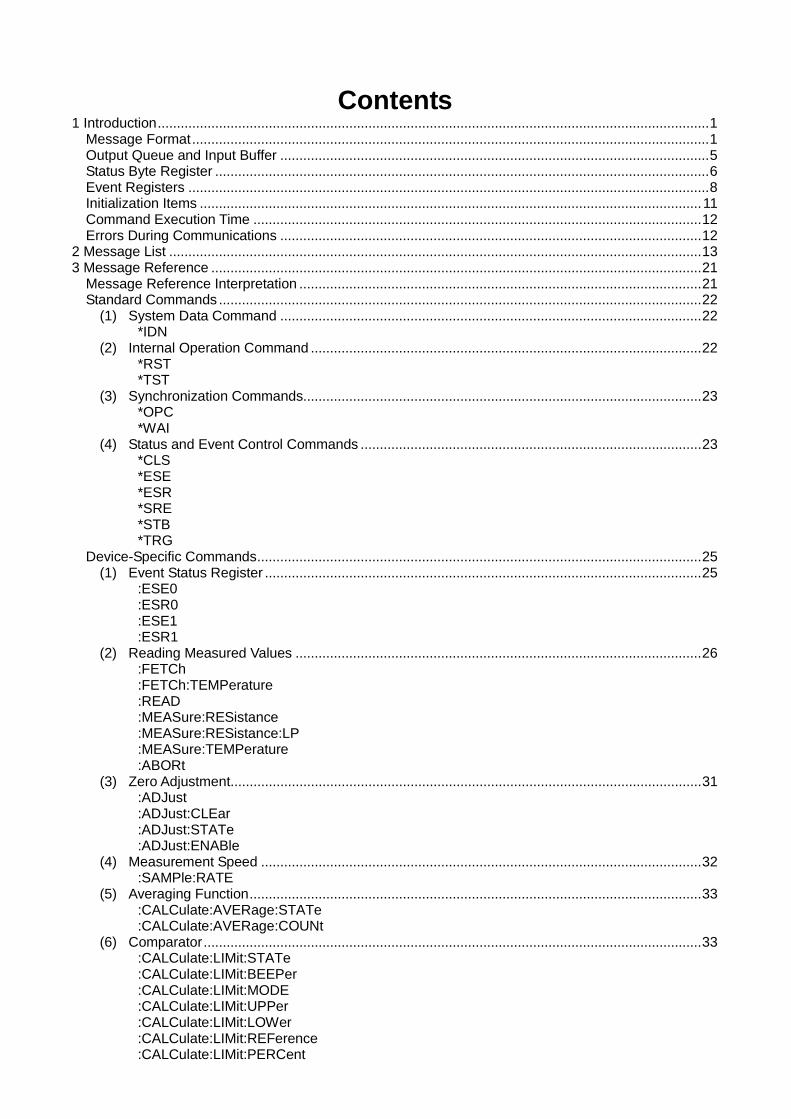
Contents 1 Introduction ................................................................................................................................................ 1
Message Format ....................................................................................................................................... 1 Output Queue and Input Buffer ................................................................................................................ 5 Status Byte Register ................................................................................................................................. 6 Event Registers ........................................................................................................................................ 8 Initialization Items ................................................................................................................................... 11 Command Execution Time ..................................................................................................................... 12 Errors During Communications .............................................................................................................. 12
2 Message List ........................................................................................................................................... 13 3 Message Reference ................................................................................................................................ 21
Message Reference Interpretation ......................................................................................................... 21 Standard Commands .............................................................................................................................. 22
(1) System Data Command .............................................................................................................. 22 *IDN
(2) Internal Operation Command ...................................................................................................... 22 *RST *TST
(3) Synchronization Commands........................................................................................................ 23 *OPC *WAI
(4) Status and Event Control Commands ......................................................................................... 23 *CLS *ESE *ESR *SRE *STB *TRG
Device-Specific Commands .................................................................................................................... 25 (1) Event Status Register .................................................................................................................. 25
:ESE0 :ESR0 :ESE1 :ESR1
(2) Reading Measured Values .......................................................................................................... 26 :FETCh :FETCh:TEMPerature :READ :MEASure:RESistance :MEASure:RESistance:LP :MEASure:TEMPerature :ABORt
(3) Zero Adjustment ........................................................................................................................... 31 :ADJust :ADJust:CLEar :ADJust:STATe :ADJust:ENABle
(4) Measurement Speed ................................................................................................................... 32 :SAMPle:RATE
(5) Averaging Function ...................................................................................................................... 33 :CALCulate:AVERage:STATe :CALCulate:AVERage:COUNt
(6) Comparator .................................................................................................................................. 33 :CALCulate:LIMit:STATe :CALCulate:LIMit:BEEPer :CALCulate:LIMit:MODE :CALCulate:LIMit:UPPer :CALCulate:LIMit:LOWer :CALCulate:LIMit:REFerence :CALCulate:LIMit:PERCent
:CALCulate:LIMit:RESult :CALCulate:LIMit:JUDGe:CONDition :CALCulate:LIMit:JUDGe :CALCulate:LIMit:JUDGe:TOTal
(7) BIN Function RM3545 ................................................................................................................. 36 :CALCulate:BIN:STATe :CALCulate:BIN:ENABle :CALCulate:BIN:MODE :CALCulate:BIN:UPPer :CALCulate:BIN:LOWer :CALCulate:BIN:REFerence :CALCulate:BIN:PERCent :CALCulate:BIN:RESult
(8) Statistical Functions RM3545 ...................................................................................................... 38 :CALCulate:STATistics:STATe :CALCulate:STATistics:CLEar :CALCulate:STATistics:NUMBer? :CALCulate:STATistics:MEAN? :CALCulate:STATistics:MAXimum? :CALCulate:STATistics:MINimum? :CALCulate:STATistics:LIMit? :CALCulate:STATistics:BIN? :CALCulate:STATistics:DEViation? :CALCulate:STATistics:CP?
(9) Scaling ......................................................................................................................................... 39 :CALCulate:SCALing:STATe :CALCulate:SCALing:PARameterA :CALCulate:SCALing:PARameterB :CALCulate:SCALing:UNIT
(10) Temperature Conversion (∆t) RM3545 ....................................................................................... 40 :CALCulate:TCONversion:DELTa:STATe :CALCulate:TCONversion:DELTa:PARameter
(11) Temperature Correction (TC) ...................................................................................................... 41 :CALCulate:TCORrect:STATe :CALCulate:TCORrect:PARameter
(12) LCD Settings ................................................................................................................................ 42 :DISPlay:CONTrast :DISPlay:BACKlight
(13) Memory Functions RM3545 ........................................................................................................ 42 :MEMory:STATe :MEMory:CLEar :MEMory:COUNt :MEMory:DATA
(14) Hold .............................................................................................................................................. 43 [:SENSe:]HOLD:AUTO [:SENSe:]HOLD:STATe [:SENSe:]HOLD:OFF
(15) Multiplexer Settings RM3545 ..................................................................................................... 44 [:SENSe:]WIRE [:SENSe:]SCAN:MODE [:SENSe:]SCAN:STATe [:SENSe:]SCAN:RESet [:SENSe:]SCAN:FAIL:STOP [:SENSe:]SCAN:DATA [:SENSe:]CH [:SENSe:]CH [:SENSe:]CH:STATe [:SENSe:]CH:AVAirable [:SENSe:]INSTrument [:SENSe:]TERMinal
(16) Multiplexer Channel Reset RM3545 .......................................................................................... 47
[:SENSe:]CHReset (17) Low-Power Resistance Measurement RM3545 ......................................................................... 48
[:SENSe:]RESistance:LP:STATe (18) Measurement Range ................................................................................................................... 48
[:SENSe:]RESistance:RANGe [:SENSe:]RESistance:RANGe:AUTO [:SENSe:]RESistance:LP:RANGe
(19) 100MΩ Range High Precision Function RM3545 ..................................................................... 49 [:SENSe:]RESistance:PRECision
(20) Switching Measurement Current RM3545 .................................................................................. 49 [:SENSe:]RESistance:CURRent
(21) Offset Voltage Correction Function (OVC) RM3545 ................................................................... 50 [:SENSe:]RESistance:OVC
(22) Contact Improver RM3545 .......................................................................................................... 50 [:SENSe:]RESistance:CIMProve¥l 4 ¥ n .................................................................................. 50
(23) Current Error Mode ...................................................................................................................... 50 [:SENSe:]RESistance:ERRor:CURRentcheck
(24) Contact Check RM3545 .............................................................................................................. 51 [:SENSe:]RESistance:CONTactcheck [:SENSe:]RESistance:LP:CONTactcheck
(25) Setting Number of Digits .............................................................................................................. 52 [:SENSe:]RESistance:DIGits
(26) Temperature Measurement (Analog Input) RM3545 .................................................................. 52 [:SENSe:]TEMPerature:SENSor [:SENSe:]TEMPerature:PARameter
(27) Triggering ..................................................................................................................................... 53 :INITiate:CONTinuous :INITiate[:IMMediate] :TRIGger:SOURce :TRIGger:EDGE
(28) Delay RM3545 ............................................................................................................................. 57 :TRIGger:DELay :TRIGger:DELay:AUTO
(29) Self-Calibration RM3545 ............................................................................................................. 57 :SYSTem:CALibration :SYSTem:CALibration:AUTO
(30) Saving and Reading Measurement Conditions ........................................................................... 58 :SYSTem:PANel:SAVE/:LOAD :SYSTem:PANel:NAME :SYSTem:PANel:CLEar
(31) Key-Lock ...................................................................................................................................... 59 :SYSTem:KLOCk
(32) Line Frequency ............................................................................................................................ 59 :SYSTem:LFRequency
(33) Clock RM3545 ............................................................................................................................. 60 :SYSTem:DATE :SYSTem:TIME
(34) Key Beeper .................................................................................................................................. 60 :SYSTem:BEEPer:STATe
(35) Communications Settings ............................................................................................................ 61 :SYSTem:LOCal :SYSTem:DATAout :SYSTem:HEADer :SYSTem:TERMinator
(36) System Reset .............................................................................................................................. 62 :SYSTem:RESet
(37) EXT I/O ........................................................................................................................................ 62 :IO:MODE? :IO:INPut? :IO:OUTPut :IO:FILTer:STATe
:IO:FILTer:TIME :IO:JUDGe:MODE :IO:EOM:MODE :IO:EOM:PULSe
(38) Multiplexer Unit RM3545 ............................................................................................................ 64 :UNIT:IDN :UNIT:SCOunt :UNIT:TEST
4 Multiplexer Commands ............................................................................................................................ 65 Multiplexer Settings ................................................................................................................................ 65
Multiplexer Measurement .................................................................................................................... 66 5 Data Exporting Methods .......................................................................................................................... 69 6 Sample Programs .................................................................................................................................... 72
Using Visual Basic 5.0 or 6.0 .................................................................................................................. 72 RS-232C/USB Communications (Using Microsoft Visual Basic Professional MSComm) .................. 72 GP-IB Communications (Using National Instruments GP-IB Board) .................................................. 77
Using Visual Basic2010 .......................................................................................................................... 82 7 Device Compliance Statement [GP-IB] ................................................................................................... 89
1
1 Introduction
In this publication, items relevant only to the RM3544-01 are indicated as RM3544, and items relevant only to the RM3545, RM3545-01, and RM3545-02 are indicated as RM3545. Also, the RM354-01, RM3545, RM3545-01, and RM3545-02 are indicated as “the instrument.”
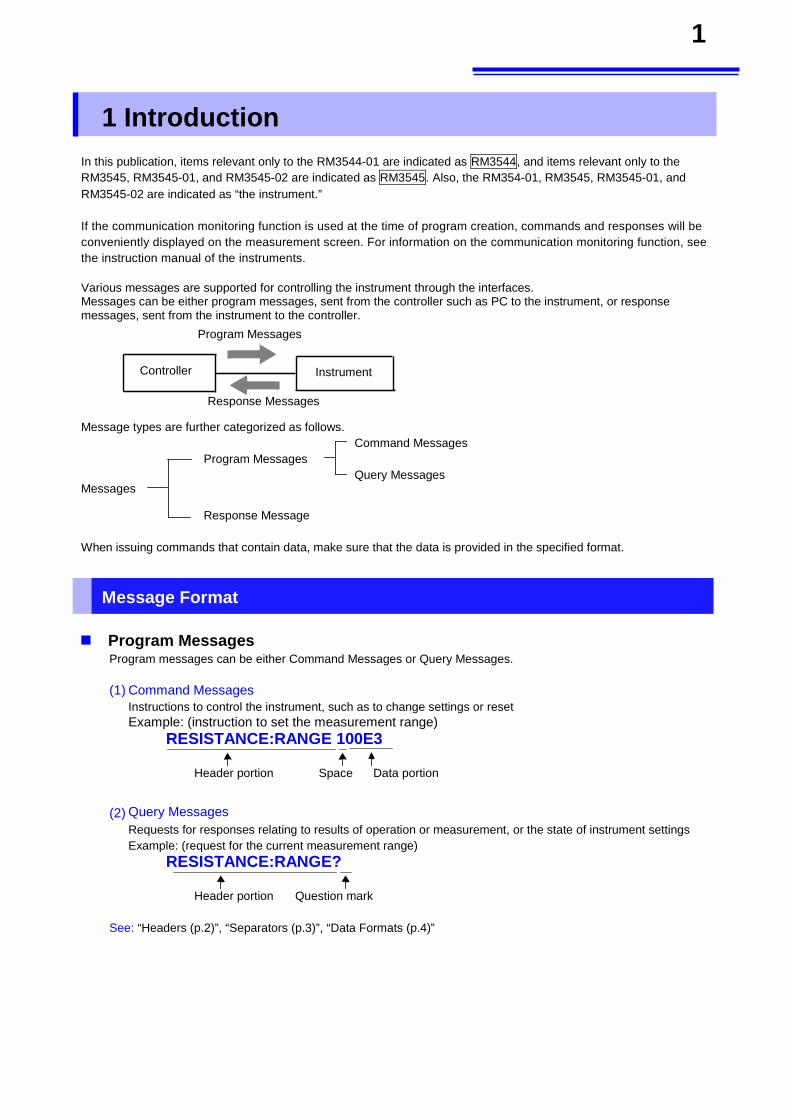
If the communication monitoring function is used at the time of program creation, commands and responses will be conveniently displayed on the measurement screen. For information on the communication monitoring function, see the instruction manual of the instruments. Various messages are supported for controlling the instrument through the interfaces. Messages can be either program messages, sent from the controller such as PC to the instrument, or response messages, sent from the instrument to the controller.
Message types are further categorized as follows. Command Messages
Program Messages
Query Messages Messages
Response Message
When issuing commands that contain data, make sure that the data is provided in the specified format.
Message Format Program Messages
Program messages can be either Command Messages or Query Messages.
(1) Command Messages Instructions to control the instrument, such as to change settings or reset Example: (instruction to set the measurement range)
RESISTANCE:RANGE 100E3
Header portion Space Data portion
(2) Query Messages
Requests for responses relating to results of operation or measurement, or the state of instrument settings Example: (request for the current measurement range)
RESISTANCE:RANGE?
Header portion Question mark
See: “Headers (p.2)”, “Separators (p.3)”, “Data Formats (p.4)”
Program Messages
Response Messages
Controller Instrument
2
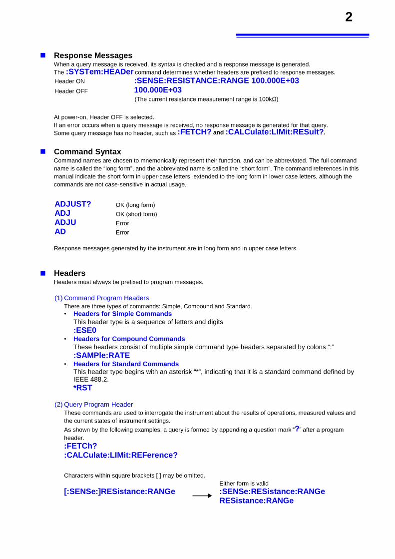
Response Messages When a query message is received, its syntax is checked and a response message is generated. The :SYSTem:HEADer command determines whether headers are prefixed to response messages.
Header ON :SENSE:RESISTANCE:RANGE 100.000E+03
Header OFF 100.000E+03 (The current resistance measurement range is 100kΩ)
At power-on, Header OFF is selected. If an error occurs when a query message is received, no response message is generated for that query. Some query message has no header, such as :FETCH? and :CALCulate:LIMit:RESult?.
Command Syntax
Command names are chosen to mnemonically represent their function, and can be abbreviated. The full command name is called the “long form”, and the abbreviated name is called the “short form”. The command references in this manual indicate the short form in upper-case letters, extended to the long form in lower case letters, although the commands are not case-sensitive in actual usage.
ADJUST? OK (long form)
ADJ OK (short form)
ADJU Error
AD Error
Response messages generated by the instrument are in long form and in upper case letters.
Headers Headers must always be prefixed to program messages.
(1) Command Program Headers There are three types of commands: Simple, Compound and Standard. • Headers for Simple Commands
This header type is a sequence of letters and digits
:ESE0 • Headers for Compound Commands
These headers consist of multiple simple command type headers separated by colons “:” :SAMPle:RATE
• Headers for Standard Commands This header type begins with an asterisk “*”, indicating that it is a standard command defined by IEEE 488.2. *RST
(2) Query Program Header These commands are used to interrogate the instrument about the results of operations, measured values and the current states of instrument settings.
As shown by the following examples, a query is formed by appending a question mark “?” after a program header. :FETCh? :CALCulate:LIMit:REFerence?
Characters within square brackets [ ] may be omitted.
Either form is valid [:SENSe:]RESistance:RANGe :SENSe:RESistance:RANGe
RESistance:RANGe
3
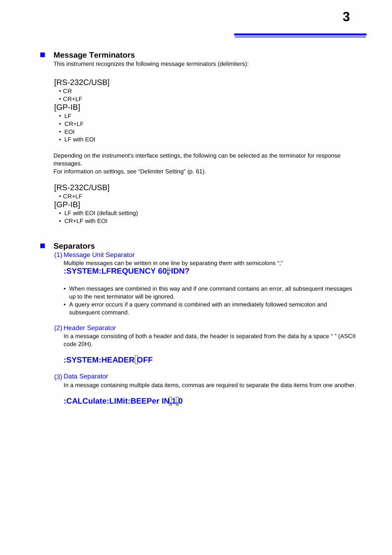
Message Terminators This instrument recognizes the following message terminators (delimiters):
[RS-232C/USB]
• CR
• CR+LF
[GP-IB] • LF
• CR+LF
• EOI • LF with EOI
Depending on the instrument's interface settings, the following can be selected as the terminator for response messages. For information on settings, see “Delimiter Setting” (p. 61).
[RS-232C/USB] • CR+LF
[GP-IB] • LF with EOI (default setting) • CR+LF with EOI
Separators (1) Message Unit Separator
Multiple messages can be written in one line by separating them with semicolons “;” :SYSTEM:LFREQUENCY 60;*IDN?
• When messages are combined in this way and if one command contains an error, all subsequent messages up to the next terminator will be ignored.
• A query error occurs if a query command is combined with an immediately followed semicolon and subsequent command.
(2) Header Separator
In a message consisting of both a header and data, the header is separated from the data by a space “ ” (ASCII code 20H).
:SYSTEM:HEADER OFF
(3) Data Separator In a message containing multiple data items, commas are required to separate the data items from one another. :CALCulate:LIMit:BEEPer IN,1,0
4
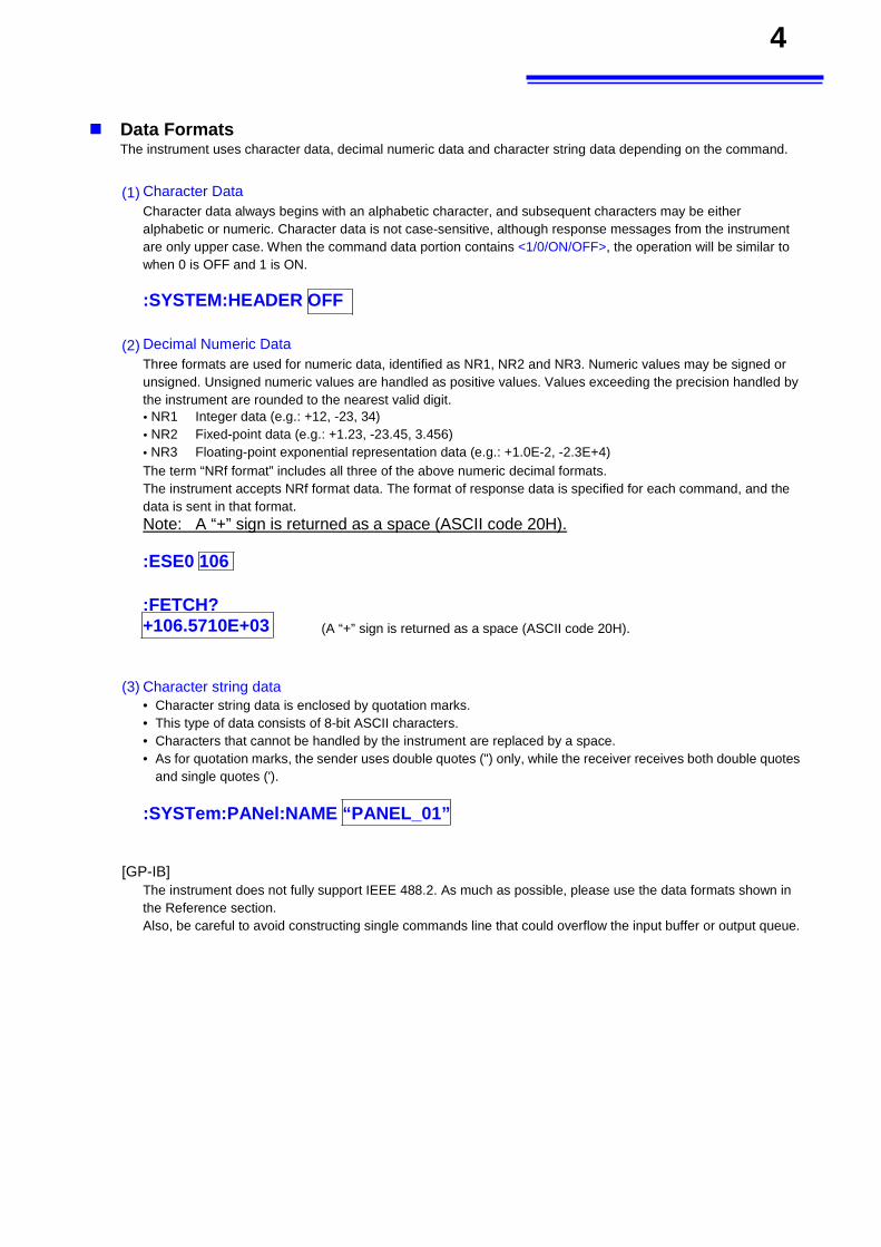
Data Formats
The instrument uses character data, decimal numeric data and character string data depending on the command.
(1) Character Data Character data always begins with an alphabetic character, and subsequent characters may be either alphabetic or numeric. Character data is not case-sensitive, although response messages from the instrument are only upper case. When the command data portion contains <1/0/ON/OFF>, the operation will be similar to when 0 is OFF and 1 is ON.
:SYSTEM:HEADER OFF
(2) Decimal Numeric Data
Three formats are used for numeric data, identified as NR1, NR2 and NR3. Numeric values may be signed or unsigned. Unsigned numeric values are handled as positive values. Values exceeding the precision handled by the instrument are rounded to the nearest valid digit. • NR1 Integer data (e.g.: +12, -23, 34) • NR2 Fixed-point data (e.g.: +1.23, -23.45, 3.456) • NR3 Floating-point exponential representation data (e.g.: +1.0E-2, -2.3E+4) The term “NRf format” includes all three of the above numeric decimal formats. The instrument accepts NRf format data. The format of response data is specified for each command, and the data is sent in that format. Note: A “+” sign is returned as a space (ASCII code 20H).
:ESE0 106
:FETCH? +106.5710E+03 (A “+” sign is returned as a space (ASCII code 20H).
(3) Character string data • Character string data is enclosed by quotation marks. • This type of data consists of 8-bit ASCII characters. • Characters that cannot be handled by the instrument are replaced by a space. • As for quotation marks, the sender uses double quotes (") only, while the receiver receives both double quotes
and single quotes (').
:SYSTem:PANel:NAME “PANEL_01”
[GP-IB] The instrument does not fully support IEEE 488.2. As much as possible, please use the data formats shown in the Reference section. Also, be careful to avoid constructing single commands line that could overflow the input buffer or output queue.
5
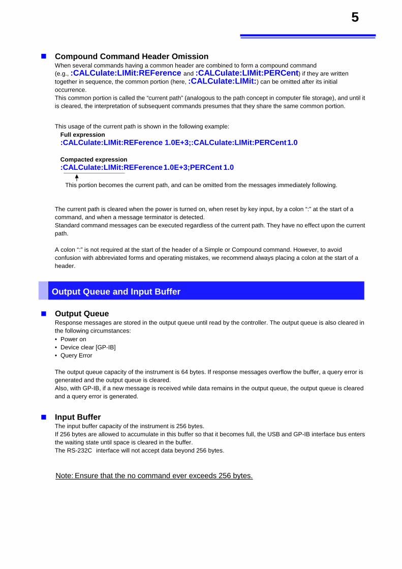
Compound Command Header Omission When several commands having a common header are combined to form a compound command (e.g., :CALCulate:LIMit:REFerence and :CALCulate:LIMit:PERCent ) if they are written together in sequence, the common portion (here, :CALCulate:LIMit:) can be omitted after its initial occurrence. This common portion is called the “current path” (analogous to the path concept in computer file storage), and until it is cleared, the interpretation of subsequent commands presumes that they share the same common portion.
This usage of the current path is shown in the following example:
Full expression
:CALCulate:LIMit:REFerence 1.0E+3;:CALCulate:LIMit:PERCent 1.0
Compacted expression
:CALCulate:LIMit:REFerence 1.0E+3;PERCent 1.0
This portion becomes the current path, and can be omitted from the messages immediately following.
The current path is cleared when the power is turned on, when reset by key input, by a colon “:” at the start of a command, and when a message terminator is detected. Standard command messages can be executed regardless of the current path. They have no effect upon the current path. A colon “:” is not required at the start of the header of a Simple or Compound command. However, to avoid confusion with abbreviated forms and operating mistakes, we recommend always placing a colon at the start of a header.
Output Queue and Input Buffer Output Queue
Response messages are stored in the output queue until read by the controller. The output queue is also cleared in the following circumstances: • Power on • Device clear [GP-IB] • Query Error
The output queue capacity of the instrument is 64 bytes. If response messages overflow the buffer, a query error is generated and the output queue is cleared. Also, with GP-IB, if a new message is received while data remains in the output queue, the output queue is cleared and a query error is generated.
Input Buffer
The input buffer capacity of the instrument is 256 bytes. If 256 bytes are allowed to accumulate in this buffer so that it becomes full, the USB and GP-IB interface bus enters the waiting state until space is cleared in the buffer. The RS-232C interface will not accept data beyond 256 bytes.
Note: Ensure that the no command ever exceeds 256 bytes.
6
Status Byte Register
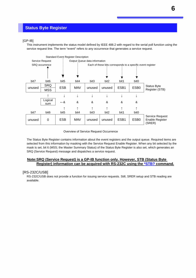
[GP-IB] This instrument implements the status model defined by IEEE 488.2 with regard to the serial poll function using the service request line. The term “event” refers to any occurrence that generates a service request.
Standard Event Register Description Service Request Output Queue data information SRQ occurrence Each of these bits corresponds to a specific event register
bit7 bit6 bit5 bit4 bit3 bit2 bit1 bit0
unused SRQ
ESB MAV unused unused ESB1 ESB0 Status Byte Register (STB) MSS
↑ ↓ ↓ ↓ ↓ ↓ ↓
Logical
sum ←& & & & & &
↑ ↑ ↑ ↑ ↑ ↑
bit7 bit6 bit5 bit4 bit3 bit2 bit1 bit0
unused 0 ESB MAV unused unused ESB1 ESB0 Service Request Enable Register (SRER)
Overview of Service Request Occurrence
The Status Byte Register contains information about the event registers and the output queue. Required items are selected from this information by masking with the Service Request Enable Register. When any bit selected by the mask is set, bit 6 (MSS; the Master Summary Status) of the Status Byte Register is also set, which generates an SRQ (Service Request) message and dispatches a service request.
Note: SRQ (Service Request) is a GP-IB function only. However, STB (Status Byte Register) information can be acquired with RS-232C using the *STB? command.
[RS-232C/USB] RS-232C/USB does not provide a function for issuing service requests. Still, SRER setup and STB reading are available.
7
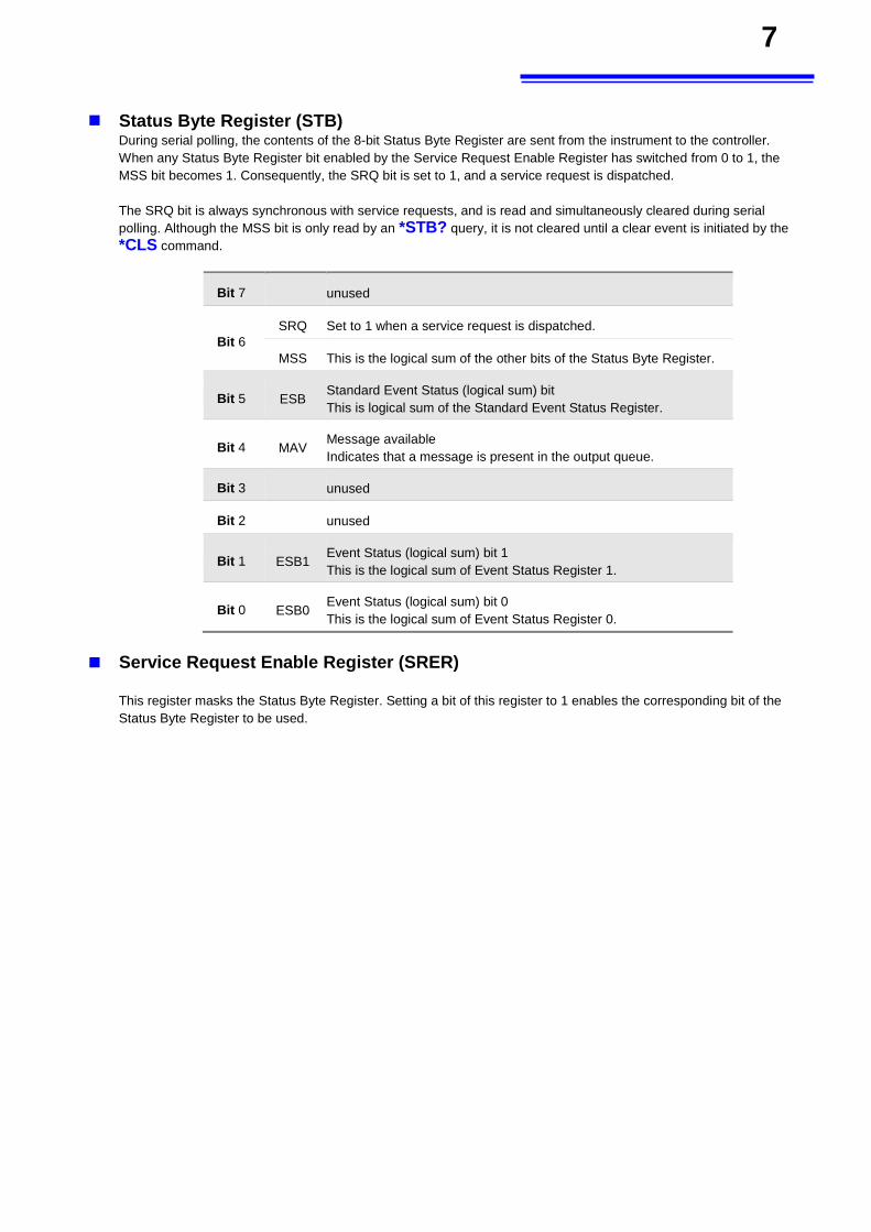
Status Byte Register (STB) During serial polling, the contents of the 8-bit Status Byte Register are sent from the instrument to the controller. When any Status Byte Register bit enabled by the Service Request Enable Register has switched from 0 to 1, the MSS bit becomes 1. Consequently, the SRQ bit is set to 1, and a service request is dispatched. The SRQ bit is always synchronous with service requests, and is read and simultaneously cleared during serial polling. Although the MSS bit is only read by an *STB? query, it is not cleared until a clear event is initiated by the *CLS command.
Bit 7 unused
Bit 6 SRQ Set to 1 when a service request is dispatched.
MSS This is the logical sum of the other bits of the Status Byte Register.
Bit 5 ESB Standard Event Status (logical sum) bit This is logical sum of the Standard Event Status Register.
Bit 4 MAV Message available Indicates that a message is present in the output queue.
Bit 3 unused
Bit 2 unused
Bit 1 ESB1 Event Status (logical sum) bit 1 This is the logical sum of Event Status Register 1.
Bit 0 ESB0 Event Status (logical sum) bit 0 This is the logical sum of Event Status Register 0.
Service Request Enable Register (SRER)
This register masks the Status Byte Register. Setting a bit of this register to 1 enables the corresponding bit of the Status Byte Register to be used.
8
Event Registers
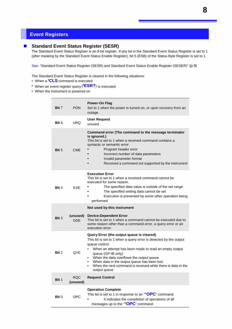
Standard Event Status Register (SESR)
The Standard Event Status Register is an 8-bit register. If any bit in the Standard Event Status Register is set to 1 (after masking by the Standard Event Status Enable Register), bit 5 (ESB) of the Status Byte Register is set to 1.
See: “Standard Event Status Register (SESR) and Standard Event Status Enable Register (SESER)” (p.9)
The Standard Event Status Register is cleared in the following situations: • When a *CLS command is executed • When an event register query (*ESR?) is executed • When the instrument is powered on
Bit 7 PON
Power-On Flag
Set to 1 when the power is turned on, or upon recovery from an outage.
Bit 6 URQ User Request unused
Bit 5 CME
Command error (The command to the message terminator is ignored.) This bit is set to 1 when a received command contains a syntactic or semantic error: • Program header error • Incorrect number of data parameters
• Invalid parameter format • Received a command not supported by the instrument
Bit 4 EXE
Execution Error This bit is set to 1 when a received command cannot be executed for some reason. • The specified data value is outside of the set range
• The specified setting data cannot be set • Execution is prevented by some other operation being
performed
Bit 3 (unused)
DDE
Not used by this instrument Device-Dependent Error This bit is set to 1 when a command cannot be executed due to some reason other than a command error, a query error or an execution error.
Bit 2 QYE
Query Error (the output queue is cleared) This bit is set to 1 when a query error is detected by the output queue control. • When an attempt has been made to read an empty output
queue (GP-IB only) • When the data overflows the output queue • When data in the output queue has been lost • When the next command is received while there is data in the
output queue
Bit 1 RQC
(unused) Request Control
Bit 0 OPC
Operation Complete
This bit is set to 1 in response to an “*OPC” command. • It indicates the completion of operations of all
messages up to the “*OPC” command
9
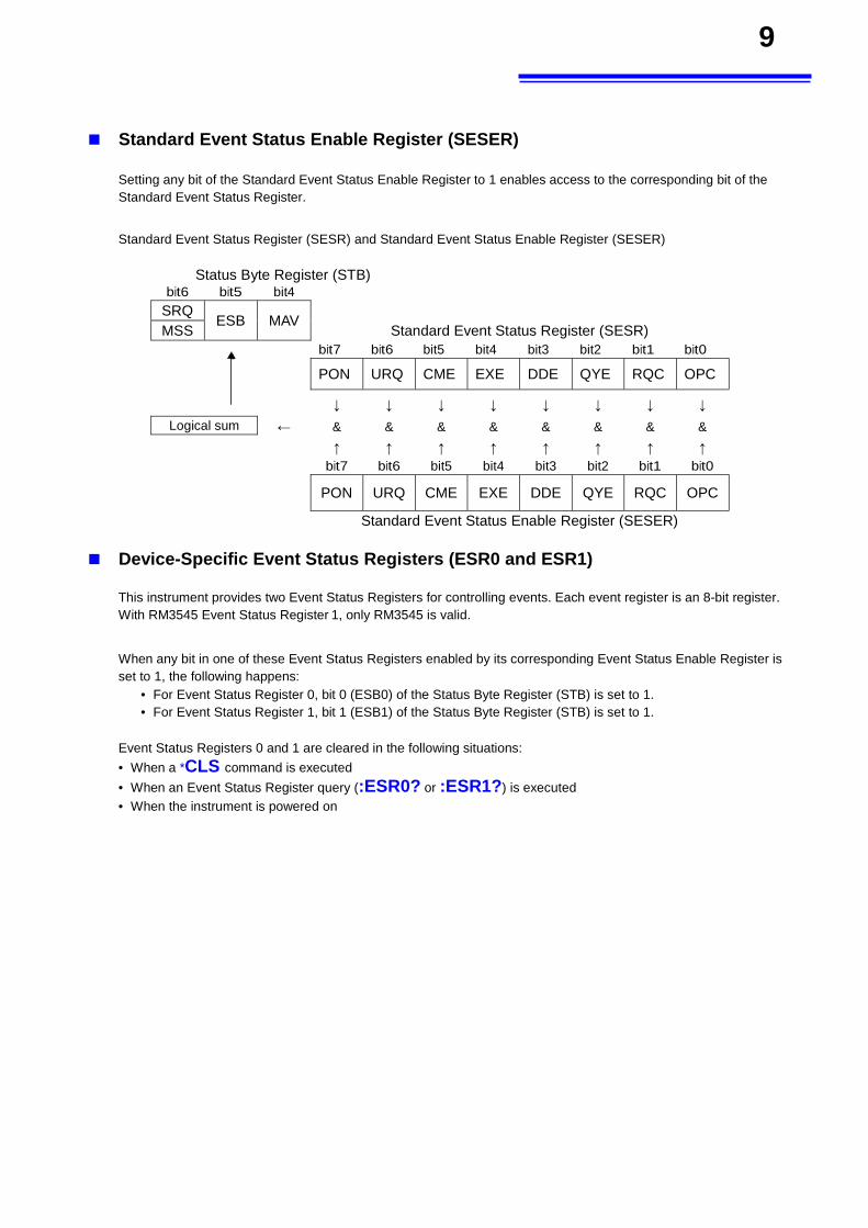
Standard Event Status Enable Register (SESER)
Setting any bit of the Standard Event Status Enable Register to 1 enables access to the corresponding bit of the Standard Event Status Register.
Standard Event Status Register (SESR) and Standard Event Status Enable Register (SESER)
Status Byte Register (STB)
bit6 bit5 bit4
SRQ ESB MAV
MSS Standard Event Status Register (SESR) bit7 bit6 bit5 bit4 bit3 bit2 bit1 bit0
PON URQ CME EXE DDE QYE RQC OPC
↓ ↓ ↓ ↓ ↓ ↓ ↓ ↓
Logical sum ← & & & & & & & &
↑ ↑ ↑ ↑ ↑ ↑ ↑ ↑ bit7 bit6 bit5 bit4 bit3 bit2 bit1 bit0
PON URQ CME EXE DDE QYE RQC OPC
Standard Event Status Enable Register (SESER)
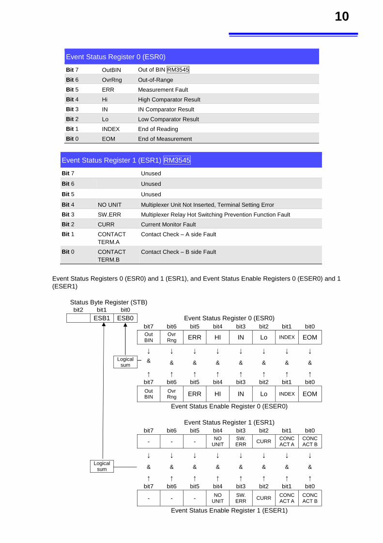
Device-Specific Event Status Registers (ESR0 and ESR1)
This instrument provides two Event Status Registers for controlling events. Each event register is an 8-bit register. With RM3545 Event Status Register 1, only RM3545 is valid.
When any bit in one of these Event Status Registers enabled by its corresponding Event Status Enable Register is set to 1, the following happens:
• For Event Status Register 0, bit 0 (ESB0) of the Status Byte Register (STB) is set to 1. • For Event Status Register 1, bit 1 (ESB1) of the Status Byte Register (STB) is set to 1.
Event Status Registers 0 and 1 are cleared in the following situations:
• When a *CLS command is executed
• When an Event Status Register query (:ESR0? or :ESR1?) is executed • When the instrument is powered on
10
Event Status Register 1 (ESR1) RM3545
Bit 7 Unused
Bit 6 Unused
Bit 5 Unused
Bit 4 NO UNIT Multiplexer Unit Not Inserted, Terminal Setting Error
Bit 3 SW.ERR Multiplexer Relay Hot Switching Prevention Function Fault
Bit 2 CURR Current Monitor Fault
Bit 1 CONTACT TERM.A
Contact Check – A side Fault
Bit 0 CONTACT
TERM.B
Contact Check – B side Fault
Event Status Registers 0 (ESR0) and 1 (ESR1), and Event Status Enable Registers 0 (ESER0) and 1 (ESER1)
Status Byte Register (STB)
bit2 bit1 bit0
ESB1 ESB0 Event Status Register 0 (ESR0) bit7 bit6 bit5 bit4 bit3 bit2 bit1 bit0
Out BIN
Ovr Rng ERR HI IN Lo INDEX EOM
↓ ↓ ↓ ↓ ↓ ↓ ↓ ↓
Logical sum
& & & & & & & &
↑ ↑ ↑ ↑ ↑ ↑ ↑ ↑ bit7 bit6 bit5 bit4 bit3 bit2 bit1 bit0
Out BIN
Ovr Rng ERR HI IN Lo INDEX EOM
Event Status Enable Register 0 (ESER0)
Event Status Register 1 (ESR1) bit7 bit6 bit5 bit4 bit3 bit2 bit1 bit0
- - - NO UNIT
SW. ERR
CURR CONCACT A
CONCACT B
↓ ↓ ↓ ↓ ↓ ↓ ↓ ↓
Logical
sum & & & & & & & &
↑ ↑ ↑ ↑ ↑ ↑ ↑ ↑ bit7 bit6 bit5 bit4 bit3 bit2 bit1 bit0
- - - NO UNIT
SW. ERR
CURR CONCACT A
CONCACT B
Event Status Enable Register 1 (ESER1)
Event Status Register 0 (ESR0)
Bit 7 OutBIN Out of BIN RM3545
Bit 6 OvrRng Out-of-Range
Bit 5 ERR Measurement Fault
Bit 4 Hi High Comparator Result
Bit 3 IN IN Comparator Result
Bit 2 Lo Low Comparator Result
Bit 1 INDEX End of Reading
Bit 0 EOM End of Measurement
11
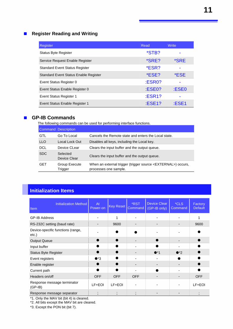
Register Reading and Writing
Register Read Write
Status Byte Register *STB? -
Service Request Enable Register *SRE? *SRE
Standard Event Status Register *ESR? - Standard Event Status Enable Register *ESE? *ESE
Event Status Register 0 :ESR0? - Event Status Enable Register 0 :ESE0? :ESE0
Event Status Register 1 :ESR1? - Event Status Enable Register 1 :ESE1? :ESE1
GP-IB Commands
The following commands can be used for performing interface functions.
Command Description
GTL Go To Local Cancels the Remote state and enters the Local state.
LLO Local Lock Out Disables all keys, including the Local key.
DCL Device CLear Clears the input buffer and the output queue.
SDC Selected Device Clear
Clears the input buffer and the output queue.
GET Group Execute Trigger
When an external trigger (trigger source <EXTERNAL>) occurs, processes one sample.
Initialization Items
Initialization Method
Item
At Power-on Key Reset
*RST Command
Device Clear (GP-IB only)
*CLS Command
Factory Default
GP-IB Address - 1 - - - 1
RS-232C setting (baud rate) - 9600 - - - 9600
Device-specific functions (range, etc.)
- - -
Output Queue - -
Input buffer - -
Status Byte Register - *1 *2
Event registers *3 - -
Enable register - - -
Current path - -
Headers on/off OFF OFF OFF - - OFF
Response message terminator (GP-IB)
LF+EOI LF+EOI - - - LF+EOI
Response message separator ; ; ; - - ;
*1. Only the MAV bit (bit 4) is cleared. *2. All bits except the MAV bit are cleared. *3. Except the PON bit (bit 7).
12
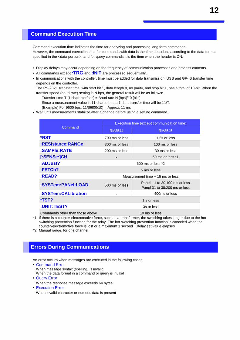
Command Execution Time
Command execution time indicates the time for analyzing and processing long form commands. However, the command execution time for commands with data is the time described according to the data format specified in the <data portion>, and for query commands it is the time when the header is ON.
• Display delays may occur depending on the frequency of communication processes and process contents. • All commands except *TRG and :INIT are processed sequentially. • In communications with the controller, time must be added for data transmission. USB and GP-IB transfer time
depends on the controller. The RS-232C transfer time, with start bit 1, data length 8, no parity, and stop bit 1, has a total of 10-bit. When the transfer speed (baud rate) setting is N bps, the general result will be as follows:
Transfer time T [1 character/sec] = Baud rate N [bps]/10 [bits] Since a measurement value is 11 characters, a 1 data transfer time will be 11/T. (Example) For 9600 bps, 11/(9600/10) = Approx. 11 ms
• Wait until measurements stabilize after a change before using a setting command.
Command Execution time (except communication time)
RM3544 RM3545
*RST 700 ms or less 1.5s or less
:RESistance:RANGe 300 ms or less 100 ms or less
:SAMPle:RATE 200 ms or less 30 ms or less
[:SENSe:]CH - 50 ms or less *1
:ADJust? 600 ms or less *2
:FETCh? 5 ms or less
:READ? Measurement time + 15 ms or less
:SYSTem:PANel:LOAD 500 ms or lessPanel 1 to 30:100 ms or less Panel 31 to 38:200 ms or less
:SYSTem:CALibration - 400ms or less
*TST? 1 s or less
:UNIT:TEST? 3s or less
Commands other than those above 10 ms or less
*1 If there is a counter-electromotive force, such as a transformer, the switching takes longer due to the hot switching prevention function for the relay. The hot switching prevention function is canceled when the counter-electromotive force is lost or a maximum 1 second + delay set value elapses.
*2 Manual range, for one channel
Errors During Communications
An error occurs when messages are executed in the following cases: • Command Error
When message syntax (spelling) is invalid When the data format in a command or query is invalid
• Query Error When the response message exceeds 64 bytes
• Execution Error When invalid character or numeric data is present
13
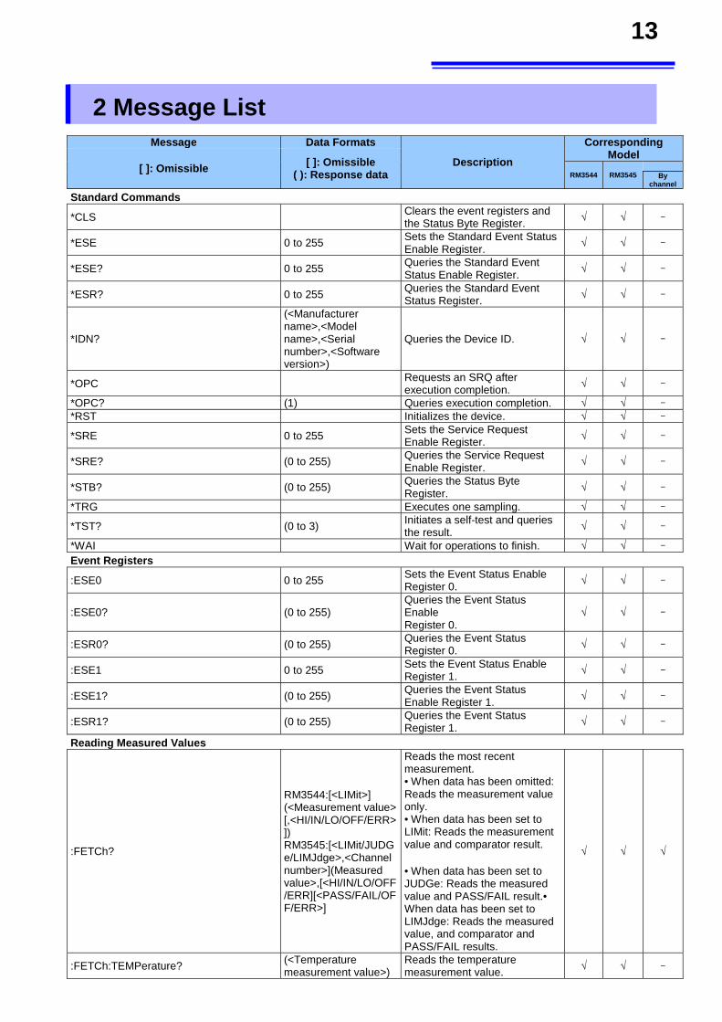
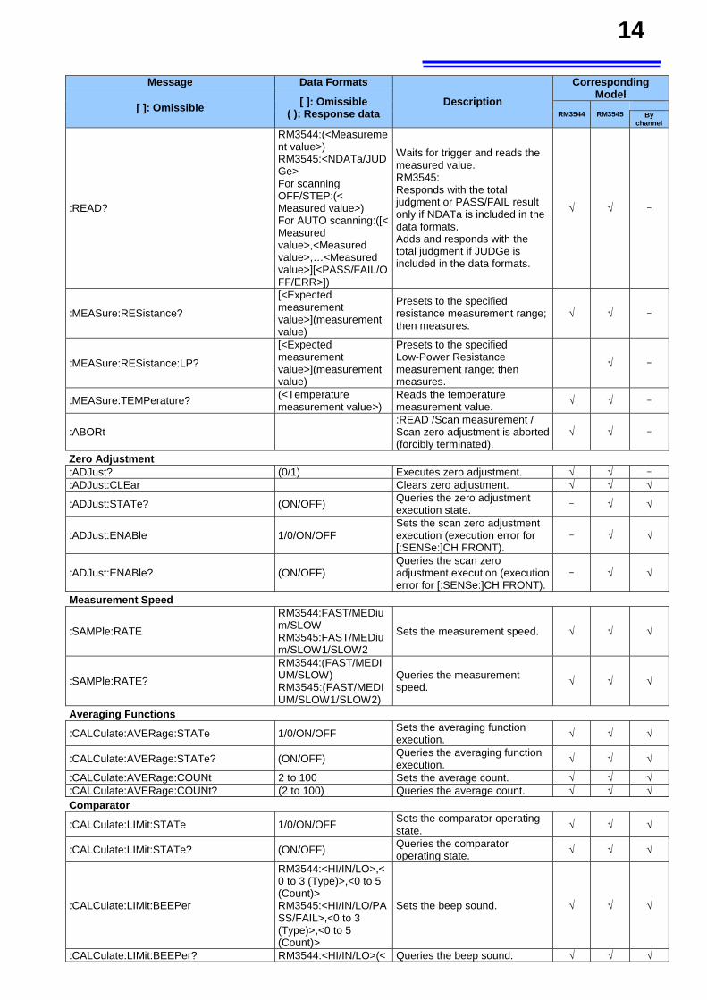
2 Message List
Message Data Formats
Description
Corresponding Model
[ ]: Omissible [ ]: Omissible ( ): Response data RM3544 RM3545
By channel
Standard Commands
*CLS Clears the event registers and the Status Byte Register. √ √ -
*ESE 0 to 255 Sets the Standard Event Status Enable Register.
√ √ -
*ESE? 0 to 255 Queries the Standard Event Status Enable Register. √ √ -
*ESR? 0 to 255 Queries the Standard Event Status Register. √ √ -
*IDN?
(<Manufacturer name>,<Model name>,<Serial number>,<Software version>)
Queries the Device ID. √ √ -
*OPC Requests an SRQ after execution completion. √ √ -
*OPC? (1) Queries execution completion. √ √ -
*RST Initializes the device. √ √ -
*SRE 0 to 255 Sets the Service Request Enable Register. √ √ -
*SRE? (0 to 255) Queries the Service Request Enable Register. √ √ -
*STB? (0 to 255) Queries the Status Byte Register. √ √ -
*TRG Executes one sampling. √ √ -
*TST? (0 to 3) Initiates a self-test and queries the result. √ √ -
*WAI Wait for operations to finish. √ √ -
Event Registers
:ESE0 0 to 255 Sets the Event Status Enable Register 0. √ √ -
:ESE0? (0 to 255) Queries the Event Status Enable Register 0.
√ √ -
:ESR0? (0 to 255) Queries the Event Status Register 0. √ √ -
:ESE1 0 to 255 Sets the Event Status Enable Register 1. √ √ -
:ESE1? (0 to 255) Queries the Event Status Enable Register 1. √ √ -
:ESR1? (0 to 255) Queries the Event Status Register 1. √ √ -
Reading Measured Values
:FETCh?
RM3544:[<LIMit>] (<Measurement value> [,<HI/IN/LO/OFF/ERR>]) RM3545:[<LIMit/JUDGe/LIMJdge>,<Channel number>](Measured value>,[<HI/IN/LO/OFF/ERR][<PASS/FAIL/OFF/ERR>]
Reads the most recent measurement. • When data has been omitted: Reads the measurement value only. • When data has been set to LIMit: Reads the measurement value and comparator result. • When data has been set to JUDGe: Reads the measured value and PASS/FAIL result.• When data has been set to LIMJdge: Reads the measured value, and comparator and PASS/FAIL results.
√ √ √
:FETCh:TEMPerature? (<Temperature measurement value>)
Reads the temperature measurement value. √ √ -
14
Message Data Formats
Description
Corresponding Model
[ ]: Omissible [ ]: Omissible ( ): Response data RM3544 RM3545
By channel
:READ?
RM3544:(<Measurement value>) RM3545:<NDATa/JUDGe> For scanning OFF/STEP:(< Measured value>) For AUTO scanning:([< Measured value>,<Measured value>,…<Measured value>][<PASS/FAIL/OFF/ERR>])
Waits for trigger and reads the measured value. RM3545: Responds with the total judgment or PASS/FAIL result only if NDATa is included in the data formats. Adds and responds with the total judgment if JUDGe is included in the data formats.
√ √ -
:MEASure:RESistance?
[<Expected measurement value>](measurement value)
Presets to the specified resistance measurement range; then measures.
√ √ -
:MEASure:RESistance:LP?
[<Expected measurement value>](measurement value)
Presets to the specified Low-Power Resistance measurement range; then measures.
√ -
:MEASure:TEMPerature? (<Temperature measurement value>)
Reads the temperature measurement value.
√ √ -
:ABORt :READ /Scan measurement / Scan zero adjustment is aborted (forcibly terminated).
√ √ -
Zero Adjustment
:ADJust? (0/1) Executes zero adjustment. √ √ -
:ADJust:CLEar Clears zero adjustment. √ √ √
:ADJust:STATe? (ON/OFF) Queries the zero adjustment execution state. - √ √
:ADJust:ENABle 1/0/ON/OFF Sets the scan zero adjustment execution (execution error for [:SENSe:]CH FRONT).
- √ √
:ADJust:ENABle? (ON/OFF) Queries the scan zero adjustment execution (execution error for [:SENSe:]CH FRONT).
- √ √
Measurement Speed
:SAMPle:RATE
RM3544:FAST/MEDium/SLOW RM3545:FAST/MEDium/SLOW1/SLOW2
Sets the measurement speed. √ √ √
:SAMPle:RATE?
RM3544:(FAST/MEDIUM/SLOW) RM3545:(FAST/MEDIUM/SLOW1/SLOW2)
Queries the measurement speed. √ √ √
Averaging Functions
:CALCulate:AVERage:STATe 1/0/ON/OFF Sets the averaging function execution. √ √ √
:CALCulate:AVERage:STATe? (ON/OFF) Queries the averaging function execution. √ √ √
:CALCulate:AVERage:COUNt 2 to 100 Sets the average count. √ √ √:CALCulate:AVERage:COUNt? (2 to 100) Queries the average count. √ √ √Comparator
:CALCulate:LIMit:STATe 1/0/ON/OFF Sets the comparator operating state. √ √ √
:CALCulate:LIMit:STATe? (ON/OFF) Queries the comparator operating state. √ √ √
:CALCulate:LIMit:BEEPer
RM3544:<HI/IN/LO>,<0 to 3 (Type)>,<0 to 5 (Count)> RM3545:<HI/IN/LO/PASS/FAIL>,<0 to 3 (Type)>,<0 to 5 (Count)>
Sets the beep sound. √ √ √
:CALCulate:LIMit:BEEPer? RM3544:<HI/IN/LO>(< Queries the beep sound. √ √ √
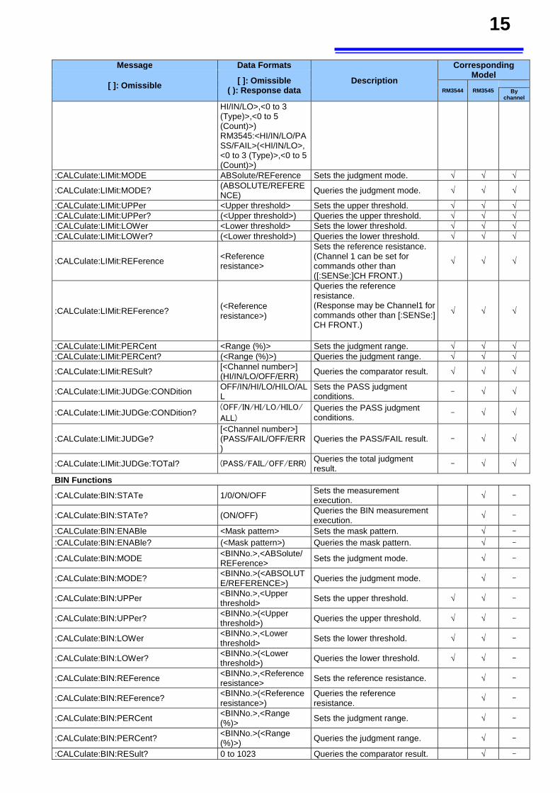
15
Message Data Formats
Description
Corresponding Model
[ ]: Omissible [ ]: Omissible ( ): Response data RM3544 RM3545
By channel
HI/IN/LO>,<0 to 3 (Type)>,<0 to 5 (Count)>) RM3545:<HI/IN/LO/PASS/FAIL>(<HI/IN/LO>,<0 to 3 (Type)>,<0 to 5 (Count)>)
:CALCulate:LIMit:MODE ABSolute/REFerence Sets the judgment mode. √ √ √
:CALCulate:LIMit:MODE? (ABSOLUTE/REFERENCE) Queries the judgment mode. √ √ √
:CALCulate:LIMit:UPPer <Upper threshold> Sets the upper threshold. √ √ √:CALCulate:LIMit:UPPer? (<Upper threshold>) Queries the upper threshold. √ √ √:CALCulate:LIMit:LOWer <Lower threshold> Sets the lower threshold. √ √ √:CALCulate:LIMit:LOWer? (<Lower threshold>) Queries the lower threshold. √ √ √
:CALCulate:LIMit:REFerence <Reference resistance>
Sets the reference resistance. (Channel 1 can be set for commands other than ([:SENSe:]CH FRONT.)
√ √ √
:CALCulate:LIMit:REFerence? (<Reference resistance>)
Queries the reference resistance. (Response may be Channel1 for commands other than [:SENSe:] CH FRONT.)
√ √ √
:CALCulate:LIMit:PERCent <Range (%)> Sets the judgment range. √ √ √:CALCulate:LIMit:PERCent? (<Range (%)>) Queries the judgment range. √ √ √
:CALCulate:LIMit:RESult? [<Channel number>] (HI/IN/LO/OFF/ERR) Queries the comparator result. √ √ √
:CALCulate:LIMit:JUDGe:CONDition OFF/IN/HI/LO/HILO/ALL
Sets the PASS judgment conditions.
- √ √
:CALCulate:LIMit:JUDGe:CONDition? (OFF/IN/HI/LO/HILO/
ALL) Queries the PASS judgment conditions. - √ √
:CALCulate:LIMit:JUDGe? [<Channel number>] (PASS/FAIL/OFF/ERR)
Queries the PASS/FAIL result. - √ √
:CALCulate:LIMit:JUDGe:TOTal? (PASS/FAIL/OFF/ERR)Queries the total judgment result. - √ √
BIN Functions
:CALCulate:BIN:STATe 1/0/ON/OFF Sets the measurement execution.
√ -
:CALCulate:BIN:STATe? (ON/OFF) Queries the BIN measurement execution.
√ -
:CALCulate:BIN:ENABle <Mask pattern> Sets the mask pattern. √ -
:CALCulate:BIN:ENABle? (<Mask pattern>) Queries the mask pattern. √ -
:CALCulate:BIN:MODE <BINNo.>,<ABSolute/REFerence> Sets the judgment mode. √ -
:CALCulate:BIN:MODE? <BINNo.>(<ABSOLUTE/REFERENCE>) Queries the judgment mode. √ -
:CALCulate:BIN:UPPer <BINNo.>,<Upper threshold> Sets the upper threshold. √ √ -
:CALCulate:BIN:UPPer? <BINNo.>(<Upper threshold>) Queries the upper threshold. √ √ -
:CALCulate:BIN:LOWer <BINNo.>,<Lower threshold> Sets the lower threshold. √ √ -
:CALCulate:BIN:LOWer? <BINNo.>(<Lower threshold>) Queries the lower threshold. √ √ -
:CALCulate:BIN:REFerence <BINNo.>,<Reference resistance> Sets the reference resistance. √ -
:CALCulate:BIN:REFerence? <BINNo.>(<Reference resistance>)
Queries the reference resistance.
√ -
:CALCulate:BIN:PERCent <BINNo.>,<Range (%)> Sets the judgment range. √ -
:CALCulate:BIN:PERCent? <BINNo.>(<Range (%)>) Queries the judgment range. √ -
:CALCulate:BIN:RESult? 0 to 1023 Queries the comparator result. √ -
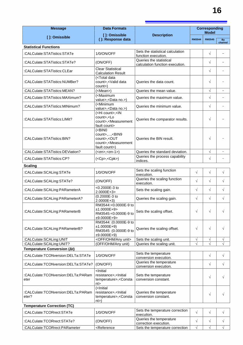
16
Message Data Formats
Description
Corresponding Model
[ ]: Omissible [ ]: Omissible ( ): Response data RM3544 RM3545
By channel
Statistical Functions
:CALCulate:STATistics:STATe 1/0/ON/OFF Sets the statistical calculation function execution. √ -
:CALCulate:STATistics:STATe? (ON/OFF) Queries the statistical calculation function execution.
√ -
:CALCulate:STATistics:CLEar Clear Statistical Calculation Result √ -
:CALCulate:STATistics:NUMBer? (<Total data count>,<Valid data count>)
Queries the data count. √ -
:CALCulate:STATistics:MEAN? (<Mean>) Queries the mean value. √ -
:CALCulate:STATistics:MAXimum? (<Maximum value>,<Data no.>) Queries the maximum value. √ -
:CALCulate:STATistics:MINimum? (<Minimum value>,<Data no.>) Queries the minimum value. √ -
:CALCulate:STATistics:LIMit?
(<Hi count>,<IN count>,<Lo count>,<Measurement fault count>
Queries the comparator results. √ -
:CALCulate:STATistics:BIN?
(<BIN0 count>,...,<BIN9 count>,<OUT count>,<Measurement fault count>)
Queries the BIN result. √ -
:CALCulate:STATistics:DEViation? (<σn>,<σn-1>) Queries the standard deviation. √ -
:CALCulate:STATistics:CP? (<Cp>,<Cpk>) Queries the process capability indices.
√ -
Scaling
:CALCulate:SCALing:STATe 1/0/ON/OFF Sets the scaling function execution.
√ √ √
:CALCulate:SCALing:STATe? (ON/OFF) Queries the scaling function execution. √ √ √
:CALCulate:SCALing:PARameterA <0.2000E-3 to 2.0000E+3> Sets the scaling gain. √ √ √
:CALCulate:SCALing:PARameterA? (0.2000E-3 to 2.0000E+3) Queries the scaling gain. √ √ √
:CALCulate:SCALing:PARameterB
RM3544:<0.0000E-9 to ±1.0000E+9> RM3545:<0.0000E-9 to ±9.0000E+9>
Sets the scaling offset. √ √ √
:CALCulate:SCALing:PARameterB?
RM3544: (0.0000E-9 to ±1.0000E+9) RM3545: (0.0000E-9 to ±9.0000E+9)
Queries the scaling offset. √ √ √
:CALCulate:SCALing:UNIT <OFF/OHM/Any unit> Sets the scaling unit. √ √ √:CALCulate:SCALing:UNIT? (OFF/OHM/Any unit) Queries the scaling unit. √ √ √Temperature Conversion (∆t)
:CALCulate:TCONversion:DELTa:STATe 1/0/ON/OFF Sets the temperature conversion execution. √ √
:CALCulate:TCONversion:DELTa:STATe? (ON/OFF) Queries the temperature conversion execution.
√ √
:CALCulate:TCONversion:DELTa:PARameter
<Initial resistance>,<Initial temperature>,<Constant>
Sets the temperature conversion constant.
√ √
:CALCulate:TCONversion:DELTa:PARameter?
(<Initial resistance>,<Initial temperature>,<Constant>)
Queries the temperature conversion constant.
√ √
Temperature Correction (TC)
:CALCulate:TCORrect:STATe 1/0/ON/OFF Sets the temperature correction execution. √ √ √
:CALCulate:TCORrect:STATe? (ON/OFF) Queries the temperature correction execution. √ √ √
:CALCulate:TCORrect:PARameter <Reference Sets the temperature correction √ √ √
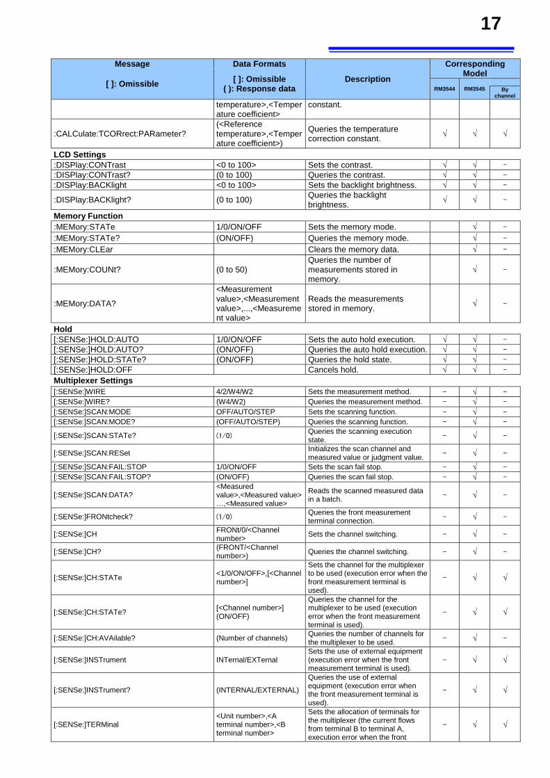
17
Message Data Formats
Description
Corresponding Model
[ ]: Omissible [ ]: Omissible ( ): Response data RM3544 RM3545
By channel
temperature>,<Temperature coefficient>
constant.
:CALCulate:TCORrect:PARameter? (<Reference temperature>,<Temperature coefficient>)
Queries the temperature correction constant. √ √ √
LCD Settings
:DISPlay:CONTrast <0 to 100> Sets the contrast. √ √ -
:DISPlay:CONTrast? (0 to 100) Queries the contrast. √ √ -
:DISPlay:BACKlight <0 to 100> Sets the backlight brightness. √ √ -
:DISPlay:BACKlight? (0 to 100) Queries the backlight brightness.
√ √ -
Memory Function
:MEMory:STATe 1/0/ON/OFF Sets the memory mode. √ -
:MEMory:STATe? (ON/OFF) Queries the memory mode. √ -
:MEMory:CLEar Clears the memory data. √ -
:MEMory:COUNt? (0 to 50) Queries the number of measurements stored in memory.
√ -
:MEMory:DATA?
<Measurement value>,<Measurement value>,...,<Measurement value>
Reads the measurements stored in memory.
√ -
Hold
[:SENSe:]HOLD:AUTO 1/0/ON/OFF Sets the auto hold execution. √ √ -
[:SENSe:]HOLD:AUTO? (ON/OFF) Queries the auto hold execution. √ √ -
[:SENSe:]HOLD:STATe? (ON/OFF) Queries the hold state. √ √ -
[:SENSe:]HOLD:OFF Cancels hold. √ √ -
Multiplexer Settings [:SENSe:]WIRE 4/2/W4/W2 Sets the measurement method. - √ -
[:SENSe:]WIRE? (W4/W2) Queries the measurement method. - √ -
[:SENSe:]SCAN:MODE OFF/AUTO/STEP Sets the scanning function. - √ -
[:SENSe:]SCAN:MODE? (OFF/AUTO/STEP) Queries the scanning function. - √ -
[:SENSe:]SCAN:STATe? (1/0) Queries the scanning execution state. - √ -
[:SENSe:]SCAN:RESet Initializes the scan channel and measured value or judgment value. - √ -
[:SENSe:]SCAN:FAIL:STOP 1/0/ON/OFF Sets the scan fail stop. - √ -
[:SENSe:]SCAN:FAIL:STOP? (ON/OFF) Queries the scan fail stop. - √ -
[:SENSe:]SCAN:DATA?
<Measured value>,<Measured value> …,<Measured value>
Reads the scanned measured data in a batch. - √ -
[:SENSe:]FRONtcheck? (1/0) Queries the front measurement terminal connection. - √ -
[:SENSe:]CH FRONt/0/<Channel number>
Sets the channel switching. - √ -
[:SENSe:]CH? (FRONT/<Channel number>) Queries the channel switching. - √ -
[:SENSe:]CH:STATe <1/0/ON/OFF>,[<Channel number>]
Sets the channel for the multiplexer to be used (execution error when the front measurement terminal is used).
- √ √
[:SENSe:]CH:STATe? [<Channel number>] (ON/OFF)
Queries the channel for the multiplexer to be used (execution error when the front measurement terminal is used).
- √ √
[:SENSe:]CH:AVAilable? (Number of channels) Queries the number of channels for the multiplexer to be used. - √ -
[:SENSe:]INSTrument INTernal/EXTernal Sets the use of external equipment (execution error when the front measurement terminal is used).
- √ √
[:SENSe:]INSTrument? (INTERNAL/EXTERNAL)
Queries the use of external equipment (execution error when the front measurement terminal is used).
- √ √
[:SENSe:]TERMinal <Unit number>,<A terminal number>,<B terminal number>
Sets the allocation of terminals for the multiplexer (the current flows from terminal B to terminal A, execution error when the front
- √ √
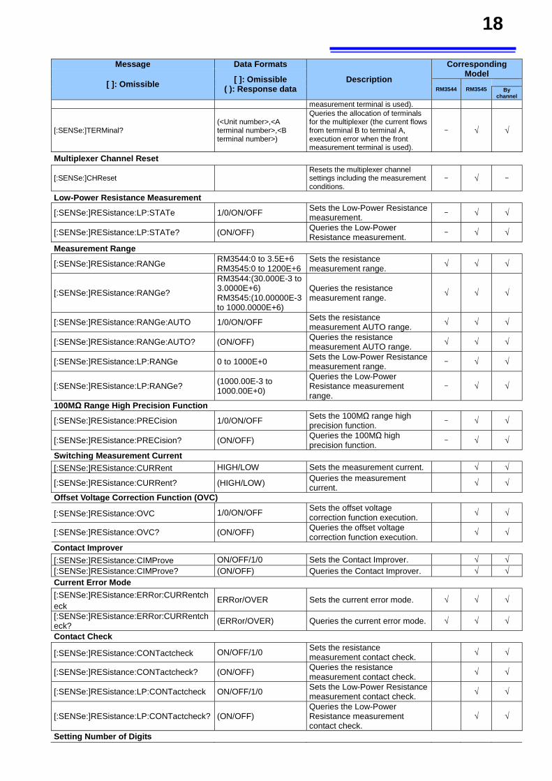
18
Message Data Formats
Description
Corresponding Model
[ ]: Omissible [ ]: Omissible ( ): Response data RM3544 RM3545
By channel
measurement terminal is used).
[:SENSe:]TERMinal? (<Unit number>,<A terminal number>,<B terminal number>)
Queries the allocation of terminals for the multiplexer (the current flows from terminal B to terminal A, execution error when the front measurement terminal is used).
- √ √
Multiplexer Channel Reset
[:SENSe:]CHReset Resets the multiplexer channel settings including the measurement conditions.
- √ -
Low-Power Resistance Measurement
[:SENSe:]RESistance:LP:STATe 1/0/ON/OFF Sets the Low-Power Resistance measurement.
- √ √
[:SENSe:]RESistance:LP:STATe? (ON/OFF) Queries the Low-Power Resistance measurement.
- √ √
Measurement Range
[:SENSe:]RESistance:RANGe RM3544:0 to 3.5E+6 RM3545:0 to 1200E+6
Sets the resistance measurement range. √ √ √
[:SENSe:]RESistance:RANGe?
RM3544:(30.000E-3 to 3.0000E+6) RM3545:(10.00000E-3 to 1000.0000E+6)
Queries the resistance measurement range.
√ √ √
[:SENSe:]RESistance:RANGe:AUTO 1/0/ON/OFF Sets the resistance measurement AUTO range. √ √ √
[:SENSe:]RESistance:RANGe:AUTO? (ON/OFF) Queries the resistance measurement AUTO range. √ √ √
[:SENSe:]RESistance:LP:RANGe 0 to 1000E+0 Sets the Low-Power Resistance measurement range.
- √ √
[:SENSe:]RESistance:LP:RANGe? (1000.00E-3 to 1000.00E+0)
Queries the Low-Power Resistance measurement range.
- √ √
100MΩ Range High Precision Function
[:SENSe:]RESistance:PRECision 1/0/ON/OFF Sets the 100MΩ range high precision function. - √ √
[:SENSe:]RESistance:PRECision? (ON/OFF) Queries the 100MΩ high precision function. - √ √
Switching Measurement Current
[:SENSe:]RESistance:CURRent HIGH/LOW Sets the measurement current. √ √
[:SENSe:]RESistance:CURRent? (HIGH/LOW) Queries the measurement current.
√ √ Offset Voltage Correction Function (OVC)
[:SENSe:]RESistance:OVC 1/0/ON/OFF Sets the offset voltage correction function execution.
√ √
[:SENSe:]RESistance:OVC? (ON/OFF) Queries the offset voltage correction function execution.
√ √ Contact Improver
[:SENSe:]RESistance:CIMProve ON/OFF/1/0 Sets the Contact Improver. √ √[:SENSe:]RESistance:CIMProve? (ON/OFF) Queries the Contact Improver. √ √Current Error Mode
[:SENSe:]RESistance:ERRor:CURRentcheck
ERRor/OVER Sets the current error mode. √ √ √ [:SENSe:]RESistance:ERRor:CURRentcheck?
(ERRor/OVER) Queries the current error mode. √ √ √ Contact Check
[:SENSe:]RESistance:CONTactcheck ON/OFF/1/0 Sets the resistance measurement contact check.
√ √
[:SENSe:]RESistance:CONTactcheck? (ON/OFF) Queries the resistance measurement contact check.
√ √
[:SENSe:]RESistance:LP:CONTactcheck ON/OFF/1/0 Sets the Low-Power Resistance measurement contact check. √ √
[:SENSe:]RESistance:LP:CONTactcheck? (ON/OFF) Queries the Low-Power Resistance measurement contact check.
√ √
Setting Number of Digits
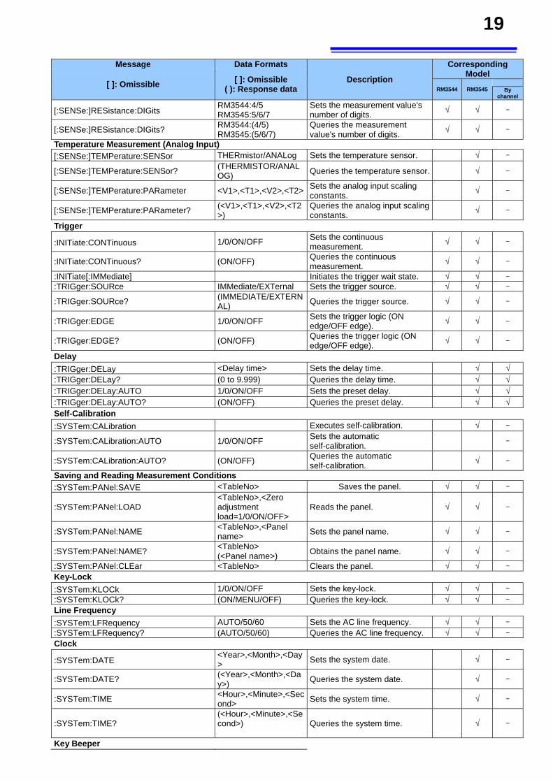
19
Message Data Formats
Description
Corresponding Model
[ ]: Omissible [ ]: Omissible ( ): Response data RM3544 RM3545
By channel
[:SENSe:]RESistance:DIGits RM3544:4/5 RM3545:5/6/7
Sets the measurement value's number of digits. √ √ -
[:SENSe:]RESistance:DIGits? RM3544:(4/5) RM3545:(5/6/7)
Queries the measurement value's number of digits. √ √ -
Temperature Measurement (Analog Input) [:SENSe:]TEMPerature:SENSor THERmistor/ANALog Sets the temperature sensor. √ -
[:SENSe:]TEMPerature:SENSor? (THERMISTOR/ANALOG) Queries the temperature sensor. √ -
[:SENSe:]TEMPerature:PARameter <V1>,<T1>,<V2>,<T2> Sets the analog input scaling constants.
√ -
[:SENSe:]TEMPerature:PARameter? (<V1>,<T1>,<V2>,<T2>)
Queries the analog input scaling constants. √ -
Trigger
:INITiate:CONTinuous 1/0/ON/OFF Sets the continuous measurement.
√ √ -
:INITiate:CONTinuous? (ON/OFF) Queries the continuous measurement. √ √ -
:INITiate[:IMMediate] Initiates the trigger wait state. √ √ -
:TRIGger:SOURce IMMediate/EXTernal Sets the trigger source. √ √ -
:TRIGger:SOURce? (IMMEDIATE/EXTERNAL) Queries the trigger source. √ √ -
:TRIGger:EDGE 1/0/ON/OFF Sets the trigger logic (ON edge/OFF edge). √ √ -
:TRIGger:EDGE? (ON/OFF) Queries the trigger logic (ON edge/OFF edge). √ √ -
Delay
:TRIGger:DELay <Delay time> Sets the delay time. √ √:TRIGger:DELay? (0 to 9.999) Queries the delay time. √ √:TRIGger:DELay:AUTO 1/0/ON/OFF Sets the preset delay. √ √:TRIGger:DELay:AUTO? (ON/OFF) Queries the preset delay. √ √Self-Calibration
:SYSTem:CALibration Executes self-calibration. √ -
:SYSTem:CALibration:AUTO 1/0/ON/OFF Sets the automatic self-calibration. -
:SYSTem:CALibration:AUTO? (ON/OFF) Queries the automatic self-calibration.
√ - Saving and Reading Measurement Conditions
:SYSTem:PANel:SAVE <TableNo> Saves the panel. √ √ -
:SYSTem:PANel:LOAD <TableNo>,<Zero adjustment load=1/0/ON/OFF>
Reads the panel. √ √ -
:SYSTem:PANel:NAME <TableNo>,<Panel name> Sets the panel name. √ √ -
:SYSTem:PANel:NAME? <TableNo> (<Panel name>) Obtains the panel name. √ √ -
:SYSTem:PANel:CLEar <TableNo> Clears the panel. √ √ -
Key-Lock
:SYSTem:KLOCk 1/0/ON/OFF Sets the key-lock. √ √ -
:SYSTem:KLOCk? (ON/MENU/OFF) Queries the key-lock. √ √ -
Line Frequency
:SYSTem:LFRequency AUTO/50/60 Sets the AC line frequency. √ √ -
:SYSTem:LFRequency? (AUTO/50/60) Queries the AC line frequency. √ √ -
Clock
:SYSTem:DATE <Year>,<Month>,<Day>
Sets the system date. √ -
:SYSTem:DATE? (<Year>,<Month>,<Day>)
Queries the system date. √ -
:SYSTem:TIME <Hour>,<Minute>,<Second>
Sets the system time. √ -
:SYSTem:TIME? (<Hour>,<Minute>,<Second>)
Queries the system time. √ -
Key Beeper
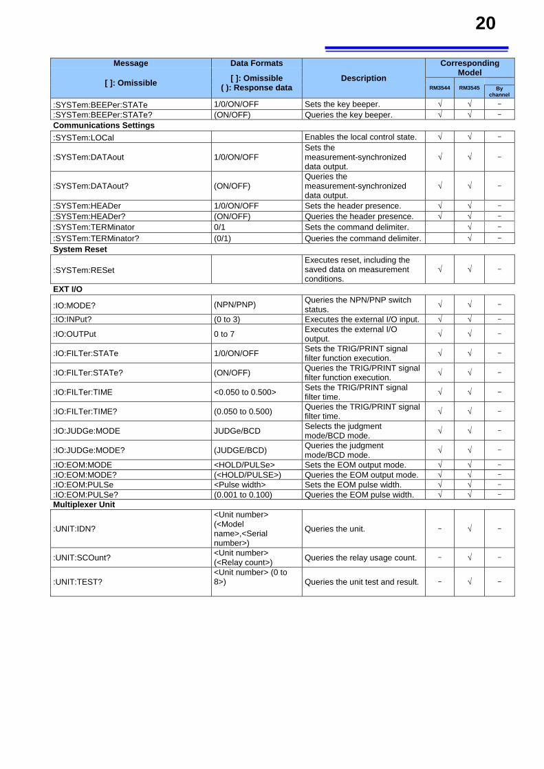
20
Message Data Formats
Description
Corresponding Model
[ ]: Omissible [ ]: Omissible ( ): Response data RM3544 RM3545
By channel
:SYSTem:BEEPer:STATe 1/0/ON/OFF Sets the key beeper. √ √ -
:SYSTem:BEEPer:STATe? (ON/OFF) Queries the key beeper. √ √ -
Communications Settings
:SYSTem:LOCal Enables the local control state. √ √ -
:SYSTem:DATAout 1/0/ON/OFF Sets the measurement-synchronized data output.
√ √ -
:SYSTem:DATAout? (ON/OFF) Queries the measurement-synchronized data output.
√ √ -
:SYSTem:HEADer 1/0/ON/OFF Sets the header presence. √ √ -
:SYSTem:HEADer? (ON/OFF) Queries the header presence. √ √ -
:SYSTem:TERMinator 0/1 Sets the command delimiter. √ -
:SYSTem:TERMinator? (0/1) Queries the command delimiter. √ -
System Reset
:SYSTem:RESet Executes reset, including the saved data on measurement conditions.
√ √ -
EXT I/O
:IO:MODE? (NPN/PNP) Queries the NPN/PNP switch status.
√ √ - :IO:INPut? (0 to 3) Executes the external I/O input. √ √ -
:IO:OUTPut 0 to 7 Executes the external I/O output. √ √ -
:IO:FILTer:STATe 1/0/ON/OFF Sets the TRIG/PRINT signal filter function execution. √ √ -
:IO:FILTer:STATe? (ON/OFF) Queries the TRIG/PRINT signal filter function execution. √ √ -
:IO:FILTer:TIME <0.050 to 0.500> Sets the TRIG/PRINT signal filter time. √ √ -
:IO:FILTer:TIME? (0.050 to 0.500) Queries the TRIG/PRINT signal filter time. √ √ -
:IO:JUDGe:MODE JUDGe/BCD Selects the judgment mode/BCD mode. √ √ -
:IO:JUDGe:MODE? (JUDGE/BCD) Queries the judgment mode/BCD mode. √ √ -
:IO:EOM:MODE <HOLD/PULSe> Sets the EOM output mode. √ √ -
:IO:EOM:MODE? (<HOLD/PULSE>) Queries the EOM output mode. √ √ -
:IO:EOM:PULSe <Pulse width> Sets the EOM pulse width. √ √ -
:IO:EOM:PULSe? (0.001 to 0.100) Queries the EOM pulse width. √ √ -
Multiplexer Unit
:UNIT:IDN? <Unit number> (<Model name>,<Serial number>)
Queries the unit. - √ -
:UNIT:SCOunt? <Unit number> (<Relay count>) Queries the relay usage count. - √ -
:UNIT:TEST? <Unit number> (0 to 8>)
Queries the unit test and result. - √ -
21
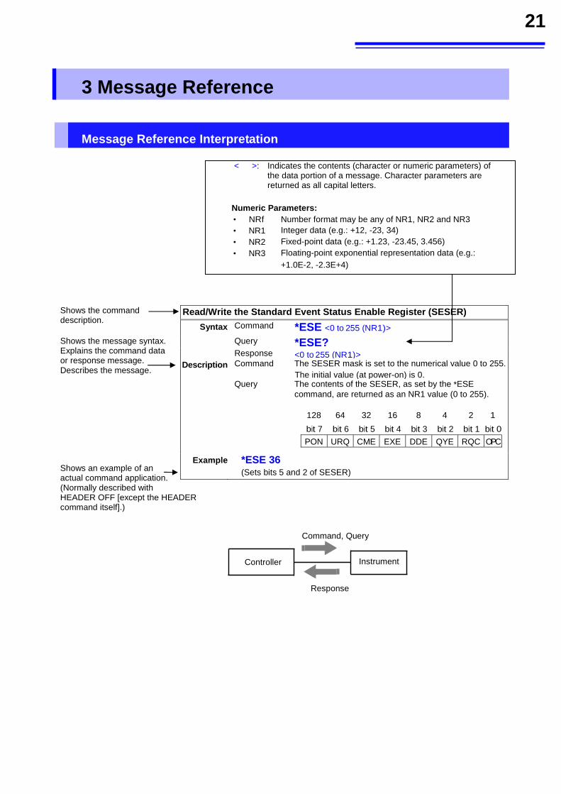
3 Message Reference
Message Reference Interpretation
< >: Indicates the contents (character or numeric parameters) of
the data portion of a message. Character parameters are returned as all capital letters.
Numeric Parameters: • NRf Number format may be any of NR1, NR2 and NR3
• NR1 Integer data (e.g.: +12, -23, 34) • NR2 Fixed-point data (e.g.: +1.23, -23.45, 3.456) • NR3 Floating-point exponential representation data (e.g.:
+1.0E-2, -2.3E+4)
Shows the command description. Shows the message syntax. Explains the command data or response message. Describes the message.
Shows an example of an actual command application. (Normally described with HEADER OFF [except the HEADER command itself].)
Read/Write the Standard Event Status Enable Register (SESER)
Syntax Command *ESE <0 to 255 (NR1)>
Query *ESE? Response <0 to 255 (NR1)>
Description Command The SESER mask is set to the numerical value 0 to 255. The initial value (at power-on) is 0.
Query The contents of the SESER, as set by the *ESE command, are returned as an NR1 value (0 to 255).
128 64 32 16 8 4 2 1 bit 7 bit 6 bit 5 bit 4 bit 3 bit 2 bit 1 bit 0
PON URQ CME EXE DDE QYE RQC OPC
Example *ESE 36 (Sets bits 5 and 2 of SESER)
Command, Query
Response
Controller Instrument
22
Standard Commands
(1) System Data Command
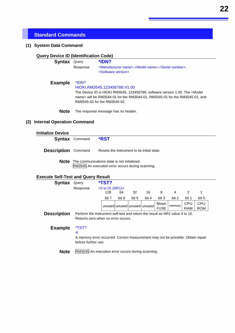
Query Device ID (Identification Code) Syntax Query *IDN?
Response <Manufacturer name>,<Model name>,<Serial number>, <Software version>
Example *IDN?
HIOKI,RM3545,123456789,V1.00 The Device ID is HIOKI RM3545, 123456789, software version 1.00. The <Model name> will be RM3544-01 for the RM3544-01, RM3545-01 for the RM3545-01, and RM3545-02 for the RM3545-02.
Note The response message has no header.
(2) Internal Operation Command
Initialize Device Syntax Command *RST
Description Command Resets the instrument to its initial state.
Note The communications state is not initialized.
RM3545 An execution error occurs during scanning.
Execute Self-Test and Query Result
Syntax Query *TST? Response <0 to 15 (NR1)>
128 64 32 16 8 4 2 1 bit 7 bit 6 bit 5 bit 4 bit 3 bit 2 bit 1 bit 0
unused unused unused unusedBlown FUSE
memory CPU RAM
CPU ROM
Description Perform the instrument self-test and return the result as NR1 value 0 to 15. Returns zero when no error occurs.
Example *TST? 4 A memory error occurred. Correct measurement may not be possible. Obtain repair before further use.
Note RM3545 An execution error occurs during scanning.
23
(3) Synchronization Commands
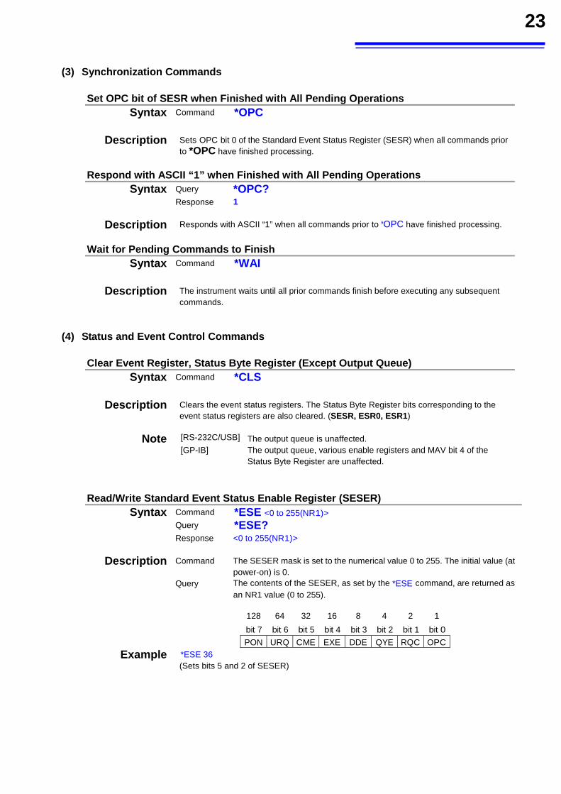
Set OPC bit of SESR when Finished with All Pending Operations Syntax Command *OPC
Description Sets OPC bit 0 of the Standard Event Status Register (SESR) when all commands prior
to *OPC have finished processing.
Respond with ASCII “1” when Finished with All Pending Operations Syntax Query *OPC?
Response 1
Description Responds with ASCII “1” when all commands prior to *OPC have finished processing.
Wait for Pending Commands to Finish Syntax Command *WAI
Description The instrument waits until all prior commands finish before executing any subsequent
commands.
(4) Status and Event Control Commands
Clear Event Register, Status Byte Register (Except Output Queue) Syntax Command *CLS
Description Clears the event status registers. The Status Byte Register bits corresponding to the
event status registers are also cleared. (SESR, ESR0, ESR1)
Note [RS-232C/USB] The output queue is unaffected. [GP-IB] The output queue, various enable registers and MAV bit 4 of the
Status Byte Register are unaffected.
Read/Write Standard Event Status Enable Register (SESER)
Syntax Command *ESE <0 to 255(NR1)> Query *ESE? Response <0 to 255(NR1)>
Description Command The SESER mask is set to the numerical value 0 to 255. The initial value (at power-on) is 0.
Query The contents of the SESER, as set by the *ESE command, are returned as an NR1 value (0 to 255).
128 64 32 16 8 4 2 1 bit 7 bit 6 bit 5 bit 4 bit 3 bit 2 bit 1 bit 0
PON URQ CME EXE DDE QYE RQC OPC
Example *ESE 36 (Sets bits 5 and 2 of SESER)
24
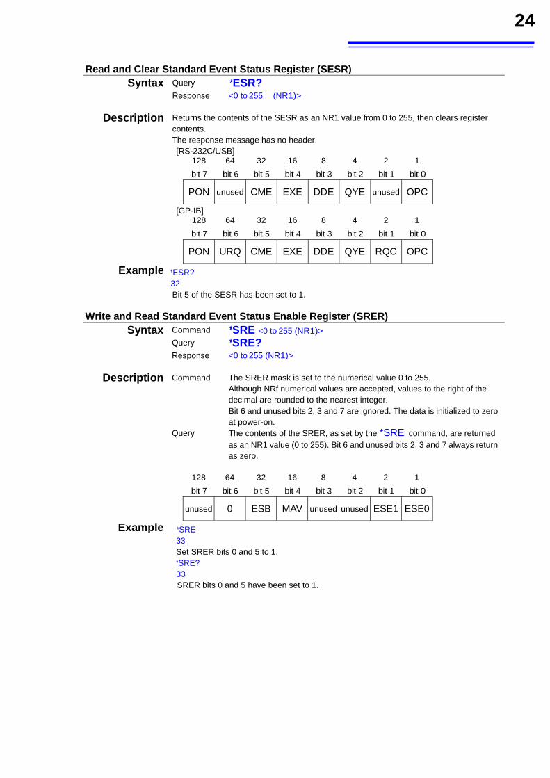
Read and Clear Standard Event Status Register (SESR) Syntax Query *ESR?
Response <0 to 255 (NR1)>
Description Returns the contents of the SESR as an NR1 value from 0 to 255, then clears register contents. The response message has no header. [RS-232C/USB]
128 64 32 16 8 4 2 1 bit 7 bit 6 bit 5 bit 4 bit 3 bit 2 bit 1 bit 0
PON unused CME EXE DDE QYE unused OPC
[GP-IB] 128 64 32 16 8 4 2 1 bit 7 bit 6 bit 5 bit 4 bit 3 bit 2 bit 1 bit 0
PON URQ CME EXE DDE QYE RQC OPC
Example *ESR? 32 Bit 5 of the SESR has been set to 1.
Write and Read Standard Event Status Enable Register (SRER) Syntax Command *SRE <0 to 255 (NR1)>
Query *SRE? Response <0 to 255 (NR1)>
Description Command The SRER mask is set to the numerical value 0 to 255. Although NRf numerical values are accepted, values to the right of the decimal are rounded to the nearest integer. Bit 6 and unused bits 2, 3 and 7 are ignored. The data is initialized to zero at power-on.
Query The contents of the SRER, as set by the *SRE command, are returned as an NR1 value (0 to 255). Bit 6 and unused bits 2, 3 and 7 always return as zero.
128 64 32 16 8 4 2 1 bit 7 bit 6 bit 5 bit 4 bit 3 bit 2 bit 1 bit 0
unused 0 ESB MAV unused unused ESE1 ESE0
Example *SRE
33
Set SRER bits 0 and 5 to 1. *SRE?
33 SRER bits 0 and 5 have been set to 1.
25
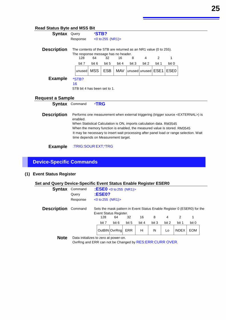
Read Status Byte and MSS Bit Syntax Query *STB?
Response <0 to 255 (NR1)>
Description The contents of the STB are returned as an NR1 value (0 to 255).
The response message has no header. 128 64 32 16 8 4 2 1 bit 7 bit 6 bit 5 bit 4 bit 3 bit 2 bit 1 bit 0
unused MSS ESB MAV unused unused ESE1 ESE0
Example *STB? 16 STB bit 4 has been set to 1.
Request a Sample Syntax Command *TRG
Description Performs one measurement when external triggering (trigger source <EXTERNAL>) is enabled. When Statistical Calculation is ON, imports calculation data. RM3545 When the memory function is enabled, the measured value is stored. RM3545 It may be necessary to insert wait processing after panel load or range selection. Wait time depends on Measurement target.
Example :TRIG:SOUR EXT;*TRG
Device-Specific Commands (1) Event Status Register
Set and Query Device-Specific Event Status Enable Register ESER0 Syntax Command :ESE0 <0 to 255 (NR1)>
Query :ESE0?
Response <0 to 255 (NR1)>
Description Command Sets the mask pattern in Event Status Enable Register 0 (ESER0) for the Event Status Register.
128 64 32 16 8 4 2 1 bit 7 bit 6 bit 5 bit 4 bit 3 bit 2 bit 1 bit 0
OutBIN OvrRng ERR Hi IN Lo INDEX EOM
Note Data initializes to zero at power-on. OvrRng and ERR can not be Changed by RES:ERR:CURR OVER.
26
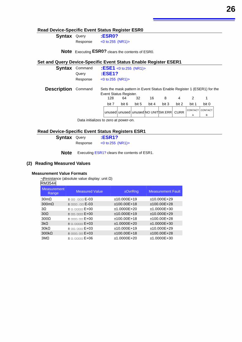
Read Device-Specific Event Status Register ESR0 Syntax Query :ESR0?
Response <0 to 255 (NR1)>
Note Executing ESR0? clears the contents of ESR0.
Set and Query Device-Specific Event Status Enable Register ESER1 Syntax Command :ESE1 <0 to 255 (NR1)>
Query :ESE1?
Response <0 to 255 (NR1)>
Description Command Sets the mask pattern in Event Status Enable Register 1 (ESER1) for the Event Status Register.
128 64 32 16 8 4 2 1 bit 7 bit 6 bit 5 bit 4 bit 3 bit 2 bit 1 bit 0
unused unused unused NO UNITSW.ERR CURR CONTACT
A
CONTACT
B
Data initializes to zero at power-on.
Read Device-Specific Event Status Registers ESR1 Syntax Query :ESR1?
Response <0 to 255 (NR1)>
Note Executing ESR1? clears the contents of ESR1.
(2) Reading Measured Values
Measurement Value Formats ・ Resistance (absolute value display: unit Ω) RM3544 Measurement
Range Measured Value ±OvrRng Measurement Fault
30mΩ ± . E-03 ±10.000E+19 ±10.000E+29 300mΩ ± . E-03 ±100.00E+18 ±100.00E+28 3Ω ± . E+00 ±1.0000E+20 ±1.0000E+30 30Ω ± . E+00 ±10.000E+19 ±10.000E+29 300Ω ± . E+00 ±100.00E+18 ±100.00E+28 3kΩ ± . E+03 ±1.0000E+20 ±1.0000E+30 30kΩ ± . E+03 ±10.000E+19 ±10.000E+29 300kΩ ± . E+03 ±100.00E+18 ±100.00E+28 3MΩ ± . E+06 ±1.0000E+20 ±1.0000E+30
27
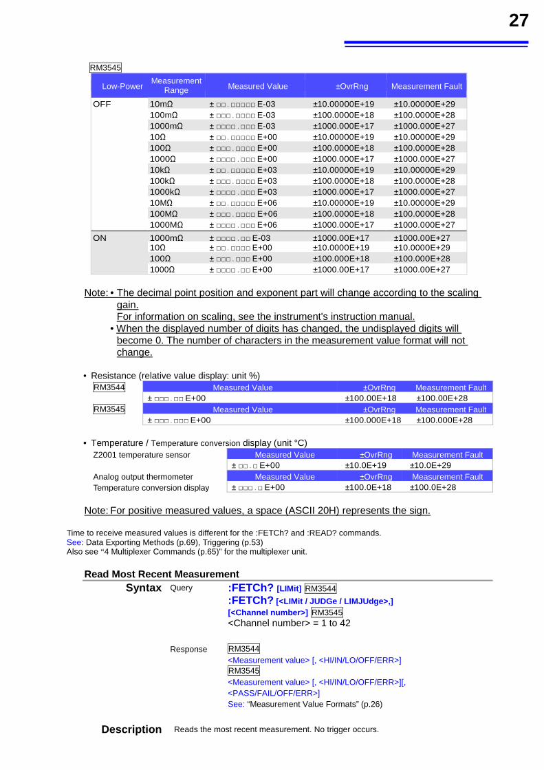
RM3545
Low-Power Measurement
Range Measured Value ±OvrRng Measurement Fault
OFF 10mΩ ± . E-03 ±10.00000E+19 ±10.00000E+29 100mΩ ± . E-03 ±100.0000E+18 ±100.0000E+28 1000mΩ ± . E-03 ±1000.000E+17 ±1000.000E+27 10Ω ± . E+00 ±10.00000E+19 ±10.00000E+29 100Ω ± . E+00 ±100.0000E+18 ±100.0000E+28 1000Ω ± . E+00 ±1000.000E+17 ±1000.000E+27 10kΩ ± . E+03 ±10.00000E+19 ±10.00000E+29 100kΩ ± . E+03 ±100.0000E+18 ±100.0000E+28 1000kΩ ± . E+03 ±1000.000E+17 ±1000.000E+27 10MΩ ± . E+06 ±10.00000E+19 ±10.00000E+29 100MΩ ± . E+06 ±100.0000E+18 ±100.0000E+28 1000MΩ ± . E+06 ±1000.000E+17 ±1000.000E+27
ON 1000mΩ ± . E-03 ±1000.00E+17 ±1000.00E+27 10Ω ± . E+00 ±10.0000E+19 ±10.0000E+29 100Ω ± . E+00 ±100.000E+18 ±100.000E+28 1000Ω ± . E+00 ±1000.00E+17 ±1000.00E+27
Note: • The decimal point position and exponent part will change according to the scaling gain.
For information on scaling, see the instrument's instruction manual. • When the displayed number of digits has changed, the undisplayed digits will
become 0. The number of characters in the measurement value format will not change.
• Resistance (relative value display: unit %) RM3544 Measured Value ±OvrRng Measurement Fault
± . E+00 ±100.00E+18 ±100.00E+28RM3545 Measured Value ±OvrRng Measurement Fault
± . E+00 ±100.000E+18 ±100.000E+28
• Temperature / Temperature conversion display (unit °C) Z2001 temperature sensor Measured Value ±OvrRng Measurement Fault
± . E+00 ±10.0E+19 ±10.0E+29 Analog output thermometer Temperature conversion display
Measured Value ±OvrRng Measurement Fault± . E+00 ±100.0E+18 ±100.0E+28
Note: For positive measured values, a space (ASCII 20H) represents the sign.
Time to receive measured values is different for the :FETCh? and :READ? commands. See: Data Exporting Methods (p.69), Triggering (p.53) Also see “4 Multiplexer Commands (p.65)” for the multiplexer unit.
Read Most Recent Measurement Syntax Query :FETCh? [LIMit] RM3544
:FETCh? [<LIMit / JUDGe / LIMJUdge>,] [<Channel number>] RM3545 <Channel number> = 1 to 42
Response RM3544 <Measurement value> [, <HI/IN/LO/OFF/ERR>] RM3545 <Measurement value> [, <HI/IN/LO/OFF/ERR>][, <PASS/FAIL/OFF/ERR>] See: “Measurement Value Formats” (p.26)
Description Reads the most recent measurement. No trigger occurs.
28
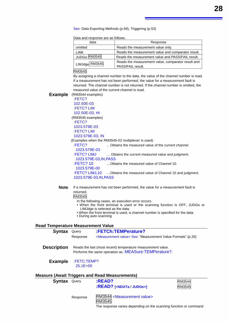
See: Data Exporting Methods (p.69), Triggering (p.53) Data and response are as follows.
data Response
omitted Reads the measurement value only.
LIMit Reads the measurement value and comparator result.JUDGe RM3545 Reads the measurement value and PASS/FAIL result.
LIMJdge RM3545 Reads the measurement value, comparator result and PASS/FAIL result.
RM3545 By assigning a channel number to the data, the value of the channel number is read. If a measurement has not been performed, the value for a measurement fault is returned. The channel number is not returned. If the channel number is omitted, the measured value of the current channel is read.
Example (RM3544 examples) :FETC? 102.50E-03 :FETC? LIM 102.50E-03, HI
(RM3545 examples) :FETC? 1023.579E-03 :FETC? LIM 1023.579E-03, IN
(Examples when the RM3545-02 multiplexer is used) :FETC? ... Obtains the measured value of the current channel. 1023.579E-03
:FETC? LIMJ … Obtains the current measured value and judgment. 1023.579E-03,IN,PASS
:FETC? 10 …Obtains the measured value of Channel 10. 1023.579E-00
:FETC? LIMJ,10 …Obtains the measured value of Channel 10 and judgment. 1023.579E-03,IN,PASS
Note If a measurement has not been performed, the value for a measurement fault is returned. RM3545
In the following cases, an execution error occurs. • When the front terminal is used or the scanning function is OFF, JUDGe or
LIMJdge is selected as the data. • When the front terminal is used, a channel number is specified for the data. • During auto scanning
Read Temperature Measurement Value Syntax Query :FETCh:TEMPerature?
Response <Measurement value> See: “Measurement Value Formats” (p.26)
Description Reads the last (most recent) temperature measurement value.
Performs the same operation as :MEASure:TEMPerature?.
Example :FETC:TEMP? 25.1E+00
Measure (Await Triggers and Read Measurements) Syntax Query :READ? RM3544
:READ? [<NDATa / JUDGe>] RM3545
Response RM3544 <Measurement value> RM3545 The response varies depending on the scanning function or command
29
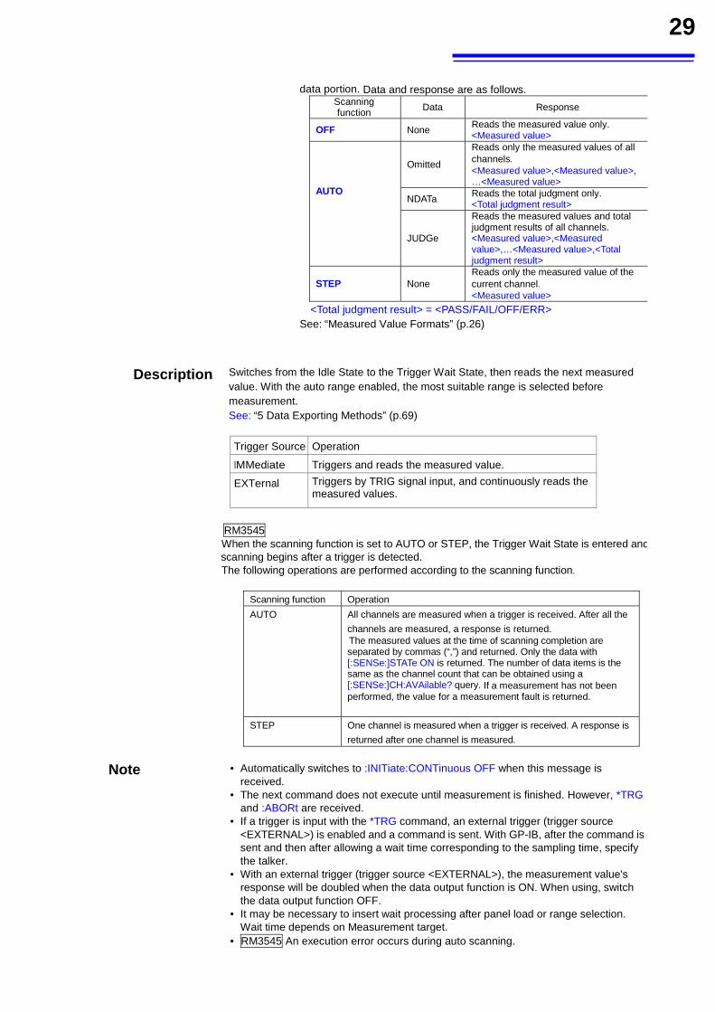
data portion. Data and response are as follows.
Scanning function Data Response
OFF None Reads the measured value only. <Measured value>
AUTO
Omitted Reads only the measured values of all channels.
<Measured value>,<Measured value>, …<Measured value>
NDATa Reads the total judgment only. <Total judgment result>
JUDGe Reads the measured values and total judgment results of all channels. <Measured value>,<Measured value>,…<Measured value>,<Total judgment result>
STEP None Reads only the measured value of the current channel. <Measured value>
<Total judgment result> = <PASS/FAIL/OFF/ERR>
See: “Measured Value Formats” (p.26)
Description Switches from the Idle State to the Trigger Wait State, then reads the next measured value. With the auto range enabled, the most suitable range is selected before measurement. See: “5 Data Exporting Methods” (p.69)
Trigger Source Operation
IMMediate Triggers and reads the measured value.
EXTernal Triggers by TRIG signal input, and continuously reads the measured values.
RM3545 When the scanning function is set to AUTO or STEP, the Trigger Wait State is entered and scanning begins after a trigger is detected. The following operations are performed according to the scanning function.
Scanning function Operation
AUTO All channels are measured when a trigger is received. After all the
channels are measured, a response is returned. The measured values at the time of scanning completion are separated by commas (“,”) and returned. Only the data with [:SENSe:]STATe ON is returned. The number of data items is the same as the channel count that can be obtained using a [:SENSe:]CH:AVAilable? query. If a measurement has not been performed, the value for a measurement fault is returned.
STEP One channel is measured when a trigger is received. A response is
returned after one channel is measured.
Note • Automatically switches to :INITiate:CONTinuous OFF when this message is received.
• The next command does not execute until measurement is finished. However, *TRG and :ABORt are received.
• If a trigger is input with the *TRG command, an external trigger (trigger source <EXTERNAL>) is enabled and a command is sent. With GP-IB, after the command is sent and then after allowing a wait time corresponding to the sampling time, specify the talker.
• With an external trigger (trigger source <EXTERNAL>), the measurement value's response will be doubled when the data output function is ON. When using, switch the data output function OFF.
• It may be necessary to insert wait processing after panel load or range selection. Wait time depends on Measurement target.
• RM3545 An execution error occurs during auto scanning.
30
Preset to Value Appropriate for Expected Measurement Value, and Measure Resistance RM3545
Syntax Query :MEASure:RESistance? <Expected measurement value> <Expected measurement value> = 0 to 1200E+06
Response <Measurement value> See: “Measurement Value Formats” (p.26)
Description When expected measurement values are input, the instrument will be set to an
optimum range that enables provided numerical data to be measured. When omitted, it enters the auto range. The MEASURE command operates as follows: 1. Disables continuous measurement of the trigger system. 2. Enables the internal trigger (trigger source <IMMEDIATE>). 3. Switches Low-Power Resistance measurement to OFF. 4. Moves to the specified range. 5. Executes one-time trigger. 6. Reads the measurement value. The MEASURE command executes the following commands internally: RES:LP:STAT OFF RES:RANG <Expected measurement value> (If the <Expected measurement value> is not present, then :RANG:AUTO ON) :INIT:CONT OFF
:TRIG:SOUR IMM
:READ?
Example :MEAS:RES?
150.1124E+03
Note • When the scaling function is being used, set the <expected value> to the value that existed prior to scaling (value in the range being used).
• If a transformer, coil, or other sample is inductive, measurement data may be returned before values have stabilized in auto range. In this case, either specify the range and measure, or utilize the delay function.
•An execution error occurs when the auto range is turned ON if the comparator function and BIN measurement function are ON.
• When the scanning function is set to STEP or AUTO, an execution error occurs. Preset to Value Appropriate for Expected Measurement Value, and Measure Low-Power Resistance
Syntax Query :MEASure:RESistance:LP? <Expected measurement value> <Expected measurement value> = 0 to1200E+03
Response <Measurement value> See: “Measurement Value Formats” (p.26)
Description When expected measurement values are input, the instrument will be set to an
optimum range that enables provided numerical data to be measured. When omitted, it enters the auto range.
The MEASURE command operates as follows: 1. Disables continuous measurement of the trigger system. 2. Enables internal trigger (trigger source <IMMEDIATE>). 3. Switches Low-Power Resistance measurement to ON. 4. Moves to the specified range. 5. Executes one-time trigger. 6. Reads the measurement value.
The MEASURE command executes the following commands internally: RES:LP:STAT ON
31
RES:LP:RANG <Expected measurement value> (If the <Expected measurement value> is not present, then :RANG:LP:AUTO ON) :INIT:CONT OFF
:TRIG:SOUR IMM
:READ?
Example :MEAS:RES:LP?
104.140E+00
Note • When the scaling function is being used, set the <expected value> to the value that existed prior to scaling (value in the range being used).
• If a transformer, coil, or other sample is inductive, measurement data may be returned before values have stabilized in auto range. At such time, either specify the range and measure, or utilize the delay function.
•An execution error occurs when the auto range is turned ON if the comparator function and BIN measurement function are ON.
• When the scanning function is set to STEP or AUTO, an execution error occurs. Read Temperature Measurement Value
Syntax Query :MEASure:TEMPerature? Response <Measurement value> See: “Measurement Value Formats” (p.26)
Description Reads the last (most recent) temperature measurement value.
Performs the same operation as :FETCh:TEMPerature?.
Example :MEAS:TEMP? 25.1E+00
Abort Measurement
Syntax Query :ABORt
Description Executes :READ /Scan measurement/Scan zero adjustment is abort (forced ermination).
Example :READ? :ABOR Executes an abort.
Note An abort cannot be executed as the instrument waits until all prior commands finish if the query is sent after a WAI command.
(3) Zero Adjustment
RM3545 An execution error occurs during scanning.
Execute Zero Adjustment Syntax Query :ADJust?
Response <0/1>
0 = Indicates zero adjustment succeeded. 1 = Indicates that zero adjustment has failed. For information on zero adjustment, see
the instrument instruction manual. Description RM3545
Executes scan zero adjustment (performs zero adjustment for the channels with :ADJust:ENABle ON) if the scanning function of the multiplexer is set to STEP or AUTO. Zero adjustment is performed only for the current channel if the scanning function is OFF. Scan zero adjustment can be aborted using :ABORt.
32
Clear Zero Adjustment Syntax Command :ADJust:CLEar
Description Clears any zero-adjustment offset.
Example ADJ:CLE
Note RM3545 When the multiplexer is used, zero adjustment for the current channel is canceled.
Query Zero Adjustment Execution State RM3545Syntax Query :ADJust:STATe?
Response <ON/OFF>
Example CH 10 :ADJ:STAT? ON
Set and Query Scan Zero Adjustment Execution RM3545 Syntax Command :ADJust:ENABle <1/0/ON/OFF>
Query :ADJust:ENABle?Response <ON/OFF>
Example CH 10 :ADJ:ENAB ON :ADJ:ENAB? ON
(4) Measurement Speed
RM3545 An execution error occurs during scanning.
Set and Query Measurement Speed
Syntax Command :SAMPle:RATE <Measurement speed>
RM3544 <Measurement speed>=FAST/MEDium/SLOW SLOW1/SLOW2 are handled the same as with SLOW.
RM3545 <Measurement speed>=FAST/MEDium/SLOW1 /SLOW2 SLOW is handled the same as with SLOW2.
Query :SAMPle:RATE? Response RM3544 <Measurement speed>=FAST/MEDium/SLOW
RM3545 <Measurement speed>=FAST/MEDium/SLOW1 /SLOW2
Example :SAMP:RATE MED :SAMP:RATE? MEDIUM
33
(5) Averaging Function
RM3545 An execution error occurs during scanning.
Execute and Query Averaging Function Syntax Command :CALCulate:AVERage:STATe <1/0/ON/OFF>
Query :CALCulate:AVERage:STATe?
Response <ON/OFF>
Example :CALC:AVER:STAT ON :CALC:AVER:STAT? ON
Set and Query Average Count Syntax Command :CALCulate:AVERage:COUNt < Count >
Query :CALCulate:AVERage:COUNt?
Response < Count >
< Count > = 2 ~ 100 (NR1)
Example :CALC:AVER:COUN 10 :CALC:AVER:COUN? 10
(6) Comparator
• When making comparator settings by commands, the measurement range is not automatically selected.
Execute and Query Comparator Syntax Command :CALCulate:LIMit:STATe <1/0/ON/OFF>
Query :CALCulate:LIMit:STATe?
Response <ON/OFF>
Example :CALC:LIM:STAT ON :CALC:LIM:STAT? ON
Note When the comparator is executed, the auto range , the temperature conversion function and BIN function enter the OFF state. RM3545 An execution error occurs during scanning.
Set and Query Beeper Syntax Command :CALCulate:LIMit:BEEPer <Condition>,<Type>,<Count>
Query :CALCulate:LIMit:BEEPer? <Condition>
Response <Condition>,<Type>,<Count>
<Condition> = RM3544 HI/ IN /LO RM3545 HI/ IN /LO /PASS/ FAIL <Type> = 0: Buzzer OFF, 1 to 3: Type 1 to 3 <Count> = 0: Continuous, 1 to 5: Count [times]
Example :CALC:LIM:BEEP IN,1,0 :CALC:LIM:BEEP? IN IN,1,0
Note RM3545 An execution error occurs during scanning.
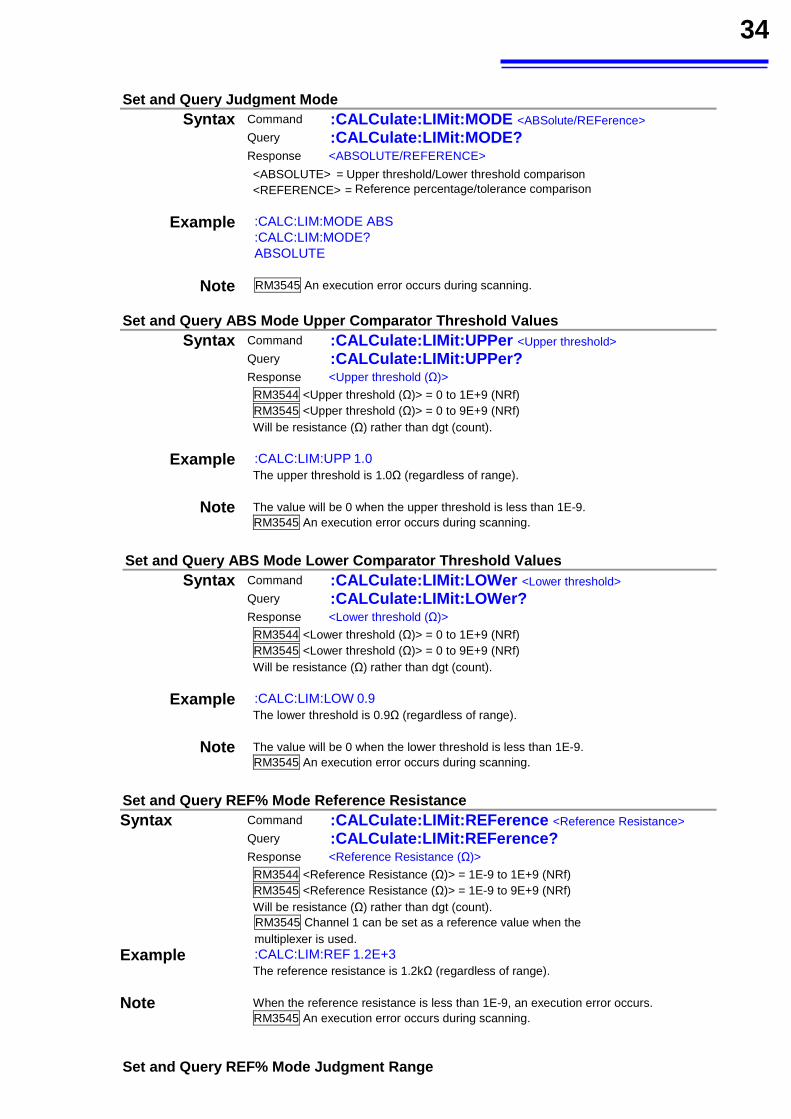
34
Set and Query Judgment Mode Syntax Command :CALCulate:LIMit:MODE <ABSolute/REFerence>
Query :CALCulate:LIMit:MODE?
Response <ABSOLUTE/REFERENCE>
<ABSOLUTE> = Upper threshold/Lower threshold comparison <REFERENCE> = Reference percentage/tolerance comparison
Example :CALC:LIM:MODE ABS :CALC:LIM:MODE? ABSOLUTE
Note RM3545 An execution error occurs during scanning.
Set and Query ABS Mode Upper Comparator Threshold Values Syntax Command :CALCulate:LIMit:UPPer <Upper threshold>
Query :CALCulate:LIMit:UPPer?
Response <Upper threshold (Ω)>
RM3544 <Upper threshold (Ω)> = 0 to 1E+9 (NRf) RM3545 <Upper threshold (Ω)> = 0 to 9E+9 (NRf) Will be resistance (Ω) rather than dgt (count).
Example :CALC:LIM:UPP 1.0 The upper threshold is 1.0Ω (regardless of range).
Note The value will be 0 when the upper threshold is less than 1E-9. RM3545 An execution error occurs during scanning.
Set and Query ABS Mode Lower Comparator Threshold Values
Syntax Command :CALCulate:LIMit:LOWer <Lower threshold> Query :CALCulate:LIMit:LOWer?
Response <Lower threshold (Ω)>
RM3544 <Lower threshold (Ω)> = 0 to 1E+9 (NRf) RM3545 <Lower threshold (Ω)> = 0 to 9E+9 (NRf) Will be resistance (Ω) rather than dgt (count).
Example :CALC:LIM:LOW 0.9 The lower threshold is 0.9Ω (regardless of range).
Note The value will be 0 when the lower threshold is less than 1E-9. RM3545 An execution error occurs during scanning.
Set and Query REF% Mode Reference Resistance Syntax Command :CALCulate:LIMit:REFerence <Reference Resistance>
Query :CALCulate:LIMit:REFerence?
Response <Reference Resistance (Ω)>
RM3544 <Reference Resistance (Ω)> = 1E-9 to 1E+9 (NRf) RM3545 <Reference Resistance (Ω)> = 1E-9 to 9E+9 (NRf) Will be resistance (Ω) rather than dgt (count). RM3545 Channel 1 can be set as a reference value when the multiplexer is used.
Example :CALC:LIM:REF 1.2E+3 The reference resistance is 1.2kΩ (regardless of range).
Note When the reference resistance is less than 1E-9, an execution error occurs. RM3545 An execution error occurs during scanning.
Set and Query REF% Mode Judgment Range
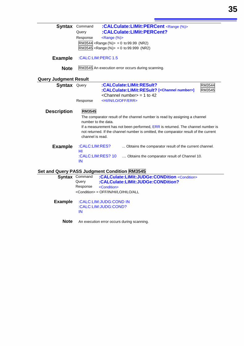
35
Syntax Command :CALCulate:LIMit:PERCent <Range (%)> Query :CALCulate:LIMit:PERCent?
Response <Range (%)>
RM3544 <Range (%)> = 0 to 99.99 (NR2) RM3545 <Range (%)> = 0 to 99.999 (NR2)
Example :CALC:LIM:PERC 1.5
Note RM3545 An execution error occurs during scanning.
Query Judgment Result Syntax Query :CALCulate:LIMit:RESult? RM3544
:CALCulate:LIMit:RESult? [<Channel number>] RM3545
<Channel number> = 1 to 42 Response <HI/IN/LO/OFF/ERR>
Description RM3545
The comparator result of the channel number is read by assigning a channel number to the data. If a measurement has not been performed, ERR is returned. The channel number is not returned. If the channel number is omitted, the comparator result of the current channel is read.
Example :CALC:LIM:RES? ... Obtains the comparator result of the current channel. HI :CALC:LIM:RES? 10 … Obtains the comparator result of Channel 10. IN
Set and Query PASS Judgment Condition RM3545
Syntax Command :CALCulate:LIMit:JUDGe:CONDition <Condition> Query :CALCulate:LIMit:JUDGe:CONDition? Response <Condition><Condition> = OFF/IN/HI/LO/HILO/ALL
Example :CALC:LIM:JUDG:COND IN
:CALC:LIM:JUDG:COND? IN
Note An execution error occurs during scanning.
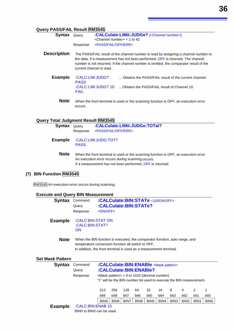
36
Query PASS/FAIL Result RM3545
Syntax Query :CALCulate:LIMit:JUDGe? [<Channel number>] <Channel number> = 1 to 42
Response <PASS/FAIL/OFF/ERR>
Description The PASS/FAIL result of the channel number is read by assigning a channel number to
the data. If a measurement has not been performed, OFF is returned. The channel number is not returned. If the channel number is omitted, the comparator result of the current channel is read.
Example :CALC:LIM:JUDG? ... Obtains the PASS/FAIL result of the current channel.
PASS :CALC:LIM:JUDG? 10 …Obtains the PASS/FAIL result of Channel 10.
FAIL
Note When the front terminal is used or the scanning function is OFF, an execution error occurs.
Query Total Judgment Result RM3545Syntax Query :CALCulate:LIMit:JUDGe:TOTal?
Response <PASS/FAIL/OFF/ERR>
Example :CALC:LIM:JUDG:TOT?
PASS
Note When the front terminal is used or the scanning function is OFF, an execution error An execution error occurs during scanning.occurs. If a measurement has not been performed, OFF is returned.
(7) BIN Function RM3545
RM3545 An execution error occurs during scanning.
Execute and Query BIN Measurement Syntax Command :CALCulate:BIN:STATe <1/0/ON/OFF>
Query :CALCulate:BIN:STATe?
Response <ON/OFF>
Example :CALC:BIN:STAT ON :CALC:BIN:STAT? ON
Note When the BIN function is executed, the comparator function, auto range, and temperature conversion function all switch to OFF. In addition, the front terminal is used as a measurement terminal.
Set Mask Pattern
Syntax Command :CALCulate:BIN:ENABle <Mask pattern> Query :CALCulate:BIN:ENABle?
Response <Mask pattern> = 0 to 1023 (decimal number) “1” will be the BIN number bit used to execute the BIN measurement.
512 256 128 64 32 16 8 4 2 1
bit9 bit8 bit7 bit6 bit5 bit4 bit3 bit2 bit1 bit0
BIN9 BIN8 BIN7 BIN6 BIN5 BIN4 BIN3 BIN2 BIN1 BIN0
Example :CALC:BIN:ENAB 15 BIN0 to BIN3 can be used.
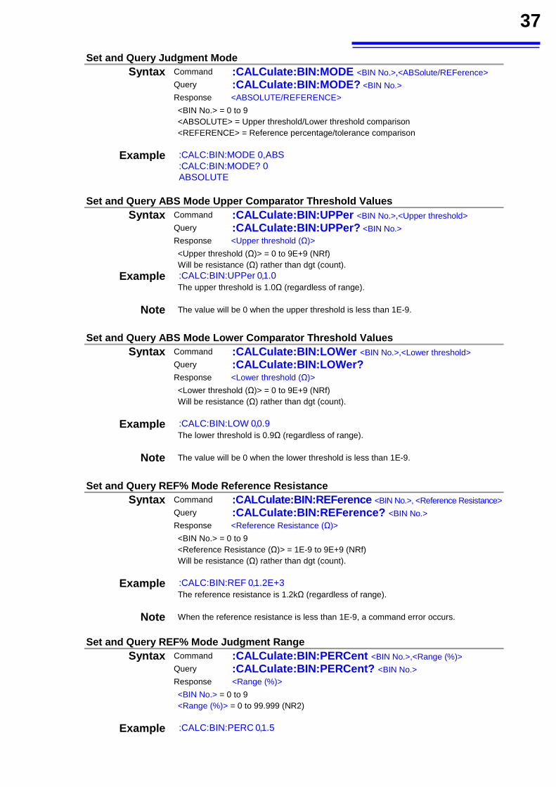
37
Set and Query Judgment Mode Syntax Command :CALCulate:BIN:MODE <BIN No.>,<ABSolute/REFerence>
Query :CALCulate:BIN:MODE? <BIN No.>
Response <ABSOLUTE/REFERENCE>
<BIN No.> = 0 to 9 <ABSOLUTE> = Upper threshold/Lower threshold comparison <REFERENCE> = Reference percentage/tolerance comparison
Example :CALC:BIN:MODE 0,ABS :CALC:BIN:MODE? 0 ABSOLUTE
Set and Query ABS Mode Upper Comparator Threshold Values
Syntax Command :CALCulate:BIN:UPPer <BIN No.>,<Upper threshold> Query :CALCulate:BIN:UPPer? <BIN No.>
Response <Upper threshold (Ω)>
<Upper threshold (Ω)> = 0 to 9E+9 (NRf) Will be resistance (Ω) rather than dgt (count).
Example :CALC:BIN:UPPer 0,1.0 The upper threshold is 1.0Ω (regardless of range).
Note The value will be 0 when the upper threshold is less than 1E-9.
Set and Query ABS Mode Lower Comparator Threshold Values
Syntax Command :CALCulate:BIN:LOWer <BIN No.>,<Lower threshold> Query :CALCulate:BIN:LOWer?
Response <Lower threshold (Ω)>
<Lower threshold (Ω)> = 0 to 9E+9 (NRf) Will be resistance (Ω) rather than dgt (count).
Example :CALC:BIN:LOW 0,0.9 The lower threshold is 0.9Ω (regardless of range).
Note The value will be 0 when the lower threshold is less than 1E-9.
Set and Query REF% Mode Reference Resistance
Syntax Command :CALCulate:BIN:REFerence <BIN No.>, <Reference Resistance>Query :CALCulate:BIN:REFerence? <BIN No.>
Response <Reference Resistance (Ω)>
<BIN No.> = 0 to 9 <Reference Resistance (Ω)> = 1E-9 to 9E+9 (NRf) Will be resistance (Ω) rather than dgt (count).
Example :CALC:BIN:REF 0,1.2E+3 The reference resistance is 1.2kΩ (regardless of range).
Note When the reference resistance is less than 1E-9, a command error occurs.
Set and Query REF% Mode Judgment Range
Syntax Command :CALCulate:BIN:PERCent <BIN No.>,<Range (%)> Query :CALCulate:BIN:PERCent? <BIN No.>
Response <Range (%)>
<BIN No.> = 0 to 9 <Range (%)> = 0 to 99.999 (NR2)
Example :CALC:BIN:PERC 0,1.5
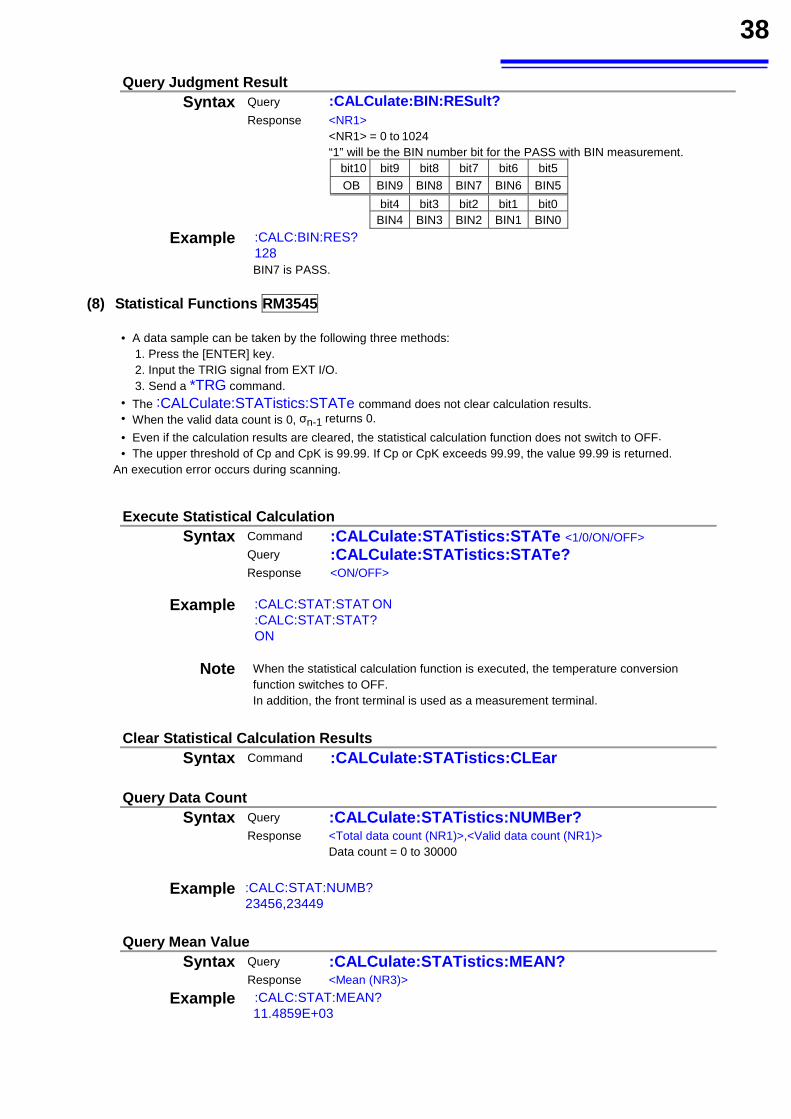
38
Query Judgment Result Syntax Query :CALCulate:BIN:RESult?
Response <NR1> <NR1> = 0 to 1024 “1” will be the BIN number bit for the PASS with BIN measurement.
bit10 bit9 bit8 bit7 bit6 bit5 OB BIN9 BIN8 BIN7 BIN6 BIN5 bit4 bit3 bit2 bit1 bit0 BIN4 BIN3 BIN2 BIN1 BIN0
Example :CALC:BIN:RES? 128 BIN7 is PASS.
(8) Statistical Functions RM3545
• A data sample can be taken by the following three methods: 1. Press the [ENTER] key. 2. Input the TRIG signal from EXT I/O. 3. Send a *TRG command.
• The :CALCulate:STATistics:STATe command does not clear calculation results. • When the valid data count is 0, σn-1 returns 0.
• Even if the calculation results are cleared, the statistical calculation function does not switch to OFF. • The upper threshold of Cp and CpK is 99.99. If Cp or CpK exceeds 99.99, the value 99.99 is returned.
An execution error occurs during scanning.
Execute Statistical Calculation Syntax Command :CALCulate:STATistics:STATe <1/0/ON/OFF>
Query :CALCulate:STATistics:STATe?
Response <ON/OFF>
Example :CALC:STAT:STAT ON :CALC:STAT:STAT? ON
Note When the statistical calculation function is executed, the temperature conversion function switches to OFF. In addition, the front terminal is used as a measurement terminal.
Clear Statistical Calculation Results
Syntax Command :CALCulate:STATistics:CLEar
Query Data Count Syntax Query :CALCulate:STATistics:NUMBer?
Response <Total data count (NR1)>,<Valid data count (NR1)> Data count = 0 to 30000
Example :CALC:STAT:NUMB?
23456,23449
Query Mean Value
Syntax Query :CALCulate:STATistics:MEAN? Response <Mean (NR3)>
Example :CALC:STAT:MEAN? 11.4859E+03
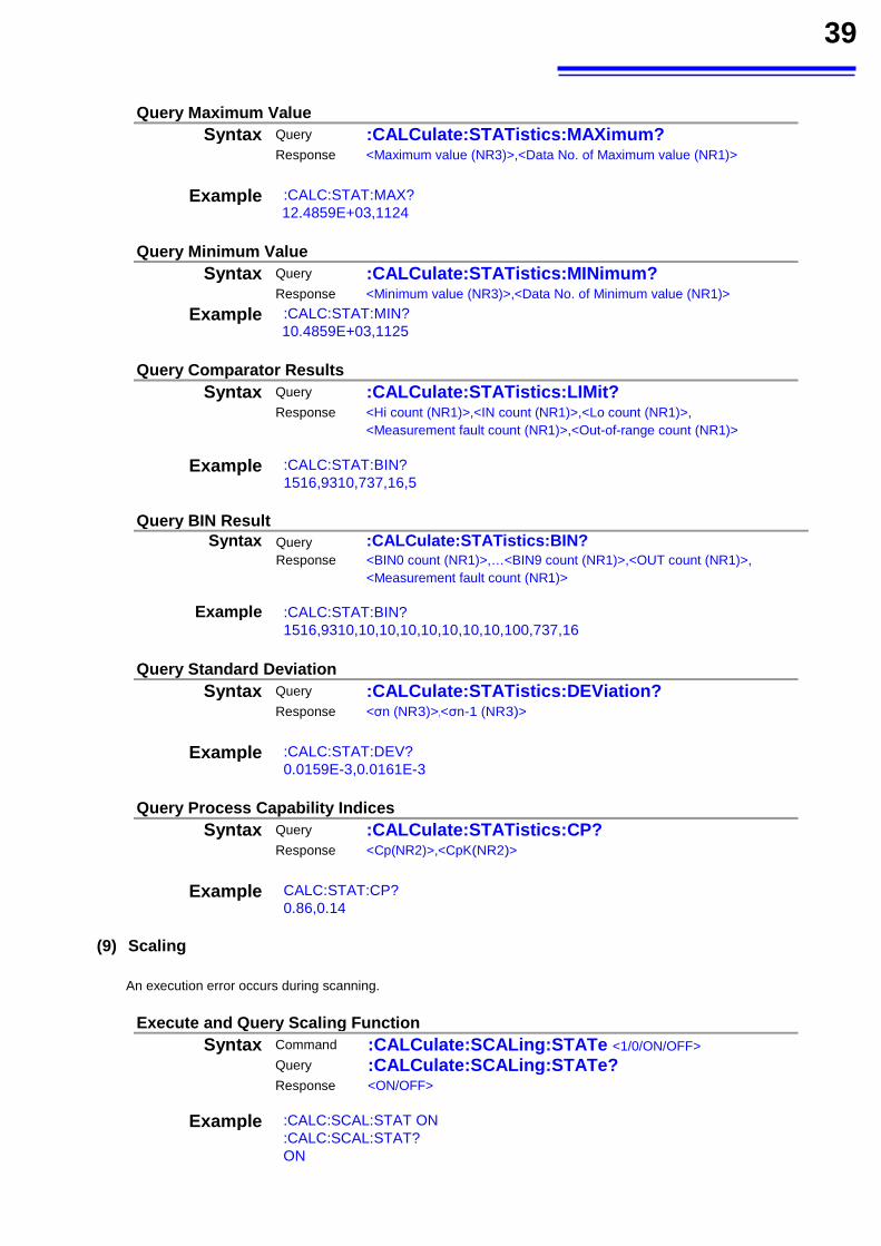
39
Query Maximum Value
Syntax Query :CALCulate:STATistics:MAXimum? Response <Maximum value (NR3)>,<Data No. of Maximum value (NR1)>
Example :CALC:STAT:MAX?
12.4859E+03,1124
Query Minimum Value Syntax Query :CALCulate:STATistics:MINimum?
Response <Minimum value (NR3)>,<Data No. of Minimum value (NR1)>
Example :CALC:STAT:MIN? 10.4859E+03,1125
Query Comparator Results
Syntax Query :CALCulate:STATistics:LIMit? Response <Hi count (NR1)>,<IN count (NR1)>,<Lo count (NR1)>,
<Measurement fault count (NR1)>,<Out-of-range count (NR1)>
Example :CALC:STAT:BIN? 1516,9310,737,16,5
Query BIN Result
Syntax Query :CALCulate:STATistics:BIN?Response <BIN0 count (NR1)>,…<BIN9 count (NR1)>,<OUT count (NR1)>,
<Measurement fault count (NR1)>
Example :CALC:STAT:BIN? 1516,9310,10,10,10,10,10,10,10,100,737,16
Query Standard Deviation
Syntax Query :CALCulate:STATistics:DEViation? Response <σn (NR3)>,<σn-1 (NR3)>
Example :CALC:STAT:DEV?
0.0159E-3,0.0161E-3
Query Process Capability Indices Syntax Query :CALCulate:STATistics:CP?
Response <Cp(NR2)>,<CpK(NR2)>
Example CALC:STAT:CP?
0.86,0.14 (9) Scaling
An execution error occurs during scanning.
Execute and Query Scaling Function Syntax Command :CALCulate:SCALing:STATe <1/0/ON/OFF>
Query :CALCulate:SCALing:STATe?
Response <ON/OFF>
Example :CALC:SCAL:STAT ON :CALC:SCAL:STAT? ON
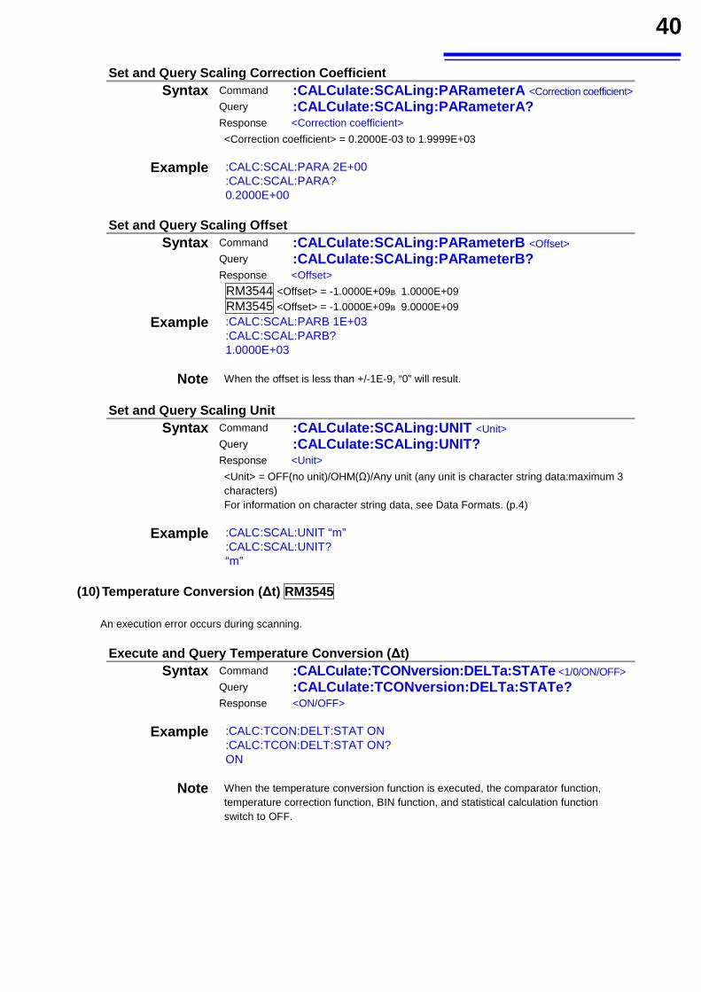
40
Set and Query Scaling Correction Coefficient Syntax Command :CALCulate:SCALing:PARameterA <Correction coefficient>
Query :CALCulate:SCALing:PARameterA?
Response <Correction coefficient>
<Correction coefficient> = 0.2000E-03 to 1.9999E+03
Example :CALC:SCAL:PARA 2E+00 :CALC:SCAL:PARA? 0.2000E+00
Set and Query Scaling Offset
Syntax Command :CALCulate:SCALing:PARameterB <Offset> Query :CALCulate:SCALing:PARameterB?
Response <Offset>
RM3544 <Offset> = -1.0000E+09~1.0000E+09
RM3545 <Offset> = -1.0000E+09~9.0000E+09
Example :CALC:SCAL:PARB 1E+03 :CALC:SCAL:PARB? 1.0000E+03
Note When the offset is less than +/-1E-9, “0” will result.
Set and Query Scaling Unit
Syntax Command :CALCulate:SCALing:UNIT <Unit> Query :CALCulate:SCALing:UNIT?
Response <Unit>
<Unit> = OFF(no unit)/OHM(Ω)/Any unit (any unit is character string data:maximum 3 characters) For information on character string data, see Data Formats. (p.4)
Example :CALC:SCAL:UNIT “m” :CALC:SCAL:UNIT? “m”
(10) Temperature Conversion (∆t) RM3545
An execution error occurs during scanning.
Execute and Query Temperature Conversion (∆t) Syntax Command :CALCulate:TCONversion:DELTa:STATe <1/0/ON/OFF>
Query :CALCulate:TCONversion:DELTa:STATe?
Response <ON/OFF>
Example :CALC:TCON:DELT:STAT ON :CALC:TCON:DELT:STAT ON? ON
Note When the temperature conversion function is executed, the comparator function, temperature correction function, BIN function, and statistical calculation function switch to OFF.
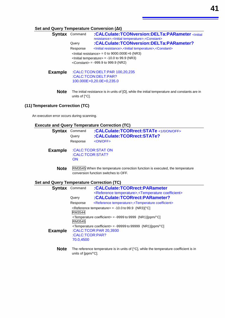
41
Set and Query Temperature Conversion (∆t)
Syntax Command :CALCulate:TCONversion:DELTa:PARameter <Initial resistance>,<Initial temperature>,<Constant>
Query :CALCulate:TCONversion:DELTa:PARameter?
Response <Initial resistance>,<Initial temperature>,<Constant>
<Initial resistance> = 0 to 9000.000E+6 (NR3) <Initial temperature> = -10.0 to 99.9 (NR3) <Constant> = -999.9 to 999.9 (NR2)
Example :CALC:TCON:DELT:PAR 100,20,235 :CALC:TCON:DELT:PAR? 100.000E+0,20.0E+0,235.0
Note The initial resistance is in units of [Ω], while the initial temperature and constants are in units of [°C].
(11) Temperature Correction (TC)
An execution error occurs during scanning.
Execute and Query Temperature Correction (TC) Syntax Command :CALCulate:TCORrect:STATe <1/0/ON/OFF>
Query :CALCulate:TCORrect:STATe?
Response <ON/OFF>
Example :CALC:TCOR:STAT ON :CALC:TCOR:STAT? ON
Note RM3545 When the temperature correction function is executed, the temperature conversion function switches to OFF.
Set and Query Temperature Correction (TC)
Syntax Command :CALCulate:TCORrect:PARameter <Reference temperature>,<Temperature coefficient>
Query :CALCulate:TCORrect:PARameter?
Response <Reference temperature>,<Temperature coefficient>
<Reference temperature> = -10.0 to 99.9 (NR3)[°C] RM3544 <Temperature coefficient> = -9999 to 9999 (NR1)[ppm/°C] RM3545 <Temperature coefficient> = -99999 to 99999 (NR1)[ppm/°C]
Example :CALC:TCOR:PAR 20,3930 :CALC:TCOR:PAR? 70.0,4500
Note The reference temperature is in units of [°C], while the temperature coefficient is in units of [ppm/°C].
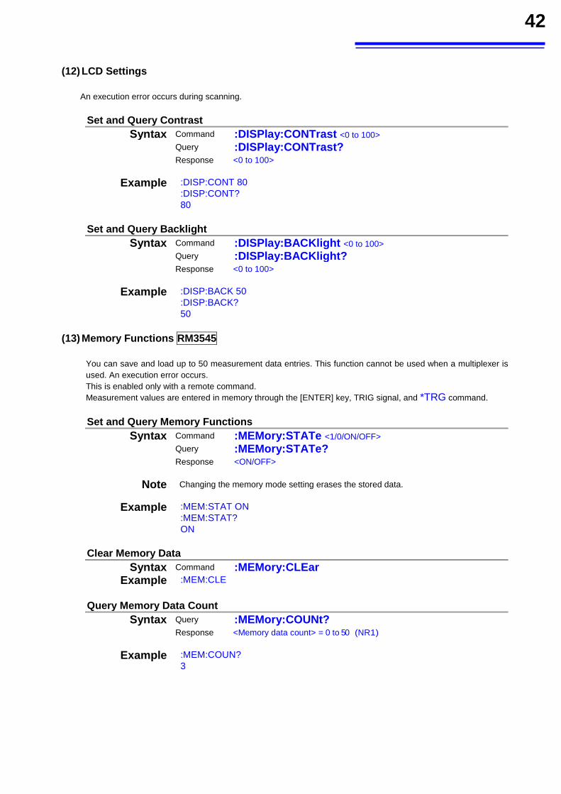
42
(12) LCD Settings
An execution error occurs during scanning.
Set and Query Contrast Syntax Command :DISPlay:CONTrast <0 to 100>
Query :DISPlay:CONTrast?
Response <0 to 100>
Example :DISP:CONT 80 :DISP:CONT? 80
Set and Query Backlight Syntax Command :DISPlay:BACKlight <0 to 100>
Query :DISPlay:BACKlight?
Response <0 to 100>
Example :DISP:BACK 50 :DISP:BACK? 50
(13) Memory Functions RM3545
You can save and load up to 50 measurement data entries. This function cannot be used when a multiplexer is used. An execution error occurs. This is enabled only with a remote command. Measurement values are entered in memory through the [ENTER] key, TRIG signal, and *TRG command.
Set and Query Memory Functions Syntax Command :MEMory:STATe <1/0/ON/OFF>
Query :MEMory:STATe?
Response <ON/OFF>
Note Changing the memory mode setting erases the stored data.
Example :MEM:STAT ON :MEM:STAT? ON
Clear Memory Data
Syntax Command :MEMory:CLEar Example :MEM:CLE
Query Memory Data Count Syntax Query :MEMory:COUNt?
Response <Memory data count> = 0 to 50 (NR1)
Example :MEM:COUN? 3
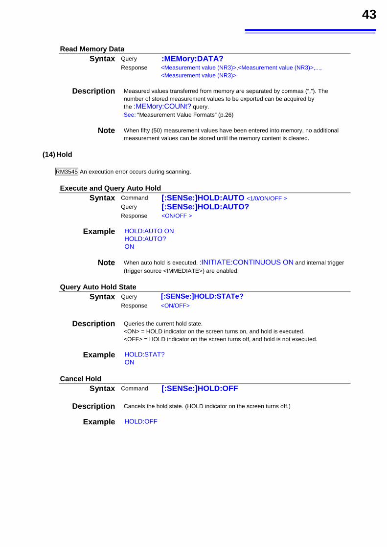
43
Read Memory Data
Syntax Query :MEMory:DATA?
Response <Measurement value (NR3)>,<Measurement value (NR3)>,..., <Measurement value (NR3)>
Description Measured values transferred from memory are separated by commas (“,”). The number of stored measurement values to be exported can be acquired by the :MEMory:COUNt? query. See: “Measurement Value Formats” (p.26)
Note When fifty (50) measurement values have been entered into memory, no additional measurement values can be stored until the memory content is cleared.
(14) Hold
RM3545 An execution error occurs during scanning.
Execute and Query Auto Hold Syntax Command [:SENSe:]HOLD:AUTO <1/0/ON/OFF >
Query [:SENSe:]HOLD:AUTO?
Response <ON/OFF >
Example HOLD:AUTO ON HOLD:AUTO? ON
Note When auto hold is executed, :INITIATE:CONTINUOUS ON and internal trigger (trigger source <IMMEDIATE>) are enabled.
Query Auto Hold State
Syntax Query [:SENSe:]HOLD:STATe?
Response <ON/OFF>
Description Queries the current hold state.
<ON> = HOLD indicator on the screen turns on, and hold is executed. <OFF> = HOLD indicator on the screen turns off, and hold is not executed.
Example HOLD:STAT? ON
Cancel Hold
Syntax Command [:SENSe:]HOLD:OFF
Description Cancels the hold state. (HOLD indicator on the screen turns off.)
Example HOLD:OFF
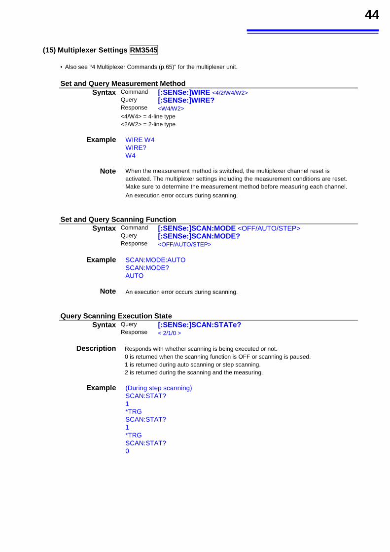
44
(15) Multiplexer Settings RM3545
• Also see “4 Multiplexer Commands (p.65)” for the multiplexer unit.
Set and Query Measurement Method
Syntax Command [:SENSe:]WIRE <4/2/W4/W2>Query [:SENSe:]WIRE?Response <W4/W2><4/W4> = 4-line type
<2/W2> = 2-line type
Example WIRE W4 WIRE? W4
Note When the measurement method is switched, the multiplexer channel reset is activated. The multiplexer settings including the measurement conditions are reset. Make sure to determine the measurement method before measuring each channel. An execution error occurs during scanning.
Set and Query Scanning Function
Syntax Command [:SENSe:]SCAN:MODE <OFF/AUTO/STEP> Query [:SENSe:]SCAN:MODE?Response <OFF/AUTO/STEP>
Example SCAN:MODE:AUTO SCAN:MODE? AUTO
Note An execution error occurs during scanning.
Query Scanning Execution State
Syntax Query [:SENSe:]SCAN:STATe?Response < 2/1/0 >
Description Responds with whether scanning is being executed or not. 0 is returned when the scanning function is OFF or scanning is paused. 1 is returned during auto scanning or step scanning. 2 is returned during the scanning and the measuring.
Example (During step scanning) SCAN:STAT? 1 *TRG SCAN:STAT? 1 *TRG SCAN:STAT? 0
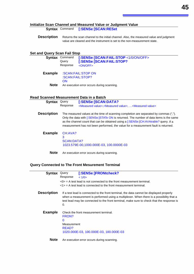
45
Initialize Scan Channel and Measured Value or Judgment Value
Syntax Command [:SENSe:]SCAN:RESet
Description Returns the scan channel to the initial channel. Also, the measured value and judgment value are cleared and the instrument is set to the non-measurement state.
Set and Query Scan Fail Stop
Syntax Command [:SENSe:]SCAN:FAIL:STOP <1/0/ON/OFF> Query [:SENSe:]SCAN:FAIL:STOP?Response <ON/OFF>
Example :SCAN:FAIL:STOP ON :SCAN:FAIL:STOP? ON
Note An execution error occurs during scanning.
Read Scanned Measurement Data in a Batch
Syntax Query [:SENSe:]SCAN:DATA?Response <Measured value>,<Measured value>, …<Measured value>
Description The measured values at the time of scanning completion are separated by commas (“,”). Only the data with [:SENSe:]STATe ON is returned. The number of data items is the same as the channel count that can be obtained using a [:SENSe:]CH:AVAirable? query. If a measurement has not been performed, the value for a measurement fault is returned.
Example CH:AVA? 3 SCAN:DATA? 1023.579E-00,1000.000E-03, 100.0000E-03
Note An execution error occurs during scanning.
Query Connected to The Front Mesurement Terminal
Syntax Query [:SENSe:]FRONtcheck?Response < 1/0> <0> = A test lead is not connected to the front measurement terminal. <1> = A test lead is connected to the front measurement terminal.
Description If a test lead is connected to the front terminal, the data cannot be displayed properly when a measurement is performed using a multiplexer. When there is a possibility that a test lead may be connected to the front terminal, make sure to check that the response is 0.
Example Check the front measurement terminal. FRON? 0 Measurement READ? 1020.000E-03, 100.000E-03, 100.000E-03
Note An execution error occurs during scanning.
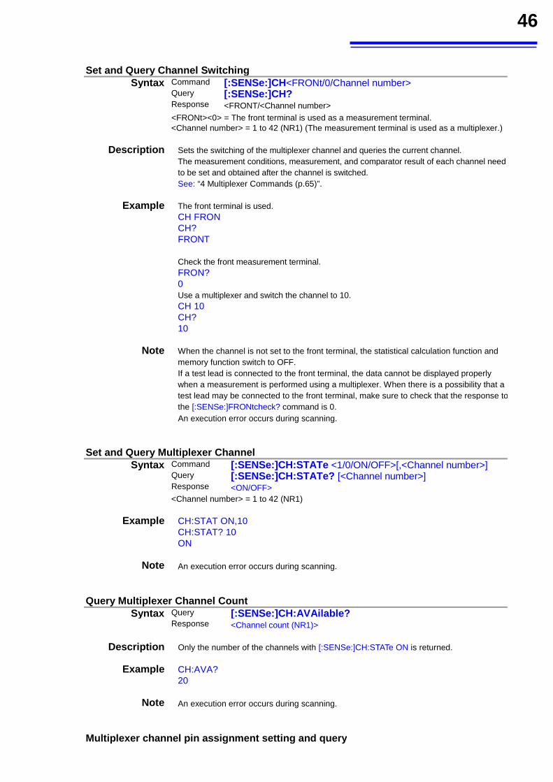
46
Set and Query Channel Switching
Syntax Command [:SENSe:]CH<FRONt/0/Channel number> Query [:SENSe:]CH?Response <FRONT/<Channel number><FRONt><0> = The front terminal is used as a measurement terminal. <Channel number> = 1 to 42 (NR1) (The measurement terminal is used as a multiplexer.)
Description Sets the switching of the multiplexer channel and queries the current channel. The measurement conditions, measurement, and comparator result of each channel need to be set and obtained after the channel is switched. See: “4 Multiplexer Commands (p.65)”.
Example The front terminal is used. CH FRON CH? FRONT
Check the front measurement terminal. FRON? 0
Use a multiplexer and switch the channel to 10. CH 10 CH? 10
Note When the channel is not set to the front terminal, the statistical calculation function and memory function switch to OFF. If a test lead is connected to the front terminal, the data cannot be displayed properly when a measurement is performed using a multiplexer. When there is a possibility that a test lead may be connected to the front terminal, make sure to check that the response to the [:SENSe:]FRONtcheck? command is 0. An execution error occurs during scanning.
Set and Query Multiplexer Channel
Syntax Command [:SENSe:]CH:STATe <1/0/ON/OFF>[,<Channel number>]Query [:SENSe:]CH:STATe? [<Channel number>] Response <ON/OFF><Channel number> = 1 to 42 (NR1)
Example CH:STAT ON,10 CH:STAT? 10 ON
Note An execution error occurs during scanning.
Query Multiplexer Channel Count
Syntax Query [:SENSe:]CH:AVAilable?Response <Channel count (NR1)>
Description Only the number of the channels with [:SENSe:]CH:STATe ON is returned.
Example CH:AVA? 20
Note An execution error occurs during scanning.
Multiplexer channel pin assignment setting and query
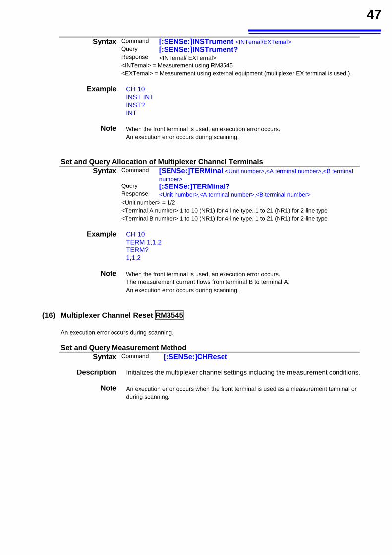
47
Syntax Command [:SENSe:]INSTrument <INTernal/EXTernal> Query [:SENSe:]INSTrument?Response <INTernal/ EXTernal><INTernal> = Measurement using RM3545
<EXTernal> = Measurement using external equipment (multiplexer EX terminal is used.)
Example CH 10 INST INT INST? INT
Note When the front terminal is used, an execution error occurs. An execution error occurs during scanning.
Set and Query Allocation of Multiplexer Channel Terminals
Syntax Command [SENSe:]TERMinal <Unit number>,<A terminal number>,<B terminal number>
Query [:SENSe:]TERMinal?Response <Unit number>,<A terminal number>,<B terminal number> <Unit number> = 1/2 <Terminal A number> 1 to 10 (NR1) for 4-line type, 1 to 21 (NR1) for 2-line type <Terminal B number> 1 to 10 (NR1) for 4-line type, 1 to 21 (NR1) for 2-line type
Example CH 10 TERM 1,1,2 TERM? 1,1,2
Note When the front terminal is used, an execution error occurs. The measurement current flows from terminal B to terminal A. An execution error occurs during scanning.
(16) Multiplexer Channel Reset RM3545
An execution error occurs during scanning.
Set and Query Measurement MethodSyntax Command [:SENSe:]CHReset
Description Initializes the multiplexer channel settings including the measurement conditions.
Note An execution error occurs when the front terminal is used as a measurement terminal or during scanning.
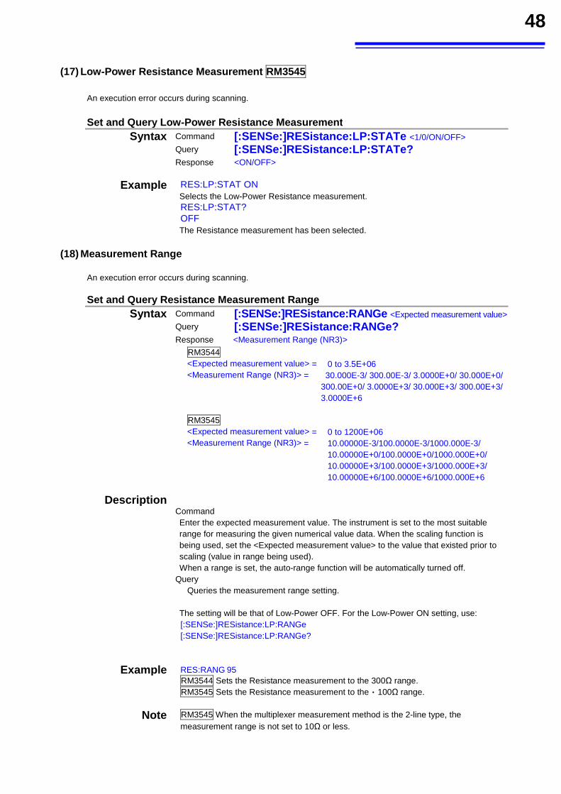
48
(17) Low-Power Resistance Measurement RM3545 An execution error occurs during scanning. Set and Query Low-Power Resistance Measurement
Syntax Command [:SENSe:]RESistance:LP:STATe <1/0/ON/OFF> Query [:SENSe:]RESistance:LP:STATe?
Response <ON/OFF>
Example RES:LP:STAT ON Selects the Low-Power Resistance measurement. RES:LP:STAT? OFF The Resistance measurement has been selected.
(18) Measurement Range
An execution error occurs during scanning.
Set and Query Resistance Measurement Range Syntax Command [:SENSe:]RESistance:RANGe <Expected measurement value>
Query [:SENSe:]RESistance:RANGe?
Response <Measurement Range (NR3)>
RM3544 <Expected measurement value> = 0 to 3.5E+06 <Measurement Range (NR3)> = 30.000E-3/ 300.00E-3/ 3.0000E+0/ 30.000E+0/
300.00E+0/ 3.0000E+3/ 30.000E+3/ 300.00E+3/3.0000E+6
RM3545 <Expected measurement value> = 0 to 1200E+06 <Measurement Range (NR3)> = 10.00000E-3/100.0000E-3/1000.000E-3/
10.00000E+0/100.0000E+0/1000.000E+0/ 10.00000E+3/100.0000E+3/1000.000E+3/ 10.00000E+6/100.0000E+6/1000.000E+6
Description
Command Enter the expected measurement value. The instrument is set to the most suitable range for measuring the given numerical value data. When the scaling function is being used, set the <Expected measurement value> to the value that existed prior to scaling (value in range being used). When a range is set, the auto-range function will be automatically turned off.
Query Queries the measurement range setting.
The setting will be that of Low-Power OFF. For the Low-Power ON setting, use: [:SENSe:]RESistance:LP:RANGe [:SENSe:]RESistance:LP:RANGe?
Example RES:RANG 95 RM3544 Sets the Resistance measurement to the 300Ω range. RM3545 Sets the Resistance measurement to the 100Ω range.
Note RM3545 When the multiplexer measurement method is the 2-line type, the measurement range is not set to 10Ω or less.
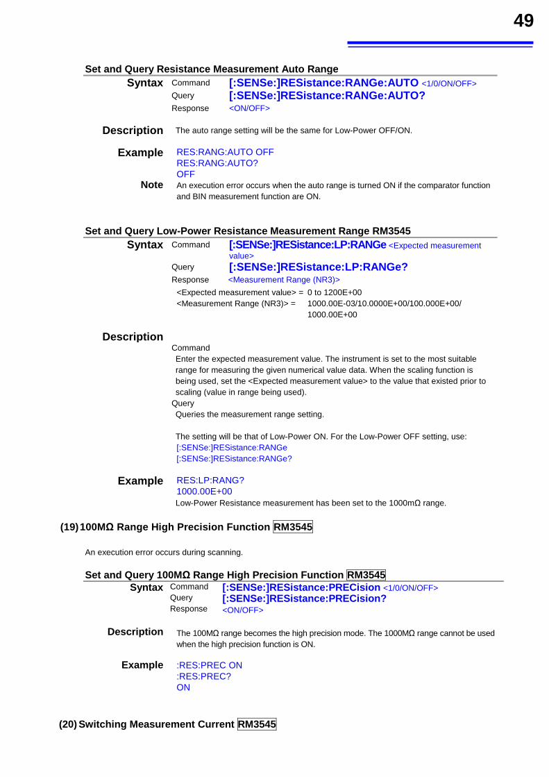
49
Set and Query Resistance Measurement Auto Range Syntax Command [:SENSe:]RESistance:RANGe:AUTO <1/0/ON/OFF>
Query [:SENSe:]RESistance:RANGe:AUTO?
Response <ON/OFF>
Description The auto range setting will be the same for Low-Power OFF/ON.
Example RES:RANG:AUTO OFF RES:RANG:AUTO? OFF
Note An execution error occurs when the auto range is turned ON if the comparator function and BIN measurement function are ON.
Set and Query Low-Power Resistance Measurement Range RM3545
Syntax Command [:SENSe:]RESistance:LP:RANGe <Expected measurement value>
Query [:SENSe:]RESistance:LP:RANGe?
Response <Measurement Range (NR3)>
<Expected measurement value> = 0 to 1200E+00 <Measurement Range (NR3)> = 1000.00E-03/10.0000E+00/100.000E+00/
1000.00E+00
Description
Command Enter the expected measurement value. The instrument is set to the most suitable range for measuring the given numerical value data. When the scaling function is being used, set the <Expected measurement value> to the value that existed prior to scaling (value in range being used).
Query Queries the measurement range setting.
The setting will be that of Low-Power ON. For the Low-Power OFF setting, use: [:SENSe:]RESistance:RANGe [:SENSe:]RESistance:RANGe?
Example RES:LP:RANG? 1000.00E+00 Low-Power Resistance measurement has been set to the 1000mΩ range.
(19) 100MΩ Range High Precision Function RM3545
An execution error occurs during scanning.
Set and Query 100MΩ Range High Precision Function RM3545 Syntax Command [:SENSe:]RESistance:PRECision <1/0/ON/OFF>
Query [:SENSe:]RESistance:PRECision?Response <ON/OFF>
Description The 100MΩ range becomes the high precision mode. The 1000MΩ range cannot be used when the high precision function is ON.
Example :RES:PREC ON :RES:PREC? ON
(20) Switching Measurement Current RM3545
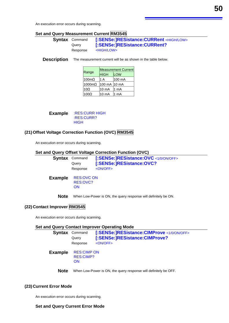
50
An execution error occurs during scanning.
Set and Query Measurement Current RM3545 Syntax Command [:SENSe:]RESistance:CURRent <HIGH/LOW>
Query [:SENSe:]RESistance:CURRent?
Response <HIGH/LOW>
Description The measurement current will be as shown in the table below.
Range Measurement CurrentHIGH LOW
100mΩ 1 A 100 mA 1000mΩ 100 mA 10 mA 10Ω 10 mA 1 mA 100Ω 10 mA 1 mA
Example :RES:CURR HIGH :RES:CURR? HIGH
(21) Offset Voltage Correction Function (OVC) RM3545
An execution error occurs during scanning.
Set and Query Offset Voltage Correction Function (OVC) Syntax Command [:SENSe:]RESistance:OVC <1/0/ON/OFF>
Query [:SENSe:]RESistance:OVC?
Response <ON/OFF>
Example RES:OVC ON RES:OVC? ON
Note When Low-Power is ON, the query response will definitely be ON.
(22) Contact Improver RM3545
An execution error occurs during scanning.
Set and Query Contact Improver Operating Mode Syntax Command [:SENSe:]RESistance:CIMProve <1/0/ON/OFF>
Query [:SENSe:]RESistance:CIMProve?
Response <ON/OFF>
Example RES:CIMP ON RES:CIMP? ON
Note When Low-Power is ON, the query response will definitely be OFF.
(23) Current Error Mode
An execution error occurs during scanning.
Set and Query Current Error Mode
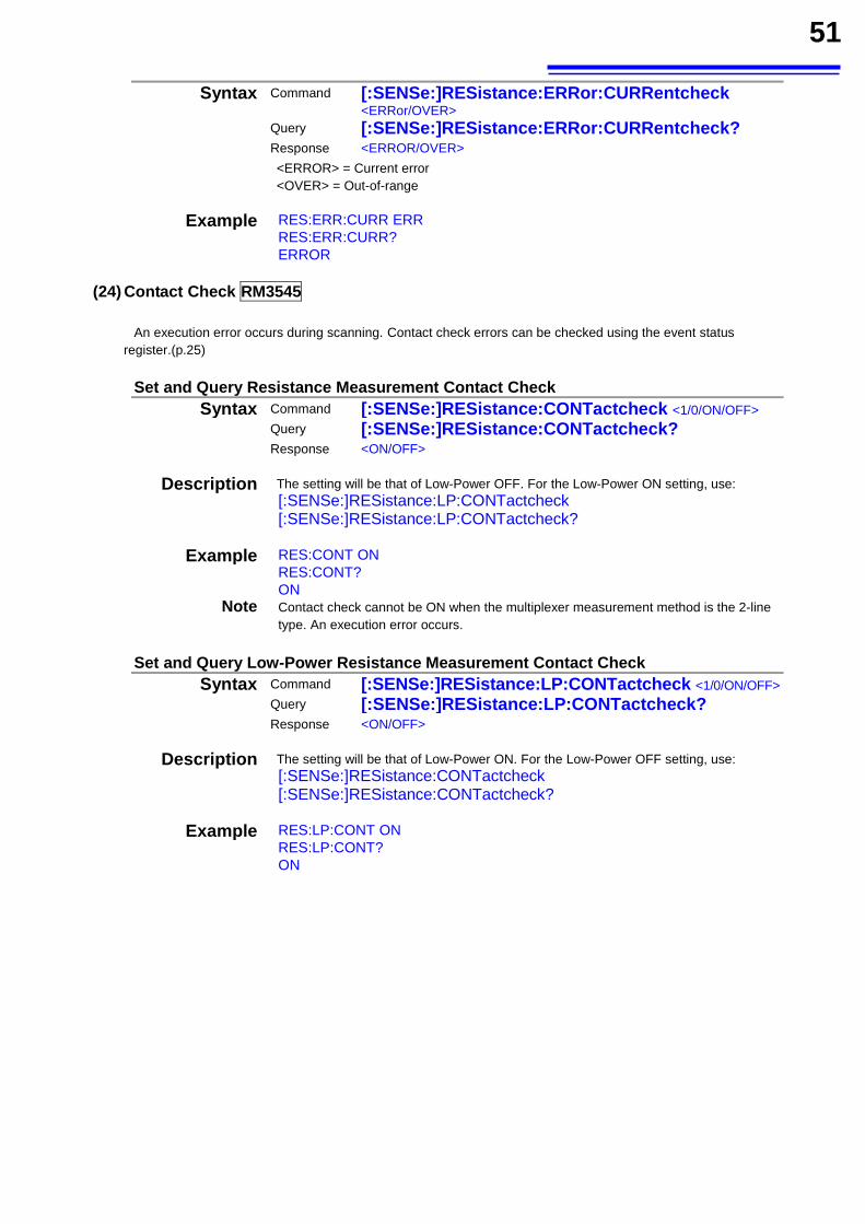
51
Syntax Command [:SENSe:]RESistance:ERRor:CURRentcheck <ERRor/OVER>
Query [:SENSe:]RESistance:ERRor:CURRentcheck? Response <ERROR/OVER>
<ERROR> = Current error <OVER> = Out-of-range
Example RES:ERR:CURR ERR RES:ERR:CURR? ERROR
(24) Contact Check RM3545 An execution error occurs during scanning. Contact check errors can be checked using the event status
register.(p.25) Set and Query Resistance Measurement Contact Check
Syntax Command [:SENSe:]RESistance:CONTactcheck <1/0/ON/OFF> Query [:SENSe:]RESistance:CONTactcheck?
Response <ON/OFF>
Description The setting will be that of Low-Power OFF. For the Low-Power ON setting, use: [:SENSe:]RESistance:LP:CONTactcheck [:SENSe:]RESistance:LP:CONTactcheck?
Example RES:CONT ON RES:CONT? ON
Note Contact check cannot be ON when the multiplexer measurement method is the 2-line type. An execution error occurs.
Set and Query Low-Power Resistance Measurement Contact Check
Syntax Command [:SENSe:]RESistance:LP:CONTactcheck <1/0/ON/OFF>Query [:SENSe:]RESistance:LP:CONTactcheck?
Response <ON/OFF>
Description The setting will be that of Low-Power ON. For the Low-Power OFF setting, use: [:SENSe:]RESistance:CONTactcheck [:SENSe:]RESistance:CONTactcheck?
Example RES:LP:CONT ON RES:LP:CONT? ON
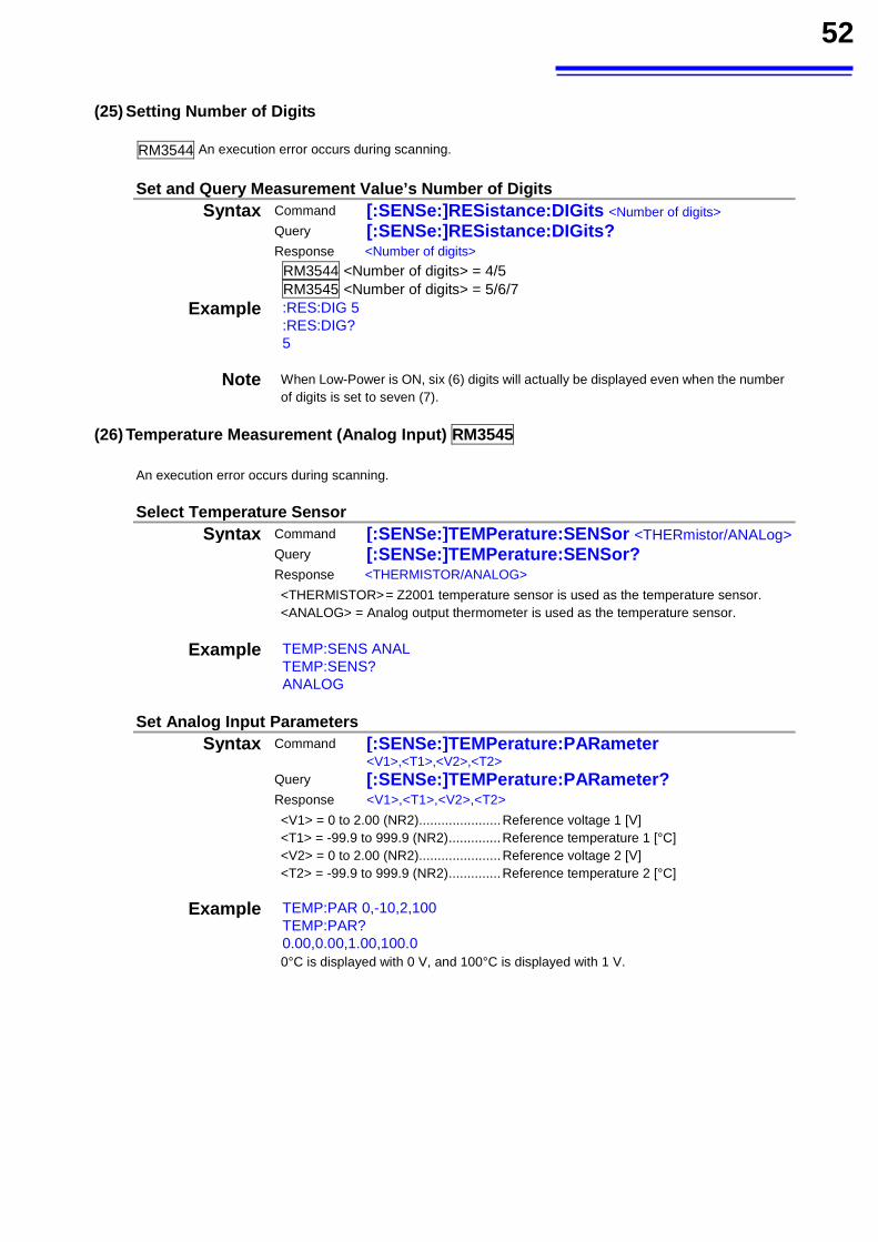
52
(25) Setting Number of Digits
RM3544 An execution error occurs during scanning.
Set and Query Measurement Value’s Number of Digits Syntax Command [:SENSe:]RESistance:DIGits <Number of digits>
Query [:SENSe:]RESistance:DIGits?
Response <Number of digits>
RM3544 <Number of digits> = 4/5 RM3545 <Number of digits> = 5/6/7
Example :RES:DIG 5 :RES:DIG? 5
Note When Low-Power is ON, six (6) digits will actually be displayed even when the number of digits is set to seven (7).
(26) Temperature Measurement (Analog Input) RM3545
An execution error occurs during scanning.
Select Temperature Sensor Syntax Command [:SENSe:]TEMPerature:SENSor <THERmistor/ANALog>
Query [:SENSe:]TEMPerature:SENSor?
Response <THERMISTOR/ANALOG>
<THERMISTOR> = Z2001 temperature sensor is used as the temperature sensor. <ANALOG> = Analog output thermometer is used as the temperature sensor.
Example TEMP:SENS ANAL TEMP:SENS? ANALOG
Set Analog Input Parameters
Syntax Command [:SENSe:]TEMPerature:PARameter <V1>,<T1>,<V2>,<T2>
Query [:SENSe:]TEMPerature:PARameter?
Response <V1>,<T1>,<V2>,<T2>
<V1> = 0 to 2.00 (NR2) ...................... Reference voltage 1 [V] <T1> = -99.9 to 999.9 (NR2) .............. Reference temperature 1 [°C] <V2> = 0 to 2.00 (NR2) ...................... Reference voltage 2 [V] <T2> = -99.9 to 999.9 (NR2) .............. Reference temperature 2 [°C]
Example TEMP:PAR 0,-10,2,100 TEMP:PAR? 0.00,0.00,1.00,100.0 0°C is displayed with 0 V, and 100°C is displayed with 1 V.
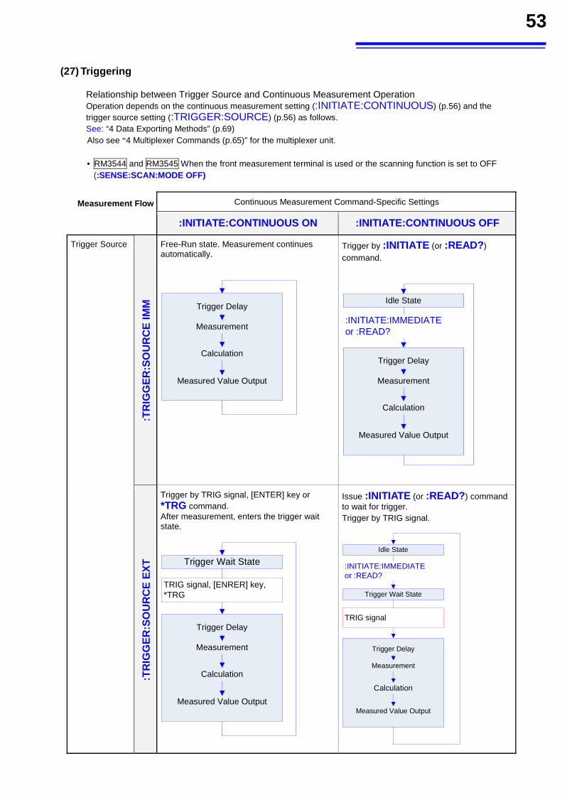
53
(27) Triggering
Relationship between Trigger Source and Continuous Measurement Operation Operation depends on the continuous measurement setting (:INITIATE:CONTINUOUS) (p.56) and the trigger source setting (:TRIGGER:SOURCE) (p.56) as follows. See: “4 Data Exporting Methods” (p.69) Also see “4 Multiplexer Commands (p.65)” for the multiplexer unit.
• RM3544 and RM3545 When the front measurement terminal is used or the scanning function is set to OFF (:SENSE:SCAN:MODE OFF)
Measurement Flow Continuous Measurement Command-Specific Settings
:INITIATE:CONTINUOUS ON :INITIATE:CONTINUOUS OFF
Trigger Source
:TR
IGG
ER
:SO
UR
CE
IMM
Free-Run state. Measurement continues automatically.
Trigger Delay
Measurement
Calculation
Measured Value Output
Trigger by :INITIATE (or :READ?) command.
Trigger Delay
Measurement
Calculation
Measured Value Output
Idle State
:INITIATE:IMMEDIATEor :READ?
:TR
IGG
ER
:SO
UR
CE
EX
T
Trigger by TRIG signal, [ENTER] key or *TRG command. After measurement, enters the trigger wait state.
Trigger Delay
Measurement
Calculation
Measured Value Output
Trigger Wait State
TRIG signal, [ENRER] key,*TRG
Issue :INITIATE (or :READ?) command to wait for trigger. Trigger by TRIG signal.
Trigger Delay
Measurement
Calculation
Measured Value Output
Trigger Wait State
TRIG signal
Idle State
:INITIATE:IMMEDIATEor :READ?
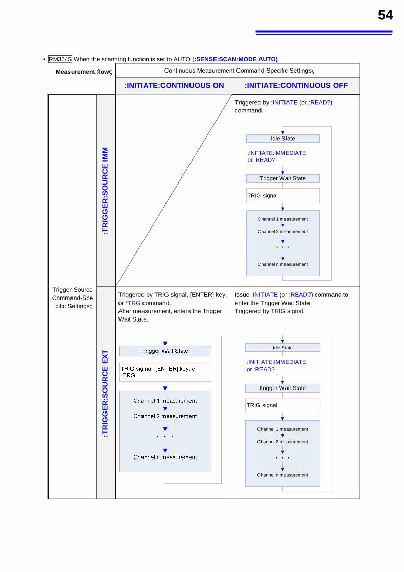
54
• RM3545 When the scanning function is set to AUTO (:SENSE:SCAN:MODE AUTO)
Measurement flow Continuous Measurement Command-Specific Settings
:INITIATE:CONTINUOUS ON :INITIATE:CONTINUOUS OFF
Trigger Source
Command-Specific Settings
:TR
IGG
ER
:SO
UR
CE
IMM
Triggered by :INITIATE (or :READ?)
command.
Channel 1 measurement
Channel 2 measurement
・・・
Channel n measurement
Trigger Wait State
TRIG signal
Idle State
:INITIATE:IMMEDIATEor :READ?
:TR
IGG
ER
:SO
UR
CE
EX
T
Triggered by TRIG signal, [ENTER] key, or *TRG command. After measurement, enters the Trigger Wait State.
Issue :INITIATE (or :READ?) command to enter the Trigger Wait State. Triggered by TRIG signal.
Channel 1 measurement
Channel 2 measurement
・・・
Channel n measurement
Trigger Wait State
TRIG signal
Idle State
:INITIATE:IMMEDIATEor :READ?
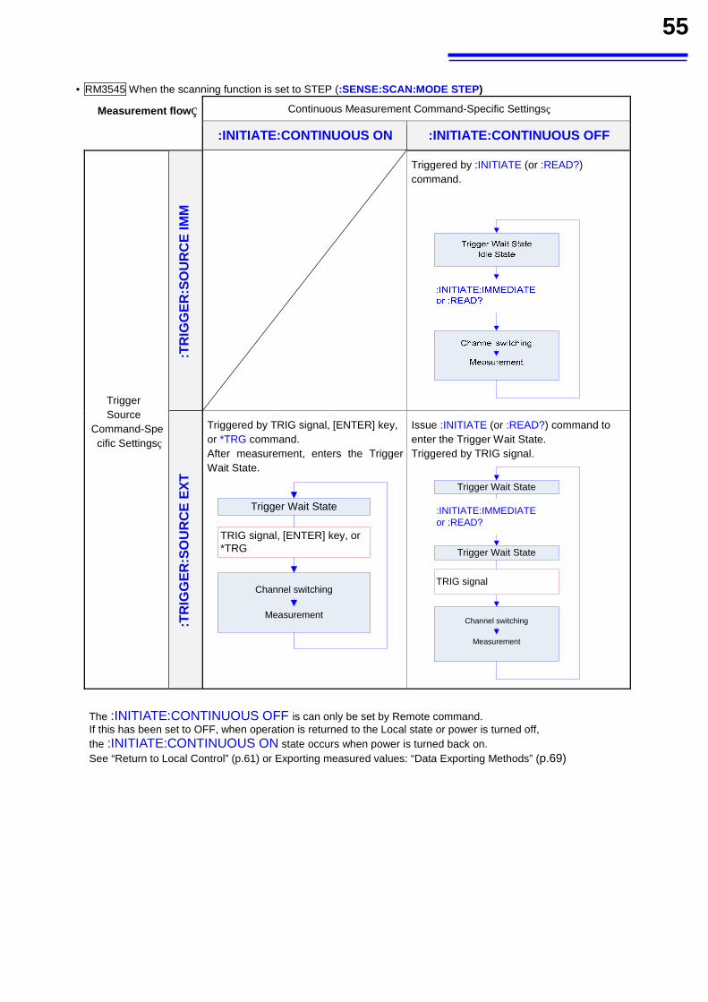
55
• RM3545 When the scanning function is set to STEP (:SENSE:SCAN:MODE STEP)
Measurement flow Continuous Measurement Command-Specific Settings
:INITIATE:CONTINUOUS ON :INITIATE:CONTINUOUS OFF
Trigger Source
Command-Specific Settings
:TR
IGG
ER
:SO
UR
CE
IMM
Triggered by :INITIATE (or :READ?) command.
:TR
IGG
ER
:SO
UR
CE
EX
T
Triggered by TRIG signal, [ENTER] key, or *TRG command. After measurement, enters the Trigger Wait State.
Channel switching
Measurement
Trigger Wait State
TRIG signal, [ENTER] key, or *TRG
Issue :INITIATE (or :READ?) command to enter the Trigger Wait State. Triggered by TRIG signal.
Channel switching
Measurement
Trigger Wait State
TRIG signal
Trigger Wait State
:INITIATE:IMMEDIATEor :READ?
The :INITIATE:CONTINUOUS OFF is can only be set by Remote command. If this has been set to OFF, when operation is returned to the Local state or power is turned off, the :INITIATE:CONTINUOUS ON state occurs when power is turned back on. See “Return to Local Control” (p.61) or Exporting measured values: “Data Exporting Methods” (p.69)
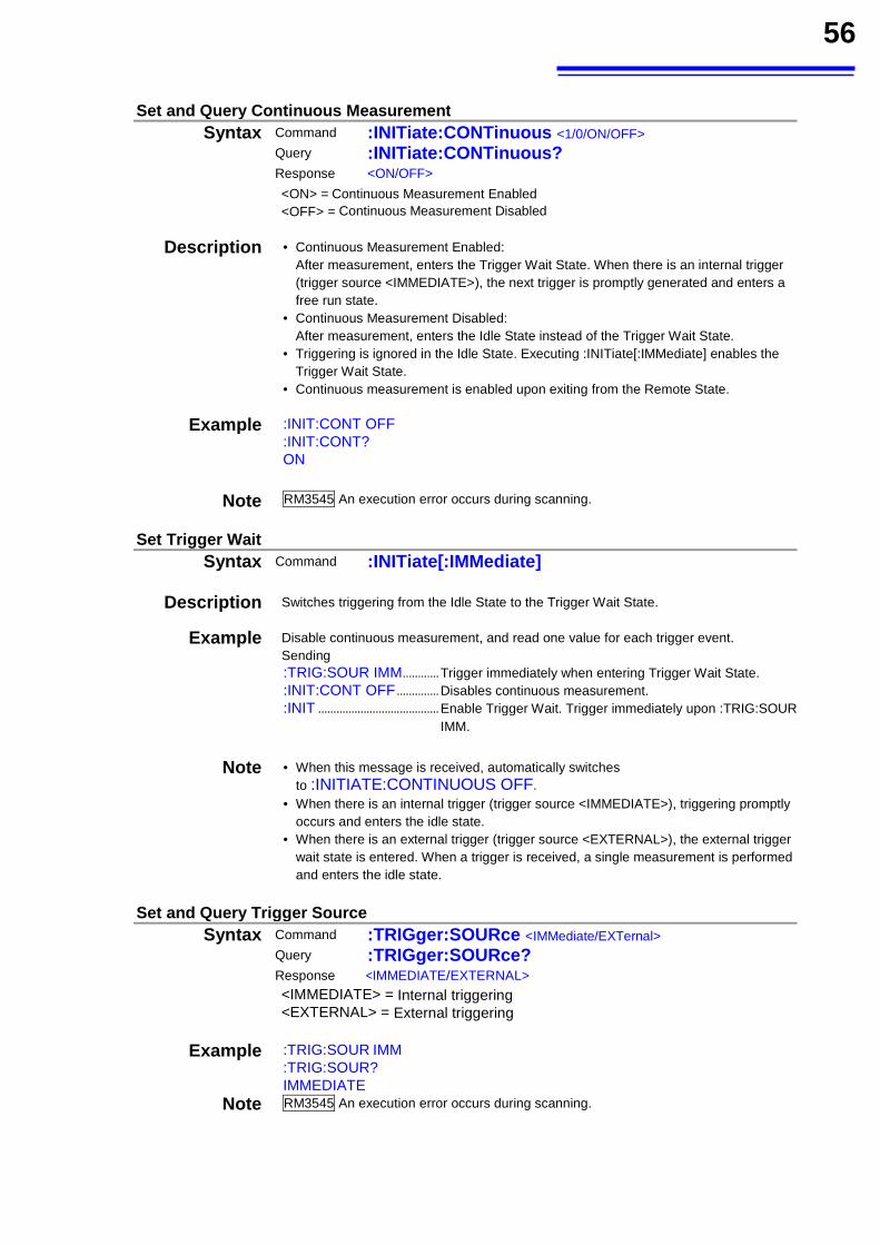
56
Set and Query Continuous Measurement Syntax Command :INITiate:CONTinuous <1/0/ON/OFF>
Query :INITiate:CONTinuous?
Response <ON/OFF>
<ON> = Continuous Measurement Enabled <OFF> = Continuous Measurement Disabled
Description • Continuous Measurement Enabled: After measurement, enters the Trigger Wait State. When there is an internal trigger
(trigger source <IMMEDIATE>), the next trigger is promptly generated and enters a free run state.
• Continuous Measurement Disabled: After measurement, enters the Idle State instead of the Trigger Wait State. • Triggering is ignored in the Idle State. Executing :INITiate[:IMMediate] enables the
Trigger Wait State. • Continuous measurement is enabled upon exiting from the Remote State.
Example :INIT:CONT OFF :INIT:CONT? ON
Note RM3545 An execution error occurs during scanning.
Set Trigger Wait Syntax Command :INITiate[:IMMediate]
Description Switches triggering from the Idle State to the Trigger Wait State.
Example Disable continuous measurement, and read one value for each trigger event. Sending :TRIG:SOUR IMM ............ Trigger immediately when entering Trigger Wait State. :INIT:CONT OFF .............. Disables continuous measurement. :INIT ........................................ Enable Trigger Wait. Trigger immediately upon :TRIG:SOUR
IMM.
Note • When this message is received, automatically switches
to :INITIATE:CONTINUOUS OFF. • When there is an internal trigger (trigger source <IMMEDIATE>), triggering promptly
occurs and enters the idle state. • When there is an external trigger (trigger source <EXTERNAL>), the external trigger
wait state is entered. When a trigger is received, a single measurement is performed and enters the idle state.
Set and Query Trigger Source
Syntax Command :TRIGger:SOURce <IMMediate/EXTernal> Query :TRIGger:SOURce?
Response <IMMEDIATE/EXTERNAL>
<IMMEDIATE> = Internal triggering <EXTERNAL> = External triggering
Example :TRIG:SOUR IMM :TRIG:SOUR? IMMEDIATE
Note RM3545 An execution error occurs during scanning.
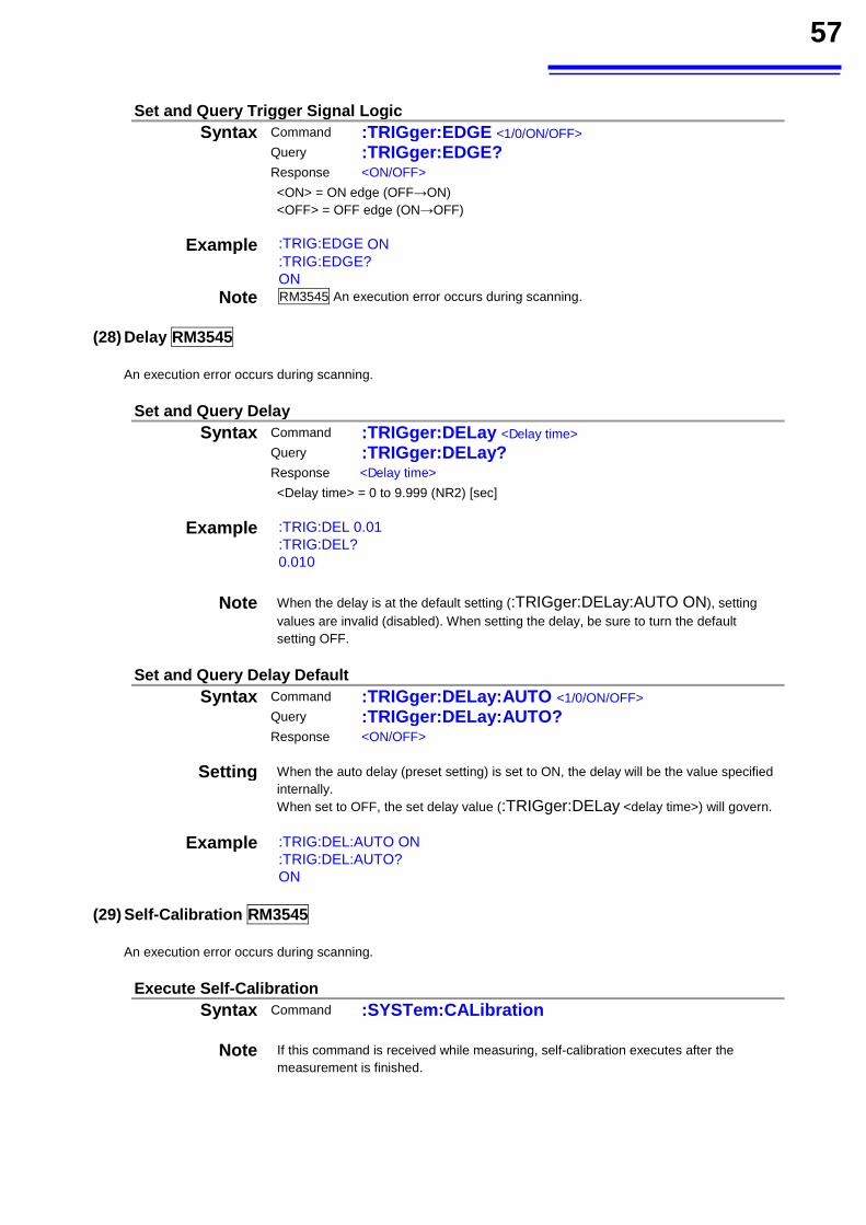
57
Set and Query Trigger Signal Logic
Syntax Command :TRIGger:EDGE <1/0/ON/OFF> Query :TRIGger:EDGE?
Response <ON/OFF>
<ON> = ON edge (OFF→ON) <OFF> = OFF edge (ON→OFF)
Example :TRIG:EDGE ON :TRIG:EDGE? ON
Note RM3545 An execution error occurs during scanning.
(28) Delay RM3545
An execution error occurs during scanning.
Set and Query Delay Syntax Command :TRIGger:DELay <Delay time>
Query :TRIGger:DELay?
Response <Delay time>
<Delay time> = 0 to 9.999 (NR2) [sec]
Example :TRIG:DEL 0.01 :TRIG:DEL? 0.010
Note When the delay is at the default setting (:TRIGger:DELay:AUTO ON), setting values are invalid (disabled). When setting the delay, be sure to turn the default setting OFF.
Set and Query Delay Default
Syntax Command :TRIGger:DELay:AUTO <1/0/ON/OFF> Query :TRIGger:DELay:AUTO?
Response <ON/OFF>
Setting When the auto delay (preset setting) is set to ON, the delay will be the value specified internally. When set to OFF, the set delay value (:TRIGger:DELay <delay time>) will govern.
Example :TRIG:DEL:AUTO ON :TRIG:DEL:AUTO? ON
(29) Self-Calibration RM3545
An execution error occurs during scanning.
Execute Self-Calibration Syntax Command :SYSTem:CALibration
Note If this command is received while measuring, self-calibration executes after the
measurement is finished.
58
Execute and Set Self-Calibration
Syntax Command :SYSTem:CALibration:AUTO <1/0/ON/OFF> Query :SYSTem:CALibration:AUTO?
Response <ON/OFF>
<ON> = AUTO Self-Calibration selected <OFF> = MANUAL Self-Calibration selected
Example :SYST:CAL:AUTO OFF :SYST:CAL:AUTO? OFF
Note Even when AUTO Self-Calibration is selected, Self-Calibration can be manually performed at any time by sending the :SYSTem:CALibration command.
(30) Saving and Reading Measurement Conditions
RM3545 An execution error occurs during scanning.
Save and Read Measurement Conditions Syntax Command :SYSTem:PANel:SAVE <Table No>
:SYSTem:PANel:LOAD <Table No>,<Zero adjustment load> RM3544 <Table No> = 1 to 10
RM3545 <Table No> = 1 to 30 When the front terminal is used as a measurement terminal.)/ 31 to 38 (When the multiplexer is used as a measurement terminal.)
<Zero adjustment load> = 1/0/ON/OFF <ON> = Zero adjustment value is also read during panel loading. <OFF> = Zero adjustment is not read during panel loading.
Example :SYST:PAN:SAVE 10
:SYST:PAN:LOAD 5,OFF
Note When the measurement conditions for the Table No. have already been saved and :SYSTem:PANel:SAVE is executed, the measurement conditions will be overwritten. When the Table No. that does not have the measurement conditions is specified and :SYSTem: PANel:LOAD is executed., an execution error will occur. RM3545 When the front terminal is used as a measurement terminal, the measurement conditions cannot be saved to 31 to 38. When the multiplexer is used, the measurement conditions cannot be saved to 1 to 30. When a test lead is connected to the front measurement terminal, cannot be read to 31 to 38.An execution error occurs in either case.
Set and Query Panel Name
Syntax Command :SYSTem:PANel:NAME <Table No>,<Panel name (character string data: maximum 10 characters)>
Query :SYSTem:PANel:NAME? <Table No>
Response <Table No>,<Panel name (character string data: maximum 10 characters)>
RM3544 <Table No> = 1 to 10 RM3545 <Table No> = 1 to 38 For information on character string data, see Data Formats. (p.4)
Example :SYST:PAN:NAME 1,“PANEL_1” :SYST:PAN:NAME? 1 1,“PANEL_1”
59
Clear Panel
Syntax Command :SYSTem:PANel:CLEar <Table No>
RM3544 <Table No> = 1 to 10 RM3545 <Table No> = 1 to 38
Example :SYST:PAN:CLE 10
(31) Key-Lock
RM3545 An execution error occurs during scanning.
Set and Query Key-Lock State
Syntax Command :SYSTem:KLOCk <1/0/ON/OFF> Query :SYSTem:KLOCk?
Response <ON/MENUOFF>
Description Switches to FULL key-lock state. (Prohibits all setting changes by key operation.) MENU is returned during MENU key-lock state. the scanning and the measuring.
Example :SYST:KLOC ON :SYST:KLOCK? ON
(32) Line Frequency
RM3545 An execution error occurs during scanning.
Set and Query Line Frequency
Syntax Command :SYSTem:LFRequency <AUTO/50/60> Query :SYSTem:LFRequency?
Response <AUTO/50/60>
Example :SYST:LFR 50 :SYST:LFR? 50
60
(33) Clock RM3545
An execution error occurs during scanning.
Set and Query System Date Syntax Command :SYSTem:DATE <Year>,<Month>,<Day>
Query :SYSTem:DATE?
Response <Year>,<Month>,<Day>
<Year> = 00 to 99 <Month> = 01 to 12 <Day> = 01 to 31
Description Sets and queries the date of the real-time system clock.
Example :SYST:DATE 13,01,10 Sets the date to January 10, 2013. :SYST:DATE? 13,12,10 The date is December 10, 2013.
Note Attempting to set an out-of-range numerical value returns an execution error. Attempting to set a non-existent date (such as 13,06,31) returns an execution error.
Set and Query System Time
Syntax Command :SYSTem:TIME <Hour>,<Minute>,<Second>
Query :SYSTem:TIME?
Response <Hour>,<Minute>,<Second>
<Hour> = 00 to 23 <Minute> = 00 to 59 <Second> = 00 to 59
Description Sets the time of the real-time system clock.
Example :SYST:TIME 08,25,00 Sets the time to 8:25 and 00 seconds. :SYST:TIME? 23,09,53 The time is 23:09 and 53 seconds.
Note Attempting to set an out-of-range numerical value returns an execution error. Attempting to set a non-existent time (such as 09,06,71) returns an execution error.
(34) Key Beeper
RM3545 An execution error occurs during scanning.
Set and Query Key Beeper Syntax Command :SYSTem:BEEPer:STATe <1/0/ON/OFF>
Query :SYSTem:BEEPer:STATe?
Response <ON/OFF>
Example :SYST:BEEP:STAT ON :SYST:BEEP:STAT? ON
61
(35) Communications Settings
RM3545 An execution error occurs during scanning.
Return to Local Control Syntax Command :SYSTem:LOCal
Description Disables communications remote control and re-enables local control. The panel keys
are re-enabled.
Example :SYST:LOC
Set and Query Measurement-Synchronized Data Output [RS-232C/USB]
Syntax Command :SYSTem:DATAout <1/0/ON/OFF> Query :SYSTem:DATAout?
Response <ON/OFF>
Description <ON> = With an external trigger (trigger source <EXTERNAL>), measurement values are automatically sent when trigger measurements are completed.
When there is an internal trigger (trigger source <IMMEDIATE>), measurement values are automatically sent when the [ENTER] key is pressed and TRIG signal have been input.
<OFF> = Measured values are not automatically sent.
Note This command is not applicable to the GP-IB Interface.
Set and Query Header Presence Syntax Command :SYSTem:HEADer <1/0/ON/OFF>
Query :SYSTem:HEADer? Response <ON/OFF>
Example :SYST:HEAD ON :SYST:HEAD? :SYSTEM:HEADER ON :SYST:HEAD OFF :SYST:HEAD? OFF
Note When turning the power on or after the *RST command, this is initialized to OFF (no header).
Set Delimiter [GP-IB] Syntax Command :SYSTem:TERMinator <0/1>
Query :SYSTem:TERMinator? Response <0/1>
<0> = LF+EOI <1> = CR, LF+EOI
Example :SYST:TERM 1 :SYST:TERM? 0
Note • At power-on, this is set to 0 (LF+EOI). • The RS-232C/USB delimiter is fixed as CR+LF.
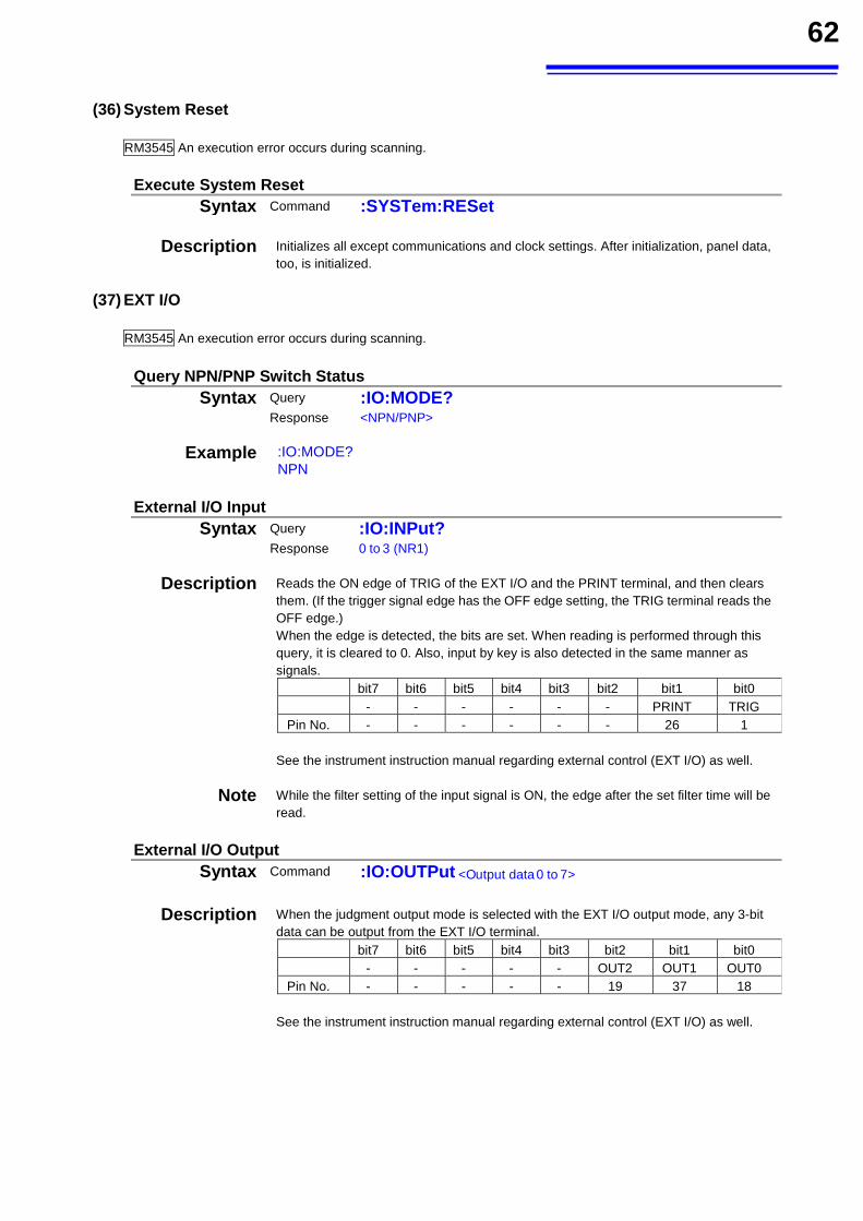
62
(36) System Reset
RM3545 An execution error occurs during scanning.
Execute System Reset Syntax Command :SYSTem:RESet
Description Initializes all except communications and clock settings. After initialization, panel data,
too, is initialized.
(37) EXT I/O
RM3545 An execution error occurs during scanning.
Query NPN/PNP Switch Status
Syntax Query :IO:MODE?
Response <NPN/PNP>
Example :IO:MODE? NPN
External I/O Input
Syntax Query :IO:INPut? Response 0 to 3 (NR1)
Description Reads the ON edge of TRIG of the EXT I/O and the PRINT terminal, and then clears them. (If the trigger signal edge has the OFF edge setting, the TRIG terminal reads the OFF edge.) When the edge is detected, the bits are set. When reading is performed through this query, it is cleared to 0. Also, input by key is also detected in the same manner as signals.
bit7 bit6 bit5 bit4 bit3 bit2 bit1 bit0 - - - - - - PRINT TRIG Pin No. - - - - - - 26 1
See the instrument instruction manual regarding external control (EXT I/O) as well.
Note While the filter setting of the input signal is ON, the edge after the set filter time will be read.
External I/O Output
Syntax Command :IO:OUTPut <Output data 0 to 7>
Description When the judgment output mode is selected with the EXT I/O output mode, any 3-bit
data can be output from the EXT I/O terminal. bit7 bit6 bit5 bit4 bit3 bit2 bit1 bit0 - - - - - OUT2 OUT1 OUT0
Pin No. - - - - - 19 37 18
See the instrument instruction manual regarding external control (EXT I/O) as well.
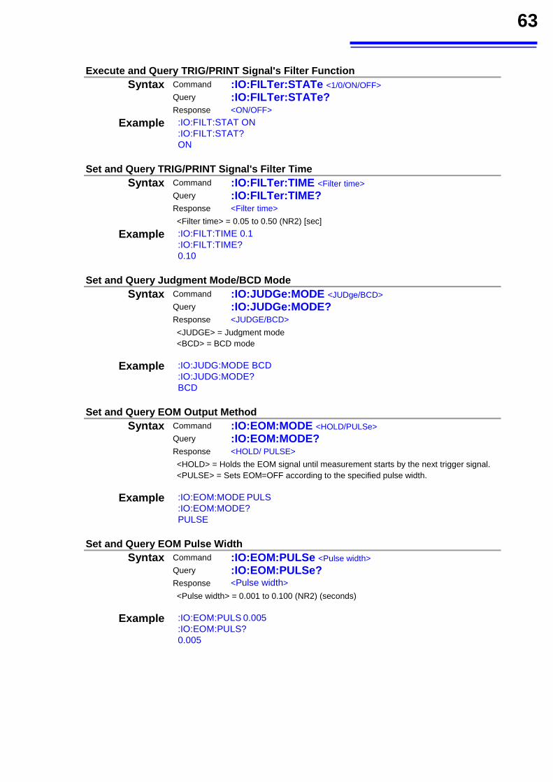
63
Execute and Query TRIG/PRINT Signal's Filter Function
Syntax Command :IO:FILTer:STATe <1/0/ON/OFF> Query :IO:FILTer:STATe?
Response <ON/OFF>
Example :IO:FILT:STAT ON :IO:FILT:STAT? ON
Set and Query TRIG/PRINT Signal's Filter Time
Syntax Command :IO:FILTer:TIME <Filter time>
Query :IO:FILTer:TIME?
Response <Filter time>
<Filter time> = 0.05 to 0.50 (NR2) [sec]
Example :IO:FILT:TIME 0.1 :IO:FILT:TIME? 0.10
Set and Query Judgment Mode/BCD Mode
Syntax Command :IO:JUDGe:MODE <JUDge/BCD>
Query :IO:JUDGe:MODE?
Response <JUDGE/BCD>
<JUDGE> = Judgment mode <BCD> = BCD mode
Example :IO:JUDG:MODE BCD :IO:JUDG:MODE? BCD
Set and Query EOM Output Method
Syntax Command :IO:EOM:MODE <HOLD/PULSe> Query :IO:EOM:MODE?
Response <HOLD/ PULSE>
<HOLD> = Holds the EOM signal until measurement starts by the next trigger signal. <PULSE> = Sets EOM=OFF according to the specified pulse width.
Example :IO:EOM:MODE PULS :IO:EOM:MODE? PULSE
Set and Query EOM Pulse Width
Syntax Command :IO:EOM:PULSe <Pulse width>
Query :IO:EOM:PULSe?
Response <Pulse width>
<Pulse width> = 0.001 to 0.100 (NR2) (seconds)
Example :IO:EOM:PULS 0.005 :IO:EOM:PULS? 0.005
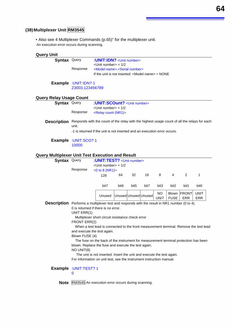
64
(38) Multiplexer Unit RM3545
• Also see 4 Multiplexer Commands (p.65)” for the multiplexer unit. An execution error occurs during scanning.
Query Unit
Syntax Query :UNIT:IDN? <Unit number> <Unit number> = 1/2
Response <Model name>,<Serial number>
If the unit is not inserted: <Model name> = NONE
Example :UNIT:IDN? 1 Z3003,123456789
Query Multiplexer Unit Test Execution and Result
Syntax Query :UNIT:TEST? <Unit number> <Unit number> = 1/2
Response <0 to 8 (NR1)>
128
64 32 16 8 4 2 1
bit7 bit6 bit5 bit7 bit3 bit2 bit1 bit0
Unused Unused Unused UnusedNO
UNIT Blown FUSE
FRONT ERR
UNIT ERR
Description Performs a multiplexer test and responds with the result in NR1 number (0 to 4). 0 is returned if there is no error. UNIT ERR(1)
Multiplexer short circuit resistance check error FRONT ERR(2)
When a test lead is connected to the front measurement terminal. Remove the test lead and execute the test again. Blown FUSE (4) The fuse on the back of the instrument for measurement terminal protection has been blown. Replace the fuse and execute the test again. NO UNIT(8) The unit is not inserted. Insert the unit and execute the test again. For information on unit test, see the instrument instruction manual.
Example :UNIT:TEST? 1 0
Note RM3545 An execution error occurs during scanning.
Query Relay Usage Count Syntax Query :UNIT:SCOunt? <Unit number>
<Unit number> = 1/2 Response <Relay count (NR1)>
Description Responds with the count of the relay with the highest usage count of all the relays for each unit.
-1 is returned if the unit is not inserted and an execution error occurs.
Example :UNIT:SCO? 1 10000
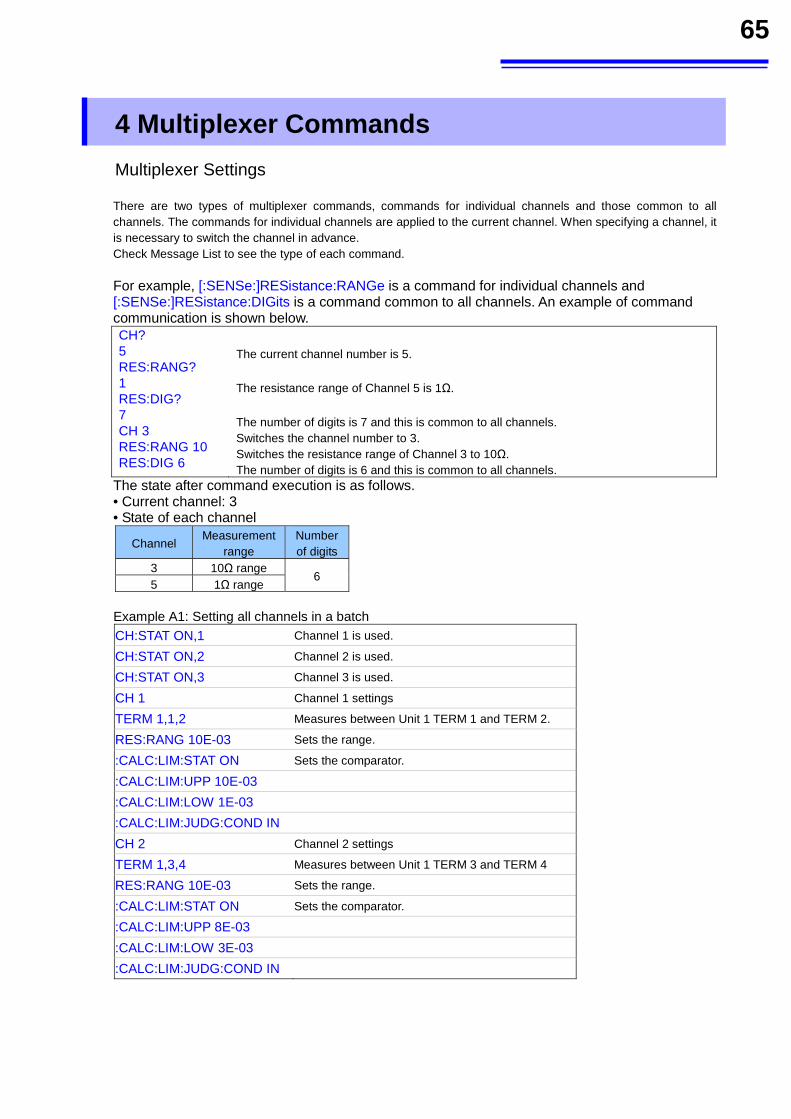
65
4 Multiplexer Commands
Multiplexer Settings
There are two types of multiplexer commands, commands for individual channels and those common to all channels. The commands for individual channels are applied to the current channel. When specifying a channel, it is necessary to switch the channel in advance. Check Message List to see the type of each command.
For example, [:SENSe:]RESistance:RANGe is a command for individual channels and [:SENSe:]RESistance:DIGits is a command common to all channels. An example of command communication is shown below. CH? 5 RES:RANG? 1 RES:DIG? 7 CH 3 RES:RANG 10 RES:DIG 6
The current channel number is 5. The resistance range of Channel 5 is 1Ω.
The number of digits is 7 and this is common to all channels. Switches the channel number to 3. Switches the resistance range of Channel 3 to 10Ω. The number of digits is 6 and this is common to all channels.
The state after command execution is as follows. • Current channel: 3 • State of each channel
Channel Measurement range
Number of digits
3 10Ω range 6
5 1Ω range
Example A1: Setting all channels in a batch
CH:STAT ON,1 Channel 1 is used. CH:STAT ON,2 Channel 2 is used. CH:STAT ON,3 Channel 3 is used. CH 1 Channel 1 settings TERM 1,1,2 Measures between Unit 1 TERM 1 and TERM 2. RES:RANG 10E-03 Sets the range. :CALC:LIM:STAT ON Sets the comparator. :CALC:LIM:UPP 10E-03
:CALC:LIM:LOW 1E-03
:CALC:LIM:JUDG:COND IN
CH 2 Channel 2 settings TERM 1,3,4 Measures between Unit 1 TERM 3 and TERM 4 RES:RANG 10E-03 Sets the range. :CALC:LIM:STAT ON Sets the comparator. :CALC:LIM:UPP 8E-03
:CALC:LIM:LOW 3E-03
:CALC:LIM:JUDG:COND IN
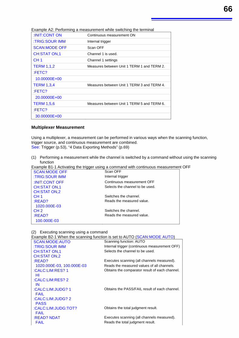
66
Example A2: Performing a measurement while switching the terminal :INIT:CONT ON Continuous measurement ON :TRIG:SOUR IMM Internal trigger SCAN:MODE OFF Scan OFF CH:STAT ON,1 Channel 1 is used. CH 1 Channel 1 settings TERM 1,1,2 Measures between Unit 1 TERM 1 and TERM 2. :FETC?
10.00000E+00
TERM 1,3,4 Measures between Unit 1 TERM 3 and TERM 4. :FETC?
20.00000E+00
TERM 1,5,6 Measures between Unit 1 TERM 5 and TERM 6. :FETC?
30.00000E+00
Multiplexer Measurement
Using a multiplexer, a measurement can be performed in various ways when the scanning function, trigger source, and continuous measurement are combined. See: Trigger (p.53), “4 Data Exporting Methods” (p.69)
(1) Performing a measurement while the channel is switched by a command without using the scanning function
Example B1-1 Activating the trigger using a command with continuous measurement OFF SCAN:MODE OFF Scan OFF
:TRIG:SOUR IMM Internal trigger
:INIT:CONT OFF Continuous measurement OFF
CH:STAT ON,1 Selects the channel to be used.CH:STAT ON,2
CH 1 Switches the channel.:READ? Reads the measured value.
1020.000E-03
CH 2 Switches the channel.:READ? Reads the measured value.
100.000E-03
(2) Executing scanning using a command Example B2-1 When the scanning function is set to AUTO (SCAN:MODE AUTO) SCAN:MODE:AUTO Scanning function: AUTO
:TRIG:SOUR IMM Internal trigger (continuous measurement OFF) CH:STAT ON,1 Selects the channel to be used.CH:STAT ON,2
:READ? Executes scanning (all channels measured). 1020.000E-03, 100.000E-03 Reads the measured values of all channels.
:CALC:LIM:RES? 1 HI
:CALC:LIM:RES? 2 IN
Obtains the comparator result of each channel.
:CALC:LIM:JUDG? 1 FAIL
:CALC:LIM:JUDG? 2 PASS
Obtains the PASS/FAIL result of each channel.
:CALC:LIM:JUDG:TOT? FAIL
Obtains the total judgment result.
:READ? NDAT Executes scanning (all channels measured). FAIL Reads the total judgment result.
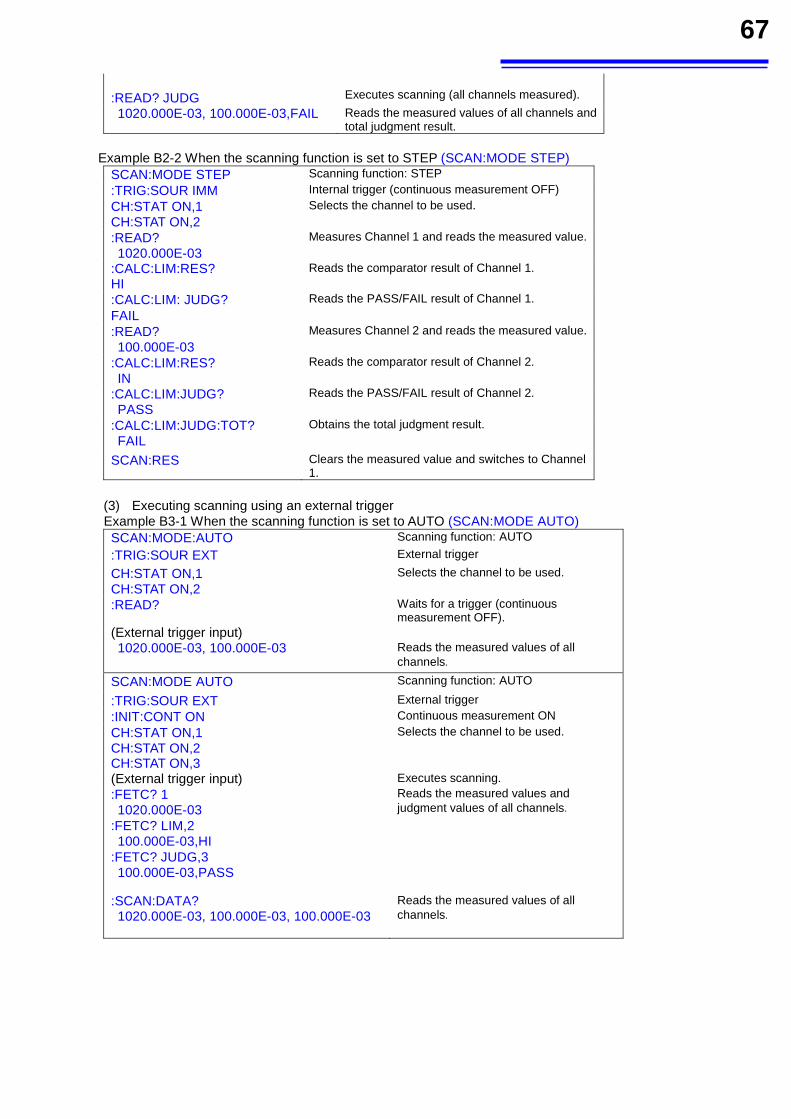
67
:READ? JUDG
Executes scanning (all channels measured).
1020.000E-03, 100.000E-03,FAIL Reads the measured values of all channels and total judgment result.
Example B2-2 When the scanning function is set to STEP (SCAN:MODE STEP)
SCAN:MODE STEP Scanning function: STEP
:TRIG:SOUR IMM Internal trigger (continuous measurement OFF)
CH:STAT ON,1 CH:STAT ON,2
Selects the channel to be used.
:READ? 1020.000E-03
Measures Channel 1 and reads the measured value.
:CALC:LIM:RES? HI
Reads the comparator result of Channel 1.
:CALC:LIM: JUDG? FAIL
Reads the PASS/FAIL result of Channel 1.
:READ? 100.000E-03
Measures Channel 2 and reads the measured value.
:CALC:LIM:RES? IN
Reads the comparator result of Channel 2.
:CALC:LIM:JUDG? PASS
Reads the PASS/FAIL result of Channel 2.
:CALC:LIM:JUDG:TOT? FAIL
Obtains the total judgment result.
SCAN:RES Clears the measured value and switches to Channel 1.
(3) Executing scanning using an external trigger Example B3-1 When the scanning function is set to AUTO (SCAN:MODE AUTO) SCAN:MODE:AUTO Scanning function: AUTO
:TRIG:SOUR EXT External trigger
CH:STAT ON,1 CH:STAT ON,2
Selects the channel to be used.
:READ? Waits for a trigger (continuous measurement OFF).
(External trigger input)
1020.000E-03, 100.000E-03
Reads the measured values of all channels.
SCAN:MODE AUTO Scanning function: AUTO
:TRIG:SOUR EXT External trigger
:INIT:CONT ON Continuous measurement ON
CH:STAT ON,1 CH:STAT ON,2 CH:STAT ON,3
Selects the channel to be used.
(External trigger input) Executes scanning.:FETC? 1 1020.000E-03
:FETC? LIM,2 100.000E-03,HI
:FETC? JUDG,3 100.000E-03,PASS
Reads the measured values and judgment values of all channels.
:SCAN:DATA? 1020.000E-03, 100.000E-03, 100.000E-03
Reads the measured values of all channels.
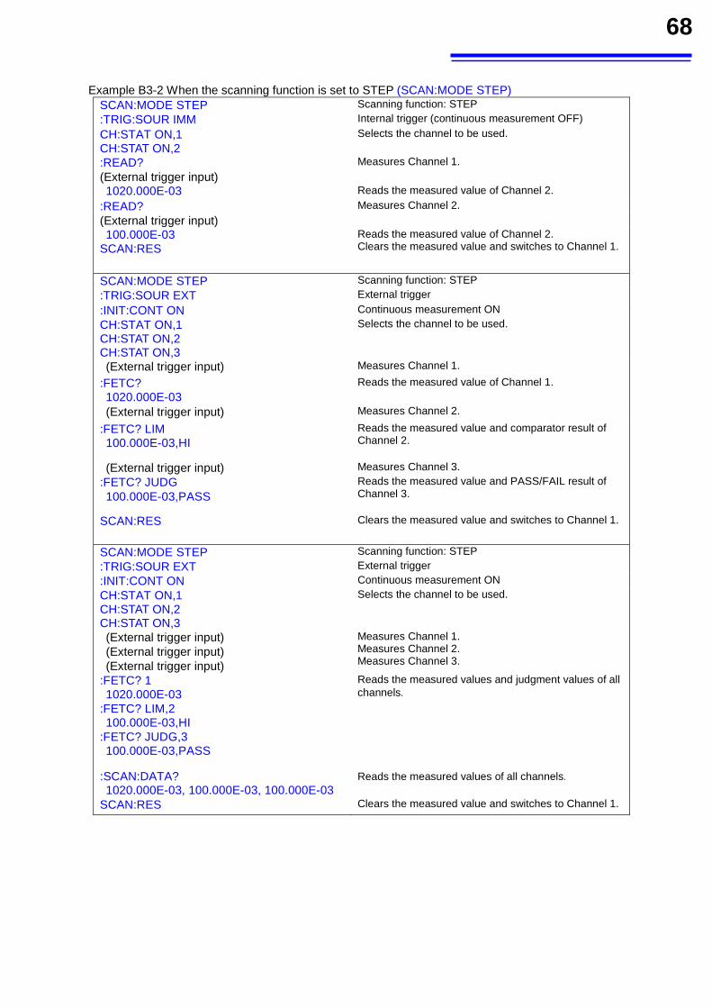
68
Example B3-2 When the scanning function is set to STEP (SCAN:MODE STEP)
SCAN:MODE STEP Scanning function: STEP
:TRIG:SOUR IMM Internal trigger (continuous measurement OFF) CH:STAT ON,1 CH:STAT ON,2
Selects the channel to be used.
:READ? Measures Channel 1.
(External trigger input)
1020.000E-03 Reads the measured value of Channel 2. :READ? Measures Channel 2.
(External trigger input)
100.000E-03 SCAN:RES
Reads the measured value of Channel 2. Clears the measured value and switches to Channel 1.
SCAN:MODE STEP Scanning function: STEP
:TRIG:SOUR EXT External trigger
:INIT:CONT ON Continuous measurement ON
CH:STAT ON,1 CH:STAT ON,2 CH:STAT ON,3
Selects the channel to be used.
(External trigger input) Measures Channel 1.
:FETC? 1020.000E-03
Reads the measured value of Channel 1.
(External trigger input) Measures Channel 2.
:FETC? LIM 100.000E-03,HI
Reads the measured value and comparator result of Channel 2.
(External trigger input) Measures Channel 3.
:FETC? JUDG 100.000E-03,PASS
Reads the measured value and PASS/FAIL result of Channel 3.
SCAN:RES
Clears the measured value and switches to Channel 1.
SCAN:MODE STEP Scanning function: STEP
:TRIG:SOUR EXT External trigger
:INIT:CONT ON Continuous measurement ON
CH:STAT ON,1 CH:STAT ON,2 CH:STAT ON,3
Selects the channel to be used.
(External trigger input) (External trigger input) (External trigger input)
Measures Channel 1.Measures Channel 2. Measures Channel 3.
:FETC? 1 1020.000E-03
:FETC? LIM,2 100.000E-03,HI
:FETC? JUDG,3 100.000E-03,PASS
Reads the measured values and judgment values of all channels.
:SCAN:DATA? 1020.000E-03, 100.000E-03, 100.000E-03
Reads the measured values of all channels.
SCAN:RES Clears the measured value and switches to Channel 1.
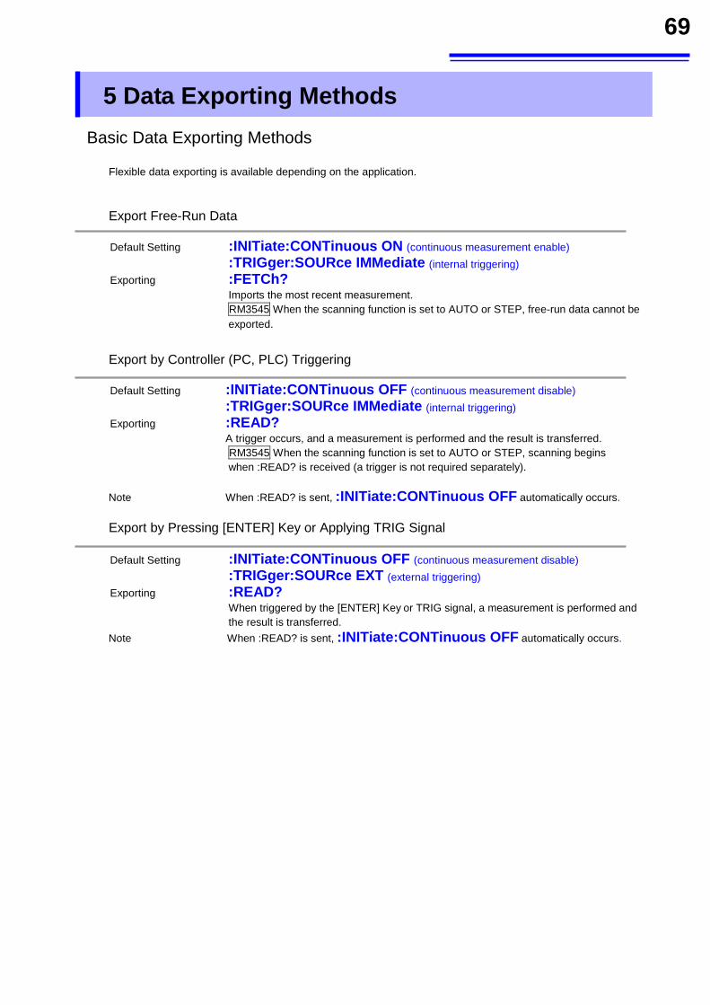
69
5 Data Exporting Methods
Basic Data Exporting Methods
Flexible data exporting is available depending on the application.
Export Free-Run Data
Default Setting :INITiate:CONTinuous ON (continuous measurement enable)
:TRIGger:SOURce IMMediate (internal triggering)
Exporting :FETCh? Imports the most recent measurement.
RM3545 When the scanning function is set to AUTO or STEP, free-run data cannot be exported.
Export by Controller (PC, PLC) Triggering
Default Setting :INITiate:CONTinuous OFF (continuous measurement disable)
:TRIGger:SOURce IMMediate (internal triggering)
Exporting :READ? A trigger occurs, and a measurement is performed and the result is transferred.
RM3545 When the scanning function is set to AUTO or STEP, scanning begins when :READ? is received (a trigger is not required separately).
Note When :READ? is sent, :INITiate:CONTinuous OFF automatically occurs.
Export by Pressing [ENTER] Key or Applying TRIG Signal
Default Setting :INITiate:CONTinuous OFF (continuous measurement disable)
:TRIGger:SOURce EXT (external triggering)
Exporting :READ? When triggered by the [ENTER] Key or TRIG signal, a measurement is performed and
the result is transferred.
Note When :READ? is sent, :INITiate:CONTinuous OFF automatically occurs.
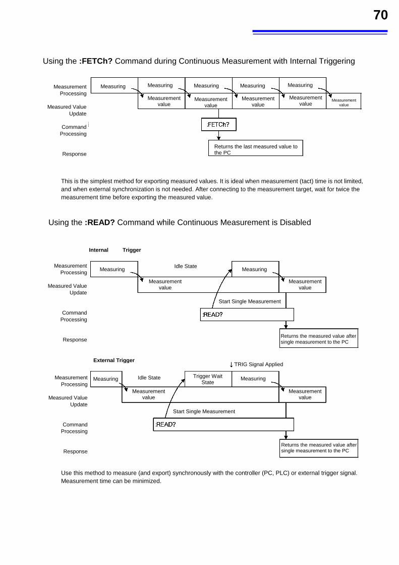
70
Using the :FETCh? Command during Continuous Measurement with Internal Triggering
This is the simplest method for exporting measured values. It is ideal when measurement (tact) time is not limited, and when external synchronization is not needed. After connecting to the measurement target, wait for twice the measurement time before exporting the measured value.
Using the :READ? Command while Continuous Measurement is Disabled
Use this method to measure (and export) synchronously with the controller (PC, PLC) or external trigger signal. Measurement time can be minimized.
Measurement Processing
Measured Value
Update
Command Processing
Response
Measuring Measuring Measuring Measuring Measuring Measurement
value Measurement
value Measurement
value Measurement
value Measurement
value
Returns the last measured value to the PC
Measurement Processing
Measured Value
Update
Command Processing
Response
Measurement Processing
Measured Value
Update
Command Processing
Response
Measuring Measuring
MeasuringMeasuring
Measurement value
Measurement value
Measurement value
Measurement value
Internal Trigger Case
External Trigger Case
Idle State
Idle State Trigger Wait State
TRIG Signal Applied
Start Single Measurement
Returns the measured value after single measurement to the PC
Start Single Measurement
Returns the measured value after single measurement to the PC
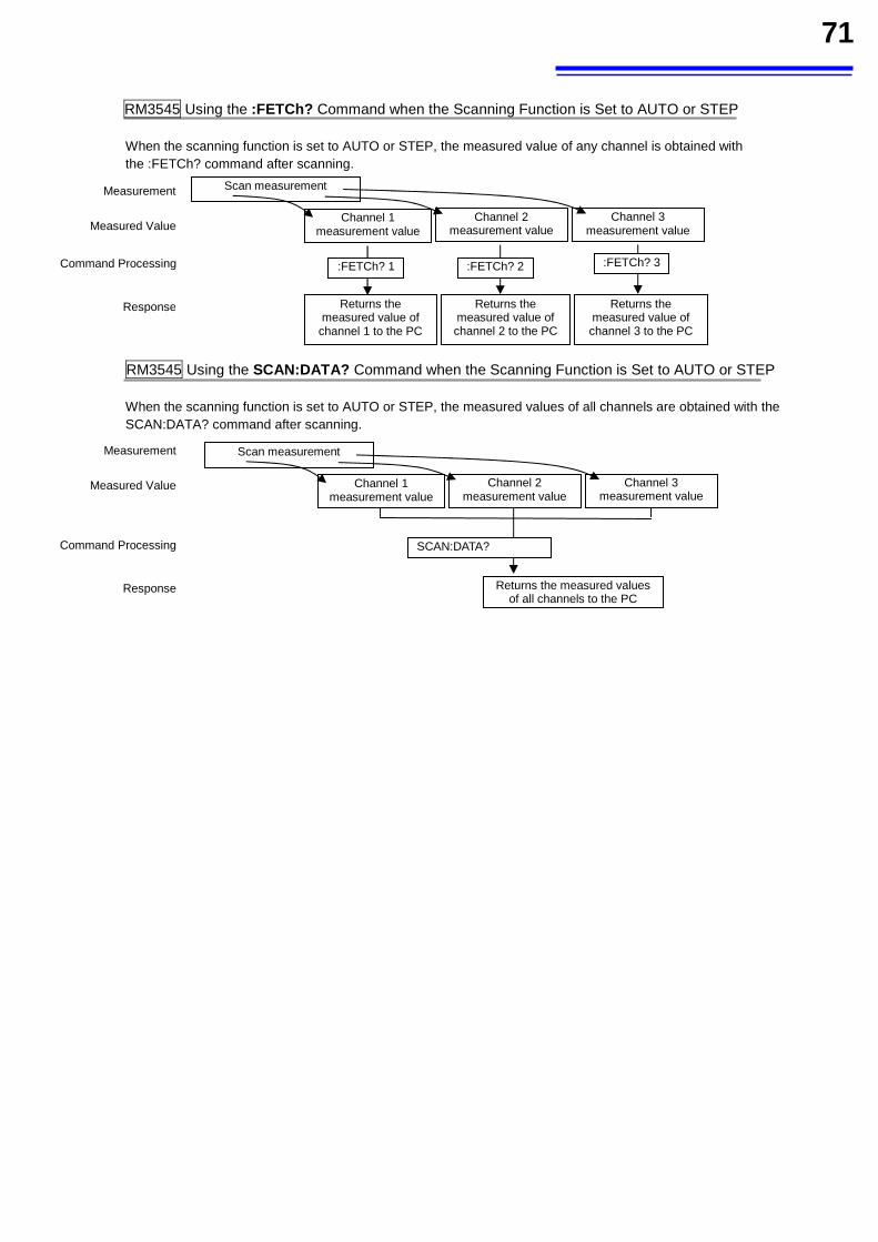
71
RM3545 Using the :FETCh? Command when the Scanning Function is Set to AUTO or STEP
When the scanning function is set to AUTO or STEP, the measured value of any channel is obtained with the :FETCh? command after scanning.
RM3545 Using the SCAN:DATA? Command when the Scanning Function is Set to AUTO or STEP When the scanning function is set to AUTO or STEP, the measured values of all channels are obtained with the SCAN:DATA? command after scanning.
Channel 1 measurement value
Channel 2 measurement value
Channel 3 measurement value
:FETCh? 1 :FETCh? 2 :FETCh? 3
Scan measurement Measurement Processing
Measured Value Update
Response
Command Processing
Returns the measured value of
channel 1 to the PC
Returns the measured value of channel 2 to the PC
Returns the measured value of channel 3 to the PC
SCAN:DATA?
Measurement
Measured Value
Response
Command Processing
Returns the measured values of all channels to the PC
Channel 1 measurement value
Channel 2 measurement value
Channel 3 measurement value
Scan measurement
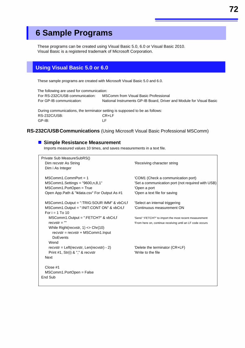
72
6 Sample Programs
These programs can be created using Visual Basic 5.0, 6.0 or Visual Basic 2010. Visual Basic is a registered trademark of Microsoft Corporation.
Using Visual Basic 5.0 or 6.0
These sample programs are created with Microsoft Visual Basic 5.0 and 6.0. The following are used for communication: For RS-232C/USB communication: MSComm from Visual Basic Professional For GP-IB communication: National Instruments GP-IB Board, Driver and Module for Visual Basic During communications, the terminator setting is supposed to be as follows: RS-232C/USB: CR+LF GP-IB: LF
RS-232C/USB Communications (Using Microsoft Visual Basic Professional MSComm)
Simple Resistance Measurement Imports measured values 10 times, and saves measurements in a text file.
Private Sub MeasureSubRS() Dim recvstr As String 'Receiving character string
Dim i As Integer MSComm1.CommPort = 1 'COM1 (Check a communication port) MSComm1.Settings = "9600,n,8,1" 'Set a communication port (not required with USB) MSComm1.PortOpen = True 'Open a port Open App.Path & "¥data.csv" For Output As #1 'Open a text file for saving MSComm1.Output = ":TRIG:SOUR IMM" & vbCrLf 'Select an internal triggering MSComm1.Output = ":INIT:CONT ON" & vbCrLf 'Continuous measurement ON For i = 1 To 10
MSComm1.Output = ":FETCH?" & vbCrLf 'Send “:FETCH?” to import the most recent measurement
recvstr = "" 'From here on, continue receiving until an LF code occurs
While Right(recvstr, 1) <> Chr(10) recvstr = recvstr + MSComm1.Input DoEvents
Wend recvstr = Left(recvstr, Len(recvstr) - 2) 'Delete the terminator (CR+LF) Print #1, Str(i) & "," & recvstr 'Write to the file
Next
Close #1 MSComm1.PortOpen = False
End Sub
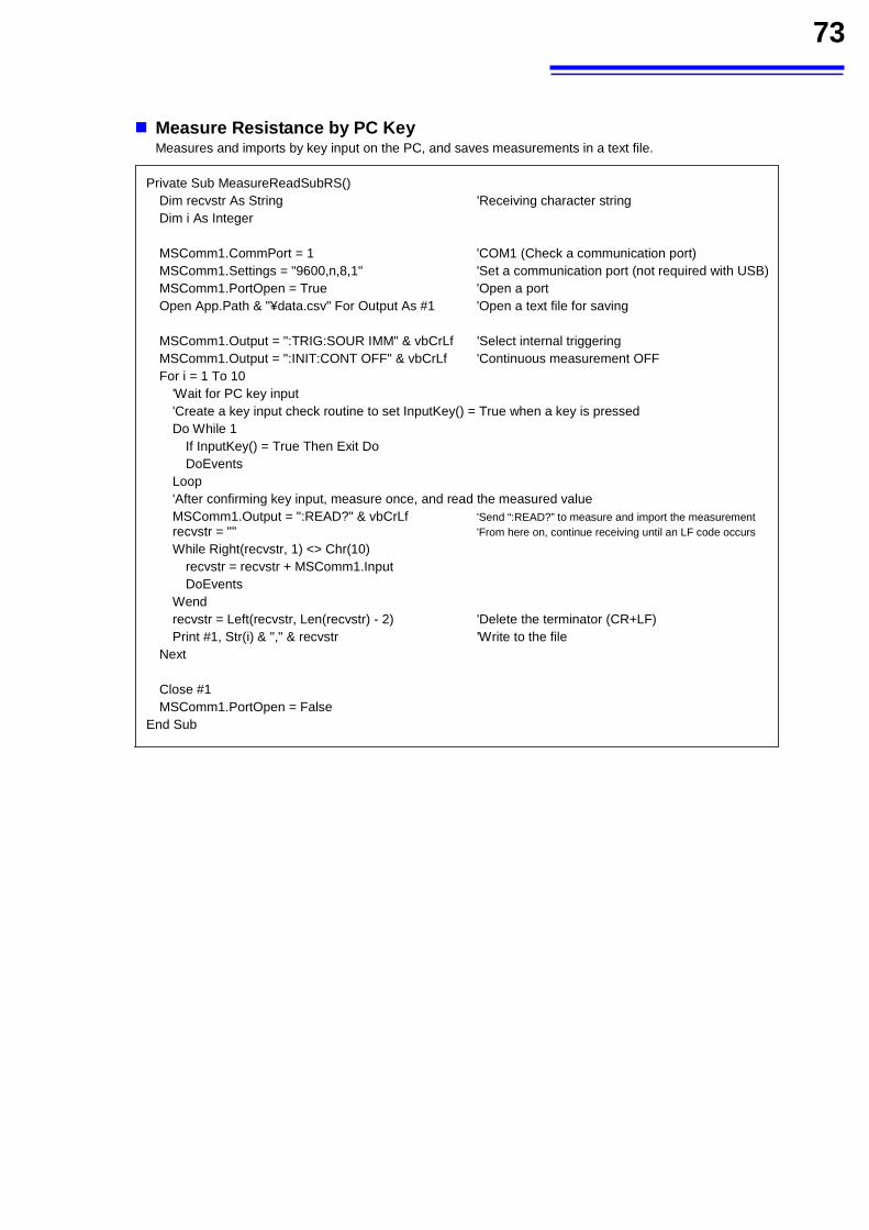
73
Measure Resistance by PC Key Measures and imports by key input on the PC, and saves measurements in a text file.
Private Sub MeasureReadSubRS() Dim recvstr As String 'Receiving character string
Dim i As Integer MSComm1.CommPort = 1 'COM1 (Check a communication port) MSComm1.Settings = "9600,n,8,1" 'Set a communication port (not required with USB) MSComm1.PortOpen = True 'Open a port Open App.Path & "¥data.csv" For Output As #1 'Open a text file for saving MSComm1.Output = ":TRIG:SOUR IMM" & vbCrLf 'Select internal triggering MSComm1.Output = ":INIT:CONT OFF" & vbCrLf 'Continuous measurement OFF For i = 1 To 10
'Wait for PC key input 'Create a key input check routine to set InputKey() = True when a key is pressed
Do While 1 If InputKey() = True Then Exit Do DoEvents
Loop 'After confirming key input, measure once, and read the measured value
MSComm1.Output = ":READ?" & vbCrLf 'Send “:READ?” to measure and import the measurement recvstr = "" 'From here on, continue receiving until an LF code occurs
While Right(recvstr, 1) <> Chr(10) recvstr = recvstr + MSComm1.Input DoEvents
Wend recvstr = Left(recvstr, Len(recvstr) - 2) 'Delete the terminator (CR+LF) Print #1, Str(i) & "," & recvstr 'Write to the file
Next
Close #1 MSComm1.PortOpen = False
End Sub
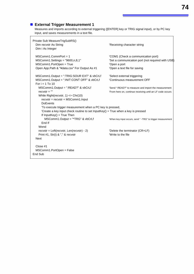
74
External Trigger Measurement 1 Measures and imports according to external triggering ([ENTER] key or TRIG signal input), or by PC key input, and saves measurements in a text file.
Private Sub MeasureTrigSubRS() Dim recvstr As String 'Receiving character string
Dim i As Integer
MSComm1.CommPort = 1 'COM1 (Check a communication port) MSComm1.Settings = "9600,n,8,1" 'Set a communication port (not required with USB) MSComm1.PortOpen = True 'Open a port Open App.Path & "¥data.csv" For Output As #1 'Open a text file for saving
MSComm1.Output = ":TRIG:SOUR EXT" & vbCrLf 'Select external triggering
MSComm1.Output = ":INIT:CONT OFF" & vbCrLf 'Continuous measurement OFF
For i = 1 To 10 MSComm1.Output = ":READ?" & vbCrLf 'Send “:READ?” to measure and import the measurement
recvstr = "" 'From here on, continue receiving until an LF code occurs
While Right(recvstr, 1) <> Chr(10) recvstr = recvstr + MSComm1.Input DoEvents 'To execute trigger measurement when a PC key is pressed, 'Create a key input check routine to set InputKey() = True when a key is pressed
If InputKey() = True Then MSComm1.Output = "*TRG" & vbCrLf 'When key input occurs, send “TRG” to trigger measurement
End If Wend recvstr = Left(recvstr, Len(recvstr) - 2) 'Delete the terminator (CR+LF) Print #1, Str(i) & "," & recvstr 'Write to the file
Next
Close #1 MSComm1.PortOpen = False
End Sub
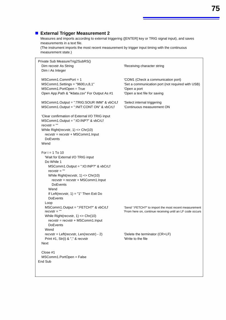
75
External Trigger Measurement 2 Measures and imports according to external triggering ([ENTER] key or TRIG signal input), and saves measurements in a text file. (The instrument imports the most recent measurement by trigger input timing with the continuous measurement state.)
Private Sub MeasureTrig2SubRS() Dim recvstr As String 'Receiving character string
Dim i As Integer
MSComm1.CommPort = 1 'COM1 (Check a communication port) MSComm1.Settings = "9600,n,8,1" 'Set a communication port (not required with USB) MSComm1.PortOpen = True 'Open a port Open App.Path & "¥data.csv" For Output As #1 'Open a text file for saving
MSComm1.Output = ":TRIG:SOUR IMM" & vbCrLf 'Select internal triggering
MSComm1.Output = ":INIT:CONT ON" & vbCrLf 'Continuous measurement ON
'Clear confirmation of External I/O TRIG input MSComm1.Output = ":IO:INP?" & vbCrLf recvstr = "" While Right(recvstr, 1) <> Chr(10)
recvstr = recvstr + MSComm1.Input DoEvents
Wend
For i = 1 To 10 'Wait for External I/O TRIG input Do While 1
MSComm1.Output = ":IO:INP?" & vbCrLf recvstr = "" While Right(recvstr, 1) <> Chr(10)
recvstr = recvstr + MSComm1.Input DoEvents
Wend If Left(recvstr, 1) = "1" Then Exit Do DoEvents
Loop MSComm1.Output = ":FETCH?" & vbCrLf 'Send “:FETCH?” to import the most recent measurement recvstr = "" 'From here on, continue receiving until an LF code occurs
While Right(recvstr, 1) <> Chr(10) recvstr = recvstr + MSComm1.Input DoEvents
Wend recvstr = Left(recvstr, Len(recvstr) - 2) 'Delete the terminator (CR+LF) Print #1, Str(i) & "," & recvstr 'Write to the file
Next
Close #1 MSComm1.PortOpen = False
End Sub
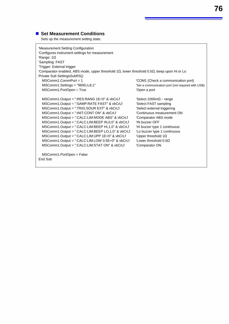
76
Set Measurement Conditions Sets up the measurement setting state.
'Measurement Setting Configuration
'Configures instrument settings for measurement 'Range: 1Ω 'Sampling: FAST
'Trigger: External trigger 'Comparator enabled, ABS mode, upper threshold 1Ω, lower threshold 0.5Ω, beep upon Hi or Lo
Private Sub SettingsSubRS() MSComm1.CommPort = 1 'COM1 (Check a communication port) MSComm1.Settings = "9600,n,8,1" 'Set a communication port (not required with USB)
MSComm1.PortOpen = True 'Open a port MSComm1.Output = ":RES:RANG 1E+0" & vbCrLf 'Select 1000mΩ range MSComm1.Output = ":SAMP:RATE FAST" & vbCrLf 'Select FAST sampling MSComm1.Output = ":TRIG:SOUR EXT" & vbCrLf 'Select external triggering MSComm1.Output = ":INIT:CONT ON" & vbCrLf 'Continuous measurement ON MSComm1.Output = ":CALC:LIM:MODE ABS" & vbCrLf 'Comparator ABS mode MSComm1.Output = ":CALC:LIM:BEEP IN,0,0" & vbCrLf 'IN buzzer OFF MSComm1.Output = ":CALC:LIM:BEEP HI,1,0" & vbCrLf 'Hi buzzer type 1 continuous MSComm1.Output = ":CALC:LIM:BEEP LO,1,0" & vbCrLf 'Lo buzzer type 1 continuous MSComm1.Output = ":CALC:LIM:UPP 1E+0" & vbCrLf 'Upper threshold 1Ω MSComm1.Output = ":CALC:LIM:LOW 0.5E+0" & vbCrLf 'Lower threshold 0.5Ω MSComm1.Output = ":CALC:LIM:STAT ON" & vbCrLf 'Comparator ON
MSComm1.PortOpen = False End Sub
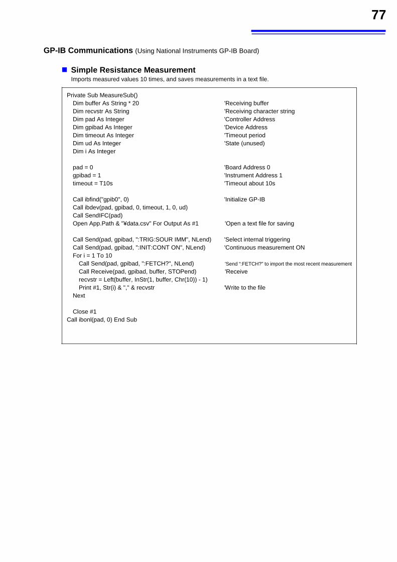
77
GP-IB Communications (Using National Instruments GP-IB Board)
Simple Resistance Measurement Imports measured values 10 times, and saves measurements in a text file.
Private Sub MeasureSub() Dim buffer As String * 20 'Receiving buffer Dim recvstr As String 'Receiving character string
Dim pad As Integer 'Controller Address
Dim gpibad As Integer 'Device Address
Dim timeout As Integer 'Timeout period
Dim ud As Integer 'State (unused) Dim i As Integer
pad = 0 'Board Address 0
gpibad = 1 'Instrument Address 1
timeout = T10s 'Timeout about 10s
Call ibfind("gpib0", 0) 'Initialize GP-IB
Call ibdev(pad, gpibad, 0, timeout, 1, 0, ud) Call SendIFC(pad) Open App.Path & "¥data.csv" For Output As #1 'Open a text file for saving
Call Send(pad, gpibad, ":TRIG:SOUR IMM", NLend) 'Select internal triggering
Call Send(pad, gpibad, ":INIT:CONT ON", NLend) 'Continuous measurement ON
For i = 1 To 10 Call Send(pad, gpibad, ":FETCH?", NLend) 'Send “:FETCH?” to import the most recent measurement
Call Receive(pad, gpibad, buffer, STOPend) 'Receive
recvstr = Left(buffer, InStr(1, buffer, Chr(10)) - 1) Print #1, Str(i) & "," & recvstr 'Write to the file
Next
Close #1 Call ibonl(pad, 0) End Sub
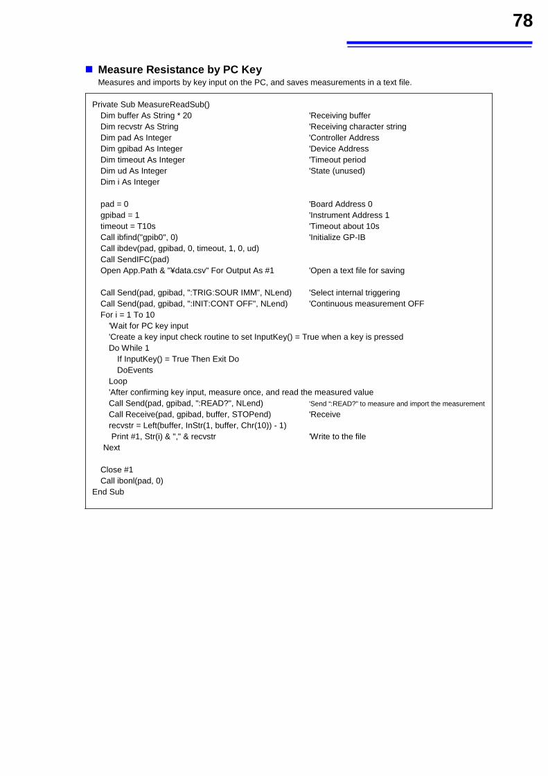
78
Measure Resistance by PC Key Measures and imports by key input on the PC, and saves measurements in a text file.
Private Sub MeasureReadSub() Dim buffer As String * 20 'Receiving buffer Dim recvstr As String 'Receiving character string
Dim pad As Integer 'Controller Address
Dim gpibad As Integer 'Device Address
Dim timeout As Integer 'Timeout period
Dim ud As Integer 'State (unused) Dim i As Integer
pad = 0 'Board Address 0
gpibad = 1 'Instrument Address 1
timeout = T10s 'Timeout about 10s
Call ibfind("gpib0", 0) 'Initialize GP-IB
Call ibdev(pad, gpibad, 0, timeout, 1, 0, ud) Call SendIFC(pad) Open App.Path & "¥data.csv" For Output As #1 'Open a text file for saving
Call Send(pad, gpibad, ":TRIG:SOUR IMM", NLend) 'Select internal triggering
Call Send(pad, gpibad, ":INIT:CONT OFF", NLend) 'Continuous measurement OFF
For i = 1 To 10 'Wait for PC key input 'Create a key input check routine to set InputKey() = True when a key is pressed
Do While 1 If InputKey() = True Then Exit Do DoEvents
Loop 'After confirming key input, measure once, and read the measured value
Call Send(pad, gpibad, ":READ?", NLend) 'Send “:READ?” to measure and import the measurement
Call Receive(pad, gpibad, buffer, STOPend) 'Receive
recvstr = Left(buffer, InStr(1, buffer, Chr(10)) - 1) Print #1, Str(i) & "," & recvstr 'Write to the file
Next
Close #1 Call ibonl(pad, 0)
End Sub
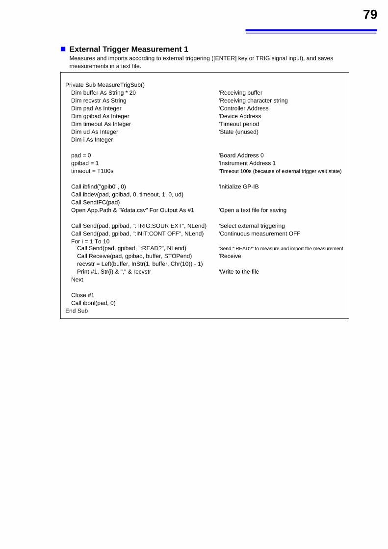
79
External Trigger Measurement 1 Measures and imports according to external triggering ([ENTER] key or TRIG signal input), and saves measurements in a text file.
Private Sub MeasureTrigSub()
Dim buffer As String * 20 'Receiving buffer Dim recvstr As String 'Receiving character string
Dim pad As Integer 'Controller Address
Dim gpibad As Integer 'Device Address
Dim timeout As Integer 'Timeout period
Dim ud As Integer 'State (unused) Dim i As Integer
pad = 0 'Board Address 0
gpibad = 1 'Instrument Address 1
timeout = T100s 'Timeout 100s (because of external trigger wait state)
Call ibfind("gpib0", 0) 'Initialize GP-IB
Call ibdev(pad, gpibad, 0, timeout, 1, 0, ud) Call SendIFC(pad) Open App.Path & "¥data.csv" For Output As #1 'Open a text file for saving
Call Send(pad, gpibad, ":TRIG:SOUR EXT", NLend) 'Select external triggering
Call Send(pad, gpibad, ":INIT:CONT OFF", NLend) 'Continuous measurement OFF
For i = 1 To 10 Call Send(pad, gpibad, ":READ?", NLend) 'Send “:READ?” to measure and import the measurement
Call Receive(pad, gpibad, buffer, STOPend) 'Receive
recvstr = Left(buffer, InStr(1, buffer, Chr(10)) - 1) Print #1, Str(i) & "," & recvstr 'Write to the file
Next
Close #1 Call ibonl(pad, 0)
End Sub
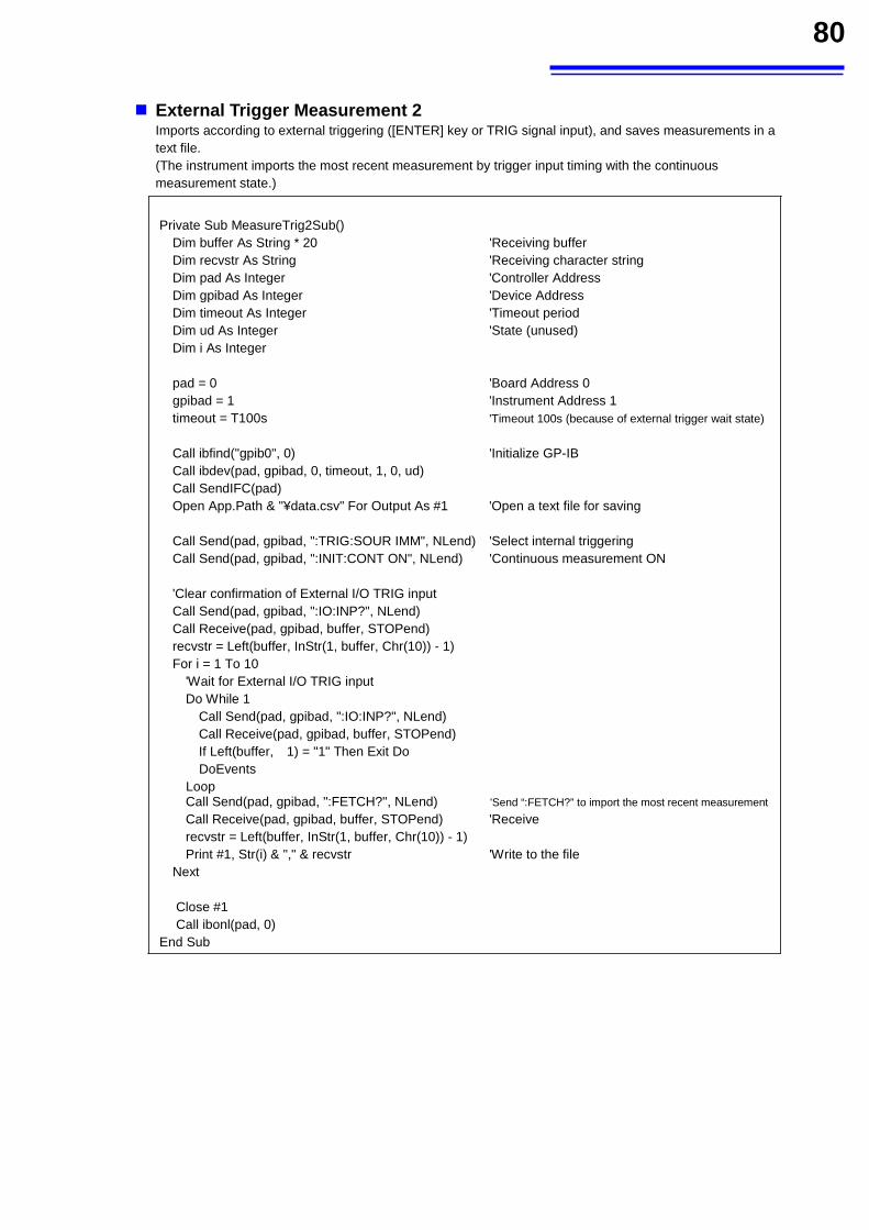
80
External Trigger Measurement 2 Imports according to external triggering ([ENTER] key or TRIG signal input), and saves measurements in a text file. (The instrument imports the most recent measurement by trigger input timing with the continuous measurement state.)
Private Sub MeasureTrig2Sub()
Dim buffer As String * 20 'Receiving buffer Dim recvstr As String 'Receiving character string
Dim pad As Integer 'Controller Address
Dim gpibad As Integer 'Device Address
Dim timeout As Integer 'Timeout period
Dim ud As Integer 'State (unused) Dim i As Integer
pad = 0 'Board Address 0
gpibad = 1 'Instrument Address 1
timeout = T100s 'Timeout 100s (because of external trigger wait state)
Call ibfind("gpib0", 0) 'Initialize GP-IB
Call ibdev(pad, gpibad, 0, timeout, 1, 0, ud) Call SendIFC(pad) Open App.Path & "¥data.csv" For Output As #1 'Open a text file for saving
Call Send(pad, gpibad, ":TRIG:SOUR IMM", NLend) 'Select internal triggering
Call Send(pad, gpibad, ":INIT:CONT ON", NLend) 'Continuous measurement ON
'Clear confirmation of External I/O TRIG input Call Send(pad, gpibad, ":IO:INP?", NLend) Call Receive(pad, gpibad, buffer, STOPend) recvstr = Left(buffer, InStr(1, buffer, Chr(10)) - 1) For i = 1 To 10
'Wait for External I/O TRIG input Do While 1
Call Send(pad, gpibad, ":IO:INP?", NLend) Call Receive(pad, gpibad, buffer, STOPend) If Left(buffer, 1) = "1" Then Exit Do DoEvents
Loop Call Send(pad, gpibad, ":FETCH?", NLend) 'Send “:FETCH?” to import the most recent measurement
Call Receive(pad, gpibad, buffer, STOPend) 'Receive
recvstr = Left(buffer, InStr(1, buffer, Chr(10)) - 1) Print #1, Str(i) & "," & recvstr 'Write to the file
Next
Close #1 Call ibonl(pad, 0)
End Sub
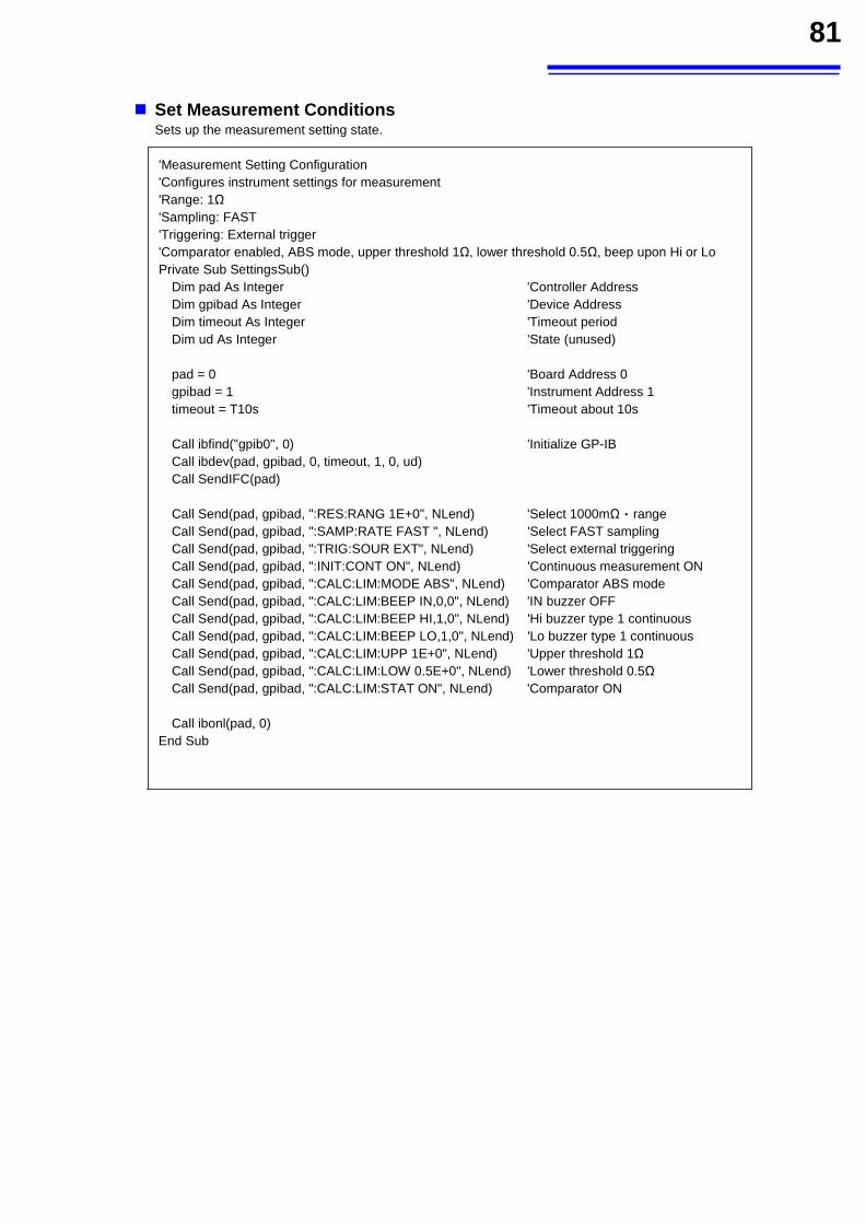
81
Set Measurement Conditions Sets up the measurement setting state.
'Measurement Setting Configuration
'Configures instrument settings for measurement 'Range: 1Ω 'Sampling: FAST
'Triggering: External trigger 'Comparator enabled, ABS mode, upper threshold 1Ω, lower threshold 0.5Ω, beep upon Hi or Lo
Private Sub SettingsSub() Dim pad As Integer 'Controller Address
Dim gpibad As Integer 'Device Address
Dim timeout As Integer 'Timeout period
Dim ud As Integer 'State (unused)
pad = 0 'Board Address 0
gpibad = 1 'Instrument Address 1
timeout = T10s 'Timeout about 10s
Call ibfind("gpib0", 0) 'Initialize GP-IB
Call ibdev(pad, gpibad, 0, timeout, 1, 0, ud) Call SendIFC(pad)
Call Send(pad, gpibad, ":RES:RANG 1E+0", NLend) 'Select 1000mΩ range
Call Send(pad, gpibad, ":SAMP:RATE FAST ", NLend) 'Select FAST sampling
Call Send(pad, gpibad, ":TRIG:SOUR EXT", NLend) 'Select external triggering
Call Send(pad, gpibad, ":INIT:CONT ON", NLend) 'Continuous measurement ON
Call Send(pad, gpibad, ":CALC:LIM:MODE ABS", NLend) 'Comparator ABS mode
Call Send(pad, gpibad, ":CALC:LIM:BEEP IN,0,0", NLend) 'IN buzzer OFF
Call Send(pad, gpibad, ":CALC:LIM:BEEP HI,1,0", NLend) 'Hi buzzer type 1 continuous
Call Send(pad, gpibad, ":CALC:LIM:BEEP LO,1,0", NLend) 'Lo buzzer type 1 continuous
Call Send(pad, gpibad, ":CALC:LIM:UPP 1E+0", NLend) 'Upper threshold 1Ω
Call Send(pad, gpibad, ":CALC:LIM:LOW 0.5E+0", NLend) 'Lower threshold 0.5Ω
Call Send(pad, gpibad, ":CALC:LIM:STAT ON", NLend) 'Comparator ON
Call ibonl(pad, 0) End Sub
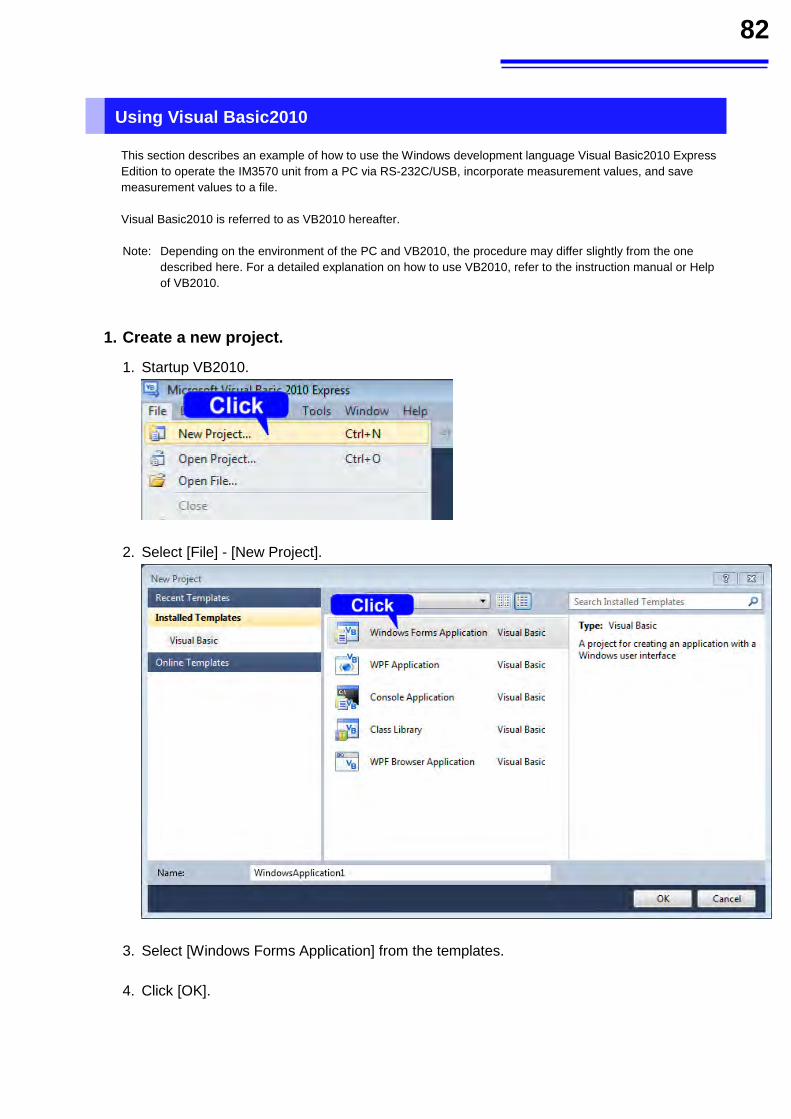
82
Using Visual Basic2010
This section describes an example of how to use the Windows development language Visual Basic2010 Express Edition to operate the IM3570 unit from a PC via RS-232C/USB, incorporate measurement values, and save measurement values to a file. Visual Basic2010 is referred to as VB2010 hereafter. Note: Depending on the environment of the PC and VB2010, the procedure may differ slightly from the one
described here. For a detailed explanation on how to use VB2010, refer to the instruction manual or Help of VB2010.
1. Create a new project.
1. Startup VB2010.
2. Select [File] - [New Project].
3. Select [Windows Forms Application] from the templates. 4. Click [OK].
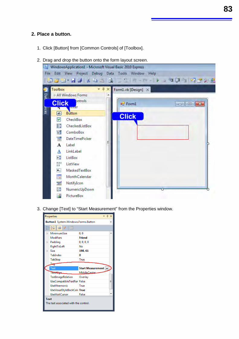
83
2. Place a button.
1. Click [Button] from [Common Controls] of [Toolbox]. 2. Drag and drop the button onto the form layout screen.
3. Change [Text] to “Start Measurement” from the Properties window.
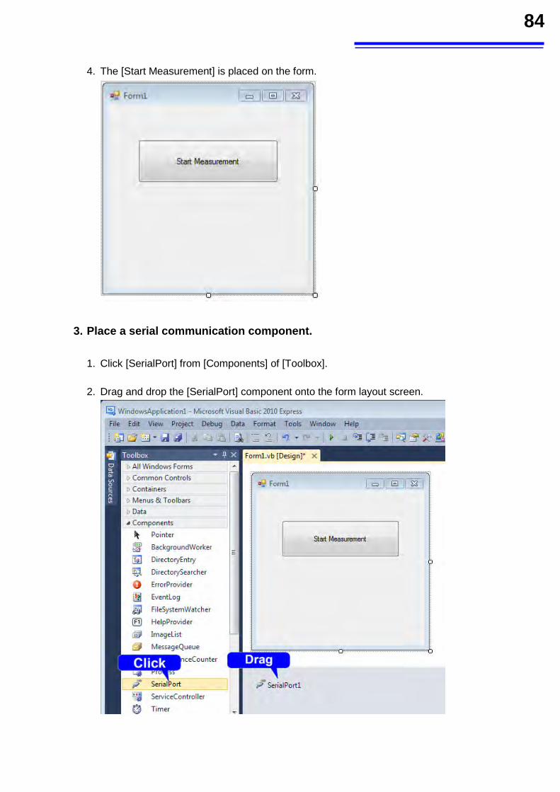
84
4. The [Start Measurement] is placed on the form.
3. Place a serial communication component.
1. Click [SerialPort] from [Components] of [Toolbox]. 2. Drag and drop the [SerialPort] component onto the form layout screen.
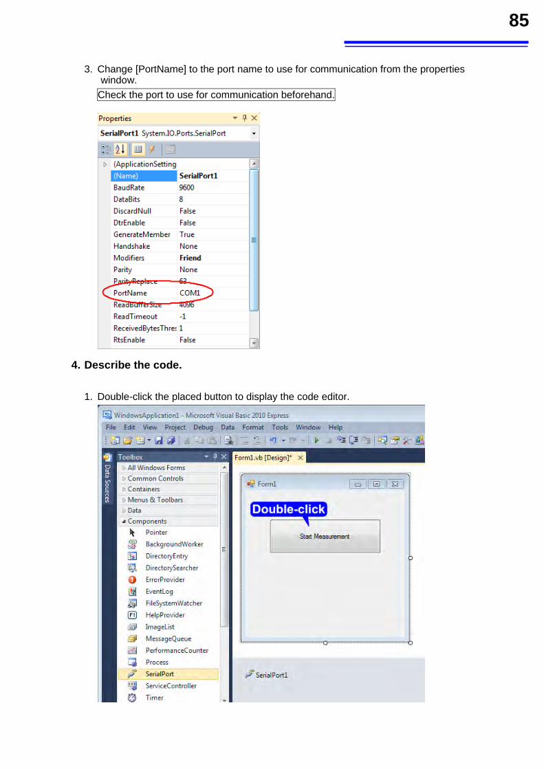
85
3. Change [PortName] to the port name to use for communication from the properties
window.
Check the port to use for communication beforehand.
4. Describe the code.
1. Double-click the placed button to display the code editor.
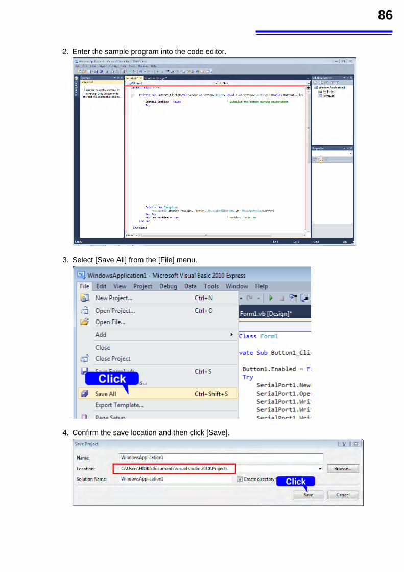
86
2. Enter the sample program into the code editor.
3. Select [Save All] from the [File] menu.
4. Confirm the save location and then click [Save].
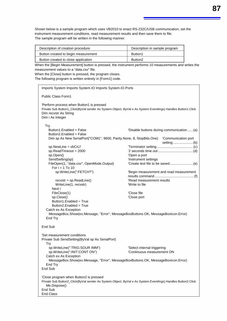
87
Shown below is a sample program which uses VB2010 to enact RS-232C/USB communication, set the instrument measurement conditions, read measurement results and then save them to file. The sample program will be written in the following manner.
Description of creation procedure Description in sample program Button created to begin measurement Button1
Button created to close application Button2 When the [Begin Measurement] button is pressed, the instrument performs 10 measurements and writes the measurement values to a “data.csv” file. When the [Close] button is pressed, the program closes. The following program is written entirely in [Form1] code.
Imports System Imports System.IO Imports System.IO.Ports Public Class Form1 'Perform process when Button1 is pressed Private Sub Button1_Click(ByVal sender As System.Object, ByVal e As System.EventArgs) Handles Button1.Click Dim recvstr As String Dim i As Integer
Try Button1.Enabled = False 'Disable buttons during communication ........ (a) Button2.Enabled = False Dim sp As New SerialPort("COM1", 9600, Parity.None, 8, StopBits.One) 'Communication port
setting ............................. (b) sp.NewLine = vbCrLf 'Terminator setting ..................................................... (c) sp.ReadTimeout = 2000 '2 seconds time out ................................................... (d) sp.Open() 'Open a port SendSetting(sp) 'Instrument settings FileOpen(1, "data.csv", OpenMode.Output) 'Create text file to be saved .................................. (e)
For i = 1 To 10 sp.WriteLine(":FETCH?") 'Begin measurement and read measurement
results command ......................................................... (f) recvstr = sp.ReadLine() 'Read measurement results WriteLine(1, recvstr) 'Write to file
Next i FileClose(1) 'Close file sp.Close() 'Close port Button1.Enabled = True Button2.Enabled = True
Catch ex As Exception MessageBox.Show(ex.Message, "Error", MessageBoxButtons.OK, MessageBoxIcon.Error)
End Try
End Sub 'Set measurement conditions Private Sub SendSetting(ByVal sp As SerialPort)
Try sp.WriteLine(":TRIG:SOUR IMM") 'Select internal triggering sp.WriteLine(":INIT:CONT ON") 'Continuous measurement ON
Catch ex As Exception MessageBox.Show(ex.Message, "Error", MessageBoxButtons.OK, MessageBoxIcon.Error)
End Try End Sub 'Close program when Button2 is pressed Private Sub Button2_Click(ByVal sender As System.Object, ByVal e As System.EventArgs) Handles Button2.Click
Me.Dispose() End Sub End Class
88
(a) During communication the [Begin Measurement] and [Close] buttons cannot be pressed. (b) Matches the instrument communication conditions and the computer usage conditions. The port to be used on the computer: 1 Transmission speed: 9600 bps Parity: none Data length: 8-bit Stop bit: 1-bit (not required with USB) (c) Sets CR + LF as the terminator indicating the end of the sending and receiving character string. (d) Sets the reading operation time to 2 seconds. (e) Opens the “data.csv” file. However, if a file with this name already exists, the previous “data.csv” will be
deleted and a new file created. (f) Sends the command to the instrument to perform one measurement and return that measurement result to
the computer.
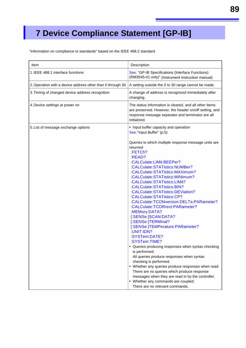
89
7 Device Compliance Statement [GP-IB]
“Information on compliance to standards” based on the IEEE 488.2 standard
Item Description
1. IEEE 488.1 interface functions See: “GP-IB Specifications (Interface Functions) (RM3545-01 only)” (Instrument instruction manual)
2. Operation with a device address other than 0 through 30 A setting outside the 0 to 30 range cannot be made.
3. Timing of changed device address recognition A change of address is recognized immediately after changing.
4. Device settings at power on The status information is cleared, and all other items are preserved. However, the header on/off setting, and response message separator and terminator are all initialized.
5. List of message exchange options • Input buffer capacity and operation See: “Input Buffer” (p.5)
Queries to which multiple response message units are returned :FETCh? :READ? :CALCulate:LIMit:BEEPer? :CALCulate:STATistics:NUMBer? :CALCulate:STATistics:MAXimum? :CALCulate:STATistics:MINimum? :CALCulate:STATistics:LIMit? :CALCulate:STATistics:BIN? :CALCulate:STATistics:DEViation? :CALCulate:STATistics:CP? :CALCulate:TCONversion:DELTa:PARameter? :CALCulate:TCORrect:PARameter? :MEMory:DATA? [:SENSe:]SCAN:DATA? [:SENSe:]TERMinal? [:SENSe:]TEMPerature:PARameter? :UNIT:IDN? :SYSTem:DATE? :SYSTem:TIME?
• Queries producing responses when syntax checking is performed:
All queries produce responses when syntax checking is performed.
• Whether any queries produce responses when read: There are no queries which produce response
messages when they are read in by the controller. • Whether any commands are coupled: There are no relevant commands.
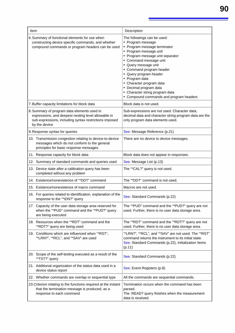
90
Item Description
6. Summary of functional elements for use when constructing device specific commands, and whether compound commands or program headers can be used
The followings can be used: • Program message • Program message terminator • Program message unit • Program message unit separator • Command message unit • Query message unit • Command program header • Query program header • Program data • Character program data • Decimal program data • Character string program data • Compound commands and program headers
7. Buffer capacity limitations for block data Block data is not used.
8. Summary of program data elements used in expressions, and deepest nesting level allowable in sub-expressions, including syntax restrictions imposed by the device
Sub-expressions are not used. Character data, decimal data and character string program data are the only program data elements used.
9. Response syntax for queries See: Message Reference (p.21)
10. Transmission congestion relating to device-to-device messages which do not conform to the general principles for basic response messages
There are no device to device messages.
11. Response capacity for block data Block data does not appear in responses.
12. Summary of standard commands and queries used See: Message List (p.13)
13. Device state after a calibration query has been completed without any problem
The “*CAL?” query is not used.
14. Existence/nonexistence of “*DDT” command The “*DDT” command is not used.
15. Existence/nonexistence of macro command Macros are not used.
16. For queries related to identification, explanation of the response to the “*IDN?” query
See: Standard Commands (p.22)
17. Capacity of the user data storage area reserved for when the “*PUD” command and the “*PUD?” query are being executed
The “*PUD” command and the “*PUD?” query are not used. Further, there is no user data storage area.
18. Resources when the “*RDT” command and the “*RDT?” query are being used
The “*RDT” command and the “*RDT?” query are not used. Further, there is no user data storage area.
19. Conditions which are influenced when “*RST”, “*LRN?”, “*RCL”, and “*SAV” are used
“*LRN?”, “*RCL”, and “*SAV” are not used. The “*RST” command returns the instrument to its initial state. See: Standard Commands (p.22), Initialization Items (p.11)
20. Scope of the self-testing executed as a result of the “*TST?” query
See: Standard Commands (p.22)
21. Additional organization of the status data used in a device status report
See: Event Registers (p.8)
22. Whether commands are overlap or sequential type All the commands are sequential commands.
23.Criterion relating to the functions required at the instant that the termination message is produced, as a response to each command
Termination occurs when the command has been parsed. The :READ? query finishes when the measurement data is received.