Embed Size (px)
Citation preview
L
Ä.UG*ä
1352
3809
Controller-basedAutomation
Automation Systems
PROFINET® _ _ _ _ _ _ _ _ _ _ _ _ _ _ _ _ _ _ _ _ _ _ _ _ _ _ _ _ _ _ _ _ Communication Manual EN

2 Lenze · Controller-based Automation · PROFINET® Communication Manual · DMS 1.6 EN · 11/2016 · TD17
_ _ _ _ _ _ _ _ _ _ _ _ _ _ _ _ _ _ _ _ _ _ _ _ _ _ _ _ _ _ _ _ _ _ _ _ _ _ _ _ _ _ _ _ _ _ _ _ _ _ _ _ _ _ _ _ _ _ _ _ _ _ _ _
1 About this documentation _ _ _ _ _ _ _ _ _ _ _ _ _ _ _ _ _ _ _ _ _ _ _ _ _ _ _ _ _ _ _ _ _ _ _ _ _ _ _ 31.1 Document history _ _ _ _ _ _ _ _ _ _ _ _ _ _ _ _ _ _ _ _ _ _ _ _ _ _ _ _ _ _ _ _ _ _ _ _ _ _ _ _ _ _ _ _ 51.2 Conventions used _ _ _ _ _ _ _ _ _ _ _ _ _ _ _ _ _ _ _ _ _ _ _ _ _ _ _ _ _ _ _ _ _ _ _ _ _ _ _ _ _ _ _ _ 61.3 Terminology used _ _ _ _ _ _ _ _ _ _ _ _ _ _ _ _ _ _ _ _ _ _ _ _ _ _ _ _ _ _ _ _ _ _ _ _ _ _ _ _ _ _ _ _ 71.4 Definition of the notes used _ _ _ _ _ _ _ _ _ _ _ _ _ _ _ _ _ _ _ _ _ _ _ _ _ _ _ _ _ _ _ _ _ _ _ _ _ _ 9
2 Safety instructions _ _ _ _ _ _ _ _ _ _ _ _ _ _ _ _ _ _ _ _ _ _ _ _ _ _ _ _ _ _ _ _ _ _ _ _ _ _ _ _ _ _ _ _ 10
3 Controller-based Automation: Central motion control _ _ _ _ _ _ _ _ _ _ _ _ _ _ _ _ _ _ _ _ _ _ _ _ 12
4 The Lenze automation system with PROFINET _ _ _ _ _ _ _ _ _ _ _ _ _ _ _ _ _ _ _ _ _ _ _ _ _ _ _ _ _ 154.1 Structure of the PROFINET system _ _ _ _ _ _ _ _ _ _ _ _ _ _ _ _ _ _ _ _ _ _ _ _ _ _ _ _ _ _ _ _ _ _ _ 164.2 Network topology _ _ _ _ _ _ _ _ _ _ _ _ _ _ _ _ _ _ _ _ _ _ _ _ _ _ _ _ _ _ _ _ _ _ _ _ _ _ _ _ _ _ _ _ 174.3 Field devices _ _ _ _ _ _ _ _ _ _ _ _ _ _ _ _ _ _ _ _ _ _ _ _ _ _ _ _ _ _ _ _ _ _ _ _ _ _ _ _ _ _ _ _ _ _ _ 184.4 PROFINET hardware for Lenze Controllers _ _ _ _ _ _ _ _ _ _ _ _ _ _ _ _ _ _ _ _ _ _ _ _ _ _ _ _ _ _ _ 194.5 Lenze Engineering tools _ _ _ _ _ _ _ _ _ _ _ _ _ _ _ _ _ _ _ _ _ _ _ _ _ _ _ _ _ _ _ _ _ _ _ _ _ _ _ _ _ 20
5 Technical data _ _ _ _ _ _ _ _ _ _ _ _ _ _ _ _ _ _ _ _ _ _ _ _ _ _ _ _ _ _ _ _ _ _ _ _ _ _ _ _ _ _ _ _ _ _ 215.1 Technical data of the MC-PND communication card _ _ _ _ _ _ _ _ _ _ _ _ _ _ _ _ _ _ _ _ _ _ _ _ _ 215.2 PROFINET connection _ _ _ _ _ _ _ _ _ _ _ _ _ _ _ _ _ _ _ _ _ _ _ _ _ _ _ _ _ _ _ _ _ _ _ _ _ _ _ _ _ _ 22
6 Commissioning of the PROFINET _ _ _ _ _ _ _ _ _ _ _ _ _ _ _ _ _ _ _ _ _ _ _ _ _ _ _ _ _ _ _ _ _ _ _ _ 236.1 Overview of the commissioning steps _ _ _ _ _ _ _ _ _ _ _ _ _ _ _ _ _ _ _ _ _ _ _ _ _ _ _ _ _ _ _ _ _ 236.2 The commissioning steps in detail _ _ _ _ _ _ _ _ _ _ _ _ _ _ _ _ _ _ _ _ _ _ _ _ _ _ _ _ _ _ _ _ _ _ _ 24
6.2.1 Planning the bus topology _ _ _ _ _ _ _ _ _ _ _ _ _ _ _ _ _ _ _ _ _ _ _ _ _ _ _ _ _ _ _ _ _ _ _ 246.2.2 Installing field devices _ _ _ _ _ _ _ _ _ _ _ _ _ _ _ _ _ _ _ _ _ _ _ _ _ _ _ _ _ _ _ _ _ _ _ _ _ 246.2.3 Create a project folder _ _ _ _ _ _ _ _ _ _ _ _ _ _ _ _ _ _ _ _ _ _ _ _ _ _ _ _ _ _ _ _ _ _ _ _ _ 256.2.4 Commission the field devices _ _ _ _ _ _ _ _ _ _ _ _ _ _ _ _ _ _ _ _ _ _ _ _ _ _ _ _ _ _ _ _ _ 256.2.5 Importing missing devices / device description files _ _ _ _ _ _ _ _ _ _ _ _ _ _ _ _ _ _ _ _ _ 266.2.6 Creating a PLC program with a target system (Logic) _ _ _ _ _ _ _ _ _ _ _ _ _ _ _ _ _ _ _ _ 276.2.7 Configuring the communication parameters _ _ _ _ _ _ _ _ _ _ _ _ _ _ _ _ _ _ _ _ _ _ _ _ 296.2.8 Creating a control configuration (adding field devices) _ _ _ _ _ _ _ _ _ _ _ _ _ _ _ _ _ _ _ 316.2.9 Configuring the I/O device _ _ _ _ _ _ _ _ _ _ _ _ _ _ _ _ _ _ _ _ _ _ _ _ _ _ _ _ _ _ _ _ _ _ 346.2.10 Logging in on the controller with the »PLC Designer« _ _ _ _ _ _ _ _ _ _ _ _ _ _ _ _ _ _ _ _ 34
7 Mixed operation PROFINET with EtherCAT _ _ _ _ _ _ _ _ _ _ _ _ _ _ _ _ _ _ _ _ _ _ _ _ _ _ _ _ _ _ _ 35
8 Defining the cycle time of the PLC project _ _ _ _ _ _ _ _ _ _ _ _ _ _ _ _ _ _ _ _ _ _ _ _ _ _ _ _ _ _ _ 368.1 Determining the task utilisation of the application _ _ _ _ _ _ _ _ _ _ _ _ _ _ _ _ _ _ _ _ _ _ _ _ _ _ 368.2 Optimising the system _ _ _ _ _ _ _ _ _ _ _ _ _ _ _ _ _ _ _ _ _ _ _ _ _ _ _ _ _ _ _ _ _ _ _ _ _ _ _ _ _ 38
9 Diagnostics _ _ _ _ _ _ _ _ _ _ _ _ _ _ _ _ _ _ _ _ _ _ _ _ _ _ _ _ _ _ _ _ _ _ _ _ _ _ _ _ _ _ _ _ _ _ _ _ 399.1 LED status displays of the MC-PND communication card _ _ _ _ _ _ _ _ _ _ _ _ _ _ _ _ _ _ _ _ _ _ _ 409.2 Diagnostics in the »PLC Designer« _ _ _ _ _ _ _ _ _ _ _ _ _ _ _ _ _ _ _ _ _ _ _ _ _ _ _ _ _ _ _ _ _ _ _ 41
10 Parameter reference _ _ _ _ _ _ _ _ _ _ _ _ _ _ _ _ _ _ _ _ _ _ _ _ _ _ _ _ _ _ _ _ _ _ _ _ _ _ _ _ _ _ _ 42
Index _ _ _ _ _ _ _ _ _ _ _ _ _ _ _ _ _ _ _ _ _ _ _ _ _ _ _ _ _ _ _ _ _ _ _ _ _ _ _ _ _ _ _ _ _ _ _ _ _ _ _ 44
Your opinion is important to us _ _ _ _ _ _ _ _ _ _ _ _ _ _ _ _ _ _ _ _ _ _ _ _ _ _ _ _ _ _ _ _ _ _ _ _ _ 46
Contents
Lenze · Controller-based Automation · PROFINET® Communication Manual · DMS 1.6 EN · 11/2016 · TD17 3
1 About this documentation
_ _ _ _ _ _ _ _ _ _ _ _ _ _ _ _ _ _ _ _ _ _ _ _ _ _ _ _ _ _ _ _ _ _ _ _ _ _ _ _ _ _ _ _ _ _ _ _ _ _ _ _ _ _ _ _ _ _ _ _ _ _ _ _
1 About this documentation
This documentation ...
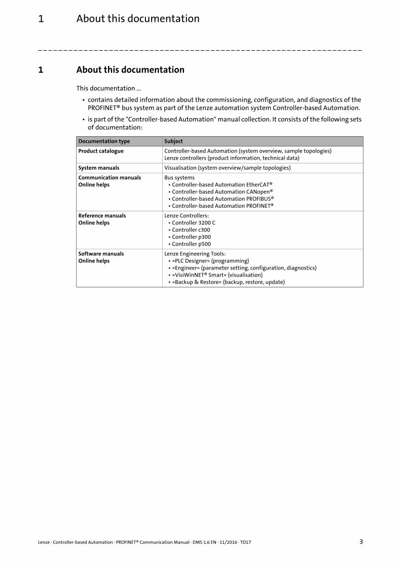
• contains detailed information about the commissioning, configuration, and diagnostics of the PROFINET® bus system as part of the Lenze automation system Controller-based Automation.
• is part of the "Controller-based Automation" manual collection. It consists of the following sets of documentation:
Documentation type Subject
Product catalogue Controller-based Automation (system overview, sample topologies)Lenze controllers (product information, technical data)
System manuals Visualisation (system overview/sample topologies)
Communication manualsOnline helps
Bus systems• Controller-based Automation EtherCAT®• Controller-based Automation CANopen®• Controller-based Automation PROFIBUS®• Controller-based Automation PROFINET®
Reference manualsOnline helps
Lenze Controllers:• Controller 3200 C• Controller c300• Controller p300• Controller p500
Software manualsOnline helps
Lenze Engineering Tools:• »PLC Designer« (programming)• »Engineer« (parameter setting, configuration, diagnostics)• »VisiWinNET® Smart« (visualisation)• »Backup & Restore« (backup, restore, update)
1 About this documentation
4 Lenze · Controller-based Automation · PROFINET® Communication Manual · DMS 1.6 EN · 11/2016 · TD17
_ _ _ _ _ _ _ _ _ _ _ _ _ _ _ _ _ _ _ _ _ _ _ _ _ _ _ _ _ _ _ _ _ _ _ _ _ _ _ _ _ _ _ _ _ _ _ _ _ _ _ _ _ _ _ _ _ _ _ _ _ _ _ _
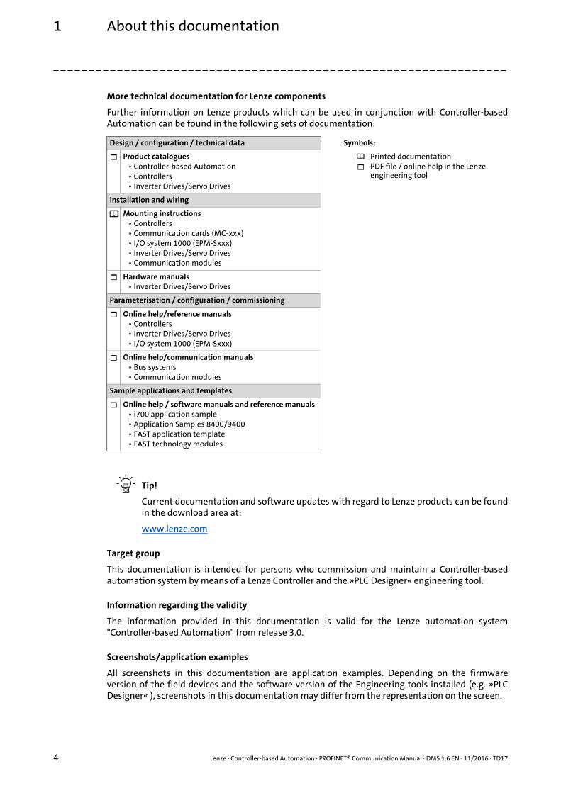
More technical documentation for Lenze components
Further information on Lenze products which can be used in conjunction with Controller-basedAutomation can be found in the following sets of documentation:
Tip!
Current documentation and software updates with regard to Lenze products can be foundin the download area at:
www.lenze.com
Target group
This documentation is intended for persons who commission and maintain a Controller-basedautomation system by means of a Lenze Controller and the »PLC Designer« engineering tool.
Information regarding the validity
The information provided in this documentation is valid for the Lenze automation system"Controller-based Automation" from release 3.0.
Screenshots/application examples
All screenshots in this documentation are application examples. Depending on the firmwareversion of the field devices and the software version of the Engineering tools installed (e.g. »PLCDesigner« ), screenshots in this documentation may differ from the representation on the screen.
Design / configuration / technical data Symbols:
Product catalogues• Controller-based Automation• Controllers• Inverter Drives/Servo Drives
Printed documentationPDF file / online help in the Lenze engineering tool
Installation and wiring
Mounting instructions• Controllers• Communication cards (MC-xxx)• I/O system 1000 (EPM-Sxxx)• Inverter Drives/Servo Drives• Communication modules
Hardware manuals• Inverter Drives/Servo Drives
Parameterisation / configuration / commissioning
Online help/reference manuals• Controllers• Inverter Drives/Servo Drives• I/O system 1000 (EPM-Sxxx)
Online help/communication manuals• Bus systems• Communication modules
Sample applications and templates
Online help / software manuals and reference manuals• i700 application sample• Application Samples 8400/9400• FAST application template• FAST technology modules
Lenze · Controller-based Automation · PROFINET® Communication Manual · DMS 1.6 EN · 11/2016 · TD17 5
1 About this documentation1.1 Document history
_ _ _ _ _ _ _ _ _ _ _ _ _ _ _ _ _ _ _ _ _ _ _ _ _ _ _ _ _ _ _ _ _ _ _ _ _ _ _ _ _ _ _ _ _ _ _ _ _ _ _ _ _ _ _ _ _ _ _ _ _ _ _ _
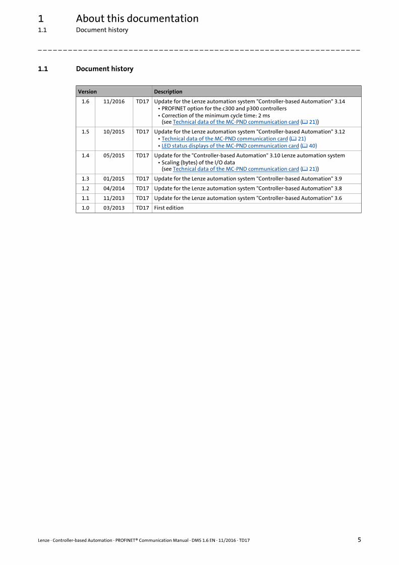
1.1 Document history
Version Description
1.6 11/2016 TD17 Update for the Lenze automation system "Controller-based Automation" 3.14• PROFINET option for the c300 and p300 controllers• Correction of the minimum cycle time: 2 ms
(see Technical data of the MC-PND communication card ( 21))
1.5 10/2015 TD17 Update for the Lenze automation system "Controller-based Automation" 3.12• Technical data of the MC-PND communication card ( 21)• LED status displays of the MC-PND communication card ( 40)
1.4 05/2015 TD17 Update for the "Controller-based Automation" 3.10 Lenze automation system• Scaling (bytes) of the I/O data
(see Technical data of the MC-PND communication card ( 21))
1.3 01/2015 TD17 Update for the Lenze automation system "Controller-based Automation" 3.9
1.2 04/2014 TD17 Update for the Lenze automation system "Controller-based Automation" 3.8
1.1 11/2013 TD17 Update for the Lenze automation system "Controller-based Automation" 3.6
1.0 03/2013 TD17 First edition

1 About this documentation1.2 Conventions used
6 Lenze · Controller-based Automation · PROFINET® Communication Manual · DMS 1.6 EN · 11/2016 · TD17
_ _ _ _ _ _ _ _ _ _ _ _ _ _ _ _ _ _ _ _ _ _ _ _ _ _ _ _ _ _ _ _ _ _ _ _ _ _ _ _ _ _ _ _ _ _ _ _ _ _ _ _ _ _ _ _ _ _ _ _ _ _ _ _
1.2 Conventions used
This documentation uses the following conventions to distinguish between different types ofinformation:
Type of information Highlighting Examples/notes
Spelling of numbers
Decimal Normal spelling Example: 1234
Decimal separator Point The decimal point is always used.For example: 1234.56
Hexadecimal 0x[0 ... 9, A ... F] Example: 0x60F4
Binary• Nibble
0b[0, 1] Example: '0b0110'Example: '0b0110.0100'
Text
Program name » « PC softwareExample: Lenze »Engineer«
Window italics The message window... / The Options dialog box ...
Variable names Setting bEnable to TRUE...
Control element bold The OK button ... / The Copy command ... / The Properties tab ... / The Name input field ...
Sequence of menu commands
If several successive commands are required for executing a function, the individual commands are separated from each other by an arrow: Select the command File Open to...
Shortcut <bold> Use <F1> to open the online help.
If a key combination is required for a command, a "+" is placed between the key identifiers: With <Shift>+<ESC>...
Program code Courier IF var1 < var2 THEN a = a + 1 END IF
Keyword Courier bold
Hyperlink underlined Optically highlighted reference to another topic. Can be activated with a mouse-click in this documentation.
Icons
Page reference ( 6) Optically highlighted reference to another page. Can be activated with a mouse-click in this documentation.
Step-by-step instructions Step-by-step instructions are indicated by a pictograph.

Lenze · Controller-based Automation · PROFINET® Communication Manual · DMS 1.6 EN · 11/2016 · TD17 7
1 About this documentation1.3 Terminology used
_ _ _ _ _ _ _ _ _ _ _ _ _ _ _ _ _ _ _ _ _ _ _ _ _ _ _ _ _ _ _ _ _ _ _ _ _ _ _ _ _ _ _ _ _ _ _ _ _ _ _ _ _ _ _ _ _ _ _ _ _ _ _ _
1.3 Terminology used
Term Meaning
CL-RPC Connectionless Remote Procedure Call
Code Parameter for parameterising or monitoring the field device. The term is also referred to as "index" in common usage.
Controllers The Controller is the central component of the Lenze automation system which control the motion sequences by means of the application software.The Controller communicates with the field devices (inverters) via the fieldbus.
Engineering PC The Engineering PC and the Engineering tools installed serve to configure and parameterise the system "Controller-based Automation".The Engineering PC communicates with the controller via Ethernet.
Engineering tools Software solutions for easy engineering in all phases which serve to commission, configure, parameterise and diagnose the Lenze automation system.Lenze Engineering tools ( 20)
Siemens software for programming and configuring Siemens SIMATIC S7 PLC:• »STEP7«
FAST By default, the Lenze FAST application software is installed on the Lenze Controller in the "FAST runtime" version with "FAST Motion" for the central control of PLC applications.
Fieldbus node Devices integrated in the bus system as, for instance, Controller and inverter
Field device
GSDML file A GSDML file described the properties of a field device.It is described with the XML-based language GSDML (General Station Description Markup Language).
I/O device PROFINET slave
I/O master PROFINET masterThe I/O master takes over the master function for data communication of the decentralised field devices. The I/O master is usually the communication interface of a PLC.
Inverters Generic term for Lenze frequency inverters, servo inverters
PDO Process Data Object
PLC Programmable Logic Controller
RT over UDP Real Time over User Datagram Protocol
PLC Programmable Logic Controller (PLC)
Subcode If a code contains several parameters, they are stored in "subcodes".In the documentation, the slash "/" is used as a separator between the code and the subcode (e.g. "C00118/3").In everyday language, the term is also referred to as "subindex".
Bus systems
CAN CAN (Controller Area Network) is an asynchronous, serial fieldbus system.
CANopen® is a communication protocol based on CAN. The Lenze system bus (CAN on board) operates with a subset of this communication protocol.CANopen® is a registered community trademark of the CAN user organisation CiA® (CAN in Automation e. V.).
EtherCAT® (Ethernet for Controller and Automation Technology) is an Ethernet-based fieldbus system which fulfils the application profile for industrial real-time systems.EtherCAT® is a registered trademark and patented technology, licenced by Beckhoff Automation GmbH, Germany.
Ethernet specifies the software (protocols) and hardware (cables, plugs, etc.) for wired data networks. In the form of "Industrial Ethernet", the Ethernet standard is used in industrial production systems.On the basis of IEEE 802.3, standard Ethernet is specified by the Institute of Electrical and Electronics Engineers (IEEE), USA.

1 About this documentation1.3 Terminology used
8 Lenze · Controller-based Automation · PROFINET® Communication Manual · DMS 1.6 EN · 11/2016 · TD17
_ _ _ _ _ _ _ _ _ _ _ _ _ _ _ _ _ _ _ _ _ _ _ _ _ _ _ _ _ _ _ _ _ _ _ _ _ _ _ _ _ _ _ _ _ _ _ _ _ _ _ _ _ _ _ _ _ _ _ _ _ _ _ _
EtherNet/IP™ (EtherNet Industrial Protocol) is an Ethernet-based fieldbus system that uses Common Industrial Protocol™ (CIP™) to exchange data.EtherNet/IP™ and Common Industrial Protocol™ (CIP™) are brand labels and patented technologies, licensed by the ODVA user organisation (Open DeviceNet Vendor Association), USA.
PROFIBUS® (Process Field Bus) is a widely used fieldbus system for the automation of machines and production lines.PROFIBUS® is a registered trademark and patented technology licensed by the PROFIBUS & PROFINET International (PI) user organisation.
PROFINET® (Process Field Network) is a real-time capable fieldbus system based on Ethernet.PROFINET® is a registered trademark and patented technology licensed by the PROFIBUS & PROFINET International user organisation (PI).
Term Meaning
Lenze · Controller-based Automation · PROFINET® Communication Manual · DMS 1.6 EN · 11/2016 · TD17 9
1 About this documentation1.4 Definition of the notes used
_ _ _ _ _ _ _ _ _ _ _ _ _ _ _ _ _ _ _ _ _ _ _ _ _ _ _ _ _ _ _ _ _ _ _ _ _ _ _ _ _ _ _ _ _ _ _ _ _ _ _ _ _ _ _ _ _ _ _ _ _ _ _ _
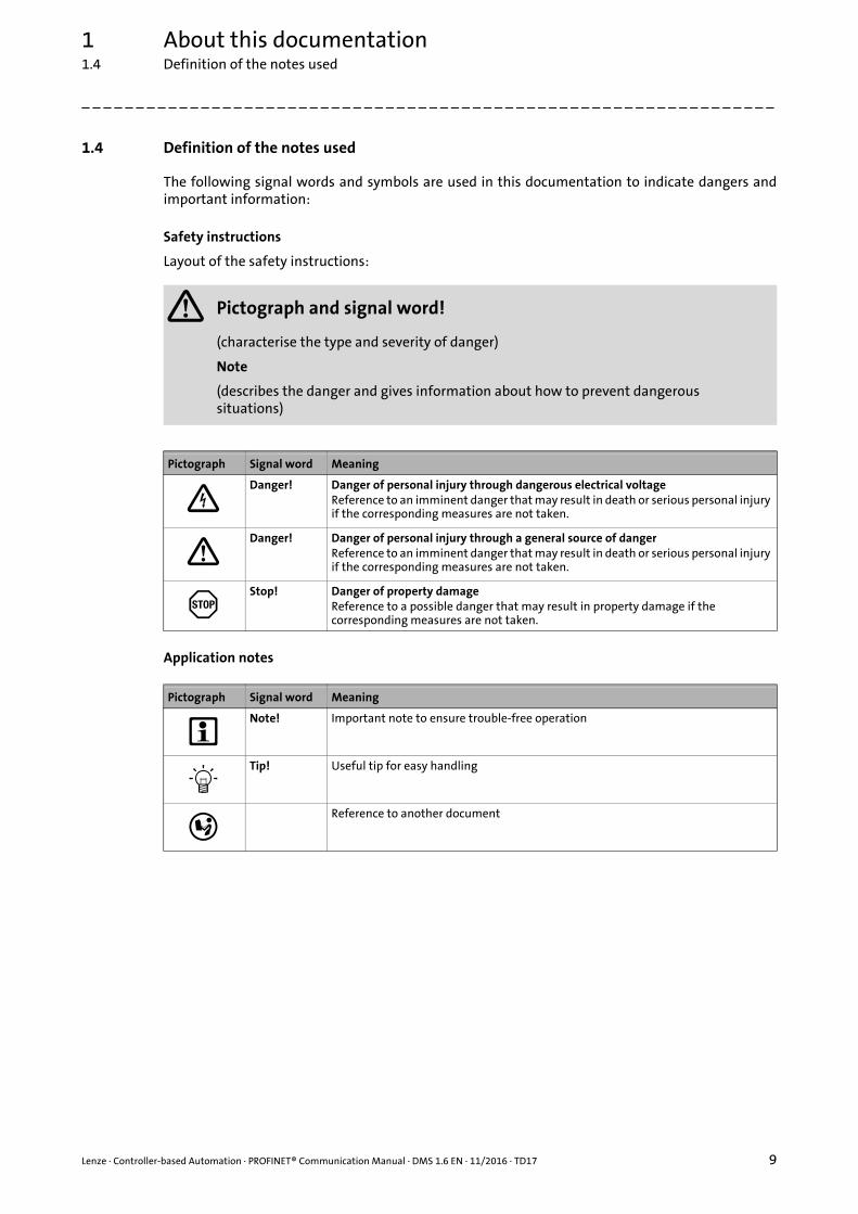
1.4 Definition of the notes used
The following signal words and symbols are used in this documentation to indicate dangers andimportant information:
Safety instructions
Layout of the safety instructions:
Application notes
Pictograph and signal word!
(characterise the type and severity of danger)
Note
(describes the danger and gives information about how to prevent dangerous situations)
Pictograph Signal word Meaning
Danger! Danger of personal injury through dangerous electrical voltageReference to an imminent danger that may result in death or serious personal injury if the corresponding measures are not taken.
Danger! Danger of personal injury through a general source of dangerReference to an imminent danger that may result in death or serious personal injury if the corresponding measures are not taken.
Stop! Danger of property damageReference to a possible danger that may result in property damage if the corresponding measures are not taken.
Pictograph Signal word Meaning
Note! Important note to ensure trouble-free operation
Tip! Useful tip for easy handling
Reference to another document
2 Safety instructions
10 Lenze · Controller-based Automation · PROFINET® Communication Manual · DMS 1.6 EN · 11/2016 · TD17
_ _ _ _ _ _ _ _ _ _ _ _ _ _ _ _ _ _ _ _ _ _ _ _ _ _ _ _ _ _ _ _ _ _ _ _ _ _ _ _ _ _ _ _ _ _ _ _ _ _ _ _ _ _ _ _ _ _ _ _ _ _ _ _
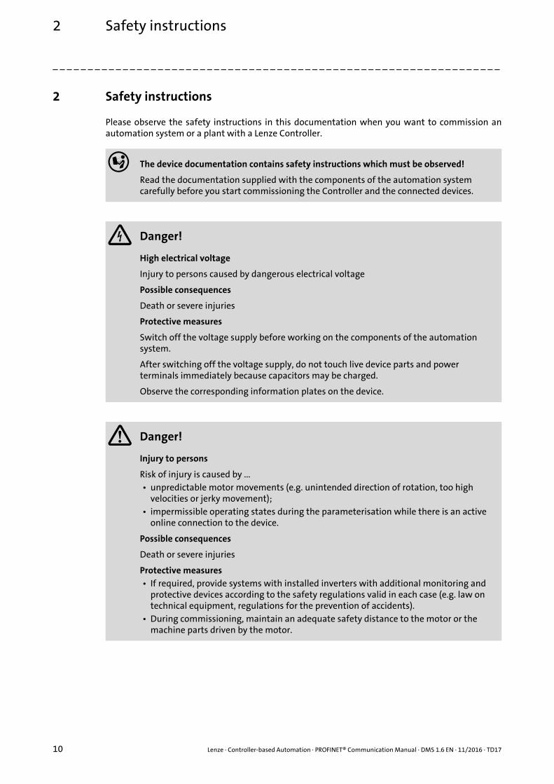
2 Safety instructions
Please observe the safety instructions in this documentation when you want to commission anautomation system or a plant with a Lenze Controller.
The device documentation contains safety instructions which must be observed!
Read the documentation supplied with the components of the automation system carefully before you start commissioning the Controller and the connected devices.
Danger!
High electrical voltage
Injury to persons caused by dangerous electrical voltage
Possible consequences
Death or severe injuries
Protective measures
Switch off the voltage supply before working on the components of the automation system.
After switching off the voltage supply, do not touch live device parts and power terminals immediately because capacitors may be charged.
Observe the corresponding information plates on the device.
Danger!
Injury to persons
Risk of injury is caused by ...• unpredictable motor movements (e.g. unintended direction of rotation, too high
velocities or jerky movement);• impermissible operating states during the parameterisation while there is an active
online connection to the device.
Possible consequences
Death or severe injuries
Protective measures• If required, provide systems with installed inverters with additional monitoring and
protective devices according to the safety regulations valid in each case (e.g. law on technical equipment, regulations for the prevention of accidents).
• During commissioning, maintain an adequate safety distance to the motor or the machine parts driven by the motor.

Lenze · Controller-based Automation · PROFINET® Communication Manual · DMS 1.6 EN · 11/2016 · TD17 11
2 Safety instructions
_ _ _ _ _ _ _ _ _ _ _ _ _ _ _ _ _ _ _ _ _ _ _ _ _ _ _ _ _ _ _ _ _ _ _ _ _ _ _ _ _ _ _ _ _ _ _ _ _ _ _ _ _ _ _ _ _ _ _ _ _ _ _ _
Stop!
Damage or destruction of machine parts
Damage or destruction of machine parts can be caused by ...• Short circuit or static discharges (ESD);• unpredictable motor movements (e.g. unintended direction of rotation, too high
velocities or jerky movement);• impermissible operating states during the parameterisation while there is an active
online connection to the device.
Protective measures• Always switch off the voltage supply before working on the components of the
automation system.• Do not touch electronic components and contacts unless ESD measures were taken
beforehand.• If required, provide systems with installed inverters with additional monitoring and
protective devices according to the safety regulations valid in each case (e.g. law on technical equipment, regulations for the prevention of accidents).

3 Controller-based Automation: Central motion control
12 Lenze · Controller-based Automation · PROFINET® Communication Manual · DMS 1.6 EN · 11/2016 · TD17
_ _ _ _ _ _ _ _ _ _ _ _ _ _ _ _ _ _ _ _ _ _ _ _ _ _ _ _ _ _ _ _ _ _ _ _ _ _ _ _ _ _ _ _ _ _ _ _ _ _ _ _ _ _ _ _ _ _ _ _ _ _ _ _
3 Controller-based Automation: Central motion control
The Lenze "Controller-based Automation" system serves to create complex automation solutionswith central motion control. Here, the Controller is the control centre of the system.
System structure of the Controller-based Automation
[3-1] Example: PROFINET with a Siemens SIMATIC S7 PLC (Lenze Controller 3221 C with I/O system 1000 and Servo Drive 9400 as I/O devices)
Note!
In the Lenze automation system, no PROFINET master functionality is supported. In a PROFINET network, a Lenze Controller can only be driven as I/O device (slave), e.g. by a Siemens SIMATIC S7 PLC.

Lenze · Controller-based Automation · PROFINET® Communication Manual · DMS 1.6 EN · 11/2016 · TD17 13
3 Controller-based Automation: Central motion control
_ _ _ _ _ _ _ _ _ _ _ _ _ _ _ _ _ _ _ _ _ _ _ _ _ _ _ _ _ _ _ _ _ _ _ _ _ _ _ _ _ _ _ _ _ _ _ _ _ _ _ _ _ _ _ _ _ _ _ _ _ _ _ _
Lenze provides especially coordinated system components:
• Engineering softwareThe Lenze Engineering tools ( 20) on your Engineering PC (Windows® operating system ) serve to parameterise, configure and diagnose the system. The Engineering PC communicates with the Controller via Ethernet. The Lenze engineering tools are available for download at:www.lenze.com Download Software Downloads
• ControllersThe Lenze Controller is available as Panel Controller with integrated touch display and as Cabinet Controller in control cabinet design.Cabinet Controllers provide a direct coupling of the I/O system 1000 via the integrated backplane bus.
• Bus systemsEtherCAT is the standard "on-board" bus system of the Controller-based Automation. EtherCAT enables the control of all nodes on one common fieldbus.Optionally, CANopen, PROFIBUS and PROFINET can be used as extended topologies.With Controllers 3200 C and p500 it is also possible to use EtherNet/IP via the Ethernet interfaces.Controllers c300 and p300 are provided with an "on board" CANopen interface (in addition to EtherCAT).
• Inverter (e.g. Servo-Inverter i700)
"Application software" of the Lenze Controllers
The "application software" of the Lenze Controllers enables the control and/or visualisation ofmotion sequences.
FAST technology modules provide for an easy development of a modular machine control in the»PLC Designer«.
The following "Application Software" versions are available:
• "FAST Runtime"The sequence control takes place (by logically combined control signals) in the Controller.The motion control takes place in the inverter.
• "FAST Motion"The sequence control and the motion control take place in the controller.The inverter merely serves as actuating drive.Motion applications make special demands on the cycle time and real-time capability of the bus system between the Controller and the subordinate fieldbus nodes. This is the case, for instance, if the nodes are to be traversed in a synchronised way or position setpoints are to be transferred.
• "Visualisation"The optional visualisation of the automation system can be used separately or additionally to "FAST Runtime" or "FAST Motion".For this purpose, an external monitor panel/display can be connected to the Cabinet Controller 3231 C/3241 C/3251 C.
3 Controller-based Automation: Central motion control
14 Lenze · Controller-based Automation · PROFINET® Communication Manual · DMS 1.6 EN · 11/2016 · TD17
_ _ _ _ _ _ _ _ _ _ _ _ _ _ _ _ _ _ _ _ _ _ _ _ _ _ _ _ _ _ _ _ _ _ _ _ _ _ _ _ _ _ _ _ _ _ _ _ _ _ _ _ _ _ _ _ _ _ _ _ _ _ _ _
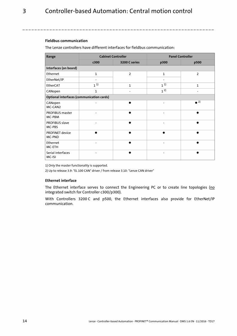
Fieldbus communication
The Lenze controllers have different interfaces for fieldbus communication:
1) Only the master functionality is supported.
2) Up to release 3.9: "EL 100 CAN" driver / from release 3.10: "Lenze CAN driver"
Ethernet interface
The Ethernet interface serves to connect the Engineering PC or to create line topologies (nointegrated switch for Controller c300/p300).
With Controllers 3200 C and p500, the Ethernet interfaces also provide for EtherNet/IPcommunication.
Range Cabinet Controller Panel Controller
c300 3200 C series p300 p500
Interfaces (on board)
Ethernet 1 2 1 2
EtherNet/IP - -
EtherCAT 1 1) 1 1 1) 1
CANopen 1 - 1 2) -
Optional interfaces (communication cards)
CANopenMC-CAN2
- - 2)
PROFIBUS masterMC-PBM
- -
PROFIBUS slaveMC-PBS
- -
PROFINET deviceMC-PND
EthernetMC-ETH
- -
Serial interfacesMC-ISI
- -
Lenze · Controller-based Automation · PROFINET® Communication Manual · DMS 1.6 EN · 11/2016 · TD17 15
4 The Lenze automation system with PROFINET
_ _ _ _ _ _ _ _ _ _ _ _ _ _ _ _ _ _ _ _ _ _ _ _ _ _ _ _ _ _ _ _ _ _ _ _ _ _ _ _ _ _ _ _ _ _ _ _ _ _ _ _ _ _ _ _ _ _ _ _ _ _ _ _
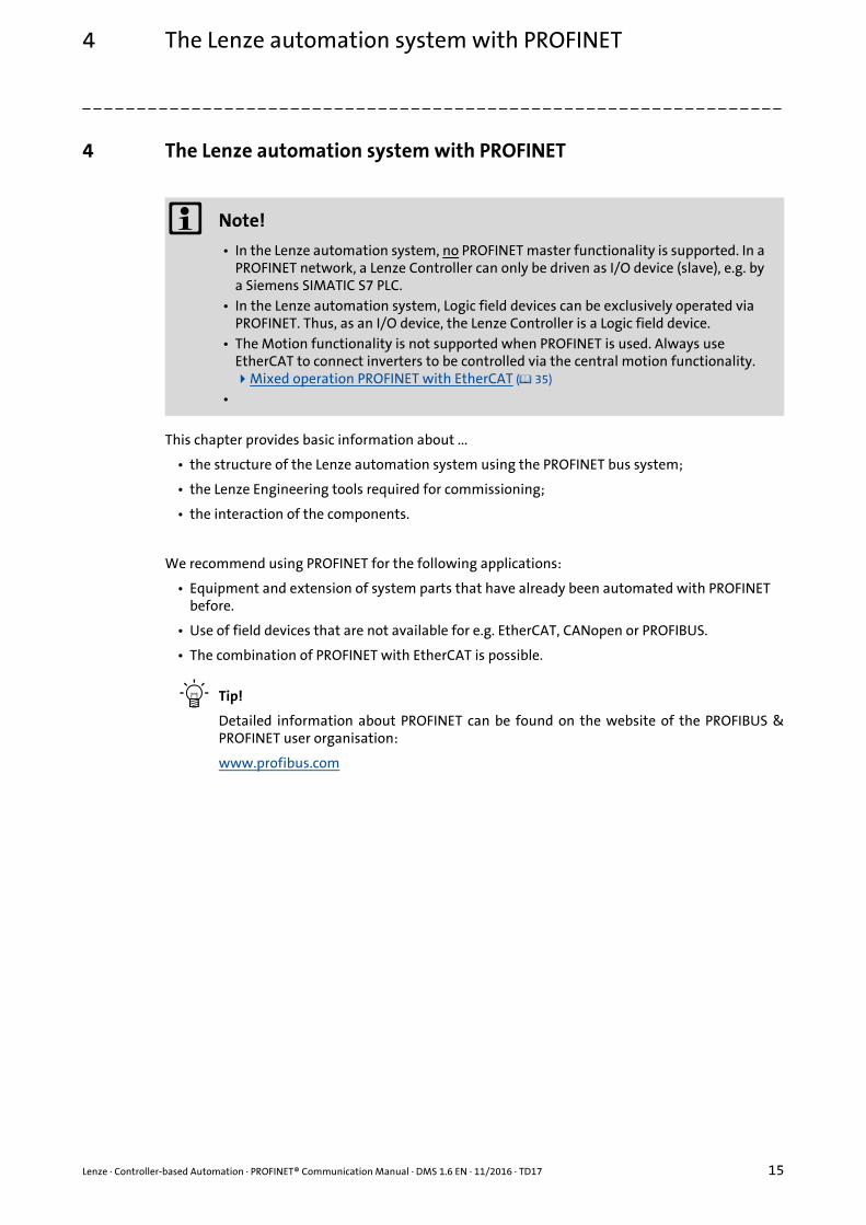
4 The Lenze automation system with PROFINET
This chapter provides basic information about ...
• the structure of the Lenze automation system using the PROFINET bus system;
• the Lenze Engineering tools required for commissioning;
• the interaction of the components.
We recommend using PROFINET for the following applications:
• Equipment and extension of system parts that have already been automated with PROFINET before.
• Use of field devices that are not available for e.g. EtherCAT, CANopen or PROFIBUS.
• The combination of PROFINET with EtherCAT is possible.
Tip!
Detailed information about PROFINET can be found on the website of the PROFIBUS &PROFINET user organisation:
www.profibus.com
Note!
• In the Lenze automation system, no PROFINET master functionality is supported. In a PROFINET network, a Lenze Controller can only be driven as I/O device (slave), e.g. by a Siemens SIMATIC S7 PLC.
• In the Lenze automation system, Logic field devices can be exclusively operated via PROFINET. Thus, as an I/O device, the Lenze Controller is a Logic field device.
• The Motion functionality is not supported when PROFINET is used. Always use EtherCAT to connect inverters to be controlled via the central motion functionality.Mixed operation PROFINET with EtherCAT ( 35)
•

4 The Lenze automation system with PROFINET4.1 Structure of the PROFINET system
16 Lenze · Controller-based Automation · PROFINET® Communication Manual · DMS 1.6 EN · 11/2016 · TD17
_ _ _ _ _ _ _ _ _ _ _ _ _ _ _ _ _ _ _ _ _ _ _ _ _ _ _ _ _ _ _ _ _ _ _ _ _ _ _ _ _ _ _ _ _ _ _ _ _ _ _ _ _ _ _ _ _ _ _ _ _ _ _ _
4.1 Structure of the PROFINET system
[4-1] Example: PROFINET configuration with a Siemens SIMATIC S7-PLC (Lenze Controller 3221 C with I/O system 1000 and Servo Drives 9400 as I/O devices)
Usually, field devices with PROFINET interface with an existing GSDML file can be used in aPROFINET network.
In the example (fig [4-1]), the Lenze Controller 3221 C together with the I/O system 1000 and twoServo Drives 9400 are driven as I/O devices by a Siemens SIMATIC S7 PLC.
The Lenze Controller is configured in the »PLC Designer« (see Commissioning of the PROFINET( 23)). When you log in with the »PLC Designer«, the configuration data is loaded into the LenzeController via Ethernet.
In order to integrate a Lenze Controller or other Lenze field devices into a »STEP7« project use theGSDML file of the device to be integrated.
Tip!
GSDML files of the Lenze Controllers and of other Lenze devices are provided in thedownload area at:
www.lenze.com

Lenze · Controller-based Automation · PROFINET® Communication Manual · DMS 1.6 EN · 11/2016 · TD17 17
4 The Lenze automation system with PROFINET4.2 Network topology
_ _ _ _ _ _ _ _ _ _ _ _ _ _ _ _ _ _ _ _ _ _ _ _ _ _ _ _ _ _ _ _ _ _ _ _ _ _ _ _ _ _ _ _ _ _ _ _ _ _ _ _ _ _ _ _ _ _ _ _ _ _ _ _
4.2 Network topology
It is typical of PROFINET to have a rather free topology, the limiting factor of which is large messagelatencies due to e.g. switches connected in series.
PROFINET supports the following topologies:
Line topology
[4-2] Line topology (M = I/O master, D = I/O device)
Star topology
[4-3] Star topology (M = I/O master, D = I/O device)
Tree topology
[4-4] Tree topology via switches (M = IO master, SW = switch, D = I/O device)
M
D D DD
M
D D D
sw
DD D
sw
DD D
sw
DD D
M

4 The Lenze automation system with PROFINET4.3 Field devices
18 Lenze · Controller-based Automation · PROFINET® Communication Manual · DMS 1.6 EN · 11/2016 · TD17
_ _ _ _ _ _ _ _ _ _ _ _ _ _ _ _ _ _ _ _ _ _ _ _ _ _ _ _ _ _ _ _ _ _ _ _ _ _ _ _ _ _ _ _ _ _ _ _ _ _ _ _ _ _ _ _ _ _ _ _ _ _ _ _
4.3 Field devices
The Lenze automation system supports the following PROFINET-capable Logic components:
1) With PROFINET communication module E94AYCER
2) With PROFINET communication module E84AYCER
Field devices of other manufacturers can be implemented if corresponding device descriptions areavailable.
Logic field devices
Controllers Cabinet Controller 32xx C
Panel Controller p500
Servo Drives 9400 1) HighLine
HighLine with CiA402
PLC
regenerative power supply module commissioning guidelines
Inverter Drives 8400 2) StateLine
HighLine
TopLine
I/O system 1000 EPM-Sxxx
Lenze · Controller-based Automation · PROFINET® Communication Manual · DMS 1.6 EN · 11/2016 · TD17 19
4 The Lenze automation system with PROFINET4.4 PROFINET hardware for Lenze Controllers
_ _ _ _ _ _ _ _ _ _ _ _ _ _ _ _ _ _ _ _ _ _ _ _ _ _ _ _ _ _ _ _ _ _ _ _ _ _ _ _ _ _ _ _ _ _ _ _ _ _ _ _ _ _ _ _ _ _ _ _ _ _ _ _
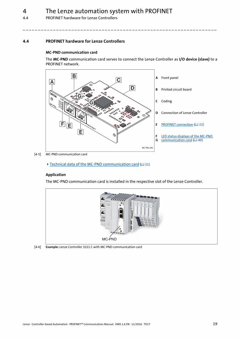
4.4 PROFINET hardware for Lenze Controllers
MC-PND communication card
The MC-PND communication card serves to connect the Lenze Controller as I/O device (slave) to aPROFINET network.
[4-5] MC-PND communication card
Technical data of the MC-PND communication card ( 21)
Application
The MC-PND communication card is installed in the respective slot of the Lenze Controller.
[4-6] Example: Lenze Controller 3221 C with MC-PND communication card
MC-PNx-001
A Front panel
B Printed circuit board
C Coding
D Connection of Lenze Controller
E PROFINET connection ( 22)
FG
LED status displays of the MC-PND communication card ( 40)
4 The Lenze automation system with PROFINET4.5 Lenze Engineering tools
20 Lenze · Controller-based Automation · PROFINET® Communication Manual · DMS 1.6 EN · 11/2016 · TD17
_ _ _ _ _ _ _ _ _ _ _ _ _ _ _ _ _ _ _ _ _ _ _ _ _ _ _ _ _ _ _ _ _ _ _ _ _ _ _ _ _ _ _ _ _ _ _ _ _ _ _ _ _ _ _ _ _ _ _ _ _ _ _ _
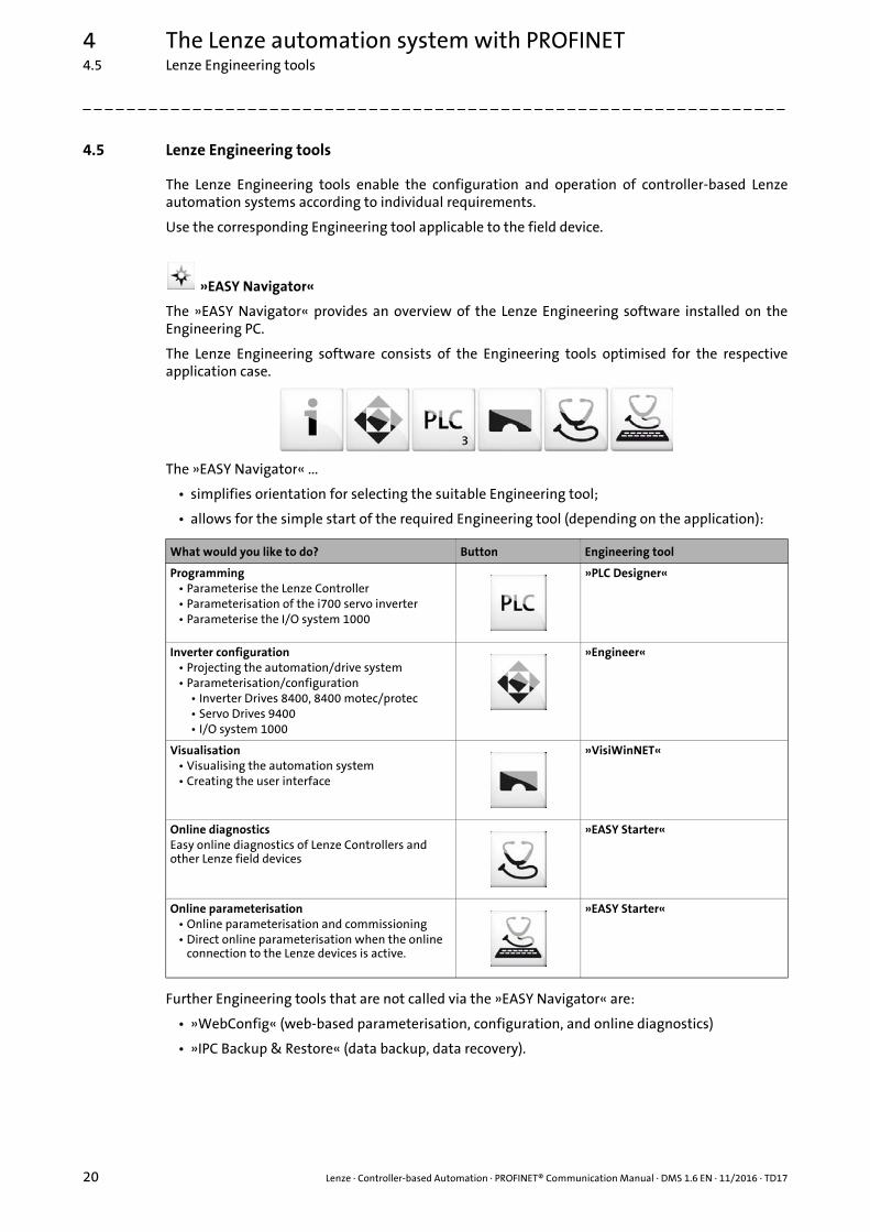
4.5 Lenze Engineering tools
The Lenze Engineering tools enable the configuration and operation of controller-based Lenzeautomation systems according to individual requirements.
Use the corresponding Engineering tool applicable to the field device.
»EASY Navigator«
The »EASY Navigator« provides an overview of the Lenze Engineering software installed on theEngineering PC.
The Lenze Engineering software consists of the Engineering tools optimised for the respectiveapplication case.
The »EASY Navigator« ...
• simplifies orientation for selecting the suitable Engineering tool;
• allows for the simple start of the required Engineering tool (depending on the application):
Further Engineering tools that are not called via the »EASY Navigator« are:
• »WebConfig« (web-based parameterisation, configuration, and online diagnostics)
• »IPC Backup & Restore« (data backup, data recovery).
What would you like to do? Button Engineering tool
Programming• Parameterise the Lenze Controller• Parameterisation of the i700 servo inverter• Parameterise the I/O system 1000
»PLC Designer«
Inverter configuration• Projecting the automation/drive system• Parameterisation/configuration
• Inverter Drives 8400, 8400 motec/protec• Servo Drives 9400• I/O system 1000
»Engineer«
Visualisation• Visualising the automation system• Creating the user interface
»VisiWinNET«
Online diagnosticsEasy online diagnostics of Lenze Controllers and other Lenze field devices
»EASY Starter«
Online parameterisation• Online parameterisation and commissioning• Direct online parameterisation when the online
connection to the Lenze devices is active.
»EASY Starter«

Lenze · Controller-based Automation · PROFINET® Communication Manual · DMS 1.6 EN · 11/2016 · TD17 21
5 Technical data5.1 Technical data of the MC-PND communication card
_ _ _ _ _ _ _ _ _ _ _ _ _ _ _ _ _ _ _ _ _ _ _ _ _ _ _ _ _ _ _ _ _ _ _ _ _ _ _ _ _ _ _ _ _ _ _ _ _ _ _ _ _ _ _ _ _ _ _ _ _ _ _ _
5 Technical data
5.1 Technical data of the MC-PND communication card
Range Values
Communication profile PROFINET
Communication medium / cable type
S/FTP (Screened Foiled Twisted Pair, ISO/IEC 11801 or EN 50173), CAT5eStandard Ethernet (in accordance with IEEE 802.3), 100Base-TX (Fast Ethernet)
Network topology Line, star and tree
Type within the network PROFINET I/O device (slave)
Max. cable length 100 m between two stations
I/O data (PDO data) • Max. 244 PDOs: Freely configurable, independent of its direction (In, Out, In/Out)
• Max. 1024 input bytes and max. 1024 output bytes• Scaling:
• Byte: 1, 2, 4, 8, 16, 32, 64, 128, 192, 256, 320, 384, 448, 512, 1024• Word: 1, 2, 4, 8, 16, 32, 64, 128, 192, 256, 320, 384, 448, 512
• The combination of I/O data in one slot is possible.
Communication type PROFINET I/O, cyclic
Functions • Transmission of cyclic process data• Context Management via CL-RPC (Connectionless Remote Procedure
Call)The Context Management Protocol is used for:• Connection establishment and termination• Request for resources• Exchange of configuration and diagnostic information• Upload/Download of data records
• Setpoint/actual value comparison of the PROFINET configuration
Special features in theLenze automation system
Configuration in the »PLC Designer«:• No submodules• Only one device instance is supported.
No support of ...• acyclic read and write requests• DCP (Discovery and basic Configuration Protocol)• RTP (Real-Time Transport Protocol) over UDP (User Datagram Protocol)• Multicast communication• Process-/diagnostics alarms• Generic diagnostics, channel diagnostics
Minimum cycle time 8 ms

5 Technical data5.2 PROFINET connection
22 Lenze · Controller-based Automation · PROFINET® Communication Manual · DMS 1.6 EN · 11/2016 · TD17
_ _ _ _ _ _ _ _ _ _ _ _ _ _ _ _ _ _ _ _ _ _ _ _ _ _ _ _ _ _ _ _ _ _ _ _ _ _ _ _ _ _ _ _ _ _ _ _ _ _ _ _ _ _ _ _ _ _ _ _ _ _ _ _
5.2 PROFINET connection
PROFINET is connected via the RJ45 sockets.
1) Bridged and terminate to PE via RC element.
2) Bridged and terminate to PE via RC element.
Tip!
The PROFINET interfaces feature an auto MDIX function. This function adjusts the polarityof the RJ45 interfaces so that a connection is established irrespective of the polarity of theopposite PROFINET interface, and irrespective of the cable type used (standard patch cableor crossover cable).
RJ45 socket Pin Assignment
MC-PNx-003
1 Tx +
2 Tx -
3 Rx +
4 Term1 1)
5 Term1 1)
6 Rx -
7 Term2 2)
8 Term2 2)
1 8

Lenze · Controller-based Automation · PROFINET® Communication Manual · DMS 1.6 EN · 11/2016 · TD17 23
6 Commissioning of the PROFINET6.1 Overview of the commissioning steps
_ _ _ _ _ _ _ _ _ _ _ _ _ _ _ _ _ _ _ _ _ _ _ _ _ _ _ _ _ _ _ _ _ _ _ _ _ _ _ _ _ _ _ _ _ _ _ _ _ _ _ _ _ _ _ _ _ _ _ _ _ _ _ _
6 Commissioning of the PROFINET
This chapter provides information on how to commission the Lenze automation system withPROFINET.
Depending on the field devices used, the following Lenze Engineering tools ( 20) are required:
• »EASY Starter«
• »Engineer«
• »PLC Designer«
6.1 Overview of the commissioning steps
The main commissioning steps are listed in the following table.
Note!
• In the Lenze automation system, no PROFINET master functionality is supported. In a PROFINET network, a Lenze Controller can only be driven as I/O device (slave), e.g. by a Siemens SIMATIC S7 PLC.
• In the Lenze automation system, Logic field devices can be exclusively operated via PROFINET. Thus, as an I/O device, the Lenze Controller is a Logic field device.
• The Motion functionality is not supported when PROFINET is used. Always use EtherCAT to connect inverters to be controlled via the central motion functionality.Mixed operation PROFINET with EtherCAT ( 35)
Step Activity Software to be used
1. Planning the bus topology ( 24)
2. Installing field devices ( 24)
3. Create a project folder ( 25)
4. Commission the field devices ( 25) »Engineer«/»EASY Starter«
If necessary, import the missing devices/device description files Importing missing devices / device description files ( 26)
»STEP7«
5th Creating a PLC program with a target system (Logic) ( 27) »PLC Designer«
6. Configuring the communication parameters ( 29)
6. Creating a control configuration (adding field devices) ( 31)
7. Configuring the I/O device ( 34)
8. Logging in on the controller with the »PLC Designer« ( 34) With the log-in, the I/O device configuration is loaded into the controller.

6 Commissioning of the PROFINET6.2 The commissioning steps in detail
24 Lenze · Controller-based Automation · PROFINET® Communication Manual · DMS 1.6 EN · 11/2016 · TD17
_ _ _ _ _ _ _ _ _ _ _ _ _ _ _ _ _ _ _ _ _ _ _ _ _ _ _ _ _ _ _ _ _ _ _ _ _ _ _ _ _ _ _ _ _ _ _ _ _ _ _ _ _ _ _ _ _ _ _ _ _ _ _ _
6.2 The commissioning steps in detail
In the following sections, the individual commissioning steps are described.
Follow the instructions of these sections step by step in order to commission your system.
6.2.1 Planning the bus topology
Before installing a PROFINET network, make a diagram of the network.
How to plan the bus topology for your configuration
1. Create an overview of the planned PROFINET network with all field devices to be integrated.
2. Start with the I/O master.
3. Add the other field devices (I/O devices) below.
6.2.2 Installing field devices
For the installation of a field device, follow the mounting instructions for the respective device.
More detailed information about how to work with the Lenze Engineering tools can be found in the corresponding manuals and online helps.
Mounting instructions of the field devices
Observe the safety instructions.
Lenze · Controller-based Automation · PROFINET® Communication Manual · DMS 1.6 EN · 11/2016 · TD17 25
6 Commissioning of the PROFINET6.2 The commissioning steps in detail
_ _ _ _ _ _ _ _ _ _ _ _ _ _ _ _ _ _ _ _ _ _ _ _ _ _ _ _ _ _ _ _ _ _ _ _ _ _ _ _ _ _ _ _ _ _ _ _ _ _ _ _ _ _ _ _ _ _ _ _ _ _ _ _
6.2.3 Create a project folder
Create a project folder on the Engineering PC.
Use this project folder to store the data generated in the following different project configurationsteps:
• Project data created in the »Engineer« or »EASY Starter«
• The project file created in the »PLC Designer«
Tip!
Create a separate project folder for every PROFINET configuration and store the projectfiles.
6.2.4 Commission the field devices
Parameterise the Lenze field devices connected to the PROFINET network by means of the»Engineer« or »EASY Starter«.
The PROFINET Lenze Controller is exclusively configured using the »PLC Designer«.
Other Lenze field devices receive their PROFINET configuration from the higher-level control (e.g. viathe »STEP7« project of a Siemens SIMATIC S7 PLC). PROFINET settings, which might be made by»Engineer«/»EASY Starter«, will be overwritten.
Tip!
We recommend to commission each field device individually and then integrate them intothe PLC program.
Documentation of the Lenze field devices
Here you are provided with some detailed information relating to the commissioning of the Lenze field devices.
6 Commissioning of the PROFINET6.2 The commissioning steps in detail
26 Lenze · Controller-based Automation · PROFINET® Communication Manual · DMS 1.6 EN · 11/2016 · TD17
_ _ _ _ _ _ _ _ _ _ _ _ _ _ _ _ _ _ _ _ _ _ _ _ _ _ _ _ _ _ _ _ _ _ _ _ _ _ _ _ _ _ _ _ _ _ _ _ _ _ _ _ _ _ _ _ _ _ _ _ _ _ _ _
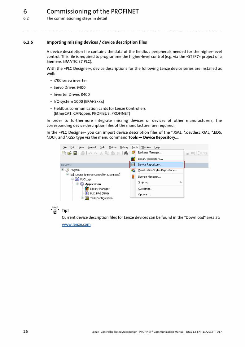
6.2.5 Importing missing devices / device description files
A device description file contains the data of the fieldbus peripherals needed for the higher-levelcontrol. This file is required to programme the higher-level control (e.g. via the »STEP7« project of aSiemens SIMATIC S7 PLC).
With the »PLC Designer«, device descriptions for the following Lenze device series are installed aswell:
• i700 servo inverter
• Servo Drives 9400
• Inverter Drives 8400
• I/O system 1000 (EPM-Sxxx)
• Fieldbus communication cards for Lenze Controllers(EtherCAT, CANopen, PROFIBUS, PROFINET)
In order to furthermore integrate missing devices or devices of other manufacturers, thecorresponding device description files of the manufacturer are required.
In the »PLC Designer« you can import device description files of the *.XML, *.devdesc.XML, *.EDS,*.DCF, and *.GSx type via the menu command Tools Device Repository....
Tip!
Current device description files for Lenze devices can be found in the "Download" area at:
www.lenze.com

Lenze · Controller-based Automation · PROFINET® Communication Manual · DMS 1.6 EN · 11/2016 · TD17 27
6 Commissioning of the PROFINET6.2 The commissioning steps in detail
_ _ _ _ _ _ _ _ _ _ _ _ _ _ _ _ _ _ _ _ _ _ _ _ _ _ _ _ _ _ _ _ _ _ _ _ _ _ _ _ _ _ _ _ _ _ _ _ _ _ _ _ _ _ _ _ _ _ _ _ _ _ _ _
6.2.6 Creating a PLC program with a target system (Logic)
By means of the »PLC Designer« you can map the network topology in the control configuration.
Tip!
In the »PLC Designer«, PROFINET stations and stations of other fieldbus systems can beconfigured.
Mixed operation PROFINET with EtherCAT ( 35)
How to create a PLC program in »PLC Designer«
1. Use the menu command File New project to create a new »PLC Designer« project.
2. Select "Standard project" in the New project dialog box.
A "Standard project" simplifies the structure of a project in the »PLC Designer«; for instance, a device tree structure with a target system, PLC logic, etc. is provided.
• Go to the Name input field and enter a name for your »PLC Designer« project.
• Select the previously created project folder as storage location in the Location selection field.Create a project folder ( 25)
3. Confirm the entries by clicking OK.
6 Commissioning of the PROFINET6.2 The commissioning steps in detail
28 Lenze · Controller-based Automation · PROFINET® Communication Manual · DMS 1.6 EN · 11/2016 · TD17
_ _ _ _ _ _ _ _ _ _ _ _ _ _ _ _ _ _ _ _ _ _ _ _ _ _ _ _ _ _ _ _ _ _ _ _ _ _ _ _ _ _ _ _ _ _ _ _ _ _ _ _ _ _ _ _ _ _ _ _ _ _ _ _
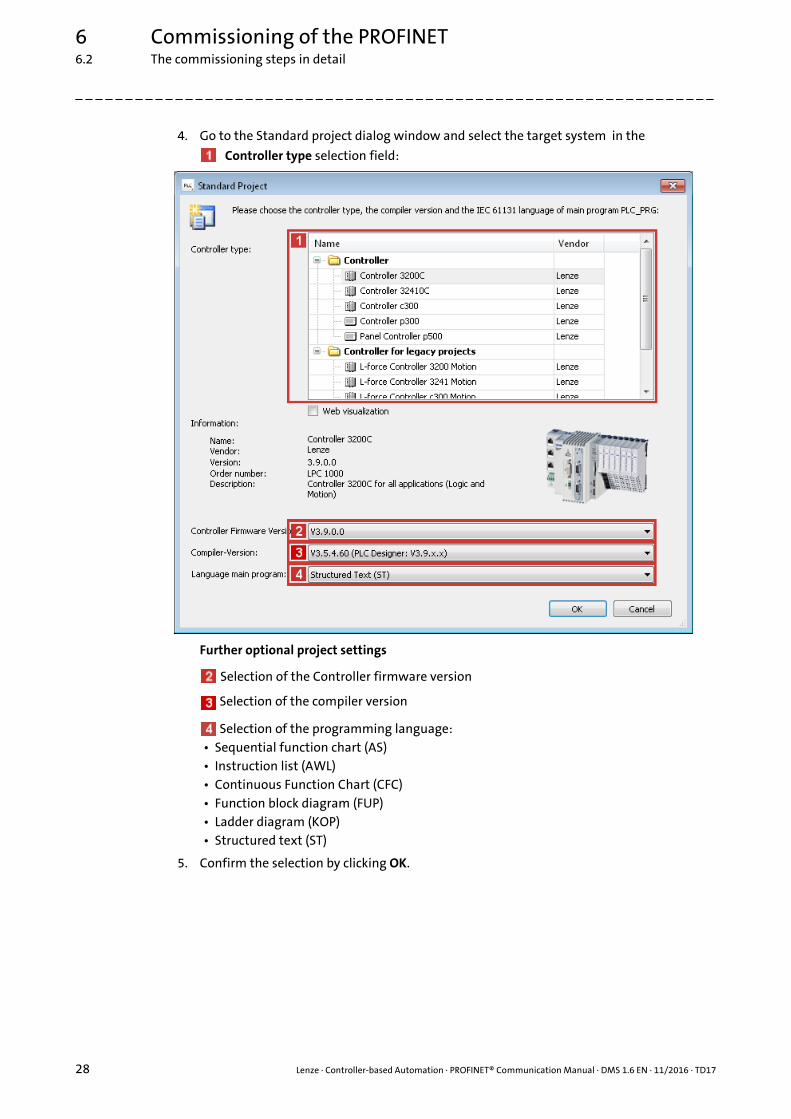
4. Go to the Standard project dialog window and select the target system in the
Controller type selection field:
Further optional project settings
Selection of the Controller firmware version
Selection of the compiler version
Selection of the programming language:• Sequential function chart (AS)• Instruction list (AWL)• Continuous Function Chart (CFC)• Function block diagram (FUP)• Ladder diagram (KOP)• Structured text (ST)
5. Confirm the selection by clicking OK.

Lenze · Controller-based Automation · PROFINET® Communication Manual · DMS 1.6 EN · 11/2016 · TD17 29
6 Commissioning of the PROFINET6.2 The commissioning steps in detail
_ _ _ _ _ _ _ _ _ _ _ _ _ _ _ _ _ _ _ _ _ _ _ _ _ _ _ _ _ _ _ _ _ _ _ _ _ _ _ _ _ _ _ _ _ _ _ _ _ _ _ _ _ _ _ _ _ _ _ _ _ _ _ _
6.2.7 Configuring the communication parameters
Set the communication parameters to establish an online connection to the Lenze Controller lateron.
How to configure the communication parameters:
1. Go to the Communication settings tab of the target system (device, Lenze Controller ...) and
click the Add gateway button.
Then go to the Gateway dialog box and enter the IP address of the controller. (By double-clicking the predefined value it can be overwritten.)
2. Confirm the entry by clicking OK.
6 Commissioning of the PROFINET6.2 The commissioning steps in detail
30 Lenze · Controller-based Automation · PROFINET® Communication Manual · DMS 1.6 EN · 11/2016 · TD17
_ _ _ _ _ _ _ _ _ _ _ _ _ _ _ _ _ _ _ _ _ _ _ _ _ _ _ _ _ _ _ _ _ _ _ _ _ _ _ _ _ _ _ _ _ _ _ _ _ _ _ _ _ _ _ _ _ _ _ _ _ _ _ _
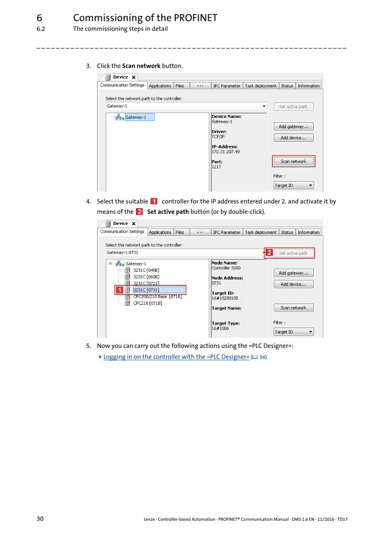
3. Click the Scan network button.
4. Select the suitable controller for the IP address entered under 2. and activate it by
means of the Set active path button (or by double-click).
5. Now you can carry out the following actions using the »PLC Designer«:
Logging in on the controller with the »PLC Designer« ( 34)

Lenze · Controller-based Automation · PROFINET® Communication Manual · DMS 1.6 EN · 11/2016 · TD17 31
6 Commissioning of the PROFINET6.2 The commissioning steps in detail
_ _ _ _ _ _ _ _ _ _ _ _ _ _ _ _ _ _ _ _ _ _ _ _ _ _ _ _ _ _ _ _ _ _ _ _ _ _ _ _ _ _ _ _ _ _ _ _ _ _ _ _ _ _ _ _ _ _ _ _ _ _ _ _
6.2.8 Creating a control configuration (adding field devices)
How to create the control configuration in the »PLC Designer«:
1. Go to the context menu of the target system (device, Lenze Controller ...) and use the
Add device command to extend the control configuration by the PROFINET I/O device.
Note!
The PROFINET Lenze Controller is exclusively configured using the »PLC Designer«.
Other Lenze field devices receive their PROFINET configuration from the higher-level control (e.g. via the »STEP7« project of a Siemens SIMATIC S7 PLC).
6 Commissioning of the PROFINET6.2 The commissioning steps in detail
32 Lenze · Controller-based Automation · PROFINET® Communication Manual · DMS 1.6 EN · 11/2016 · TD17
_ _ _ _ _ _ _ _ _ _ _ _ _ _ _ _ _ _ _ _ _ _ _ _ _ _ _ _ _ _ _ _ _ _ _ _ _ _ _ _ _ _ _ _ _ _ _ _ _ _ _ _ _ _ _ _ _ _ _ _ _ _ _ _
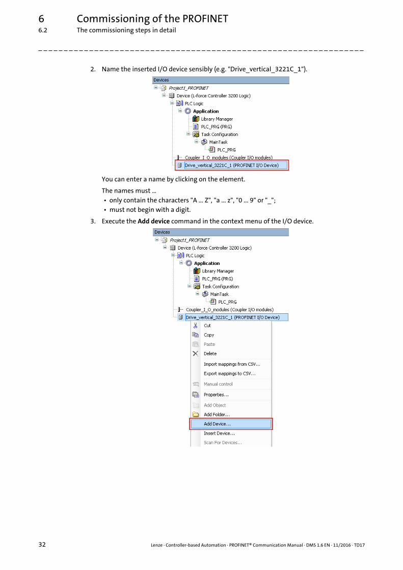
2. Name the inserted I/O device sensibly (e.g. "Drive_vertical_3221C_1").
You can enter a name by clicking on the element.
The names must …• only contain the characters "A ... Z", "a ... z", "0 ... 9" or "_";• must not begin with a digit.
3. Execute the Add device command in the context menu of the I/O device.

Lenze · Controller-based Automation · PROFINET® Communication Manual · DMS 1.6 EN · 11/2016 · TD17 33
6 Commissioning of the PROFINET6.2 The commissioning steps in detail
_ _ _ _ _ _ _ _ _ _ _ _ _ _ _ _ _ _ _ _ _ _ _ _ _ _ _ _ _ _ _ _ _ _ _ _ _ _ _ _ _ _ _ _ _ _ _ _ _ _ _ _ _ _ _ _ _ _ _ _ _ _ _ _
4. Select the I/O modules to be used for the I/O device in the "Add device" dialog window
and add it to the I/O device by using the Add device button.
5. Repeat the steps 1. ... 4. for further Lenze Controllers connected to the PROFINET.
Note!
The I/O modules defined by Lenze behave consistently.
If the value of a consistent module changes, the entire module is written on the bus in the same cycle.
In order to guarantee consistent data between master and slave, make sure that the master supports consistent modules as well.
6 Commissioning of the PROFINET6.2 The commissioning steps in detail
34 Lenze · Controller-based Automation · PROFINET® Communication Manual · DMS 1.6 EN · 11/2016 · TD17
_ _ _ _ _ _ _ _ _ _ _ _ _ _ _ _ _ _ _ _ _ _ _ _ _ _ _ _ _ _ _ _ _ _ _ _ _ _ _ _ _ _ _ _ _ _ _ _ _ _ _ _ _ _ _ _ _ _ _ _ _ _ _ _
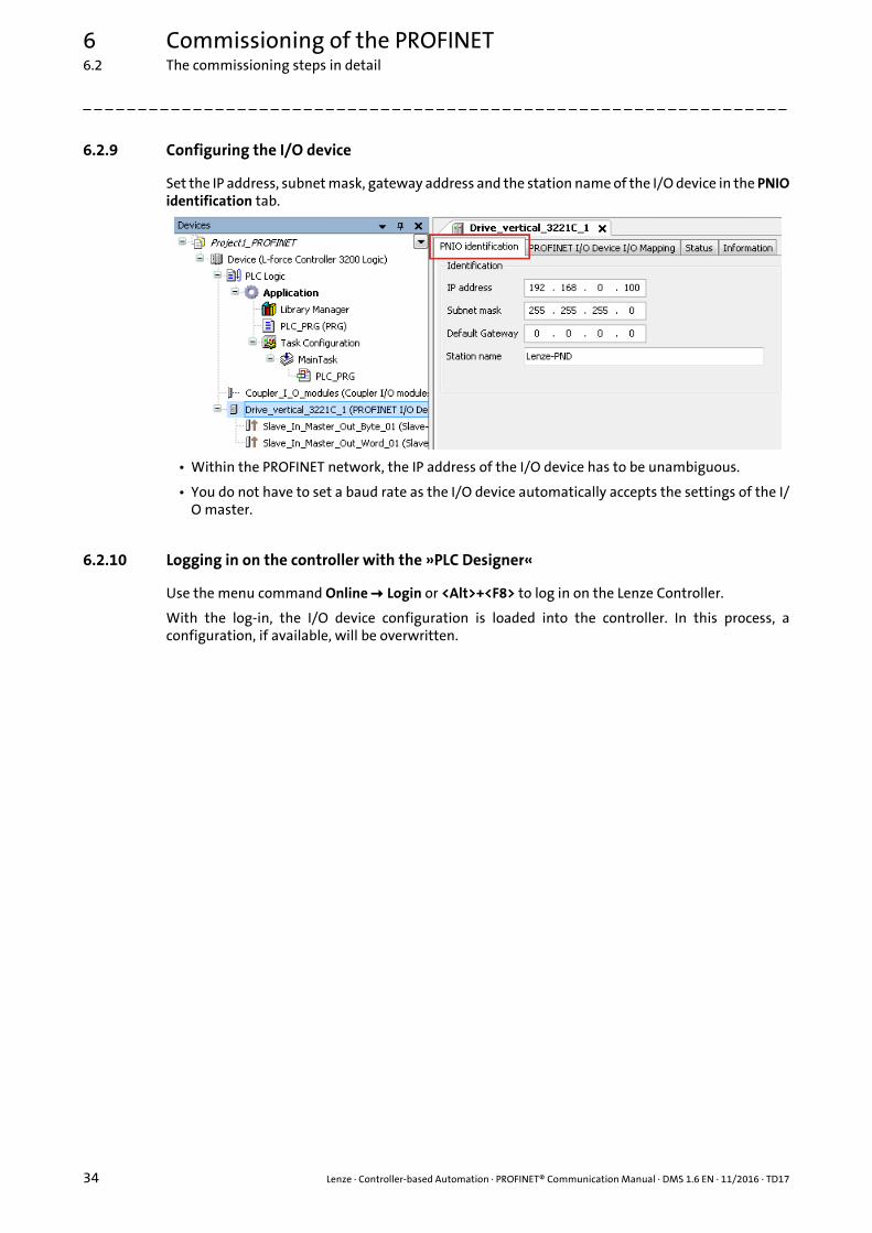
6.2.9 Configuring the I/O device
Set the IP address, subnet mask, gateway address and the station name of the I/O device in the PNIOidentification tab.
• Within the PROFINET network, the IP address of the I/O device has to be unambiguous.
• You do not have to set a baud rate as the I/O device automatically accepts the settings of the I/O master.
6.2.10 Logging in on the controller with the »PLC Designer«
Use the menu command Online Login or <Alt>+<F8> to log in on the Lenze Controller.
With the log-in, the I/O device configuration is loaded into the controller. In this process, aconfiguration, if available, will be overwritten.

Lenze · Controller-based Automation · PROFINET® Communication Manual · DMS 1.6 EN · 11/2016 · TD17 35
7 Mixed operation PROFINET with EtherCAT
_ _ _ _ _ _ _ _ _ _ _ _ _ _ _ _ _ _ _ _ _ _ _ _ _ _ _ _ _ _ _ _ _ _ _ _ _ _ _ _ _ _ _ _ _ _ _ _ _ _ _ _ _ _ _ _ _ _ _ _ _ _ _ _
7 Mixed operation PROFINET with EtherCAT
[7-1] Example: Mixed operation of PROFINET with EtherCAT on the Lenze Controller 3221 C
Within the Lenze Controller-based Automation, PROFINET can be used in parallel to the EtherCATbus system. This is useful if not all devices are available for the same bus system or if EtherCAT isrequired in parallel to PROFINET.
Controller-based Automation EtherCAT communication manual
Here you can find detailed information on how to commission EtherCAT components.
8 Defining the cycle time of the PLC project8.1 Determining the task utilisation of the application
36 Lenze · Controller-based Automation · PROFINET® Communication Manual · DMS 1.6 EN · 11/2016 · TD17
_ _ _ _ _ _ _ _ _ _ _ _ _ _ _ _ _ _ _ _ _ _ _ _ _ _ _ _ _ _ _ _ _ _ _ _ _ _ _ _ _ _ _ _ _ _ _ _ _ _ _ _ _ _ _ _ _ _ _ _ _ _ _ _
8 Defining the cycle time of the PLC project
In this chapter you'll learn how to ...
• Determining the task utilisation of the application ( 36);
• Optimising the system ( 38).
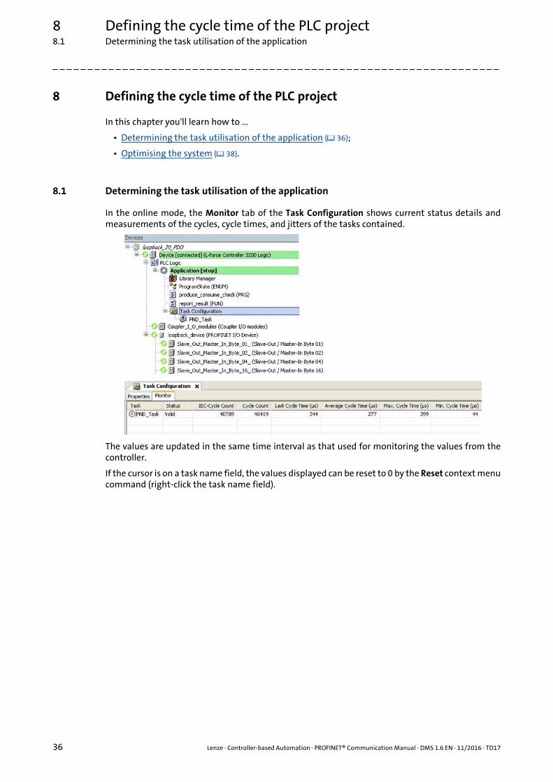
8.1 Determining the task utilisation of the application
In the online mode, the Monitor tab of the Task Configuration shows current status details andmeasurements of the cycles, cycle times, and jitters of the tasks contained.
The values are updated in the same time interval as that used for monitoring the values from thecontroller.
If the cursor is on a task name field, the values displayed can be reset to 0 by the Reset context menucommand (right-click the task name field).

Lenze · Controller-based Automation · PROFINET® Communication Manual · DMS 1.6 EN · 11/2016 · TD17 37
8 Defining the cycle time of the PLC project8.1 Determining the task utilisation of the application
_ _ _ _ _ _ _ _ _ _ _ _ _ _ _ _ _ _ _ _ _ _ _ _ _ _ _ _ _ _ _ _ _ _ _ _ _ _ _ _ _ _ _ _ _ _ _ _ _ _ _ _ _ _ _ _ _ _ _ _ _ _ _ _
How to determine the task utilisation:
Initial situation: A complete project, e.g. with a PROFINET task and 2 lower priority tasks has been created.
1. For a first measurement of the task utilisation, set the cycle times of all cyclic tasks available in the PLC system "high" (e.g. PROFINET task = 10 ms, all other cyclic tasks = 20 ms).
2. Use the menu command Online Login, or log in on the Lenze Controller with <Alt>+<F8>.
With the log-in, the I/O device configuration is loaded into the controller.
3. Reset the values displayed on the Monitor tab of the Task Configuration to 0 after the complete run-up of the system.
Execute the Reset command from the context menu of the task name field.
4. Read the displayed maximum computing time of the task with the highest priority.
In the illustration above, the max. cycle time of the PROFINET task is 399 μs.
The task cycle time does not have to be faster than the set PROFINET cycle time.
8 Defining the cycle time of the PLC project8.2 Optimising the system
38 Lenze · Controller-based Automation · PROFINET® Communication Manual · DMS 1.6 EN · 11/2016 · TD17
_ _ _ _ _ _ _ _ _ _ _ _ _ _ _ _ _ _ _ _ _ _ _ _ _ _ _ _ _ _ _ _ _ _ _ _ _ _ _ _ _ _ _ _ _ _ _ _ _ _ _ _ _ _ _ _ _ _ _ _ _ _ _ _
8.2 Optimising the system
How to optimise the system:
1. Use the menu command Online Login, or log in on the Lenze Controller with <Alt>+<F8>.
With the log-in, the I/O device configuration is loaded into the controller.
2. Check the task processing times.
3. Optimising the cycle times:• If technologically required, the cycle times of the remaining tasks with lower priorities
can be decreased.• Condition: No task with a low priority must assign more than 60 percent of the
corresponding cycle time in its task utilisation.
Lenze · Controller-based Automation · PROFINET® Communication Manual · DMS 1.6 EN · 11/2016 · TD17 39
9 Diagnostics
_ _ _ _ _ _ _ _ _ _ _ _ _ _ _ _ _ _ _ _ _ _ _ _ _ _ _ _ _ _ _ _ _ _ _ _ _ _ _ _ _ _ _ _ _ _ _ _ _ _ _ _ _ _ _ _ _ _ _ _ _ _ _ _
9 Diagnostics
The PROFINET field devices, communication modules and the MC-PND communication card areprovided with LED status displays for diagnostics.
Furthermore, the »PLC Designer« provides a function library for diagnosing PROFINET.
Note!
Siemens »STEP7«: "Node blinking test"
SIEMENS »STEP7« provides a "node blinking test" which permits an optical verification of the physical connection between the Siemens S7-PLC and a PROFINET node (I/O device).
Here, both LEDs are blinking at the RJ45 socket of the I/O device.
In »STEP7« version 5.5, this function is defective and does no create the wanted result.
Documentation of the field devices / PROFINET communication modules
Here you'll find some detailed information on the LED status displays of the field devices and communication modules.

9 Diagnostics9.1 LED status displays of the MC-PND communication card
40 Lenze · Controller-based Automation · PROFINET® Communication Manual · DMS 1.6 EN · 11/2016 · TD17
_ _ _ _ _ _ _ _ _ _ _ _ _ _ _ _ _ _ _ _ _ _ _ _ _ _ _ _ _ _ _ _ _ _ _ _ _ _ _ _ _ _ _ _ _ _ _ _ _ _ _ _ _ _ _ _ _ _ _ _ _ _ _ _
9.1 LED status displays of the MC-PND communication card
[9-1] LED status displays of the MC-PND communication card
MC-PNx-001_LED
ACTIVELINK
PROFINET
SYS
ST0
ST1
ST2
LED Colour Status Beschreibung
SYS Green On Operating system is running
Yellow Blinking once per second (1 Hz)
Error during boot process
On Boot loader waits for boot process
- Off No voltage supply or hardware is defective.
ST0 Red On System error: Watchdog timeoutChannel, generic or extended diagnostics is available.
Blinking once per second (1 Hz)
DCP signal is triggered via fieldbus.
Off No error
ST1 Red On No configuration or too slow physical connection or no physical connection
Blinking 2 times per second (2 Hz)
No data exchange
Off No error
ST2 - - No function
Link Green On Connection to Ethernet has been established.
Off No connection to Ethernet
Active Yellow Blinking Device transmits/receives Ethernet frames

Lenze · Controller-based Automation · PROFINET® Communication Manual · DMS 1.6 EN · 11/2016 · TD17 41
9 Diagnostics9.2 Diagnostics in the »PLC Designer«
_ _ _ _ _ _ _ _ _ _ _ _ _ _ _ _ _ _ _ _ _ _ _ _ _ _ _ _ _ _ _ _ _ _ _ _ _ _ _ _ _ _ _ _ _ _ _ _ _ _ _ _ _ _ _ _ _ _ _ _ _ _ _ _
9.2 Diagnostics in the »PLC Designer«
Only if an online connection to the Lenze Controller has been established, the Status tab displays
information on the PROFINET status and I/O device statuses:

10 Parameter reference
42 Lenze · Controller-based Automation · PROFINET® Communication Manual · DMS 1.6 EN · 11/2016 · TD17
_ _ _ _ _ _ _ _ _ _ _ _ _ _ _ _ _ _ _ _ _ _ _ _ _ _ _ _ _ _ _ _ _ _ _ _ _ _ _ _ _ _ _ _ _ _ _ _ _ _ _ _ _ _ _ _ _ _ _ _ _ _ _ _
10 Parameter reference
This chapter complements the parameter list in the online help of the Lenze Controller by theparameters of the MC-PND communication card.
These parameters ...
• are for instance shown in the Lenze »WebConfig« (Engineering tool for web-based parameterisation);
• are listed in numerically ascending order.
C1031
C1032
C1033
C1034
C1035
C1036
Parameter | Name:
C1031 | Device: type keyData type: VISIBLE_STRING
Index: 23544 = 0x5BF8
Identification of the card
Read access Write access CINH PLC-STOP No transfer
Parameter | Name:
C1032 | Device: type versionData type: VISIBLE_STRING
Index: 23543 = 0x5BF7
Version number of the card
Read access Write access CINH PLC-STOP No transfer
Parameter | Name:
C1033 | Device: nameData type: VISIBLE_STRING
Index: 23542 = 0x5BF6
Device name of the card
Read access Write access CINH PLC-STOP No transfer
Parameter | Name:
C1034 | Device: software revisionData type: VISIBLE_STRING
Index: 23541 = 0x5BF5
Software version of the card
Read access Write access CINH PLC-STOP No transfer
Parameter | Name:
C1035 | Device: hardware revisionData type: VISIBLE_STRING
Index: 23540 = 0x5BF4
Hardware version of the card
Read access Write access CINH PLC-STOP No transfer
Parameter | Name:
C1036 | Device: serial numberData type: VISIBLE_STRING
Index: 23539 = 0x5BF3
Serial number of the card
Read access Write access CINH PLC-STOP No transfer

Lenze · Controller-based Automation · PROFINET® Communication Manual · DMS 1.6 EN · 11/2016 · TD17 43
10 Parameter reference
_ _ _ _ _ _ _ _ _ _ _ _ _ _ _ _ _ _ _ _ _ _ _ _ _ _ _ _ _ _ _ _ _ _ _ _ _ _ _ _ _ _ _ _ _ _ _ _ _ _ _ _ _ _ _ _ _ _ _ _ _ _ _ _
C1037
C1038
Parameter | Name:
C1037 | Device: manufacturerData type: VISIBLE_STRING
Index: 23538 = 0x5BF2
Manufacturer of the card
Read access Write access CINH PLC-STOP No transfer
Parameter | Name:
C1038 | Device: manufacturing dateData type: VISIBLE_STRING
Index: 23537 = 0x5BF1
Manufacturing date of the card
Read access Write access CINH PLC-STOP No transfer

Index
44 Lenze · Controller-based Automation · PROFINET® Communication Manual · DMS 1.6 EN · 11/2016 · TD17
_ _ _ _ _ _ _ _ _ _ _ _ _ _ _ _ _ _ _ _ _ _ _ _ _ _ _ _ _ _ _ _ _ _ _ _ _ _ _ _ _ _ _ _ _ _ _ _ _ _ _ _ _ _ _ _ _ _ _ _ _ _ _ _
AAdding devices 31
Adding field devices 31
Application notes 9
Application software of the Lenze Controllers 13
CC1031 | Device: Identification 42
C1032 | Device: Version 42
C1033 | Device: Name 42
C1034 | Device: Software version 42
C1035 | Device: Hardware version 42
C1036 | Device: Serial number 42
C1037 | Device: Manufacturer 43
C1038 | Device: Manufacturing date 43
Cable length (max.) 21
Cable type 21
Codes 42
Commission the field devices 25
Commissioning of the PROFINET 23
Communication medium 21
Communication profile 21
Communication settings 29
Communication type 21
Configuring the communication parameters 29
Configuring the I/O device 34
Conventions used 6
Create a project folder 25
Creating a control configuration 31
Creating a PLC program with a target system (Logic) 27
Creating a target system (Logic) 27
Cycle time 21
DDefining the cycle time of the PLC project 36
Determining the task utilisation of the application 36
DeviceHardware version (C1035) 42Identification (C1031) 42Manufacturer (C1037) 43Manufacturing date (C1038) 43Name (C1033) 42Serial number (C1036) 42Software version (C1034) 42Version (C1032) 42
Diagnostics 39
Diagnostics with the »PLC Designer« 41
EEASY Navigator 20
E-mail to Lenze 46
Engineering software 20
Engineering tools 20
FFeedback to Lenze 46
Field devices 18
Fieldbus communication (interfaces) 14
Functions of the MC-PND communication card 21
GGSDML file for configuration 16
II/O data 21
Importing device description files 26
Importing missing devices 26
Installing field devices 24
Interfaces for fieldbus communication 14
LLayout of the safety instructions 9
LED status displays of the MC-PND communication card 40
Lenze Engineering tools 20
Logging in on the controller 34
Logging in on the controller with the »PLC Designer« 34
MMC-PND communication card 19
MC-PND communication card, LED status displays 40
MC-PND communication card, technical data 21
Mixed operation PROFINET with EtherCAT 35
NNetwork topology 17, 21
OOptimising the system 38
PParameter reference 42
PDO data 21
PNIO identification 34
PROFINET 15
PROFINET connection 22
PROFINET hardware for Lenze Controllers 19
PROFINET system (structure) 16
PROFINET with EtherCAT (mixed operation) 35
Index

Lenze · Controller-based Automation · PROFINET® Communication Manual · DMS 1.6 EN · 11/2016 · TD17 45
Index
_ _ _ _ _ _ _ _ _ _ _ _ _ _ _ _ _ _ _ _ _ _ _ _ _ _ _ _ _ _ _ _ _ _ _ _ _ _ _ _ _ _ _ _ _ _ _ _ _ _ _ _ _ _ _ _ _ _ _ _ _ _ _ _
SSafety instructions 9, 10
Screenshots 4
Software 20
Special features of the MC-PND communication card 21
Status 41
Status displays of the MC-PND communication card 40
Structure of the PROFINET system 16
System structure of Controller-based Automation 12
TTarget group 4
Task configuration 36
Technical data 21
Technical data of the MC-PND communication card 21
Terms 7
Type within the network 21

46
Your opinion is important to usThese instructions were created to the best of our knowledge andbelief to give you the best possible support for handling our product.
Perhaps we have not succeeded in achieving this objective in everyrespect. If you have suggestions for improvement, please e-mail usto:
Thank you very much for your support.
Your Lenze documentation team
L
Controller-based Automation · PROFINET® Communication Manual · KHBPNETPCBAUTO · 13523809 · DMS 1.6 EN · 11/2016 · TD17
Lenze Automation GmbHPostfach 10 13 52, 31763 HamelnHans-Lenze-Straße 1, 31855 AerzenGERMANYHR Hannover B 205381
+49 5154 82-0 +49 5154 82-2800 [email protected] www.lenze.com
ServiceLenze Service GmbHBreslauer Straße 3, 32699 ExtertalGERMANY
008000 24 46877 (24 h helpline) +49 5154 82-1112 [email protected]