Embed Size (px)
Citation preview
INSTRUCTION MANUAL
iR2500COMMUNICATION RECEIVER
This device complies with Part 15 of the FCC rules. Operation is sub-ject to the following two conditions: (1) This device may not causeharmful interference, and (2) this device must accept any interferencereceived, including interference that may cause undesired operation.
i
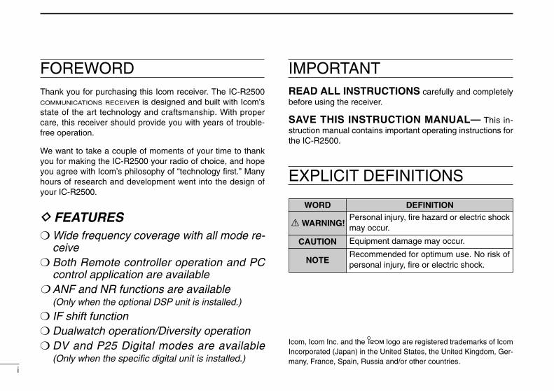
FOREWORDThank you for purchasing this Icom receiver. The IC-R2500COMMUNICATIONS RECEIVER is designed and built with Icom’sstate of the art technology and craftsmanship. With propercare, this receiver should provide you with years of trouble-free operation.
We want to take a couple of moments of your time to thankyou for making the IC-R2500 your radio of choice, and hopeyou agree with Icom’s philosophy of “technology first.” Manyhours of research and development went into the design ofyour IC-R2500.
D FEATURES❍ Wide frequency coverage with all mode re-
ceive❍ Both Remote controller operation and PC
control application are available❍ ANF and NR functions are available
(Only when the optional DSP unit is installed.)
❍ IF shift function❍ Dualwatch operation/Diversity operation❍ DV and P25 Digital modes are available
(Only when the specific digital unit is installed.)
IMPORTANTREAD ALL INSTRUCTIONS carefully and completelybefore using the receiver.
SAVE THIS INSTRUCTION MANUAL— This in-struction manual contains important operating instructions forthe IC-R2500.
EXPLICIT DEFINITIONS
WORD DEFINITION
R WARNING!
CAUTION
NOTE
Personal injury, fire hazard or electric shockmay occur.
Equipment damage may occur.
Recommended for optimum use. No risk ofpersonal injury, fire or electric shock.
Icom, Icom Inc. and the logo are registered trademarks of IcomIncorporated (Japan) in the United States, the United Kingdom, Ger-many, France, Spain, Russia and/or other countries.
ii
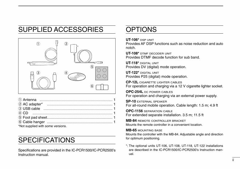
SUPPLIED ACCESSORIES
q Antenna …………………………………………………… 1w AC adapter* ……………………………………………… 1e USB cable ………………………………………………… 1r CD ………………………………………………………… 1t Foot pad sheet……………………………………………… 1y Cable hanger ……………………………………………… 1*Not supplied with some versions.
y
t
re
q w
OPTIONSUT-106* DSP UNIT
Provides AF DSP functions such as noise reduction and autonotch.
UT-108* DTMF DECODER UNIT
Provides DTMF decode function for sub band.
UT-118* DIGITAL UNIT
Provides DV (digital) mode operation.
UT-122* DIGITAL UNIT
Provides P25 (digital) mode operation.
CP-12L CIGARETTE LIGHTER CABLES
For operation and charging via a 12 V cigarette lighter socket.
OPC-254L DC POWER CABLES
For operation and charging via an external power supply.
SP-10 EXTERNAL SPEAKER
For all-round mobile operation. Cable length: 1.5 m; 4.9 ft
OPC-1156 SEPARATION CABLE
For extended separate installation. 3.5 m; 11.5 ft
MB-84 REMOTE CONTROLLER BRACKET
Mounts the remote controller in a convenient location.
MB-65 MOUNTING BASE
Mounts the controller with the MB-84. Adjustable angle and directionfor optimum positioning.
*: The optional units UT-106, UT-108, UT-118, UT-122 installationsare described in the IC-PCR1500/IC-PCR2500’s Instruction man-ual.
SPECIFICATIONSSpecifications are provided in the IC-PCR1500/IC-PCR2500’sInstruction manual.
iii
RWARNING! NEVER connect the receiver via theOPC-254L to an AC outlet. This may pose a fire hazard or re-sult in an electric shock.
RWARNING! NEVER operate the receiver while dri-ving a vehicle. Safe driving requires your full attention— any-thing less may result in an accident.
NEVER connect the receiver to a power source of morethan 14 V DC. This will damage the receiver.
NEVER connect the receiver to a power source using re-verse polarity. This will damage the receiver.
NEVER cut the DC power cable between the DC plug andfuse holder. If an incorrect connection is made after cutting,the receiver may be damaged.
DO NOT leave the main unit powered ON and connectedto a vehicle’s electrical system. The main unit draws approx.550 mA. This will eventually drain the vehicle’s battery.
NEVER expose the receiver to rain, snow or any liquids.The receiver may be damaged.
NEVER operate or touch the receiver with wet hands. Thismay result in an electric shock or damage the receiver.
NEVER place the receiver where normal operation of thevehicle may be hindered or where it could cause bodily injury.
NEVER let objects impede the operation of the cooling fanon the rear panel.
AVOID using or placing the receiver in direct sunlight or inareas with temperatures below –10°C (+14°F) or above+60°C (+140°F).
BE CAREFUL! The receiver will become hot when op-erating it continuously for long periods.
AVOID setting the receiver in a place without adequateventilation. Heat dissipation may be affected, and the receivermay be damaged.
AVOID the use of chemical agents such as benzine or al-cohol when cleaning, as they can damage the receiver’s sur-faces.
For U.S.A. onlyCAUTION: Changes or modifications to this device, not ex-pressly approved by Icom Inc., could void your authority tooperate this device under FCC regulations.
PRECAUTIONS
iv
ABOUT APCO PROJECT 25This device made under license under one or more of the fol-lowing US patents: #4,590,473, #4,636,791, #5,148,482,#5,185,796, #5,271,017, #5,377,229.
The IMBE™ voice coding technology embodied in this productis protected by intellectual property rights including patentrights, copyrights and trade secrets of Digital Voice Systems,Inc. This voice coding Technology is licensed solely for usewithin this communications equipment. The user of this tech-nology is explicitly prohibited from attempting to decompile, re-verse engineer, or disassemble the object code, or in anyother way convert the object code into a human-readableform. U.S. Pat. nos. #5,870,405, #5,826,222, #5,754,974,#5,701,390, #5,715,365, #5,649,050, #5,630,011, #5,581,656,#5,517,511, #5,491,772, #5,247,579, #5,226,084, #5,195,166.
P25 digital mode is available when the optional UT-122 DIG-ITAL UNIT is installed.
v
TABLE OF CONTENTSFOREWORD .............................................................. iIMPORTANT ............................................................... iEXPLICIT DEFINITIONS ............................................ iSUPPLIED ACCESSORIES ...................................... iiSPECIFICATIONS ..................................................... iiOPTIONS ................................................................... iiPRECAUTIONS ........................................................ iiiABOUT APCO PROJECT 25 .................................... ivTABLE OF CONTENTS ............................................. v
1 CONNECTION ................................................. 1–2■ Rear panel connection....................................... 1■ Antenna installation .......................................... 2
2 PANEL DESCRIPTION .................................. 3–10■ Front panel—controller ..................................... 3■ Function display ................................................ 7■ Rear panel—main unit ...................................... 9
3 SETTING A FREQUENCY ........................... 11–13■ Preparation ..................................................... 11■ Tuning step selection ...................................... 12■ Using the tuning dial ....................................... 13■ Receive mode selection ................................. 13
4 BASIC OPERATION .................................... 14–22■ Receiving ........................................................ 14■ Monitor function .............................................. 14■ Lock function .................................................. 15
■ Attenuator function .......................................... 15■ NB function ..................................................... 16■ AGC function .................................................. 16■ AFC function ................................................... 17■ VSC function ................................................... 17■ IF filter selection ............................................. 18■ IF shift function ............................................... 18■ Duplex operation ............................................ 19■ Weather channel operation
(USA versions only) ............................................ 20■ Single band operation ..................................... 22
5 MEMORY OPERATION ............................... 23–32■ General description ........................................ 23■ Memory channel selection .............................. 23■ Programming a memory channel ................... 24■ Programming channel names ........................ 25■ Copying memory contents .............................. 27■ Memory clearing ............................................. 29■ Memory bank setting ...................................... 30■ Memory bank selection ................................... 31■ Transferring bank contents ............................. 31
6 SCAN OPERATION ..................................... 33–37■ Scan types ...................................................... 33■ Scan start/stop ................................................ 34■ Scan edges programming .............................. 35■ Skip scan ........................................................ 36■ Scan resume condition ................................... 37
vi
1234567891011121314
7 PRIORITY WATCH ............................................ 38■ Priority watch types ........................................ 38■ Priority watch operation .................................. 38
8 POCKET BEEP AND TONE SQUELCH ..... 39–42■ Pocket beep operation .................................... 39■ Tone/DTCS squelch operation ........................ 41■ Tone scan ....................................................... 42
9 DIGITAL MODE OPERATION ..................... 43–48■ Digital mode operation .................................... 43■ Pocket beep operation .................................... 43■ Digital squelch operation ................................ 45■ Call sign programming (for DV mode) ............... 47■ ID code programming (for P25 mode) ............... 48
10 SET MODE ................................................... 49–64■ General ........................................................... 49■ Set mode items ............................................... 49
11 OTHER FUNCTIONS ................................... 65–68■ DSP operation (Optional UT-106 is required)....... 65■ DATA cloning
(IC-PCR2500 control software must be installed) ... 66■ Partial reset ..................................................... 67■ All reset............................................................ 67■ Internal audio switch........................................ 68
12 TROUBLESHOOTING ....................................... 6913 DOC ................................................................... 70
1
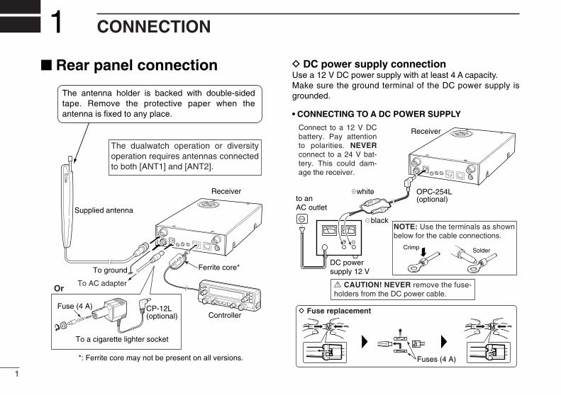
CONNECTION1■ Rear panel connection D DC power supply connection
Use a 12 V DC power supply with at least 4 A capacity. Make sure the ground terminal of the DC power supply isgrounded.
• CONNECTING TO A DC POWER SUPPLY
OPC-254L(optional)
black
white
R CAUTION! NEVER remove the fuse-holders from the DC power cable.
Connect to a 12 V DC battery. Pay attention to polarities. NEVERconnect to a 24 V bat-tery. This could dam-age the receiver.
SolderCrimp
NOTE: Use the terminals as shown below for the cable connections.
D Fuse replacement
Receiver
Fuses (4 A)
DC powersupply 12 V
to an AC outlet
−⊕
Ferrite core*
*: Ferrite core may not be present on all versions.
ControllerCP-12L(optional)
To a cigarette lighter socket
Fuse (4 A)
Or
Receiver
To ground
Supplied antenna
The antenna holder is backed with double-sided tape. Remove the protective paper when the antenna is fixed to any place.
To AC adapter
The dualwatch operation or diversity operation requires antennas connected to both [ANT1] and [ANT2].
2
1CONNECTION
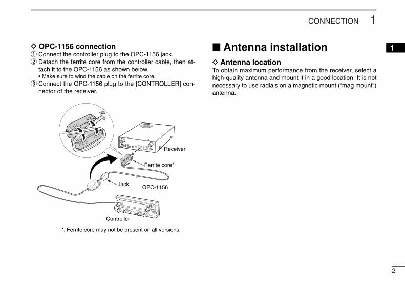
1D OPC-1156 connectionq Connect the controller plug to the OPC-1156 jack.w Detach the ferrite core from the controller cable, then at-
tach it to the OPC-1156 as shown below.• Make sure to wind the cable on the ferrite core.
e Connect the OPC-1156 plug to the [CONTROLLER] con-nector of the receiver.
■ Antenna installationD Antenna locationTo obtain maximum performance from the receiver, select ahigh-quality antenna and mount it in a good location. It is notnecessary to use radials on a magnetic mount (“mag mount”)antenna.
Receiver
OPC-1156
Controller
Jack
Ferrite core*
*: Ferrite core may not be present on all versions.

3
PANEL DESCRIPTION2
MAINAGC
S.MW
TS
VFO/MR
MHz
MAINNB
S.MWVFO/MR
TSMHz
VOLVOL
DIALDIALSQLSQL
MONIT/T-SCAN
MODESCAN
ATTPRIO
COMMUNICATIONS RECEIVER iR2500
PWR SETSKIP
Function display (pgs. 7, 8)q w
ert
The keys w to t are for the main band only.
■ Front panel—controller
4
2PANEL DESCRIPTION
12345678910111213141516
qPOWER KEY [PWR• ]➥ Push and hold for 1 sec. to turn the controller power ON
and OFF. (p. 11)➥ Continue to hold this key down for 2 sec. after power
ON to turn the lock function ON and OFF. (p. 15)
wSET•SKIP KEY [SET•SKIP]➥ Push to enter set mode. (p. 49)➥ Push and hold for 1 sec. to turn the channel skip setting
ON and OFF for memory/VFO skip scan operation. (p. 36)
e ATTENUATOR/PRIORITY KEY [ATT•PRIO]➥ Push to turn the ATT (Attenuator) function ON and OFF.
(p. 15)➥ Push and hold for 1 sec. to start priority watch. (p. 38)
r MODE•SCAN KEY [MODE•SCAN]➥ Push and hold for 1 sec. to enter receive mode select
mode. (p. 13)• Rotate main band’s [DIAL] to select the desired receive
mode.➥ Push and hold for 1 sec. to start a scan. (p. 34)
• Cancels a scan when pushed during scan.
t MONITOR•TONE•TONE SCAN KEY[MONI•T/T-SCAN]➥ Push to turn the monitor function ON and OFF. (p. 14)➥ Push and hold for 1 sec. to enter the tone function se-
lection mode. (pgs. 34, 41, 44, 46)• Pocket beep (CTCSS), tone squelch, pocket beep (DTCS),
DTCS squelch or tone function OFF can be selected in FMmode.
• Pocket beep (DSQL), digital call sign squelch, pocket beep(CSQL), digital code squelch or digital squelch function OFFcan be selected in DV*1 mode.
• Pocket beep (NAC), digital NAC squelch, pocket beep (Se-lective), digital selective squelch or digital squelch functionOFF can be selected in P25*2 mode.
*1: The optional UT-118 is required.*2: The optional UT-122 is required.
Some versions already come with the UT-122 installed.➥ Push and hold for 1 sec. during tone function selection
mode to start the tone scan. (p. 42)
5
2 PANEL DESCRIPTION
MAINAGC
S.MW
TS
VFO/MR
MHz
MAINNB
S.MWVFO/MR
TSMHz
VOLVOL
DIALDIALSQLSQL
MONIT/T-SCAN
MODESCAN
ATTPRIO
COMMUNICATIONS RECEIVER iR2500
PWR SETSKIP
Left band Right band
o o
yb
u
i
!0
ya
u
i
!0
!1!1
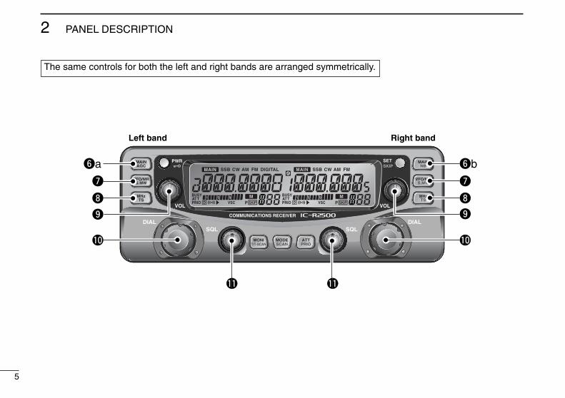
The same controls for both the left and right bands are arranged symmetrically.
6
2PANEL DESCRIPTION
12345678910111213141516
ya MAIN•AGC KEY [MAIN•AGC]➥ Push to select the left band as main band. (p. 11)➥ Push and hold for 1 sec. to turn the AGC (Automatic
Gain Control) function ON and OFF. (p. 16)
yb MAIN•NB KEY [MAIN•NB]➥ Push to select the right band as main band. (p. 11)➥ Push and hold for 1 sec. to turn the NB (Noise Blanker)
function ON and OFF. (p. 16)
uVFO/MEMORY•MEMORY WRITE KEY [VFO/MR•S.MW]➥ Push to select from VFO, memory and weather chan-
nel* modes. (pgs. 11, 20, 23)*Weather channels available for USA versions only.
➥ Push and hold for 1 sec. to enter select memory writemode for memory channel programming. (pgs. 24, 25,35)
iMHz TUNING•TUNING STEP [MHz•TS]➥ Push to select from band selection, 1 MHz or 10 MHz
tuning. (p. 13)➥ Push and hold for 1 sec. to enter tuning step select
mode. (p. 12)• Rotate [DIAL] to select the desired tuning step.
oVOLUME CONTROL [VOL] (p. 14)Adjusts the audio level for left and right band.
!0TUNING DIAL [DIAL]Selects the operating frequency (p. 13), memory channel(p. 23), the setting of the set mode item and the scanningdirection (p. 34) for left and right band.
!1SQUELCH CONTROL [SQL]Varies the squelch level for left and right band. (p. 14)
7
2 PANEL DESCRIPTION
■ Function display
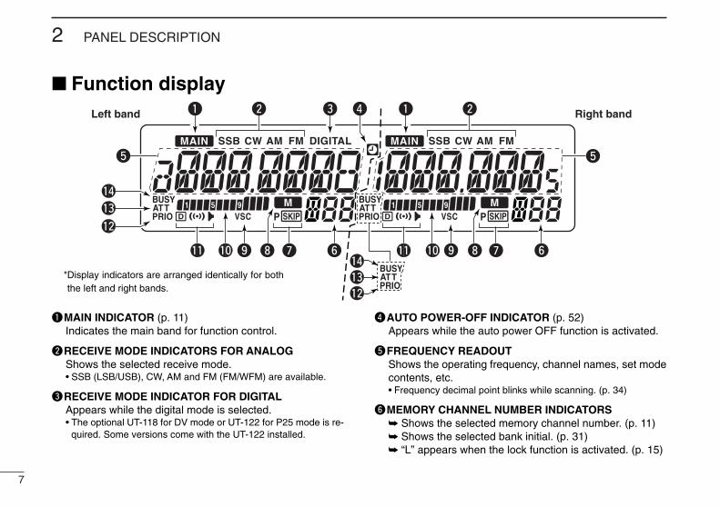
qMAIN INDICATOR (p. 11)Indicates the main band for function control.
wRECEIVE MODE INDICATORS FOR ANALOGShows the selected receive mode.• SSB (LSB/USB), CW, AM and FM (FM/WFM) are available.
eRECEIVE MODE INDICATOR FOR DIGITALAppears while the digital mode is selected.• The optional UT-118 for DV mode or UT-122 for P25 mode is re-
quired. Some versions come with the UT-122 installed.
rAUTO POWER-OFF INDICATOR (p. 52)Appears while the auto power OFF function is activated.
tFREQUENCY READOUTShows the operating frequency, channel names, set modecontents, etc.• Frequency decimal point blinks while scanning. (p. 34)
yMEMORY CHANNEL NUMBER INDICATORS ➥ Shows the selected memory channel number. (p. 11)➥ Shows the selected bank initial. (p. 31)➥ “L” appears when the lock function is activated. (p. 15)
Left band Right band
tt
!3
q ew q wr
yy uu oo !0!0
!2
!1!1 ii
!4
!3!4
!2
*Display indicators are arranged identically for boththe left and right bands.
8
2PANEL DESCRIPTION
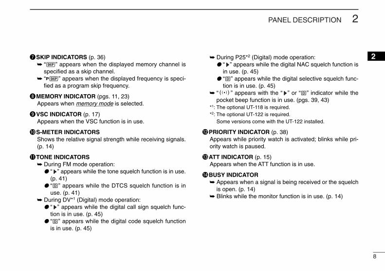
2uSKIP INDICATORS (p. 36)➥ “~” appears when the displayed memory channel is
specified as a skip channel.➥ “P~” appears when the displayed frequency is speci-
fied as a program skip frequency.
iMEMORY INDICATOR (pgs. 11, 23)Appears when memory mode is selected.
oVSC INDICATOR (p. 17)Appears when the VSC function is in use.
!0S-METER INDICATORSShows the relative signal strength while receiving signals.(p. 14)
!1TONE INDICATORS➥ During FM mode operation:
●● “ ” appears while the tone squelch function is in use.(p. 41)
●● “ ” appears while the DTCS squelch function is inuse. (p. 41)
➥ During DV*1 (Digital) mode operation:●● “ ” appears while the digital call sign squelch func-
tion is in use. (p. 45)●● “ ” appears while the digital code squelch function
is in use. (p. 45)
➥ During P25*2 (Digital) mode operation:●● “ ” appears while the digital NAC squelch function is
in use. (p. 45)●● “ ” appears while the digital selective squelch func-
tion is in use. (p. 45)➥ “S” appears with the “ ” or “ ” indicator while the
pocket beep function is in use. (pgs. 39, 43)*1: The optional UT-118 is required.*2: The optional UT-122 is required.
Some versions come with the UT-122 installed.
!2PRIORITY INDICATOR (p. 38)Appears while priority watch is activated; blinks while pri-ority watch is paused.
!3ATT INDICATOR (p. 15)Appears when the ATT function is in use.
!4BUSY INDICATOR ➥ Appears when a signal is being received or the squelch
is open. (p. 14)➥ Blinks while the monitor function is in use. (p. 14)
9
2 PANEL DESCRIPTION
■ Rear panel—main unit
Front
Top
RearPower switch
Speaker
DATA
PACKET 1USB EXT SPANT 1 ANT 2
DC IN
GND
PACKET 2
q w e r q
ti
u y
2-conductor 3.5 (d) mm (1⁄8˝)/100 k
PACKET jack connection
2-conductor 3.5 (d) mm (1⁄8˝)/8
EXT SP jack connectionAUDIO
GND
AUDIO
GND
Left band Right band
10
2PANEL DESCRIPTION
2
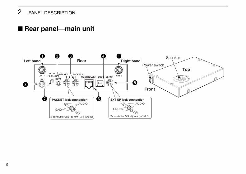
qANTENNA CONNECTORS [ANT]Connect a 50 antenna with a BNC connector and a50 coaxial cable. [ANT1] for left band, [ANT2] for right band.
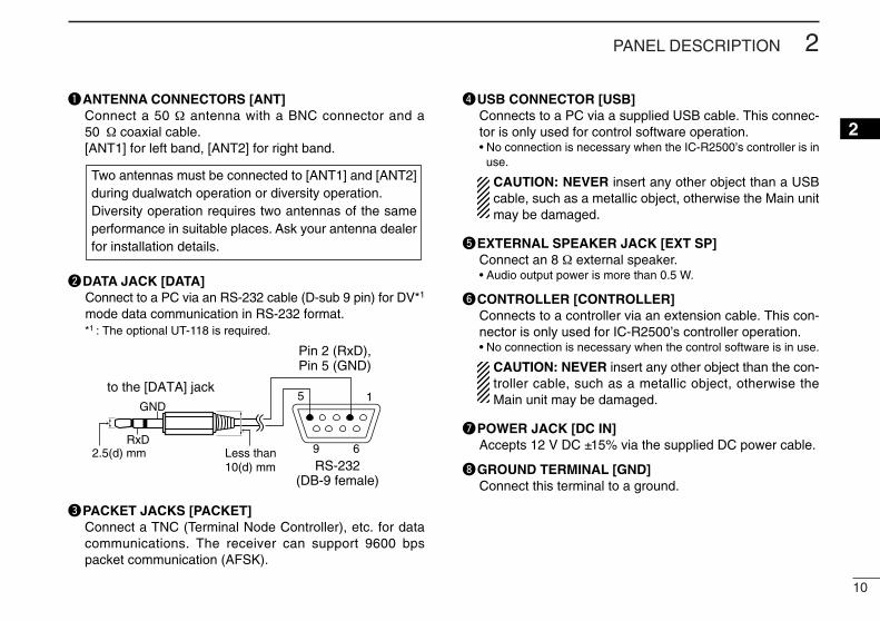
wDATA JACK [DATA]Connect to a PC via an RS-232 cable (D-sub 9 pin) for DV*1
mode data communication in RS-232 format.*1 : The optional UT-118 is required.
ePACKET JACKS [PACKET]Connect a TNC (Terminal Node Controller), etc. for datacommunications. The receiver can support 9600 bpspacket communication (AFSK).
rUSB CONNECTOR [USB]Connects to a PC via a supplied USB cable. This connec-tor is only used for control software operation.• No connection is necessary when the IC-R2500’s controller is in
use.
CAUTION: NEVER insert any other object than a USBcable, such as a metallic object, otherwise the Main unitmay be damaged.
tEXTERNAL SPEAKER JACK [EXT SP]Connect an 8 external speaker.• Audio output power is more than 0.5 W.
yCONTROLLER [CONTROLLER]Connects to a controller via an extension cable. This con-nector is only used for IC-R2500’s controller operation.• No connection is necessary when the control software is in use.
CAUTION: NEVER insert any other object than the con-troller cable, such as a metallic object, otherwise theMain unit may be damaged.
uPOWER JACK [DC IN]Accepts 12 V DC ±15% via the supplied DC power cable.
iGROUND TERMINAL [GND]Connect this terminal to a ground.
Pin 2 (RxD), Pin 5 (GND)
to the [DATA] jack
2.5(d) mm Less than10(d) mm
GND
RxD
15
69
RS-232(DB-9 female)
Two antennas must be connected to [ANT1] and [ANT2]during dualwatch operation or diversity operation.Diversity operation requires two antennas of the sameperformance in suitable places. Ask your antenna dealerfor installation details.

11
SETTING A FREQUENCY3■ PreparationD Turning power ON/OFF
➥ Push [PWR• ] for 1 sec. to turn power ON and OFF.
D MAIN bandThe IC-R2500 can receive signals on both the left and rightbands simultaneously.
➥ Push the desired band’s [MAIN•AGC] or [MAIN•NB] to se-lect the main band.• “Q” indicates the main band.
D VFO and memory modesThe receiver has 2 basic operating modes: VFO mode andmemory mode. Select VFO mode first to set an operating fre-quency.
➥ Push the desired band’s [VFO/MR•S.MW] to select VFOmode.
➥ Push [VFO/MR•S.MW] again to select memory mode.• “!” indicator appears when memory mode is selected.
“!” indicator appears whenmemory mode is selected
[VFO/MR•S.MW]
[MAIN•AGC]
[MAIN•NB]
[PWR• ]
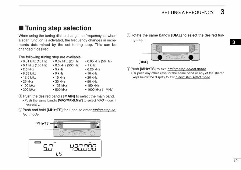
■ Tuning step selectionWhen using the tuning dial to change the frequency, or whena scan function is activated, the frequency changes in incre-ments determined by the set tuning step. This can bechanged if desired.
The following tuning step are available.• 0.01 kHz (10 Hz) • 0.02 kHz (20 Hz) • 0.05 kHz (50 Hz)• 0.1 kHz (100 Hz) • 0.5 kHz (500 Hz) • 1 kHz• 2.5 kHz • 5 kHz • 6.25 kHz• 8.33 kHz • 9 kHz • 10 kHz• 12.5 kHz • 15 kHz • 20 kHz• 25 kHz • 30 kHz • 50 kHz• 100 kHz • 125 kHz • 150 kHz• 200 kHz • 500 kHz • 1000 kHz (1 MHz)
q Push the desired band’s [MAIN] to select the main band.• Push the same band’s [VFO/MR•S.MW] to select VFO mode, if
necessary.
wPush and hold [MHz•TS] for 1 sec. to enter tuning step se-lect mode.
eRotate the same band’s [DIAL] to select the desired tun-ing step.
rPush [MHz•TS] to exit tuning step select mode.• Or push any other keys for the same band or any of the shared
keys below the display to exit tuning step select mode.
[DIAL]
[MHz•TS]
12
3SETTING A FREQUENCY
3

13
3 SETTING A FREQUENCY
■ Using the tuning dialqRotate the desired band’s [DIAL] to set the frequency.
• If VFO mode is not selected, push the same band’s[VFO/MR•S.MW] to select VFO mode.
• The frequency changes in the selected tuning steps. (p. 12)
wTo change the frequency band or tune in 1 MHz (10 MHz)steps, push [MHz•TS], then rotate the band’s [DIAL].
ePush [MHz•TS] to return to the normal display.
■ Receive mode selectionReceive modes are determined by the physical properties ofthe radio signals. The receiver has 6 receive modes: USBLSB, CW, AM, WFM and FM modes. The mode selection isstored independently in each memory channel. Additionally, IC-R2500 has a DV or P25 mode when the op-tional UT-118 or UT-122 units are installed, respectively. InDV or P25 mode, the right band can select AM, FM and WFMmode only.
Typically, AM mode is used for the AM broadcast stations(0.495–1.620 MHz), air band (118–135.995 MHz), and short-wave broadcasts. WFM is used for FM broadcast stations(76–107.9 MHz). WFM mode can be selected on 1300 MHzband or below.
qPush [MODE•SCAN] to enter receive mode select mode.
wRotate main band’s [DIAL] to select the desired mode.
ePush any key for main band to exit receive mode selectmode.
[DIAL]
[MODE•SCAN]While the band selection mode is selected, the digits below 100 kHz disappear.
While 1 MHz tuning step is selected, the 1 MHz digit blinks.
While 10 MHz tuning step is selected, the 10 MHz digit blinks.
Push [VFO/MR•S.MW]
Rotate [DIAL]
14
4BASIC OPERATION
12345678910111213141516
■ ReceivingqSet the audio level for the main band.
➥ Push the desired band’s [MAIN].➥ Push [MONI•T/T-SCAN] to open the squelch.➥ Rotate the main band’s [VOL] to adjust the audio level.➥ Push [MONI•T/T-SCAN] to close the squelch.
wSet the squelch level.➥ Rotate the main band’s [SQL] fully counterclockwise in
advance, then rotate [SQL] clockwise until the noisejust disappears.
eSet the operating frequency in the main band. (pgs. 11–13)• When interference due to strong signals is received, push
[ATT•PRIO] to turn the attenuator function ON. (p. 15)rWhen a signal is received on the set frequency, squelch
opens and the receiver emits audio.• “BUSY” appears and the S-meter shows the relative signal
strength for the received signal.
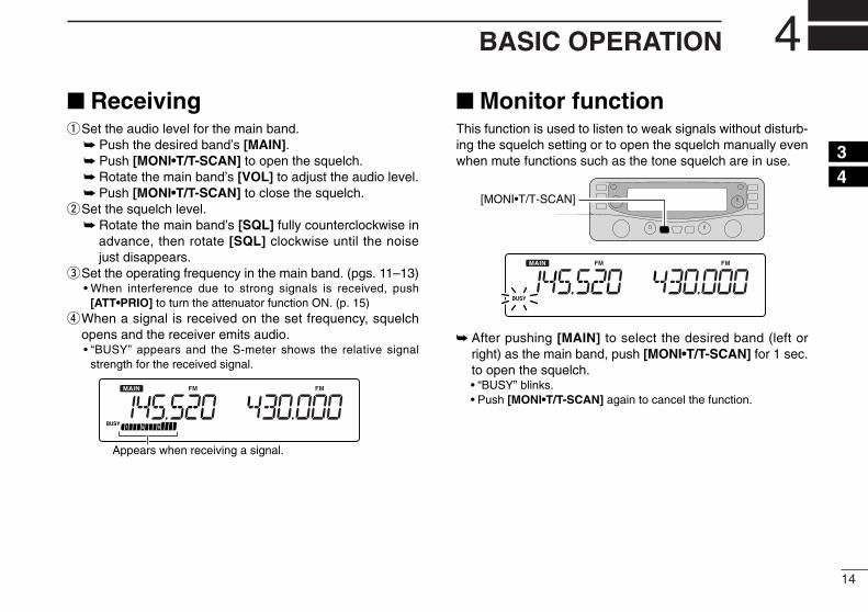
■ Monitor functionThis function is used to listen to weak signals without disturb-ing the squelch setting or to open the squelch manually evenwhen mute functions such as the tone squelch are in use.
➥ After pushing [MAIN] to select the desired band (left orright) as the main band, push [MONI•T/T-SCAN] for 1 sec.to open the squelch.• “BUSY” blinks.• Push [MONI•T/T-SCAN] again to cancel the function.
[MONI•T/T-SCAN]
Appears when receiving a signal.
■ Lock functionTo prevent accidental frequency changes and unintentionalfunction access, use the lock function.
➥ Continue to hold [PWR• ] down for 2 sec. after powerON to turn the lock function ON and OFF.• [MONI•T/T-SCAN] (monitor function only), [VOL], [SQL],
[MAIN•AGC] (main band selection only) and [MAIN•NB] (mainband selection only) can be used while the lock function is inuse.
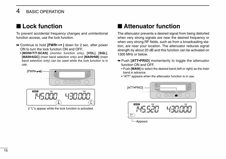
■ Attenuator functionThe attenuator prevents a desired signal from being distortedwhen very strong signals are near the desired frequency orwhen very strong RF fields, such as from a broadcasting sta-tion, are near your location. The attenuator reduces signalstrength by about 20 dB and this function can be activated on1300 MHz or below.
➥ Push [ATT•PRIO] momentarily to toggle the attenuatorfunction ON and OFF.• Push [MAIN] to select the desired band (left or right) as the main
band in advance.• “ATT” appears when the attenuator function is in use.
[ATT•PRIO]
Appears
[PWR• ]
2 “L”s appear while the lock function is activated.
15
4 BASIC OPERATION
16
4BASIC OPERATION
12345678910111213141516
■ NB functionThe NB (noise blanker) function removes pulse-type noisewhen SSB, CW or AM mode is selected.
➥ After pushing [MAIN] to select the desired band (left orright) as the main band, push and hold [MAIN•NB] for 1sec. to toggle the NB function ON and OFF.• “nb-On” or “nb-OF” appears for a moment when the NB function
is turned ON or OFF, respectively.
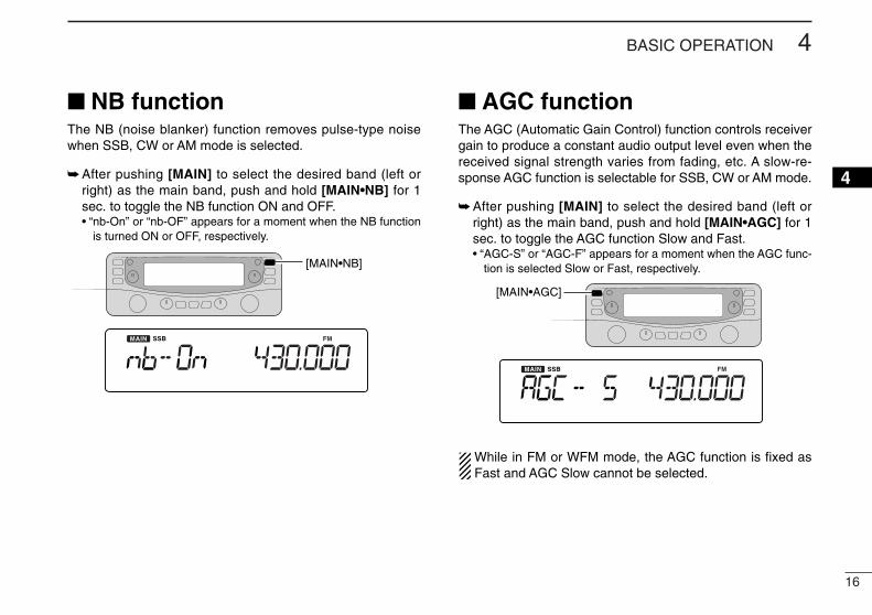
■ AGC functionThe AGC (Automatic Gain Control) function controls receivergain to produce a constant audio output level even when thereceived signal strength varies from fading, etc. A slow-re-sponse AGC function is selectable for SSB, CW or AM mode.
➥ After pushing [MAIN] to select the desired band (left orright) as the main band, push and hold [MAIN•AGC] for 1sec. to toggle the AGC function Slow and Fast.• “AGC-S” or “AGC-F” appears for a moment when the AGC func-
tion is selected Slow or Fast, respectively.
While in FM or WFM mode, the AGC function is fixed asFast and AGC Slow cannot be selected.
[MAIN•AGC]
[MAIN•NB]
17
4 BASIC OPERATION
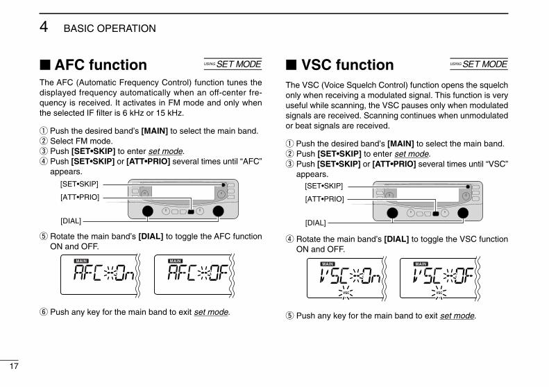
■ AFC function [The AFC (Automatic Frequency Control) function tunes thedisplayed frequency automatically when an off-center fre-quency is received. It activates in FM mode and only whenthe selected IF filter is 6 kHz or 15 kHz.
q Push the desired band’s [MAIN] to select the main band.w Select FM mode.e Push [SET•SKIP] to enter set mode.r Push [SET•SKIP] or [ATT•PRIO] several times until “AFC”
appears.
t Rotate the main band’s [DIAL] to toggle the AFC functionON and OFF.
y Push any key for the main band to exit set mode.
■ VSC function [
The VSC (Voice Squelch Control) function opens the squelchonly when receiving a modulated signal. This function is veryuseful while scanning, the VSC pauses only when modulatedsignals are received. Scanning continues when unmodulatedor beat signals are received.
q Push the desired band’s [MAIN] to select the main band.w Push [SET•SKIP] to enter set mode.e Push [SET•SKIP] or [ATT•PRIO] several times until “VSC”
appears.
r Rotate the main band’s [DIAL] to toggle the VSC functionON and OFF.
t Push any key for the main band to exit set mode.
[SET•SKIP]
[DIAL]
[ATT•PRIO]
[SET•SKIP]
[DIAL]
[ATT•PRIO]
18
4BASIC OPERATION
12345678910111213141516
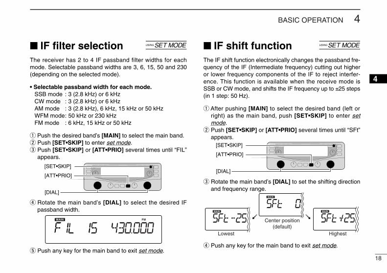
■ IF filter selection [
The receiver has 2 to 4 IF passband filter widths for eachmode. Selectable passband widths are 3, 6, 15, 50 and 230(depending on the selected mode).
• Selectable passband width for each mode.SSB mode : 3 (2.8 kHz) or 6 kHzCW mode : 3 (2.8 kHz) or 6 kHzAM mode : 3 (2.8 kHz), 6 kHz, 15 kHz or 50 kHzWFM mode: 50 kHz or 230 kHzFM mode : 6 kHz, 15 kHz or 50 kHz
q Push the desired band’s [MAIN] to select the main band.w Push [SET•SKIP] to enter set mode.e Push [SET•SKIP] or [ATT•PRIO] several times until “FIL”
appears.
r Rotate the main band’s [DIAL] to select the desired IFpassband width.
t Push any key for the main band to exit set mode.
■ IF shift function [
The IF shift function electronically changes the passband fre-quency of the IF (Intermediate frequency) cutting out higheror lower frequency components of the IF to reject interfer-ence. This function is available when the receive mode isSSB or CW mode, and shifts the IF frequency up to ±25 steps(in 1 step: 50 Hz).
q After pushing [MAIN] to select the desired band (left orright) as the main band, push [SET•SKIP] to enter setmode.
w Push [SET•SKIP] or [ATT•PRIO] several times until “SFt”appears.
e Rotate the main band’s [DIAL] to set the shifting directionand frequency range.
r Push any key for the main band to exit set mode.
Center position(default)
HighestLowest
[SET•SKIP]
[DIAL]
[ATT•PRIO]
[SET•SKIP]
[DIAL]
[ATT•PRIO]
19
4 BASIC OPERATION
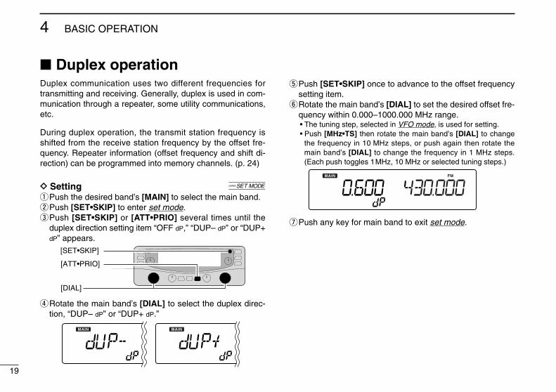
Duplex communication uses two different frequencies fortransmitting and receiving. Generally, duplex is used in com-munication through a repeater, some utility communications,etc.
During duplex operation, the transmit station frequency isshifted from the receive station frequency by the offset fre-quency. Repeater information (offset frequency and shift di-rection) can be programmed into memory channels. (p. 24)
D Setting [qPush the desired band’s [MAIN] to select the main band.wPush [SET•SKIP] to enter set mode.ePush [SET•SKIP] or [ATT•PRIO] several times until the
duplex direction setting item “OFF dP,” “DUP– dP” or “DUP+dP” appears.
rRotate the main band’s [DIAL] to select the duplex direc-tion, “DUP– dP” or “DUP+ dP.”
tPush [SET•SKIP] once to advance to the offset frequencysetting item.
yRotate the main band’s [DIAL] to set the desired offset fre-quency within 0.000–1000.000 MHz range.• The tuning step, selected in VFO mode, is used for setting.• Push [MHz•TS] then rotate the main band’s [DIAL] to change
the frequency in 10 MHz steps, or push again then rotate themain band’s [DIAL] to change the frequency in 1 MHz steps.(Each push toggles 1MHz, 10 MHz or selected tuning steps.)
uPush any key for main band to exit set mode.
[SET•SKIP]
[DIAL]
[ATT•PRIO]
■ Duplex operation
20
4BASIC OPERATION
12345678910111213141516
D OperationqSet the receive station frequency (repeater output frequency).wPush [MONI•T/T-SCAN] to monitor the transmit station fre-
quency (repeater input frequency) directly.
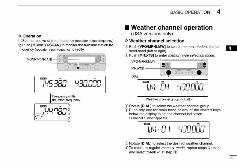
■ Weather channel operation(USA versions only)
D Weather channel selectionq Push [VFO/MR•S.MW] to select memory mode in the de-
sired band (left or right).w Push [MHz•TS] to enter memory type selection mode.
e Rotate [DIAL] to select the weather channel group.r Push any key for main band or any of the shared keys
below the display to set the channel indication.• Channel number appears.
t Rotate [DIAL] to select the desired weather channel.y To return to regular memory mode, repeat steps w to r
and select “bAnk --” at step e.
[DIAL]
[MHz•TS]
[VFO/MR•S.MW]
Weather channel group indicaiton
[MONI•T/T-SCAN]
Frequency shifts the offset frequency
21
4 BASIC OPERATION
D Weather alert functionNOAA broadcast stations transmit weather alert tones beforeimportant weather announcements. When the weather alertfunction is turned ON, the selected weather channel is moni-tored each 5 sec. for the announcement. When the alert sig-nal is detected, the “ALt” and the WX channel are displayedalternately and sounds a beep tone until the receiver controlsare manipulated. The previously selected weather channel ischecked periodically during standby or while scanning.
q Select the desired weather channel.w Turn the weather alert function ON in set mode.
• Push [MAIN] to select the desired band (left or right) as the mainband in advance.
➥ Push [SET•SKIP] to enter set mode.➥ Push [SET•SKIP] or [ATT•PRIO] to select the weather
alert item, then rotate the main band’s [DIAL] to set ON.➥ Push any key for main band to exit set mode.
e Select the desired stand-by condition.• Select VFO or memory channel.• Scan or priority watch operation can also be selected.
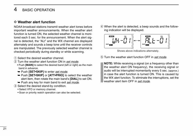
r When the alert is detected, a beep sounds and the follow-ing indication will be displayed.
t Turn the weather alert function OFF in set mode.
NOTE: While receiving a signal (on a frequency other thanthe weather alert ON frequency), the receiving signal oraudio will be interrupted momentarily every 5 sec. (approx.)in case the alert function is turned ON. This is caused bythe WX alert function. To eliminate the interruptions, set theweather alert item OFF in set mode.
Shows above indications alternately.
22
4BASIC OPERATION
12345678910111213141516
■ Single band operationD Single band/Dualwatch operationDualwatch operation monitors two frequencies simultane-ously. The IC-R2500 has two independent receiver circuits:left band, and right band (available frequencies, operating modeand functions are different depending on bands).Single band operation is useful when only one frequency isbeing watched. The right band can be inhibited.
qSelect the left band as the main band.➥ Push [MAIN•AGC] once to select left band, if necessary.
wPush [SET•SKIP] to enter set mode.ePush [SET•SKIP] or [ATT•PRIO] several times to select
“SUb” item.rRotate the left band’s [DIAL] to turn the sub band ON for
dualwatch or OFF for single band operation.
tPush any key for main band to exit set mode.
When the dualwatch operation is in use, IC-R2500 must beconnected to two antennas. ([ANT1] and [ANT2])
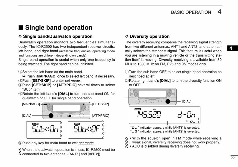
D Diversity operationThe diversity receiving compares the receiving signal strengthfrom two different antennas, ANT1 and ANT2, and automati-cally selects the strongest signal. This feature is useful whenyou are listening in a moving vehicle or the transmitting sta-tion itself is moving. Diversity receiving is available from 50MHz to 1300 MHz on FM, P25 and DV modes only.
qTurn the sub band OFF to select single band operation asdescribed at left.
wRotate right band’s [DIAL] to turn the diversity function ONor OFF.
• With the squelch open in FM mode while receiving aweak signal, diversity receiving does not work properly.
• AGC is disabled during diversity receiving.
[DIAL]
“ ” indicator appears while [ANT1] is selected,“ ” indicator appears while [ANT2] is selected.
[DIAL]
[MAIN•AGC] [SET•SKIP]
[ATT•PRIO]
23
MEMORY OPERATION5■ General descriptionThe receiver has 1100 memory channels including 100 scanedge memory channels (50 pairs) for storage of often-usedfrequencies. And a total of 21 memory banks, A to H, J to R,T, U, W and Y are available for storing groups of frequencies,etc. Up to 100 channels can be assigned to a bank.
D Memory channel contentsThe following information can be programmed into memorychannels:
• Operating frequency (p. 13)• Receive mode (p. 13)• Tuning step (p. 12)• Attenuator ON/OFF (p. 15)• IF filter selection (p. 18)• Duplex direction (DUP+ or DUP–) with an offset fre-
quency (p. 19)• Squelch control system ON/OFF and its frequency or
code (pgs. 39, 41, 43, 45)• Scan skip information (p. 36), etc.
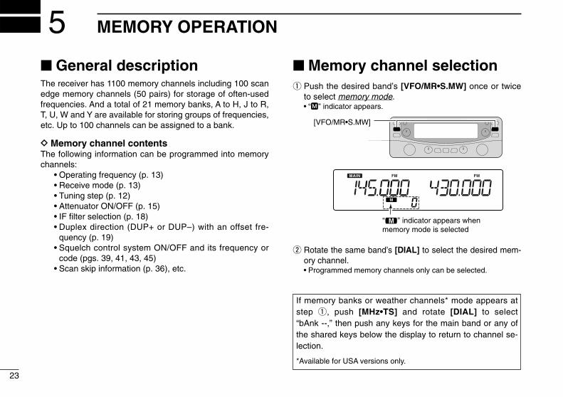
■ Memory channel selectionq Push the desired band’s [VFO/MR•S.MW] once or twice
to select memory mode.• “M” indicator appears.
w Rotate the same band’s [DIAL] to select the desired mem-ory channel.• Programmed memory channels only can be selected.
“!” indicator appears whenmemory mode is selected
[VFO/MR•S.MW]
If memory banks or weather channels* mode appears atstep q, push [MHz•TS] and rotate [DIAL] to select “bAnk --,” then push any keys for the main band or any ofthe shared keys below the display to return to channel se-lection.
*Available for USA versions only.
24
5MEMORY OPERATION
5
■ Programming a memory channel
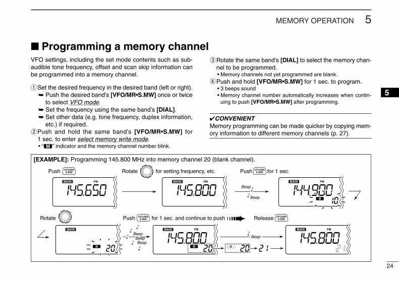
[EXAMPLE]: Programming 145.800 MHz into memory channel 20 (blank channel).
Push Rotate for setting frequency, etc. Push for 1 sec.
Rotate Push for 1 sec. and continue to push ➠
BeepBeepBeepBeep
Beep
Beep
S.MWVFO/MR
S.MWVFO/MR
S.MWVFO/MR
Release S.MWVFO/MR
VFO settings, including the set mode contents such as sub-audible tone frequency, offset and scan skip information canbe programmed into a memory channel.
qSet the desired frequency in the desired band (left or right). ➥ Push the desired band’s [VFO/MR•S.MW] once or twice
to select VFO mode.➥ Set the frequency using the same band’s [DIAL].➥ Set other data (e.g. tone frequency, duplex information,
etc.) if required.wPush and hold the same band’s [VFO/MR•S.MW] for
1 sec. to enter select memory write mode.• “!” indicator and the memory channel number blink.
eRotate the same band’s [DIAL] to select the memory chan-nel to be programmed.• Memory channels not yet programmed are blank.
rPush and hold [VFO/MR•S.MW] for 1 sec. to program.• 3 beeps sound• Memory channel number automatically increases when contin-
uing to push [VFO/MR•S.MW] after programming.
✔CONVENIENTMemory programming can be made quicker by copying mem-ory information to different memory channels (p. 27).
25
5 MEMORY OPERATION
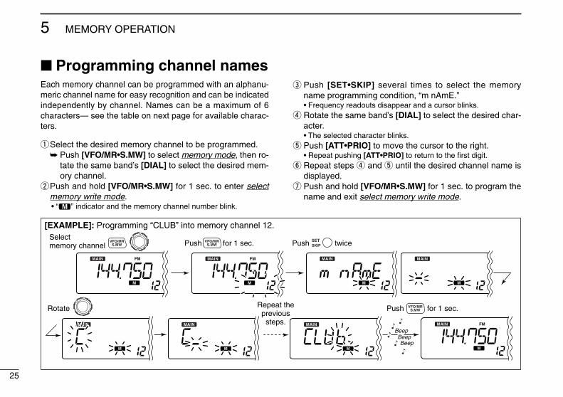
[EXAMPLE]: Programming “CLUB” into memory channel 12.Selectmemory channel Push for 1 sec.
Rotate Push for 1 sec.
BeepBeepBeep
S.MWVFO/MR
S.MWVFO/MR
S.MWVFO/MR Push twiceSET
SKIP
Repeat theprevioussteps.
Each memory channel can be programmed with an alphanu-meric channel name for easy recognition and can be indicatedindependently by channel. Names can be a maximum of 6characters— see the table on next page for available charac-ters.
qSelect the desired memory channel to be programmed.➥ Push [VFO/MR•S.MW] to select memory mode, then ro-
tate the same band’s [DIAL] to select the desired mem-ory channel.
wPush and hold [VFO/MR•S.MW] for 1 sec. to enter selectmemory write mode.• “!” indicator and the memory channel number blink.
e Push [SET•SKIP] several times to select the memoryname programming condition, “m nAmE.”• Frequency readouts disappear and a cursor blinks.
r Rotate the same band’s [DIAL] to select the desired char-acter.• The selected character blinks.
t Push [ATT•PRIO] to move the cursor to the right.• Repeat pushing [ATT•PRIO] to return to the first digit.
y Repeat steps r and t until the desired channel name isdisplayed.
u Push and hold [VFO/MR•S.MW] for 1 sec. to program thename and exit select memory write mode.
■ Programming channel names
26
5MEMORY OPERATION
12345678910111213141516
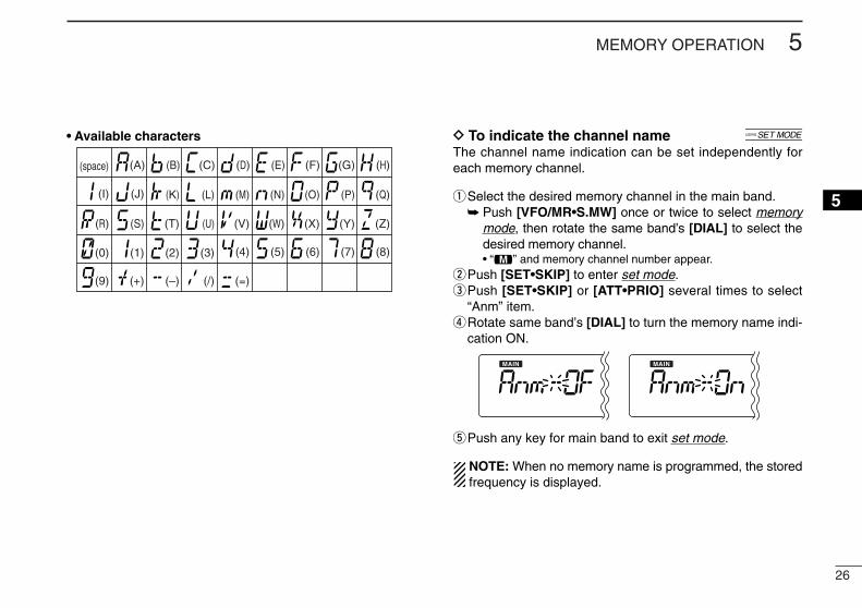
• Available characters D To indicate the channel name [The channel name indication can be set independently foreach memory channel.
qSelect the desired memory channel in the main band.➥ Push [VFO/MR•S.MW] once or twice to select memory
mode, then rotate the same band’s [DIAL] to select thedesired memory channel.• “!” and memory channel number appear.
wPush [SET•SKIP] to enter set mode.ePush [SET•SKIP] or [ATT•PRIO] several times to select
“Anm” item.rRotate same band’s [DIAL] to turn the memory name indi-
cation ON.
tPush any key for main band to exit set mode.
NOTE: When no memory name is programmed, the storedfrequency is displayed.
(1)
(B)
(L)
(V)
(+)
(2)
(C)
(M)
(W)
(–)
(3)
(D)
(N)
(X)
(/)
(4)
(E)
(O)
(Y)
(=)
(5)
(F)
(P)
(Z)
(6)
(G)
(Q)
(space)
(7)
(H)
(R)
(8)
(I)
(S)
(9)
(J)
(T)
(0)
(A)
(K)
(U)
27
5 MEMORY OPERATION
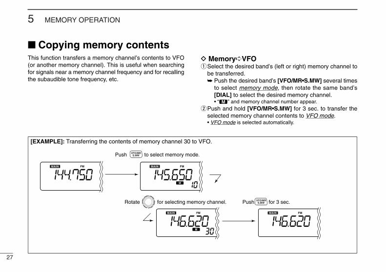
[EXAMPLE]: Transferring the contents of memory channel 30 to VFO.
Push to select memory mode.
Rotate for selecting memory channel. Push for 3 sec.
S.MWVFO/MR
S.MWVFO/MR
This function transfers a memory channel’s contents to VFO(or another memory channel). This is useful when searchingfor signals near a memory channel frequency and for recallingthe subaudible tone frequency, etc.
D Memory➪VFOqSelect the desired band’s (left or right) memory channel to
be transferred.➥ Push the desired band’s [VFO/MR•S.MW] several times
to select memory mode, then rotate the same band’s[DIAL] to select the desired memory channel.• “!” and memory channel number appear.
wPush and hold [VFO/MR•S.MW] for 3 sec. to transfer theselected memory channel contents to VFO mode.• VFO mode is selected automatically.
■ Copying memory contents
28
5MEMORY OPERATION
5
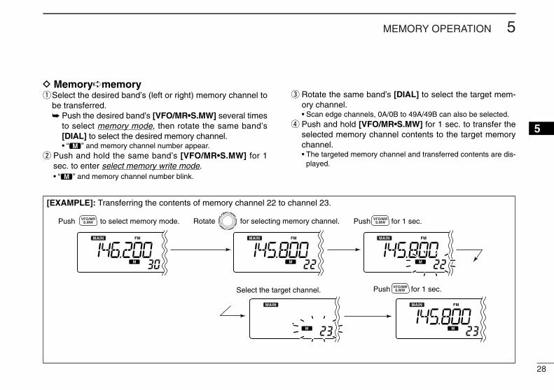
D Memory➪memoryqSelect the desired band’s (left or right) memory channel to
be transferred.➥ Push the desired band’s [VFO/MR•S.MW] several times
to select memory mode, then rotate the same band’s[DIAL] to select the desired memory channel.• “!” and memory channel number appear.
w Push and hold the same band’s [VFO/MR•S.MW] for 1sec. to enter select memory write mode.• “!” and memory channel number blink.
e Rotate the same band’s [DIAL] to select the target mem-ory channel.• Scan edge channels, 0A/0B to 49A/49B can also be selected.
r Push and hold [VFO/MR•S.MW] for 1 sec. to transfer theselected memory channel contents to the target memorychannel.• The targeted memory channel and transferred contents are dis-
played.
[EXAMPLE]: Transferring the contents of memory channel 22 to channel 23.
Push to select memory mode.
Select the target channel.
Rotate for selecting memory channel.
Push for 1 sec.
S.MWVFO/MR
S.MWVFO/MR
Push for 1 sec.S.MWVFO/MR
5 MEMORY OPERATION
29
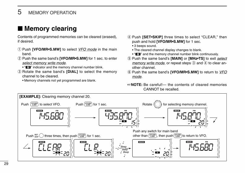
Contents of programmed memories can be cleared (erased),if desired.
q Push [VFO/MR•S.MW] to select VFO mode in the mainband.
w Push the same band’s [VFO/MR•S.MW] for 1 sec. to enterselect memory write mode.• “!” indicator and the memory channel number blink.
e Rotate the same band’s [DIAL] to select the memorychannel to be cleared.• Memory channels not yet programmed are blank.
r Push [SET•SKIP] three times to select “CLEAR,” thenpush and hold [VFO/MR•S.MW] for 1 sec.• 3 beeps sound.• The cleared channel display changes to blank.• “!” and the memory channel number blink continuously.
t Push the same band’s [MAIN] or [MHz•TS] to exit selectmemory write mode, or repeat steps e and r to clear an-other channel.
y Push the same band’s [VFO/MR•S.MW] to return to VFOmode.
☞NOTE: Be careful!— the contents of cleared memoriesCANNOT be recalled.
[EXAMPLE]: Clearing memory channel 20.
Push to select VFO. Rotate for selecting memory channel.Push for 1 sec.S.MWVFO/MR
S.MWVFO/MR
S.MWVFO/MR
Push any switch for main band other than , then push to return to VFO.S.MW
VFO/MRS.MW
VFO/MRPush three times, then push for 1 sec.SETSKIP
BeepBeepBeep
■ Memory clearing
5MEMORY OPERATION
30
5
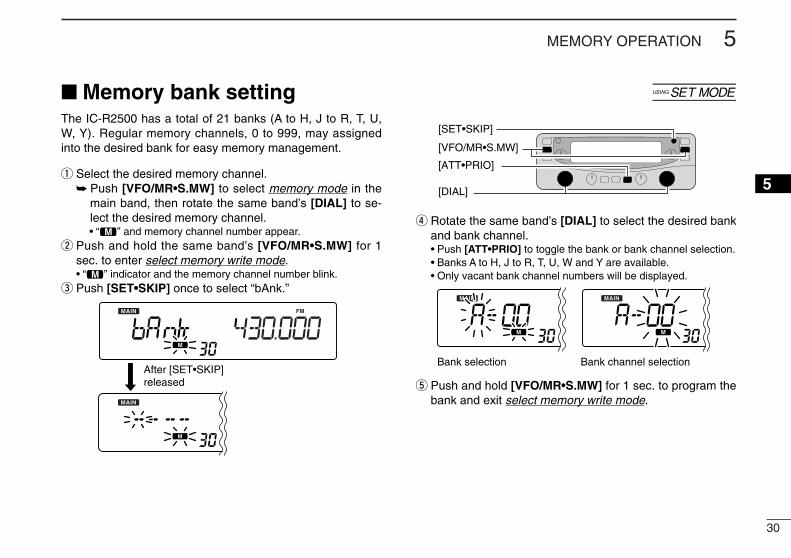
■ Memory bank setting [The IC-R2500 has a total of 21 banks (A to H, J to R, T, U,W, Y). Regular memory channels, 0 to 999, may assignedinto the desired bank for easy memory management.
q Select the desired memory channel.➥ Push [VFO/MR•S.MW] to select memory mode in the
main band, then rotate the same band’s [DIAL] to se-lect the desired memory channel.• “!” and memory channel number appear.
w Push and hold the same band’s [VFO/MR•S.MW] for 1sec. to enter select memory write mode.• “!” indicator and the memory channel number blink.
e Push [SET•SKIP] once to select “bAnk.”
r Rotate the same band’s [DIAL] to select the desired bankand bank channel.• Push [ATT•PRIO] to toggle the bank or bank channel selection.• Banks A to H, J to R, T, U, W and Y are available.• Only vacant bank channel numbers will be displayed.
t Push and hold [VFO/MR•S.MW] for 1 sec. to program thebank and exit select memory write mode.
Bank selection Bank channel selectionAfter [SET•SKIP]released
[SET•SKIP]
[DIAL]
[ATT•PRIO]
[VFO/MR•S.MW]
31
5 MEMORY OPERATION
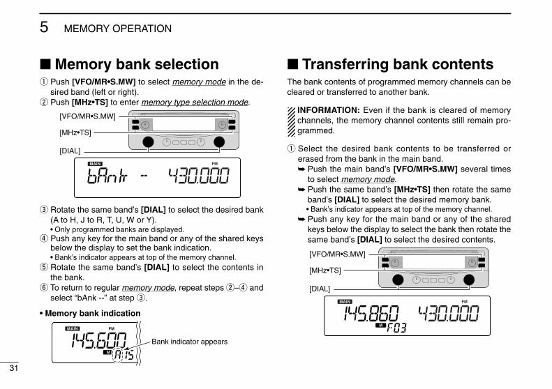
■ Memory bank selectionq Push [VFO/MR•S.MW] to select memory mode in the de-
sired band (left or right).w Push [MHz•TS] to enter memory type selection mode.
e Rotate the same band’s [DIAL] to select the desired bank(A to H, J to R, T, U, W or Y).• Only programmed banks are displayed.
r Push any key for the main band or any of the shared keysbelow the display to set the bank indication.• Bank’s indicator appears at top of the memory channel.
t Rotate the same band’s [DIAL] to select the contents inthe bank.
y To return to regular memory mode, repeat steps w–r andselect “bAnk --” at step e.
• Memory bank indication
■ Transferring bank contentsThe bank contents of programmed memory channels can becleared or transferred to another bank.
INFORMATION: Even if the bank is cleared of memorychannels, the memory channel contents still remain pro-grammed.
q Select the desired bank contents to be transferred orerased from the bank in the main band.➥ Push the main band’s [VFO/MR•S.MW] several times
to select memory mode.➥ Push the same band’s [MHz•TS] then rotate the same
band’s [DIAL] to select the desired memory bank.• Bank’s indicator appears at top of the memory channel.
➥ Push any key for the main band or any of the sharedkeys below the display to select the bank then rotate thesame band’s [DIAL] to select the desired contents.
[DIAL]
[MHz•TS]
[VFO/MR•S.MW]
Bank indicator appears
[DIAL]
[MHz•TS]
[VFO/MR•S.MW]
32
5MEMORY OPERATION
5
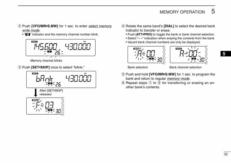
w Push [VFO/MR•S.MW] for 1 sec. to enter select memorywrite mode.• “!” indicator and the memory channel number blink.
e Push [SET•SKIP] once to select “bAnk.”
r Rotate the same band’s [DIAL] to select the desired bankindicator to transfer or erase.• Push [ATT•PRIO] to toggle the bank or bank channel selection.• Select “– –” indication when erasing the contents from the bank.• Vacant bank channel numbers are only be displayed.
t Push and hold [VFO/MR•S.MW] for 1 sec. to program thebank and return to regular memory mode.
y Repeat steps q to t for transferring or erasing an an-other bank’s contents.
Bank selection Bank channel selection
After [SET•SKIP]released
Memory channel blinks
33
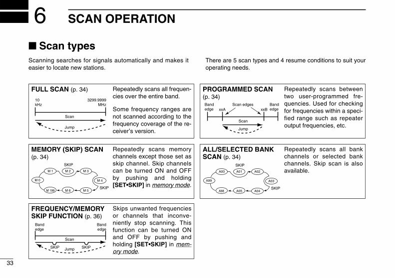
SCAN OPERATION6■ Scan typesScanning searches for signals automatically and makes iteasier to locate new stations.
There are 5 scan types and 4 resume conditions to suit youroperating needs.
FULL SCAN (p. 34) Repeatedly scans all frequen-cies over the entire band.
Some frequency ranges arenot scanned according to thefrequency coverage of the re-ceiver’s version.
10kHz
3299.9999MHz
Scan
Jump
ALL/SELECTED BANKSCAN (p. 34)
Repeatedly scans all bankchannels or selected bankchannels. Skip scan is alsoavailable.
SKIP
SKIP
A99 A03
A00 A01 A02
A04A98 A05
PROGRAMMED SCAN(p. 34)
Repeatedly scans betweentwo user-programmed fre-quencies. Used for checkingfor frequencies within a speci-fied range such as repeateroutput frequencies, etc.
Bandedge xxA xxB
Bandedge
Scan edges
Scan
Jump
MEMORY (SKIP) SCAN(p. 34)
Repeatedly scans memorychannels except those set asskip channel. Skip channelscan be turned ON and OFFby pushing and holding[SET•SKIP] in memory mode.
SKIP
SKIP
M 0 M 4
M 1 M 2 M 3
M 5M 199 M 6
FREQUENCY/MEMORYSKIP FUNCTION (p. 36)
Skips unwanted frequenciesor channels that inconve-niently stop scanning. Thisfunction can be turned ONand OFF by pushing andholding [SET•SKIP] in mem-ory mode.
Bandedge
Bandedge
Scan
SKIP SKIPJump
34
6SCAN OPERATION
12345678910111213141516
■ Scan start/stopD PreparationScan resume condition (p. 37); program scan edges (p. 35);program two or more memory channels (p. 24); set skip set-tings (p. 36), if desired.
D OperationqPush [VFO/MR•S.MW] once or twice to select VFO mode
for full/programmed scan; or to select memory mode formemory/bank scan.• Select the desired bank in memory type selection mode for bank
scan.wSet the squelch level to the point where noise is just muted.ePush and hold [MODE•SCAN] for 1 sec. to start the scan.
• To change the scanning direction, rotate the main band’s [DIAL].• The memory channel readout blinks the scan type as below.
r Push [SET•SKIP] (or [ATT•PRIO]) to select full and pro-grammed scan (P00 to P49), if VFO is selected in step q.
t To stop the scan, push [MODE•SCAN].
About the scanning steps: The selected tuning step ineach frequency band (in VFO mode) is used during scan.
The bank-link setting can be changed in set mode. See(p. 56) for details.
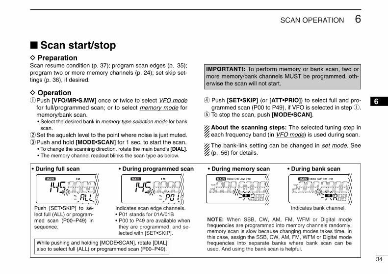
• During full scan • During programmed scan • During memory scan • During bank scan
Indicates scan edge channels.• P01 stands for 01A/01B• P00 to P49 are available when
they are programmed, and se-lected with [SET•SKIP].
Indicates bank channel.Push [SET•SKIP] to se-lect full (ALL) or program-med scan (P00–P49) in sequence.
While pushing and holding [MODE•SCAN], rotate [DIAL] also to select full (ALL) or programmed scan (P00–P49).
NOTE: When SSB, CW, AM, FM, WFM or Digital mode frequencies are programmed into memory channels randomly, memory scan is slow because changing modes takes time. In this case, assign the SSB, CW, AM, FM, WFM or Digital mode frequencies into separate banks where bank scan can be used. And using the bank scan is helpful.
IMPORTANT!: To perform memory or bank scan, two ormore memory/bank channels MUST be programmed, oth-erwise the scan will not start.
35
6 SCAN OPERATION
Scan edges can be programmed in the same manner asmemory channels. Scan edges are programmed into scanedges, 0A/0B to 49A/49B, in memory channels.
q Push the desired band’s [VFO/MR•S.MW] once or twiceto select VFO mode.
w Set the edge frequency of the desired frequency range:➥ Set the frequency using the same band’s [DIAL].➥ Set other data (e.g. tone squelch, etc.), if desired.
e Push and hold the same band’s [VFO/MR•S.MW] for1 sec. to enter select memory write mode.• “!” indicator and the memory channel number blink.
r Rotate the same band’s [DIAL] to select one of scan edgechannel, 0A to 49A.
t Push and hold [VFO/MR•S.MW] for 1 sec. to program.• 3 beeps sound and VFO mode is automatically selected.• Scan edge 0B to 49B is automatically selected when continuing
to hold [VFO/MR•S.MW] after programming.y To program a frequency for the other pair of scan edges,
0B to 49B, repeat steps w to r.• If the same frequency is programmed into a pair of scan edges,
programmed scan will not function.
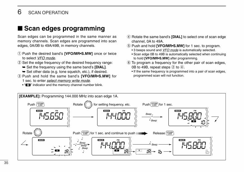
[EXAMPLE]: Programming 144.000 MHz into scan edge 1A.
Push Rotate for setting frequency, etc. Push for 1 sec.
Rotate Push for 1 sec. and continue to push ➠
BeepBeepBeepBeep
Beep
Beep
S.MWVFO/MR
S.MWVFO/MR
S.MWVFO/MR
Release S.MWVFO/MR
■ Scan edges programming
36
6SCAN OPERATION
6
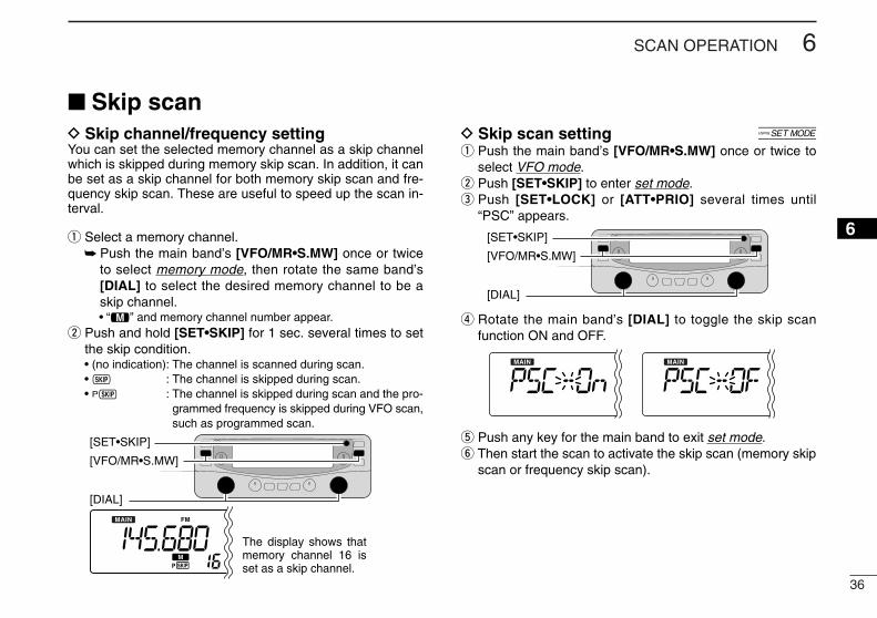
D Skip channel/frequency settingYou can set the selected memory channel as a skip channelwhich is skipped during memory skip scan. In addition, it canbe set as a skip channel for both memory skip scan and fre-quency skip scan. These are useful to speed up the scan in-terval.
q Select a memory channel.➥ Push the main band’s [VFO/MR•S.MW] once or twice
to select memory mode, then rotate the same band’s[DIAL] to select the desired memory channel to be askip channel.• “!” and memory channel number appear.
w Push and hold [SET•SKIP] for 1 sec. several times to setthe skip condition.• (no indication): The channel is scanned during scan.• ~ : The channel is skipped during scan.• P~ : The channel is skipped during scan and the pro-
grammed frequency is skipped during VFO scan,such as programmed scan.
D Skip scan setting [q Push the main band’s [VFO/MR•S.MW] once or twice to
select VFO mode.w Push [SET•SKIP] to enter set mode.e Push [SET•LOCK] or [ATT•PRIO] several times until
“PSC” appears.
r Rotate the main band’s [DIAL] to toggle the skip scanfunction ON and OFF.
t Push any key for the main band to exit set mode.y Then start the scan to activate the skip scan (memory skip
scan or frequency skip scan).
[DIAL]
[VFO/MR•S.MW]
[SET•SKIP]
[DIAL]
[VFO/MR•S.MW]
The display shows that memory channel 16 is set as a skip channel.
[SET•SKIP]
■ Skip scan
37
6 SCAN OPERATION
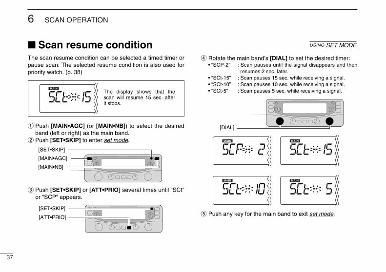
The scan resume condition can be selected a timed timer orpause scan. The selected resume condition is also used forpriority watch. (p. 38)
q Push [MAIN•AGC] (or [MAIN•NB]) to select the desiredband (left or right) as the main band.
w Push [SET•SKIP] to enter set mode.
e Push [SET•SKIP] or [ATT•PRIO] several times until “SCt”or “SCP” appears.
r Rotate the main band’s [DIAL] to set the desired timer:• “SCP-2” : Scan pauses until the signal disappears and then
resumes 2 sec. later.• “SCt-15” : Scan pauses 15 sec. while receiving a signal.• “SCt-10” : Scan pauses 10 sec. while receiving a signal.• “SCt-5” : Scan pauses 5 sec. while receiving a signal.
t Push any key for the main band to exit set mode.
[DIAL]
[ATT•PRIO]
[SET•SKIP]
[MAIN•AGC]
[MAIN•NB]
[SET•SKIP]
The display shows that the scan will resume 15 sec. after it stops.
■ Scan resume condition USING SET MODE
38
7PRIORITY WATCH
12345678910111213141516
■ Priority watch typesPriority watch checks for signals on the frequency every5 sec. while operating on a VFO frequency or scanning. Thereceiver has two priority watch types to suit your needs.
The watch resumes according to the selected scan resumecondition. See (p. 37) for details.
NOTE: If the pocket beep function is activated, the receiverautomatically selects the tone/DTCS squelch functionwhen priority watch starts.
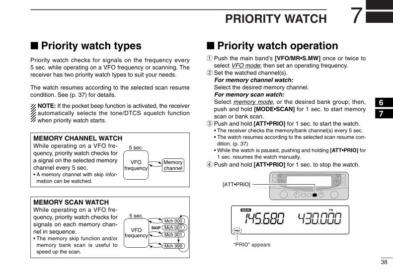
■ Priority watch operationq Push the main band’s [VFO/MR•S.MW] once or twice to
select VFO mode; then set an operating frequency.w Set the watched channel(s).
For memory channel watch:Select the desired memory channel.For memory scan watch:Select memory mode, or the desired bank group; then,push and hold [MODE•SCAN] for 1 sec. to start memoryscan or bank scan.
e Push and hold [ATT•PRIO] for 1 sec. to start the watch.• The receiver checks the memory/bank channel(s) every 5 sec.• The watch resumes according to the selected scan resume con-
dition. (p. 37)• While the watch is paused, pushing and holding [ATT•PRIO] for
1 sec. resumes the watch manually.
r Push and hold [ATT•PRIO] for 1 sec. to stop the watch.
[ATT•PRIO]
“PRIO” appears
MEMORY CHANNEL WATCHWhile operating on a VFO fre-quency, priority watch checks fora signal on the selected memorychannel every 5 sec.• A memory channel with skip infor-
mation can be watched.
5 sec.
VFOfrequency
Memorychannel
MEMORY SCAN WATCHWhile operating on a VFO fre-quency, priority watch checks forsignals on each memory chan-nel in sequence.• The memory skip function and/or
memory bank scan is useful tospeed up the scan.
5 sec.
VFOfrequency
SKIP
Mch 000Mch 001
Mch 001
Mch 999
39
POCKET BEEP AND TONE SQUELCH8
This function uses subaudible tones for calling and can beused as a “common pager” to inform you that someone hascalled while you were away from the receiver.
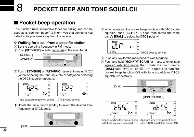
D Waiting for a call from a specific stationq Set the operating frequency in FM mode.w Push [SET•SKIP] to enter set mode in the main band.
e Push [SET•SKIP] or [ATT•PRIO] several times until “Ct”(when selecting the tone squelch) or “dt”(when selectingthe DTCS squelch) appears.
r Rotate the main band’s [DIAL] to select the desired tonefrequency or DTCS code.
t When operating the pocket beep function with DTCS codesquelch, push [SET•SKIP] once then rotate the mainband’s [DIAL] to select the DTCS polarity.
y Push any key for the main band to exit set mode.u Push and hold [MONI•T/T-SCAN] for 1 sec. to enter tone
squelch selection mode, then rotate the main band’s[DIAL] until “S ” or “ S” appears to turn thepocket beep function ON with tone squelch or DTCSsquelch, respectively.
[MONI•T/T-SCAN]
[DIAL]
Appears when the pocket beepwith tone squelch is turned ON.
Appears when the pocket beepwith DTCS squelch is turned ON.
DTCS polarity setting
[DIAL]
Tone squelch frequency setting DTCS code setting
[ATT•PRIO]
[SET•SKIP]
■ Pocket beep operation
40
8POCKET BEEP AND TONE SQUELCH
12345678910111213141516
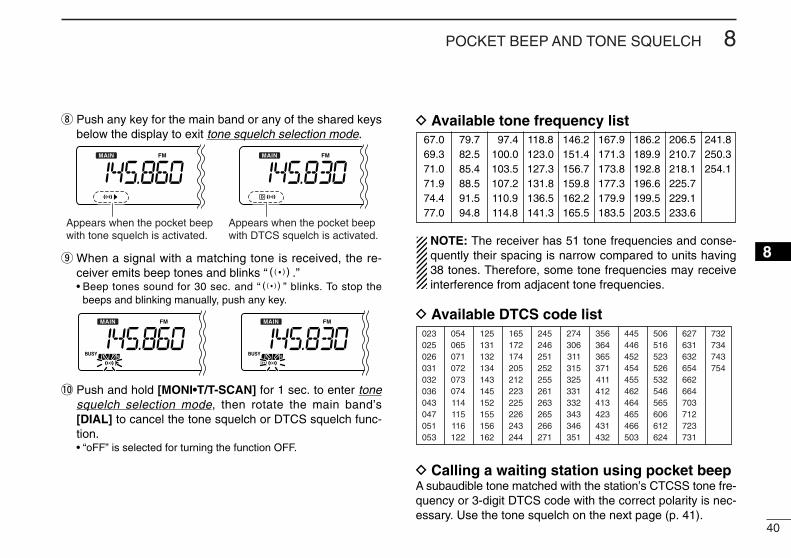
i Push any key for the main band or any of the shared keysbelow the display to exit tone squelch selection mode.
o When a signal with a matching tone is received, the re-ceiver emits beep tones and blinks “S.”• Beep tones sound for 30 sec. and “S” blinks. To stop the
beeps and blinking manually, push any key.
!0 Push and hold [MONI•T/T-SCAN] for 1 sec. to enter tonesquelch selection mode, then rotate the main band’s[DIAL] to cancel the tone squelch or DTCS squelch func-tion.• “oFF” is selected for turning the function OFF.
D Available tone frequency list
NOTE: The receiver has 51 tone frequencies and conse-quently their spacing is narrow compared to units having38 tones. Therefore, some tone frequencies may receiveinterference from adjacent tone frequencies.
D Available DTCS code list
D Calling a waiting station using pocket beepA subaudible tone matched with the station’s CTCSS tone fre-quency or 3-digit DTCS code with the correct polarity is nec-essary. Use the tone squelch on the next page (p. 41).
023025026031032036043047051053
125131132134143145152155156162
245246251252255261263265266271
356364365371411412413423431432
506516523526532546565606612624
054065071072073074114115116122
165172174205212223225226243244
274306311315325331332343346351
445446452454455462464465466503
627631632654662664703712723731
732734743754
Appears when the pocket beepwith tone squelch is activated.
Appears when the pocket beepwith DTCS squelch is activated.
67.069.371.071.974.477.0
79.782.585.488.591.594.8
097.4100.0103.5107.2110.9114.8
118.8123.0127.3131.8136.5141.3
146.2151.4156.7159.8162.2165.5
167.9171.3173.8177.3179.9183.5
186.2189.9192.8196.6199.5203.5
206.5210.7218.1225.7229.1233.6
241.8250.3254.1
41
8 POCKET BEEP AND TONE SQUELCH
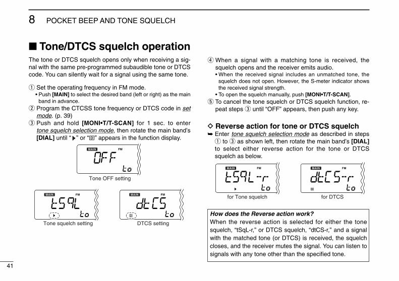
The tone or DTCS squelch opens only when receiving a sig-nal with the same pre-programmed subaudible tone or DTCScode. You can silently wait for a signal using the same tone.
q Set the operating frequency in FM mode.• Push [MAIN] to select the desired band (left or right) as the main
band in advance.w Program the CTCSS tone frequency or DTCS code in set
mode. (p. 39)e Push and hold [MONI•T/T-SCAN] for 1 sec. to enter
tone squelch selection mode, then rotate the main band’s[DIAL] until “ ” or “ ” appears in the function display.
r When a signal with a matching tone is received, thesquelch opens and the receiver emits audio.• When the received signal includes an unmatched tone, the
squelch does not open. However, the S-meter indicator showsthe received signal strength.
• To open the squelch manually, push [MONI•T/T-SCAN].t To cancel the tone squelch or DTCS squelch function, re-
peat steps e until “OFF” appears, then push any key.
D Reverse action for tone or DTCS squelch➥ Enter tone squelch selection mode as described in steps
q to e as shown left, then rotate the main band’s [DIAL]to select either reverse action for the tone or DTCSsquelch as below.
for DTCSfor Tone squelch
Tone OFF setting
DTCS settingTone squelch setting
■ Tone/DTCS squelch operation
How does the Reverse action work?When the reverse action is selected for either the tonesquelch, “tSqL-r,” or DTCS squelch, “dtCS-r,” and a signalwith the matched tone (or DTCS) is received, the squelchcloses, and the receiver mutes the signal. You can listen tosignals with any tone other than the specified tone.
42
8POCKET BEEP AND TONE SQUELCH
8
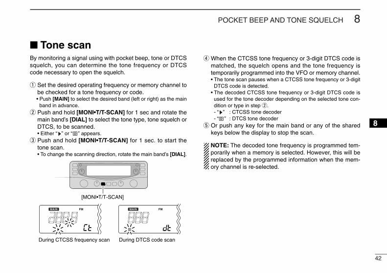
■ Tone scanBy monitoring a signal using with pocket beep, tone or DTCSsquelch, you can determine the tone frequency or DTCScode necessary to open the squelch.
q Set the desired operating frequency or memory channel tobe checked for a tone frequency or code.• Push [MAIN] to select the desired band (left or right) as the main
band in advance.w Push and hold [MONI•T/T-SCAN] for 1 sec and rotate the
main band’s [DIAL] to select the tone type, tone squelch orDTCS, to be scanned.• Either “ ” or “ ” appears.
e Push and hold [MONI•T/T-SCAN] for 1 sec. to start thetone scan.• To change the scanning direction, rotate the main band’s [DIAL].
r When the CTCSS tone frequency or 3-digit DTCS code ismatched, the squelch opens and the tone frequency istemporarily programmed into the VFO or memory channel.• The tone scan pauses when a CTCSS tone frequency or 3-digit
DTCS code is detected.• The decoded CTCSS tone frequency or 3-digit DTCS code is
used for the tone decoder depending on the selected tone con-dition or type in step w.- “ ” : CTCSS tone decoder- “ ” : DTCS tone decoder
t Or push any key for the main band or any of the sharedkeys below the display to stop the scan.
NOTE: The decoded tone frequency is programmed tem-porarily when a memory is selected. However, this will bereplaced by the programmed information when the mem-ory channel is re-selected.
[MONI•T/T-SCAN]
During CTCSS frequency scan During DTCS code scan
43
DIGITAL MODE OPERATION9■ Digital mode operationThe IC-R2500 can operate in DV*1 mode or P25*2 modewhen the optional UT-118 or UT-122 is installed.*1: The optional UT-118 is required.*2: The optional UT-122 is required.
Some versions come with the UT-122 installed.
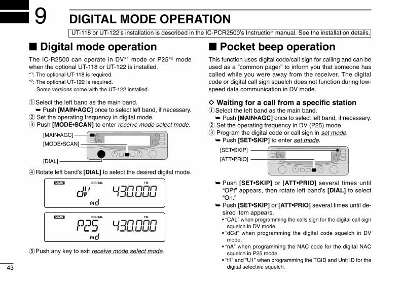
qSelect the left band as the main band.➥ Push [MAIN•AGC] once to select left band, if necessary.
w Set the operating frequency in digital mode.e Push [MODE•SCAN] to enter receive mode select mode.
rRotate left band’s [DIAL] to select the desired digital mode.
tPush any key to exit receive mode select mode.
■ Pocket beep operationThis function uses digital code/call sign for calling and can beused as a “common pager” to inform you that someone hascalled while you were away from the receiver. The digitalcode or digital call sign squelch does not function during low-speed data communication in DV mode.
D Waiting for a call from a specific stationqSelect the left band as the main band.
➥ Push [MAIN•AGC] once to select left band, if necessary.w Set the operating frequency in DV (P25) mode.e Program the digital code or call sign in set mode.
➥ Push [SET•SKIP] to enter set mode.
➥ Push [SET•SKIP] or [ATT•PRIO] several times until“OPt” appears, then rotate left band’s [DIAL] to select“On.”
➥ Push [SET•SKIP] or [ATT•PRIO] several times until de-sired item appears.• “CAL” when programming the calls sign for the digital call sign
squelch in DV mode.• “dCd” when programming the digital code squelch in DV
mode.• “nA” when programming the NAC code for the digital NAC
squelch in P25 mode.• “t1” and “U1” when programming the TGID and Unit ID for the
digital selective squelch.
[ATT•PRIO]
[SET•SKIP]
[DIAL]
[MAIN•AGC]
[MODE•SCAN]
UT-118 or UT-122’s installation is described in the IC-PCR2500’s Instruction manual. See the installation details.
44
9DIGITAL MODE OPERATION
12345678910111213141516
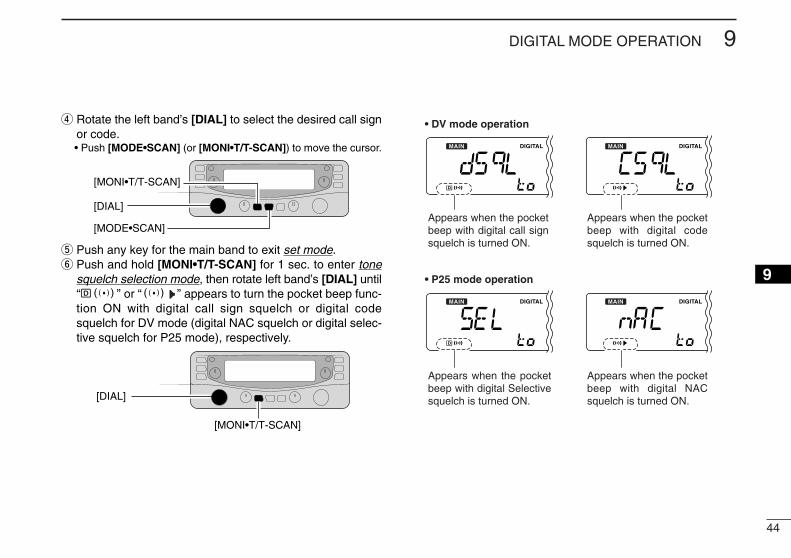
r Rotate the left band’s [DIAL] to select the desired call signor code.• Push [MODE•SCAN] (or [MONI•T/T-SCAN]) to move the cursor.
t Push any key for the main band to exit set mode.y Push and hold [MONI•T/T-SCAN] for 1 sec. to enter tone
squelch selection mode, then rotate left band’s [DIAL] until“ S” or “S ” appears to turn the pocket beep func-tion ON with digital call sign squelch or digital codesquelch for DV mode (digital NAC squelch or digital selec-tive squelch for P25 mode), respectively.
• DV mode operation
Appears when the pocket beep with digital call sign squelch is turned ON.
Appears when the pocket beep with digital code squelch is turned ON.
• P25 mode operation
Appears when the pocket beep with digital Selective squelch is turned ON.
Appears when the pocket beep with digital NAC squelch is turned ON.
[MONI•T/T-SCAN]
[DIAL]
[DIAL]
[MODE•SCAN]
[MONI•T/T-SCAN]
45
9 DIGITAL MODE OPERATION
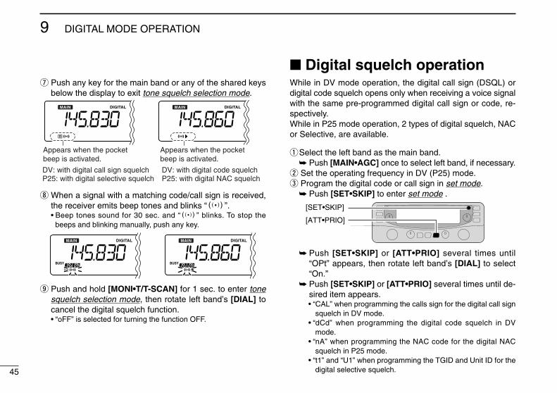
u Push any key for the main band or any of the shared keysbelow the display to exit tone squelch selection mode.
i When a signal with a matching code/call sign is received,the receiver emits beep tones and blinks “S”.• Beep tones sound for 30 sec. and “S” blinks. To stop the
beeps and blinking manually, push any key.
o Push and hold [MONI•T/T-SCAN] for 1 sec. to enter tonesquelch selection mode, then rotate left band’s [DIAL] tocancel the digital squelch function.• “oFF” is selected for turning the function OFF.
■ Digital squelch operationWhile in DV mode operation, the digital call sign (DSQL) ordigital code squelch opens only when receiving a voice signalwith the same pre-programmed digital call sign or code, re-spectively.While in P25 mode operation, 2 types of digital squelch, NACor Selective, are available.
qSelect the left band as the main band.➥ Push [MAIN•AGC] once to select left band, if necessary.
w Set the operating frequency in DV (P25) mode.e Program the digital code or call sign in set mode.
➥ Push [SET•SKIP] to enter set mode .
➥ Push [SET•SKIP] or [ATT•PRIO] several times until“OPt” appears, then rotate left band’s [DIAL] to select“On.”
➥ Push [SET•SKIP] or [ATT•PRIO] several times until de-sired item appears.• “CAL” when programming the calls sign for the digital call sign
squelch in DV mode.• “dCd” when programming the digital code squelch in DV
mode.• “nA” when programming the NAC code for the digital NAC
squelch in P25 mode.• “t1” and “U1” when programming the TGID and Unit ID for the
digital selective squelch.
[ATT•PRIO]
[SET•SKIP]
Appears when the pocket beep is activated.
Appears when the pocket beep is activated.
DV: with digital code squelchP25: with digital NAC squelch
DV: with digital call sign squelchP25: with digital selective squelch
46
9DIGITAL MODE OPERATION
12345678910111213141516
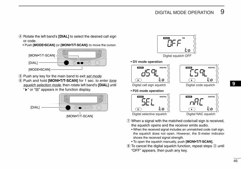
r Rotate the left band’s [DIAL] to select the desired call signor code.• Push [MODE•SCAN] (or [MONI•T/T-SCAN]) to move the cursor.
t Push any key for the main band to exit set mode.y Push and hold [MONI•T/T-SCAN] for 1 sec. to enter tone
squelch selection mode, then rotate left band’s [DIAL] until“ ” or “ ” appears in the function display.
u When a signal with the matched code/call sign is received,the squelch opens and the receiver emits audio.• When the received signal includes an unmatched code /call sign,
the squelch does not open. However, the S-meter indicatorshows the received signal strength.
• To open the squelch manually, push [MONI•T/T-SCAN].i To cancel the digital squelch function, repeat steps e until
“OFF” appears, then push any key.
• DV mode operation
• P25 mode operation
Digital squelch OFF
Digital NAC squelchDigital selective squelch
Digital code squelchDigital call sign squelch
[MONI•T/T-SCAN]
[DIAL]
[DIAL]
[MODE•SCAN]
[MONI•T/T-SCAN]

47
9 DIGITAL MODE OPERATION
Sets your own call sign for digital call sign squelch operation.Up to 8 characters are programmable.
q Push [SET•SKIP] to enter set mode.w Push [SET•SKIP] or [ATT•PRIO] several times until “OPt”
appears, then rotate main band’s [DIAL] to select “On.”
e Push [SET•SKIP] or [ATT•PRIO] several times until “CAL”appears.• The 1st digit blinks.
r Rotate main band’s [DIAL] to select the desired characteror code.• Push [MODE•SCAN] or [MONI•T/T-SCAN] to move the cursor
to right or left, respectively.t Push [MODE•SCAN] to select 2nd digit, then rotate main
band’s [DIAL] to select the desired character or code.• 2nd digit blinks (1st digit stop blinking).• Repeat this step for programming your own call sign.
y Push any key for the main band to exit set mode.
[DIAL]
[VFO/MR•S.MW]
[SET•SKIP]
■ Call sign programming (for DV mode) [
If the wrong call sign or code is programmed, the digitalsquelch will not open. Please make sure of the correct callsign or code before programming.
48
9DIGITAL MODE OPERATION
12345678910111213141516
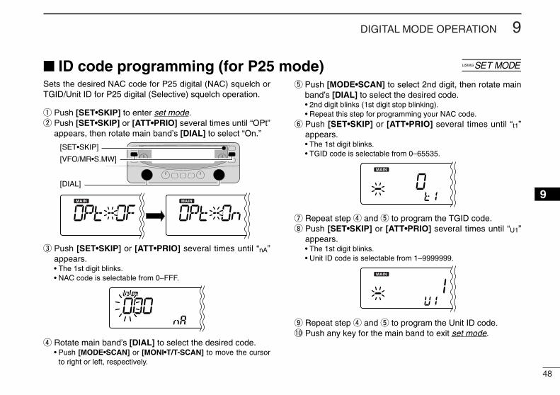
Sets the desired NAC code for P25 digital (NAC) squelch orTGID/Unit ID for P25 digital (Selective) squelch operation.
q Push [SET•SKIP] to enter set mode.w Push [SET•SKIP] or [ATT•PRIO] several times until “OPt”
appears, then rotate main band’s [DIAL] to select “On.”
e Push [SET•SKIP] or [ATT•PRIO] several times until “nA”appears.• The 1st digit blinks.• NAC code is selectable from 0–FFF.
r Rotate main band’s [DIAL] to select the desired code.• Push [MODE•SCAN] or [MONI•T/T-SCAN] to move the cursor
to right or left, respectively.
t Push [MODE•SCAN] to select 2nd digit, then rotate mainband’s [DIAL] to select the desired code.• 2nd digit blinks (1st digit stop blinking).• Repeat this step for programming your NAC code.
y Push [SET•SKIP] or [ATT•PRIO] several times until “t1”appears.• The 1st digit blinks.• TGID code is selectable from 0–65535.
u Repeat step r and t to program the TGID code.i Push [SET•SKIP] or [ATT•PRIO] several times until “U1”
appears.• The 1st digit blinks.• Unit ID code is selectable from 1–9999999.
o Repeat step r and t to program the Unit ID code.!0 Push any key for the main band to exit set mode.
[DIAL]
[VFO/MR•S.MW]
[SET•SKIP]
■ ID code programming (for P25 mode) [
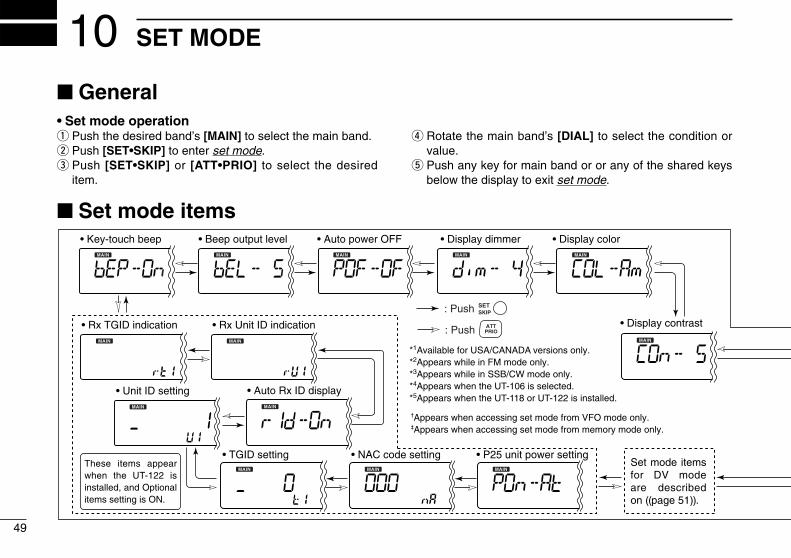
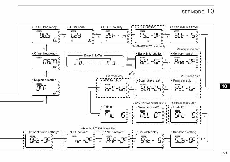
• Display dimmer• Auto power OFF• Key-touch beep • Beep output level • Display color
• Display contrast• Rx TGID indication • Rx Unit ID indication
• Auto Rx ID display• Unit ID setting
• TGID setting • NAC code setting • P25 unit power setting
†Appears when accessing set mode from VFO mode only.‡Appears when accessing set mode from memory mode only.
*1Available for USA/CANADA versions only.*2Appears while in FM mode only.*3Appears while in SSB/CW mode only.*4Appears when the UT-106 is selected.*5Appears when the UT-118 or UT-122 is installed.
: Push
: Push
SETSKIP
ATTPRIO
These items appear when the UT-122 is installed, and Optional items setting is ON.
Set mode items for DV mode are described on ((page 51)).
■ General• Set mode operationq Push the desired band’s [MAIN] to select the main band.w Push [SET•SKIP] to enter set mode.e Push [SET•SKIP] or [ATT•PRIO] to select the desired
item.
r Rotate the main band’s [DIAL] to select the condition orvalue.
t Push any key for main band or or any of the shared keysbelow the display to exit set mode.
■ Set mode items
49
SET MODE10
50
10SET MODE
12345678910111213141516
When the UT-106 is installed
• Duplex direction
• Offset frequency
• TSQL frequency • DTCS code • DTCS polarity • VSC function • Scan resume timer
• Memory name‡• Bank link function‡
• Program skip†• Scan skip area†• AFC function*2
• IF filter
Memory mode only
Bank link-On
FM mode only
• Weather alert*1
USA/CANADA versions only
• IF shift*3
• Sub band setting• Squelch delay• ANF function*4• NR function*4• Optional items setting*5
SSB/CW mode only
FM/AM/SSB/CW mode only
VFO mode only
51
10 SET MODE
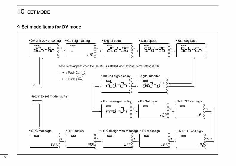
These items appear when the UT-118 is installed, and Optional items setting is ON.
• Digital monitor
Return to set mode ((p. 49))
• Call sign setting• DV unit power setting • Digital code • Data speed • Standby beep
• Rx Call sign display
• Rx message display • Rx Call sign
• GPS message • Rx Position • Rx Call sign with message • Rx message
• Rx RPT1 call sign
• Rx RPT2 call sign
: Push
: Push
SETSKIP
ATTPRIO
D Set mode items for DV mode
52
10SET MODE
10
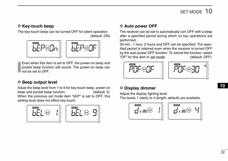
D Key-touch beepThe key-touch beep can be turned OFF for silent operation.
(default: ON)
Even when this item is set to OFF, the power-on beep andpocket beep function still sound. The power-on beep cannot be set to OFF.
D Beep output levelAdust the beep level from 1 to 9 for key-touch beep, power-onbeep and pocket beep function. (default: 5)When the previous set mode item “bEP” is set to OFF, thissetting level does not affect key-touch.
D Auto power OFFThe receiver can be set to automatically turn OFF with a beepafter a specified period during which no key operations areperformed.30 min., 1 hour, 2 hours and OFF can be specified. The spec-ified period is retained even when the receiver is turned OFFby the auto power OFF function. To cancel the function, select“OF” for this item in set mode. (default: OFF)
D Display dimmerAdjust the display lighting level.The levels 1 (dark) to 4 (bright: default) are available.
53
10 SET MODE
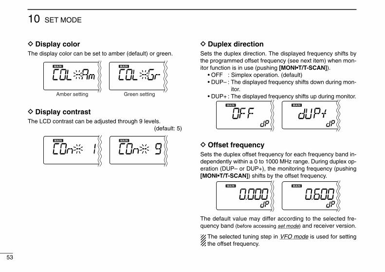
D Display colorThe display color can be set to amber (default) or green.
D Display contrastThe LCD contrast can be adjusted through 9 levels.
(default: 5)
D Duplex directionSets the duplex direction. The displayed frequency shifts bythe programmed offset frequency (see next item) when mon-itor function is in use (pushing [MONI•T/T-SCAN]).
• OFF : Simplex operation. (default)• DUP– : The displayed frequency shifts down during mon-
itor.• DUP+ : The displayed frequency shifts up during monitor.
D Offset frequencySets the duplex offset frequency for each frequency band in-dependently within a 0 to 1000 MHz range. During duplex op-eration (DUP– or DUP+), the monitoring frequency (pushing[MONI•T/T-SCAN]) shifts by the offset frequency.
The default value may differ according to the selected fre-quency band (before accessing set mode) and receiver version.
The selected tuning step in VFO mode is used for settingthe offset frequency.
Green settingAmber setting
54
10SET MODE
12345678910111213141516
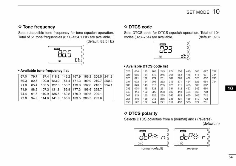
D Tone frequencySets subaudible tone frequency for tone squelch operation.Total of 51 tone frequencies (67.0–254.1 Hz) are available.
(default: 88.5 Hz)
• Available tone frequency list
D DTCS codeSets DTCS code for DTCS squelch operation. Total of 104codes (023–754) are available. (default: 023)
• Available DTCS code list
D DTCS polaritySelects DTCS polarities from n (normal) and r (reverse).
(default: n)
normal (default) reverse
023025026031032036043047051053
125131132134143145152155156162
245246251252255261263265266271
356364365371411412413423431432
506516523526532546565606612624
054065071072073074114115116122
165172174205212223225226243244
274306311315325331332343346351
445446452454455462464465466503
627631632654662664703712723731
732734743754
67.069.371.071.974.477.0
79.782.585.488.591.594.8
097.4100.0103.5107.2110.9114.8
118.8123.0127.3131.8136.5141.3
146.2151.4156.7159.8162.2165.5
167.9171.3173.8177.3179.9183.5
186.2189.9192.8196.6199.5203.5
206.5210.7218.1225.7229.1233.6
241.8250.3254.1
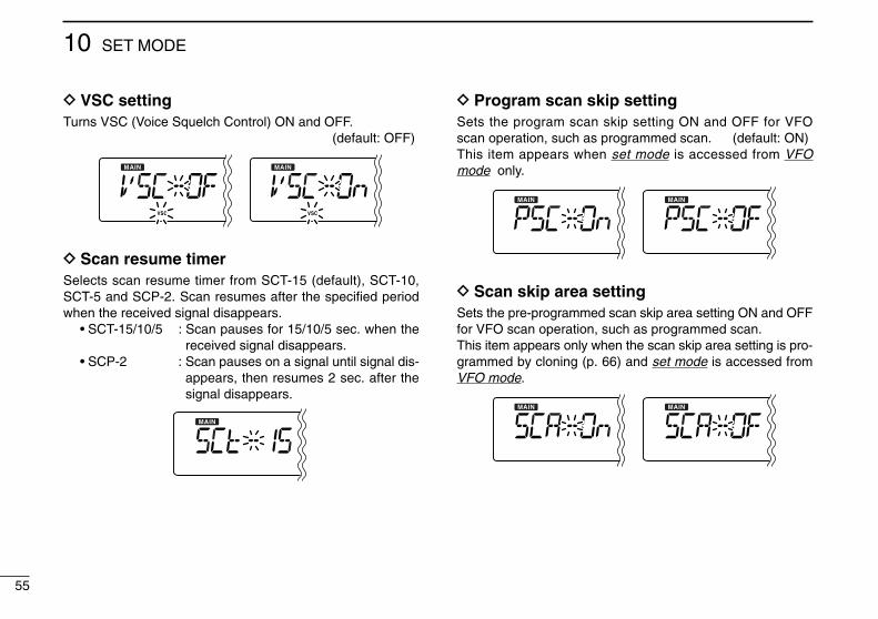
55
10 SET MODE
D VSC settingTurns VSC (Voice Squelch Control) ON and OFF.
(default: OFF)
D Scan resume timerSelects scan resume timer from SCT-15 (default), SCT-10,SCT-5 and SCP-2. Scan resumes after the specified periodwhen the received signal disappears.
• SCT-15/10/5 : Scan pauses for 15/10/5 sec. when thereceived signal disappears.
• SCP-2 : Scan pauses on a signal until signal dis-appears, then resumes 2 sec. after thesignal disappears.
D Program scan skip settingSets the program scan skip setting ON and OFF for VFOscan operation, such as programmed scan. (default: ON)This item appears when set mode is accessed from VFOmode only.
D Scan skip area settingSets the pre-programmed scan skip area setting ON and OFFfor VFO scan operation, such as programmed scan.This item appears only when the scan skip area setting is pro-grammed by cloning (p. 66) and set mode is accessed fromVFO mode.
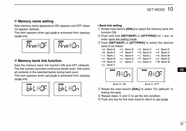
56
10SET MODE
12345678910111213141516
D Memory name settingSets memory name appearance ON (appear) and OFF (doesnot appear; default).This item appears when set mode is accessed from memorymode only.
D Memory bank link functionSets the memory bank link function ON and OFF (default).The link function provides continuous banks scan, that scansall contents in the selected banks during bank scan.This item appears when set mode is accessed from memorymode only.
• Bank link settingq Rotate main band’s [DIAL] to select the memory bank link
function ON.w Push and hold [SET•SKIP] or [ATT•PRIO] for 1 sec. to
enter bank link setting mode.e Push [SET•SKIP] or [ATT•PRIO] to select the desired
bank to be linked.• A : Bank A • b : Bank B • C : Bank C • d : Bank D• E : Bank E • F : Bank F • G : Bank G • H : Bank H• J : Bank J • k : Bank K • L : Bank L • m : Bank M• n : Bank N • o : Bank O • P : Bank P • q : Bank Q• R : Bank R • t : Bank T • U : Bank U • W: Bank W• y : Bank Y
r Rotate the main band’s [DIAL] to select “On (default)” tolinking the bank.
t Repeat steps e and r to set the link condition.y Push any key for the main band to return to set mode.
Bank A: ON Bank A: OFF
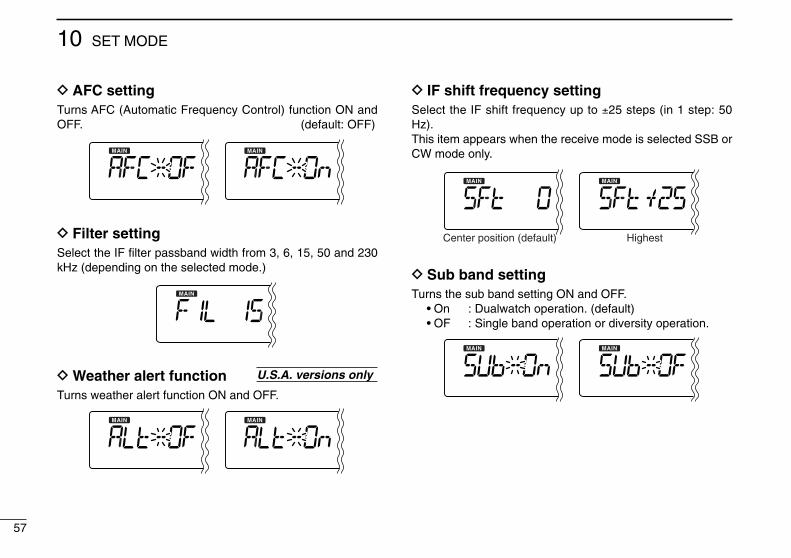
57
10 SET MODE
D AFC settingTurns AFC (Automatic Frequency Control) function ON andOFF. (default: OFF)
D Filter settingSelect the IF filter passband width from 3, 6, 15, 50 and 230kHz (depending on the selected mode.)
D Weather alert functionTurns weather alert function ON and OFF.
D IF shift frequency settingSelect the IF shift frequency up to ±25 steps (in 1 step: 50Hz).This item appears when the receive mode is selected SSB orCW mode only.
D Sub band settingTurns the sub band setting ON and OFF.
• On : Dualwatch operation. (default)• OF : Single band operation or diversity operation.
Center position (default) Highest
U.S.A. versions only
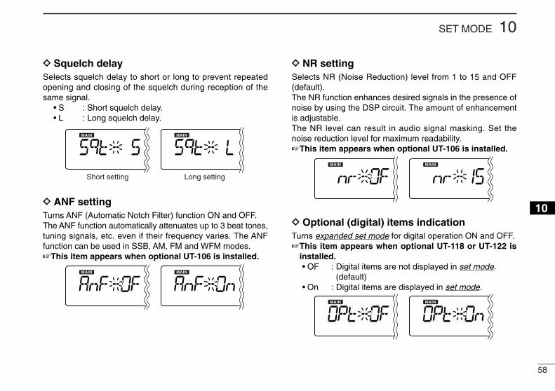
58
10SET MODE
12345678910111213141516
D Squelch delaySelects squelch delay to short or long to prevent repeatedopening and closing of the squelch during reception of thesame signal.
• S : Short squelch delay.• L : Long squelch delay.
D ANF settingTurns ANF (Automatic Notch Filter) function ON and OFF.The ANF function automatically attenuates up to 3 beat tones,tuning signals, etc. even if their frequency varies. The ANFfunction can be used in SSB, AM, FM and WFM modes.☞This item appears when optional UT-106 is installed.
D NR settingSelects NR (Noise Reduction) level from 1 to 15 and OFF(default).The NR function enhances desired signals in the presence ofnoise by using the DSP circuit. The amount of enhancementis adjustable.The NR level can result in audio signal masking. Set thenoise reduction level for maximum readability.☞This item appears when optional UT-106 is installed.
D Optional (digital) items indicationTurns expanded set mode for digital operation ON and OFF.☞This item appears when optional UT-118 or UT-122 is
installed.• OF : Digital items are not displayed in set mode.
(default)• On : Digital items are displayed in set mode.
Short setting Long setting
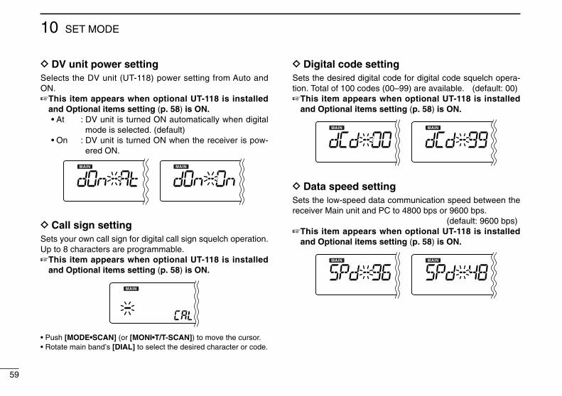
59
10 SET MODE
D DV unit power settingSelects the DV unit (UT-118) power setting from Auto andON.☞This item appears when optional UT-118 is installed
and Optional items setting (p. 58) is ON.• At : DV unit is turned ON automatically when digital
mode is selected. (default)• On : DV unit is turned ON when the receiver is pow-
ered ON.
D Call sign settingSets your own call sign for digital call sign squelch operation.Up to 8 characters are programmable.☞This item appears when optional UT-118 is installed
and Optional items setting (p. 58) is ON.
• Push [MODE•SCAN] (or [MONI•T/T-SCAN]) to move the cursor.• Rotate main band’s [DIAL] to select the desired character or code.
D Digital code settingSets the desired digital code for digital code squelch opera-tion. Total of 100 codes (00–99) are available. (default: 00)☞This item appears when optional UT-118 is installed
and Optional items setting (p. 58) is ON.
D Data speed settingSets the low-speed data communication speed between thereceiver Main unit and PC to 4800 bps or 9600 bps.
(default: 9600 bps)☞This item appears when optional UT-118 is installed
and Optional items setting (p. 58) is ON.
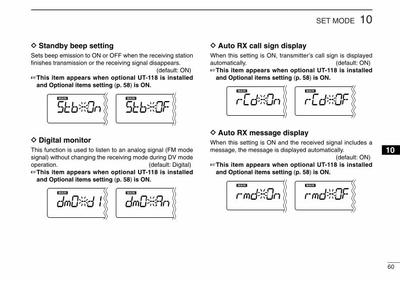
60
10SET MODE
12345678910111213141516
D Standby beep settingSets beep emission to ON or OFF when the receiving stationfinishes transmission or the receiving signal disappears.
(default: ON)☞This item appears when optional UT-118 is installed
and Optional items setting (p. 58) is ON.
D Digital monitorThis function is used to listen to an analog signal (FM modesignal) without changing the receiving mode during DV modeoperation. (default: Digital)☞This item appears when optional UT-118 is installed
and Optional items setting (p. 58) is ON.
D Auto RX call sign displayWhen this setting is ON, transmitter’s call sign is displayedautomatically. (default: ON)☞This item appears when optional UT-118 is installed
and Optional items setting (p. 58) is ON.
D Auto RX message displayWhen this setting is ON and the received signal includes amessage, the message is displayed automatically.
(default: ON)☞This item appears when optional UT-118 is installed
and Optional items setting (p. 58) is ON.
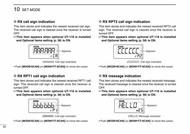
61
10 SET MODE
D RX call sign indicationThis item stores and indicates the newest received call sign.The received call sign is cleared once the receiver is turnedOFF.☞This item appears when optional UT-118 is installed
and Optional items setting (p. 58) is ON.
• Push [MODE•SCAN] (or [MONI•T/T-SCAN]) to move the cursor.
D RX RPT1 call sign indicationThis item stores and indicates the newest received RPT1 callsign. The received call sign is cleared once the receiver isturned OFF.☞This item appears when optional UT-118 is installed
and Optional items setting (p. 58) is ON.
• Push [MODE•SCAN] (or [MONI•T/T-SCAN]) to move the cursor.
D RX RPT2 call sign indicationThis item stores and indicates the newest received RPT2 callsign. The received call sign is cleared once the receiver isturned OFF.☞This item appears when optional UT-118 is installed
and Optional items setting (p. 58) is ON.
• Push [MODE•SCAN] (or [MONI•T/T-SCAN]) to move the cursor.
D RX message indicationThis item stores and indicates the newest received message.The received message is cleared once the receiver is turnedOFF.☞This item appears when optional UT-118 is installed
and Optional items setting (p. 58) is ON.
• Push [MODE•SCAN] (or [MONI•T/T-SCAN]) to move the cursor.
Appears
(HELLO: Message example)
Appears
(CCCCCC: Call sign example)
(BBBBBB: Call sign example)
Appears
Appears
(AAAAAA: Call sign example)
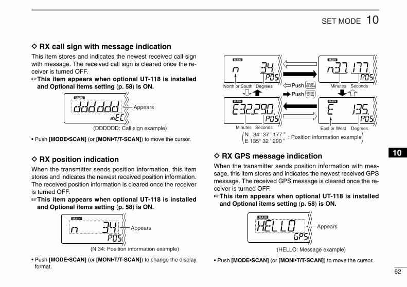
62
10SET MODE
12345678910111213141516
D RX call sign with message indicationThis item stores and indicates the newest received call signwith message. The received call sign is cleared once the re-ceiver is turned OFF.☞This item appears when optional UT-118 is installed
and Optional items setting (p. 58) is ON.
• Push [MODE•SCAN] (or [MONI•T/T-SCAN]) to move the cursor.
D RX position indicationWhen the transmitter sends position information, this itemstores and indicates the newest received position information.The received position information is cleared once the receiveris turned OFF.☞This item appears when optional UT-118 is installed
and Optional items setting (p. 58) is ON.
• Push [MODE•SCAN] (or [MONI•T/T-SCAN]) to change the displayformat.
D RX GPS message indicationWhen the transmitter sends position information with mes-sage, this item stores and indicates the newest received GPSmessage. The received GPS message is cleared once the re-ceiver is turned OFF.☞This item appears when optional UT-118 is installed
and Optional items setting (p. 58) is ON.
• Push [MODE•SCAN] (or [MONI•T/T-SCAN]) to move the cursor.
Appears
(HELLO: Message example)
Push
Push
DegreesNorth or South Minutes Seconds
DegreesEast or WestMinutes Seconds
N 34° 37 ’ 177 ” E 135° 32 ’ 290 ”
: Position information example
MONIT/T-SCAN
MODESCAN
Appears
(N 34: Position information example)
(DDDDDD: Call sign example)
Appears
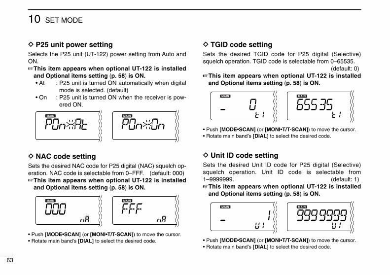
63
10 SET MODE
D P25 unit power settingSelects the P25 unit (UT-122) power setting from Auto andON.☞This item appears when optional UT-122 is installed
and Optional items setting (p. 58) is ON.• At : P25 unit is turned ON automatically when digital
mode is selected. (default)• On : P25 unit is turned ON when the receiver is pow-
ered ON.
D NAC code settingSets the desired NAC code for P25 digital (NAC) squelch op-eration. NAC code is selectable from 0–FFF. (default: 000)☞This item appears when optional UT-122 is installed
and Optional items setting (p. 58) is ON.
• Push [MODE•SCAN] (or [MONI•T/T-SCAN]) to move the cursor.• Rotate main band’s [DIAL] to select the desired code.
D TGID code settingSets the desired TGID code for P25 digital (Selective)squelch operation. TGID code is selectable from 0–65535.
(default: 0)☞This item appears when optional UT-122 is installed
and Optional items setting (p. 58) is ON.
• Push [MODE•SCAN] (or [MONI•T/T-SCAN]) to move the cursor.• Rotate main band’s [DIAL] to select the desired code.
D Unit ID code settingSets the desired Unit ID code for P25 digital (Selective)squelch operation. Unit ID code is selectable from1–9999999. (default: 1)☞This item appears when optional UT-122 is installed
and Optional items setting (p. 58) is ON.
• Push [MODE•SCAN] (or [MONI•T/T-SCAN]) to move the cursor.• Rotate main band’s [DIAL] to select the desired code.
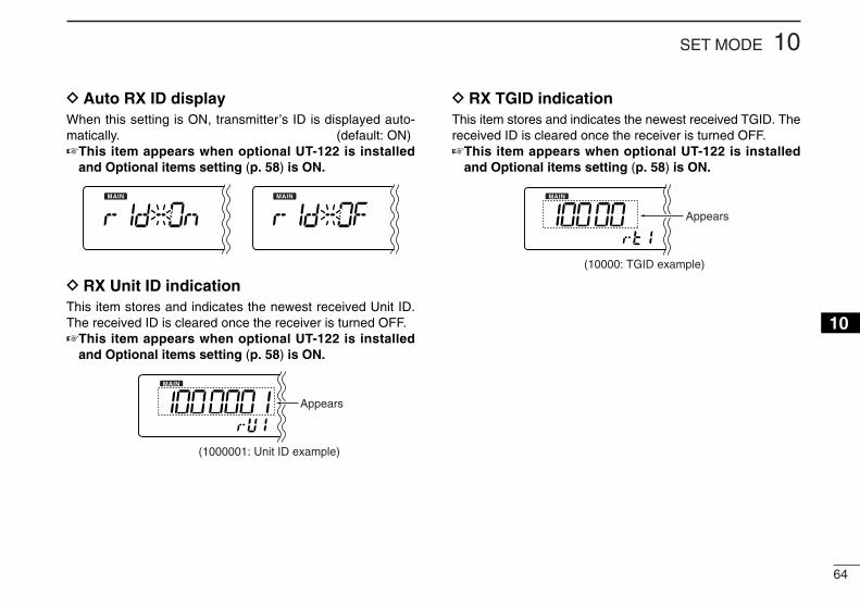
64
10SET MODE
12345678910111213141516
D Auto RX ID displayWhen this setting is ON, transmitter’s ID is displayed auto-matically. (default: ON)☞This item appears when optional UT-122 is installed
and Optional items setting (p. 58) is ON.
D RX Unit ID indicationThis item stores and indicates the newest received Unit ID.The received ID is cleared once the receiver is turned OFF.☞This item appears when optional UT-122 is installed
and Optional items setting (p. 58) is ON.
D RX TGID indicationThis item stores and indicates the newest received TGID. Thereceived ID is cleared once the receiver is turned OFF.☞This item appears when optional UT-122 is installed
and Optional items setting (p. 58) is ON.
(10000: TGID example)
Appears
(1000001: Unit ID example)
Appears
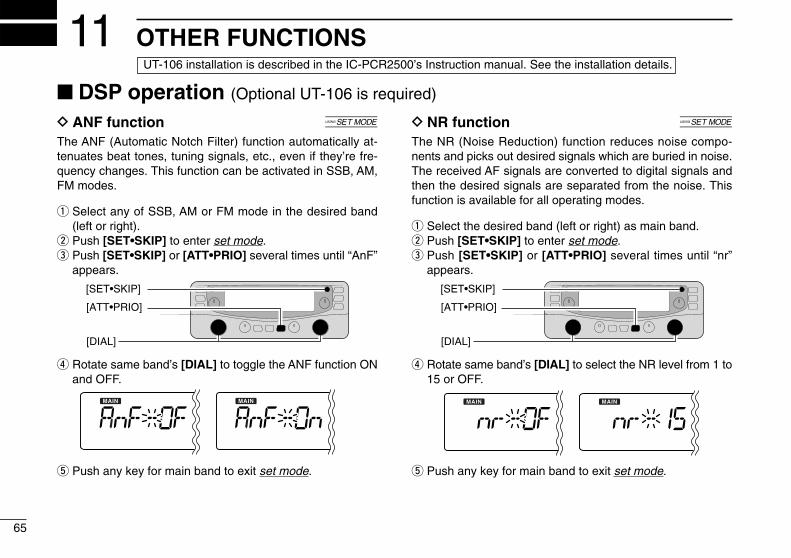
65
OTHER FUNCTIONS11
D ANF function [
The ANF (Automatic Notch Filter) function automatically at-tenuates beat tones, tuning signals, etc., even if they’re fre-quency changes. This function can be activated in SSB, AM,FM modes.
q Select any of SSB, AM or FM mode in the desired band(left or right).
w Push [SET•SKIP] to enter set mode.e Push [SET•SKIP] or [ATT•PRIO] several times until “AnF”
appears.
r Rotate same band’s [DIAL] to toggle the ANF function ONand OFF.
t Push any key for main band to exit set mode.
D NR function [
The NR (Noise Reduction) function reduces noise compo-nents and picks out desired signals which are buried in noise.The received AF signals are converted to digital signals andthen the desired signals are separated from the noise. Thisfunction is available for all operating modes.
q Select the desired band (left or right) as main band.w Push [SET•SKIP] to enter set mode.e Push [SET•SKIP] or [ATT•PRIO] several times until “nr”
appears.
r Rotate same band’s [DIAL] to select the NR level from 1 to15 or OFF.
t Push any key for main band to exit set mode.
[SET•SKIP]
[DIAL]
[ATT•PRIO]
[SET•SKIP]
[DIAL]
[ATT•PRIO]
■ DSP operation (Optional UT-106 is required)
UT-106 installation is described in the IC-PCR2500’s Instruction manual. See the installation details.
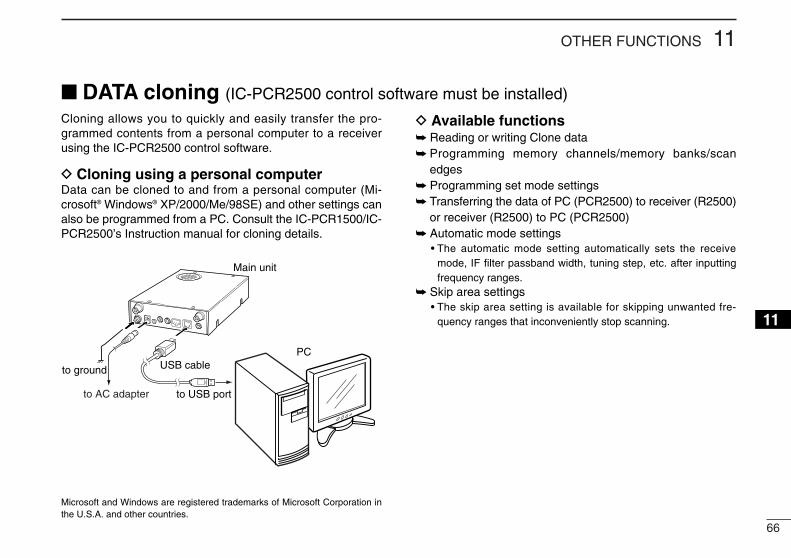
66
11OTHER FUNCTIONS
12345678910111213141516
Cloning allows you to quickly and easily transfer the pro-grammed contents from a personal computer to a receiverusing the IC-PCR2500 control software.
D Cloning using a personal computerData can be cloned to and from a personal computer (Mi-crosoft® Windows® XP/2000/Me/98SE) and other settings canalso be programmed from a PC. Consult the IC-PCR1500/IC-PCR2500’s Instruction manual for cloning details.
D Available functions➥ Reading or writing Clone data➥ Programming memory channels/memory banks/scan
edges➥ Programming set mode settings➥ Transferring the data of PC (PCR2500) to receiver (R2500)
or receiver (R2500) to PC (PCR2500)➥ Automatic mode settings
• The automatic mode setting automatically sets the receivemode, IF filter passband width, tuning step, etc. after inputtingfrequency ranges.
➥ Skip area settings• The skip area setting is available for skipping unwanted fre-
quency ranges that inconveniently stop scanning.
Main unit
to ground
PC
to USB port
USB cable
to AC adapter
■ DATA cloning (IC-PCR2500 control software must be installed)
Microsoft and Windows are registered trademarks of Microsoft Corporation inthe U.S.A. and other countries.
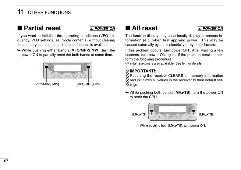
67
11 OTHER FUNCTIONS
■ Partial resetIf you want to initialize the operating conditions (VFO fre-quency, VFO settings, set mode contents) without clearingthe memory contents, a partial reset function is available.
➥ While pushing either band’s [VFO/MR•S.MW], turn thepower ON to partially reset the both bands at same time.
■ All resetThe function display may occasionally display erroneous in-formation (e.g. when first applying power). This may becaused externally by static electricity or by other factors.
If this problem occurs, turn power OFF. After waiting a fewseconds, turn power ON again. If the problem persists, per-form the following procedure.• Partial resetting is also available. See left for details.
IMPORTANT!:Resetting the receiver CLEARS all memory informationand initializes all values in the receiver to their default set-tings.
➥ While pushing both band’s [MHz•TS], turn the power ONto reset the CPU.
[MHz•TS]
While pushing both [MHz•TS], turn power ON.
[MHz•TS]
AT POWER ON
[VFO/MR•S.MW] [VFO/MR•S.MW]
AT POWER ON
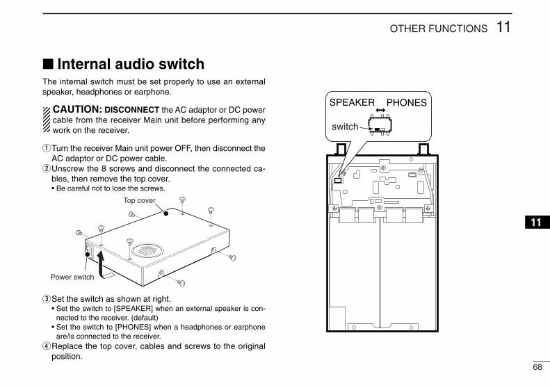
68
11OTHER FUNCTIONS
12345678910111213141516
■ Internal audio switchThe internal switch must be set properly to use an externalspeaker, headphones or earphone.
CAUTION: DISCONNECT the AC adaptor or DC powercable from the receiver Main unit before performing anywork on the receiver.
qTurn the receiver Main unit power OFF, then disconnect theAC adaptor or DC power cable.
wUnscrew the 8 screws and disconnect the connected ca-bles, then remove the top cover.• Be careful not to lose the screws.
eSet the switch as shown at right.• Set the switch to [SPEAKER] when an external speaker is con-
nected to the receiver. (default)• Set the switch to [PHONES] when a headphones or earphone
are/is connected to the receiver.rReplace the top cover, cables and screws to the original
position.
SPEAKER PHONES
switch
Top cover
Power switch
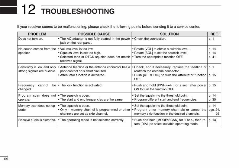
69
TROUBLESHOOTING12
PROBLEM POSSIBLE CAUSE SOLUTION REF.
If your receiver seems to be malfunctioning, please check the following points before sending it to a service center.
Does not turn on.
No sound comes from thespeaker.
Sensitivity is low and onlystrong signals are audible.
Frequency cannot bechanged.
Program scan does notoperate.
Memory scan does not op-erate.
Receive audio is distorted.
• The AC adapter is not fully seated in the powerjack on the rear panel.
• Volume level is too low.• Squelch level is set too high.• Selected tone or DTCS squelch does not match
received signal.
• Antenna feedline or the antenna connector has apoor contact or is short circuited.
• Attenuator function is activated.
• The lock function is activated.
• The squelch is open.• The start and end frequencies are the same.
• The squelch is open.• Only 1 memory channel is programmed or other
channels are set as skip channel.
• The operating mode is not selected correctly.
• Check the connection.
• Rotate [VOL] to obtain a suitable level.• Rotate [SQL] to set the squelch level.• Turn the appropriate function OFF.
• Check, and if necessary, replace the feedline orreattach the antenna connector..
• Push [ATT•PRIO] to turn the Attenuator functionOFF.
• Push and hold [PWR• ] for 2 sec. after powerON to turn the function OFF.
• Set the squelch to the threshold point.• Program different start and end frequencies.
• Set the squelch to the threshold point.• Program other memory channels or cancel the
memory skip function in the desired channels.
• Push and hold [MODE•SCAN] for 1 sec., then ro-tate [DIAL] to select suitable operating mode.
p. 1
p. 14p. 14p. 41
p. 1
p. 15
p. 15
p. 14p. 35
p. 14pgs. 24,
36
p. 13
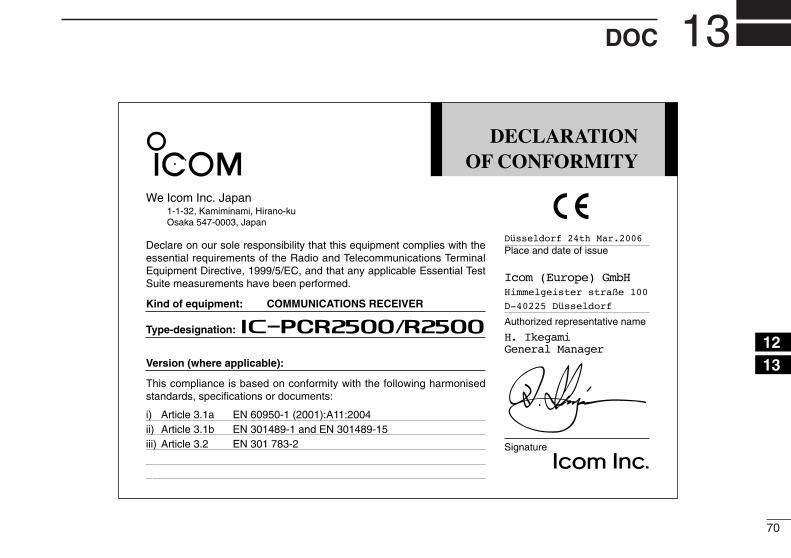
70
13DOC
12345678910111213141516
DECLARATIONOF CONFORMITY
We Icom Inc. Japan1-1-32, Kamiminami, Hirano-kuOsaka 547-0003, Japan
Declare on our sole responsibility that this equipment complies with theessential requirements of the Radio and Telecommunications TerminalEquipment Directive, 1999/5/EC, and that any applicable Essential TestSuite measurements have been performed.
Kind of equipment: COMMUNICATIONS RECEIVER
Type-designation: iPCR2500/R2500
Version (where applicable):
This compliance is based on conformity with the following harmonisedstandards, specifications or documents:
i) Article 3.1a EN 60950-1 (2001):A11:2004ii) Article 3.1b EN 301489-1 and EN 301489-15iii) Article 3.2 EN 301 783-2iv)v)
Düsseldorf 24th Mar.2006Place and date of issue
Icom (Europe) GmbHHimmelgeister straße 100
D-40225 Düsseldorf
Authorized representative name
H. IkegamiGeneral Manager
Signature
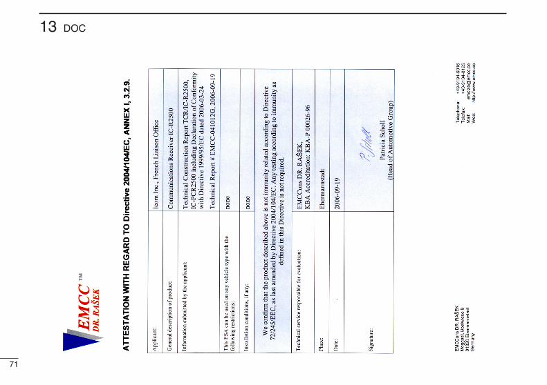
71
13 DOC

72
12345678910111213141516
MEMO
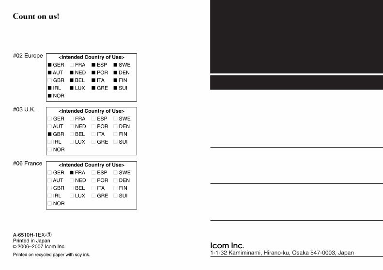
1-1-32 Kamiminami, Hirano-ku, Osaka 547-0003, Japan
<Intended Country of Use>
■ GER ■ FRA ■ ESP ■ SWE
■ AUT ■ NED ■ POR ■ DEN
■ GBR ■ BEL ■ ITA ■ FIN
■ IRL ■ LUX ■ GRE ■ SUI
■ NOR
<Intended Country of Use>
■ GER ■ FRA ■ ESP ■ SWE
■ AUT ■ NED ■ POR ■ DEN
■ GBR ■ BEL ■ ITA ■ FIN
■ IRL ■ LUX ■ GRE ■ SUI
■ NOR
#02 Europe
#03 U.K.
<Intended Country of Use>
■ GER ■ FRA ■ ESP ■ SWE
■ AUT ■ NED ■ POR ■ DEN
■ GBR ■ BEL ■ ITA ■ FIN
■ IRL ■ LUX ■ GRE ■ SUI
■ NOR
#06 France
A-6510H-1EX-ePrinted in Japan© 2006–2007 Icom Inc.
Printed on recycled paper with soy ink.


![COMMUNICATIONS RECEIVER iC-r8500 - アイコム …1 MEMORY SET SWITCH [M-SET] (p. 19) Used to ‘copy and paste’ the displayed frequency into another memory channel. • The first](https://img.pdfslide.net/doc/110x75/5b1de4c07f8b9ac96a8b8410/communications-receiver-ic-r8500-1-memory-set-switch-m-set-p.jpg)