Embed Size (px)
Citation preview
1
THE BRIGHT STAR IN UTILITY COMMUNICATIONS
1
A leading global manufacturer of
electronic instruments and electromechanical devices
1Clear Vision • Sound Strategies • Solid Performance
Communication System
For
Smart Grid Ready
Electrical Substation
Presented to
(NYISO)
(12/9/10)
Presented by: K Naik

2
THE BRIGHT STAR IN UTILITY COMMUNICATIONS
Smart Grid Working Definition
An Electric Utility transmission and distribution
infrastructure which securely incorporates information and
communications technology into all aspects of energy
supply, delivery and consumption to enable energy markets,
improve system reliability and customer service, reduce
operational and customer costs, improve efficiency and
minimize environmental impacts.
Integrys definition – UTC Smart Grid Workshop 2009

3
THE BRIGHT STAR IN UTILITY COMMUNICATIONS
Smart Grid General Definition
• “Intelligent” Utility Network enabled by End-to-End,
Overlapping Networks tied to “Smart” devices and sensors
• Smart Devices include –– Smart Meters
– Smart Home Appliances
– Remoter Terminal Units
– Video Cameras
– Sensors
• Capturing customer key data and information
• Capturing network data and information

4
THE BRIGHT STAR IN UTILITY COMMUNICATIONS
A Coordinated Substation system is a must
A Coordinated system should cover:
• Standards
• Planning
• Products
• Various Dept.
• System Engineering
• System Communication
• Personnel

5
THE BRIGHT STAR IN UTILITY COMMUNICATIONS
Why, a Coordinated system is required?
• To meet government standards/Norms • NERC,
• CIP,
• etc.
• To meet industry standards • IEEE 1613
• 61850
• etc.
• Deliver better reliable cost effective product to the consumer
• Protect the assets• Provide system access to preapproved staff only
• Protect the data

6
THE BRIGHT STAR IN UTILITY COMMUNICATIONS
What is involved in the Coordination?
• Intelligent IEDs (PMU, RTU, Relays, Comms, etc.)
• Substation grade Reliable products (High performance in all
conditions)
• Security (Meet the industry and Government standards)
• Coordinated system solution (Meet internal and industry
norms)
• etc.

7
THE BRIGHT STAR IN UTILITY COMMUNICATIONS
Who needs a Coordinated system Solution
• Generation,Transmission and Distribution E. Utilities– Substation Engineers,
– Relay Engineers
– Telecom Engineers
– Planning Engineers
– IT Engineers

8
THE BRIGHT STAR IN UTILITY COMMUNICATIONS
What Devices are involved in Substation?
• Protection Relays for various schemes (Current diff.
Directional Comp., Direct transfer trips etc.)
• RTU and Scada Devices
• Fault Recorders (PMUs)
• Admin data transport devices (routers, switches, etc.)
• Voice communication Units (PABX, cross connects)
• Video Surveillance units
• Substation LANs devices
• Communication devices internal and external (PLCs,
Multiplexers, Tone equipment etc.)

9
THE BRIGHT STAR IN UTILITY COMMUNICATIONS
Communication system planning concerns
• Look for industry standards compliant flexible products
• Ability to integrate old & new technologies (transport capacity)
• Allow access to old and new field devices (IEDS)
• Secure access to complete system on demand

10
THE BRIGHT STAR IN UTILITY COMMUNICATIONS
Telecom System Overview
RTU
PMU
RELAY
Data
Telecom
Teleprotection
Etc.
T1
E1
DS1
Channel Bank
Sonet
Ethernet Switches
SDH
IED
Access Mux.
Transport Device
Fiber Optic Cable
Digital Microwave
Leased Lines
Media

11
THE BRIGHT STAR IN UTILITY COMMUNICATIONS
Integrated Communication System Example
Dedicated
LAN
Internet
Remote admin
Layer 3 Router - MPLS
enabled tunnel, or through
SONET (EOS or DS1 TDM)
T1/E1
Loop
FOCUST1/E1 Tie
Local
CO
FOCUS or Brand X Spur
BB FOCUS
BB FOCUSBB FOCUS
FOCUS or Brand X Spur
T1/E1
T1/E1

13
THE BRIGHT STAR IN UTILITY COMMUNICATIONS
Ethernet Standards
Institute of Electrical Engineers – IEEE~ Leading authority on technology for 125 years, dedicated to Ethernet practices
focusing on open standards for everyone to use and follow
Metro Ethernet Forum – MEF~ MEF is a global industry alliance comprising more than 145 organizations
including telecommunications service providers, cable operators, MSOs, network
equipment, test vendors, labs and software manufacturers, semiconductors
vendors and testing organizations. The MEF develops technical specifications and
implementation agreements to promote interoperability and deployment of
Carrier Ethernet worldwide.
Ethernet is an open standard which allows creative solutions to be developed
to solve a number of communications issues. Two main bodies support the
development of Ethernet and its advances

14
THE BRIGHT STAR IN UTILITY COMMUNICATIONS
Flexibility over full the application range
(DS0 to Packet)
• Can be a conventional DS0/T1/E1 TDM Multiplexer with up
to 8 T1/E1 ports, optical or electrical, or
• Can be a TDM to Packet Multiplexer, or– 100 Mbps optical or electrical line side interfaces
• Can be a TDM to Layer 2 Managed Ethernet Switch, or– 1000 Mbps optical SFP based line side interfaces
– Multiple 100 Mbps electrical client side interfaces
– With optional Substation Layer 2 Ethernet Switch integrated in BBF
• Both – Conventional TDM T1/E1 and Packet at the same
time

15
THE BRIGHT STAR IN UTILITY COMMUNICATIONS
Modular design, for ease of Use
• Integrated Modular TDM and Ethernet over Substation
Hardened Platform
• Transport Choices – T1 – over Private Fiber
– DS1 – over Microwave Radio and SONET infrastructures
– DS0/T1 Packetized over Ethernet infrastructure
– Any or All Transport Interfaces types can be used at the same time
• All Utility Applications from a single platform- Low and High Speed Data
-Gigabit Ethernet LAN/WAN
- 10/100 BaseT Fast Ethernet
-Protective Relaying
-SCADA
- Voice

16
THE BRIGHT STAR IN UTILITY COMMUNICATIONS
Modular design, for ease of use
• Hot Standby-Redundant Power Supply– Available as 48 Vdc, 125 Vdc/250 Vdc/120 Vac/240 Vac
• Transframer Module– Optical T1 1310nm and 1550nm – LC connectors
– Electrical DS1 – RJ48 , coaxial, or DB15 connectors
– Up to 4 ports (Up to 8 ports when using 2 Transframer Modules)
• Alternate Path Mode (APM) – High-Speed Path Switching
• SNMP Traps and V.3 Encryption

17
THE BRIGHT STAR IN UTILITY COMMUNICATIONS
Modular Construction
• Standard 19”, 4 RU Chassis
• 15 Universal Channel Module
Slots (position independent)
• Expansion Chassis (12 Additional
Module Slots)
• 6 System Module slots for – Power Supply Module ( 1 or 2)
– Transframer Module ( 4 T1 ports per
module, 1 or 2 modules)
– System Controller Module (1 or 2)
• Hot-swappable module design
• Expansion Chassis option

18
THE BRIGHT STAR IN UTILITY COMMUNICATIONS
Channel Modules
• Primary Voice and Data
Interface Modules– Two-Wire Voice (V2W, V2T)
– Four-Wire Voice (V4W)
– FXO
– FXS
– Addressable Two-Wire Voice
(PBW/PBT)
– Low Speed Data (RS-232)
– Party Line Data Module (PLD)
– High Speed Data (64V, 64R, 64G,
6NR/6NV
– Contact Transfer Module (CTR)
• Data Channel Unit (DCU)
• Protection and Mission
Critical Communications
Modules– Protective Relay Interface
• PRI
• PRS
– Pilot Wire Interface • HCB/HCB1
• SPD
– C37.94 Fiber Interface (6NF)
– Low Speed Data Interface (232)
• Sub-Rate Data Module – SRD-2
– SRD-4
– SRD-4N

19
THE BRIGHT STAR IN UTILITY COMMUNICATIONS
• QoS – prioritize critical traffic applications– Traffic marking and classification
• Optimized Bandwidth Utilization – control channel
bandwidth / channel latency
• VLAN ID – supports logical traffic separation
• Jitter Buffer size
• End to End Mapping – fast channel mapping without having
to set up pass through on in between nodes
Look for reliability, security & availability
Feature Rich - Integrated System – Mission Critical
20
THE BRIGHT STAR IN UTILITY COMMUNICATIONS
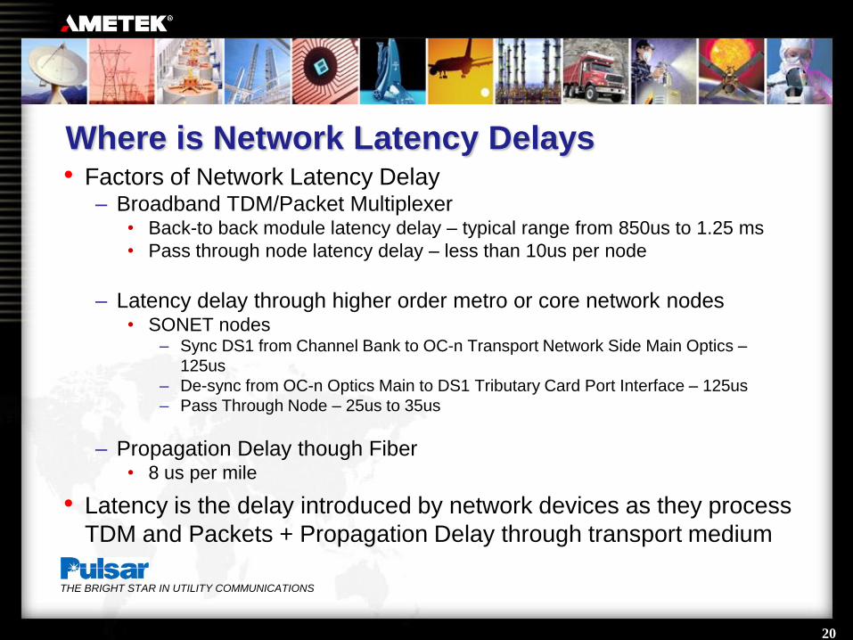
Where is Network Latency Delays• Factors of Network Latency Delay
– Broadband TDM/Packet Multiplexer• Back-to back module latency delay – typical range from 850us to 1.25 ms
• Pass through node latency delay – less than 10us per node
– Latency delay through higher order metro or core network nodes• SONET nodes
– Sync DS1 from Channel Bank to OC-n Transport Network Side Main Optics –
125us
– De-sync from OC-n Optics Main to DS1 Tributary Card Port Interface – 125us
– Pass Through Node – 25us to 35us
– Propagation Delay though Fiber • 8 us per mile
• Latency is the delay introduced by network devices as they process
TDM and Packets + Propagation Delay through transport medium
21
THE BRIGHT STAR IN UTILITY COMMUNICATIONS
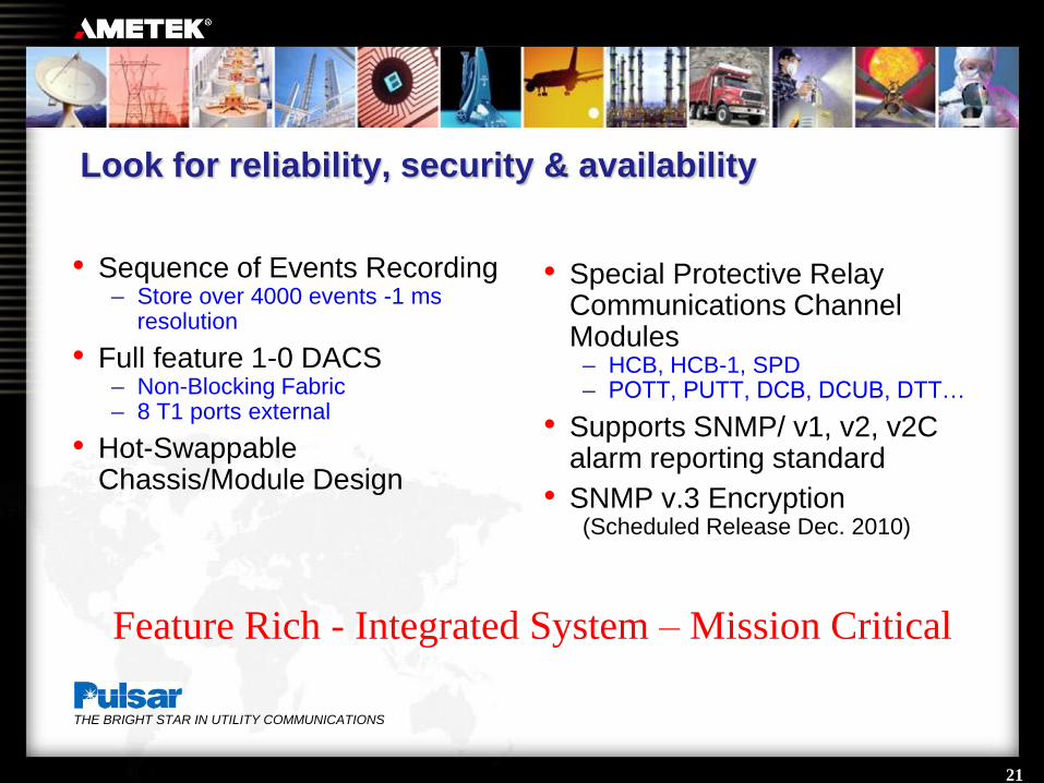
Look for reliability, security & availability
• Sequence of Events Recording – Store over 4000 events -1 ms
resolution
• Full feature 1-0 DACS– Non-Blocking Fabric– 8 T1 ports external
• Hot-Swappable Chassis/Module Design
• Special Protective Relay Communications Channel Modules
– HCB, HCB-1, SPD– POTT, PUTT, DCB, DCUB, DTT…
• Supports SNMP/ v1, v2, v2C alarm reporting standard
• SNMP v.3 Encryption(Scheduled Release Dec. 2010)
Feature Rich - Integrated System – Mission Critical

22
THE BRIGHT STAR IN UTILITY COMMUNICATIONS
DS0 Channels with 802.1q QoS Settings
• Prioritizes traffic flows by type of service
• Selectable QoS Bit from 0 through 7
• Can be set individually on each DS0 Channel Card
• Allows prioritizing of mission critical traffic through network
• Supported by MPLS enabled Switches and Routers
• Non-critical traffic (lower QoS Bit setting) will be interrupted
while mission critical traffic will continue to be transported
unaffected when network is over subscribed and congestion
occurs. This is critical for protective relaying
communications

23
THE BRIGHT STAR IN UTILITY COMMUNICATIONS
TDM to Ethernet…The Second Layer –
Layer 2/3 Ethernet/IP MPLS enabled Network
• MPLS Protocol Provides
Ethernet with functionality
like SONET and ATM
– Deterministic primary
path (service path)
– Deterministic alternate
path (protection path)
– Less than 50ms path
switching and restoration
• Supports QoS priority
service differentiation
• Provides traffic
engineering (TE) tools to
build LSP tunnels
• Is a Layer 2.5 protocol –
combines quick switching
and routing of interfaces

27
THE BRIGHT STAR IN UTILITY COMMUNICATIONS
Timing Sources – Internal and External
• Packet Clock– Internal Timing – Stratum 3 Clock
– External Timing• BITS Clock (GPS Stratum 1 source)
• DS1 (from upstream higher order transport network)
• Sequence of Events Time Tagging– 1 ms resolution for most events
• IRIG B (Both Modulated and Unmodulated)
• Network Timing Protocol (NTP)
28
THE BRIGHT STAR IN UTILITY COMMUNICATIONS
Operator friendly
• Web Browser based Element/Network Management System
• No proprietary NMS software required on PC
• Complete Node Set-up, Settings, Configurations,
Provisioning, Monitoring, and Management
• Events viewing and downloading
• Status viewing and downloading

29
THE BRIGHT STAR IN UTILITY COMMUNICATIONS
Operator friendly
• Channel mapping
• Administration functions such as setting up user accounts,
uploading firmware updates, password updates
• User Account Security– Administrator = IT Admin Functions and Password Changes
– User = Can make settings to any channel or mapping settings
– Super User = Combination of the Administrator and User Levels
– Guest User = Viewing only

30
THE BRIGHT STAR IN UTILITY COMMUNICATIONS
Look for user friendly flexible software

31
THE BRIGHT STAR IN UTILITY COMMUNICATIONS
Thank you!
“The Bright Star in Utility Communications”
Pulsar – AMETEK Power Instruments