Embed Size (px)
Citation preview
Communication SystemsyLecture 25
D I KiDong In KimSchool of Info/Comm Engineering
Sungkyunkwan University
1
Outline
Noise in Angle Modulation Phase deviation
Large SNR Small SNR
O SNR Output SNR PM FM FM
2
R i f A l d l iReview of Angle Modulation
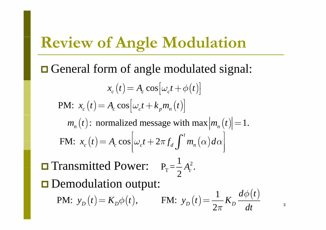
General form of angle modulated signal:( ) ( )cosx t A t tw fé ù= +ë û( ) ( )cosc c cx t A t tw fé ù= +ë û
( ) ( )PM: cosc c c p nx t A t k m twé ù= +ë û( ) ( ) : normalized message with max 1.n nm t m t =
( ) ( )FM: cos 2t
x t A t f m dw p a aé ù= +ê úò( ) ( )FM: cos 2c c c d nx t A t f m dw p a a= +ê úê úë ûò
Transmitted Power: 21P = ATransmitted Power: Demodulation output:
( )1 d tf
TP = .2 cA
3( ) ( ) ( )
( )1PM: , FM: 2D D D D
d ty t K t y t K
dtf
fp
= =
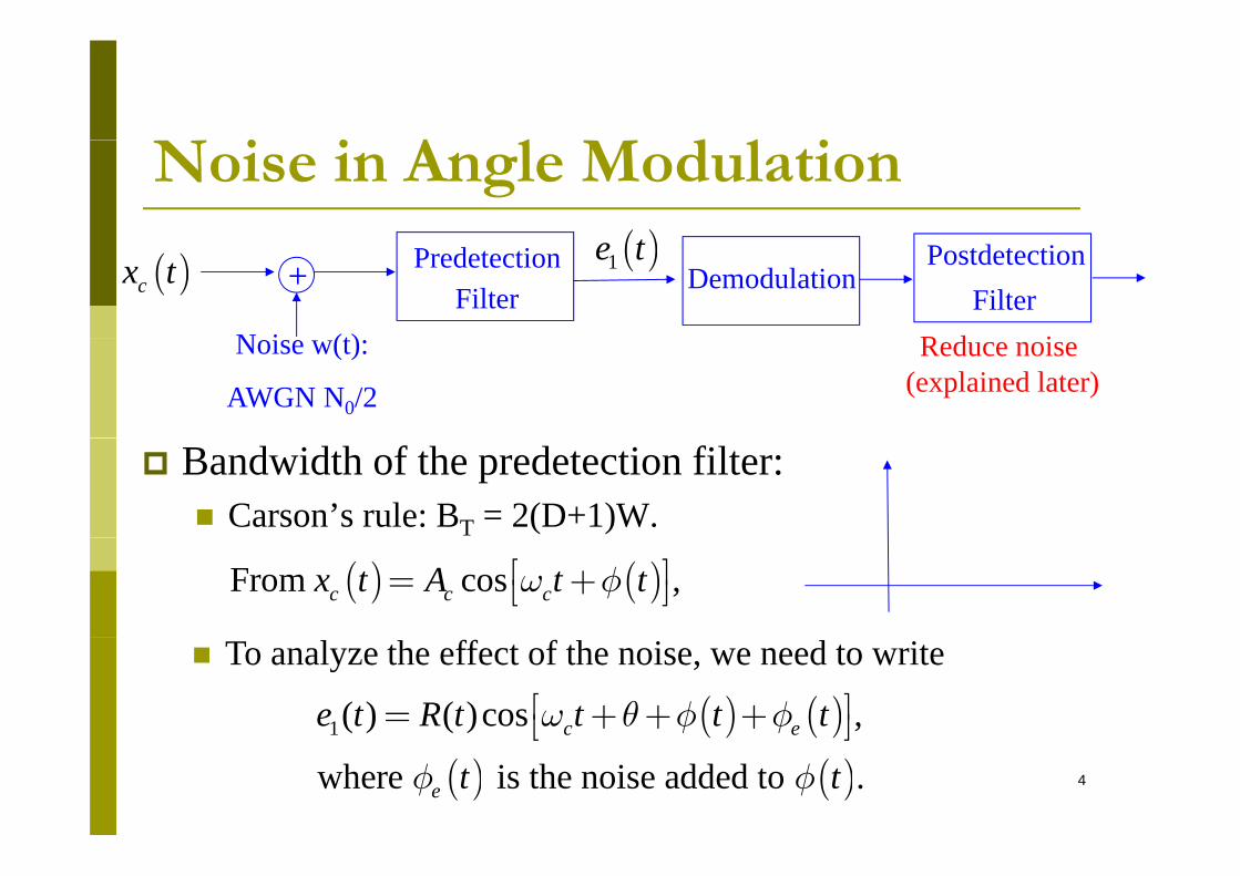
i i A l d l iNoise in Angle Modulation( )( )cx t +
N i (t)
PredetectionFilter
( )1e tDemodulation
FilterPostdetection
R d iNoise w(t):
AWGN N0/2
Reduce noise(explained later)
Bandwidth of the predetection filter: Carson’s rule: BT = 2(D+1)W.
( ) ( )From cos ,c c cx t A t tw fé ù= +ë û
To analyze the effect of the noise, we need to write
( ) ( )1( ) ( )cos ,c ee t R t t t tw q f fé ù= + + +ë û4
( ) ( )( ) ( )where is the noise added to .e t tf f
ë û
i i A l d l iNoise in Angle Modulation
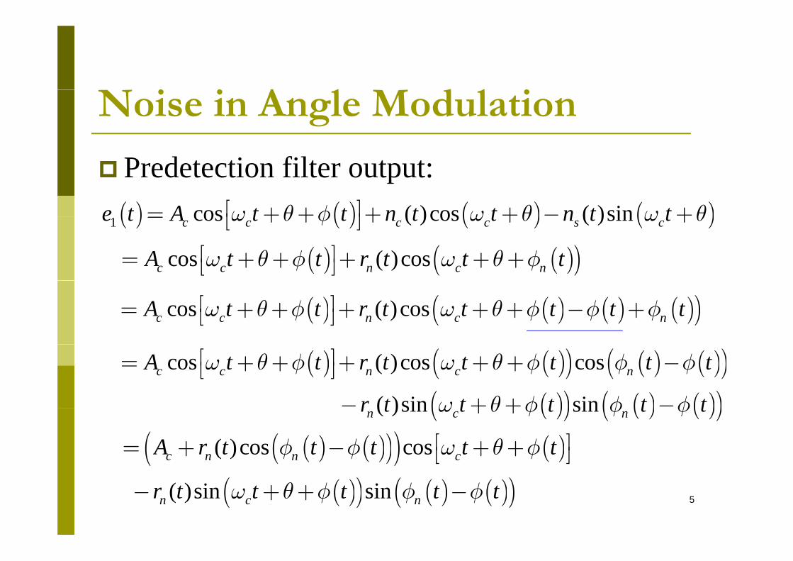
Predetection filter output:( ) ( ) ( ) ( )cos ( )cos ( )sine t A t t n t t n t tw q f w q w qé ù= + + + + - +ë û( ) ( ) ( ) ( )1 cos ( )cos ( )sinc c c c s ce t A t t n t t n t tw q f w q w q= + + + + +ë û
( ) ( )( )cos ( )cosc c n c nA t t r t t tw q f w q fé ù= + + + + +ë û
( ) ( ) ( ) ( )( )cos ( )cosc c n c nA t t r t t t t tw q f w q f f fé ù= + + + + + - +ë û
( ) ( )( ) ( ) ( )( )( )( ) ( ) ( )( )
cos ( )cos cos
( )sin sinc c n c nA t t r t t t t t
r t t t t t
w q f w q f f f
w q f f f
é ù= + + + + + -ë û- + + -( )( ) ( ) ( )( ) ( )sin sinn c nr t t t t tw q f f f+ +
( ) ( )( )( ) ( )( )cos cosc n n cA r t t t t tf f w q fé ù= + - + +ë û
5( )( ) ( ) ( )( ) ( )sin sinn c nr t t t t tw q f f f- + + -
i i A l d l iNoise in Angle Modulation( ) ( )( )( ) ( )é ù( ) ( )( )( ) ( )
( )( ) ( ) ( )( )1( ) ( )cos cos
( )sin sin
c n n c
n c n
e t A r t t t t t
r t t t t t
f f w q f
w q f f f
é ù= + - + +ë û
- + + -
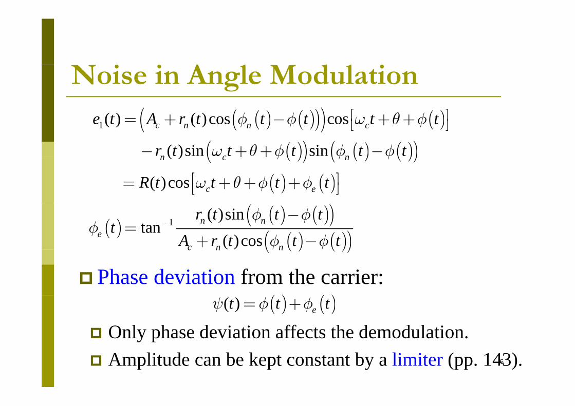
( ) ( )( )cos c eR t t t tw q f fé ù= + + +ë û
( )( ) ( ) ( )( )( )n c nf f f+ +
( )( ) ( )( )
( ) ( )( )1 ( )sin
tan( )cos
n ne
c n n
r t t tt
A r t t tf f
ff f
--
=+ -( ) ( )( )( )c n nf f
Phase deviation from the carrier:( ) ( )( ) ( )( ) et t ty f f= +
Only phase deviation affects the demodulation.6
y p Amplitude can be kept constant by a limiter (pp. 143).
Angle Modulation with High SNR
( )( ) ( )( ) ( ) ( )( )1 1( )sin ( )sin
t tn n n nr t t t r t t tt
f f f ff - -
- -
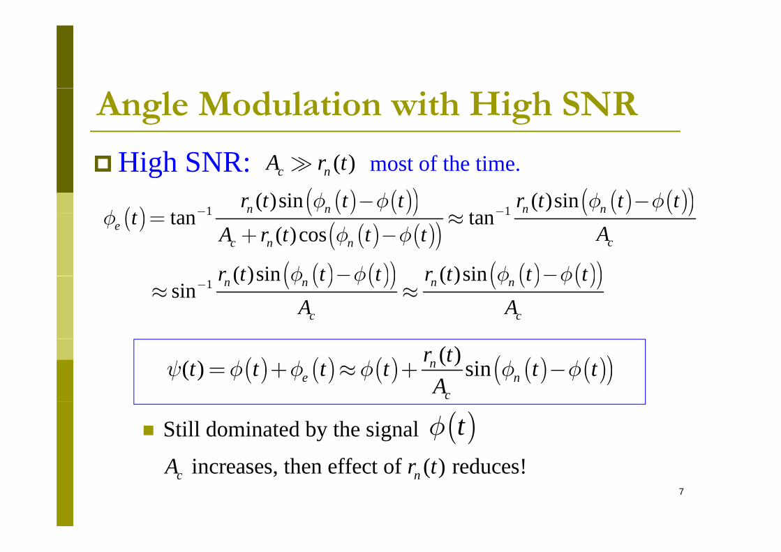
High SNR: ( )c nA r t most of the time.
( )( ) ( )( )
( ) ( )( )( ) ( )( )
( ) ( )( ) ( ) ( )( )
1 1tan tan( )cos
( )sin ( )sin
ecc n n
tAA r t t t
r t t t r t t t
ff f
f f f f
= »+ -
- -( ) ( )( ) ( ) ( )( )1 ( )sin ( )sin sin n n n n
c c
r t t t r t t tA Af f f f
-» »
( ) ( ) ( ) ( ) ( )( )( )( ) sinne n
c
r tt t t t t tA
y f f f f f= + » + -
increases then effect of ( ) reduces!A r t
Still dominated by the signal ( )tf
7
increases, then effect of ( ) reduces!c nA r t

A l d l i i h L S RAngle Modulation with Low SNRLow SNR: ( )A t t f th tiLow SNR: ( )c nA r t most of the time.
( ) : dominated by ( ).t ty f( ) : dominated by ( ).nt ty f
( ) ( ) ( ).nt t ty f a= -
( )ta
( ) ( ) ( )ny f
Need expression of ( )ta( )ta p ( )tain terms of ( ) and ( ).n t tf f
( ) is wrong in Fig. 6.13.e tfNote:
8
( ) g gef

A l d l i i h L S RAngle Modulation with Low SNRLow SNR: ( ) ( ) ( )y fLow SNR: ( ) ( ) ( ).nt t ty f a= -
( ) very small if ( ).c nt A r ta
( ) sin ( ) tan ( )t t ta a a» »
( )ta
sin ( )( )
c
n
A tr t
q»
( )ta ( )n
( ) ( )nt ty f»
( ) sin ( ) ( )( )c
nn
A t tr t
f f- -
9
( )n
A l d l i i h L S RAngle Modulation with Low SNR
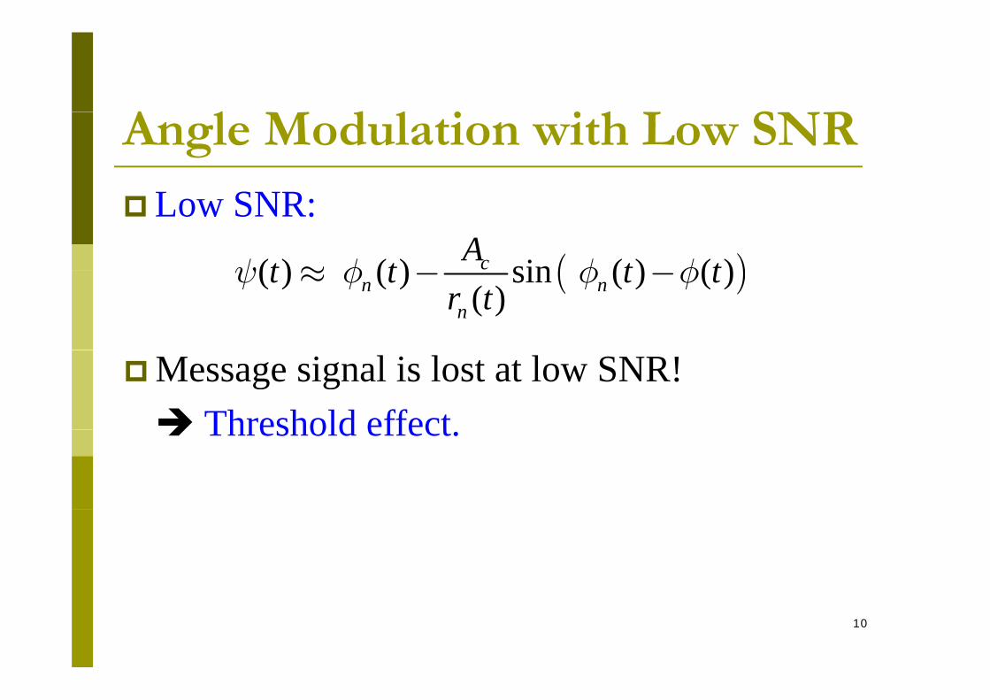
SLow SNR:
( )( ) ( ) sin ( ) ( )cAt t t ty f f f» ( )( ) ( ) sin ( ) ( )( )n n
n
t t t tr t
y f f f» - -
Message signal is lost at low SNR! Threshold effect Threshold effect.
10

A l d l iPhase
Angle Modulation
( )é ù
deviation
High SNR:( )1( ) ( )cos ce t R t t tw q yé ù= + +ë û
High SNR:( ) ( )( )( )( ) ( ) sinn
nr tt t t ty f f f» + - (1)
Low SNR:
( ) ( )( )( ) ( ) ncA
y f f f+ ( )
Small most of the time
( )( ) ( ) sin ( ) ( )( )c
n nAt t t t
r ty f f f» - - (2)
( )nr t
Note: Eq (2) can be obtained from (1) by switching11( ) ( ), and ( ).n c nt t A r tf f« «

Outline
Noise in Angle Modulation Phase deviation
Large SNR Small SNR
O SNR Output SNR PM FM FM
12
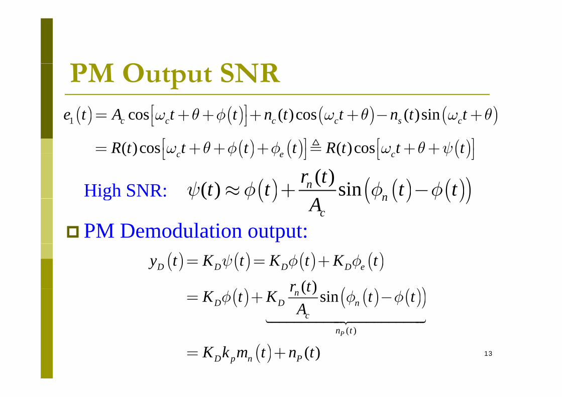
O S RPM Output SNR( ) ( ) ( ) ( )( ) ( ) iq f q qé ù( ) ( ) ( ) ( )1 cos ( )cos ( )sinc c c c s ce t A t t n t t n t tw q f w q w qé ù= + + + + - +ë û
( ) ( ) ( )( )cos ( )cosc e cR t t t t R t t tw q f f w q yé ù é ù= + + + + +ë û ë û( ) ( ) ( )( ) ( )c e cf f y+ + + + +ë û ë û
( ) ( ) ( )( )( )( ) sinnn
r tt t t tA
y f f f» + -High SNR: ( ) ( ) ( )( )( ) ncA
y f f fg
PM Demodulation output:( ) ( ) ( ) ( )
( ) ( ) ( )( )( )D D D D ey t K t K t K t
r ty f f= = +
( ) ( ) ( )( )( )
( ) sin
P
nD D n
cn t
r tK t K t tA
f f f= + -
13( )( )
( )P
D p n PK k m t n t= +
O S RPM Output SNR
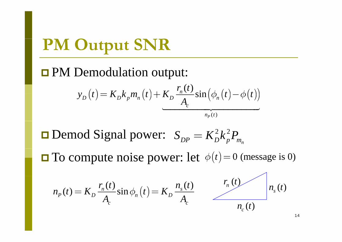
( ) ( ) ( ) ( )( )( ) sinnr ty t K k m t K t tf f= +
PM Demodulation output:( ) ( ) ( ) ( )( )
( )
sin
P
D D p n D nc
n t
y t K k m t K t tA
f f= + -
Demod Signal power: 2 2nDP D p mS K k P=
To compute noise power: let ( ) 0 (message is 0)tf =
( )( ) ( )( ) sinn sP D n D
c c
r t n tn t K t KA A
f= =( )t
( )sn t( )nr t
14
c c ( )cn t
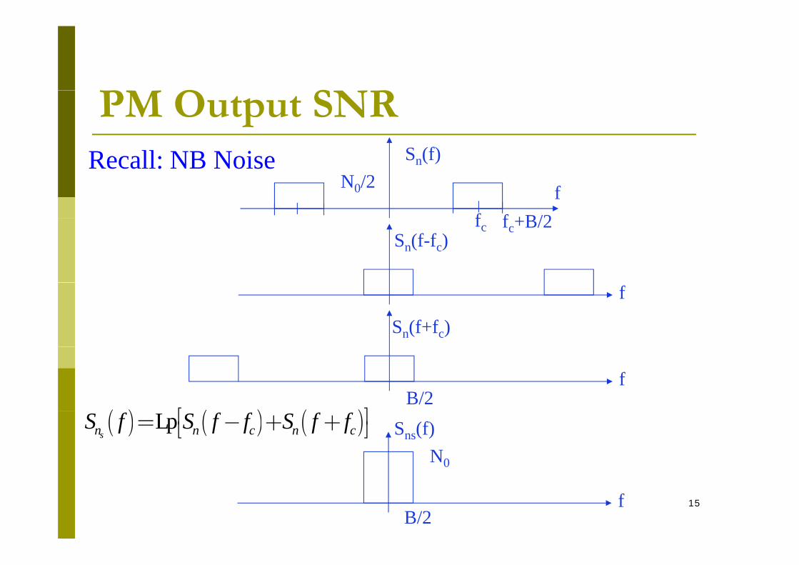
O S RPM Output SNRS (f)R ll NB N i
ff f +B/2
Sn(f)N0/2
Recall: NB Noise
fc fc+B/2Sn(f-fc)
f
Sn(f+fc)
f
( ) ( ) ( )é ùB/2
( ) ( ) ( )Lpsn n c n cS f S f f S f fé ù= - + +ë û Sns(f)
N0
15fB/2
O S RPM Output SNR
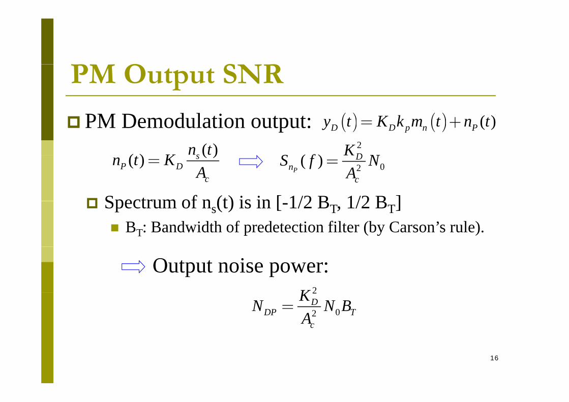
( ) ( ) ( )D D p n Py t K k m t n t= + PM Demodulation output:( )( ) sn tK
2
( ) DKS f N( )( ) s
P Dc
n t KA
= 02( )P
Dn
c
S f NA
=
Spectrum of n (t) is in [ 1/2 B 1/2 B ] Spectrum of ns(t) is in [-1/2 BT, 1/2 BT] BT: Bandwidth of predetection filter (by Carson’s rule).
Output noise power: 2K 2
02D
DP Tc
KN N BA
=
16
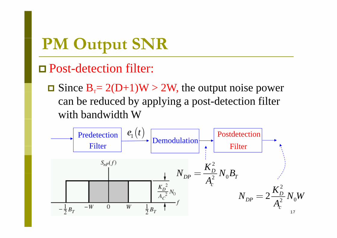
O S RPM Output SNRP t d t ti filt Post-detection filter: Since BT= 2(D+1)W > 2W, the output noise power T ( ) , p p
can be reduced by applying a post-detection filter with bandwidth W
PredetectionFilter
( )1e tDemodulation
FilterPostdetection
Filter Filter
2DKN N B=
2
022 DDP
KN N WA
=
02DP Tc
N N BA
=
17
02DPcA
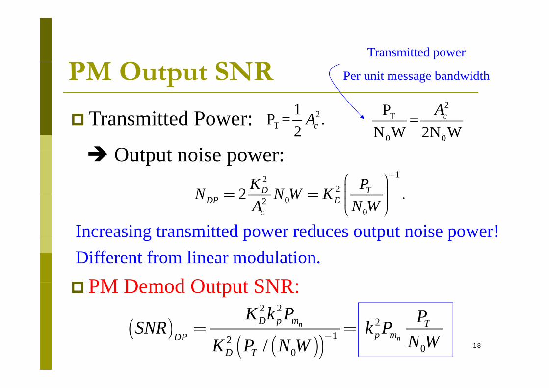
O S RTransmitted power
PM Output SNR1 2P A
Per unit message bandwidth
Transmitted Power: 2T
1P = .2 cA
O t t i
2T
0 0
P =N W 2N W
cA
1222 D TK PN N W K
-æ ö÷ç= = ÷ç
Output noise power:
020
2 .DP Dc
N N W KA N W
= = ÷ç ÷ç ÷è ø
Increasing transmitted power reduces output noise power!g p p pDifferent from linear modulation. PM D d O t t SNR
( )2 2
2nD p m TK k P PSNR k P
PM Demod Output SNR:
18
( )( )( ) 12
00/n
n
p Tp mDP
D T
SNR k PN WK P N W
-= =

O S RPM Output SNR( ) ( )é ù
( ) 2 TPSNR k P= PM Demod Output SNR:( ) ( )PM: cosc c c p nx t A t k m twé ù= +ë û
( )0
np mDPSNR k P
N W PM Demod Output SNR:
( ) sin or cosm mm t t tw w=Single-tone Modulation
: Modulation Indexpkb ( ) sin sinp m mt k t tf w b w=
P( ) 2
0
: increasing increases output SNR.n
TmDP
PSNR PN W
b b=
( )B t b d idth 2 1 i l i dB Wb+( )But bandwidth 2 1 is also increased.TB Wb= +
Input noise power will be increased.
19Eventually large input SNR assumption is invalid threshold effect.
Outline
Noise in Angle Modulation Phase deviation
Large SNR Small SNR
O SNR Output SNR PM FM FM
20
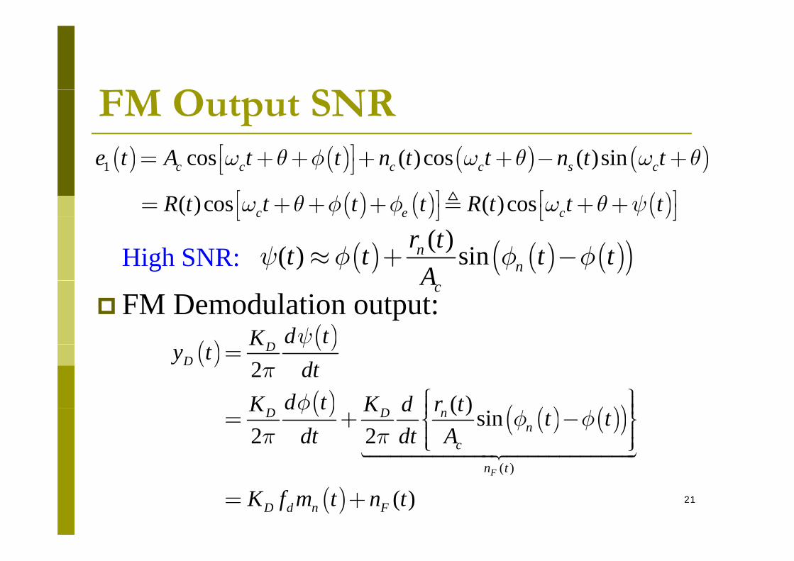
O S RFM Output SNR( ) ( ) ( ) ( )( ) ( ) it A t t t t t tq f q qé ù+ + + + +( ) ( ) ( ) ( )1 cos ( )cos ( )sinc c c c s ce t A t t n t t n t tw q f w q w qé ù= + + + + - +ë û
( ) ( ) ( )( )cos ( )cosc e cR t t t t R t t tw q f f w q yé ù é ù= + + + + +ë û ë û( ) ( ) ( )c e cë û ë û
( ) ( ) ( )( )( )( ) sinnn
r tt t t tA
y f f f» + -High SNR:
FM Demodulation output:( )
( )D d tK y
cA
( )( )
( )( ) ( )( )
2( )
DD
Ky tdt
d t r tK K d
yp
f
=
ì üï ïï ï( )( ) ( )( )
( )
( ) sin2 2
F
nD Dn
c
n t
d t r tK K d t tdt dt Af
f fp p
ï ï= + -í ýï ïï ïî þ
21( )( )
( )Fn t
D d n FK f m t n t= +
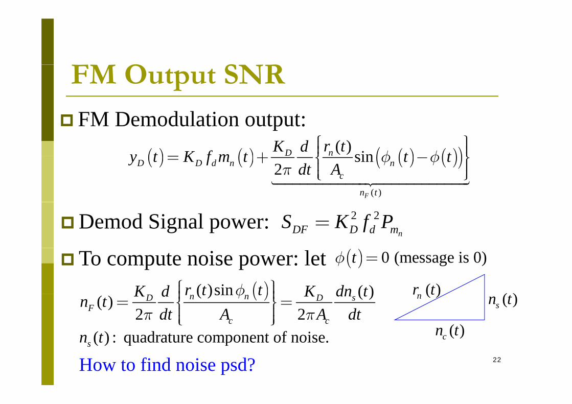
O S RFM Output SNR
FM Demodulation output:
( ) ( ) ( ) ( )( )( ) sinnD r tK dy t K f m t t tf fì üï ïï ï= + í ý( ) ( ) ( ) ( )( )
( )
sin2
F
D D d n nc
n t
y t K f m t t tdt A
f fp
= + -í ýï ïï ïî þ
Demod Signal power: 2 2nDF D d mS K f P=
To compute noise power: let ( ) 0 (message is 0)tf =
( )( )r t( )( )sin ( )r t t dn tK Kd fì üï ïï ï
( )cn t
( )sn t( )nr t( )( )sin ( )( )2 2
n n sD DF
c c
r t t dn tK Kdn tdt A A dt
fp p
ï ï= =í ýï ïï ïî þ( ) : quadrature component of noisen t
22How to find noise psd?( ) : quadrature component of noise.sn t
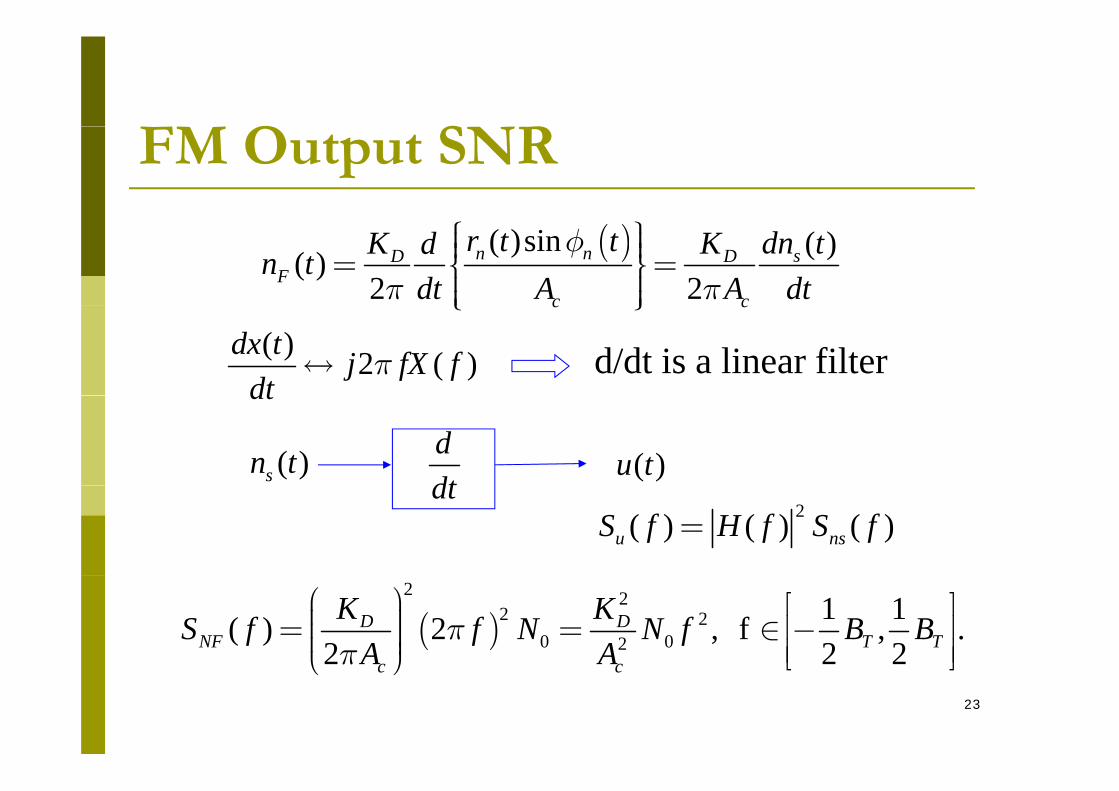
O S RFM Output SNR
( )( )sin ( )( )2 2
n n sD DF
c c
r t t dn tK Kdn tdt A A dt
fp p
ì üï ïï ï= =í ýï ïï ïî þc cî þ( ) 2 ( )dx t j fX f
dtp« d/dt is a linear filter
( )sn t ddt
( )u t
dt
dt2( ) ( ) ( )u nsS f H f S f=
( )2 2
2 20 02
1 1( ) 2 , f , .2 2 2
D DNF T T
c c
K KS f f N N f B BA A
pp
æ ö é ù÷ç= = Î -ê ú÷ç ÷ç ÷ ê úè ø ë û23
c cè ø ë û
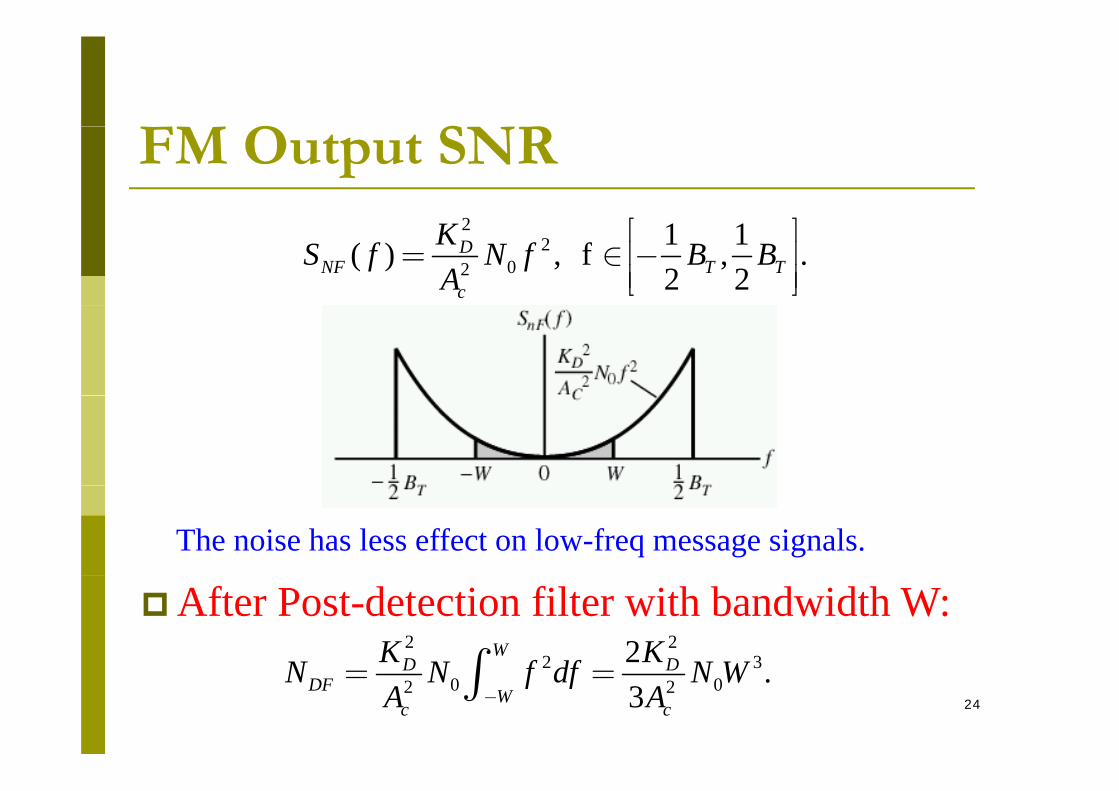
O S RFM Output SNR2
202
1 1( ) , f , .2 2
DNF T T
c
KS f N f B BA
é ù= Î -ê ú
ê úë û
The noise has less effect on low-freq message signals.
After Post-detection filter with bandwidth W:2 2
2 32WD DK KN N f df N Wò
24
2 30 02 2 .
3D D
DF Wc c
N N f df N WA A-
= =ò
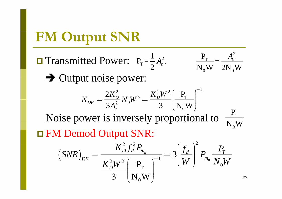
O S RFM Output SNR1 2P A
Transmitted Power: 2T
1P = .2 cA
Output noise power:
2T
0 0
P =N W 2N W
cA
Output noise power: 12 2 2
3 T2 PD DK K WN N W-æ ö÷ç= = ÷ç
Noise power is inversely proportional to TPN W
0203 3 N WDF
c
N N WA
= = ÷ç ÷ç ÷è ø
p y p p0N W
22 2K f P æ ö FM Demod Output SNR:
( )22 2
12 20T
3P
n
n
D d m d TmDF
D
K f P f PSNR PW N WK W
-
æ ö÷ç= = ÷ç ÷ç ÷æ ö è ø÷ç25
T
03 N WD
è ø÷ç ÷ç ÷ç ÷è ø
O S RFM Output SNR
( )2
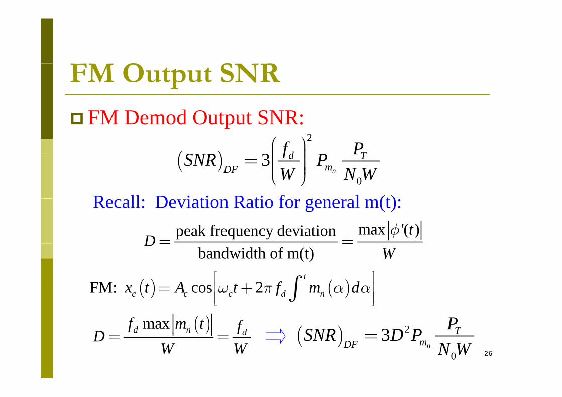
3 d Tf PSæ ö÷ç
FM Demod Output SNR:
( )0
3n
d TmDF
f PSNR PW N W
÷ç= ÷ç ÷ç ÷è øR ll D i ti R ti f l (t)
max '( )peak frequency deviation tD
f= =
Recall: Deviation Ratio for general m(t):
bandwidth of m(t)D
W= =
( ) ( )FM: cos 2t
x t A t f m dw p a aé ù= +ê úò
( )maxd n df m t fD
( ) ( )FM: cos 2c c c d nx t A t f m dw p a a= +ê úê úë ûò
( ) 23 TPSNR D P26
( ) dfDW W
= = ( )0
3n
TmDF
SNR D PN W
=

O S RFM Output SNR
FM Demod Output SNR:
( ) 23 TPSNR D P( ) 2
0
3n
TmDF
SNR D PN W
=
F D 1 B 2(D+1)W 2DW TFor D 1, B =2(D+1)W 2DW:»
( )23 T TB PSNR P
æ ö÷ç= ÷( )04 nmDF
SNR PW N W
ç= ÷ç ÷çè ø
Increasing bandwidth can improve the output SNRInput noise power will be increased.
Increasing bandwidth can improve the output SNR.
27
Eventually large input SNR assumption is invalid threshold effect.
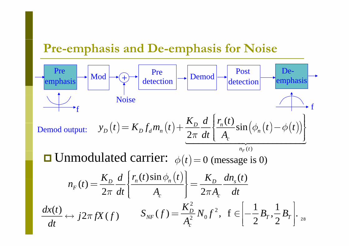
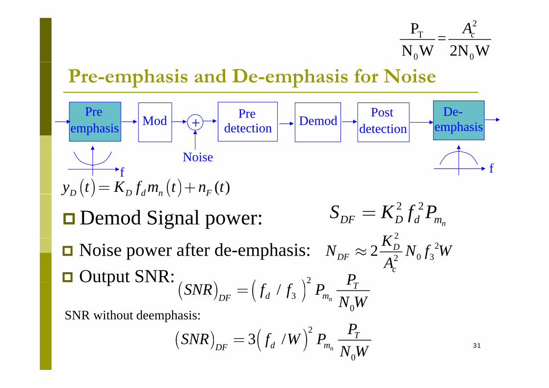
Pre-emphasis and De-emphasis for Noise
+ Pre DemoddetectionPost
detectionModPre
emphasisDe-
emphasis
( ) ( ) ( ) ( )( )( )D r tK d ì üï ïï ï
Noise f f
( ) ( ) ( ) ( )( )( )
( ) sin2
F
nDD D d n n
c
n t
r tK dy t K f m t t tdt A
f fp
ï ï= + -í ýï ïï ïî þDemod output:
Unmodulated carrier: ( )F
( ) 0 (message is 0)tf =
( )( )sin ( )r t t dn tK Kd fì üï ïï ï( )( )sin ( )( )2 2
n n sD DF
c c
r t t dn tK Kdn tdt A A dt
fp p
ï ï= =í ýï ïï ïî þ2 1 1K é ù( )d
28
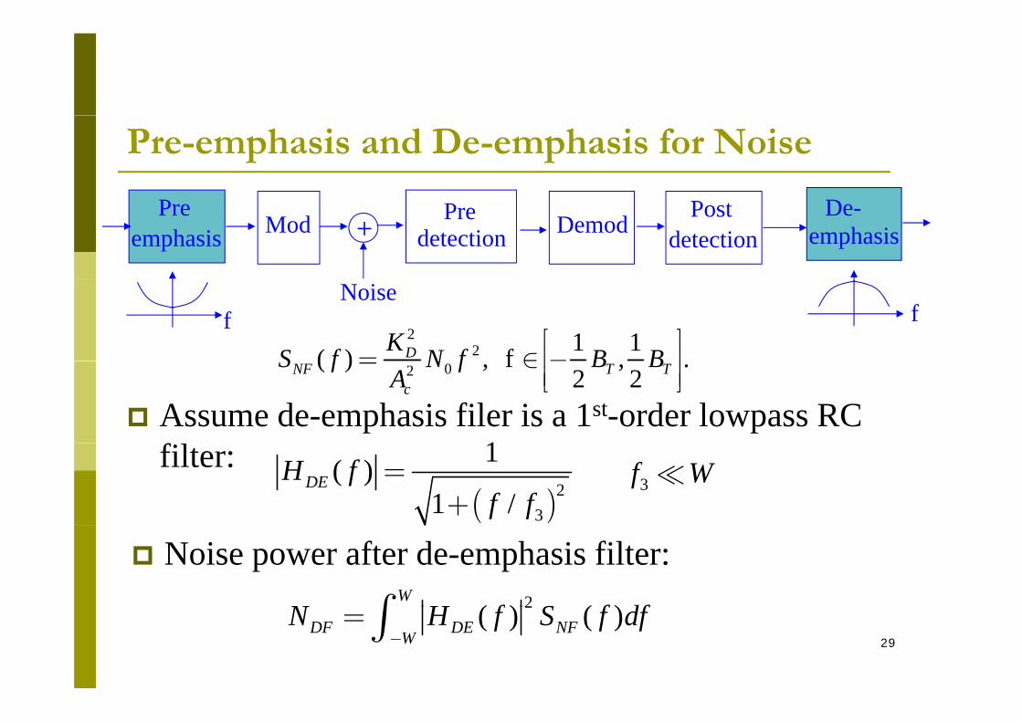
202
1 1( ) , f , .2 2
DNF T T
c
KS f N f B BA
é ù= Î -ê ú
ê úë û( ) 2 ( )dx t j fX f
dtp«
Pre-emphasis and De-emphasis for Noise
+ Pre DemoddetectionPost
detectionModPre
emphasisDe-
emphasis
22 1 1( ) fDKS f N f B B
é ù= Î -ê ú
Noise f f
02( ) , f , .2 2
NF T Tc
S f N f B BA
= Î ê úê úë û
Assume de-emphasis filer is a 1st-order lowpass RC 1filter:( )2
3
1( )1 /
DEH ff f
=+
3f W
Noise power after de-emphasis filter:2( ) ( )
WN H f S f dfò
29
2( ) ( )DF DE NFWN H f S f df
-= ò
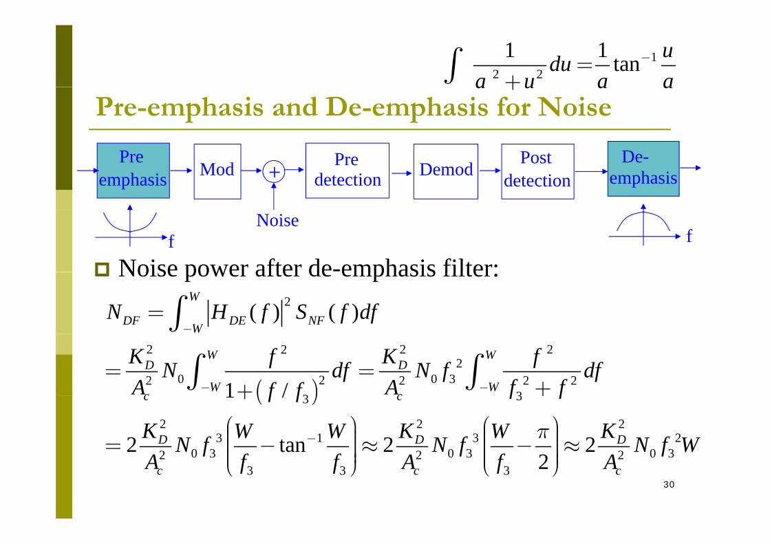
12 2
1 1 tan udua u a a
-=+ò
Pre-emphasis and De-emphasis for Noisea u a a+
+ Pre DemoddetectionPost
detectionModPre
emphasisDe-
emphasis
Noise power after de-emphasis filter:
Noise f f
Noise power after de emphasis filter:2( ) ( )
W
DF DE NFWN H f S f df
-= ò
( )
2 2 222
0 0 322 2 2 2331 /
W WD D
W Wc c
K K ffN df N f dfA A f ff f- -
= =++ò ò( ) 33
2 2 23 1 3 2
0 3 0 3 0 32 2 2
1 /
2 tan 2 22
c c
D D D
f ff f
K K KW W WN f N f N f WA f f A f A
p-
++
æ ö æ ö÷ ÷ç ç= - » - »÷ ÷ç ç÷ ÷ç ç÷ ÷30
0 3 0 3 0 32 2 23 3 3 2c c cA f f A f A÷ ÷ç ç÷ ÷è ø è ø
2T
0 0
P =N W 2N W
cA
Pre-emphasis and De-emphasis for Noise
+ Pre DemoddetectionPost
detectionModPre
emphasisDe-
emphasis
( ) ( ) ( )D D d n Fy t K f m t n t= +
Noise f f
2KDemod Signal power:
2 2nDF D d mS K f P=
( ) ( ) ( )D D d n Fy f
Noise power after de-emphasis: Output SNR:
22
0 322 DDF
c
KN N f WA
»
( ) ( )2 P Output SNR:( ) ( )2
30
/n
Td mDF
PSNR f f PN W
=
PSNR without deemphasis:
31( ) ( )2
0
3 /n
Td mDF
PSNR f W PN W
=
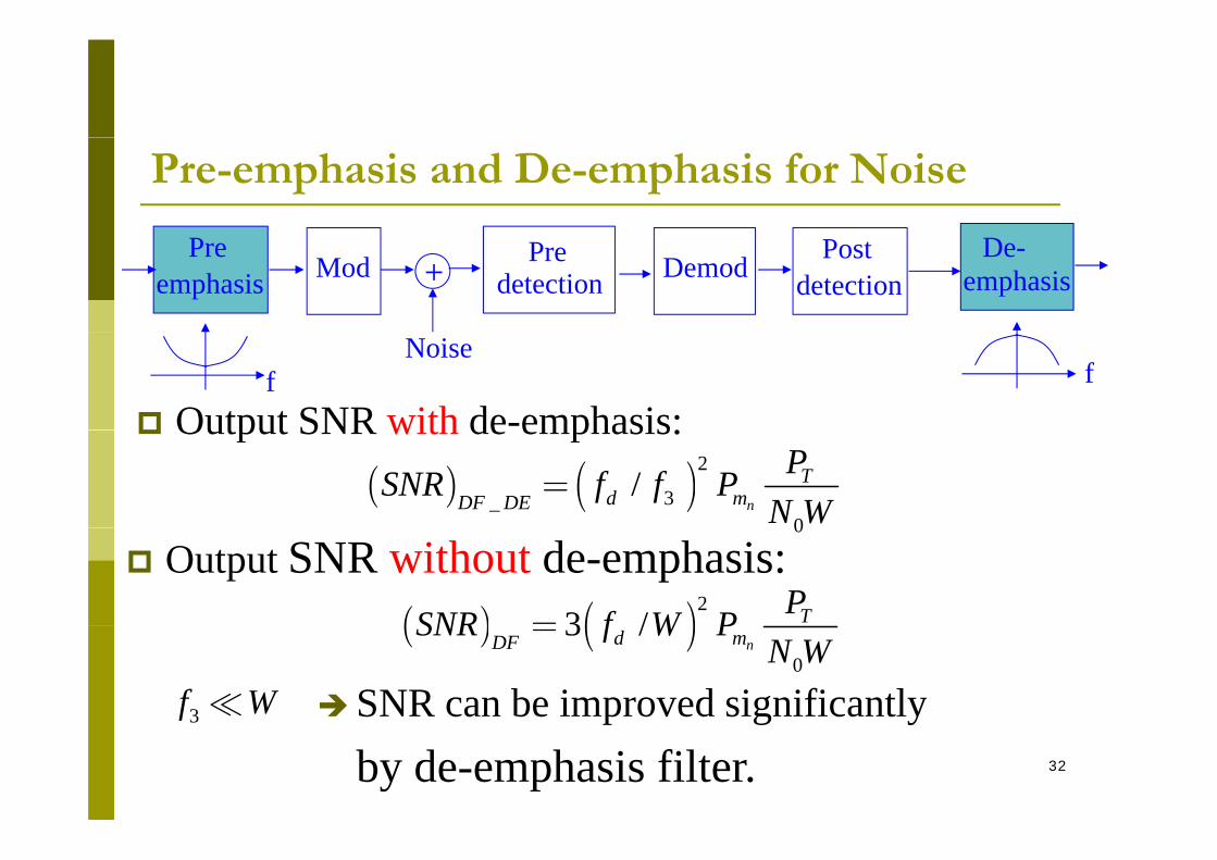
Pre-emphasis and De-emphasis for Noise
+ Pre DemoddetectionPost
detectionModPre
emphasisDe-
emphasis
Output SNR with de-emphasis:
Noise f f
Output SNR with de emphasis:( ) ( )2
3_0
/n
Td mDF DE
PSNR f f PN W
=0
Output SNR without de-emphasis:( ) ( )2
3 / TPSNR f W P=
SNR can be improved significantly3f W
( ) ( )0
3 /nd mDF
SNR f W PN W
=
32
p g yby de-emphasis filter.
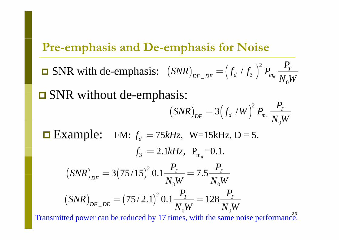
Pre-emphasis and De-emphasis for Noise
( )2 P SNR with de-emphasis:
SNR ith t d h i
( ) ( )2
3_0
/n
Td mDF DE
PSNR f f PN W
=
SNR without de-emphasis:( ) ( )2
3 /n
Td mDF
PSNR f W PN W
=
Example: FM: 75 , W=15kHz, D = 5.df kHz=0N W
n3 m 2.1 , P =0.1.f kHz=
( ) ( )23 75/15 0 1 7 5T TP PSNR = =
( ) ( )275 / 2.1 0.1 128T TP PSNR = =
( ) ( )0 0
3 75/15 0.1 7.5DF
SNRN W N W
= =
33
( ) ( )_0 0
75 / 2.1 0.1 128DF DE
SNRN W N W
Transmitted power can be reduced by 17 times, with the same noise performance.