Embed Size (px)
Citation preview
RADIOENGINEERING, VOL. 26, NO. 4, DECEMBER 2017 917
DOI: 10.13164/re.2017.0917 FEATURE ARTICLE
Compact Bioimplantable MICS and ISM Band Antenna Design for Wireless Biotelemetry Applications
Merih PALANDOKEN
Dept. of Electrical and Electronics Engineering, University of Izmir Katip Celebi, 35620, Izmir, Turkey
Submitted September 19, 2017 / Accepted September 19, 2017
Abstract. A compact dual-band bioimplantable antenna with novel resonator geometry is designed for dual-band wireless biotelemetry applications in MICS and ISM bands. The radiating element geometry is based on an L-shaped transmission line fed anti-spiral resonator struc-ture, which is loaded with the spiral resonator at the end to increase the effective electrical length. The effect of reso-nator geometric parameters on the return loss is discussed with the inclusion of three layered lossy human model in the numerical calculations. The footprint size of the opti-mized bioimplantable antenna is 15 15 1.92 mm3, having the total surface area of λ0/20 λ0/20, where λ0 is the free space wavelength at 403 MHz in MICS band. The compact dual-band antenna has the impedance bandwidth of 24.81% at 403 MHz and 14.7% at 2.45 GHz with the gain values –12.25 dBi and –12.4 dBi in MICS and ISM bands, respectively. The average SAR values at the reso-nance frequencies are numerically computed to find out the input power delivered to the antenna for the reliable oper-ation. The radiation parameters and 3D radiation patterns indicate the potential use of the proposed implantable antenna with the permissible gain in dual-band wireless biotelemetry applications.
Keywords Dual-band bioimplantable antennas, MICS and ISM bands, human body model, electrically small resonator
1. Introduction During the last decades, the ever-evolving miniaturi-
zation of wireless portable electronic devices with increasing multiple functionalities has received great atten-tion in the wide variety of different technological applica-tions. One important application field of wireless commu-nication technologies is the biotelemetry application.
In the biomedical domain, the bioimplanted device located inside the human body by the surgical operations has the main functionality of performing the various diag-nostic and therapeutic functions to transmit the biological
and physiological signals robustly to the exterior monitor-ing and controlling unit in the health care system [1]. Therefore, the miniaturized electrically small antenna is the key component of medical implant device (MID) in the wireless telemetry applications. While the main concern of biotelemetry application is the human health care, the im-plantable antennas have to be specifically designed satis-fying the various physical and biological constraints inside the human body in addition to RF electrical regulations of FCC (Federal Communications Commission) for the im-planted devices [2]. The ITU-R Recommendation SA.1346 [3] has outlined the pre-allocated frequency band of (402 to 405) MHz frequency band for Medical Implant Commu-nication Service (MICS), regulated by FCC [4] and ERC (European Radio-Communication Commission) [5]. The frequency bands of (433.1–434.8) MHz, (868–868.6) MHz and (902.8–928) MHz are also available to be used in the biotelemetry applications in addition to the ISM band (2.4 to 2.5) GHz for the implantable medical devices [6]. Be-cause the human body is electrically lossy in nature with the different tissues of frequency dependent variable per-mittivity and conductivity in the physical structural form, the implanted antenna has to be operated in the layered lossy media of frequency dispersive material parameters. The electrical field radiated from the implanted antenna and the accompanying magnetic field result the mobile charges in the lossy tissues to experience the Lorentz force with the unwanted heating effect of the tissues. The spe-cific absorption rate (SAR) of the human tissues is re-stricted to 2 W/kg in 10 g and 1.6 W/kg in 1 g averaged tissue for the general public exposure in IEEE C95.1-2005 [7] and IEEE C95.1-1999 [8] standards, respectively. This design criterion has to be taken into account to determine the communication link margin.
Many research groups have been working in the field of implantable antennas for the realization of wearable wireless medical telemetry systems. The miniaturization methodologies applicable in the implantable antenna de-sign are the use of CPW fed tapered slot radiators on high dielectric substrates, RO3210, with SMP connector type to reduce the antenna overall size for Medical Device Radio-communication Service (MedRadio) band [9], folded me-ander PIFA structure with the short circuiting of PIFA geometry on one substrate side to the meander line geome-
918 M. PALANDOKEN, COMPACT BIOIMPLANTABLE MICS AND ISM BAND ANTENNA DESIGN FOR WIRELESS BIOTELEMETRY …
try on the other side for extending the radiating main branches into a spiral shape [10], meandered line dipole radiator with an additional superstrate layer on the sub-strate for preserving the required biocompatibility [11], [6]. In [12], a conformal miniaturized multilayered spiral an-tenna is designed for the subcutaneous implantation to have dual-band operation in MedRadio and ISM bands. A compact, probe-fed, broadband implantable antenna based on the patch geometry is also designed for single ISM band biomedical telemetry applications with the cir-cular polarization capability [8], [13]. In [7], an Egret-Beak shaped patch with the shorting pin connected from the radiating patch to the ground plane is designed for the triband operation in MICS, wireless medical telemetry service (WMTS) and ISM bands in wireless medical te-lemetry applications. The metamaterial inspired geometric structures can also be utilized for the antenna miniaturiza-tion to design compact, multifrequency, high gain and efficient implantable antennas as in different RF applica-tions [14–16].
In this paper, a novel, compact, implantable dual-band antenna is designed to operate in MICS and ISM bands by taking the lossy human phantom model into ac-count for better RF performance evaluation in further clini-cal tests. The paper is organized in the following manner. The novel electrically small resonator geometry is ex-plained in Sec. 2 with the design principle. In Sec. 3, the numerical and experimental results of the implantable an-tenna model are illustrated with the reflection coefficients of the proposed antenna in human body model and free space to figure out the requirement of human body model in the numerical simulations. The surface current distribu-tions are shown to understand the antenna operation prin-ciple. The different geometrical parameters of the resonator structure are studied parametrically to point out the design methodology in the optimization process in Sec. 4. In Sec. 5, the antenna radiation patterns and SAR results are illustrated to determine the RF specifications of the bio-implantable transceiver module. The concluding remarks are conducted in Sec. 6.
2. Bioimplantable Antenna Design The proposed compact dual-band bioimplantable
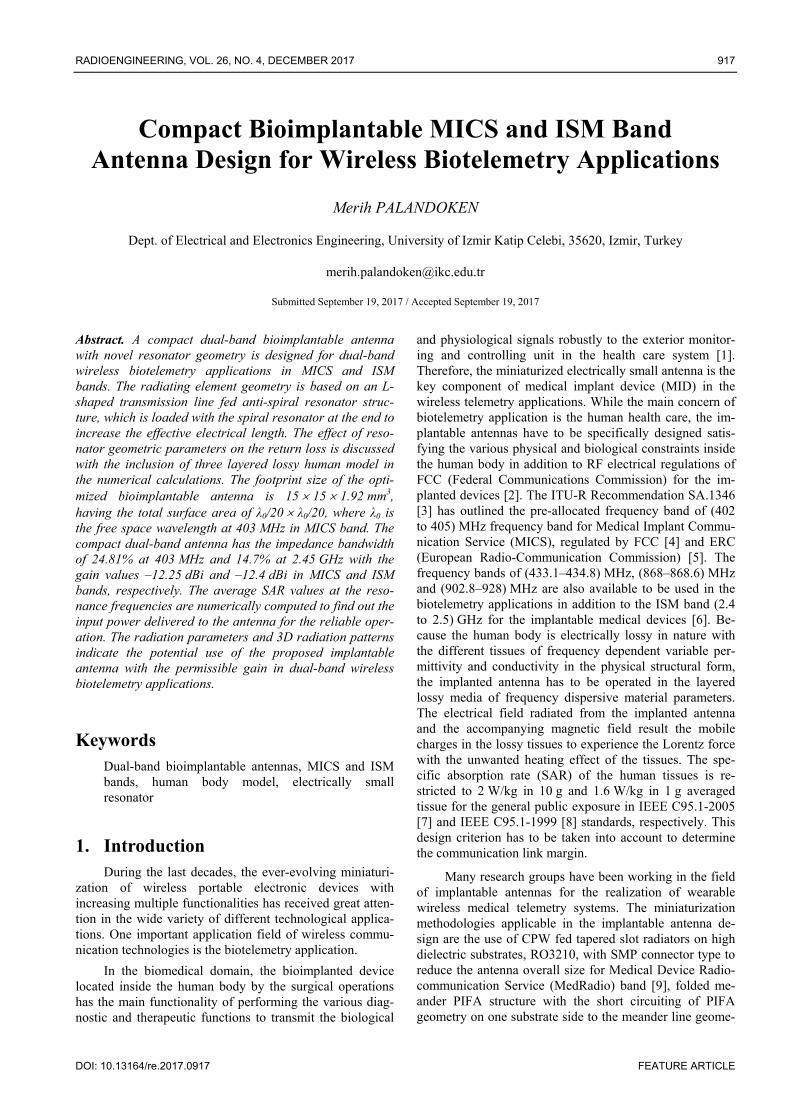
antenna model is shown in Fig. 1 along with the geometric parameters. The electrically small resonator model is based on the extended L-shaped direct feeding of anti-spiral res-onator structure loaded with the spiral resonator at the end in order to increase the electrical length for the lower band resonant operation. The anti-spiral resonator geometry loaded with the spiral resonator is indicated by the circle in Fig. 1. The L-shaped feeding line is effective for the reso-nant length in the lower frequency band due to the trans-mission line loading of anti-spiral resonator for the increased electrical length. The lower substrate side is fully metallized with 18 µm thick copper for the ground plane. Because the bioimplantable antennas have to be located in-
(a)
(b)
Fig. 1. (a) Numerical model of dual-band bioimplantable an-tenna with the geometric parameters of W1 = 11.3 mm, W2 = 9 mm, W3 = 5 mm, W4 = 8 mm, W5 = 0.8 mm, Wsub = 15 mm, Wdis = 2.5 mm, L1 = 9.5 mm, L2 = 11 mm, L3 = 6.5 mm, L4 = 4.5 mm, L5 = 5.5 mm, Lsub = 15 mm, Ldisp = 4 mm. (b) Fabricated dual-band bioim-plantable antenna prototype.
side the conductive human tissue, the lower and upper substrate sides have to be prevented from being short-cir-cuited by the use of dielectric biocompatible superstrates. The substrate and superstrate materials are selected as 0.64 mm thick Rogers 3210 low loss dielectric material with the relative permittivity of 10.2 and loss tangent of 0.003. The whole antenna size is 15 15 1.92 mm3, with the surface area of λ0/20 λ0/20, where λ0 is the free space wavelength at the lower resonance frequency. The stepped impedance line at the feeding port has 1 mm width and 3 mm length to facilitate the soldering of twisted stripped cable U.FL connector. The transmission line width and the distance between any two transmission line sections are 0.5 mm. In the numerical model, the geometric parameters of the electrically small resonator are optimized to have the resonance frequencies in MICS (402–405) MHz and ISM band (2.4–2.5) GHz with the reflection coefficients better than –25 dB. The higher order modes to be excited at the higher frequencies have negligible effect on the signal propagation through the surrounding lossy body tissues due to the high reflection coefficients. The additional high frequency filtering sections based on the distributed trans-mission lines can be alternatively added into the resonator
RADIOENGINEERING, VOL. 26, NO. 4, DECEMBER 2017 919
geometry to filter out the higher order resonance or cou-pled modes with the expense of larger antenna size and fabrication complexity in the limited space [17], [18].
3. Numerical and Experimental Results The numerical model of compact dual-band bioim-
plantable antenna has been numerically computed in three layered human body model, composed of skin, fat and muscle layers to optimize the resonator geometric parame-ters. The 3D fullwave electromagnetic field computations are done in FEM based commercial electromagnetic field solver Ansoft HFSS. The three layered human body model is shown in Fig. 2 along with the finite thicknesses of each layer. The lossy dielectric and density material parameters are listed in Tab. 1. The bioimplantable antenna is located inside the muscle layer with the separation distance of 2 mm from the lower edge of the fat layer.
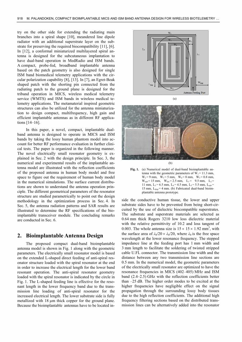
In addition to the numerical calculations in the human body model to optimize the reflection coefficients for MICS and ISM operation bands, the numerical and ex-perimental results are obtained to figure out RF perfor-mance differences inside the body and outside the body in free space. The reflection coefficients of the fabricated bioimplantable antenna have been measured by Agilent N9912A VNA in free space. The measured and simulated reflection parameters in free space and numerically com-puted S11 in three layered lossy human model are shown in Fig. 3. As shown in Fig. 3, even though the resonance frequencies can be observed in the numerical computation and experimental measurement results for the proposed bioimplantable antenna in free space, the reflection coeffi-cients are high in the range of –2 dB, which are not suitable to be used in any kind of wireless radio communication applications. The numerical and experimental results are in
Fig. 2. Three layered human body model.
Material Model
Relative Dielectric Constant
σ [S/m] Density [kg/m3]
Thickness [mm]
Skin layer 38.01 1.46 1100 2 Fat layer 5.28 0.1 909.4 4
Muscle layer 52.73 1.73 1040 28
Tab. 1. Dielectric and density material parameters of the layered human body model [19].
good agreement for the proposed antenna model in free space. However, because the antenna model optimization has been done by taking the antenna location inside the layered lossy human body model into account in the nu-merical modelling, S11 is very low as intended in the lower frequency band, which is better than –10 dB between 350 MHz and 450 MHz covering the whole MICS band with 25 dB return loss at 403 MHz. For the higher fre-quency band, S11 is lower than –10 dB in the frequency band of 2.22 GHz and 2.58 GHz with the minimum reflec-tion parameters better than –40 dB in two resonance fre-quencies of 2.34 GHz and 2.45 GHz, covering the whole ISM band. The higher order resonance frequencies occur-ring at the frequencies of 750 MHz, 980 MHz, 1.45 MHz and 1.98 MHz have higher reflection coefficients than those at the resonance frequencies of interest in MICS and ISM bands.
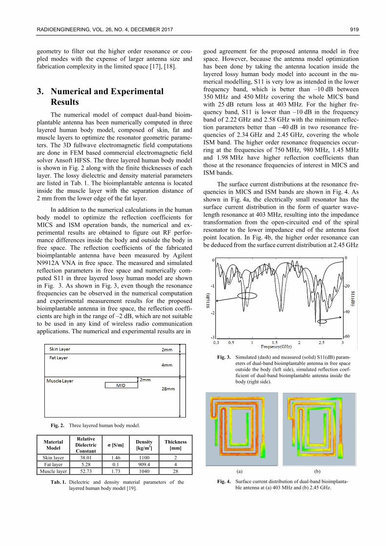
The surface current distributions at the resonance fre-quencies in MICS and ISM bands are shown in Fig. 4. As shown in Fig. 4a, the electrically small resonator has the surface current distribution in the form of quarter wave-length resonance at 403 MHz, resulting into the impedance transformation from the open-circuited end of the spiral resonator to the lower impedance end of the antenna foot point location. In Fig. 4b, the higher order resonance can be deduced from the surface current distribution at 2.45 GHz
Fig. 3. Simulated (dash) and measured (solid) S11(dB) param-
eters of dual-band bioimplantable antenna in free space outside the body (left side), simulated reflection coef-ficient of dual-band bioimplantable antenna inside the body (right side).
(a) (b)
Fig. 4. Surface current distribution of dual-band bioimplanta-ble antenna at (a) 403 MHz and (b) 2.45 GHz.
920 M. PALANDOKEN, COMPACT BIOIMPLANTABLE MICS AND ISM BAND ANTENNA DESIGN FOR WIRELESS BIOTELEMETRY …
due to the excitation of different resonator sections with four effective current nulls in the higher frequency band. To have the antenna resonances at the desired frequencies with the lowest reflection coefficients is not the only im-portant design criterion. Permissible signal reception to and transmission from the bioimplantable sensor module in the biotelemetry systems are also important RF system param-eters to be investigated with the possibly high radiation efficiency.
4. Numerical Parametric Studies In the bioimplantable antenna design for the biotele-
metry applications, it is very important to reduce the an-tenna size in an effective manner in order for the antenna to be placed inside the encapsulated bioimplanted transceiver RF electronics module. It is therefore crucial to compute the antenna performance parameters inside the conductive human body with the lossy dielectric material properties. Therefore, the numerical parametric studies in the proposed bioimplantable antenna model are done for the optimiza-tion of RF antenna performance. As a starting point to determine the resonant antenna length at the lower fre-quency band, the total line length from the feeding line to the end of the spiral resonator is taken to be equal to λg/4, where λg is the guided wavelength in the substrate [17, 20] as it can be deduced from the surface current distribution in Fig. 4a. The total length of extended L-shaped feeding line, anti-spiral resonator and spiral resonator sections are para-metrically changed to satisfy the input impedance at MICS and ISM bands for the final prototype. Therefore, three geometric parameters, Ldisp, L4 and L3 are numerically studied to figure out the effect of antenna geometry on the resonance frequency in this section.
4.1 Displacement Length between Antispiral Resonator and Substrate Edge
The first geometric parameter to be numerically studied is the displacement distance between the extended length of anti-spiral resonator and lower substrate edge
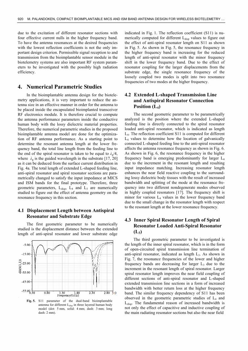
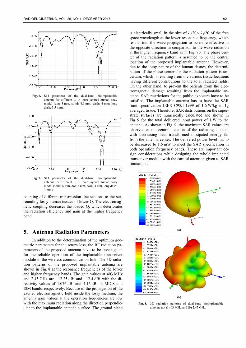
Fig. 5. S11 parameter of the dual-band bioimplantable
antenna for different Ldisp in three layered human body model (dot: 5 mm, solid: 4 mm; dash: 3 mm; long dash: 2 mm).
indicated in Fig. 1. The reflection coefficient (S11) is nu-merically computed for different Ldisp values to figure out the effect of anti-spiral resonator length on S11 as shown in Fig. 5. As shown in Fig. 5, the resonance frequency in the higher frequency band is increasing for the reduced length of anti-spiral resonator with the minor frequency shift in the lower frequency band. Due to the effect of resonator coupling for the larger displacements from the substrate edge, the single resonance frequency of the loosely coupled two modes is split into two resonance frequencies of two modes at the higher frequency.
4.2 Extended L-shaped Transmission Line and Antispiral Resonator Connection Position (L4)
The second geometric parameter to be parametrically analyzed is the position where the extended L-shaped feeding line is directly connected to the spiral resonator loaded anti-spiral resonator, which is indicated as length L4. The reflection coefficient S11 is computed for different L4 values to determine how the location of galvanically connected L-shaped feeding line to the anti-spiral resonator affects the antenna resonance frequency as shown in Fig. 6. As shown in Fig. 6, the resonance frequency in the higher frequency band is emerging predominantly for larger L4 due to the increment in the resonant length and resulting input impedance matching. Increasing resonator length enhances the near field reactive coupling to the surround-ing lossy dielectric body tissues with the result of increased bandwidth and splitting of the mode at the resonance fre-quency into two different nondegenerate modes observed in highly coupled resonators [17]. The frequency shift is minor for various L4 values in the lower frequency band due to the small change in the resonator length with respect to the resonant length at the lower resonance frequency.
4.3 Inner Spiral Resonator Length of Spiral Resonator Loaded Anti-Spiral Resonator (L3)
The third geometric parameter to be investigated is the length of the inner spiral resonator, which is in the form of open-circuited spiral transmission line termination of anti-spiral resonator, indicated as length L3. As shown in Fig. 7, the resonance frequencies of the lower and higher frequency bands are decreasing for larger L3 due to the increment in the resonant length of spiral resonator. Larger spiral resonator length improves the near field coupling of different sections of anti-spiral resonator and L-shaped extended transmission line sections in a form of increased bandwidth with better return loss at the higher frequency band. The similar frequency dependency of S11 has been observed in the geometric parametric studies of L4 and Ldisp. The fundamental reason of increased bandwidth is not only the effect of capacitive and inductive coupling of the main radiating resonator sections but also the near field
RADIOENGINEERING, VOL. 26, NO. 4, DECEMBER 2017 921
Fig. 6. S11 parameter of the dual-band bioimplantable
antenna for different L4 in three layered human body model (dot: 5 mm, solid: 4.5 mm; dash: 4 mm; long dash: 3.5 mm).
Fig. 7. S11 parameter of the dual-band bioimplantable
antenna for different L3 in three layered human body model (solid: 6 mm, dot: 5 mm, dash: 4 mm, long dash: 3 mm).
coupling of different transmission line sections to the sur-rounding lossy human tissues of lower Q. The electromag-netic coupling decreases the loaded Q, which deteriorates the radiation efficiency and gain at the higher frequency band.
5. Antenna Radiation Parameters In addition to the determination of the optimum geo-
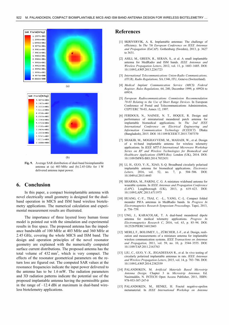
metric parameters for the return loss, the RF radiation pa-rameters of the proposed antenna have to be investigated for the reliable operation of the implantable transceiver module in the wireless communication link. The 3D radia-tion patterns of the proposed implantable antenna are shown in Fig. 8 at the resonance frequencies of the lower and higher frequency bands. The gain values at 403 MHz and 2.45 GHz are –12.25 dBi and –12.4 dBi with the di-rectivity values of 1.076 dBi and 4.16 dBi in MICS and ISM bands, respectively. Because of the propagation of the excited electromagnetic field inside the lossy medium, the antenna gain values at the operation frequencies are low with the maximum radiation along the direction perpendic-ular to the implantable antenna surface. The ground plane
is electrically small in the size of λ0/20 λ0/20 of the free space wavelength at the lower resonance frequency, which results into the wave propagation to be more effective to the opposite direction in comparison to the wave radiation at the higher frequency band as in Fig. 8b. The phase cen-ter of the radiation pattern is assumed to be the central location of the proposed implantable antenna. However, due to the lossy nature of the human tissues, the determi-nation of the phase center for the radiation pattern is un-certain, which is resulting from the various tissue locations having different contributions to the total radiated fields. On the other hand, to prevent the patients from the elec-tromagnetic damage resulting from the implantable an-tenna, SAR restrictions for the public exposure have to be satisfied. The implantable antenna has to have the SAR limit specification IEEE C95.1-1999 of 1.6 W/kg in 1g averaged tissue. Therefore, SAR distributions on the super-strate surfaces are numerically calculated and shown in Fig. 9 for the total delivered input power of 1 W to the antenna. As shown in Fig. 9, the maximum SAR values are observed at the central location of the radiating element with decreasing heat transformed dissipated energy far from the antenna center. The delivered power level has to be decreased to 1.6 mW to meet the SAR specification in both operation frequency bands. These are important de-sign considerations while designing the whole implanted transceiver module with the careful attention given to SAR limitations.
(a)
(b)
Fig. 8. 3D radiation patterns of dual-band bioimplantable antenna at (a) 403 MHz and (b) 2.45 GHz.
922 M. PALANDOKEN, COMPACT BIOIMPLANTABLE MICS AND ISM BAND ANTENNA DESIGN FOR WIRELESS BIOTELEMETRY …
(a)
(b)
Fig. 9. Average SAR distribution of dual-band bioimplantable antenna at (a) 403 MHz and (b) 2.45 GHz for 1 W delivered antenna input power.
6. Conclusion In this paper, a compact bioimplantable antenna with
novel electrically small geometry is designed for the dual-band operation in MICS and ISM band wireless biotele-metry applications. The numerical calculation and experi-mental measurement results are illustrated.
The importance of three layered lossy human tissue model is pointed out with the simulation and experimental results in free space. The proposed antenna has the imped-ance bandwidth of 100 MHz at 403 MHz and 360 MHz at 2.45 GHz, covering the whole MICS and ISM band. The design and operation principles of the novel resonator geometry are explained with the numerically computed surface current distributions. The proposed antenna has the total volume of 432 mm3, which is very compact. The effects of the resonator geometrical parameters on the re-turn loss are figured out. The computed SAR values at the resonance frequencies indicate the input power delivered to the antenna has to be 1.6 mW. The radiation parameters and 3D radiation patterns indicate the potential use of the proposed implantable antenna having the permissible gains in the range of –12.4 dBi at maximum in dual-band wire-less biotelemetry applications.
References
[1] SKRIVERVIK, A. K. Implantable antennas: The challenge of efficiency. In The 7th European Conference on IEEE Antennas and Propagation (EuCAP). Gothenburg (Sweden), 2013, p. 3627 to 3631.
[2] ASILI, M., GREEN, R., SERAN, S., et al. A small implantable antenna for MedRadio and ISM bands. IEEE Antennas and Wireless Propagation Letters, 2012, vol. 11, p. 1683–1685. DOI: 10.1109/LAWP.2013.2241723
[3] International Telecommunications Union-Radio Communications, (ITUR), Radio Regulations, SA.1346, ITU, Geneva (Switzerland).
[4] Medical Implant Communication Service (MICS) Federal Register, Rules Regulations, 64, 240, December 1999, p. 69926 to 69934.
[5] European Radiocommunications Commission Recommendation 70-03 Relating to the Use of Short Range Devices. In European Conference of Postal and Telecommunications Administration, CEPT/ERC 70-03, Annex 12, 1997.
[6] FERDOUS, N., NAINEE, N. T., HOQUE, R. Design and performance of miniaturized meandered patch antenna for implantable biomedical applications. In The 2nd IEEE International Conference on Electrical Engineering and Information Communication Technology (ICEEICT). Dhaka (Bangladesh), 2015. DOI: 10.1109/ICEEICT.2015.7307370
[7] SHAKIB, M., MOGHAVVEMI, M., MAHADI, W., et al. Design of a tri-band implantable antenna for wireless telemetry applications. In IEEE MTT-S International Microwave Workshop Series on RF and Wireless Technologies for Biomedical and Healthcare Applications (IMWS-Bio). London (UK), 2014. DOI: 10.1109/IMWS-BIO.2014.7032451
[8] LI, H., GUO, Y.-X., XIAO, S.-Q. Broadband circularly polarised implantable antenna for biomedical applications. Electronics Letters, 2016, vol. 52, no. 7, p. 504–506. DOI: 10.1049/el.2015.4445
[9] SHARMA, M., PARINI, C. G. A miniature wideband antenna for wearable systems. In IEEE Antennas and Propagation Conference (LAPC). Loughborough (UK), 2013, p. 619–623. DOI: 10.1109/LAPC.2013.6711975
[10] HUANG, C.-Y., TSAI, C. –L., YANG, C.–L. Compact folded meander PIFA antennas in MedRadio bands. In Progress In Electromagnetics Research Symposium Proceedings. Tapei, 2013, p. 756–759.
[11] UNG, J., KARACOLAK, T. A dual-band meandered dipole antenna for medical telemetry applications. Progress In Electromagnetics Research C, 2016, vol. 63, p. 85–94. DOI: 10.2528/PIERC16012603
[12] MERLI, F., BOLOMEY, L., ZÜRCHER, J.-F., et al. Design, reali-zation and measurements of a miniature antenna for implantable wireless communication systems. IEEE Transactions on Antennas and Propagation, 2011, vol. 59, no. 10, p. 3544–3555. DOI: 10.1109/TAP.2011.2163763
[13] LIU, C., GUO, Y.-X., JEGADEESAN R., et al. In vivo testing of circularly polarized implantable antennas in rats. IEEE Antennas and Wireless Propagation Letters, 2015, vol. 14, p. 783–786. DOI: 10.1109/LAWP.2014.2382559
[14] PALANDOKEN, M. Artificial Materials Based Microstrip Antenna Design. Chapter 3 in Microstrip Antennas. Ed. Nasimuddin, N. INTECH Open Access Publisher, 2011, ISBN: 978-953-307-247-0
[15] PALANDOKEN, M., HENKE, H. Fractal negative-epsilon metamaterial. In IEEE International Workshop on Antenna

RADIOENGINEERING, VOL. 26, NO. 4, DECEMBER 2017 923
Technology (iWAT). Lisbon (Portugal), 2010. DOI: 10.1109/IWAT.2010.5464790
[16] PALANDOKEN, M., HENKE, H. Fractal spiral resonator as magnetic metamaterial. In IEEE Applied Electromagnetics Conference (AEMC). Kolkata (India), 2009. DOI: 10.1109/AEMC.2009.5430645
[17] POZAR, D. M. Microwave Engineering. 4th ed., John Wiley & Sons, 2011. ISBN-10: 0470631554
[18] PALANDOKEN, M. Metamaterial-Based Compact Filter Design. Chapter 19 in Metamaterial. Ed. Xun-Ya Jiang. INTECH Open Access Publisher, 2012. ISBN: 978-953-51-0591-6
[19] LOKTONGBAM, P., LAISHRAM, R. Performance and design analysis of an implantable antenna for biotelemetry. International Journal of Scientific and Research Publications, 2017, vol. 7, no. 6, p. 105–114. ISSN: 2250-3153
[20] BALANIS, C. A. Antenna Theory: Analysis and Design. 3rd ed., Wiley-Interscience, 2005. ISBN-13:978-0471667827
About the Author ... Merih PALANDÖKEN was born in Kahramanmaras, Turkey. He received his M.Sc. degree in the field of Mi-crosystem and Microelectronics Engineering from Tech-nische Universitaet Hamburg, Germany in 2005 and Ph.D. degree in the field of Metamaterial Based Antennas and Microwave Filters from the Dept. of Theoretical Electrical Engineering at Technische Universitaet Berlin, Germany in 2012. His research interests include bioimplantable antenna design, RF energy harvesting system design, electromag-netic field theory and electrically small antenna design.


![Broadband Bow-Tie Antenna with Tapered Balun...addition, a reflector is used to increase the antenna gain. In [8] a double side bow-tie antenna designed in ISM band with different](https://img.pdfslide.net/doc/110x75/5e2b84e68a93874095208152/broadband-bow-tie-antenna-with-tapered-balun-addition-a-reflector-is-used-to.jpg)