Embed Size (px)
Citation preview
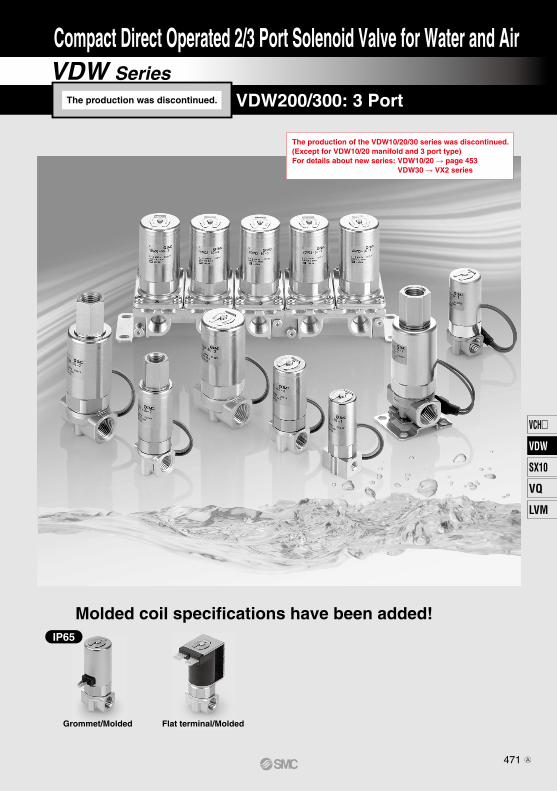
The production of the VDW10/20/30 series was discontinued.(Except for VDW10/20 manifold and 3 port type)For details about new series: VDW10/20 �page 453
VDW30 VX2 series
Grommet/Molded Flat terminal/Molded
Molded coil specifications have been added!IP65
VDW Series
Compact Direct Operated 2/3 Port Solenoid Valve for Water and Air
VDW10/20/30: 2 Port, VDW200/300: 3 PortThe production was discontinued.
471
VCH
VDW
SX10
VQ
LVM
VDW
A

The production of the VDW10/20/30 series was discontinued.(Except for VDW10/20 manifold and 3 port type)For details about new series: VDW10/20 �page 453
VDW30 �VX2 series
VDW SeriesVDW SeriesCompact Direct Operated 2/3 Port Solenoid ValveFor Water and Air
P.473 P.484
Grommet/Molded
High flow rate: Cv factor 0.04 to 0.46 (2 port)
Improved environment resistanceEnvironment resistance is improved by using a molded coil. (Enclosure IP65 or equivalent, grommet mold)
Universal portingVDW200/300 (3 port)
Brass (C37)/Stainless steel manifolds addedto series (2 port)
Clip type
Threaded for bottom mountingSpecial bracket can be mounted.
Threaded assemblySimplifies maintenance.
Improved corrosion resistanceSpecial material introduced
Improved durability (Nearly twice the life of the previous series)
Ease of maintenance has been improved.Changing of the coil is made easy by means of clip design. (2 port)
The use of a unique magnetic material reduces the operating resistance of moving parts, while improving service life, wear and corrosion resistance.
Lineup by Compact Design
VDW10 VDW20 VDW30 VDW200 VDW300
ø17 ø20.5ø28 ø20.5
ø28
ø17 ø20.5ø28 ø20.5
ø282 Port 3 Port
The production was discontinued.
472A
The production of the VDW10/20/30 series was discontinued.(Except for VDW10/20 manifold and 3 port type)For details about new series: VDW10/20 �page 453
VDW30 �VX2 series
1
2
[Option]
Q—
CE-compliant
Nil
CE-compliant
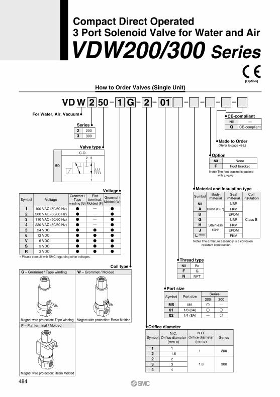
How to Order Valves (Single Unit)
For Water, Air, Vacuum
VD W 2 1 1 G 2 01
123
10
20
30
Series
1
N.C.
Valve type
123456VSR
VoltageSymbol
100 VAC (50/60 Hz)
200 VAC (50/60 Hz)
110 VAC (50/60 Hz)
220 VAC (50/60 Hz)
24 VDC
12 VDC
6 VDC
5 VDC
3 VDC
∗ Please consult with SMC regarding other voltages.
Grommet /Tape
winding (G)
Flatterminal,
Molded (F)
Grommet /Molded (W)
Voltage
102030
Grommet / Tape windingSeries
Series and Coil Type CombinationsFlat terminal / Molded Grommet / Molded
Coil typeG – Grommet / Tape winding
Magnet wire protection: Tape winding
Magnet wire protection: Resin Molded
Magnet wire protection: Resin Molded
F – Flat terminal / Molded
W – Grommet / Molded
12123234
Orifice diameter(mm ø)
Symbol Series
1
1.6
1.6
2.3
3.2
2
3
4
10
20
30
Orifice diameter
M50102
Port sizeSymbolSeries
M5
1/8 (6A)
1/4 (8A)
10
—
—
Port size
20
—
30
—
FN
Rc
G
NPT
Nil
Thread type
Note) The foot bracket is packed with a valve.
FNone
Foot bracket
Nil
Option
Made to Order (Refer to page 474.)
ABGHJ
L Note)
Brass (C37)
Stainlesssteel
Bodymaterial
Symbol
Nil
Material and insulation type
NBR
FKM
EPDM
NBR
FKM
EPDM
FKM
Sealmaterial
Class B
Coilinsulation
Note) The armature assembly is a corrosion resistant construction.
Compact Direct Operated2 Port Solenoid Valve for Water and Air
VDW10/20/30 Series
The production was discontinued.
473
VCH
VDW
SX10
VQ
LVM
VDW
A

Standard Specifications
Valve construction
Fluid Note 2)
Withstand pressure (MPa)
Ambient temperature (°C)
Fluid temperature (°C)
Environment
Valve leakage (cm3/min)
Mounting orientation
Vibration/Impact (m/s2) Note 4)
Rated voltage
Allowable voltage fluctuation (%)
Coil insulation type
Enclosure
Power consumption (W) Note 3)
Grommet / Tape winding
Flat terminal / Molded
Grommet / Molded
Val
ve s
pec
ific
atio
ns
Co
il sp
ecif
icat
ion
s
Direct operated poppet
Water (except waste water or agricultural water), Air, Low vacuum
2.0
–10 to 50
1 to 50 (No freezing)
Location without corrosive or explosive gases
0 (with water pressure) 1 or less (Air)
Unrestricted
30/150
±10% of rated voltage
Class B
Dust-proof (equivalent to IP40)
Dust-tight (equivalent to IP60) Note 5)
Dust-tight / Low jetproof (equivalent to IP65)
2.5 (VDW10), 3 (VDW20/30)
24 VDC, 12 VDC, 6 VDC, 5 VDC, 3 VDC, 100 VAC, 110 VAC, 200 VAC, 220 VAC (50/60 Hz)
Note 1) When used under conditions which may cause condensation on the exterior of the product, select Grommet / Molded.
Note 2) When used with deionized water, select “L” (Stainless steel, FKM) for the material type.Note 3) Since the AC coil specification includes a rectifier element, there is no difference in power consumption
between inrush and holding.In the case of 110/220 VAC, the VDW10 is 3 W and the VDW20/30 is 3.5 W.
Note 4) Vibration resistance ····· No malfunction when tested with one sweep of 5 to 200 Hz in the axial direction and at a right angle to the armature, in both energized and deenergized states. Impact resistance ········ No malfunction when tested with a drop tester in the axial direction and at a right angle to the armature, one time each in energized and deenergized states.Note 5) Since electrical connections are exposed, there is no water resistance.
Characteristic Specifications
Note 1) The maximum operating pressure differential changes depending on the flow direction of the fluid. Refer to page 494 for details.
Note 2) For low vacuum specifications, the operating pressure range is 1 Torr (1.33 x 10² Pa) to 1.0 MPa.Please consult with SMC if using below 1 Torr (1.33 x 10² Pa).
VDW10
VDW20
VDW30
Model
1
1.6
1.6
2.3
3.2
2
3
4
0.9
0.4
0.7
0.4
0.2
0.8
0.4
0.2
Orifice dia.(mm ø)
Weight(kg)
Port size
M5
M51/8 (6A)
1/8 (6A)1/4 (8A)
Max. operating pressuredifferential (MPa) Note 1)
Pressure port 1
OperatingPressure range
(MPa) Note 2)
0.08
0 to 1.00.1
1/8: 0.231/4: 0.26
Flow Rate Characteristics
VDW10
VDW20
VDW30
Model
1
1.6
1.6
2.3
3.2
2
3
4
N.C.
0.03
0.06
0.06
0.15
0.25
0.14
0.24
0.39
Kv0.04
0.07
0.07
0.18
0.30
0.16
0.28
0.44
Cv converted
0.04
0.07
0.07
0.18
0.30
0.16
0.30
0.46
Cv
0.40
0.25
0.45
0.45
0.38
0.52
0.52
0.49
b
0.14
0.30
0.30
0.58
1.1
0.52
1.0
1.5
C [dm3/(s·bar)]
1→2 (IN→N.C.)
Water Air
1→2 (IN→N.C.)Orifice dia.
(mm ø)Port size
M5
M51/8 (6A)
1/8 (6A)1/4 (8A)
Oil-free specification
Lead wire length: 600 mm specification
Seal material: Perfluoroelastomer specification
Symbol Specifications
-X23-X60-X133
Non-leak (10-6 Pa·m3/sec) /Vacuum (0.1Pa·abs) specification-X22
VDW10/20/30 SeriesThe production of the VDW10/20/30 series was dis-continued.(Except for VDW10/20 manifold and 3 port type)For details about new series: VDW10/20 �page 453
VDW30 �VX2 series
Made to Order (For details, refer to page 489.)
The production was discontinued.
474A

i
w
e
r
u
t
y
q
i
w
e
r
u
t
y
q
i
w
e
r
u
t
y
q
VDW11 VDW21
VDW31
Construction
No.
1
2
3
4
5
6
7
8
Body
Tube assembly
Coil assembly
Armature assembly
O-ring (Body)
Return spring
Cover
Clip
DescriptionMaterial
Option
Stainless steel
—
—
FKM, EPDM
FKM, EPDM
—
—
—
Component Parts
Standard
Brass (C37)
Stainless steel
—
Stainless steel, PPS, NBR
NBR
Stainless steel
SPCE
Stainless steel
VDW10/20/30 SeriesCompact Direct Operated
2 Port Solenoid Valve for Water and Air
The production of the VDW10/20/30 series was discontinued. (Except for VDW10/20 manifold and 3 port type)For details about new series: VDW10/20 �page 453
VDW30 �VX2 series
The production was discontinued.
475
VCH
VDW
SX10
VQ
LVM
VDW
A

SM
C
SM
C
Dimensions
VDW11-GW VDW21-G
W
VDW31-GW
Lead wireL Approx. 300
2 x ø3.2
2127
14
20
20
ø17
485
11
6RectifierelementAC type
M51 (IN) port
2 x M2.5 x 3.5
M52 (OUT) port
Dimensions inside ( ) are for port size 1/8.
1
VDW 0 15A 12
12
1020
Series
Bracket assembly part no. 10, 20 series
VCW20 12 01A 30 series
27 20
27
20
5
22
15
8
56
ø20.5
1
Lead wireL Approx. 300
2 x ø3.5
2 (OUT) port
M5, 1/81 (IN) portM5, 1/8
RectifierelementAC type
2 x M3 x 5
8.5
(6.3
)
36 (27.6)
40 30
34
25
12.8
ø28
665
(61
.5)
Rectifier elementAC type
1
4 x ø5
Lead wireL Approx. 300
1 (IN) port1/8, 1/4
2 x M4 x 6
1
2 (OUT) port
1/8, 1/4
VDW10/20/30 SeriesThe production of the VDW10/20/30 series was discontinued. (Except for VDW10/20 manifold and 3 port type)For details about new series: VDW10/20 �page 453
VDW30 �VX2 series
The production was discontinued.
476A

VDW20 15A 1
Bracket assembly part no. 20 series
VCW20 12 01A 30 series
VDW21-F VDW31-F
0.8
936.5
17.5
8.5
(6.3
)
0.8
929.6
14.3
8
*-***-*-*VDW31-*F-
36 (27.6)
10.5
55.8
(for grounding)M3.5
12.8
2 x M4 x 6
14
6.35
40
30
34 25
4 x ø5SMC
66 (
62.5
)
28
6
1 (IN) port1/8, 1/4
2 (OUT) port1/8, 1/4
*-***-*-*VDW21-*F-
22
46.2
6.7
(for grounding)M3.5
11.46.
35
27
27
20
20
(Bracket mounting hole)2 x ø3.5
56
20.5
5
2 (OUT) port
M5, 1/8
1 (IN) portM5, 1/8
15
2 x M3 x 5
Dimensions
VDW10/20/30 SeriesCompact Direct Operated
2 Port Solenoid Valve for Water and Air
The production was discontinued.
The production of the VDW10/20/30 series was discontinued. (Except for VDW10/20 manifold and 3 port type)For details about new series: VDW10/20 �page 453
VDW30 �VX2 series
477
VCH
VDW
SX10
VQ
LVM
VDW
A

How to Order Manifold
VV2DW 2 05 01 How to Order Manifold Assembly
Enter the mounting valve and option part numbers under the manifold base part number.
<Ordering example>VV2DW2-0501 (-Q) ········
∗VDW23-5G-2 (-Q) ·········
1 set
5 sets
Manifold part no.
Valve part no.(Stations 1 to 5)
123
102030
Series
123
102030
Series
3 N.C. for manifold
Valve type
NilFN
RcG
NPT
Thread type
Symbol
M50102
Port size
M51/8 (6A)1/4 (8A)
10––
Series20–
30–
OUT port size
VVDW 0 3A2
VDW 2 3 5 2
12123234
Symbol Orifice diameter (mmø)11.61.62.33.2234
10
20
30
Series
Orifice diameter
Blanking plate assembly
MaterialSymbol
NilABGHJ
Manifold material
Brass (C37)
Stainlesssteel
Seal materialNBRFKM
EPDMNBRFKM
EPDM
10, 20 series
VVCW20 3A 30 series
1
D side
2
3
4
5U side
SymbolNilABGHJ
L Note)
Body material
Brass (C37)
Stainlesssteel
Seal materialNBRFKM
EPDMNBRFKM
EPDMFKM
Coil insulation
Material and insulation type
Class B
02
10
2 stations
10 stations
Stations
Note) IN port sizes are as follows.10: 1/8 (6A)20: 1/4 (8A)30: 3/8 (10A)
Enter together in order, counting from station 1 on the D side.
How to Order Valves (For Manifold)
Manifold Options
12
1020
Series
∗ Plate material is stainless steel only.
MaterialSymbol
GHJ
Plate material
Stainless steel
Seal materialNBRFKM
EPDM
MaterialSymbol
GHJ
Plate material
Stainless steel
Seal materialNBRFKM
EPDM
GFW
Grommet / Tape windingFlat terminal / MoldedGrommet / Molded
Coil type Note)
123456VSR
VoltageSymbol
100 VAC (50/60 Hz)200 VAC (50/60 Hz)110 VAC (50/60 Hz)220 VAC (50/60 Hz) 24 VDC 12 VDC 6 VDC 5 VDC 3 VDC
Grommet /Tape
winding (G)
Flatterminal,
Molded (F)
Grommet /Molded (W)
Voltage
∗ Please consult with SMC regarding other voltages. Note) About series and coil type combinations, refer to page 473.
Note) The armature as-sembly is a corro-sion resistant con-struction.
“∗” is the symbol for as-sembly. Add an “∗” in front of the part numbers to have solenoid valves, etc. mounted on mani-fold.
VDW10/20/30 Series
[Option]
NilF
NoneWith bracket
Option
Note) 30 series is available with bracket only.
NilQ
—CE-compliant
CE-compliantG
NilQ
—CE-compliant
CE-compliant
The production was discontinued.
478A

Dimensions
VV2DW1
4 x M3 x 0.5
8.1
n x M5(OUT port)
L1
L3
L2
13.4
3.4
1R1.7
16.3
2 x ∗1/8 (IN port)(∗: Thread type)
16
VDW13-*G-* VDW13-*G-* VDW13-*G-* VDW13-*G-*
8.8 P = 17.58.8
(19.
6)
11.5
7.7
(16.
3)
5
7.7
11.5
61
7.7 P = 17.5 1.5
13 19.6
24.4
2.8
22.5 40 7.5
26.5
(2.8
)
34
(4.4
)
9.4
App
rox.
300
30
(1.5)
2
35
45
52
2 stns. x 1
Dimension
L1
L2
L3
L Dimension
3
52.5
62.5
69.5
3 stns. x 1
4
70
80
87
2 stns. x 2
5
87.5
97.5
104.5
2 stns. + 3 stns.
6
105
115
122
3 stns. x 2
7
122.5
132.5
139.5
2 stns. x 2 + 3 stns.
8
140
150
157
2 stns. + 3 stns. x 2
9
157.5
167.5
174.5
3 stns. x 3
10
175
185
192
2 stns. x 2 + 3 stns. x 2
(mm)
n (stations)
Manifold composition
1StationsD side 2 3 4 5 n U side
∗ When w/o bracket, M3 threads at both ends (4 locations) can be used for other purposes.
Note) Manifold base is consisted of the junction of 2 and 3 station bases.Refer to pages 482 and 483 regarding manifold additions.
479
VDW10/20/30 SeriesCompact Direct Operated
2 Port Solenoid Valve for Water and Air
VCH
VDW
SX10
VQ
LVM
VDW

L3L2L1
VV2DW2
(19.
5)
1
18.5 31
.5
(25.
5)16
21
70
4.5
1.511P = 2211
19.5
4.5 9
R2.3
3324
4.6
16A
ppro
x. 3
0011
54 6326
(19.
5)
9.5
11
9.5
11
46 102410
(OUT port)n x ∗1/8
n x M5 x 0.8
2 x ∗1/4 (IN port)(∗: Thread type)
4 x M4
VDW23-*G-* VDW23-*G-* VDW23-*G-* VDW23-*G-*
1StationsD side 2 3 4 5 n U side
Dimensions
∗ When w/o bracket, M4 threads at both ends (4 locations) can be used for other purposes.
Note) Manifold base is consisted of the junction of 2 and 3 station bases.Refer to pages 482 and 483 regarding manifold additions.
2
44
53
62
2 stns. x 1
Dimension
L1
L2
L3
L Dimension
3
66
75
84
3 stns. x 1
4
88
97
106
2 stns. x 2
5
110
119
128
2 stns. + 3 stns.
6
132
141
150
3 stns. x 2
7
154
163
172
2 stns. x 2 + 3 stns.
8
176
185
194
2 stns. + 3 stns. x 2
9
198
207
216
3 stns. x 3
10
220
229
238
2 stns. x 2 + 3 stns. x 2
(mm)
n (stations)
Manifold composition
VDW10/20/30 Series
1
480

L3L2L1
2
70
82
94
2 stns. x 1
Dimension
L1
L2
L3
3
105
117
129
3 stns. x 1
4
140
152
164
2 stns. x 2
5
175
187
199
2 stns. + 3 stns.
6
210
222
234
3 stns. x 2
7
245
257
269
2 stns. x 2 + 3 stns.
8
280
292
304
2 stns. + 3 stns. x 2
9
315
327
339
3 stns. x 3
10
350
362
374
2 stns. x 2 + 3 stns. x 2
(mm)
n (stations)
Manifold composition
VV2DW3
49
17.2517.25
R2.25
34
83
P = 34.5
16
24.5
App
rox.
300
14.7
20
38
(24.
5)4.
5
28
2.5
23(2
6.5)
10.55.5
215.
52
n x ∗1/8
(OUT port)n x ∗1/4
2 x ∗3/8 (IN port)(∗: Thread type)
VDW33-*G-* VDW33-*G-* VDW33-*G-* VDW33-*G-*
1StationsD side 2 3 4 5 n U side
Note) Manifold base is consisted of the junction of 2 and 3 station bases.Refer to pages 482 and 483 regarding manifold additions.
L Dimension
The production was discontinued.
481
VDW10/20/30 SeriesCompact Direct Operated
2 Port Solenoid Valve for Water and Air
VCH
VDW
SX10
VQ
LVM
VDW
A

Manifold Exploded View
Bracket assembly Passage pipe assemblyManifold base for 2 stations Manifold base for 3 stations Bracket assembly
Connecting plate assembly
Connecting plate assembly
∗ Figure shows VV2DW2.
Manifold additionsInstall a passage pipe assembly in between the manifold bases to be added.
Connect the respective manifold bases with a connecting plate assembly. (Tightening torque: 0.9 ± 0.1 N·m)
Attach brackets to the manifold bases. {when equipped with brackets} (Tightening torque: 0.9 ± 0.1 N·m)
Note) Manifold can be increased by every 2 or 3-station unit.Order one set each of manifold base, connection plate assembly and passage pipe assembly.
VDW10/20/30 Series
482

VVDW
<Manifold base>
0 2 C 1 012
MaterialCS
Brass (C37)Stainless steel
Stations12
For 2 stationsFor 3 stations
VVDW
<Connecting plate assembly>
2 0 4A• 10, 20 series
VVCW20 2 C 1 01• 30 series
• 10, 20 series
VVCW20-4A• 30 series
VVDW
<Bracket assembly>
2 0 5A• 10, 20 series
VVCW20-5A• 30 series
VVDW
<Passage pipe assembly>
2 0 6A
VVCW20 6A
• 10, 20 series
• 30 series
MaterialSymbol
NilABGHJ
Pipe material
Brass (C37)
Stainlesssteel
Seal materialNBRFKM
EPDMNBRFKM
EPDM
MaterialSymbol
NilABGHJ
Pipe material
Brass (C37)
Stainlesssteel
Seal materialNBRFKM
EPDMNBRFKM
EPDM
Thread typeNilFN
RcG
NPT
Thread typeNilFN
RcG
NPT
Series12
1020
Series12
1020
Series12
1020
OUT port sizeSymbol
M501
Port sizeM5
1/8 (6A)
∗ 10 series is available with M5 only.
MaterialCS
Brass (C37)Stainless steel
Stations12
For 2 stationsFor 3 stations
OUT port sizeSymbol
0102
Port size1/8 (6A)1/4 (8A)
Series12
1020
Note) Two sets of connecting plate and mounting screws.
Note) Consists of a set for D and U sides.
VDW10/20/30 SeriesCompact Direct Operated
2 Port Solenoid Valve for Water and Air
The production was discontinued.
The production was discontinued.
The production was discontinued.
The production was discontinued.
483
VCH
VDW
SX10
VQ
LVM
VDW
A
For Water, Air, Vacuum
23
200
300
Series
123456VSR
VoltageSymbol
100 VAC (50/60 Hz)
200 VAC (50/60 Hz)
110 VAC (50/60 Hz)
220 VAC (50/60 Hz)
24 VDC
12 VDC
6 VDC
5 VDC
3 VDC∗ Please consult with SMC regarding other voltages.
Grommet /Tape
winding (G)
Flatterminal,
Molded (F)
Grommet /Molded (W)
Voltage
Coil typeG – Grommet / Tape winding
Magnet wire protection: Tape winding
Magnet wire protection: Resin Molded
Magnet wire protection: Resin Molded
F – Flat terminal / Molded
W – Grommet / Molded
VD W 2 50 1
50
C.O.
Valve type
How to Order Valves (Single Unit)
G
M50102
Port sizeSymbolSeries
M5
1/8 (6A)
1/4 (8A)
200
—
Port size
300
—
FN
Rc
G
NPT
Nil
Thread type
Note) The foot bracket is packed with a valve.
FNone
Foot bracket
Nil
Option
Made to Order (Refer to page 485.)
Material and insulation type
2 01
ABGHJ
L Note)
Brass (C37)
Stainlesssteel
BodymaterialSymbol
Nil NBR
FKM
EPDM
NBR
FKM
EPDM
FKM
Sealmaterial
Class B
Coilinsulation
Note) The armature assembly is a corrosion resistant construction.
12234
N.C.Orifice diameter
(mm ø)Symbol
N.O.Orifice diameter
(mm ø)
1
1.6
2
3
4
Series
200
300
1
1.8
Orifice diameter
Q—
CE-compliant
Nil
CE-compliant
32
1
484
Compact Direct Operated 3 Port Solenoid Valve for Water and Air
VDW200/300 Series[Option]

Characteristic Specifications
Flow Rate Characteristics
Valve construction
Fluid Note 2)
Withstand pressure (MPa)
Ambient temperature (°C)
Fluid temperature (°C)
Environment
Valve leakage (cm3/min)
Mounting orientation
Vibration/Impact (m/s2) Note 4)
Rated voltage
Allowable voltage fluctuation (%)
Coil insulation type
Enclosure Note 6)
Power consumption (W) Note 3)
Direct operated poppet
Water (except waste water or agricultural water), Air, Low vacuum
2.0
–10 to 50
1 to 50 (No freezing)
Location without corrosive or explosive gases
0 (with water pressure) 1 (Air)
Unrestricted
30/150
24 VDC, 12 VDC, 100 VAC, 110 VAC, 200 VAC, 220 VAC (50/60 Hz)
±10% of rated voltage
Class B
Dust-proof (equivalent to IP40)
Dust-tight (equivalent to IP60) Note 5)
Dust-tight / Low jetproof (equivalent to IP65)
3
Grommet / Tape winding
Flat terminal / Molded
Grommet / Molded
Note 1) Please consult with SMC when used under conditions which may cause condensation on the exterior of the product.
Note 2) When used with deionized water, select “L” (Stainless steel, FKM) for the material type.Note 3) Since the AC coil specification includes a rectifier element, there is no difference in power consumption
between inrush and holding.3.5 W in the case of 110/220 VAC
Note 4) Vibration resistance ····· No malfunction when tested with one sweep of 5 to 200 Hz in the axial direction and at a right angle to the armature, in both energized and deenergized states.
Impact resistance ········ No malfunction when tested with a drop tester in the axial direction and at a right angle to the armature, one time each in energized and deenergized states.
Note 5) Since electrical connections are exposed, there is no water resistance.Note 6) For enclosure, refer to “Glossary of Terms” on page 495. When using the product in a place which
requires water resistance, please contact SMC.
Note 1) Indicates the maximum operating pressure differential of pressure ports 2 and 3.Note 2) The maximum operating pressure differential changes depending on the flow direction of the fluid. Refer
to page 494 for details.Note 3) For low vacuum specifications, the operating pressure range is 1 Torr (1.33 x 10² Pa) to 1.0 MPa.
Please consult with SMC if using below 1 Torr (1.33 x 10² Pa).
VDW200
VDW300
Model
1
1.6
2
3
4
0.9
0.7
0.8
0.4
0.2
0.3
0.1
0.2
0.1
0.05
Orifice dia.(mm ø)
Weight(kg)
Port size
M51/8 (6A)
1/8 (6A)1/4 (8A)
Max. operating pressuredifferential (MPa) Note 2)
Pressure port 1
Operatingpressure range
(MPa) Note 3)
0.12
0 to 1.01/8: 0.271/4: 0.30
VDW200
VDW300
Model
N.C.
1
1.6
2
3
4
N.O.
1
1.8
Kv
1→2 (IN→N.C.) 1→3 (IN→N.O.) 1→2 (IN→N.C.) 1→3 (IN→N.O.)
Cvconverted Cv
0.03
0.07
0.16
0.30
0.46
b
0.35
0.45
0.52
0.52
0.49
0.12
0.30
0.52
1.0
1.5
C [dm3/(s·bar)]
Water AirOrifice dia.(mm ø)
Port size
M51/8 (6A)
1/8 (6A)1/4 (8A)
Kv
0.03
0.11
0.13
0.38
Cvconverted
0.03
0.07
0.16
0.28
0.44
0.04
0.13
Cv
0.04
0.12
b
0.52
0.50
C [dm3/(s·bar)]
0.03
0.06
0.14
0.24
0.39
Standard Specifications
Val
ve s
pec
ific
atio
ns
Co
il sp
ecif
icat
ion
s
Pressure port 2, 3 Note 1)
Oil-free specification
Lead wire length: 600 mm specification
Seal material: Perfluoroelastomer specification
Symbol Specifications
-X23-X60-X133
Non-leak (10-6 Pa·m3/sec) /Vacuum (0.1Pa·abs) specification-X22
VDW200/300 SeriesCompact Direct Operated
3 Port Solenoid Valve for Water and Air
Made to Order (For details, refer to page 489.)
485
VCH
VDW
SX10
VQ
LVM
VDW

i
o
!0
!1
w
e
r
u
t
y
q
i
o
!0
!1
w
e
r
u
t
y
q
VDW250 VDW350
No.
1
2
3
4
5
6
7
8
9
10
11
Body
Tube assembly
Coil assembly
Armature assembly
O-ring (Body)
Return spring
Cover
Socket
O-ring
Plate
Wave washer
DescriptionMaterial
Option
Stainless steel
—
—
Stainless steel, PPS, FKM, EPDM
FKM, EPDM
—
—
Stainless steel
FKM, EPDM
—
—
Component Parts
Standard
Brass (C37)
Stainless steel
—
Stainless steel, PPS, NBR
NBR
Stainless steel
SPCE
C36
NBR
SPCC
Stainless steel
Construction
VDW200/300 Series
486

1
SM
C 1
SM
C
4 x ø5
1/8, 1/41 (IN) port
Lead wireL Approx. 300
RectifierelementAC type
1/8, 1/43 (N.O.) port
1/8, 1/42 (N.C.) port
2 x M41/8: thread depth 4.51/4: thread depth 6
612
.8
25
34
ø28
3040
36 (27.6)
Dimensions inside ( ) are for port size 1/8.
86 (
82.5
)
8.5
(6.3
)
3
VDW20 15A 1
Bracket assembly part no. 200 series
VCW20 12 01A 300 series
27 20
27
20
155
8
71
22
ø20.5
1
3
Lead wireL Approx. 300
2 x ø3.5
2 x M3 x 5
RectifierelementAC type
2 (N.C.) portM5, 1/8
1 (IN) port
M5, 1/8
3 (N.O.) port
M5, 1/8
VDW250-GW VDW350-G
W
Dimensions
VDW200/300 SeriesCompact Direct Operated
3 Port Solenoid Valve for Water and Air
487
VCH
VDW
SX10
VQ
LVM
VDW
A

VDW250-F VDW350-F
VDW20 15A 1
Bracket assembly part no. 200 series
VCW20 12 01A 300 series
0.8
936.5
17.5
8.5
(6.3
)
0.8
929.6
14.3
8
*-***-*-*VDW350-*F-
36 (27.6)
10.5
55.8
(for grounding)M3.5
12.8
2 x M41/8: thread depth 4.51/4: thread depth 6
14
6.35
4030
34 25
3 (N.O.) port
1/8, 1/44 x ø5
SMC
86 (
82.5
)
28
6
1 (IN) port
1/8, 1/42 (N.C.) port
1/8, 1/4
*-***-*-*VDW250-*F-
22
46.2
6.7
(for grounding)M3.5
11.46.
35
27
2720
20
M5, 1/83 (N.O.) port
2 x ø3.5(Bracket mounting hole)
71
20.5
5
M5, 1/82 (N.C.) port M5, 1/8
1 (IN) port
15
2 x M3 x 5
Dimensions
VDW200/300 Series
488A

The production of the VDW10/20/30 series was discontinued.(Except for VDW10/20 manifold and 3 port type)For details about new series:VDW10/20 �page 453VDW30 �VX2 series
Symbol
-X22Non-leak (10–6 Pa·m3/sec)/Vacuum (0.1 Pa·abs) Specification1
Symbol
-X23Oil-free Specification2
Symbol
-X60Lead Wire Length: 600 mm Specification3
Symbol
-X133Seal Material: Perfluoroelastomer Specification4
X22(-Q)VDW Standard model no.
X60(-Q)VDW Standard model no.
X23(-Q)VDW Standard model no.
VDW SeriesMade to Order Specifications:Please consult with SMC for detailed size, specifications and delivery.
X133(-Q)VDW Standard model no.
The production was discontinued.
489
VCH
VDW
SX10
VQ
LVM
VDW
A

Pressure Terminology
1. Maximum operating pressure differentialThis indicates the maximum pressure differential (inlet and outlet pressure differential) which can be allowed for operation with the valve closed or open. When the outlet pressure is 0 MPa, this becomes the maximum operating pressure.
2. Maximum operating pressureThis indicates the limit of pressure that can be applied inside the pipelines. (Line pressure) (The pressure differential of the solenoid valve unit must be no more than the maximum operating pressure differential.)
3. Withstand pressureThe pressure which must be withstood without a drop in per-formance after returning to the operating pressure range (The value under the prescribed conditions).
1. Surge voltageA high voltage which is momentarily generated in the shut-off unit by shutting off the power.
2. EnclosureA degree of protection defined in the “JIS C 0920: Waterproof test of electric machinery/appliance and the degree of protec-tion against the intrusion of solid foreign objects”.
Verify the degree of protection for each product.
Electrical Terminology
Example) IP65: Dusttight, Low jetproof type“Low jetproof type” means that no water intrudes inside an equipment that could hinder from operating normally by means of applying water for 3 minutes in the prescribed manner. Take appropriate protection measures, since a device is not usable in an environment where a droplet of water is splashed constantly.
Other
1. MaterialNBR: Nitrile rubberFKM: FluororubberEPDM: Ethylene propylene rubberC37: BrassSUS: Stainless steel
Second characteristic numeral
IP
First characteristic numeral
First Characteristics: Degrees of protection against solid foreign objects
0123456
Non-protectedProtected against solid foreign objects of 50 mm ø and greaterProtected against solid foreign objects of 12 mm ø and greaterProtected against solid foreign objects of 2.5 mm ø and greaterProtected against solid foreign objects of 1.0 mm ø and greaterDust-protectedDusttight
Second Characteristics: Degrees of protection against water
012345678
Non-protectedProtected against vertically falling water dropsProtected against vertically falling water drops when enclosure tilted up to 15°Protected against rainfall when enclosure tilted up to 60°Protected against splashing waterProtected against water jetsProtected against powerful water jetsProtected against the effects of temporary immersion in waterProtected against the effects of continuous immersion in water
Dripproof type 1Dripproof type 2Rainproof typeSplashproof typeLow jetproof typeStrong jetproof typeImmersible typeSubmersible type
—
The production of the VDW10/20/30 series was discontinued.(Except for VDW10/20 manifold and 3 port type)For details about new series: VDW10/20 �page 453
VDW30 �VX2 series
1. Flat terminal/Electrical connection size of molded coil
2. When providing a body ground, please use the frame ground (M3.5).(Recommended fastening bolt: M3.5, length 5 mm)
Flat Terminal
0.8
8
3.4
6.35
Chamfer
490
VDW Series
Glossary of Terms
A

1. Cannot be used as an emergency shutoff valve, etc.The valves presented in this catalog are not designed for safe-ty applications such as an emergency shutoff valve. If the valves are used in this type of system, other reliable safety as-surance measures should also be adopted.
2. Extended periods of continuous energizationPlease consult with SMC when using with energization for long periods of time.
3. Liquid ringsIn cases with a flowing liquid, provide a by-pass valve in the system to prevent the liquid from entering the liquid seal circuit.
4. This solenoid valve cannot be used for explosion proof applications.
5. Maintenance spaceThe installation should allow sufficient space for maintenance activities (removal of valve, etc.).
Warning
Selection
Selection
Warning
10% or less of rated voltage
AC coil
2% or less of rated voltage
DC coil
1. Confirm the specifications.Give careful consideration to the operating conditions such as the application, fluid and environment, and use within the op-erating ranges specified in this catalog.
2. Fluid temperaturePlease use within the operating fluid temperature range.
3. Fluid qualityIn the case of waterThe use of a fluid which contains foreign matter can cause problems such as malfunction and seal failure by promoting wear of the valve seat and armature, and by sticking to the sliding parts of the armature, etc. Install a suitable filter (strainer) immediately upstream from the valve. In general, a mesh of about 80 to 100 is a guideline for the filter.
In the case of airPlease use ordinary compressed air where a filter of 40 µm or less is provided on the inlet side piping. (Except dry air)
1. Leakage voltageWhen the solenoid valve is operated using the controller, etc., the leak-age voltage should be the product allowable leakage voltage or less.Particularly when using a resistor in parallel with a switching element and using a C-R element (surge voltage suppressor) to protect the switching element, take note that leakage current will flow through the resistor, C-R element, etc., creating a possible danger that the valve may not turn off.
2. Low temperature operation1) The valves can be used up to an ambient temperature of
–10°C, however take measures to prevent solidification of impurities or freezing etc.
2) When using valves for water application in cold climates, first stop the water supply/discharge of the pump etc., and then take measures to prevent freezing such as draining water in pipe. When heating by steam, be careful not to ex-pose the coil portion to steam. Also, please take measures to prevent freezing such as heating the body.
Caution
R
SOL.
OFF
Switching element
C
Leakage current
Pow
er s
uppl
y
Leakage voltage
Design
The production of the VDW10/20/30 series was discontinued.(Except for VDW10/20 manifold and 3 port type)For details about new series: VDW10/20 �page 453
VDW30 �VX2 series
Mounting
Warning1. If air leakage increases or equipment does not oper-
ate properly, stop operation.After mounting is completed, confirm that it has been done correctly by performing a suitable function test.
2. Do not apply external force to the coil section.When tightening is performed, apply a wrench or other tool to the outside of the piping connection parts.
3. Do not warm the coil assembly with a heat insulator, etc.Use tape, heaters, etc., for freeze prevention on the piping and body only. They can cause the coil to burn out.
4. Secure with brackets, except in the case of steel piping and copper fittings.
5. Avoid sources of vibration, or adjust the arm from the body to the minimum length so that resonance will not occur.
6. Operation manualThe product should be mounted and operated after the Opera-tion Manual is thoroughly read and its contents are under-stood. Keep the Operation Manual where it can be referred to as needed.
7. Painting and coatingWarnings or specifications printed or labeled on the product should not be erased, removed or covered up.
491
VDW SeriesSpecific Product Precautions 1Be sure to read this before handling the products.Refer to back page 50 for Safety Instructions and pages 17 to 19 for 2 Port Solenoid Valve for Fluid Control Precautions.
VCH
VDW
SX10
VQ
LVM
VDW
A

M5
Rc 1/8
Rc 1/4
Rc 3/8
Piping
Caution
Connection threads
1.5 to 2 (15 to 20)
7 to 9 (70 to 90)
12 to 14 (120 to 140)
22 to 24 (220 to 240)
Proper tightening torque N·m (kgf·cm)
Tightening Torque for Piping
Windingdirection
Sealant tapeExpose approx. 2 threads
1. Preparation before pipingBefore piping is connected, it should be thoroughly blown out with air (flushing) or washed to remove chips, cutting oil and other debris from inside the pipe.
2. Winding of sealant tapeWhen connecting pipes, fittings, etc., be sure that chips from the pipe threads and sealing material do not enter the valve. Furthermore, when sealant tape is used, leave 1.5 to 2 thread ridges exposed at the end of the threads.
3. Avoid connecting ground lines to piping, as this may cause electric corrosion of the system.
4. Always tighten threads with the proper tightening torque.When attaching fittings to valves, tighten with the proper tight-ening torque shown below.
5. Connection of piping to products• When connecting piping to a product, refer to its operation
manual to avoid mistakes regarding the supply port, etc.• Do not apply external force to the coil when holding it to con-
nect piping, as the tube may deform.
∗ ReferenceTightening of M5 fitting threadsAfter tightening by hand, tighten approximately 1/6 turn further with a tightening tool. However, when using miniature fittings, tighten an additional 1/4 turn after tightening by hand. (In cases where there are gaskets in two places, such as a universal elbow or universal tee, double the additional tightening to 1/2 turn.)
DC circuit AC circuit
2 (–, +)
1 (+, –)
SOL.
2
1
SOL.
∗ There is no polarity for DC.∗ Lead wire: AWG20, outside diameter of insulator 1.79
Wiring
Caution
Electrical Connections
Caution
Rated voltage
DC
100 VAC
200 VAC
Other AC
1
Black
Blue
Red
Gray
2
Red
Blue
Red
Gray
Electrical Circuit
Caution
Lead wire color
1. As a rule, use electrical wire with a cross sectional area of 0.5 to 1.25 mm2 for wiring.Furthermore, do not allow excessive force to be applied to the lines.
2. Use electrical circuits which do not generate chat-tering in their contacts.
3. Use voltage which is within ±10% of the rated volt-age.In cases with a DC power supply where importance is placed on responsiveness, stay within ±5% of the rated value. The voltage drop is the value in the lead wire section connecting the coil.
q
w
RectifierelementVaristor
The production of the VDW10/20/30 series was discontinued.(Except for VDW10/20 manifold and 3 port type)For details about new series: VDW10/20 �page 453
VDW30 �VX2 series
492
VDW SeriesSpecific Product Precautions 2Be sure to read this before handling the products.Refer to back page 50 for Safety Instructions and pages 17 to 19 for 2 Port Solenoid Valve for Fluid Control Precautions.
A

Operating Environment Replacing the Solenoid Coils
Warning
Maintenance
Caution
1. Do not use the valves in an atmosphere having cor-rosive gases, chemicals, salt water, water, steam, or where there is direct contact with any of these.
2. Do not use in explosive atmospheres.
3. Do not use in locations subject to vibration or im-pact.
4. Do not use in locations where radiated heat will be received from nearby heat sources.
5. Employ suitable protective measures in locations where there is contact with water droplets, oil or welding spatter, etc.
1. Filters and strainers1) Be careful regarding clogging of filters and strainers.2) Replace filter elements after one year of use, or earlier
if the pressure drop reaches 0.1 MPa.3) Clean strainers when the pressure drop reaches 0.1
MPa.4) Exhaust the drain from an air filter periodically.
2. StorageWhen not using for a long time (more than approx. one month) after use with water, thoroughly remove all moisture to prevent rust and deterioration of rubber materials, etc.
Warning1. Perform maintenance according to the procedure in
the operation manual.Incorrect handling will cause damage or malfunction to devi- ces or equipment.
2. Removing the product1) Shut off the fluid supply and release the fluid pressure
in the system.2) Shut off the power supply.3) Dismount the product.
3. Low frequency operationSwitch valves at least once every 30 days to prevent malfunction. Also, in order to use it under the optimum state, conduct a regular inspection once a half year.
q
w
e
Caution
Clip
Solenoid coil
Flat head screwdriver
2 port valve
Tube assembly
Press the clip in direction q with a flat head screwdriver, etc., and remove it from the tube assembly groove.
Remove the cover in direction w, and replace the solenoid coil.
Tube assembly groove
Center of clip
OK NG
Inserted position Inserted condition
After replacing the coil, insert the clip into the tube assembly groove from direction e. After inserting it into the groove, confirm the position and condi-tion of the clip.
The production of the VDW10/20/30 series was discontinued.(Except for VDW10/20 manifold and 3 port type)For details about new series: VDW10/20 �page 453
VDW30 �VX2 series
493
VDW SeriesSpecific Product Precautions 3Be sure to read this before handling the products.Refer to back page 50 for Safety Instructions and pages 17 to 19 for 2 Port Solenoid Valve for Fluid Control Precautions.
VCH
VDW
SX10
VQ
LVM
VDW
A

Replacing the Solenoid Coils
Caution3 port valve
After removing the socket with a wrench, etc., lift off the plate, wave washer and cover, and replace the coil assembly. After re-placing the coil, first tighten the socket by hand while holding down the plate and wave washer, and then tighten it further with a torque of 0.8 to 1 N·m.
∗ Precautions when attaching and removing the socket• Be careful that the O-ring installed on the bottom (plate side) of the socket
does not fall out or become chewed up, etc.• Be sure to secure the body by wrench, etc., and tighten the socket within the
tightening torque range given above. If the torque is applied excessively, there is a danger of damaging the threads.
Socket
O-ring
Plate
Wave washer
Solenoid coil
Fixed armature threads
Replacement Parts
Note) To have a label on the cover, enter the part number below together with the coil part number.
Solenoid coil part no.
VDW 0 1 C 1 12
123
1020, 20030, 300
Series
12
10, 20, 30200, 300
Type
CFW
Coil typeGrommet / Tape windingFlat terminal / MoldedGrommet / Molded 1
23456VSR
100 VAC200 VAC110 VAC220 VAC24 VDC12 VDC6 VDC5 VDC3 VDC
Voltage
Note) Type L1 is op-tional.
NilL1 Note)
300 mm600 mm
Lead wire length
Clip part no. (2 port)
Socket assembly part no. (3 port)
AZ-T-VDW Valve model no. on pages 473, 478, 484
VDW 2 0 12A 01
23
200300
Series
Port size
Symbol
M50102
Port size
M51/8 (6A)1/4 (8A)
Series200
—
300—
NilFN
RcG
NPT
Thread type
MaterialSymbol
NilABGHJL
Socket material
Brass (C37)
Stainlesssteel
Seal materialNBRFKM
EPDMNBRFKM
EPDMFKM
Voltage100 VAC200 VAC110 VAC220 VAC 24 VDC 12 VDC 6 VDC 5 VDC 3 VDC
Grommet / Tape winding Flat terminal / Molded Grommet / Molded
Coil Type and Voltage Combinations
VDW 0 102
2 10, 20
Series
The production of the VDW10/20/30 series was discontinued.(Except for VDW10/20 manifold and 3 port type)For details about new series: VDW10/20 �page 453
VDW30 �VX2 series
494
VDW SeriesSpecific Product Precautions 4Be sure to read this before handling the products.Refer to back page 50 for Safety Instructions and pages 17 to 19 for 2 Port Solenoid Valve for Fluid Control Precautions.
A

Piping to 3 Port Valve N.O. Port
Caution
When piping to an N.O. port, be sure to perform piping work while securing the socket by using wrench or other tool. Refer to back page 491 for other precautions related to piping.
Fluid Flow Direction
CautionThe maximum operating pressure differential differs depending on the flow direction of the fluid. If the pressure differential at each port exceeds the values in the table below, valve leakage may occur.
Socket
Cover
3 Port Valve
Model
VDW200
VDW300
1
1.6
2
3
4
Orifice diameter(mm ø)
Max. operating pressure differential(MPa)
Pressure port 1
0.9
0.7
0.8
0.4
0.2
0.3
0.1
0.2
0.1
0.05
Pressure port 2, 3 Note 1)
Note 1) Indicates the maximum operating pressure differential of pressure ports 2 and 3.
Note 2) When the port 2 pressure is in the higher pressure side, be careful to avoid vibration and impacts, etc.
32
1
VDW SeriesSpecific Product Precautions 5Be sure to read this before handling the products.Refer to back page 50 for Safety Instructions and pages 17 to 19 for 2 Port Solenoid Valve for Fluid Control Precautions.
The production of the VDW10/20/30 series was discontinued.(Except for VDW10/20 manifold and 3 port type)For details about new series: VDW10/20 �page 453
VDW30 �VX2 series
495
VCH
VDW
SX10
VQ
LVM
VDW
A