Embed Size (px)
Citation preview

Series MGQCompact Guide Cylinder
ø12, ø16, ø20, ø25, ø32, ø40, ø50, ø63, ø80, ø100
Air cylinder with guide integrated that has achievedanti-lateral load and high non-rotating accuracy.Space-saving cylinder.Suitable as stoppers or lifters in conveyor line.
Non-rotatingaccuracyBore size
(mm)
121620253240506380100
Non-rotating accuracy θ
MGQM
±0.08°
±0.07°
±0.06°
±0.05°
±0.04
MGQL
±0.10°
±0.09°
±0.08°
±0.06°
±0.05°
(Except ø12, ø16, ø20, ø25)
Lifter
Stopper
Pusher
Bottom mounting Side mounting
Two types ofguide rod bearing for different applicationsSlide bearingSlide bearing Strength against side load is more than 2 times as compared conventional stopper cylinder (Compared to SMC Series RSQ, round bar type).
Ball bushing bearingSmooth operation is suitable for pushing, lifter and applications where high precision is required.
Auto switches, lead wires and terminals can be fixed in the groove of cylinder body.
Terminal
Band
Can be mounted from two directions
Cylinder position can be detected.All models have built-in magnets for auto switches.
337
MGJ
MGP
MGQ
MGG
MGC
MGF
MGZ
MGT
Individual-X�
D-�
-X�
P0255-P0352-E.qxd 08.11.17 2:19 PM Page 337
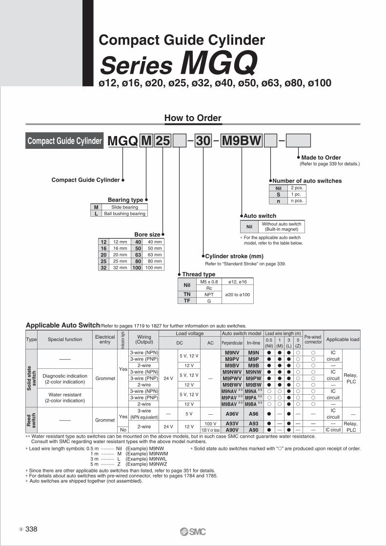
How to Order
MGQ M
Cylinder stroke (mm)Refer to “Standard Stroke” on page 339.
Slide bearingBall bushing bearing
Bearing typeML
12 mm16 mm20 mm25 mm32 mm
Bore size1216202532
40 mm50 mm63 mm80 mm
100 mm
40506380
100
M9BW
2 pcs.1 pc.n pcs.
Number of auto switchesNilSn
Auto switch
NilWithout auto switch
(Built-in magnet)
∗ For the applicable auto switch model, refer to the table below.
3025
M5 x 0.8Rc
NPTG
ø12, ø16
ø20 to ø100
Thread type
Nil
TNTF
Compact Guide Cylinder
Series MGQø12, ø16, ø20, ø25, ø32, ø40, ø50, ø63, ø80, ø100
Compact Guide Cylinder
Compact Guide Cylinder
Made to Order(Refer to page 339 for details.)
∗ Lead wire length symbols: 0.5 m ·········· Nil (Example) M9NW 1 m ·········· M (Example) M9NWM 3 m ·········· L (Example) M9NWL 5 m ·········· Z (Example) M9NWZ∗ Since there are other applicable auto switches than listed, refer to page 351 for details.∗ For details about auto switches with pre-wired connector, refer to pages 1784 and 1785.∗ Auto switches are shipped together (not assembled).
∗ Solid state auto switches marked with “” are produced upon receipt of order.
Applicable Auto Switch/Refer to pages 1719 to 1827 for further information on auto switches.
∗∗ Water resistant type auto switches can be mounted on the above models, but in such case SMC cannot guarantee water resistance. Consult with SMC regarding water resistant types with the above model numbers.
A96V
A93VA90V
M9NVM9PVM9BV
M9NWVM9PWVM9BWVM9NAV ∗∗M9PAV ∗∗M9BAV ∗∗
A96
A93A90
M9NM9PM9B
M9NWM9PWM9BWM9NA ∗∗M9PA ∗∗M9BA ∗∗
Type Special function
3-wire(NPN equivalent)
—
24 VGrommet
24 V
2-wire
3-wire (NPN)3-wire (PNP)
2-wire3-wire (NPN)3-wire (PNP)
2-wire3-wire (NPN)3-wire (PNP)
2-wire
Electricalentry
Load voltageWiring
(Output)Pre-wired connector Applicable load
DC AC
Auto switch model Lead wire length (m)
Perpendicular In-line0.5(Nil)
5(Z)
Grommet
—
100 V100 V or less
—
1(M)
ICcircuit
—IC circuit
ICcircuit
—IC
circuit—IC
circuit—
—
Relay, PLC
Relay, PLC
—
—
Diagnostic indication(2-color indication)
Water resistant(2-color indication)
5 V
12 V
5 V, 12 V
12 V
5 V, 12 V
12 V
5 V, 12 V
12 V
3(L)
So
lid s
tate
swit
chR
eed
swit
ch
Indic
ator
light
No
Yes
Yes
338

12, 16, 20, 25, 32, 40, 50, 63, 80, 100
Specifications
Double acting
Air
1.5 MPa
1.0 MPa
0.12 MPa
0.1 MPa
–10 to 60°C (No freezing)
50 to 500 mm/s
50 to 400 mm/s
Rubber bumper on both ends
Non-lube
mm
ø12, ø16
ø20 to ø100
ø12 to ø63
ø80, ø100
Standard Stroke Model Standard stroke (mm)
10, 20, 30, 40, 50, 75, 100
20, 30, 40, 50, 75, 100125, 150, 175, 200
25, 50, 75, 100, 125150, 175, 200
Intermediate stroke (mm)
MGQ 12, 16ML
ML
ML
MGQ 20, 25
MGQ32, 4050, 6380, 100
Theoretical Output (N)
Boresize (mm)
12
16
20
25
32
40
50
63
80
100
Rod size(mm)
Operatingdirection
6
8
10
12
16
16
20
20
25
30
0UT
IN
0UT
IN
0UT
IN
0UT
IN
0UT
IN
0UT
IN
0UT
IN
0UT
IN
0UT
IN
0UT
IN
Piston area(mm2)
113
85
201
151
314
236
491
378
804
603
1257
1056
1963
1649
3117
2803
5027
4536
7854
7147
0.2
23
17
40
30
63
47
98
76
161
121
251
211
393
330
623
561
1005
907
1571
1429
0.3
34
26
60
45
94
71
147
113
241
181
377
317
589
495
935
841
1508
1361
2356
2144
0.4
45
34
80
60
126
94
196
151
322
241
503
422
785
660
1247
1121
2011
1814
3142
2859
0.5
57
43
101
76
157
118
246
189
402
302
629
528
982
825
1559
1402
2514
2268
3927
3574
0.6
68
51
121
91
188
142
295
227
482
362
754
634
1178
990
1870
1682
3016
2722
4712
4288
0.7
79
60
141
106
220
165
344
265
563
422
880
739
1374
1154
2182
1962
3519
3175
5498
5003
0.8
90
68
161
121
251
189
393
302
643
482
1006
845
1570
1319
2494
2242
4022
3629
6283
5718
0.9
102
77
181
136
283
212
442
340
724
543
1131
950
1767
1484
2805
2523
4524
4082
7069
6432
1.0
113
85
201
151
314
236
491
378
804
603
1257
1056
1963
1649
3117
2803
5027
4536
7854
7147
Operating pressure (MPa)
Note) Theoretical output (N) = Pressure (MPa) x Piston area (mm2)
OUT(N) IN(N)
Slide bearing
MGQM
Ball bushing bearing
MGQL
+1.50
—XA�
—XB6
—XB9
—XB10
—XC22
—XC56
—XC79
—X168
—X367
—X399
—X563
Change of rod end shape
Heat resistant cylinder (–10 to 150°C)
Low speed cylinder (10 to 50 mm/s)
Intermediate stroke (Using exclusive body)
Fluororubber seals
With knock pin holes
Machining tapped hole, drilled hole, and pin hole additionally
Helical insert thread
Bottom mounting style
Long bushing type
With anti-strong magnetic field switch (D-P4DW)
Symbol Specifications
Made to Order Specifications(For details, refer to pages 1829 to 2021.)
Bearing type
Model
Air cylinder integrated with guide has achieved anti-lateral load and high non-rotating accuracy. Space-saving and compact designSuitable as stoppers or lifters in conveyor line2 types of guide rod bearing are available depending upon the application Slide bearing/Ball bushing bearing
Bore size (mm)
Action
Fluid
Proof pressure
Max. operating pressure
Min. operating pressure
Cushion
Lubrication
Stroke length tolerance
Ambient and fluid temperature
Piston speed
As for the intermediate strokes other than the standard strokes at left are manufactured by means of installing a spacer.ø12 to ø32 ······ Stroke available by the 1 stroke intervalø40 to ø100 ···· Stroke available by the 5 stroke interval(Example)1. For MGQM20-21 st, MGQM20-30 st is provided with a 5 mm + 4 mm ≤ 9 mm width spacer.2. For MGQM50-40 st, MGQM50-50 st is provided with a 10 mm width spacer.
339
Compact Guide Cylinder Series MGQ
MGJ
MGP
MGQ
MGG
MGC
MGF
MGZ
MGT
Individual-X�
D-�
-X�
P0255-P0352-E.qxd 08.11.17 2:19 PM Page 339

SpecificationsApplicable seriesBearing type
MGQMSlide bearing
MGQLBall bushing bearing
12, 16, 20, 25, 3240, 50, 63, 80, 100
Bore size(mm)
Copper and Fluorine-free Series (For CRT manufacturing process)
How to Order
Mass/Slide Bearing: MGQM12 to 100
12
16
20
25
32
40
50
63
80
100
Bore size(mm)
MGQM12
MGQM16
MGQM20
MGQM25
MGQM32
MGQM40
MGQM50
MGQM63
MGQM80
MGQM100
Model 10
0.23
0.34
—
—
—
—
—
—
—
—
20
0.27
0.39
0.54
0.83
—
—
—
—
—
—
25
—
—
—
—
1.51
1.65
2.54
3.01
5.66
8.96
30
0.31
0.45
0.61
0.93
—
—
—
—
—
—
Standard stroke (mm)
40
0.34
0.50
0.69
1.04
—
—
—
—
—
—
50
0.38
0.55
0.76
1.13
1.91
2.24
3.09
3.63
6.59
10.27
75
0.48
0.68
0.94
1.44
2.29
2.46
3.65
4.23
7.49
11.57
100
0.58
0.80
1.09
1.68
2.69
2.87
4.21
4.85
8.41
12.90
125
—
—
1.24
1.92
3.09
3.28
4.77
5.47
9.33
14.23
150
—
—
1.39
2.16
3.49
3.69
5.33
6.09
10.25
15.56
175
—
—
1.54
2.40
3.89
4.10
5.89
6.71
11.17
16.89
200
—
—
1.69
2.64
4.29
4.51
6.45
7.33
12.09
18.22
(kg)
Mass/Ball Bushing Bearing: MGQL12 to 100
12
16
20
25
32
40
50
63
80
100
Bore size(mm)
MGQL12
MGQL16
MGQL20
MGQL25
MGQL32
MGQL40
MGQL50
MGQL63
MGQL80
MGQL100
Model10
0.23
0.35
—
—
—
—
—
—
—
—
20
0.26
0.39
0.54
0.84
—
—
—
—
—
—
25
—
—
—
—
1.32
1.46
2.11
2.65
5.49
8.34
30
0.29
0.44
0.60
0.93
—
—
—
—
—
—
Standard stroke (mm)
40
0.35
0.52
0.70
1.08
—
—
—
—
—
—
50
0.38
0.57
0.75
1.17
1.67
1.82
2.59
3.19
6.38
9.53
75
0.46
0.70
0.90
1.37
2.09
2.27
3.19
3.85
7.95
11.78
100
0.53
0.82
1.04
1.58
2.45
2.63
3.68
4.39
8.79
12.96
125
—
—
1.18
1.79
2.81
2.99
4.17
4.93
9.63
14.14
150
—
—
1.32
2.00
3.17
3.35
4.66
5.47
10.47
15.32
175
—
—
1.46
2.21
3.53
3.71
5.15
6.01
11.31
16.50
200
—
—
1.60
2.42
3.89
4.07
5.64
6.55
12.15
17.68
(kg)
StrokeBore sizeMGQ
Copper and fluorine-free
Slide bearingBall bushing bearing
ML
20 M
Bearing type Port thread type
To prevent the influence of copper ions or halogen ions during CRT manufacturing processes, copper and fluorine materials are not used in the component parts.
340
Series MGQ
P0255-P0352-E.qxd 08.11.17 2:19 PM Page 340

A±0.2
B±0.
2
C±0.2
A±0.2
B±0
.22d
or
mor
e
(d=
Thr
ead
O.D
.)
Max. speed (mm/s)
Load
mas
s (k
g)
100
1000
100
10
0.1
0.01
ø100
ø80
ø63
ø32
ø25
ø16
ø12
ø20
ø50ø40
Max. speed (mm/s)
Load
mas
s (k
g)
100 500400300200
500400300200
1000
100
10
1
1
0.1
0.01
ø100
ø80
ø63
ø32
ø25
ø16
ø12
ø20
ø50ø40
øDBy-pass port dia.
øDBy-pass port dia.
Allowable Kinetic Energy
MGQ without a cushion (XB6, XC22)
MGQ with a rubber bumper
121620253240506380100
404252628090
100110140170
18222632383844445662
36384656——————
MGQM10121418222227273139
øD(mm)MGQL
8101215181822222833
M4 x 0.7M5 x 0.8M5 x 0.8M6 x 1
M8 x 1.25M8 x 1.25M10 x 1.5M10 x 1.5M12 x 1.75
M14 x 2
Bore size(mm)
A(mm)
B(mm)
C(mm)
Hexagon socket head cap screw
C dimension for a bore size of 32 to 100 is identical to the A dimension.
Mounting
Warning
Caution
Series MGQSpecific Product PrecautionsBe sure to read before handling. Refer to front matters 42 and 43 for Safety Instructionsand pages 3 to 11 for Actuator and Auto Switch Precautions.
1. Avoid placing your hands or fingers between the plate and the body.• Be very careful to prevent your hands or fingers from getting caught in
the gap between the cylinder body and the plate when air is applied.
1. Do not scratch or gouge the sliding portion of the piston rod and the guide rod.• Damaged seals, etc. will result in leakage or malfunction.
2. Do not dent or scratch the mounting surface of a body and a plate.• The flatness of the mounting surface may not be maintained, which would cause the sliding resistance to increase.
3. Make sure that the cylinder mounting surface has a flatness of 0.05 mm or less.• If the flatness of the workpieces and brackets mounted on the plate is not appropriate, sliding resistance may increase.
4. When mounting on the bottom of the cylinder, the guide rod protrudes from the bottom at the retraction stroke end. Therefore, drill holes for the hexagon socket bolts used for mounting purposes, and relief holes for the guide rods.Moreover, in applications where impact occurs from a stopper, etc., the mounting bolts should be inserted to a depth of 2 d or more.
Load mass and cylinder speed should be observed within therange given in the graph below.
341
MGJ
MGP
MGQ
MGG
MGC
MGF
MGZ
MGT
Individual-X�
D-�
-X�
P0255-P0352-E.qxd 08.11.17 2:19 PM Page 341

12
16
20
25
32
40
50
63
80
100
Bore size(mm)
MGQMMGQLMGQMMGQLMGQMMGQLMGQMMGQLMGQMMGQLMGQMMGQLMGQMMGQLMGQMMGQLMGQMMGQLMGQMMGQL
Bearing type1021273438————————————————
201822283051557071————————————
25————————
19688
19688
294137294137353235539470
301517252644476061————————————
Stroke (mm)401321223738785377————————————
501219193334694772
16759
16759
25588
25588
304157470313
759
15152857537759
137275137275215392215392255863412
1370
1008
13132349446551
108216108216176313176313206686343
1070
125————4230564287
15687
156138207138207168465278708
150————3726493677
13677
136123182123182151411252627
175————3323443269
12169
121111162111162137368230562
200————3021402963
10963
109101146101146126333211509
F(N)
12
16
20
25
32
40
50
63
80
100
MGQMMGQLMGQMMGQLMGQMMGQLMGQMMGQLMGQMMGQLMGQMMGQLMGQMMGQLMGQMMGQLMGQMMGQLMGQMMGQL
Bearing type100.290.480.510.73————————————————
200.240.390.430.580.911.261.531.96————————————
25————————
3.921.964.412.457.353.437.843.9211.769.3122.5421.56
300.210.310.350.480.781.061.311.69————————————
Stroke (mm)400.180.370.310.710.711.771.162.16————————————
500.160.330.270.640.631.581.032.002.940.983.431.475.882.206.372.459.805.8819.6013.72
750.130.270.230.531.041.221.681.652.455.882.946.374.9010.785.3911.767.8431.3616.6663.70
1000.100.230.190.440.881.011.421.413.464.412.455.394.418.334.909.316.8624.5014.7049.00
125————
0.770.691.241.181.723.121.943.513.435.183.775.695.8816.2811.8130.09
150————
0.680.601.091.011.532.721.723.063.064.553.375.015.2814.3910.6726.65
175————
0.600.530.980.901.372.421.542.722.774.053.044.464.7912.889.7423.89
200————
0.550.480.880.811.242.181.402.452.523.652.774.024.3911.668.9621.63
T (N.m)
Bore size(mm)
Bore size (mm)
121620253240506380
100
MGQM
±0.08°
±0.07°
±0.06°
±0.05°
±0.04°
MGQL
±0.10°
±0.09°
±0.08°
±0.06°
±0.05°
Non-rotating accuracy θ
Operating Conditions
Allowable Lateral Load (Ordinary load)
Allowable Rotational Torque of Plate
Non-rotating Accuracy of Plate
Torque: T (N·m)
For non-rotating accuracy θ without
load, use a value no more than the
values in the table as a guide.
342
Series MGQ
P0255-P0352-E.qxd 08.11.17 2:19 PM Page 342

0 10 20 30
10
20
30
40
50
60
70
80
90
Mas
s of
tran
sfer
red
obje
ct m
(kg
)M
ass
of tr
ansf
erre
d ob
ject
m (
kg)
ø25
ø20
ø16
ø12
Transfer speed υ (m/min)
010 20 30 40
100
200
300
400
500
600
700
800
900
1000
1500ø100
ø80
ø63
ø50
ø40
ø32
Transfer speed υ (m/min)
Operating Range when Used as Stopper
Bore Size ø12 to ø25/MGQM12 to 25 (Slide Bearing)
Bore Size ø32 to ø100/MGQM32 to 100 (Slide Bearing)
MGQM12 to 25 (Slide bearing)
MGQM32 to 100 (Slide bearing)
l ≅
50 m
m
l ≅
50 m
m
∗ When selecting a model with a longer l
dimension, be sure to choose a bore size which is sufficiently large.
Caution on handlingNote 1) When using as a stopper, select a model
with 30 stroke or less.Note 2) Model MGQL (Ball bushing bearing) cannot be used as a stopper.
∗ When selecting a model with a longer l dimension, be sure to choose a bore size which is sufficiently large.
Caution on handlingNote 1) When using as a stopper, select a model
with 50 stroke or less.Note 2) Model MGQL (Ball bushing bearing) cannot be used as a stopper.
l ≅
50 m
m
l ≅
50 m
m
343
Compact Guide Cylinder Series MGQ
MGJ
MGP
MGQ
MGG
MGC
MGF
MGZ
MGT
Individual-X�
D-�
-X�
P0255-P0352-E.qxd 08.11.17 2:19 PM Page 343

Operating Range when Used as Lifter
Bore size (mm) Theoretical output
40% or below
50% or below
60% or below
12, 16
20, 25
32 to 100
m
l
m
l
MGQM/Slide bearing
MGQM12 to 25-� MGQL12 to 25- (10, 20, 30 Stroke)
MGQM/Ball bushing bearing102030
MGQL12 to 25-Over 30 stroke
MGQM32 to 100 (Slide bearing) MGQL32 to 100- (25, 50 stroke)2550 MGQL32 to 100-Over 50 stroke
� Select the bore size so that the total load mass is bellow the theoretical output (see the table below).
Eccentric distance l (mm)
Eccentric distance l (mm)
Eccentric distance l (mm)
Eccentric distance l (mm)
Eccentric distance l (mm)
Eccentric distance l (mm)
Load
mas
s m
(kg
)
Load
mas
s m
(kg
)
Load
mas
s m
(kg
)
Load
mas
s m
(kg
)
Load
mas
s m
(kg
)
Load
mas
s m
(kg
)
344
Series MGQ
P0255-P0352-E.qxd 08.11.17 2:19 PM Page 344

345
MGJ
MGP
MGQ
MGG
MGC
MGF
MGZ
MGT
Individual-X�
D-�
-X�
P0255-P0352-E.qxd 08.11.17 2:19 PM Page 345

MGQM32 to 100
MGQM12 to 25
ø12, ø16
ø20, ø25 Over 50 stroke
Over 50 stroke
50 stroke or less
Construction/Series MGQM
Component PartsNo. Description Material Note
BodyPiston
Piston rod
Collar
Bushing
Head cover
Guide rodPlatePlate mounting boltGuide bolt
Aluminum alloyAluminum alloyStainless steelCarbon steel
Aluminum bearing alloyAluminum alloy casted
Babbitt
Aluminum alloy
Carbon steelCarbon steelCarbon steelCarbon steel
Hard anodizedChromated
Hard chrome platedNickel platedNickel platedNickel plated
ø12 to ø25ø32 to ø100ø12 to ø40ø50 to ø100ø50 to ø100ø12 to ø63ø80 to ø100
Hard chrome platedWhite anodized
Painted
ChromatedPainted
Description Material NoteRetaining ringRetaining ringBumper A Bumper B MagnetSlide BearingFeltHolderBall bushingPiston sealRod sealGasket AGasket B
Carbon tool steelCarbon tool steel
UrethaneUrethane
BabbittFelt
Resin
NBRNBRNBRNBR
Phosphate coatedPhosphate coated
Replacement Parts: Seal KitBore size
(mm)
1216202532
Kit no.
MGQ12-PSMGQ16-PSMGQ20-PSMGQ25-PSMGQ32-PS
Description Bore size(mm)
40506380100
Kit no.
MGQ40-PSMGQ50-PSMGQ63-PSMGQ80-PS
MGQ100-PS
Description
∗ Seal kit includes to . Order the seal kit, based on each bore size. ∗ Since the seal kit does not include a grease pack, order it separately. Grease pack part no.: GR-S-010 (10 g)
A set of , , and listed above20 21 22 23 A set of , , and listed above20 21 22 23
∗∗∗
∗
No.
20 23
346
Series MGQ
8 3 7 1
6
2
9
4
17 13 16 15
11
14
18
10
11
20
2222
21
9
3 16 1 7
14
6
5
4
8
11
10
18 17 2
20
1121
22 13
15
23
12
3
4
5
6
78910
11121314151617181920212223
P0255-P0352-E.qxd 08.11.17 2:19 PM Page 346

MGQL32 to 100
ø12, ø16 Over 30 stroke
30 stroke or less
ø50 or more
Construction/Series MGQL
MGQL12 to 25
ø20, ø25 Over 30 stroke
12 19
12 19
347
Compact Guide Cylinder Series MGQ
MGJ
MGP
MGQ
MGG
MGC
MGF
MGZ
MGT
Individual-X�
D-�
-X�
P0255-P0352-E.qxd 08.11.17 2:19 PM Page 347

2
U
W + StrokeZ
A + StrokeE
X
HV
L
KJG
PW
øD
Bø
DATR
TA TBSQ 8
B + StrokeC + Stroke
GBGA
4 x NN through2 x P
4 x YY depth YL
4 x MM depth ML
MGQM, MGQL Common Dimensions
MGQM (Slide bearing)/A, DB, E DimensionsBore size
(mm)
12162025
A50 st or less
47
47.5
39
43
0
0
Over 50 st
61.5
62
E50 st or less
0
0
Over 50 st
14.5
14.5
DB
8
10
12
16
MGQL (Ball bushing bearing)/A, DB, E DimensionsBore size
(mm)
12162025
A30 st or less
43
49
57
63.5
Over 30 st
55
65
74
79.5
E30 st or less
4
6
10
16
Over 30 st
16
22
27
32
DB
6
8
10
13
Bore size (mm)
12162025
Standard stroke(mm)
10, 20, 30, 40, 50, 75, 100
B
39
43
47
47.5
C
29
33
37
37.5
DA
6
8
10
12
G
29
33
36
42
GA
11
11
10.5
11.5
GB
7.5
8
8.5
9
H
58
64
74
88
J
16
18
19
21
K
13
15
17
21
L
18
22
26
32
MM
M4 x 0.7
M5 x 0.8
M5 x 0.8
M6 x 1.0
ML
10
13
13
15
PW
7
5
7
8
Q
14
16
18
26
R
48
52
60
70
NNP
TN TFNilM4 x 0.7
M5 x 0.8
M5 x 0.8
M6 x 1.0
M5 x 0.8
M5 x 0.8
Rc1/8
Rc1/8
—
—
NPT1/8
NPT1/8
—
—
G1/8
G1/820, 30, 40, 50, 75, 100125, 150, 175, 200
Bore size (mm)
12162025
S
22
25
30
38
T
56
62
72
86
TA
2
2.5
2
2
TB
5
5.5
4
2
U
36
38
46
56
V
40
42
52
62
W
5
7
10
10
X
50
54
64
76
YY
M4 x 0.7
M5 x 0.8
M5 x 0.8
M6 x 1.0
YL
7
8
8
9
Z
12
13
13
14
Bore Size ø12 to ø25: MGQM, MGQL
Note) For intermediate strokes other than standard strokes, refer to the Manufacture of Intermediate Stroke on page 339.� Bore size 12 and 16 are only for the M5 x 0.8 port.� For bore size 20 or more, Rc, NPT and G ports can be selected. (Refer to page 338.)
(mm)
(mm)(mm)
348
Series MGQ
P0255-P0352-E.qxd 08.11.17 2:19 PM Page 348

HV
X
PW
TR
øD
Bø
DA
GBGA2
F C + StrokeB + Stroke E
A + Stroke
W + StrokeZ
LKJ
GTBTA SQ
4 x NN through
2 x P
4 x YY depth YL
4 x MM depth ML
A
4
1.5
5.8
3.1 1.5
4
A5.8
3.1
a a
MGQL (Ball bushing bearing)/A, DB, E Dimensions
32 40 50 63 80100
A50 st or less
535460618489
Over 50 st 90 90102102143153
50 st or less5.50 4 0 9.55
Over 50 st42.536 46 41 68.569
EDB
161620202530
(mm)
Bore size (mm)
Bore size (mm)
32 40 50 63 80100
71.5 71.5
818193
105
A DB
202025252836
E
24 17.525 20 18.521
Grooves (Except ø12, ø16, ø20, ø25)
ModelMGQ�32MGQ�40MGQ�50MGQ�63MGQ�80MGQ�100
A 8 8 8 81010
Detailed figure of “a” section
MGQ�32 to 50 MGQ�63 to 100
Detailed figure of “b” section
MGQM, MGQL Common DimensionsBore size
(mm)
32 40 50 63 80100
Standard stroke(mm) B
47.554 56 61 74.584
C
37.544 44 49 56.566
DA
161620202530
F
8 810101616
G
51 51 59 72 92112
GA
12.514 14 16.519 23
GB
9 10 11 13.515.519
H
114124140150188224
J
25 25 29 35.545.555.5
K
26 26 30 36.546.556.5
L
383844445662
MM
M8 x 1.25M8 x 1.25M10 x 1.5M10 x 1.5M12 x 1.75M14 x 2
ML
202025253035
NN
M8 x 1.25M8 x 1.25M10 x 1.5M10 x 1.5M12 x 1.75M14 x 2
Rc1/8Rc1/8Rc1/4Rc1/4Rc3/8Rc3/8
NPT1/8NPT1/8NPT1/4NPT1/4NPT3/8NPT3/8
G1/8G1/8G1/4G1/4G3/8G3/8
P PW
152127333740
Q
303040506080
R
96106120130160190
S
48 48 56 69 88108
25, 50, 75, 100125,150175, 200
TN TFNil
Bore size (mm)
32 40 50 63 80100
T
112122138148185221
TA
2 2 2 2 2.52.5
TB
1 1 1 1 1.51.5
V
80 90100110140170
W
51010101515
X
100110124132166200
YY
M8 x 1.25M8 x 1.25M10 x 1.5M10 x 1.5M12 x 1.75M14 x 2
YL
11 11 12.515 18 21
Z
161717192125
Bore Size ø32 to ø100: MGQM, MGQL
Note) For intermediate strokes other than standard strokes, refer to the Manufacture of Intermediate Stroke on page 339.� Rc, NPT and G ports can be selected. (Refer to page 338.)
Use grooves section “a” and section “b” in the figure below of the
cylinder body for firmly fixing in the following case. (Applicable bolt
size is M3.)
• These grooves can be used for firmly fixing the tying bands of lead
wires of the auto switch, etc., and also terminal boards, etc., to the
main body of the cylinder.
• When the terminal block is fixed on a cylinder directly. bb
MGQM (Slide bearing)/A, DB, E Dimensions
349
Compact Guide Cylinder Series MGQ
(mm)
(mm)(mm)
MGJ
MGP
MGQ
MGG
MGC
MGF
MGZ
MGT
Individual-X�
D-�
-X�
P0255-P0352-E.qxd 08.11.17 2:19 PM Page 349

Minimum Stroke for Auto Switch
Auto Switch Proper Mounting Position (Detection at Sroke End)
(mm)
D-A9
D-A9VD-M9V
D-M9
D-M9W
D-M9AL
D-M9WVD-M9AVL
D-Z7D-Z80
D-Y59D-Y7P
D-Y69D-Y7PV
D-Y7WD-Y7WV
1 pc.
2 pcs.
1 pc.
2 pcs.
1 pc.
2 pcs.
1 pc.
2 pcs.
1 pc.
2 pcs.
1 pc.
2 pcs.
1 pc.
2 pcs.
1 pc.
2 pcs.
1 pc.
2 pcs.
5 Note 1)
10 Note 1)
5
10
5
10
10 Note 1)
10 Note 2)
10
10
5 Note 2)
10 Note 1) 10
10
5 Note 1)
5
5
5 Note 2)
10 Note 2)
5
10 Note 2)
5 Note 2)
5 Note 1) 5
(mm)
ø12 ø16 ø20 ø25 ø32 ø40 ø50 ø63 ø80 ø100Auto switch model No. of auto switches mounted
5 Note 2)
Note 1) Confirm that it is possible to secure the minimum bending radius of 10 mm of the auto switch lead wire before use.Note 2) Confirm that it is possible to securely set the auto switch(es) within the range of indicator green light ON range before use.
For in-line entry type, please also consider Note 1) shown above.
Auto Switch Proper Mounting PositionD-M9D-M9VD-M9WD-M9WVD-M9ALD-M9AVL
121620253240506380
100
A6
9
9.5
9.5
10.5
14.5
12.5
15
18
22.5
B8
9
12.5
13
12
14.5
16.5
19
23.5
28.5
D-A9D-A9V
A2
5
5.5
5.5
6.5
10.5
8.5
11
14
18.5
B4
5
8.5
9
8
10.5
12.5
15
19.5
24.5
D-Z7/Z80D-Y59/Y7PD-Y69/Y7PVD-Y7WD-Y7WV
A1
4
4.5
4.5
5.5
9.5
7.5
10
13
17.5
B3
4
7.5
8
7
9.5
11.5
14
18.5
23.5
Auto Switch Mounting HeightD-A9D-M9D-M9WD-M9ALD-Z7D-Z80D-Y59D-Y7PD-Y7W
121620253240506380
100
Hs16
18.5
19.5
21
24.5
24
28
34.5
44
52
D-A9V
Hs18.5
21
22.5
23.5
27
26
30
36.5
46.5
54
D-M9VD-M9WVD-M9AVL
Hs20.5
23
24.5
26
28.5
27.5
31.5
39.5
48.5
56
D-Y69D-Y7PVD-Y7WV
Hs17
19.5
20.5
22
25.5
25
29
35.5
45
52.5
B
≅Hs
A
Auto switch
Note) Adjust the auto switch after confirming the operating conditions in the actual setting.
Auto switchmodel
Auto switchmodel
Boresize(mm)
Boresize(mm)
350
Series MGQ
(mm)
(mm)

Auto Switch Mounting Bracket: Part No.
Bore size (mm)Auto switch model
BMG2-012D-A9�/A9�VD-M9�/M9�VD-M9�W/M9�WV
ø12 to ø100
Auto switch type Model FeaturesElectrical entry (Fetching direction)
D-Z73, Z76
D-Z80
D-Y69A, Y69B, Y7PV
D-Y7NWV, Y7PWV, Y7BWV
D-Y59A, Y59B, Y7P
D-Y7NW, Y7PW, Y7BW
—
Without indicator light
—
Diagnostic indication (2-color indication)
—
Diagnostic indication (2-color indication)
Grommet (In-line)
Grommet (Perpendicular)
Grommet (In-line)
Other than the applicable auto switches listed in “How to Order”, the following auto switches can be mounted.For detailed specifications, refer to pages 1719 to 1827.
Reed
Solid state
Auto switch modelBore size (mm)
7
4
5
129.5
5.5
6
169
5
6
209
5
6.5
259
5.5
8.5
329
5
8.5
409
5.5
9
5010.5
5.5
10
6310
6.5
10
8010.5
7
11.5
100
D-M9�/M9�VD-M9�W/M9�WV
D-A9�/A9�V
D-Z7�/Z80D-Y5��/Y6��/Y7��
Operating Range
BMG2-012
Since the operating range is provided as a guideline including hysteresis, it cannot be guaranteed (assuming approximately ±30% dispersion). It may vary substantially depending on an ambient environment.
D-A9�(V)/M9�(V)/M9�W(V)
∗ Normally closed (NC = b contact), solid state auto switch (D-F9G/F9H/Y7G/Y7H type) are also available. For details, refer to pages 1746 and 1748.
∗ For solid state auto switches, auto switches with a pre-wired connector are also available. Refer to pages 1784 and 1785 for details.
351
Compact Guide Cylinder Series MGQ
(mm)
MGJ
MGP
MGQ
MGG
MGC
MGF
MGZ
MGT
Individual-X�
D-�
-X�
P0255-P0352-E.qxd 08.11.17 2:19 PM Page 351