Embed Size (px)
Citation preview

Compact Linear Actuatorwith Ball Screw Drive
gbr__titel_standard__ina.fm Seite 1 Donnerstag, 8. April 2010 6:02 06

Foreword
In many applications (for example in the handling and automation sector), small loads must be moved reliably, quickly and accurately. Furthermore, there is often very little space available to accommodate handling systems.For these applications, we have developed our new compact linear actuators of series MKUVS32.
High load capacity, rigid,cost-effective, precise
The new compact linear actuators are standard, ready-to-fit compact actuators with high rigidity and load carrying capacity.They can support forces from all directions (apart from the direction of motion) and moments about all axes.They contain a precise guidance system, a rigid support rail and a precise drive unit with a high precision spindle.
Accessories The comprehensive standard range can be further optimised by means of a range of accessories precisely matched to various application requirements.
#tpi_181_FM8_en_gb.book Seite 1 Donnerstag, 8. April 2010 6:06 06

2 TPI 181 Schaeffler Group Industrial
#tpi_181_FM8_en_gb.book Seite 2 Donnerstag, 8. April 2010 6:06 06

Schaeffler Group Industrial TPI 181 3
Page
Compact linear actuatorwith ball screw drive
Product overview Compact linear actuator with ball screw drive ............................ 4
Features Applications ............................................................................. 6
Sealing..................................................................................... 6
Support rail .............................................................................. 7
Carriage.................................................................................... 7
Ball screw drive ........................................................................ 8
Available designs ..................................................................... 9
Design code.............................................................................. 10
Design andsafety guidelines
Maximum travel speed of carriage............................................. 11
Lubrication ............................................................................... 12
Location of support rail ............................................................. 14
Stroke length ............................................................................ 16
Accuracy Support rail .............................................................................. 18
Accessories Sensors .................................................................................... 19
Coupling housing cover............................................................. 20
Motor adapter plates ................................................................ 21
Couplings ................................................................................. 21
Clamping lugs........................................................................... 22
Ordering example,ordering designation
................................................................................................ 23
Dimension tables Compact linear actuators with ball screw driveCompact linear actuator with one carriage,without strip cover ............................................................... 24Compact linear actuator with one carriage,with strip cover .................................................................... 26Compact linear actuator with two carriages,without strip cover ............................................................... 28Compact linear actuator with two carriages,with strip cover .................................................................... 30
AccessoriesWorm couplings ................................................................... 32Cross couplings.................................................................... 33Motor adapter plates............................................................ 34
#tpi_181_FM8_en_gb.book Seite 3 Donnerstag, 8. April 2010 6:06 06

4 TPI 181 Schaeffler Group Industrial
Product overview Compact linear actuatorwith ball screw drive
Compact linear actuators MKUVS32
0001
4831
#tpi_181_FM8_en_gb.book Seite 4 Donnerstag, 8. April 2010 6:06 06

Schaeffler Group Industrial TPI 181 5
AccessoriesMotor adapter plate
APL
0001
48F5
CouplingCoupling housing cover
KUP ADH
0001
4A81
0001
48F6
Sensors INI
0001
48F7
Clamping lug SPPR
0001
48F8
#tpi_181_FM8_en_gb.book Seite 5 Donnerstag, 8. April 2010 6:06 06

6 TPI 181 Schaeffler Group Industrial
Compact linear actuatorwith ball screw drive
Features Compact linear actuators MKUVS32 comprise a support rail,one or two carriages guided in the support rail and a high precision ball screw drive.The carriage is guided in the support rail by means of two or four linear recirculating ball bearing units KUVS32.Due to their wide base and small height, the linear actuators ofthe SLIVER series allow high performance within compact dimensions.These linear actuators allow accelerations of up to 30 m/s2
and travel speeds of up to 1 m/s.The maximum stroke length is 1022 mm.
Applications The compact linear actuators can support forces from all directions and moments about all axes. They offer high load carrying capacity with high precision.They are highly suitable for applications in:■ assembly systems, for example in semiconductor production■ inspection and measurement systems■ medical equipment■ electronic component manufacture■ handling systems■ automatic welding equipment.
Sealing In order to protect the linear guidance system and drive spindle against contamination, linear actuators MKUVS32 can be supplied with strip covers made from alloy sheet steel (suffix ADA). In this design, the carriages are produced with a covering strip guide on both end faces. As a result, the stroke length is reduced.
#tpi_181_FM8_en_gb.book Seite 6 Donnerstag, 8. April 2010 6:06 06

Schaeffler Group Industrial TPI 181 7
Support rail The support rail is a composite rail, Figure 1. It comprises a profiled carrier rail made from anodised aluminium and a guideway for the linear recirculating ball bearing units. The integral slots allow simple mounting of end position and zero point sensors.The maximum length of the support rail is 1100 mm.
Carriage The carriage consists of an anodised aluminium saddle plate,the spindle nut and two or four linear recirculating ball bearing units KUVS32, Figure 2. It is driven by means of the ball screw drive.The linear guidance system and the spindle nut can be relubricated via two lubrication nipples on each of the longitudinal faces.The carriage has an integrated magnet for Hall sensors.
Figure 1Support rail 00
014A
46
Figure 2Carriage 00
014A
45
#tpi_181_FM8_en_gb.book Seite 7 Donnerstag, 8. April 2010 6:06 06

8 TPI 181 Schaeffler Group Industrial
Compact linear actuator with ball screw drive
Longer carriage or two carriages In order to support higher loads, linear actuators with a longer carriage are available (suffix 80).Linear actuators with carriages of the standard or long designare also available with two carriages arranged in series.The second carriage is not driven and is freely movable.
Location The carriage has threaded holes for fixing to the adjacent construction.
Ball screw drive The high precision ball screw drive is available with a pitch of 2 mm, 4 mm, 10 mm or 20 mm.The ball screw drive has a pitch accuracy of 52 �m/300 mm and a repeat accuracy of �20 �m for L2 � 550 mm.The maximum spindle speed is 3 000 min–1.
#tpi_181_FM8_en_gb.book Seite 8 Donnerstag, 8. April 2010 6:06 06

Schaeffler Group Industrial TPI 181 9
Available designs Available designs: see Figure 3 and Figure 4.
Figure 3Available designs,
actuators with one carriage
MKUVS32-KGT/2MKUVS32-KGT/4MKUVS32-KGT/10MKUVS32-KGT/20
MKUVS32-80-KGT/2MKUVS32-80-KGT/4MKUVS32-80-KGT/10MKUVS32-80-KGT/20
MKUVS32-KGT/2-ADAMKUVS32-KGT/4-ADAMKUVS32-KGT/10-ADAMKUVS32-KGT/20-ADA
MKUVS32-80-KGT/2-ADAMKUVS32-80-KGT/4-ADAMKUVS32-80-KGT/10-ADAMKUVS32-80-KGT/20-ADA
MKUVS32-OA
MKUVS32-80-OA
MKUVS32-OA-ADA
MKUVS32-80-OA-ADA
0001
4858
Figure 4Available designs,
actuators with two carriages
MKUVS32-KGT/2-W2MKUVS32-KGT/4-W2MKUVS32-KGT/10-W2MKUVS32-KGT/20-W2
MKUVS32-80-KGT/2-W2MKUVS32-80-KGT/4-W2MKUVS32-80-KGT/10-W2MKUVS32-80-KGT/20-W2
MKUVS32-KGT/2-ADA-W2MKUVS32-KGT/4-ADA-W2MKUVS32-KGT/10-ADA-W2MKUVS32-KGT/20-ADA-W2
MKUVS32-80-KGT/2-ADA-W2MKUVS32-80-KGT/4-ADA-W2MKUVS32-80-KGT/10-ADA-W2MKUVS32-80-KGT/20-ADA-W2
MKUVS32-OA-W2
MKUVS32-80-OA-W2
MKUVS32-OA-ADA-W2
MKUVS32-80-OA-ADA-W2
0001
4859
#tpi_181_FM8_en_gb.book Seite 9 Donnerstag, 8. April 2010 6:06 06

10 TPI 181 Schaeffler Group Industrial
Compact linear actuator with ball screw drive
Design code For the design codes of the available designs and for the designations of the available accessories see tables.
Available designs
Available accessories
Design code Description Design
80 Long carriage Variant
ADA Covering strip made from alloy sheet steel
KGT/2 Ball screw drive with spindle pitch 2 mm
KGT/4 Ball screw drive with spindle pitch 4 mm
KGT/10 Ball screw drive with spindle pitch 10 mm
KGT/20 Ball screw drive with spindle pitch 20 mm
OA Without drive, carriage freely movable
W2 Second, non-driven carriage
Designation Description Design
ADH Coupling housing cover Standard
APL Motor adapter plate
INI Sensors
KUP Coupling
SPPR Clamping lug
#tpi_181_FM8_en_gb.book Seite 10 Donnerstag, 8. April 2010 6:06 06
Schaeffler Group Industrial TPI 181 11
Design andsafety guidelines
Maximum travel speedof carriage
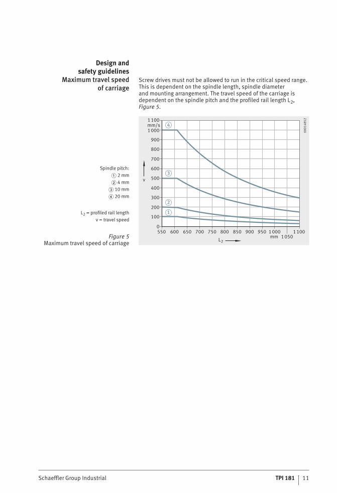
Screw drives must not be allowed to run in the critical speed range. This is dependent on the spindle length, spindle diameterand mounting arrangement. The travel speed of the carriage is dependent on the spindle pitch and the profiled rail length L2, Figure 5.
Spindle pitch:� 2 mm� 4 mm
� 10 mm� 20 mm
L2 = profiled rail lengthv = travel speed
Figure 5Maximum travel speed of carriage
1100
1000
900
800
700
600
500
400
300
200
100
0
mm/s
v
550 600 650 700 750 800 850 900 950 10001050
1100
L2
4
3
2
1
mm
0001
4852
#tpi_181_FM8_en_gb.book Seite 11 Donnerstag, 8. April 2010 6:06 06

12 TPI 181 Schaeffler Group Industrial
Compact linear actuator with ball screw drive
Lubrication The guidance systems and the ball screw drive in the compact linear actuators are supplied with an initial grease filling of a high quality lithium complex soap grease KP2P–35 to DIN 51 825 and must be relubricated during operation.
Lubrication of the guidance systems The guidance systems and the ball screw drive (the contact zones between the rolling elements and raceways) must be lubricated.The relubrication intervals are essentially dependent on the carriage travel speed, the load, the operating temperature, the stroke length and the environmental conditions. The cleaner the environment,the lower the lubricant consumption.The carriage must be moved during the lubrication process.The carriage must be moved slowly during relubricationof the spindle nut (Figure 6 � or �).Relubrication should be carried out using a lithium or lithium complex soap grease with a mineral oil or poly-alpha-olefin base.If different greases are used, their miscibility and compatibilitymust be checked first.The viscosity of the base oil should be in the range ISO-VG 68to ISO-VG 100. The consistency corresponds to NLGI class 2.The grease must have particular anti-wear characteristics at loads of C/P � 8. This is indicated by the letter P in the DIN designation,for example: DIN 51 825–KP2P–35.Relubrication should be carried out wherever possible with several partial quantities at various times instead of the complete quantity at the time of the relubrication interval.Relubrication is carried out via three lubrication nipples onthe longitudinal faces of the carriage.Lubricant must be supplied to the guidance system from the leftand right (lubrication points � and �) and can be supplied tothe ball screw drive from the left or right (lubrication point � or �).
For relubrication, a conical or needlepoint grease nozzle must be used to press the lubricant into the lubrication nipple.
�, � Lubrication points for the linearrecirculating ball bearing units
�, � Lubrication points for the spindle nut
Figure 6Lubrication points
13
24
0001
4863
#tpi_181_FM8_en_gb.book Seite 12 Donnerstag, 8. April 2010 6:06 06

Schaeffler Group Industrial TPI 181 13
The threads of the lubrication nipples can also be used for connection to a central lubrication system.The grease gun, lubrication nipple, vicinity of the lubrication nipple and grease must be clean.Lubrication should always be carried out with the linear actuator warm from operation.Move the carriage during lubrication.Move the carriage slowly during relubrication of the spindle nut(� or �).
Calculation of lubrication intervals Since it is not possible to calculate all the influencing factors,the time at which relubrication must be carried out and the quantity of lubricant which must be used can only be precisely determined under actual operating conditions.If no precise data are available, the values for many applications can be taken from the table.Relubrication must be carried out at the latest when fretting corrosion first occurs, which is visible as a reddish discolourationof the raceways. The subsequent lubrication intervals must be shortened.An approximation formula can be used, however, to determinea guide value for many applications.Detailed information on calculating the grease operating life is given in the Catalogue PF 1, Monorail Guidance Systems.
Relubrication quantityper lubrication point
Any lubrication method involves loss of lubricant.The used lubricant must be collected and disposed of by methods that help to protect the environment.The handling and use of lubricants is governed by national regulations for environmental protection and health and safetyat work as well as information from the lubricant manufacturers. These specifications must be observed.
Design Lubrication points Relubrication quantity
�g
Standard � 0,5
� 0,5
� or � 1 per 100 mm travel distance
Long carriage(suffix 80)
� 1
� 1
� or � 1 per 100 mm travel distance
#tpi_181_FM8_en_gb.book Seite 13 Donnerstag, 8. April 2010 6:06 06

14 TPI 181 Schaeffler Group Industrial
Compact linear actuator with ball screw drive
Location of the support railLocation using clamping lugs Clamping lugs are suitable for location of the linear actuator on
the adjacent construction. If the actuator is fully supported,clamping lugs must be arranged at both ends of the support railand then on both sides at intervals of no more than 300 mm, Figure 7.For heavy load conditions are present, the quantity of clamping lugs must be increased!
Location using screws For location of the linear actuator on the adjacent construction,the underside of the support rail has threaded holes at intervalsof 40 mm, Figure 8.The end distance T2 is dependent on the profiled rail length and the number of holes. It is a minimum of 15 mm and a maximum of 35 mm.
Figure 7Location using clamping lugs
�300
�300
114100
0001
4851
� Threaded hole M4�15
L2 = profiled rail lengthT2 = end distance
Figure 8Threaded holes on the underside
of the support rail
T2
2L
T40
68
1 2
0001
4850
#tpi_181_FM8_en_gb.book Seite 14 Donnerstag, 8. April 2010 6:06 06

Schaeffler Group Industrial TPI 181 15
Final spacing value and numberof threaded holes
The table gives the end distance T2 for fixed profiled rail lengths, intermediate lengths can be calculated.The end distance T2 is calculated using the following formula:
T2 mmEnd distanceL2 mmProfiled rail lengthn –Number of threaded holes
Profiled rail length Number of threaded holes(per side)
End distance
L2 n T2
150 3 35
200 5 20
250 6 25
300 7 30
350 7 35
400 10 20
450 11 25
500 12 30
550 13 35
600 15 20
650 16 25
700 17 30
750 18 35
800 20 20
850 21 25
900 22 30
950 23 35
1 000 25 20
1 050 26 25
1 100 27 30
TL n
22 40 1
2=
− ⋅ −( )
#tpi_181_FM8_en_gb.book Seite 15 Donnerstag, 8. April 2010 6:06 06
16 TPI 181 Schaeffler Group Industrial
Compact linear actuator with ball screw drive
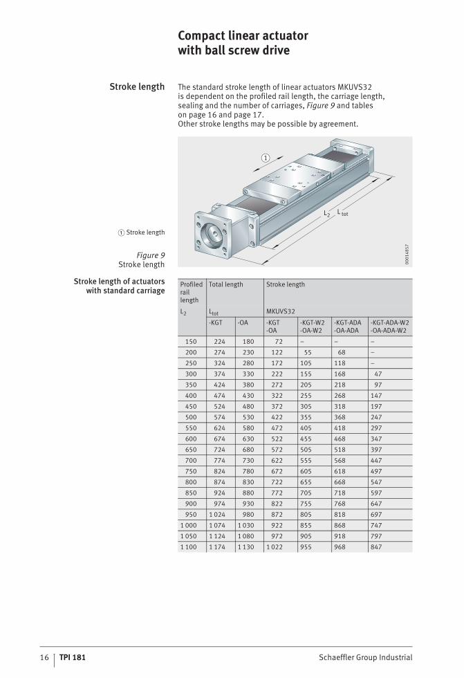
Stroke length The standard stroke length of linear actuators MKUVS32is dependent on the profiled rail length, the carriage length,sealing and the number of carriages, Figure 9 and tables on page 16 and page 17.Other stroke lengths may be possible by agreement.
Stroke length of actuatorswith standard carriage
� Stroke length
Figure 9Stroke length
L L
1
2 tot
0001
4857
Profiled rail length
Total length Stroke length
L2 Ltot MKUVS32
-KGT -OA -KGT-OA
-KGT-W2-OA-W2
-KGT-ADA-OA-ADA
-KGT-ADA-W2-OA-ADA-W2
150 224 180 72 – – –
200 274 230 122 55 68 –
250 324 280 172 105 118 –
300 374 330 222 155 168 47
350 424 380 272 205 218 97
400 474 430 322 255 268 147
450 524 480 372 305 318 197
500 574 530 422 355 368 247
550 624 580 472 405 418 297
600 674 630 522 455 468 347
650 724 680 572 505 518 397
700 774 730 622 555 568 447
750 824 780 672 605 618 497
800 874 830 722 655 668 547
850 924 880 772 705 718 597
900 974 930 822 755 768 647
950 1 024 980 872 805 818 697
1 000 1 074 1 030 922 855 868 747
1 050 1 124 1 080 972 905 918 797
1 100 1 174 1 130 1 022 955 968 847
#tpi_181_FM8_en_gb.book Seite 16 Donnerstag, 8. April 2010 6:06 06

Schaeffler Group Industrial TPI 181 17
Stroke length of actuatorswith long carriage
Profiled rail length
Total length Stroke length
L2 Ltot MKUVS32-80
-KGT -OA -KGT-OA
-KGT-W2-OA-W2
-KGT-ADA-OA-ADA
-KGT-ADA-W2-OA-ADA-W2
200 274 230 72 – – –
250 324 280 122 – 68 –
300 374 330 172 55 118 –
350 424 380 222 105 168 –
400 474 430 272 155 218 47
450 524 480 322 205 268 97
500 574 530 372 255 318 147
550 624 580 422 305 368 197
600 674 630 472 355 418 247
650 724 680 522 405 468 297
700 774 730 572 455 518 347
750 824 780 622 505 568 397
800 874 830 672 555 618 447
850 924 880 722 605 668 497
900 974 930 772 655 718 547
950 1 024 980 822 705 768 597
1 000 1 074 1 030 872 755 818 647
1 050 1 124 1 080 922 805 868 697
1 100 1 174 1 130 972 855 918 747
#tpi_181_FM8_en_gb.book Seite 17 Donnerstag, 8. April 2010 6:06 06

18 TPI 181 Schaeffler Group Industrial
Compact linear actuator with ball screw drive
AccuracySupport rail The support rail of the compact linear actuator is precision
straightened. The tolerances are maximum values and are not valid for unmounted support rails. When mounted, the shape of the extruded profile adapts to the mounting surface. The methodfor determining the straightness of the support rail is shown in Figure 10.
Straightness toleranceof support rail
Length toleranceof support rail
Length of support rail MKUVS32
L2mm
t2mm
t3mm
Torsionmm
L2 � 1 100 0,4 0,3 0,8
Length of support rail MKUVS32
L2mm
Tolerancemm
L2 � 1 100 �0,5
Figure 10Straightness tolerance
of support rail
t t23
0001
4854
#tpi_181_FM8_en_gb.book Seite 18 Donnerstag, 8. April 2010 6:06 06

Schaeffler Group Industrial TPI 181 19
AccessoriesSensors For linear actuators MKUVS32, end position and
zero point sensors are available in various configurations,see table Designation of sensors, page 20.Typical end position sensors are designed as openers,typical zero point sensors as closers, Figure 11,and connection scheme, Figure 13, page 20.The sensors contain Hall effect elements that detect a magnet integrated in the side of the drive carriage.For ease of mounting, the sensors are supplied with a 300 mm long cable and an M8 3 pin industry standard connector.In addition, a matching 5 metre long cable is available with a plug at one end and bare cable ends at the other.
The individual sensors are located flush in a lateral slot in the support rail, Figure 12. The sensors can be arranged at any point over the entire length of the linear actuator and are fixed in place by means of a set screw in the sensor head.
� End position sensor� Zero point sensor
� M8 3 pin plug� Connection cable
Figure 11End position and zero point sensors
1
1
4
2
3
0001
4866
� LED� Fixing screw
� Widened slot for sensor mounting,on drive side only
Figure 12Location of sensors
12
3
38
0001
4865
#tpi_181_FM8_en_gb.book Seite 19 Donnerstag, 8. April 2010 6:06 06

20 TPI 181 Schaeffler Group Industrial
Compact linear actuator with ball screw drive
Designation of sensors
Designation of the connection cable
Coupling housing cover The openings above and below the coupling housing can be closed off using a cover, Figure 14.The cover and mounting material are available as a set.
Designationof coupling housing covers
� PNP logic� NPN logic
� BRN� BLK� BLU
Figure 13Connection scheme
3
1 2
+
_
+
_
4
5
3
4
5
0001
48F4
Designation Logic Design Voltage Switched currentmax.
INI-CS-50NNC-QD NPN logic Closer 10–30 V DC 100 mA
INI-CS-40TN-QD NPN logic Opener 10–30 V DC 100 mA
INI-CS-50PNC-QD PNP logic Closer 10–30 V DC 100 mA
INI-CS-40TP-QD PNP logic Opener 10–30 V DC 100 mA
Designation Description
NI-M83R-PUR-5M Connection cable for sensors INI-CS-..-QDLength 5 mm
� Upper coupling housing cover� Lower coupling housing cover
Figure 14Coupling housing cover
1
2
0001
485A
Designation Description
ADH.MKUVS32-KGT-0400 upper and lower coupling housing coverswith fixing material
#tpi_181_FM8_en_gb.book Seite 20 Donnerstag, 8. April 2010 6:06 06

Schaeffler Group Industrial TPI 181 21
Motor adapter plates In order to mount a motor on the linear actuator MKUVS32,an adapter plate is required; for available designs seedimension table page 34.Other adapter plates are available by agreement.
Couplings For linear actuators MKUVS32, worm couplings or cross couplings are available, see dimension tables page 32 and page 33,as well as Figure 15 and Figure 16. They are clamped to the drive shaft and motor shaft to transmit the drive torque.
Figure 15Worm coupling KUP-H 00
014A
82
Figure 16Cross coupling KUP-S 00
014A
84
#tpi_181_FM8_en_gb.book Seite 21 Donnerstag, 8. April 2010 6:06 06

22 TPI 181 Schaeffler Group Industrial
Compact linear actuator with ball screw drive
Clamping lugs Clamping lugs are required for location of the support rail on the adjacent construction, Figure 17. They are made from anodised aluminium.
Design of clamping lug
Figure 17Dimensions of clamping lug
12
205
8
7
5,5
7
1120
�
�
0001
4A44
Designation Description
SPPR12�20 Clamping lug
#tpi_181_FM8_en_gb.book Seite 22 Donnerstag, 8. April 2010 6:06 06

Schaeffler Group Industrial TPI 181 23
Ordering example,ordering designation
Ordering designation MKUVS32-80-KGT/2-ADA-W2/550-197, Figure 18
Compact linear actuator with ball screw drive MKUVSSize 32Carriage length 80Drive by ball screw drive KGTSpindle pitch 2 mmStrip cover ADA2 carriages (non-driven) W2Guideway length 550 mmTotal stroke length 197 mm
Figure 18Ordering example,
ordering designation
550
MKUVS32-80-KGT/2-ADA-W2/550-197
197
0001
4A47
#tpi_181_FM8_en_gb.book Seite 23 Donnerstag, 8. April 2010 6:06 06

24 TPI 181 Schaeffler Group Industrial
Compact linear actuatorswith ball screw driveLinear actuator with one carriagewithout strip cover
MKUVS32-KGT
LL
10,515
L
59
36,5
12
�5
L
Ltot1)
2)2
3
1
0001
4A40
1)
2)
3) The values are single loads and apply if the underside of the actuator is fully supported.If combined loads are present, please contact us for rating life calculation.
4)
5)
6) Dynamic and axial loads for the spindle bearing arrangement.Applications must not exceed an axial load of 510 N.
Dimension table · Dimensions in mm
Designation Spindle Mass Dimensions
d0�p4) mtot mLaw5) L L1 L3
�kg �kg
MKUVS32-KGT/2 10X2
(L2 · 0,0055) � 0,67 0,330 57 61
MKUVS32-KGT/4 10X4
MKUVS32-KGT/10 10X10
MKUVS32-KGT/20 10X20
MKUVS32-OA – (L2 · 0,0049) � 0,58 0,21
MKUVS32-80-KGT/2 10X2
(L2 · 0,0055) � 0,94 0,5880 107 111
MKUVS32-80-KGT/4 10X4
MKUVS32-80-KGT/10 10X10
MKUVS32-80-KGT/20 10X20
MKUVS32-80-OA – (L2 · 0,0049) � 0,85 0,49
Total stroke length = effective stroke length + 2 · S (mm)S = The allowance S designates a safety range suitable for the particular application
and should be at least two thread turns.L2 = Total stroke length + L1 + 21Ltot = Total stroke length + L1 + 95 for linear actuator with ball screw drive (suffix KGT)Ltot = Total stroke length + L1 + 51 for linear actuator without drive (suffix OA)L2 max = 1100 mm for spindle pitch 10 mm and 20 mmL2 max = 550 mm for spindle pitch 2 mm and 4 mm.
d0�p = nominal diameter�spindle pitch.mLaw = Mass of carriage.
Load directions (schematic)
X
Mz
Z
Y
My
Mx
0001
4834
#tpi_181_FM8_en_gb.book Seite 24 Donnerstag, 8. April 2010 6:06 06

Schaeffler Group Industrial TPI 181 25
MKUVS32-OA
L
L
10,515
L
LL 1)
tot
2
3
1
0001
4A42
Carriage�, � 7)
LL
6459
�0,
02
15L
20�0,02
12
LL
6459
�0,
02
15 50L
20�0,02
21
1
3
1
3
0001
486c
7)
Basic load ratings Static moment ratingof linear guidance system3)
Geometrical momentsof inertiaof support rail
Carriage guidancesystem3)
Spindle nut Spindle bearing arrangement6)
M0x M0y M0z Iy Iz
Cy, Cz C0y, C0z Cx C0x Cx C0x
N N N N N N Nm Nm Nm cm4 cm4
5 700 10 600
2 133 5 300
1 810 1 520167 46 46 83 14
2 370 5 200
2 607 5 900
1 659 4 000
– – – –
9 300 21 200
2 133 5 300
1 810 1 520334 342 342 83 14
2 370 5 200
2 607 5 900
1 659 4 000
– – – –
� Threaded hole M5�10� Hole �3H7�4� Hole �42H7�3,5� Threaded hole M4�12
MKUVS32 MKUVS32, drive side�, � 7)
7678
30,8
5
440
°37,5
380
48
0001
4864
15,7529,5
28
46 43
0001
4867
#tpi_181_FM8_en_gb.book Seite 25 Donnerstag, 8. April 2010 6:06 06

26 TPI 181 Schaeffler Group Industrial
Compact linear actuatorswith ball screw driveLinear actuator with one carriagewith strip cover
MKUVS32-KGT..-ADA
LL
10,515
L
59
36,5
12
�5
L
Ltot1)
2)2
3
1
0001
4832
1)
2)
3) The values are single loads and apply if the underside of the actuator is fully supported.If combined loads are present, please contact us for rating life calculation.
4)
5)
6) Dynamic and axial loads for the spindle bearing arrangement.Applications must not exceed an axial load of 510 N.
Dimension table · Dimensions in mm
Designation Spindle Mass Dimensions
d0�p4) mtot mLaw5) L L1 L3
�kg �kg
MKUVS32-KGT/2-ADA 10X2
(L2 · 0,0056) � 0,72 0,3530 111 117
MKUVS32-KGT/4-ADA 10X4
MKUVS32-KGT/10-ADA 10X10
MKUVS32-KGT/20-ADA 10X20
MKUVS32-OA-ADA – (L2 · 0,0050) � 0,63 0,26
MKUVS32-80-KGT/2-ADA 10X2
(L2 · 0,0056) � 0,99 0,6280 161 167
MKUVS32-80-KGT/4-ADA 10X4
MKUVS32-80-KGT/10-ADA 10X10
MKUVS32-80-KGT/20-ADA 10X20
MKUVS32-80-OA-ADA – (L2 · 0,0050) � 0,90 0,53
Total stroke length = effective stroke length + 2 · S (mm)S = The allowance S designates a safety range suitable for the particular application
and should be at least two thread turns.L2 = Total stroke length + L1 + 21Ltot = Total stroke length + L1 + 95 for linear actuator with ball screw drive (suffix KGT)Ltot = Total stroke length + L1 + 51 for linear actuator without drive (suffix OA)L2 max = 1100 mm for spindle pitch 10 mm and 20 mmL2 max = 550 mm for spindle pitch 2 mm and 4 mm.
d0�p = nominal diameter�spindle pitch.mLaw = Mass of carriage.
Load directions (schematic)
X
Mz
Z
Y
My
Mx
0001
4834
#tpi_181_FM8_en_gb.book Seite 26 Donnerstag, 8. April 2010 6:06 06

Schaeffler Group Industrial TPI 181 27
MKUVS32-OA..-ADA
L
L
10,515
L
LL 1)
tot
2
3
1
0001
485f
Carriage�, � 7)
LL
5964 �
0,02
20
50L
15
�0,02
12
5964 �
0,02
LL
20�0,02
15L 1
2
1
3
1
3
0001
486D
7)
Basic load ratings Static moment ratingof linear guidance system3)
Geometrical momentsof inertiaof support rail
Carriage guidancesystem3)
Spindle nut Spindle bearing arrangement6)
M0x M0y M0z Iy Iz
Cy, Cz C0y, C0z Cx C0x Cx C0x
N N N N N N Nm Nm Nm cm4 cm4
5 700 10 600
2 133 5 300
1 810 1 520167 46 46 83 14
2 370 5 200
2 607 5 900
1 659 4 000
– – – –
9 300 21 200
2 133 5 300
1 810 1 520334 342 342 83 14
2 370 5 200
2 607 5 900
1 659 4 000
– – – –
� Threaded hole M5�10� Hole �3H7�4� Hole �42H7�3,5� Threaded hole M4�12
MKUVS32 MKUVS32, drive side�, � 7)
7678
30,8
5
440
°37,5
380
48
0001
4864
15,7529,5
28
46 43
0001
4867
#tpi_181_FM8_en_gb.book Seite 27 Donnerstag, 8. April 2010 6:06 06

28 TPI 181 Schaeffler Group Industrial
Compact linear actuatorswith ball screw driveLinear actuator with two carriageswithout strip cover
MKUVS32-KGT-W2
LL
10,515
LLL
L
5936,5
12
�5
L
L 1)
2)
1
3
2
tot
1
3
0001
4A41
1)
2)
Dimension table · Dimensions in mm
Designation Spindle Mass Dimensions
d0�p4) mtot mLaw5) L L1 L3
Driven Non-driven
�kg �kg �kg
MKUVS32-KGT/2-W2 10X2
(L2 · 0,0055) � 0,89 0,30,21 30 57 61
MKUVS32-KGT/4-W2 10X4
MKUVS32-KGT/10-W2 10X10
MKUVS32-KGT/20-W2 10X20
MKUVS32-OA-ADA – (L2 · 0,0049) � 0,8 –
MKUVS32-80-KGT/2-W2 10X2
(L2 · 0,0055) � 1,43 0,580,49 80 107 111
MKUVS32-80-KGT/4-W2 10X4
MKUVS32-80-KGT/10-W2 10X10
MKUVS32-80-KGT/20-W2 10X20
MKUVS32-80-OA-W2 – (L2 · 0,0049) � 1,34 –
Total stroke length = effective stroke length + 2 · S (mm)S = The allowance S designates a safety range suitable for the particular application
and should be at least two thread turns.L2 = Total stroke length + 2�L1 + L4 + 21Ltot = Total stroke length + 2�L1 + L4 + 95 for linear actuator with ball screw drive (suffix KGT)Ltot = Total stroke length + 2�L1 + L4 + 51 for linear actuator without drive (suffix OA)L4 = Distance between carriage centres.
In linear actuators with ball screw drive, one carriage is driven(connected to the spindle), while the other is freely movable.In linear actuators without drive, both carriages are freely movable.
L4 min = L1 + 10L2 max = 1100 mm for spindle pitch 10 mm and 20 mmL2 max = 550 mm for spindle pitch 2 mm and 4 mm.
Load directions (schematic) MKUVS32-KGT-W2
X
Mz
Z
Y
My
Mx
0001
4834
L4
0001
4862
#tpi_181_FM8_en_gb.book Seite 28 Donnerstag, 8. April 2010 6:06 06

Schaeffler Group Industrial TPI 181 29
MKUVS32-OA-ADA
LL
10,515
L
LL
LL
L
1)tot
2
3
1
3
1
0001
4A43
Carriage�, � 8)
LL
6459
�0,
02
15L
20�0,02
12
LL
6459
�0,
02
15 50L
20�0,02
21
1
3
1
3
0001
486c
3) The values are single loads and apply if the underside of the actuator is fully supported.If combined loads are present, please contact us for rating life calculation.
4)
5)
6) Dynamic and axial loads for the spindle bearing arrangement.Applications must not exceed an axial load of 510 N.
7) Attention! M0y and M0z are dependent on L4.For calculation of applications with moment loads, please contact us.
8)
Basic load ratings Static moment ratingof linear guidance system3)
Geometrical momentsof inertiaof support rail
Carriage guidancesystem3)
Spindle nut Spindle bearing arrangement6)
M0x M0y7) M0z
7) Iy Iz
Cy, Cz C0y, C0z Cx C0x Cx C0x
N N N N N N Nm Nm Nm cm4 cm4
9 300 21 200
2 133 5 300
1 810 1 520334 – – 83 14
2 370 5 200
2 607 5 900
1 659 4 000
– – – –
15 000 42 400
2 133 5 300
1 810 1 520669 – – 83 14
2 370 5 200
2 607 5 900
1 659 4 000
– – – –
d0�p = nominal diameter�spindle pitch.mLaw = Mass of carriage.
� Threaded hole M5�10� Hole �3H7�4� Hole �42H7�3,5� Threaded hole M4�12
MKUVS32 MKUVS32, drive side�, � 8)
7678
30,8
5
440
°37,5
380
48
0001
4864
15,7529,5
28
46 43
0001
4867
#tpi_181_FM8_en_gb.book Seite 29 Donnerstag, 8. April 2010 6:06 06

30 TPI 181 Schaeffler Group Industrial
Compact linear actuatorswith ball screw driveLinear actuator with two carriageswith strip cover
MKUVS32-KGT..-ADA-W2
LL
10,515
LLL
L
5936,5
12
�5
LL 1)
1
3
2
tot
1
3
2)
0001
4833
1)
2)
Dimension table · Dimensions in mm
Designation Spindle Mass Dimensions
d0�p4) mtot mLaw5) L L1 L3
Driven Non-driven
�kg �kg �kg
MKUVS32-KGT/2-ADA-W2 10X2
(L2 · 0,0056) � 0,98 0,350,26 30 111 117
MKUVS32-KGT/4-ADA-W2 10X4
MKUVS32-KGT/10-ADA-W2 10X10
MKUVS32-KGT/20-ADA-W2 10X20
MKUVS32-OA-ADA-W2 – (L2 · 0,0050) � 0,89 –
MKUVS32-80-KGT/2-ADA-W2 10X2
(L2 · 0,0056) � 1,52 0,620,53 80 161 167
MKUVS32-80-KGT/4-ADA-W2 10X4
MKUVS32-80-KGT/10-ADA-W2 10X10
MKUVS32-80-KGT/20-ADA-W2 10X20
MKUVS32-80-OA-ADA-W2 – (L2 · 0,0050) � 1,43 –
Total stroke length = effective stroke length + 2 · S (mm)S = The allowance S designates a safety range suitable for the particular application
and should be at least two thread turns.L2 = Total stroke length + 2�L1 + L4 + 21Ltot = Total stroke length + 2�L1 + L4 + 95 for linear actuator with ball screw drive (suffix KGT)Ltot = Total stroke length + 2�L1 + L4 + 51 for linear actuator without drive (suffix OA)L4 = Distance between carriage centres.
In linear actuators with ball screw drive, one carriage is driven(connected to the spindle), while the other is freely movable.In linear actuators without drive, both carriages are freely movable.
L4 min = L1 + 10L2 max = 1100 mm for spindle pitch 10 mm and 20 mmL2 max = 550 mm for spindle pitch 2 mm and 4 mm.
Load directions (schematic) MKUVS32-KGT..-ADA-W2
X
Mz
Z
Y
M y
Mx
0001
4834
L4
0001
4862
#tpi_181_FM8_en_gb.book Seite 30 Donnerstag, 8. April 2010 6:06 06

Schaeffler Group Industrial TPI 181 31
MKUVS32-OA..-W2
LL
10,515
L
LL
LL
L
1)tot
2
3
1
3
1
0001
4861
Carriage�, � 8)
LL
5964 �
0,02
20
50L
15
�0,02
12
5964 �
0,02
LL
20�0,02
15L 1
2
1
3
1
3
0001
486D
3) The values are single loads and apply if the underside of the actuator is fully supported.If combined loads are present, please contact us for rating life calculation.
4)
5)
6) Dynamic and axial loads for the spindle bearing arrangement.Applications must not exceed an axial load of 510 N.
7) Attention! M0y and M0z are dependent on L4.For calculation of applications with moment loads, please contact us.
8)
Basic load ratings Static moment ratingof linear guidance system3)
Geometrical momentsof inertiaof support rail
Carriage guidancesystem3)
Spindle nut Spindle bearing arrangement6)
M0x M0y7) M0z
7) Iy Iz
Cy, Cz C0y, C0z Cx C0x Cx C0x
N N N N N N Nm Nm Nm cm4 cm4
9 300 21 200
2 133 5 300
1 810 1 520334 – – 83 14
2 370 5 200
2 607 5 900
1 659 4 000
– – – –
15 000 42 400
2 133 5 300
1 810 1 520669 – – 83 14
2 370 5 200
2 607 5 900
1 659 4 000
– – – –
d0�p = nominal diameter�spindle pitch.mLaw = Mass of carriage.
� Threaded hole M5�10� Hole �3H7�4� Hole �42H7�3,5� Threaded hole M4�12
MKUVS32 MKUVS32, drive side�, � 8)
7678
30,8
5
440
°37,5
380
48
0001
4864
15,7529,5
28
46 43
0001
4867
#tpi_181_FM8_en_gb.book Seite 31 Donnerstag, 8. April 2010 6:06 06

32 TPI 181 Schaeffler Group Industrial
AccessoriesWorm couplings
KUP-H
D DD
L
L
L1 1
2 1
0001
485B
1) Worm couplings have a through hole. This allows the drive shafts to be located deep in the coupling.The drive shafts must not come into contact with each other in the coupling.
Dimension table · Dimensions in mm
Designation Dimensions Dynamictorque
Mass momentof inertia
Screwtighteningtorque
D L D1 D2 L1 Mnom Mm MA
mm inch Nm kg · m2 Nm
KUP-H-25-5-6 25 31 5 6 – 9 0,9 2,96X10⁶ 1,34
KUP-H-25-5-6,35 25 31 5 6,35 1/4 9 0,9 2,96X10⁶ 1,34
KUP-H-25-5-8 25 31 5 8 – 9 0,9 2,96X10⁶ 1,34
KUP-H-25-5-9,53 25 31 5 9,53 3/8 9 0,8 2,96X10⁶ 1,34
#tpi_181_FM8_en_gb.book Seite 32 Donnerstag, 8. April 2010 6:06 06

Schaeffler Group Industrial TPI 181 33
AccessoriesCross couplings
KUP-S
D DD
L L
L3
LL
2D3
21 1
1
0001
485c
1) Cross couplings have a urethane crosspiece at the centre that prevents the shafts from passing fully through the bore.
Dimension table · Dimensions in mm
Designation Dimensions Dynamictorque
Massmomentof inertia
Screwtighteningtorque
D L D1 D2 D3 L1 L2 L3 Mnom Mm MA
mm inch Nm kg · m2 Nm
KUP-S-9-5-2,0-6-2,0 20 30 5 6 – 7,2 10 8 1,5 1,5 1,06X10⁶ 0,76
KUP-S-9-5-2,0-6,35-2,0 20 30 5 6,35 1/4 7,2 10 8 1,5 1,5 1,06X10⁶ 0,76
KUP-S-9-5-2,0-7,94-2,0 20 30 5 7,94 5/16 7,2 10 8 1,5 1,5 1,06X10⁶ 0,76
KUP-S-9-5-2,0-8-2,0 20 30 5 8 – 7,2 10 8 1,5 1,5 1,06X10⁶ 0,76
KUP-S-14-5-2,0-9,53-2,0 30 35 5 9,53 3/8 10,5 11 10 2 3,3 6,06X10⁶ 1,34
KUP-S-14-5-2,0-10-2,0 30 35 5 10 – 10,5 11 10 2 3,3 6,06X10⁶ 1,34
KUP-S-14-5-2,0-12-2,0 30 35 5 12 – 10,5 11 10 2 3,3 6,06X10⁶ 1,34
KUP-S-14-5-2,0-12,7-2,0 30 35 5 12,7 1/2 10,5 11 10 2 3,3 6,06X10⁶ 1,34
KUP-S-14-5-2,0-14-2,0 30 35 5 14 – 10,5 11 10 2 3,3 6,06X10⁶ 1,34
KUP-S-14-5-2,0-16-2,0 30 35 5 16 – 10,5 11 10 2 3,3 6,06X10⁶ 1,34
#tpi_181_FM8_en_gb.book Seite 33 Donnerstag, 8. April 2010 6:06 06

34 TPI 181 Schaeffler Group Industrial
AccessoriesMotor adapter plates
Mounting dimensions for motor adapter plates� 3)
PDBC
1
0001
485D
1) Shaft length – adapter plate to end of motor shaft.2) The notation D2 in the coupling designation indicates the bore for the motor shaft.3)
Dimension table · Dimensions in mm
Designation Mounting dimensions Suitable for coupling2)
SL1) PD BC S
APL.MKUVS32-KGT-001-0701 14 – 28 38,1 66,7 M4 KUP-H-25-5-D2 for 14 � SL � 28KUP-S-9-5-2,0-D2-2,0 for 19 � SL � 21
APL.MKUVS32-KGT-002-0701 14 – 28 30 46 M4 KUP-H-25-5-X for 14 � SL � 28KUP-S-9-5-2,0-X-2,0 for 19 � SL � 23
APL.MKUVS32-KGT-003-0701 30 50 70 M5 KUP-S-14-5-2,0-D2-2,0
APL.MKUVS32-KGT-004-0701 30 – 44 38,1 66,7 M4 KUP-H-25-5-D2 for 31 � SL � 44KUP-S-9-5-2,0-D2-2,0 for 35 � SL � 37KUP-S-14-5-2,0-D2-2,0 for 30 � SL � 37
APL.MKUVS32-KGT-005-0701 25 50 70 M5 KUP-H-25-5-D2
APL.MKUVS32-KGT-006-0701 40 110 145 M8 KUP-S-14-5-2,0-D2-2,0
APL.MKUVS32-KGT-007-0701 20 40 63 M4 KUP-S-9-5-2,0-D2-2,0
APL.MKUVS32-KGT-008-0701 22,7 60 75 M5 KUP-S-9-5-2,0-D2-2,0
APL.MKUVS32-KGT-009-0701 31 73,03 98,43 M5 KUP-S-14-5-2,0-D2-2,0
APL.MKUVS32-KGT-010-0701 40 70 90 M6 KUP-S-14-5-2,0-D2-2,0
APL.MKUVS32-KGT-011-0701 30 70 90 M6 KUP-S-14-5-2,0-D2-2,0
APL.MKUVS32-KGT-012-0701 40 80 100 M6 KUP-S-14-5-2,0-D2-2,0
APL.MKUVS32-KGT-013-0701 25 25 40 M5 KUP-H-25-5-D2
� Through hole for thread S.
Mounting dimensions for motor adapter plates
SL�3,5mm
D2
0001
485E
#tpi_181_FM8_en_gb.book Seite 34 Donnerstag, 8. April 2010 6:06 06

Schaeffler Technologies
GmbH & Co. KG
Linear Technology Division
Berliner Straße 134
66424 Homburg/Saar (Germany)
Internet www.ina.com
E-Mail [email protected]
In Germany:
Phone 0180 5003872
Fax 0180 5003873
From other countries:
Phone +49 6841 701-0
Fax +49 6841 701-2625
Every care has been taken to ensure the
correctness of the information contained
in this publication but no liability can be
accepted for any errors or omissions.
We reserve the right to make technical
changes.
© Schaeffler Technologies GmbH & Co. KG
Issued: 2010, april
This publication or parts thereof may not
be reproduced without our permission.
TPI 181 GB-DMA
TNR
0367
8429
0-00
00 /
TPI
181
/ G
B-D
/ 2
0100
41 /
Pri
nted
in G
erm
any
by h
ofm
ann
gbr_deu__rueckseite_standard__ina_ilh.fm Seite 1 Donnerstag, 8. April 2010 6:04 06