Embed Size (px)
Citation preview
Compact Network Video Recorder - Alarm Server 3000 Series
Hardware Guide

THIS MANUAL WAS CREATED ON APRIL 21, 2010.
LEGAL CONSIDERATIONS LAWS THAT CAN VARY FROM COUNTRY TO COUNTRY MAY PROHIBIT CAMERA SURVEILLANCE. PLEASE ENSURE THAT THE RELEVANT LAWS ARE FULLY UNDERSTOOD FOR THE PARTICULAR COUNTRY OR REGION IN WHICH YOU WILL BE OPERATING THIS EQUIPMENT. INDIGOVISION LTD. ACCEPTS NO LIABILITY FOR IMPROPER OR ILLEGAL USE OF THIS PRODUCT.
COPYRIGHT COPYRIGHT © 2010 INDIGOVISION LIMITED. ALL RIGHTS RESERVED.
THIS MANUAL IS PROTECTED BY NATIONAL AND INTERNATIONAL COPYRIGHT AND OTHER LAWS. UNAUTHORIZED STORAGE, REPRODUCTION, TRANSMISSION AND/OR DISTRIBUTION OF THIS MANUAL, OR ANY PART OF IT, MAY RESULT IN CIVIL AND/OR CRIMINAL PROCEEDINGS.
INDIGOVISION IS A TRADEMARK OF INDIGOVISION LIMITED AND IS REGISTERED IN CERTAIN COUNTRIES. ALL OTHER PRODUCT NAMES REFERRED TO IN THIS MANUAL ARE TRADEMARKS OF THEIR RESPECTIVE OWNERS.
SAVE AS OTHERWISE AGREED WITH INDIGOVISION LIMITED AND/OR INDIGOVISION, INC., THIS MANUAL IS PROVIDED WITHOUT EXPRESS REPRESENTATION AND/OR WARRANTY OF ANY KIND. TO THE FULLEST EXTENT PERMITTED BY APPLICABLE LAWS, INDIGOVISION LIMITED AND INDIGOVISION, INC. DISCLAIM ALL IMPLIED REPRESENTATIONS, WARRANTIES, CONDITIONS AND/OR OBLIGATIONS OF EVERY KIND IN RESPECT OF THIS MANUAL. ACCORDINGLY, SAVE AS OTHERWISE AGREED WITH INDIGOVISION LIMITED AND/OR INDIGOVISION, INC., THIS MANUAL IS PROVIDED ON AN “AS IS”, “WITH ALL FAULTS” AND “AS AVAILABLE” BASIS. PLEASE CONTACT INDIGOVISION LIMITED (EITHER BY POST OR BY E-MAIL AT [email protected]) WITH ANY SUGGESTED CORRECTIONS AND/OR IMPROVEMENTS TO THIS MANUAL.
SAVE AS OTHERWISE AGREED WITH INDIGOVISION LIMITED AND/OR INDIGOVISION, INC., THE LIABILITY OF INDIGOVISION LIMITED AND INDIGOVISION, INC. FOR ANY LOSS (OTHER THAN DEATH OR PERSONAL INJURY) ARISING AS A RESULT OF ANY NEGLIGENT ACT OR OMISSION BY INDIGOVISION LIMITED AND/OR INDIGOVISION, INC. IN CONNECTION WITH THIS MANUAL AND/OR AS A RESULT OF ANY USE OF OR RELIANCE ON THIS MANUAL IS EXCLUDED TO THE FULLEST EXTENT PERMITTED BY APPLICABLE LAWS.
3
TABLE OF CONTENTS
ABOUT THIS GUIDE........................................ 5Safety Notices ........................................................... 5
1 CONFIGURATION ........................................ 7Overview ................................................................... 7Important Safeguards ................................................ 8
NVR-AS Power Up Sequence ............................. 8NVR-AS Power Off Sequence............................. 9
NVR-AS Usage ......................................................... 9Configuration ............................................................. 11
Using the Web Configuration Pages ................... 11Using the Serial Port Connection ........................ 18Attaching the Device to the Network ................... 20
Further NVR-AS Configuration .................................. 20
2 HARDWARE DESCRIPTION .......................... 21NVR-AS Front View .................................................. 21NVR-AS Rear View ................................................... 22
Port 1 / Port 2 Network Connector....................... 23Serial RS-232 Console Port ................................ 23Power .................................................................. 24
Removable Disk Hardware ....................................... 24
3 USING THE REMOVABLE DISK..................... 25Changing Disks ......................................................... 25Protecting Recordings ............................................... 27Playing Back Recordings from an Archive Disk ........ 29Troubleshooting ........................................................ 30
Checking a Disk................................................... 30Formatting a Disk ................................................ 30

4
4 HARDWARE SPECIFICATION........................ 31Video .........................................................................31Audio .........................................................................31Storage ......................................................................31Network Connections ................................................32Performance ..............................................................32NVR-AS Metrics ........................................................32Removable Disk Metrics ............................................33Environment ..............................................................33Regulatory .................................................................33
A GNU GENERAL PUBLIC LICENCE ............... 35
INDEX ........................................................ 37
5
ABOUT THIS GUIDE
This guide is written for users of the Compact Network Video Recorder - Alarm Server 3000 Series.
It provides introductory information about the products, and a description of their hardware and specifications.
For information on how to use the Web Configuration pages to configure the units, see the Web Configuration Guide.
Note: Where the term “NVR-AS” is used in this guide, this refers to the Compact Network Video Recorder - Alarm Server 3000 unless otherwise specified.
Safety NoticesThis guide uses the following formats for safety notices:
Note: Additional information relating to the current section.
Caution: Potential hazard that could seriously impair operations.
Warning: Potential hazard that could damage the product or impair network function.

6
7
1 CONFIGURATION
OverviewThe Compact Network Video Recorder - Alarm Server 3000 (NVR-AS) is a standalone video and audio recorder. It contains a removable disk, which allows you to store recordings and play them back at a later date. It provides a powerful and integrated recording and playback system for video and audio from cameras, transmitters, and receivers.
Each NVR-AS in a system can record from up to 10 cameras or transmitters while simultaneously playing back up to 5 recordings, all at full frame rate. The NVR-AS is managed and configured by the Control Center application. Video can be played back to PCs, analog monitors, and standard VCRs.
The NVR-AS allows you to do the following:
• Record video and audio streams from IndigoVision 8000 (MPEG4) units, IndigoVision 9000 (H.264) units, and IndigoVision 10000 (HD) units configured as transmitters; this can be on-demand, time scheduled, or event driven
• Play back video and audio streams to IndigoVision 8000 (MPEG4) units, IndigoVision 9000 (H.264) units, and IndigoVision 10000 (HD) units configured as receivers, or compatible PC software clients
• Manage recordings (deleting, scheduling, etc.)
• Log and report significant events
• Review the recordings and alarm events on the disk which is currently being recorded
• Review recordings and alarm events on an archive disk
• Prepare disks for recording

8
Important Safeguards• You must read all the safety and operating instructions before
using the product.
• You should adhere to all warnings on the product and in the operating instructions
• Holes in the cabinet are provided for ventilation. These ensure reliable operation of the product and protect it from overheating. These openings must not be blocked or covered.
• This product should be operated only from the power source indicated on the label.
• Do not attempt to service this product yourself as opening or removing covers may expose you to dangerous voltages. Refer all service to qualified service personnel.
NVR-AS Power Up Sequence1 Ensure that the mains power is disconnected from the power
supply unit.
2 Connect the DC power connector from the power supply unit to the NVR-AS ensuring that the mains power input to the power supply is still disconnected.
3 Connect the mains input to the power supply unit using the cable provided. Switch on the mains power.
The NVR-AS now powers up and goes through its boot sequence. When the activity light (2nd from left as viewed from front) is regularly flashing the boot sequence is complete, and the NVR-AS is ready.
9
NVR-AS Power Off Sequence1 To disconnect the device, press the Suspend/Resume button
on the front, or click the Shutdown button on the Diagnostics web page.
2 Wait for both the CPU and Alarm LEDs on the front panel to change from solid on, to flashing.
3 Remove the mains power from the power supply unit.
4 After removing mains power, remove the DC power connector from the NVR-AS.
NVR-AS UsageThe removable disk offers a flexible solution for recording and storing video footage. There are three main ways in which you can use the removable disk:
• ArchivingYou can store a disk as an archive. If you intend to do this, you must calculate when the disk will become full and ensure that it is replaced. You should also protect all the recordings to make the disk read-only before you archive it (see “Protecting Recordings” on page 27).
For more information on removing and replacing disks, see “Using the Removable Disk” on page 25
• Reusing the same diskIf you do not need to store archive footage, you can use a single removable disk and record over old recordings. To do this, you should ensure that the appropriate disk space management regime is in force, for example, by setting up recording jobs to record at specific times.
Recordings are automatically deleted when remaining disk space falls under a set threshold. In addition, you can specify that recordings should be deleted once they reach a certain age (see Chapter 3 for more information).

10
• Removing evidence of an incidentYou may need to remove a disk containing footage of an incident that has occurred for evidential purposes, and replace it to continue normal recording. Before removing the disk, you should ensure that all recordings on the disk are protected (see “Protecting Recordings” on page 27).
For more information on removing and replacing disks, see “Using the Removable Disk” on page 25

11
ConfigurationYou can configure your NVR-AS using the Web Configuration pages or a serial connection.
Default IP PropertiesThe NVR-AS devices are programmed with the default IP properties listed in step Table 1.
Using the Web Configuration PagesThis section takes you through the steps required to configure your NVR-AS using the Web Configuration pages.
1 Prepare an isolated network.
2 Prepare your PC for initial device configuration.
3 Configure your NVR-AS. This includes specifying its IP address and subnet mask.
Configuration PrerequisitesTo configure your NVR-AS using the Web Configuration pages, you require one of the following:
• A CAT5 crossover cable suitable for connection between the PC and the RJ45 connector on the NVR-AS
• An isolated hub or a switch
Table 1 Default IP Properties
Initial ConfigurationIP Address 10.5.1.10
Subnet Mask 255.0.0.0
Default Gateway 10.0.0.1

12
Step 1: Preparing an Isolated NetworkConnect your NVR-AS and the PC you are using to configure it on their own isolated network. To do this, connect the unit to the PC using an Ethernet crossover cable (see Figure 1.) You can use either the Port 1 or Port 2 Ethernet interface for the connection.
Figure 1 Connecting the unit and PC using a crossover cable
Alternatively, you can connect the unit and PC to the same isolated hub or switch (see Figure 2).
Figure 2 Connecting the unit using an isolated hub/switch
Power Supply
Cat5 crossovercable
PC
1 2
Console Port
NVR-AS
1 2
Console Port
Isolated hubor switch
NVR-ASPower Supply
PC

13
Step 2: Preparing PC for Initial Device ConfigurationEach NVR-AS is supplied with the data IP address set to 10.5.1.10 and the subnet mask set to 255.0.0.0. You cannot connect the devices to your network until you have changed these settings to suit your network.
To change the default IP addresses of the NVR-AS, you must first (temporarily) modify your PC’s network settings.
Caution: Please note the original value of all settings that are to be changed so that you can re-enter them when you have completed the initial device configuration.
To change your PC’s settings, use the Windows XP Network Settings configuration application to set the PC’s IP address and subnet mask, as follows:
1 In Windows Explorer, right-click My Network Places or Network Neighborhood, and select Properties.
2 Right-click Local Area Network and select Properties.
Figure 3 Local Area Connections Properties dialog

14
3 Right-click Internet Protocol (TCP/IP) and select Properties.
Figure 4 Internet Protocol Properties dialog
4 Set the IP address to an address close to the factory IP address, for example, 10.5.1.2 and change the PC’s subnet mask to 255.0.0.0 (the same as the factory default).
5 Click OK, then OK again.
Step 3: Configuring your NVR-ASOnce you have changed your PC’s network settings, you must change the IP values of your NVR-AS from its factory defaults.
Each NVR-AS is supplied with the data IP address set to 10.5.1.10 and the subnet mask set to 255.0.0.0. You cannot connect your device to the network until you have changed these settings to suit your network.
To configure a device using the Web Configuration pages:
1 Open Internet Explorer and select Open from the File menu, select.
2 Enter 10.5.1.10 (the default IP address), then click OK.

15
3 The Web Configuration Home page opens.
Figure 5 Web Configuration Home page
4 Click the Network in the menu on the left of the web page.
Figure 6 Web Configuration Network page
16
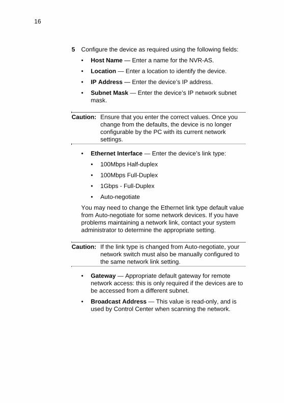
5 Configure the device as required using the following fields:
• Host Name — Enter a name for the NVR-AS.
• Location — Enter a location to identify the device.
• IP Address — Enter the device’s IP address.
• Subnet Mask — Enter the device’s IP network subnet mask.
Caution: Ensure that you enter the correct values. Once you change from the defaults, the device is no longer configurable by the PC with its current network settings.
• Ethernet Interface — Enter the device’s link type:
• 100Mbps Half-duplex
• 100Mbps Full-Duplex
• 1Gbps - Full-Duplex
• Auto-negotiate
You may need to change the Ethernet link type default value from Auto-negotiate for some network devices. If you have problems maintaining a network link, contact your system administrator to determine the appropriate setting.
Caution: If the link type is changed from Auto-negotiate, your network switch must also be manually configured to the same network link setting.
• Gateway — Appropriate default gateway for remote network access: this is only required if the devices are to be accessed from a different subnet.
• Broadcast Address — This value is read-only, and is used by Control Center when scanning the network.

17
• Recording Stream — Select the stream you want to use for recording. This is then used for all recording jobs on this NVR-AS.
When you have configured the device as required, click Submit to apply the changes to the device. You are now ready to take the device off the isolated network and connect it to the main network. See “Attaching the Device to the Network” on page 20.
6 If you need to configure another device, disconnect the cable from the device. Leave the cable connected to the PC.
Note: You may want to make a note of the device’s new IP address and subnet mask, or label the device with its new details.
7 Connect the crossover cable to the next device you want to configure.
8 Before you can access the next unit for configuration, type the following command from a Command Window:
C:> arp -d 10.5.1.10
9 Repeat these steps for each device, using different IP addresses for each device.
10 Ensure that no two devices share the same IP address (or that of the PC).

18
Using the Serial Port ConnectionTo configure your NVR-AS using the serial port, you require an RS232 serial cable.
1 Connect the serial cable between the NVR-AS and the PC as shown in Figure 7.
Figure 7 Serial port connection
2 On the PC, use a Terminal Emulation program such as Windows HyperTerminal and set the serial port parameters as follows:
• 115200 baud
• 8 bits
• No parity
• 1 stop bit
• Flow Control: None
3 Connect to the NVR-AS and press <Enter>. You should see the following prompt:
NVR-AS RD500 Version v3-12-0
Host Name : compactNVR-AS
Location : unknown
Ethernet : [ 10.5.1.10/255.0.0.0/10.0.0.1 ]
compactNVR-AS login:
4 Log in to the NVR-AS using the username "config" and password "config". The unit prompts you to enter the new configuration values. At each prompt, press <Enter> to accept the current value.
Serial cable
PCNVR-AS
1 2
Console Port

19
The following settings are available:
• IP Address — Enter the device’s IP address
• Subnet Mask — Enter the device’s IP network subnet mask.
• Gateway — Enter the appropriate default gateway for remote network access: this is only required if the devices are to be accessed from a different subnet.
• Link Type — Enter the device’s link type. The values are as follows:
• 100Mbps Half-duplex
• 100Mbps Full-Duplex
• 1Gbps - Full-Duplex
• Auto-negotiate
You may need to change the Ethernet link type default value from Auto-negotiate for some network devices. If you have problems maintaining a network link, contact your system administrator to determine the appropriate setting.
Caution: If the link type is changed from Auto-negotiate, your network switch must also be manually configured to the same network link setting.
• Host name — Enter a name to describe the unit.
• Location — Enter a name to describe the location of the unit.
• Reset network security to factory defaults — To reset all network security values to their defaults, select yes. This includes any restrictions you have set up using the Network Security web page, such as the web password.
You are now ready to attach the device to the network.

20
Attaching the Device to the NetworkAfter configuring the IP settings, connect it to the network.
1 Reconnect your PC to the network.
2 Use a standard RJ45 connector and CAT5 cable to connect to the ports on the rear of the device, as shown in Figure 8.
Figure 8 Connecting a device to the network
Once you have connected your NVR-AS to the network, you can carry out further configuration.
Further NVR-AS ConfigurationYou can carry out further configuration of the NVR-AS using the web configuration pages. For more information, see the Web Configuration Guide.
1 2
Console Port
Used forredundancy
NVR-ASPower Supply
PCNetwork

21
2 HARDWARE DESCRIPTION
This chapter describes the hardware for the NVR-AS units and the removable disk.
Warning: Do not attempt to service this product yourself as opening or removing covers may expose you to dangerous voltages. Refer all service to qualified service personnel.This apparatus must be earthed.When disconnecting the device, it is essential that you follow the steps in “NVR-AS Power Off Sequence” on page 9.
NVR-AS Front ViewFigure 9 shows the front of the NVR-AS
Figure 9 NVR-AS unit — front view
Compact NVR-AS 3000
Suspend/Resume CPU
1 2

22
The LEDs on the NVR-AS report activity and status.
NVR-AS Rear ViewFigure 10 shows the rear of the NVR-AS.
Figure 10 NVR-AS unit — rear view
Table 2 Chassis LED description
LED Name Status MeaningCPU Solid off Normal operation
Solid on CPU processing is too high
CPU + Alarm Flashing NVR-AS suspended
Activity (server status) Flashing Normal operation
Solid on/off Server failure
Link Port 1 / Link Port 2 Flashing Network activity
Off No network connection
On Network connection
Alarm Off Normal operation
On System failure
PS1 On Powered using internal PSU
PS2 On Powered using external PSU
1 2
Console Port

23
At the rear of the unit, there are ports to connect to the following:
• Power
• Port 1 network connector
• Port 2 network connector
• Serial RS-232 console port
Port 1 / Port 2 Network ConnectorThese port network connectors are RJ-45 connectors. These interfaces can be set to use fixed 100Mbps Half Duplex, 100Mbps Full Duplex, 1Gbps Full Duplex link, or can be set to auto-negotiate. They are used to record and play back media streams, as well as for web configuration pages.
For network redundancy both NVR-AS Ethernet ports can be connected to separate network switches. Only one port will be active at any time. If the active port becomes disconnected, then the other port will automatically be activated to maintain network connectivity, using the same IP address.
Serial RS-232 Console PortThe console port is an RS-232 interface, using the standard 9-pin DTE interface.
Note: Default console port settings are 115200 baud, 8-bits, no parity, 1 stop bit, no flow control.
Table 3 Serial port pinouts
Pin RS232 Function1 —
2 Rx
3 Tx
4 —
5 GND
6 —
7 —
8 —
9 —

24
Power The power inlet is a keyed two-pin interface which mates with the power supply unit supplied.
Removable Disk HardwareThe NVR-AS uses a 3.5“ SATA disk in a removable drive enclosure.
Caution: If you start the NVR-AS with no disk, the NVR-AS will start in the suspended state (CPU and Alarm LEDs flashing). When you insert the disk, the NVR-AS reboots and starts operating normally.
Figure 11 shows the front of the removable disk.
Figure 11 Removable disk
For information on removing and inserting disks, see “Changing Disks” on page 25
Release Button Release Lever
Disk Lock

25
3 USING THE REMOVABLE DISK
This chapter explains the following:
• Changing Disks
• Playing Back Recordings from an Archive Disk
• Protecting Recordings
• Checking a Disk
• Formatting a Disk
Changing DisksYou need to replace the disk if:
• the current disk is becoming full according to your maintenance schedule
• if an incident has occurred and you need to remove the disk on which it has been recorded and insert a new one
• the disk has developed a fault.
This section explains how to change disks — Table 4 on page 27 provides a summary of LED activity during this process.
Warning: Disks have a warranty of 5 years, but this warranty will be voided if the disk is removed from the caddy.Disks are not field replaceable. Faulty disks must be returned to IndigoVision as part of a caddy assembly. Individual disk and caddy assemblies required as spares or replacements can be ordered from IndigoVision.
Note: Before removing a disk, IndigoVision recommends that you protect the recordings on the disk to prevent accidental deletion when it is re-inserted. For information on protecting recordings, see “Protecting Recordings” on page 27.
26
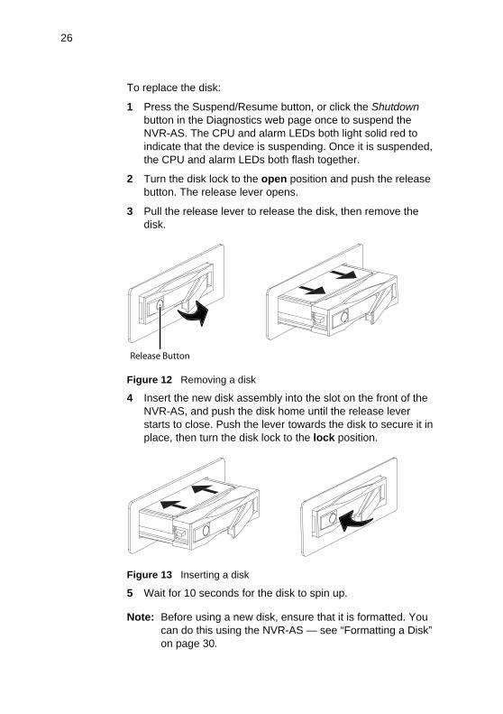
To replace the disk:
1 Press the Suspend/Resume button, or click the Shutdown button in the Diagnostics web page once to suspend the NVR-AS. The CPU and alarm LEDs both light solid red to indicate that the device is suspending. Once it is suspended, the CPU and alarm LEDs both flash together.
2 Turn the disk lock to the open position and push the release button. The release lever opens.
3 Pull the release lever to release the disk, then remove the disk.
Figure 12 Removing a disk
4 Insert the new disk assembly into the slot on the front of the NVR-AS, and push the disk home until the release lever starts to close. Push the lever towards the disk to secure it in place, then turn the disk lock to the lock position.
Figure 13 Inserting a disk
5 Wait for 10 seconds for the disk to spin up.
Note: Before using a new disk, ensure that it is formatted. You can do this using the NVR-AS — see “Formatting a Disk” on page 30.
Release Button

27
6 Press the Suspend/Resume button once to resume operation. The CPU LED stops flashing and goes out, but the alarm LED continues to flash. When the alarm LED stops flashing, the unit has resumed operation.
Protecting RecordingsIt is good practice to set all recordings on a disk to protected status before removing a disk which is to be archived. This means that when the disk is reinserted, recordings cannot be accidentally deleted or recorded over.
Note: Please be aware that if you protect all recordings, you lose the ability to identify recordings that were deliberately protected by the user in Control Center.
To protect all recordings on a disk:
1 Enter the IP address of the NVR-AS containing the disk into the URL field of a web browser.
Table 4 LED sequence
Action LED Activity MeaningPress Suspend/Resume button to suspend NVR-AS
CPU
Alarm
Solid red NVR-AS suspending
CPU
Alarm
Flash red NVR-AS suspended — safe to remove disk
Insert disk CPUAlarm
Flash red Disk inserted
Press Suspend/Resume button to resume NVR-AS
CPU Stops flashing
Resuming
Alarm Stops flashing
Resumed successfully

28
2 Click Disk from the options on the left. The Disk Configuration page opens.
Figure 14 Disk Configuration page
3 Click Protect All to protect all recordings and events on the current disk.
Click Unprotect All to allow all recordings and events to be deleted.
4 Click Submit.

29
Playing Back Recordings from an Archive DiskYou may need to review old recordings stored on an archive disk.
Warning: If you are using a single NVR-AS to record footage and to play back archived data, you must ensure that there are no active recording jobs or event filters on the NVR-AS and that time-based deletion of recordings (time and space reaping) is disabled (that is, space reaping is enabled). If you do not, archived footage may be deleted.For this reason it is good practice to protect all recordings before removing a disk which is to be archived. For more information, see “Protecting Recordings” on page 27.
To review archived recordings:
1 Enable space-based reaping in the Disk Configuration page (see Figure 14).
2 Suspend the NVR-AS and remove the current disk as described in “Changing Disks” on page 25.
3 Insert the archive disk as described in “Changing Disks” on page 25
4 Press the Suspend/Resume button to resume normal operation.

30
TroubleshootingThe following section describes actions that may be necessary when troubleshooting.
Checking a DiskTo check the integrity of the file structure contained on the current disk:
1 Open a DOS prompt.
2 Type telnet IP address
3 Log in as root, with password admin. (If you have set a password to allow web access, use this instead of admin.)
4 Type diskcheck.
Warning: The diskcheck command attempts to recover errors in the disk file structure. This may involve file deletion, which could result in lost recordings.
Formatting a DiskTo format the current disk:
1 Enter the IP address of the NVR-AS containing the disk into the URL field of a web browser.
2 Select Disk from the menu on the left. The Disk Configuration page opens.
3 Click Format Disk.
Warning: All data on a disk is erased when you re-format it.

31
4 HARDWARE SPECIFICATION
Video• Recording and playback of High Definition (HD) streams from
IndigoVision 10000 transmitters and receivers.
• Recording and playback of H.264 streams from IndigoVision 9000 transmitters and receivers.
• Recording and playback of MPEG4 Simple Profile streams from IndigoVision 8000 transmitters and receivers.
• H.261 video streams can be recorded and played back using IndigoVision 6000 transmitters and receivers running firmware version 4 and later.
Audio • Recording and playback of AAC-LC audio codec streams
from IndigoVision 8000, 9000, and 10000 transmitters and receivers.
• Audio streams from IndigoVision 6000 transmitters and receivers can be recorded and played back using IndigoVision 6000 devices running firmware version 4 and later.
StorageVarious disk capacity options are available. Please refer to the IndigoVision price list for full details.

32
Network Connections• IEEE 802.3 and IETF standards:
• 10/100/1000 Base-T Ethernet, TCP, UDP, ICMP and IGMP
• Physical connection via RJ-45
Performance
The NVR-AS may permit these maximum settings to be exceeded but at the risk of impairing its overall function.
NVR-AS Metrics
Dimensions• 45.3mm x 262.6mm x 255.5mm
Weight• 2.2Kg (max)
Feature MaximumRecording Streams 10
Recording Bandwidth 40 Mbps
Configured Recording Jobs 100
Total Number of Recordings 40,000
Number of Alarms 100,000
Playback Streams 5*
Playback Bandwidth 20 Mbps* A playback stream is required for displaying thumbnail images and carrying out motion search in Control Center

33
Power• Mains power supply unit operating voltages:
• Input: 100-240V ~ 47-63Hz 1.8A
• Output: 12Vdc 5A
• Power consumption: 32VA max
Removable Disk Metrics
Dimensions• 102mm x 147mm x 26.1mm
Weight• 1TB - 0.665Kg
• 500GB - 0.53Kg
Environment• Operating temperature 0 to +60°C/+32 to +140°F
• Storage temperature -20 to +70°C/-4 to +158°F
Regulatory• EN55022 ITE Emission Standard Class A
• EN61000-3-2 Mains Harmonics Class A
• EN61000-3-3 Voltage Fluctuation
• EN55024 ITE Immunity Standard
• CFR47: 2005 Part 15 Sub Part B (US federal code of regulations)
In accordance with the EC Waste Electrical and Electronic Equipment (WEEE) directive 2002/96/EC this product must be sent to a recycling plant for proper disposal at the end of its use.

34

35
A GNU GENERAL PUBLIC LICENCE
IndigoVision's NVR-AS products use code that is freely available under the GNU General Public Licence (GPL).
This licence makes it a requirement to release changes made to the source code. In compliance, the GPL source code and any changes made by Indigovision are available on request through IndigoVision Customer Support.

36

37
INDEX
Aarchived disks 29archiving disks 9attaching NVR-AS to network 20audio specification 31
Cchanging disks 25changing PC settings 13checking disks 30configuration
prerequisites 11using serial port 18using the Web Configuration
pages 11configuring NVR-AS 14connectors
network 32network ports 23power 24serial port 23
console port 23default settings 23
Ddefault IP properties 11dimensions
disk 33dimentions
disks 33unit 32
disconnecting the NVR-AS 21disks
archive 29changing 25checking 30dimensions 33formatting 30inserting 26
protecting recordings 27removing 26SATA 24
Eenvironmental specification 33
Fformatting disks 30front view 21
Ggeneral public licence 35
Hhardware
NVR-AS 21removable disk 24
Iinserting disks 26IP properties 11
changing using serial port 18isolated network, preparing 12
LLEDs
NVR-AS 22
Mmains power supply
operating voltage 33metrics 32, 33
38
Nnetwork
connections 32ports 23
NVR-ASattaching to network 20configuration 14configuration, advanced 20disconnecting 21front view 21hardware 21LEDs 22overview 7rear view 22usage 9
Ooperating voltage 33overview of NVR-AS 7
PPC settings, changing 13performance maximums 32power
unit 33power connector 24power off sequence 9power up sequence 8preparing
isolated network 12PC for initial device
configuration 13prerequisites for configuration 11protecting recordings 27
Rrear view 22recordings
protecting 27unprotecting 27
regulatory specification 33removable disk
changing 25hardware 24inserting 25, 26
removingdisk 26evidence of incident 10
reusing same disk 9
SSATA disks 24serial RS-232 console port 23specifications
audio 31environmental 33regulatory 33storage 31video 31
storage specifications 31
Ttroubleshooting 30
Uunit
metrics 32unprotecting recordings 27usage
archiving disks 9removing disks 10reusing same disk 9
Vvideo specification 31
WWeb Configuration pages 11weight
disks 33unit 32

39

Document ID: IU-NVR-COM-MAN001-4