Embed Size (px)
Citation preview

SERIALNUMBER:___________________ ManualNumber:51-10034 Models:10705 MODELNUMBER:___________________ Rev.2
OPERATOR’S&PARTSMANUAL
COMPACTTRACTORDEBRISBUCKET
800-456-7100 I www.paladinlcg.com 503 Gay Street, Delhi, IA 52223, United States of America
02/16/09


02/16/09 51-10034 1
TABLE OF CONTENTS
INTRODUCTION ............................................................................................................... 2
GENERAL INFORMATION ................................................................................................ 2
SERIAL NUMBER .............................................................................................................. 2
OWNER AND OPERATOR SAFETY INFORMATION SAFETY STATEMENTS .......................................................................................... 3 SAFETY PRECAUTIONS ....................................................................................... 3-5 SAFETY SIGNS ...................................................................................................... 6-7
SPECIFICATIONS ............................................................................................................. 8-9
MOUNTING ....................................................................................................................... 10
OPERATION ...................................................................................................................... 11
MAINTENANCE ................................................................................................................. 12
SERVICE ............................................................................................................................ 12
MAINTENANCE RECORD LOG ........................................................................................ 13
PARTS ILLUSTRATION ..................................................................................................... 14
PARTS LIST ....................................................................................................................... 15
WARRANTY ........................................................................................................................ i

02/16/0951-100342
INTRODUCTION
Congratulations on your purchase of a new FFC Compact Tractor Debris Bucket. This product has been designed and built to pick up bulky, unusually shaped, or long materials that would not stay in an ordinary bucket. You or any other person who will be assembling, operating, maintaining, or working with this product are required to read and completely understand the information and instructions contained in this manual. If anyone does not fully understand every part of this manual, please obtain further assistance by contacting the dealer from which this product was purchased or by contacting FFC at the telephone number or address listed on the cover of this manual. Keep this manual available for reference whenever this product is being handled or used. Provide this manual to any new owners and/or operators.This manual covers model(s) 10705.
GENERAL INFORMATIONThe purpose of this manual is to assist in assembling, mounting, operating, and maintaining your attachment. Read this manual carefully to obtain valuable information and instructions that will help you achieve years of safe and dependable service.The illustrations and data used in this manual were current at the time of printing, but due to possible engineering and/or production changes, this product may vary slightly in detail. FFC reserves the right to redesign and/or change components as may be necessary without notifi cation to anyone.Throughout this manual, references may be made to:
Tractor The engine-driven machine to which this product must be attached.Right, Left, Front, Rear
Directions that are determined in relation to the operator of the equipment when seated in the normal operation position.
IMPORTANT Precautions that must be followed to prevent substandard performance.
SERIAL NUMBER LOCATIONAlways refer to the model and serial number when ordering parts or requesting information from your dealer. See Safety Signs section for the location of the serial number plate for this product.
Reference InformationModel Number Tractor Make & ModelSerial Number Loader ModelDate Purchased Loader Serial Number
02/16/09 51-10034 3
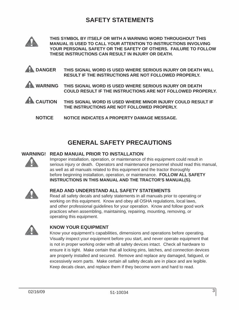
SAFETY STATEMENTS
THIS SYMBOL BY ITSELF OR WITH A WARNING WORD THROUGHOUT THIS MANUAL IS USED TO CALL YOUR ATTENTION TO INSTRUCTIONS INVOLVING YOUR PERSONAL SAFETY OR THE SAFETY OF OTHERS. FAILURE TO FOLLOW THESE INSTRUCTIONS CAN RESULT IN INJURY OR DEATH.
DANGER THIS SIGNAL WORD IS USED WHERE SERIOUS INJURY OR DEATH WILL RESULT IF THE INSTRUCTIONS ARE NOT FOLLOWED PROPERLY.
WARNING THIS SIGNAL WORD IS USED WHERE SERIOUS INJURY OR DEATH COULD RESULT IF THE INSTRUCTIONS ARE NOT FOLLOWED PROPERLY.
CAUTION THIS SIGNAL WORD IS USED WHERE MINOR INJURY COULD RESULT IF THE INSTRUCTIONS ARE NOT FOLLOWED PROPERLY.
NOTICE NOTICE INDICATES A PROPERTY DAMAGE MESSAGE.
GENERAL SAFETY PRECAUTIONSWARNING! READ MANUAL PRIOR TO INSTALLATION Improper installation, operation, or maintenance of this equipment could result in serious injury or death. Operators and maintenance personnel should read this manual, as well as all manuals related to this equipment and the tractor thoroughly before beginning installation, operation, or maintenance. FOLLOW ALL SAFETY INSTRUCTIONS IN THIS MANUAL AND THE TRACTOR'S MANUAL(S).
READ AND UNDERSTAND ALL SAFETY STATEMENTS Read all safety decals and safety statements in all manuals prior to operating or working on this equipment. Know and obey all OSHA regulations, local laws, and other professional guidelines for your operation. Know and follow good work practices when assembling, maintaining, repairing, mounting, removing, or operating this equipment. KNOW YOUR EQUIPMENT Know your equipment’s capabilities, dimensions and operations before operating. Visually inspect your equipment before you start, and never operate equipment that is not in proper working order with all safety devices intact. Check all hardware to ensure it is tight. Make certain that all locking pins, latches, and connection devices are properly installed and secured. Remove and replace any damaged, fatigued, or excessively worn parts. Make certain all safety decals are in place and are legible. Keep decals clean, and replace them if they become worn and hard to read.

02/16/0951-100344
GENERAL SAFETY PRECAUTIONS
WARNING! PROTECT AGAINST FLYING DEBRIS Always wear proper safety glasses, goggles or a face shield when driving pins in or out, or when any operation causes dust, flying debris, or any other hazardous material.
WARNING! LOWER OR SUPPORT RAISED EQUIPMENT Do not work under raised booms without supporting them. Do not use support material made of concrete blocks, logs, buckets, barrels or any other material that could suddenly collapse or shift positions. Make sure support material is solid, not decayed, warped, twisted, or tapered. Lower booms to ground level or onto blocks. Lower booms and attachments to the ground before leaving the cab or operator’s station.
WARNING! USE CARE WITH HYDRAULIC FLUID PRESSURE Hydraulic fluid under pressure can penetrate the skin and cause serious injury or death. Hydraulic leaks under pressure may not be visible. Before connecting or disconnecting hydraulic hoses, read your tractors operator’s manual for detailed instructions on connecting and disconnecting hydraulic hoses or fittings. • Keep unprotected body parts, such as face, eyes, and arms as far away as possible from a suspected leak. Flesh injected with hydraulic fluid may develop gangrene or other permanent disabilities. • If injured by injected fluid, see a doctor at once. If your doctor is not familiar with this type of injury, ask him to research immediately to determine proper treatment. • Wear safety glasses, protective clothing, and use a sound piece of cardboard or wood when searching for hydraulic leaks. DO NOT USE YOUR HANDS! SEE ILLUSTRATION.
CARDBOARD
HYDRAULIC HOSEOR FITTING
MAGNIFYING GLASS

02/16/09 51-10034 5
GENERAL SAFETY PRECAUTIONS
WARNING! DO NOT MODIFY MACHINE OR ATTACHMENTS Modifications may weaken the integrity of the attachment and may impair the function, safety, life, and performance of the attachment. When making repairs, use only the manufacturer’s genuine parts, following authorized instructions. Other parts may be substandard in fit and quality. Never modify any ROPS (Roll Over Protection Structure) or FOPS (Falling Object Protective Structure) equipment or device. Any modifications must be authorized in writing by the manufacturer.
WARNING! SAFELY MAINTAIN AND REPAIR EQUIPMENT • Do not wear loose clothing, or any accessories that can catch in moving parts. If you have long hair, cover or secure it so that it does not become entangled in the equipment. • Work on a level surface in a well-lit area. • Use properly grounded electrical outlets and tools. • Use the correct tool for the job at hand. Make sure they are in good condition for the task required. • Wear the protective equipment specified by the tool manufacturer.
WARNING! SAFELY OPERATE EQUIPMENT Do not operate equipment until you are completely trained by a qualified operator in how to use the controls, know its capabilities, dimensions, and all safety requirements. See your machine's manual for these instructions. • Keep all step plates, grab bars, pedals, and controls free of dirt, grease, debris, and oil. • Never allow anyone to be around the equipment when it is operating. • Do not allow riders on the attachment or the tractor. • Do not operate the equipment from anywhere other than the correct operators position. • Never leave equipment unattended with the engine running or with this attachment in a raised position. • Do not alter or remove any safety feature from the tractor or this attachment. • Know your work site safety rules as well as traffic rules and flow. When in doubt on any safety issue, contact your supervisor or safety coordinator for an explanation.
WARNING! KNOW WHERE UTILITIES ARE Observe overhead electrical and other utility lines. Be sure equipment will clear them. When digging, call your local utilities for location of buried utility lines, gas, water, and sewer, as well as any other hazard you may encounter.
02/16/0951-100346
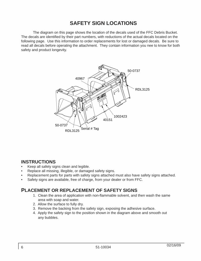
SAFETY SIGN LOCATIONS The diagram on this page shows the location of the decals used of the FFC Debris Bucket. The decals are identified by their part numbers, with reductions of the actual decals located on the following page. Use this information to order replacements for lost or damaged decals. Be sure to read all decals before operating the attachment. They contain information you nee to know for both safety and product longevity.
INSTRUCTIONS• Keep all safety signs clean and legible.• Replace all missing, illegible, or damaged safety signs.• Replacement parts for parts with safety signs attached must also have safety signs attached.• Safety signs are available, free of charge, from your dealer or from FFC. PLACEMENT OR REPLACEMENT OF SAFETY SIGNS 1. Clean the area of application with non-flammable solvent, and then wash the same area with soap and water. 2. Allow the surface to fully dry. 3. Remove the backing from the safety sign, exposing the adhesive surface. 4. Apply the safety sign to the position shown in the diagram above and smooth out any bubbles.
1002423
40967
40151
Serial # Tag50-0737
RDL3125
RDL3125
50-0737

02/16/09 51-10034 7
SAFETY SIGNS
PART # 40151WARNING! HIGH PRESSURE FLUIDPART # 1002423
WARNING! READ MANUAL
PART # 40967WARNING! SPECIFICATIONS
PART # 50-0737WARNING! PINCH POINT
PART # RDL3125WARNING! CRUSH HAZARD

02/16/0951-100348
TRACTOR/LOADER SPECIFICATIONS
IMPORTANT Exceeding any of the maximum recommended tractor/loader specifications CAN result in damage to this product and WILL void all FFC warranties.
DESCRIPTION SPECIFICATIONSTractor HP 40 HP maximumOperating Weight of Tractor 4,000 lbs. maximumLift Capacity of Tractor's Loader 2,000 lbs. maximumRear Ballast As required to maintain full tractor stability.
(Note the shipping weight of your model, then see the operator’s manual(s) for your tractor and loader for ballasting needs.)
ATTACHMENT SPECIFICATIONSModel
NumberOverallWidth
OverallHeight
OverallDepth
Grapple Opening
Shipping Weight
10705-60 62.4" 28.7" 32.5" 32.5" 560#10705-66 66.6" 28.7" 32.5" 32.5" 595#
10705-72 72.8" 29" 34.5" 34.7" 635#

02/16/09 51-10034 9
BOLT TORQUEBOLT TORQUE SPECIFICATIONS
GENERAL TORQUE SPECIFICATION TABLES
given. Always use grade 5 or better when replacing bolts.
SAE BOLT TORQUE SPECIFICATIONSNOTE: The following torque values are for use with extreme pressure lubricants, plating or hard washer applications Increase torque 15% when using hardware that is unplated and either dry or lubricated with engine oil.
Bolt SizeSAE GRADE 5 TORQUE SAE GRADE 8 TORQUE
Pounds Feet Newton-Meters Pounds Feet Newton-Meters NOTE: Manufacturing Marks Will VaryInches Millimeters UNC UNF UNC UNF UNC UNF UNC UNF
1/4 6.35 8 9 11 12 10 13 14 185/16 7.94 14 19 19 23 20 25 27 343/8 9.53 30 36 41 49 38 46 52 62
7/16 11.11 46 54 62 73 60 71 81 961/2 12.70 68 82 92 111 94 112 127 152
9/16 14.29 94 112 127 152 136 163 184 2215/8 15.88 128 153 174 207 187 224 254 3043/4 19.05 230 275 312 373 323 395 438 5367/8 22.23 340 408 461 553 510 612 691 8301 25.40 493 592 668 803 765 918 1037 1245
1-1/8 25.58 680 748 922 1014 1088 1224 1475 16601-1/4 31.75 952 1054 1291 1429 1547 1700 2097 23051-3/8 34.93 1241 1428 1683 1936 2023 2312 2743 31351-1/2 38.10 1649 1870 2236 2535 2686 3026 3642 4103
METRIC BOLT TORQUE SPECIFICATIONSNOTE: The following torque values are for use with metric hard-ware that is unplated and either dry or lubricated with engine oil.Reduce torque 15% when using hardware that has extreme pressure lubricants, plating or hard washer applications.
Size of Bolt Grade No. Pitch (mm) Pounds Feet Newton-Meters Pitch (mm) Pounds Feet Newton-Meters5.6 3.6-5.8 4.9-7.9 - -
M6 8.8 1.0 5.8-.4 7.9-12.7 - - -10.9 7.2-10 9.8-13.6 - -5.6 7.2-14 9.8-19 12-17 16.3-23
M8 8.8 1.25 17-22 23-29.8 1.0 19-27 25.7-36.610.9 20-26 27.1-35.2 22-31 29.8-425.6 20-25 27.1-33.9 20-29 27.1-39.3
M10 8.8 1.5 34-40 46.1-54.2 1.25 35-47 47.4-63.710.9 38-46 51.5-62.3 40-52 54.2-70.55.6 28-34 37.9-46.1 31-41 42-55.6
M12 8.8 1.75 51-59 69.1-79.9 1.25 56-68 75.9-92.110.9 57-66 77.2-89.4 62-75 84-101.65.6 49-56 66.4-75.9 52-64 70.5-86.7
M14 8.8 2.0 81-93 109.8-126 1.5 90-106 122-143.610.9 96-109 130.1-147.7 107-124 145-1685.6 67-77 90.8-104.3 69-83 93.5-112.5
M16 8.8 2.0 116-130 157.2-176.2 1.5 120-138 162.6-18710.9 129-145 174.8-196.5 140-158 189.7-214.15.6 88-100 119.2-136 100-117 136-158.5
M18 8.8 2.0 150-168 203.3-227.6 1.5 177-199 239.8-269.610.9 175-194 237.1-262.9 202-231 273.7-3135.6 108-130 146.3-176.2 132-150 178.9-203.3
M20 8.8 2.5 186-205 252-277.8 1.5 206-242 279.1-327.910.9 213-249 288.6-337.4 246-289 333.3-391.6

02/16/0951-1003410
MOUNTING WARNING! READ MANUAL PRIOR TO INSTALLATION Improper installation, operation, or maintenance of this equipment could result in serious injury or death. Operators and maintenance personnel should read this manual, as well as all manuals related to this equipment and the tractor/loader thoroughly before beginning installation, operation, or maintenance. FOLLOW ALL SAFETY INSTRUCTIONS IN THIS MANUAL AND THE TRACTOR'S MANUAL(S). 1. Place this product on a firm, level surface that is large enough to safely accommodate this product, your tractor/loader and all workers involved in the mounting process.2. Refer to the operator’s manual(s) for your tractor and loader. Follow the mounting instructions contained therein.3. Carefully raise the loader and cycle the tilt cylinders to check clearances and to verify that all mounting procedures have been successfully completed.

02/16/09 51-10034 11
OPERATION
Read all Safety Precautions before operating your new attachment.Refer to your machines operator's manual for attachment operation.
The debris buckets are designed to pick up bulky, unusually shaped, or long materials that would not stay in an ordinary bucket. 1. Approach the load in such a fashion that the weight will be centered on the floor of the bucket. The heaviest side should be closest to the back of the bucket and not near the bucket edge.2. Before lifting, make certain the bucket is completely under the load and the bucket floor is level.3. Close the grapples to their fullest extent possible and lift the bucket slightly to be certain that the load is secure.
NOTE: If the load appears to be unstable, lower the bucket to the ground, open the grapples and reposition the load to attain full stability. Repeat until full stability is achieved.
When using the grapples as a rake to drag materials into position for pick up, THE GRAPPLES MUST BE COMPLETELY OPEN.
NOTICE Applying a raking-type force to partially open grapples will greatly magnify the fluid pressure in the hydraulic hoses, fittings, and cylinders and may cause component failure.
Never heap load heavy material where the combined weight of the attachment and material could exceed the rated lifting capacity of the loader. Be sure the load does not stick out too far in front of the bucket. A light load sticking out too far can have the same tipping effect as a heavy load carried in close. Operate the attachment only when properly seated at the operator's station. Do not exceed the lift capacity of your loader. See loader specifications. Do not handle round bales. When using the grapple, lift the load slightly and make sure that the load is secure. If the load appears to be unstable, lower the load, open the grapple and reposition the load to attain full stability. Reduce speed when driving over rough terrain, on a slope, or turning, to avoid overturning the vehicle. Avoid side slope travel whenever possible. Drive up the slope to pick up a load and then down in reverse. Carry loads as close to the ground as possible. Before exiting the prime mover, lower the bucket to the ground, turn off the prime mover's engine, remove the key and apply the brakes. Do not detach loader from tractor with this attachment installed. Equip loader with materials bucket when detaching.

02/16/0951-1003412
MAINTENANCE
KNOW YOUR EQUIPMENT Know your equipment’s capabilities, dimensions and operations before operating. Visually inspect your equipment before you start, and never operate equipment that is not in proper working order with all safety devices intact. Check all hardware to ensure it is tight. Make certain that all locking pins, latches, and connection devices are properly installed and secured. Remove and replace any damaged, fatigued, or excessively worn parts. Make certain all safety decals are in place and are legible. Keep decals clean, and replace them if they become worn and hard to read.
BEFORE EACH USE
• Make sure that all nuts and bolts are in place and properly tightened.• Make sure that all other fasteners are in place and are performing their specified function.• Make sure that all safety signs are in place, are clean, and are legible. • Replace any damaged parts and excessively worn parts.
IMPORTANT: When replacing parts, use only factory approved replacement parts. Manufacturer will not claim responsibility for use of unapproved parts or accessories and/or other damages as a result of their use.
LUBRICATION The only lubrication your attachment may need is the greasing of the cylinder ends and pivot points. A grease fitting has been installed to facilitate this task. We recommend greasing all grease fittings after the initial 8 hours of operation and then every 40 hours of operation thereafter.
DAILY OR EVERY 8 HOURS OF OPERATION Replace any missing bolts or nuts with approved replacement parts. Check hydraulic system for leaks. (If so equipped.) Visually inspect the machine for worn parts or cracked welds. Repair as necessary. Replace any damaged, illegible or missing decals.
SERVICEWARNING! DO NOT MODIFY MACHINE OR ATTACHMENTS Modifications may weaken the integrity of the and may impair the function, safety, life, and performance of the . When making repairs, use only the manufacturer’s genuine parts, following authorized instructions. Other parts may be substandard in fit and quality. Never modify any ROPS (Roll Over Protection Structure) or FOPS (Falling Object Protective Structure) equipment or device. Any modifications must be authorized in writing by the manufacturer.

02/16/09 51-10034 13
MAINTENANCE
MAINTENANCE RECORD
Use this log to record maintenance performed on the attachment.
Date Maintenance Procedure Performed
Performed by Comments

02/16/0951-1003414
DEBRIS BUCKET PARTS ILLUSTRATION
15
16
17
7
16
19
2325 23
1
8
1
10
1324
1822
2426 2224
1812
242620
24
1822
11
2426
2123
4 2
1
1
156
5
9
14

02/16/09 51-10034 15
DEBRIS BUCKET PARTS LIST
ITEM QTY. 10705-60 10705-66 10705-72 DESCRIPTION
1 6 30204 90° Elbow 6MB-6MF2 2 03-10107 Hose .25 x 44" 6FF-6FF Sheathed3 1 03-10108 Hose .25 x 50" 6FF-6FF Sheathed4 1 03-10109 Hose .25 x 36" 6FF-6FF Sheathed5 2 30381 Tee 6MF-6MF-6FF6 2 30380 90° Elbow 6MB-6MF Long7 2 03-10115 Hose .25 x 60" 6FF-6MB Sheathed8 2 107865 Hydraulic Cylinder 2 x 8.5 x 1.25 3000psi9 1 13-52273 13-52273 13-52241 Grapple Weldment RH
10 1 13-52274 13-52274 13-52242 Grapple Weldment LH11 1 13-52287 13-52798 13-52243 Bucket Weldment12 2 13-52369 Pivot Pin Weldment 3.47 ZDC13 2 13-52370 Pivot Pin Weldment 4.47 ZDC14 2 13-52371 Pivot Pin Weldment 23.19 ZDC*15 2 3338 Adaptor 6FB-8MB*16 1 17139 QD Male 8FBO PP .50 BODY*17 1 17140 QD Female 8FBO PP .50 BODY18 6 81595 Tube Rnd .62 x .385 x .44 YDC19 1 88536 Valve Pilot Operated Double Check20 2 34114 Hose Guard 5"21 2 1027 Grade 5 Hex Head Cap Screw .31" x 2.25"22 6 1045 Grade 5 Hex Head Cap Screw .38" x 1.5"23 4 1513 Grade 5 Flat Washer USS .31"24 12 1525 Grade 5 Flat Washer SAE .38"25 2 1934 Grade 5 Center Dent Lock Nut .31"26 6 1837 Grade 5 Center Dent Lock Nut .38"
NOTE: All parts are the same as 10705-72 except for those parts numbered under the other models.*ITEM may vary per tractor/loader -- Contact FFC for correct item.
.

Limited WarrantyExcept for the Excluded Products as described below, all new products are warranted to be free from defects in material and/or workmanship during the Warranty Period, in accordance with and subject to the terms and conditions of this Limited Warranty.
1. Excluded Products. The following products are excluded from this Limited Warranty:
(a) Any cable, part that engages with the ground (i.e. sprockets), digging chain, bearing, teeth, tamping and/or demolition head, blade cutting edge, pilot bit, auger teeth and broom brush that either constitutes or is part of a product.
(b) Any product, merchandise or component that, in the opinion of Paladin Light Construction1, has been (i) misused; (ii) modified in any unauthorized manner; (iii) altered; (iv) damaged; (v) involved in an accident; or (vi) repaired using parts not obtained through Paladin Light Construction.
2. Warranty Period. The Limited Warranty is provided only to those defects that occur during the Warranty Period, which is the period that begins on the first to occur of: (i) the date of initial purchase by an end-user, (ii) the date the product is first leased or rented, or (iii) the date that is six (6) months after the date of shipment by Paladin Light Construction as evidenced by the invoiced shipment date (the “Commencement Date”) and ends on the date that is twelve (12) months after the Commencement Date.
3. Terms and Conditions of Limited Warranty. The following terms and conditions apply to the Limited Warranty hereby provided:
(a) Option to Repair or Replace. Paladin Light Construction shall have the option to repair or replace the product.
(b) Timely Repair and Notice. In order to obtain the Limited Warranty, (i) the product must be repaired within thirty (30) days from the date of failure, and (ii) a claim under the warranty must be submitted to Paladin Light Construction in writing within thirty (30) days from the date of repair.
(c) Return of Defective Part or Product. If requested by Paladin Light Construction, the alleged defective part or product shall be shipped to Paladin Light Construction at its manufacturing facility or other location specified by Paladin Light Construction, with freight PRE-PAID by the claimant, to allow Paladin Light Construction to inspect the part or product.
Claims that fail to comply with any of the above terms and conditions shall be denied.
LIMITATIONS AND EXCLUSIONS.
THIS LIMITED WARRANTY IS IN LIEU OF ALL OTHER WARRANTIES, EXPRESS OR IMPLIED, INCLUDING WITHOUT LIMITATION THE WARRANTIES OF MERCHANTABILITY, FITNESS FOR A PARTICULAR PURPOSE AND ANY WARRANTY BASED ON A COURSE OF DEALING OR USAGE OF TRADE.
IN NO EVENT SHALL PALADIN LIGHT CONSTRUCTION BE LIABLE FOR CONSEQUENTIAL OR SPECIAL DAMAGES.
IN NO EVENT SHALL PALADIN LIGHT CONSTRUCTION BE LIABLE FOR ANY LOSS OR CLAIM IN AN AMOUNT IN EXCESS OF THE PURCHASE PRICE, OR, AT THE OPTION OF PALADIN LIGHT CONSTRUCTION, THE REPAIR OR REPLACEMENT, OF THE PARTICULAR PRODUCT ON WHICH ANY CLAIM OF LOSS OR DAMAGE IS BASED. THIS LIMITATION OF LIABILITY APPLIES IRRESPECTIVE OF WHETHER THE CLAIM IS BASED ON BREACH OF CONTRACT, BREACH OF WARRANTY, NEGLIGENCE OR OTHER CAUSE AND WHETHER THE ALLEGED DEFECT IS DISCOVERABLE OR LATENT.
1Attachment Technologies Inc., a subsidiary of Paladin Brands Holding, Inc. (PBHI) is referred to herein as Paladin Light Construction.
February 10, 2010