Embed Size (px)
Citation preview

CompactBlock LDX I/O
TECHNICAL DATA
1790D SERIES


3 Publication 1790D-TD001D-EN-P - June 2008
Table of Contents
PrefaceAbout This Publication . . . . . . . . . . . . . . . . . . . . . . . . . . . . . . . . . . . . . . 5Additional Resources . . . . . . . . . . . . . . . . . . . . . . . . . . . . . . . . . . . . . . . . 5
Chapter 1CompactBlock LDX I/O for the DeviceNet Network
Introduction . . . . . . . . . . . . . . . . . . . . . . . . . . . . . . . . . . . . . . . . . . . . . . . 7Features. . . . . . . . . . . . . . . . . . . . . . . . . . . . . . . . . . . . . . . . . . . . . . . . . . 10
Benefits. . . . . . . . . . . . . . . . . . . . . . . . . . . . . . . . . . . . . . . . . . . . . . . 10Typical Configuration . . . . . . . . . . . . . . . . . . . . . . . . . . . . . . . . . . . . . . 11System Compatibility . . . . . . . . . . . . . . . . . . . . . . . . . . . . . . . . . . . . . . . 11CompactBlock LDX I/OFamily Module Communication . . . . . . . . . . . . . . . . . . . . . . . . . . . . . . 11
Polled . . . . . . . . . . . . . . . . . . . . . . . . . . . . . . . . . . . . . . . . . . . . . . . . 11Cyclic . . . . . . . . . . . . . . . . . . . . . . . . . . . . . . . . . . . . . . . . . . . . . . . . 12Change-of-state . . . . . . . . . . . . . . . . . . . . . . . . . . . . . . . . . . . . . . . . 12
Software and EDS File Requirements. . . . . . . . . . . . . . . . . . . . . . . . . . 12Status Indicators . . . . . . . . . . . . . . . . . . . . . . . . . . . . . . . . . . . . . . . . . . . 13
Module/Network Status Indicators - All Base Modules . . . . . . . . 14I/O Status Indicators - Digital Base and Expansion Modules . . . 14I/O Status Indicators - Analog Base Modules . . . . . . . . . . . . . . . . 15I/O Status Indicators - Analog Base Modules . . . . . . . . . . . . . . . . 15I/O Status Indicators - RTD and Thermocouple Base Modules . 16
Power Supply Requirements . . . . . . . . . . . . . . . . . . . . . . . . . . . . . . . . . 16Mounting . . . . . . . . . . . . . . . . . . . . . . . . . . . . . . . . . . . . . . . . . . . . . . . . 16CompactBlock LDX I/O Accessories and DeviceNet Cables . . . . . . 18
Chapter 2DeviceNet Digital and Analog D-Shell Blocks
General Specifications . . . . . . . . . . . . . . . . . . . . . . . . . . . . . . . . . . . . . . 19Module Information. . . . . . . . . . . . . . . . . . . . . . . . . . . . . . . . . . . . . . . . 20
24V dc 16 Sourcing Output Base and Expansion Modules (1790D-0B16 and 1790-0B16X) . . . . . . . . . . . . . . . . . . . . . . . . 21
24V dc 16 Sinking Output Base and Expansion Modules (1790D-0V16 and 1790-0V16X). . . . . . . . . . . . . . . . . . . . . . . . 22
6-relay Output Base Module (1790D-0W6) . . . . . . . . . . . . . . . . . . 238-relay Output Expansion Module - 1790-0W8X . . . . . . . . . . . . . 2424V dc 16 Universal Input Base and Expansion Modules
(1790D-16BV0 and 1790-16BV0X) . . . . . . . . . . . . . . . . . . . . . 2524V dc 8 Universal Input/8 Sourcing Output Base and
Expansion Modules (1790D-8BV8B and 1790-8BV8BX) . . . 2724V dc 8 Universal Input/8 Sinking Output Base and
Expansion Modules (1790D-8BV8V and 1790-8BV8VX) . . . 294-channel Input RTD Base Module (1790D-4R0) . . . . . . . . . . . . . 314-channel Input Thermocouple Base Module (1790D-4T0) . . . . . 332-channel Analog Current Output Module (1790D-N0C2) . . . . . 352-channel Analog Voltage Output Module (1790D-N0V2) . . . . . 36

Publication 1790D-TD001D-EN-P - June 2008
Table of Contents 4
4-channel Analog Current Input Module (1790D-N4C0) . . . . . . . 374-channel Analog Voltage Input Module (1790D-N4V0) . . . . . . . 39
Chapter 3DeviceNet Digital and Analog Terminal Blocks
General Specifications . . . . . . . . . . . . . . . . . . . . . . . . . . . . . . . . . . . . . . 41Module Information. . . . . . . . . . . . . . . . . . . . . . . . . . . . . . . . . . . . . . . . 42
120V ac, 6 Output Base Module (1790D-T0A6) . . . . . . . . . . . . . . 43120V ac, 8 Output Base Module (1790-T0A8X) . . . . . . . . . . . . . . 4424V dc 16 Sourcing Output Base and Expansion Modules
(1790D-T0B16 and 1790-T0B16X) . . . . . . . . . . . . . . . . . . . . . 4524V dc 32 Sourcing Output Base Module (1790D-T0B32). . . . . . 4624V dc 16 Sinking Output Base and Expansion Modules
(1790D-T0V16 and 1790-T0V16X) . . . . . . . . . . . . . . . . . . . . . 4824V dc 32 Sinking Output Base Module (1790D-T0V32). . . . . . . 496 Relay Output Base Module (1790D-T0W6) . . . . . . . . . . . . . . . . 518 Relay Output Expansion Module (1790-T0W8X) . . . . . . . . . . . 5224V dc 16 Universal Input Base and Expansion Modules
(1790D-T16BV0 and 1790-T16BV0X) . . . . . . . . . . . . . . . . . . 5324V dc 32 Universal Input Base Module (1790D-T32BV0) . . . . . 55120V ac 8 Input Base and Expansion Modules
(1790D-T8A0 and 1790-T8A0X) . . . . . . . . . . . . . . . . . . . . . . . 5724V dc 8 Universal Input/8 Sourcing Output Base and Expansion
Modules (1790D-T8BV8B and 1790-T8BV8BX) . . . . . . . . . . 5924V dc 16 Universal Input/16 Sourcing Output Base Module
(1790D-T16BV16B) . . . . . . . . . . . . . . . . . . . . . . . . . . . . . . . . . 6124V dc 8 Universal Input/8 Sinking Output Base and Expansion
Modules (1790D-T8BV8V and 1790-T8BV8VX). . . . . . . . . . 6324V dc 16 Universal Input/16 Sinking Output Base Module
(1790D-T16BV16V) . . . . . . . . . . . . . . . . . . . . . . . . . . . . . . . . . 654 Channel Input RTD Base Module (1790D-T4R0) . . . . . . . . . . . 674 Channel Input Thermocouple Base Module (1790D-T4T0) . . . 692 Channel Analog Current Output Module (1790D-TN0C2). . . . 712 Channel Analog Voltage Output Module (1790D-TN0V2). . . . 724 Channel Analog Current Input Module (1790D-TN4C0) . . . . . 734 Channel Analog Voltage Input Module (1790D-TN4V0) . . . . . 75

5 Publication 1790D-TD001D-EN-P - June 2008
Preface
About This Publication This publication provides detailed technical information on the CompactBlock LDX I/O for DeviceNet modules.
Additional Resources The publications listed in this table contain more information on CompactBlock LDX I/O modules as well as the DeviceNet network and its products.
You can view or download publications at http://literature.rockwellautomation.com. To order paper copies of technical documentation, contact your local Rockwell Automation distributor or sales representative.
Related Publications for CompactBlock LDX I/O Modules
Pub. Title Pub. Number
IP20 Block I/O Selection Guide 1790-SG001
1790 CompactBlock LDX I/O Product Profile 1790-PP002
CompactBlock LDX Analog Modules User Manual 1790-UM001
CompactBlock LDX I/O for DeviceNet Technical Data 1790D-TD001
CompactBlock LDX I/O for PROFIBUS DP Technical Data 1790P-TD001
CompactBlock LDX RTD/Resistance Input Module User Manual 1790-UM002
CompactBlock LDX I/O Thermocouple Modules User Manual 1790-UM003
DeviceNet Analog Base D-Shell CompactBlock LDX I/O Installation Instructions
1790-IN004
DeviceNet Analog Base Terminal Block CompactBlock LDX I/O Installation Instructions
1790-IN002
DeviceNet Digital Base D-Shell Block CompactBlock LDX I/O Installation Instructions
1790-IN007
DeviceNet Digital Base D-shell Block CompactBlock LDX I/O Series B Installation Instructions
1790-IN013
DeviceNet Digital Base Terminal Block CompactBlock LDX I/O Series A Installation Instructions
1790-IN006
DeviceNet Digital Base Terminal Block CompactBlock LDX I/O Series B Installation Instructions
1790-IN012
Digital Expansion Terminal Block CompactBlock LDX I/O Installation Instructions
1790-IN005
Profibus DP Digital Base Terminal Block CompactBlock LDX I/O Installation Instructions
1790-IN009
DeviceNet Media Design and Installation Guide DNET-UM072

Publication 1790D-TD001D-EN-P - June 2008
6 Preface
Notes:
7 Publication 1790D-TD001D-EN-P - June 2008
Chapter 1
CompactBlock LDX I/O for the DeviceNet Network
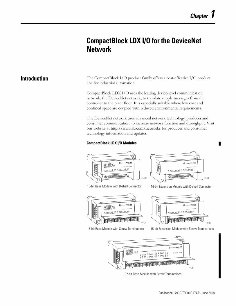
Introduction The CompactBlock I/O product family offers a cost-effective I/O product line for industrial automation.
CompactBlock LDX I/O uses the leading device-level communication network, the DeviceNet network, to translate simple messages from the controller to the plant floor. It is especially suitable where low cost and confined space are coupled with reduced environmental requirements.
The DeviceNet network uses advanced network technology, producer and consumer communication, to increase network function and throughput. Visit our website at http://www.ab.com/networks for producer and consumer technology information and updates.
CompactBlock LDX I/O Modules
1790D-8BV8VX
1790D-T8BV8VX
1790D-T32BVO
32 INPUTS - 24V DC0 1 2 3 4 5 6 7
8 9 10 11 12 13 14 15
16 17 18 19 20 21 22 23
24 25 26 27 28 29 30 31
DC INPUTS
44432
16-bit Base Module with D-shell Connector 16-bit Expansion Module with D-shell Connector
16-bit Base Module with Screw Terminations 16-bit Expansion Module with Screw Terminations
44433
44434 44435
32-bit Base Module with Screw Terminations
44364

Publication 1790D-TD001D-EN-P - June 2008
8 Chapter 1: CompactBlock LDX I/O for the DeviceNet Network
The table shows what CompactBlock LDX I/O for DeviceNet base and expansion modules are available with D-shell connectors.
CompactBlock LDX I/O Modules with D-shell Connectors
D-shell Modules Description
1790D-0B16 24V dc, 16 sourcing output base module
1790-0B16X 24V dc, 16 sourcing output expansion module
1790D-0V16 24V dc, 16 sinking output base module
1790-0V16X 24V dc, 16 sinking output expansion module
1790D-0W6 6-relay output base module
1790-0W8X 8-relay output expansion module
1790D-16BV0 24V dc, 16 universal input base module
1790-16BV0X 24V dc, 16 universal input expansion module
1790D-8BV8B 24V dc, 8 universal input/8 sourcing output base module
1790-8BV8BX 24V dc, 8 universal input/8 sourcing output expansion module
1790D-8BV8V 24V dc, 8 universal input/8 sinking output base module
1790-8BV8VX 24V dc, 8 universal input/8 sinking output expansion module
1790D-4R0 4-channel input RTD base module
1790D-4T0 4-channel input thermocouple base module
1790D-N0C2 2-channel analog output current module
1790D-N0V2 2-channel analog output voltage module
1790D-N4C0 4-channel analog input current module
1790D-N4V0 4-channel analog input voltage module

Publication 1790D-TD001D-EN-P - June 2008
Chapter 1: CompactBlock LDX I/O for the DeviceNet Network 9
The table shows what CompactBlock LDX I/O for DeviceNet base and expansion modules are available with screw terminations (terminal blocks).
CompactBlock LDX I/O Modules with Screw Terminations
Terminal Blocks Description
1790D-T0A6 120V ac, 6 output base module
1790-T0A8X 120V ac, 8 output expansion module
1790D-T0B16 24V dc, 16 sourcing output base module
1790-T0B16X 24V dc, 16 sourcing output expansion module
1790D-T0B32 24V dc, 32 sourcing output base module
1790D-T0V16 24V dc, 16 sinking output base module
1790-T0V16X 24V dc,16 sinking output expansion module
1790D-T0V32 24V dc, 32 sinking output base module
1790D-T0W6 6-relay output base module
1790-T0W8X 8-relay output expansion module
1790D-T16BV0 24V dc, 16 universal input base module
1790-T16BV0X 24V dc, 16 universal input expansion module
1790D-T32BV0 24V dc, 32 universal input base module
1790D-T8A0 120V ac, 8 input base module
1790-T8A0X 120V ac, 8 input expansion module
1790D-T8BV8B 24V dc, 8 universal input/8 sourcing output base module
1790-T8BV8BX 24V dc, 8 universal input/8 sourcing output expansion module
1790D-T16BV16B 24V dc, 16 universal input/16 sourcing output base module
1790D-T8BV8V 24V dc, 8 universal input/8 sinking output base module
1790-T8BV8VX 24V dc, 8 universal input/8 sinking output expansion module
1790D-T16BV16V 24V dc, 16 universal input/16 sinking output base module
1790D-T4R0 4-channel input RTD base module
1790D-T4T0 4-channel input thermocouple base module
1790D-TN0C2 2-channel analog current output module
1790D-TN0V2 2-channel analog voltage output module
1790D-TN4C0 4-channel analog current input module
1790D-TN4V0 4-channel analog voltage input module

Publication 1790D-TD001D-EN-P - June 2008
10 Chapter 1: CompactBlock LDX I/O for the DeviceNet Network
Features CompactBlock LDX I/O for DeviceNet modules are compatible with PLC, SLC, SoftLogix, or Logix programmable controllers by using DeviceNet scanners. All CompactBlock LDX I/O module values are accessible through the data tables of the PLC or SLC programmable controller.
Set node addresses on the modules by using rotary switches on the base module, RSNetWorx for DeviceNet software, or a similar configuration tool. Set the baud rate by using a similar configuration tool.
Benefits
• Wide breadth of I/O types can handle diverse commercial applications.• Units expand up to 4 digital modules for flexibility of node size (6…64
points).• Base modules have a built-in DeviceNet adapter.– Digital base modules (24V dc, 120V ac, and relay) support up to
three digital expansion modules.– Analog base modules (current and voltage) support up to two digital
expansion modules.– RTD and thermocouple base modules do not support expansion
modules.• Universal sink and source inputs reduce the number of components to
stock and allow flexibility of input types.• Units are compatible with a broad range of sensors that include:– NEMA/IEC Type 3 compliance for dc modules.– NEMA/IEC Type 1 compliance for ac modules.
• Very compact units can fit into confined areas - 104 x 52 x 42 mm (4 x 2 x 1.6 in.).
• Selectable termination types - removable D-shell and fixed-screw termination - are available.
• Units are easy to connect and configure by using modular EDS files.• Installation and configuration costs are minimized.• Units are ODVA conformance tested, which means there is a high level
of interoperability with other DeviceNet products.• Resistance temperature detector (RTD) and thermocouple modules
support a wide range of sensors and have on-board scaling.• Cyclic and change-of-state messaging increases network throughput and
productivity.• Auto baud rate detection is available.• Units mount horizontally or vertically on a DIN rail.• Units are UL/cUL-listed and CE-certified.

Publication 1790D-TD001D-EN-P - June 2008
Chapter 1: CompactBlock LDX I/O for the DeviceNet Network 11
Typical Configuration This illustration shows how CompactBlock LDX I/O modules fit into a typical DeviceNet system.
CompactBlock LDX I/O Modules in a DeviceNet System
System Compatibility CompactBlock LDX I/O modules are compatible with any programmable controllers when used with DeviceNet scanners.
CompactBlock LDX I/OFamily Module Communication
The CompactBlock LDX I/O modules act as slaves in a master/slave environment. I/O data is exchanged with the master through a polled, cyclic, or change-of-state connection. This selection is made in the DeviceNet scanner module’s configuration.
Polled
When the CompactBlock LDX I/O module is configured as a polled device, a master initiates communication by sending its polled I/O message to the module. The module consumes the message, updates any outputs, and produces a response. If any inputs are present, the response contains the input data.
BASE UNIT CompactBlock LDX
PULL PULL
EXPANSION UNIT CompactBlock LDX
PULL PULL
EXPANSION UNIT CompactBlock LDX
PULL PULL
1790D CompactBlock LDX I/O Modules
44412
RediSTATION Interface
1336 PLUS Drive
1305 Drive
1336 FORCE Drive
Series 9000 Photoelectric Sensors
Personal Computer with Configuration Software
DTAM Micro or DTAM Plus Module
Motor Starter with SMP-3 Overload Relay
DeviceLink I/O with Limit Switch
GV3000 Drive
FlexPac 3000 Drive
Ezlink Bearing Monitor
1784-PCD PCMCIA card
SMC Dialog Plus Module
FLEX I/O Modules
SLC Controller
DeviceView Hand-held Computer
ArmorBlock I/O Modules
PowerFlex Drive
1747-SDN Scanner1756 ControlLogix Modules
1768 CompactLogix Modules

Publication 1790D-TD001D-EN-P - June 2008
12 Chapter 1: CompactBlock LDX I/O for the DeviceNet Network
Cyclic
When using cyclic operation, the master sends data only to the CompactBlock LDX I/O module and receives data only from the module at a preconfigured time interval.
Change-of-state
When the CompactBlock LDX I/O modules are configured for change-of-state, the master sends output data only when:
• the user’s control program wants to update the module’s output.• the time period for communication has expired.
The CompactBlock LDX I/O module’s input data is sent to the master only when:
• an input changes.• the time period for communication has expired.
With change-of-state, the master does not have to request input data from the slave. It is sent automatically when data changes. In addition, an adjustable “heartbeat” is produced periodically by the CompactBlock LDX I/O module to let the consuming device know that the module connection is alive and ready to communicate.
Software and EDS File Requirements
CompactBlock LDX I/O modules require RSNetWorx for DeviceNet software, version 3.0 or later. We recommend the use of RSNetworx for DeviceNet software, version 7.0 or later. Additionally, current functions of CompactBlock LDX I/O modules require current, modular EDS files for RSNetWorx for DeviceNet software.
These files are easy to install and are available online at http://www.ab.com/networks/eds/.
EDS files for modules with matching catalog numbers (for D-shell and terminal block versions) are the same. On the website or in RSNetWorx for DeviceNet software, you can see only one catalog number listed for both versions.
Publication 1790D-TD001D-EN-P - June 2008
Chapter 1: CompactBlock LDX I/O for the DeviceNet Network 13
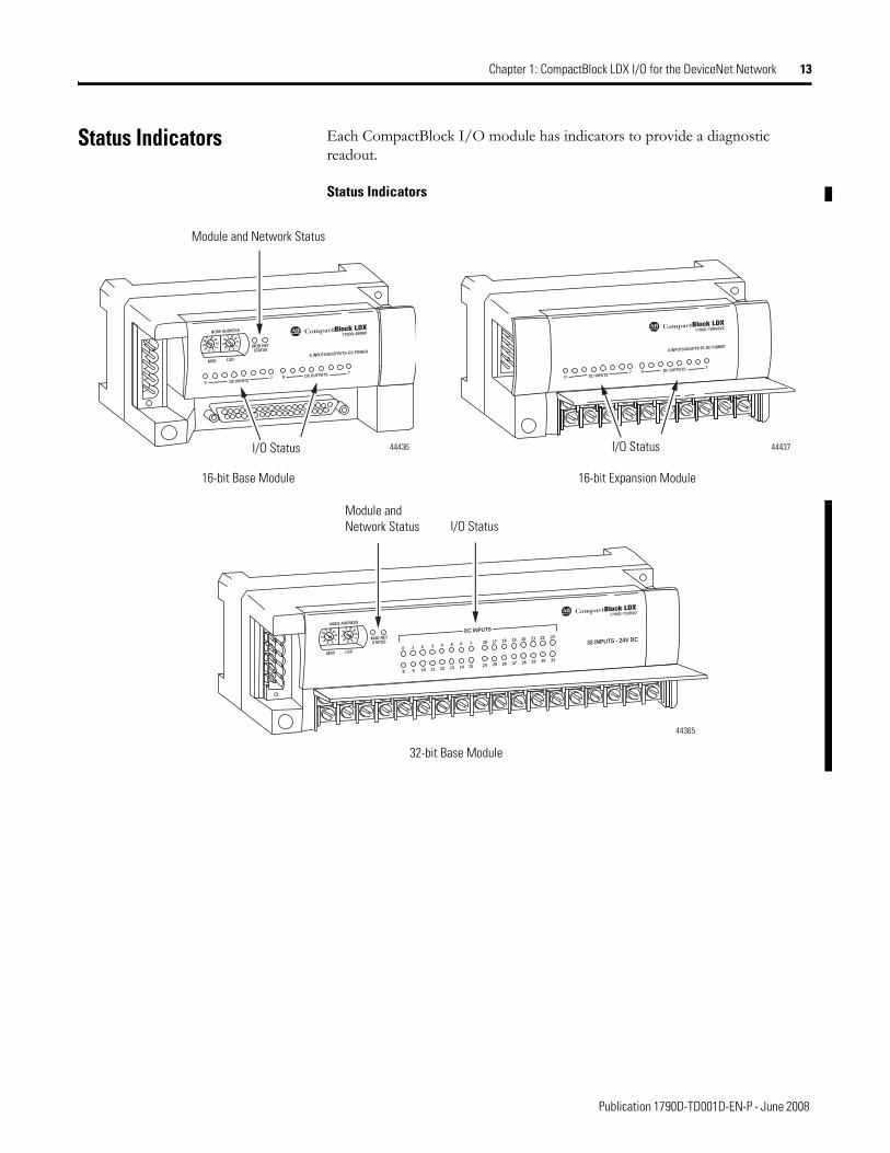
Status Indicators Each CompactBlock I/O module has indicators to provide a diagnostic readout.
Status Indicators
1790D-T8BV8VX
1790D-T32BVO
32 INPUTS - 24V DC0 1 2 3 4 5 6 7
8 9 10 11 12 13 14 15
16 17 18 19 20 21 22 23
24 25 26 27 28 29 30 31
DC INPUTS
44436 44437
Module and Network Status
I/O Status
16-bit Base Module
I/O Status
16-bit Expansion Module
32-bit Base Module
44365
Module and Network Status I/O Status

Publication 1790D-TD001D-EN-P - June 2008
14 Chapter 1: CompactBlock LDX I/O for the DeviceNet Network
Module/Network Status Indicators - All Base Modules
I/O Status Indicators - Digital Base and Expansion Modules
Indication Probable Cause Recommended Action
Module Status
Solid Red Unrecoverable fault in base unit. Replace base module.
Flashing Red Fault in expansion unit, or node address switches do not match current node address.
Reconnect or replace, as needed.
Solid Green Normal operation. None.
Off No power. Apply power to device.
Network Status
Solid Red Module node number is a duplicate of an existing node, or network communication issues exist.
Change module node number to an unused address, or verify network wiring is correct and communication is stable.
Flashing Red An I/O connection has timed out. Cycle power to the module.
Solid Green The module is operating in a normal condition, and the module is online with connections in the established state. As a group 2 module, the module is allocated to a master.
None.
Flashing Green The module is online with no connections in the established state.
Establish connections to other nodes. As a group 2 module, allocate the module to a master.
Off No power. Wait until the module has completed the dup_MAC_id test or power the module.
I/O Status Indicators
Function LED Color Module Illumination Condition
Outputs Each output Green
None.Green.
Output not energized.Output energized.
Inputs Each input Green
None.Green.
No valid input.Valid input

Publication 1790D-TD001D-EN-P - June 2008
Chapter 1: CompactBlock LDX I/O for the DeviceNet Network 15
I/O Status Indicators - Analog Base Modules
I/O Status Indicators - Analog Base Modules
1790D-NOV2, 1790D-TNOV2 Analog Voltage Output Module
1790D-NOC2, 1790D-TNOC2Analog Current Output Module
Status Description Status Description
Flashing Green/Red
Power up Flashing Green/Red
Power up
Off Offline Off Offline
Off Online and no field power Off Online and no field power
Solid Green DeviceNet connection and no field power
Green DeviceNet connection and no field power
Solid Green Field power and open wire Green Field power and open wire
Solid Green Field power and valid output Green Field power and valid output
Flashing Red Field power and output out of range
Flashing Red Field power and output out of range
Flashing Green Output idle Flashing Green Output idle
Flashing Red Recoverable fault Flashing Red Recoverable fault
1790D-N4V0, 1790D-TN4V0 1790D-N4C0, 1790D-TN4C0
Status Description Status Description
Flashing Green/Red
Power up Flashing Green/Red
Power up
Off Offline Off Offline
Solid Red Online and no field power Red Online and no field power
Solid Red DeviceNet connection and no field power
Red DeviceNet connection and no field power
Solid Green Field power and open wire
Flashing Red(1)
(1) Green for 0…20 mA range.
Field power and open wire (4…20 mA range only)(2)
(2) Can be determined from the data table.
Solid Green Field power and valid input
Green Field power and valid input
Solid Green Input over range Green Input over range
Solid Green Input under range Flashing Red(1) Input under range < 3 mA (4…20 mA range only)(2)
Flashing Red Recoverable fault Flashing Red Recoverable fault

Publication 1790D-TD001D-EN-P - June 2008
16 Chapter 1: CompactBlock LDX I/O for the DeviceNet Network
I/O Status Indicators - RTD and Thermocouple Base Modules
Power Supply Requirements
The DeviceNet network supplies power to the CompactBlock I/O base and expansion modules. Inputs and outputs are powered by an external 24V dc source that is independent of the network.
Mounting You can mount the CompactBlock I/O base and expansion modules directly to a panel or on a DIN rail. The illustration shows the base and expansion modules mounting dimensions.
1790D-4R0, 1790D-4T0
Status Description
Flashing Green/Red Power up
Off Offline
Solid Red Online and no field power
Solid Red DeviceNet connection and no field power
Flashing Red Field power and open wire
Solid Green Field power and valid input
Flashing Red Input over range
Flashing Red Input under range
Flashing Red Recoverable fault
1790D-T8BV8VX
16-point Base Module 16-point Expansion Module
41mm 1.6 in.
41mm 1.6 in.
25 mm1 in.
44438
95 mm3.74 in.
95 mm3.74 in.
1790D-T32BVO
32 INPUTS - 24V DC0 1 2 3 4 5 6 7
8 9 10 11 12 13 14 15
16 17 18 19 20 21 22 23
24 25 26 27 28 29 30 31
DC INPUTS
Expansion Cable Cover
32-point Base Module
166 mm(6.53 in.)
42.5 mm(1.67 in.)
44366

Publication 1790D-TD001D-EN-P - June 2008
Chapter 1: CompactBlock LDX I/O for the DeviceNet Network 17
Remember to consider the length of the expansion ribbon cable when installing a base module with an expansion module. The expansion module must be close enough for the expansion cable to reach from the base module to the expansion module.
Both digital and analog base modules support up to three expansion modules. Beginning with the base module, you can mount the modules either horizontally or vertically as shown in the figure.
1790D-T8BV8VX
44439
To install plug, gently pull and swing expansion cover inward.
Red strip must be on the bottom of the expansion cable.
RIGHT SIDE UP
UPSIDE DOWN
RIGHT SIDE UP
RIGHT SIDE UP RIGHT SIDE UP RIGHT SIDE UP RIGHT SIDE UP
EXPANSION UNIT CompactBlockLDX
PULL PULL
BASE UNIT CompactBlockLDX
PULL PULL
EXPANSION UNIT CompactBlockLDX
PULL PULL
EXPANSION UNIT CompactBlockLDX
PULL PULL
BASE UNIT CompactBlockLDX
PULL PULL
EXPANSION UNIT CompactBlockLDX
PULL PULL
EXPANSION UNITCompactBlockLDX
PULLPULL
Expansion Module 44416
The longer expansion cable (catalog number 1790-15CMCBL) allows up to 7 cm (2.76 in.) of space between modules.

Publication 1790D-TD001D-EN-P - June 2008
18 Chapter 1: CompactBlock LDX I/O for the DeviceNet Network
CompactBlock LDX I/O Accessories and DeviceNet Cables
This table lists the optional components for CompactBlock LDX I/O modules.
This table lists the DeviceNet cables for CompactBlock LDX I/O modules.
Optional Components for CompactBlock LDX I/O
Optional Component Catalog No.
LDX I/O replacement ribbon cable(1), 7 cm (2.76 in.), in lots of 5
(1) Included with expansion module.
1790-7CMCBL
LDX I/O longer ribbon cable, 15 cm (5.90 in.), in lots of 5 1790-15CMBL
Five-position open-style plug for the DeviceNet network 1799-DNETCON
Five-position open-style plug/locking screws for the DeviceNet network 1799-DNETSCON
DeviceNet five-position plug to five-pin micro male connector, straight, in lots of five
1799-DNC5MMS
DeviceNet Cables for CompactBlock LDX I/O
Description Lengthm (ft)
Part Number (aluminum)
Part Number (stainless steel)
Application
Mini male to conductor (unshielded)
1 (3.3) 1485-P1M5-C 1485RS-P1M5-C DeviceNet drop cable(flat media)6 (19.7) 1485R-P6M5-C 1485RS-P6M5-C
Mini male to conductor (shielded)
1 (3.3) 1485R-P1M5-C 1485P-1M5-C DeviceNet drop cable (round media)2 (6.6) 1485R-P2M5-C 1485RS-P2M5-C
3 (9.8) 1485RS-P3M5-C 1485RS-P3M5-C

19 Publication 1790D-TD001D-EN-P - June 2008
Chapter 2
DeviceNet Digital and Analog D-Shell Blocks
General Specifications The table contains specifications that are common to all of the DeviceNet base and expansion modules in this section. Individual module connection sizes, word, and bit definitions, schematics, wiring diagrams, and specifications are detailed after this table.
Environmental Specifications
Attribute Value
Operating temperature 0…55 °C (32…131 °F) for Series A0…60 °C (32…140 °F) for Series BIEC 60068-2-1 (Test Ad, Operating Cold),IEC 60068-2-2 (Test Bd, Operating Dry Heat),IEC 60068-2-14 (Test Nb, Operating Thermal Shock)
Storage temperature -40…85 °C (-40…185 °F)IEC 60068-2-1 (Test Ab, Unpackaged Nonoperating Cold),IEC 60068-2-2 (Test Bb, Unpackaged Nonoperating Dry Heat),IEC 60068-2-14 (Test Na, Unpackaged Nonoperating Thermal Shock)
Relative humidity 5…90% noncondensingIEC 60068-2-30 (Test Db, Unpackaged Nonoperating)
Operating altitude 2000 m
Vibration 5g @ 10…500 HzEC60068-2-6 (Test Fc, Operating)
Shock:operatingnonoperating
30 g IEC60068-2-27 Test Ea, (Unpackaged Shock)50 g IEC60068-2-27 Test Ea, (Unpackaged Shock)
Emissions Group 1, Class A CISPR 11
ESD immunity 8 kV air discharges IEC 61000-4-2
Radiated RF immunity 10V/m with 1 kHz sine-wave 80%AM from 80 MHz…1000 MHz10V/m with 200 Hz 50% Pulse 100%AM @ 900 MHzIEC 61000-4-3
EFT/B immunity +1 kV @ 5 kHz on power ports+2 kV @ 5 kHz on signal ports+2 kV @ 5 kHz on communications portsIEC 61000-4-4
Surge transientimmunity
+1 kV line-line (DM) and +2 kV line-earth (CM) on power ports+1 kV line-line (DM) and +2 kV line-earth (CM) on signal ports+2 kV line-earth (CM) on shielded portsIEC 61000-4-5
Conducted RF immunity 10V rms with 1 kHz sine-wave 80%AM from 150 kHz…80 MHzIEC 61000-4-6
Enclosure type rating None (open style)
Mounting DIN rail or screw
Dimensions (HxWxD), approx. 52 x 104 x 42 mm (2.03 x 4.07 x 1.64 in.)
Weight, approx. 0.3 lb (0.1 kg)

Publication 1790D-TD001D-EN-P - June 2008
20 Chapter 2: DeviceNet Digital and Analog D-Shell Blocks
Module Information This section contains detailed information for each CompactBlock LDX I/O module in these areas:
• Simplified schematic diagrams• Connection sizes• Word and bit definitions• Connection wiring diagrams• Module specifications
DeviceNet Specifications
Network protocol I/O Slave messaging:Poll command, Bit Strobe command, Cyclic command, COS command
Network length 500 m max @ 125 Kbps, 100 m max @ 500 Kbps
Indicators 1 red/green module status, 1 red/green network status
Number of nodes 64 max - rotary switch type node address setting
Communication rate 125 Kbps, 250 Kbps, 500 Kbps - auto baud rate selection
Isolation voltage 50V dc (continuous), Reinforced Insulation Type Tested at 1250V dc for 60 s, I/O to system
Wire size 0.25…2.5 mm2 (22…14 AWG) solid or stranded copper wire rated at 75 °C or greater 1.2 mm (3/64 in.) insulation max
General Specifications
Wiring category(1) 2 - on signal ports2 - on power ports2 - on communications ports
Product certifications (2)
(when product or packaging is marked)
c-UL-us UL Listed Industrial Control Equipment, certified for U.S. and Canada. See UL File E150833.
c-UL-us UL Listed for Class I, Division 2, Group A,B,C,D HazardousLocations, certified for U.S. and Canada. See UL File E195620.
European Union 89/336/EEC EMC Directive, compliant with:EN 50082-2; Industrial ImmunityEN 61326; Meas./Control/Lab., Industrial RequirementsEN 61000-6-2; Industrial ImmunityEN 61000-6-4; Industrial Emissions
European Union 73/23/EEC LVD, compliant with:EN61131-2; Programmable Controllers
C-Tick Australian Radiocommunications Act, compliant with AS/NZS CISPR11; Industrial Emissions
Open Device Vendors Association (ODVA) conformance tested to DeviceNet specifications
(1) Use this wiring category information for planning conductor routing. Refer to Industrial Automation Wiring and Grounding Guidelines, publication 1770-4.1.
(2) See the Product Certification link at http://www.ab.com for Declarations of Conformity, Certificates, and other certification details.

Publication 1790D-TD001D-EN-P - June 2008
Chapter 2: DeviceNet Digital and Analog D-Shell Blocks 21
24V dc 16 Sourcing Output Base and Expansion Modules (1790D-0B16 and 1790-0B16X)
Simplified Schematic
Connection Sizes
Word/Bit Definitions
Wiring Diagram for D-shell Connector
• Sourcing outputs - wire Com 0 and Com 2 to Field Power (+) 24V dc, wire Com 1 and Com 3 to Field Power (-) GND.Note that all Com 1 and Com 3 are internally connected.
Module Specifications
Modules I/O Points Produce (input bytes)
Consume (output bytes)
1790D-0B16 and 1790-OB16X
16 outputs 0 default1 input with status(1)
(1) Available with series B or later.
2
Input with Status Assembly Selected (1790D-0B16)Bit 07 06 05 04 03 02 01 00Produces 0 Status(1)
(1) Status indicates status of base and expansion modules, available with series B or later. There is no specific bit for Status. This byte will be used for "Status" as below:1. 00 (hex) : Normal operation2. 01 (hex) : EEPROM Checksum fault3. 02 (hex) : Too many expansion units4. 03 (hex) : EEPROM parameter not initialized or Serial Number is zero value5. 04 (hex) : First expansion unit changed6. 05 (hex) : Second expansion unit changed7. 06 (hex) : Third expansion unit changed8. 11 (hex) : Rotary S/W changed
Bit 07 06 05 04 03 02 01 00Consumes 0 O7 O6 O5 O4 O3 O2 O1 O0Consumes 1 O15 O14 O13 O12 O11 O10 O9 O8
44446
System Circuitry
Opto Isolation
Protected Output Device
Output Indication LED (logic)
Output
24V dc
GND
V dc
Word Bit DescriptionConsumes 0 00…
07Output bits - when the bit is set (1), the output will be turned on.Bit 00 corresponds to output O0, bit 01 corresponds to output 01, bit 02 to output 02, bit 03 to output 03, …
Consumes 1 08…15
Output bits - when the bit is set (1), the output will be turned on.Bit 00 corresponds to output O8, bit 01 corresponds to output O9, bit 02 to output O10, bit 03 to output O11, …
1790D-OB16 and 1790-OB16X
Attribute Value
Outputs per module 16 points nonisolated, sourcing
On-state voltage 10V dc min, 24V dc nom, 28.8V dc max
On-state voltage drop 0.5V dc max
On-state current 1 mA min per channel
Off-state voltage 28.8V dc max
Off-state leakage 0.5 mA max
Output signal delay Off to On: 0.5 ms max, On to Off: 1.0 ms max
Indicators 16 green status
Output current rating 0.5 A max per output, 4.0 A max per common
Common type 8 points/8 COM for 1790D-0B16
General Specifications
DeviceNet power - base module
Supply voltage - 24V dc nomVoltage range - 11…28.8V dcPower dissipation - 1.2 W max @ 28.8V dc
Field power Supply voltage - 24V dc nomVoltage range - 10…28.8V dcPower dissipation - 6 mA @ 28.8V dc per point
Isolation I/O to logic: photocoupler isolationIsolation voltage: 1250V ac rms
Wiring 37-pin D-shell connector
19 18 17 16 15 14 13 12 11 10 9 8 7 6 5 4 3 2 1
37 36 35 34 33 32 31 30 29 28 27 26 25 24 23 22 21 20
COM0O0
O1O2
O3O4
O5O6
O7COM2
O8O9
O10O11
O12O13
O14O15
COM1 COM1 COM1 COM1 COM1 COM3 COM3 COM3 COM3COM1 COM1 COM1 COM1 COM3 COM3 COM3 COM3 COM3
44447
Publication 1790D-TD001D-EN-P - June 2008
22 Chapter 2: DeviceNet Digital and Analog D-Shell Blocks
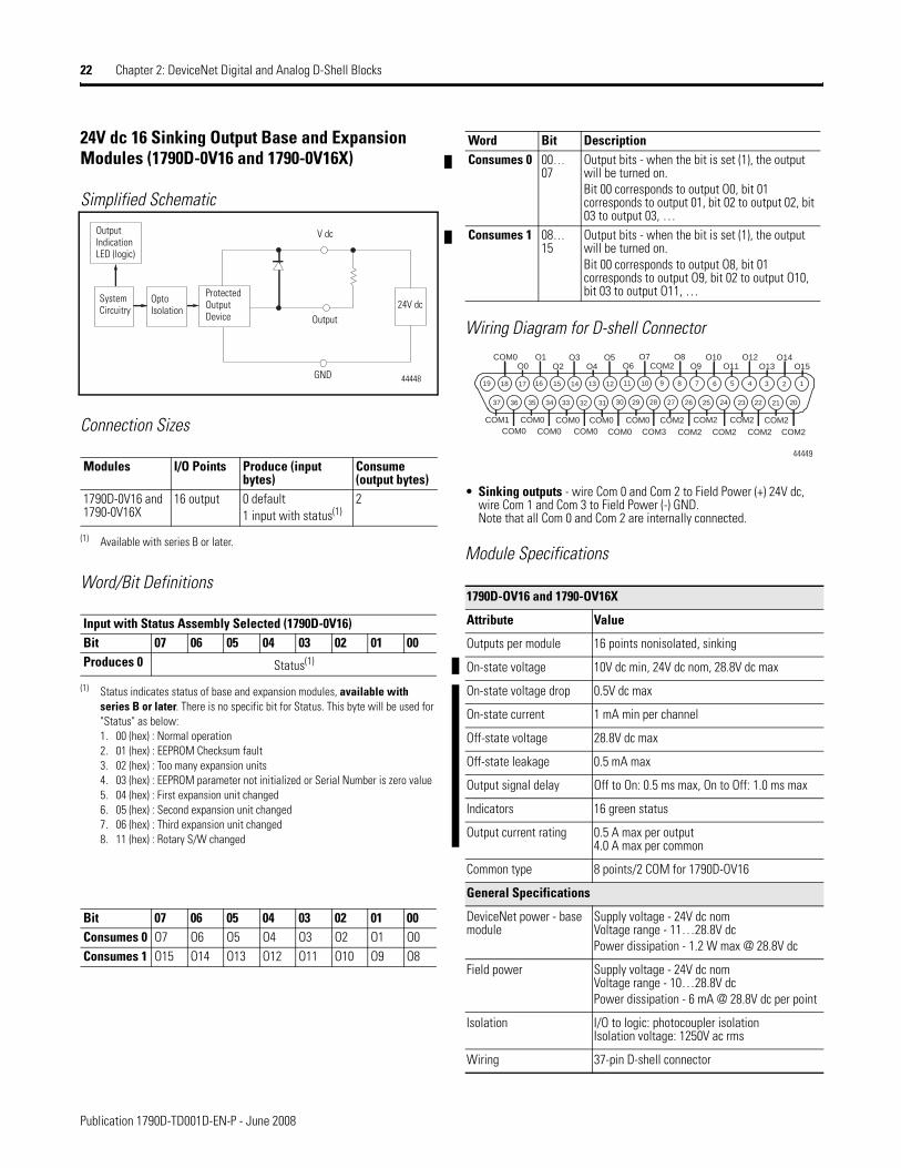
24V dc 16 Sinking Output Base and Expansion Modules (1790D-0V16 and 1790-0V16X)
Simplified Schematic
Connection Sizes
Word/Bit Definitions
Wiring Diagram for D-shell Connector
• Sinking outputs - wire Com 0 and Com 2 to Field Power (+) 24V dc, wire Com 1 and Com 3 to Field Power (-) GND.Note that all Com 0 and Com 2 are internally connected.
Module Specifications
Modules I/O Points Produce (input bytes)
Consume (output bytes)
1790D-0V16 and 1790-0V16X
16 output 0 default1 input with status(1)
(1) Available with series B or later.
2
Input with Status Assembly Selected (1790D-0V16)Bit 07 06 05 04 03 02 01 00Produces 0 Status(1)
(1) Status indicates status of base and expansion modules, available with series B or later. There is no specific bit for Status. This byte will be used for "Status" as below:1. 00 (hex) : Normal operation2. 01 (hex) : EEPROM Checksum fault3. 02 (hex) : Too many expansion units4. 03 (hex) : EEPROM parameter not initialized or Serial Number is zero value5. 04 (hex) : First expansion unit changed6. 05 (hex) : Second expansion unit changed7. 06 (hex) : Third expansion unit changed8. 11 (hex) : Rotary S/W changed
Bit 07 06 05 04 03 02 01 00Consumes 0 O7 O6 O5 O4 O3 O2 O1 O0Consumes 1 O15 O14 O13 O12 O11 O10 O9 O8
44448
System Circuitry
Opto Isolation
Protected Output Device
Output Indication LED (logic)
Output24V dc
GND
V dc
Word Bit DescriptionConsumes 0 00…
07Output bits - when the bit is set (1), the output will be turned on.Bit 00 corresponds to output O0, bit 01 corresponds to output 01, bit 02 to output 02, bit 03 to output 03, …
Consumes 1 08…15
Output bits - when the bit is set (1), the output will be turned on.Bit 00 corresponds to output O8, bit 01 corresponds to output O9, bit 02 to output O10, bit 03 to output O11, …
1790D-OV16 and 1790-OV16X
Attribute Value
Outputs per module 16 points nonisolated, sinking
On-state voltage 10V dc min, 24V dc nom, 28.8V dc max
On-state voltage drop 0.5V dc max
On-state current 1 mA min per channel
Off-state voltage 28.8V dc max
Off-state leakage 0.5 mA max
Output signal delay Off to On: 0.5 ms max, On to Off: 1.0 ms max
Indicators 16 green status
Output current rating 0.5 A max per output4.0 A max per common
Common type 8 points/2 COM for 1790D-OV16
General Specifications
DeviceNet power - base module
Supply voltage - 24V dc nomVoltage range - 11…28.8V dcPower dissipation - 1.2 W max @ 28.8V dc
Field power Supply voltage - 24V dc nomVoltage range - 10…28.8V dcPower dissipation - 6 mA @ 28.8V dc per point
Isolation I/O to logic: photocoupler isolationIsolation voltage: 1250V ac rms
Wiring 37-pin D-shell connector
19 18 17 16 15 14 13 12 11 10 9 8 7 6 5 4 3 2 1
37 36 35 34 33 32 31 30 29 28 27 26 25 24 23 22 21 20
COM0O0
O1O2
O3O4
O5O6
O7COM2
O8O9
O10O11
O12O13
O14O15
COM1 COM0 COM0 COM0 COM0 COM2 COM2 COM2 COM2COM0 COM0 COM0 COM0 COM3 COM2 COM2 COM2 COM2
44449

Publication 1790D-TD001D-EN-P - June 2008
Chapter 2: DeviceNet Digital and Analog D-Shell Blocks 23
6-relay Output Base Module (1790D-0W6)
Simplified Schematic
Connection Sizes
Word/Bit Definitions
Wiring Diagram for D-shell Connector
• Wire pins 18 and 19 to Field Power (+) 24V dc. Wire pins 36 and 37 to Field Power (-) GND.
Module Specifications
Module I/O Points Produce (input bytes)
Consume (output bytes)
1790D-0W6 6 outputs 0 default1 input with status(1)
(1) Available with series B or later.
1
Input with Status Assembly Selected (1790D-0W6)Bit 07 06 05 04 03 02 01 00Produces 0 Status(1)
(1) Status indicates status of base and expansion modules, available with series B or later. There is no specific bit for Status. This byte will be used for "Status" as below:1. 00 (hex) : Normal operation2. 01 (hex) : EEPROM Checksum fault3. 02 (hex) : Too many expansion units4. 03 (hex) : EEPROM parameter not initialized or Serial Number is zero value5. 04 (hex) : First expansion unit changed6. 05 (hex) : Second expansion unit changed7. 06 (hex) : Third expansion unit changed8. 11 (hex) : Rotary S/W changed
Bit 05 04 03 02 01 00Consumes 0 O5 O4 O3 O2 O1 O0
44450
System Circuitry
Opto Isolation
Relay
Output Indication LED (logic)
Output
24V dc
GND
V dc
Power Source
COM
Load
-
+
Word Bit DescriptionConsumes 0 00…
06Output bits - when the bit is set (1), the output will be turned on.Bit 00 corresponds to output O0, bit 01 corresponds to output 01, bit 02 to output 02, bit 03 to output 03, …
1790D-OW6
Attribute Value
Relay type Form A, normally openSingle pole, single throw
Output voltage range (load dependent)
5…28.8V dc @ 2.0 A resistive30V ac @ 2.0 A resistive
Output current rating (at rated power)
2.0 A @ 5…28.8V dc resistive2.0 A @ 30V ac resistive
Load, min 100 µA, 100 mV dc per input
On-state voltage drop, max 0.5V @ 2.0 A, resistive load, 24V dc
Initial contact resistance 30 mΩ
Expected contact life 300 Kcycles resistive, 100 Kcycles inductive
Off-state leakage, max 1.5 mA max
Output delay time Off to On: 10 ms max, On to Off: 10 ms max
Indicators 6 green status
Common type 1 point/1 COM
General Specifications
DeviceNet power Supply voltage - 24V dc nomVoltage range - 11…28.8V dcPower dissipation - 1.2 W max @ 28.8V dc
Field power Supply voltage - 24V dc nomVoltage range - 19.2…28.8V dcPower dissipation - 10 mA @ 28.8V dc per channel
Isolation I/O to logic: photocoupler isolationIsolation voltage: 1250V ac rms
Wiring 37-pin D-shell connector
19 18 17 16 15 14 13 12 11 10 9 8 7 6 5 4 3 2 1
37 36 35 34 33 32 31 30 29 28 27 26 25 24 23 22 21 20
+24V CH0COM0
CH1COM1
CH2COM2
CH3COM3
CH4COM4
CH5COM5
NCNC
NCNC
GNDGND
+24V
44451

Publication 1790D-TD001D-EN-P - June 2008
24 Chapter 2: DeviceNet Digital and Analog D-Shell Blocks
8-relay Output Expansion Module - 1790-0W8X
Simplified Schematic
Connection Sizes
Word/Bit Definitions
Wiring Diagram for D-shell Connector
• Wire pins 18 and 19 to Field Power (+) 24V dc. Wire pins 36 and 37 to Field Power (-) GND.
Module Specifications
Module I/O Points Produce (input bytes)
Consume (output bytes)
1790-0W8X 8 outputs 0 1
Bit 07 06 05 04 03 02 01 00Consumes 0 O7 O6 O5 O4 O3 O2 O1 O0
Word Bit DescriptionConsumes 0 00…
08Output bits - when the bit is set (1), the output will be turned on.Bit 00 corresponds to output O0, bit 01 corresponds to output 01, bit 02 to output 02, bit 03 to output 03, …
44450
System Circuitry
Opto Isolation
Relay
Output Indication LED (logic)
Output
24V dc
GND
V dc
Power Source
COM
Load
-
+
1790-OW8X
Attribute Value
Relay type Form A, normally openSingle pole, single throw
Output voltage range (load dependent)
5…24V dc @ 2.0 A resistive30V ac @ 2.0 A resistive
Output current rating (at rated power)
2.0 A @ 5…24V dc resistive2.0 A @ 30V dc resistive
Load, min 100 µA, 100 mV dc per input
On-state voltage drop, max 0.5V @ 2.0 A, resistive load, 24V dc
Initial contact resistance 30 mΩ
Expected contact life 300 Kcycles resistive100 Kcycles inductive
Off-state leakage, max 1.5 mA max
Output delay time Off to On: 10 ms max, On to Off: 10 ms max
Indicators 8 green status
Common type 1 point/1 COM
General Specifications
Field power Supply voltage - 24V dc nomVoltage range - 19.2…28.8V dcPower dissipation - 10 mA @ 28.8V dc per channel
Isolation I/O to logic: photocoupler isolationIsolation voltage: 1250V ac rms
Wiring 37-pin D-shell connector
19 18 17 16 15 14 13 12 11 10 9 8 7 6 5 4 3 2 1
37 36 35 34 33 32 31 30 29 28 27 26 25 24 23 22 21 20
+24V CH0COM0
CH1COM1
CH2COM2
CH3COM3
CH4COM4
CH5COM5
CH6COM6
CH7COM7
GNDGND
+24V
44452

Publication 1790D-TD001D-EN-P - June 2008
Chapter 2: DeviceNet Digital and Analog D-Shell Blocks 25
24V dc 16 Universal Input Base and Expansion Modules (1790D-16BV0 and 1790-16BV0X)
Simplified Schematic
Connection Sizes
Word/Bit Definitions
Wiring Diagram for D-shell Connector
• For inputs 0…7: Sinking inputs - wire Com 1 to Field Power (+) 24V dc, wire Com 0 to Field Power (-) GND.Sourcing inputs - wire Com 1 to Field Power (-) GND, wire Com 0 to Field Power (+) 24V dc.
• For inputs 8…15: Sinking inputs - wire Com 3 to Field Power (+) 24V dc, wire Com 2 to Field Power (-) GND.Sourcing inputs - wire Com 3 to Field Power (-) GND, wire Com 2 to Field Power (+) 24V dc.Note that all Com 1 and Com 3 are internally connected - Com 1 is used for inputs 0…7, Com 3 is used for inputs 8…15.
Modules I/O Points Produce(input bytes)
Consume(output bytes)
1790D-16BV0, 1790-16BV0X
16 input 2 default3 inputs with status(1)
(1) Available with series B or later.
0
Default (1790D-16BV0 and 1790-16BV0X)Bit 07 06 05 04 03 02 01 00Produces 0 I7 I6 I5 I4 I3 I2 I1 I0Produces 1 I15 I14 I13 I12 I11 I10 I9 I8
Word Bit DescriptionProduces 0 00…
07Input bits - when the bit is set (1), the input is on. Bit 00 corresponds to input I0, bit 01 corresponds to input I1, bit 02 corresponds to input I2, bit 03 corresponds to input I3, …
Produces 1 08…15
Input bits - when the bit is set (1), the input is on. Bit 00 corresponds to input I8, bit 01 corresponds to input I9, bit 02 corresponds to input I10, bit 03 corresponds to input I11, …
Opto Isolation
System Circuitry
Input Indication LED (logic)
Input
24V dc
COM
+/-
-/+
44440
Inputs with Status Assembly Selected (1790D-16BV0)Bit 07 06 05 04 03 02 01 00Produces 0 Status(1)
Produces 1 I15 I14 I13 I12 I11 I10 I9 I8Produces 2 I23 I22 I21 I20 I19 I18 I17 I16
(1) Status indicates status of base and expansion modules, available with series B or later. There is no specific bit for Status. This byte will be used for "Status" as below:1. 00 (hex) : Normal operation2. 01 (hex) : EEPROM Checksum fault3. 02 (hex) : Too many expansion units4. 03 (hex) : EEPROM parameter not initialized or Serial Number is zero value5. 04 (hex) : First expansion unit changed6. 05 (hex) : Second expansion unit changed7. 06 (hex) : Third expansion unit changed8. 11 (hex) : Rotary S/W changed
Word Bit DescriptionProduces 0 00…
07Status byte
Produces 1 08…15
Input bits - when the bit is set (1), the input is on. Bit 00 corresponds to input I0, bit 01 corresponds to input I1, bit 02 corresponds to input I2, bit 03 corresponds to input I3, …
Produces 2 16…23
Input bits - when the bit is set (1), the input is on. Bit 00 corresponds to input I8, bit 01 corresponds to input I9, bit 02 corresponds to input I10, bit 03 corresponds to input I11, …
19 18 17 16 15 14 13 12 11 10 9 8 7 6 5 4 3 2 1
37 36 35 34 33 32 31 30 29 28 27 26 25 24 23 22 21 20
COM0I0
I1I2
I3I4
I5I6
I7COM2
I8I9
I10I11
I12I13
I14I15
COM1 COM1 COM1 COM1 COM1 COM3 COM3 COM3 COM3COM1 COM1 COM1 COM1 COM3 COM3 COM3 COM3 COM3
44441

Publication 1790D-TD001D-EN-P - June 2008
26 Chapter 2: DeviceNet Digital and Analog D-Shell Blocks
Module Specifications
1790D-16BVO and 1790-BVOX
Attribute Value
Inputs per block 16 points, sinking or sourcing
On-state voltage 9.6V dc min, 24V dc nom, 28.8V dc max
Off-state voltage 5.0V dc max
On-state current 8 mA max per channel @ 28.8V dc
Input impedance, nom 4.8 KΩ
Indicators 16 green input status
Common type 8 points/8COM (nonpolariy)
General Specifications
DeviceNet power - base block
Supply voltage - 24V dc nomVoltage range - 11…28.8V dcPower dissipation - 1.2 W max @ 28.8V dc
Isolation I/O to logic: photocoupler isolationIsolation voltage: 1250V ac rmsDeviceNet to logic: nonisolatedDeviceNet power: nonisolated
Wiring 37-pin D-shell connector

Publication 1790D-TD001D-EN-P - June 2008
Chapter 2: DeviceNet Digital and Analog D-Shell Blocks 27
24V dc 8 Universal Input/8 Sourcing Output Base and Expansion Modules (1790D-8BV8B and 1790-8BV8BX)
Simplified Schematic
Connection Sizes
Word/Bit DefinitionsWiring Diagram for D-shell Connector
• Sinking inputs - wire Com 1 to Field Power (+) 24V dc, wire Com 0 to Field Power (-) GND.Sourcing inputs - wire Com1 to Field Power (-) GND, wire Com 0 to Field (+) 24V dc.Note that all Com 1 are internally connected.
• Sourcing outputs -wire Com 2 to Field Power (+) 24V dc,wire Com 3 to Field Power (-) GND.Note that all Com 3 are internally connected.
Modules I/O Points Produce (input bytes)
Consume (output bytes)
1790D-8BV8B, 1790-8BV8BX
8 input / 8 output
1 default2 inputs with status(1)
(1) Available with series B or later.
1
Default (1790D-8BV8B and 1790-8BV8BX)Bit 07 06 05 04 03 02 01 00Produces 0 I7 I6 I5 I4 I3 I2 I1 I0
Word Bit DescriptionProduces 0 00…
07Input bits - when the bit is set (1), the input is on. Bit 00 corresponds to input I0, bit 01 corresponds to input I1, bit 02 corresponds to input I2, bit 03 corresponds to input I3, …
Opto Isolation
System Circuitry
Input Indication LED (logic)
System Circuitry
Opto Isolation
Protected Output Device
+/-
-/+
COM
24V dc
Output Indication LED (logic)
Output
Output24V dc
GND
V dc
Input
Input
44444
Input with Status Assembly Selected (1790D-8BV8B)Bit 07 06 05 04 03 02 01 00Produces 0 Status(1)
Produces 1 I15 I14 I13 I12 I11 I10 I9 I8
(1) Status indicates status of base and expansion modules, available with series B or later. There is no specific bit for Status. This byte will be used for "Status" as below:1. 00 (hex) : Normal operation2. 01 (hex) : EEPROM Checksum fault3. 02 (hex) : Too many expansion units4. 03 (hex) : EEPROM parameter not initialized or Serial Number is zero value5. 04 (hex) : First expansion unit changed6. 05 (hex) : Second expansion unit changed7. 06 (hex) : Third expansion unit changed8. 11 (hex) : Rotary S/W changed
Word Bit DescriptionProduces 0 00…07 Status byteProduces 1 08…15 Input bits - when the bit is set (1), the input is
on. Bit 00 corresponds to input I0, bit 01 corresponds to input I1, bit 02 corresponds to input I2, bit 03 corresponds to input I3, …
Bit 07 06 05 04 03 02 01 00Consumes O7 O6 O5 O4 O3 O2 O1 O0
Word Bit DescriptionConsumes 00…
07Output bits - when the bit is set (1), the output is on.Bit 00 corresponds to output O0, bit 01 corresponds to output 01, bit 02 to output 02, bit 03 to output 03, …
19 18 17 16 15 14 13 12 11 10 9 8 7 6 5 4 3 2 1
37 36 35 34 33 32 31 30 29 28 27 26 25 24 23 22 21 20
COM0I0
I1I2
I3I4
I5I6
I7COM2
O0O1
O2O3
O4O5
O6O7
COM1 COM1 COM1 COM1 COM1 COM3 COM3 COM3 COM3COM1 COM1 COM1 COM1 COM3 COM3 COM3 COM3 COM3
44445
Publication 1790D-TD001D-EN-P - June 2008
28 Chapter 2: DeviceNet Digital and Analog D-Shell Blocks
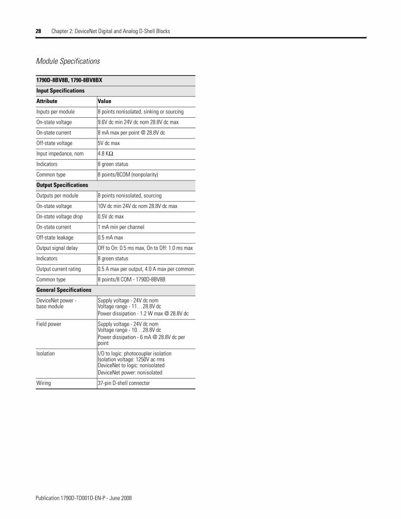
Module Specifications
1790D-8BV8B, 1790-8BV8BX
Input Specifications
Attribute Value
Inputs per module 8 points nonisolated, sinking or sourcing
On-state voltage 9.6V dc min 24V dc nom 28.8V dc max
On-state current 8 mA max per point @ 28.8V dc
Off-state voltage 5V dc max
Input impedance, nom 4.8 KΩ
Indicators 8 green status
Common type 8 points/8COM (nonpolarity)
Output Specifications
Outputs per module 8 points nonisolated, sourcing
On-state voltage 10V dc min 24V dc nom 28.8V dc max
On-state voltage drop 0.5V dc max
On-state current 1 mA min per channel
Off-state leakage 0.5 mA max
Output signal delay Off to On: 0.5 ms max, On to Off: 1.0 ms max
Indicators 8 green status
Output current rating 0.5 A max per output, 4.0 A max per common
Common type 8 points/8 COM - 1790D-8BV8B
General Specifications
DeviceNet power - base module
Supply voltage - 24V dc nomVoltage range - 11…28.8V dcPower dissipation - 1.2 W max @ 28.8V dc
Field power Supply voltage - 24V dc nomVoltage range - 10…28.8V dcPower dissipation - 6 mA @ 28.8V dc per point
Isolation I/O to logic: photocoupler isolationIsolation voltage: 1250V ac rmsDeviceNet to logic: nonisolatedDeviceNet power: nonisolated
Wiring 37-pin D-shell connector

Publication 1790D-TD001D-EN-P - June 2008
Chapter 2: DeviceNet Digital and Analog D-Shell Blocks 29
24V dc 8 Universal Input/8 Sinking Output Base and Expansion Modules (1790D-8BV8V and 1790-8BV8VX)
Simplified Schematic
Connection Sizes
Word/Bit Definitions Wiring Diagram for D-shell Connector
• Sinking inputs - wire Com 1 to Field Power (+) 24V dc, wire Com 0 to Field Power (-) GND.Sourcing inputs - wire Com1 to Field Power (-) GND, wire Com 0 to Field Power (+) 24V dc.Note that all Com 1 are internally connected.
• Sinking outputs -wire Com 2 to Field Power (+) 24V dc, wire Com 3 to Field Power (-) GND.Note that all Com 2 are internally connected.
Modules I/O Points
Produce (input bytes)
Consume (output bytes)
1790D-8BV8V, 1790-8BV8VX
8 input/8 output
1 default2 inputs with status(1)
(1) Available with series B or later.
1
Default (1790D-8BV8V and 1790-8BV8VX)Bit 07 06 05 04 03 02 01 00Produces 0 I7 I6 I5 I4 I3 I2 I1 I0
Word Bit DescriptionProduces 0 00…
07Input bits - when the bit is set (1), the input is on. Bit 00 corresponds to input I0, bit 01 corresponds to input I1, bit 02 corresponds to input I2, bit 03 corresponds to input I3, …
Opto Isolation
System Circuitry
Input Indication LED (logic)
Input
Output
Input
System Circuitry
Output
Opto Isolation
Protected Output Device
+/-
-/+
COM
24V dc
Output Indication LED (logic)
24V dc
GND
V dc
44442
Inputs with Status Assembly Selected (1790D-8BV8V)Bit 07 06 05 04 03 02 01 00Produces 0 Status(1)
Produces 1 I15 I14 I13 I12 I11 I10 I9 I8
(1) Status indicates status of base and expansion modules, available with series B or later. There is no specific bit for Status. This byte will be used for "Status" as below:1. 00 (hex) : Normal operation2. 01 (hex) : EEPROM Checksum fault3. 02 (hex) : Too many expansion units4. 03 (hex) : EEPROM parameter not initialized or Serial Number is zero value5. 04 (hex) : First expansion unit changed6. 05 (hex) : Second expansion unit changed7. 06 (hex) : Third expansion unit changed8. 11 (hex) : Rotary S/W changed
Word Bit DescriptionProduces 0 00…
07Status byte
Produces 1 08…15
Input bits - when the bit is set (1), the input is on. Bit 00 corresponds to input I0, bit 01 corresponds to input I1, bit 02 corresponds to input I2, bit 03 corresponds to input I3, …
Bit 07 06 05 04 03 02 01 00Consumes O7 O6 O5 O4 O3 O2 O1 O0
Word Bit DescriptionConsumes 00…
07Output bits - when the bit is set (1), the output is on. Bit 00 corresponds to output O0, bit 01 corresponds to output 01, bit 02 to output 02, bit 03 to output 03, …
19 18 17 16 15 14 13 12 11 10 9 8 7 6 5 4 3 2 1
37 36 35 34 33 32 31 30 29 28 27 26 25 24 23 22 21 20
COM0I0
I1I2
I3I4
I5I6
I7COM2
O0O1
O2O3
O4O5
O6O7
COM1 COM1 COM1 COM1 COM1 COM2 COM2 COM2 COM2COM1 COM1 COM1 COM1 COM3 COM2 COM2 COM2 COM2
44443

Publication 1790D-TD001D-EN-P - June 2008
30 Chapter 2: DeviceNet Digital and Analog D-Shell Blocks
Module Specifications
1790D-8BV8V and 1790-8BV8VX
Input Specifications
Attribute Value
Inputs per block 8 points nonisolated, sinking or sourcing
On-state voltage 9.6V dc min, 24V dc nom, 28.8V dc max
On-state current 8 mA max per point @ 28.8V dc
Off-state voltage 5V dc max
Input impedance, nom 4.8 KΩ
Indicators 8 green status
Common type 8 points/8COM (nonpolarity)
Output Specifications
Outputs per block 8 points nonisolated, sinking
On-state voltage 10V dc min, 24V dc nom, 28.8V dc max
On-state voltage drop 0.5V dc max
On-state current 1 mA min per channel
Off-state leakage 0.5 mA max
Output signal delay Off to On: 0.5 ms max, On to Off: 1.0 ms max
Indicators 8 green status
Output current rating 0.5 A max per output, 4.0 A max per common
Common type 8 points/8 COM
General Specifications
DeviceNet power - base block
Supply voltage - 24V dc nomVoltage range - 11…28.8V dcPower dissipation - 1.2 W max @ 28.8V dc
Field power Supply voltage - 24V dc nomVoltage range - 10…28.8V dcPower dissipation - 6 mA @ 28.8V dc per point
Isolation I/O to logic: photocoupler isolationIsolation voltage: 1250V ac rmsDeviceNet to logic: nonisolatedDeviceNet power: nonisolated
Wiring 37-pin D-shell connector

Publication 1790D-TD001D-EN-P - June 2008
Chapter 2: DeviceNet Digital and Analog D-Shell Blocks 31
4-channel Input RTD Base Module (1790D-4R0)
Simplified Schematic
Connection Sizes
Word/Bit Definitions
Input Data File
Wiring Diagram for D-shell Connector
• Wire pins 17, 18 and 19 to Field Power (+) 24V dc.Wire pins 35, 36 and 37 to Field Power (-) GND.
Module SpecificationsModule I/O Points Produce
(input bytes)Consume (output bytes)
1790D-4R0 4 channel 10 0
Word Decimal Bit Description
Read Word 0 Bits 00…15 Channel 0 input data
Read Word 1 Bits 00…15 Channel 1 input data
Read Word 2 Bits 00…15 Channel 2 input data
Read Word 3 Bits 00…15 Channel 3 input data
Read Word 4 Bits 00…03 Underrange for individual channels - Bit 00 corresponds to input channel 0, bit 01 corresponds to input channel 1 …When set (1) the input signal is below the input channel’s min range.
Bits 04…07 Not used: Set to 0
Bits 08…11 Overrange for individual channels - Bit 08 corresponds to input channel 0, bit 09 corresponds to input channel 1 and so on.When set (1) the input signal is above the input channel’s max range, or open RTD is detected.
Bits 12…15 Not used: Set to 0
Isolation
A/DMicro
controller
Network
Vcc
IndicatorLEDs
AnalogPowerSupply
Auxiliary 24VDCField Power
PowerSupply
Vcc
GND
System24VDCPower
Isolation
Transmit
Transceiver
GND
A-GND
MultiplexerA
B
Com
CH0
SENSE0
RTN0
EXC0
Input VA2
VA3
VA1EXCCurrent
VA1
Vref VrefAIN-
AIN+2
AIN+1
Channel Select
Receive
UA1UA2UA3A-GND
VDC
GND
44459
Word Bit Position15 14 13 12 11 10 9 8 7 6 5 4 3 2 1 0
0 RTD Input Data Channel 01 RTD Input Data Channel 12 RTD Input Data Channel 23 RTD Input Data Channel 34 Not Used S11 S10 S9 S8 Not Used S3 S2 S1 S0
1790D-4R0Attribute ValueInputs per module 4 channel, RTD/resistance inputInput range 1…625 ΩSensors supported
Sensor Type Degree Counts ResolutionResistance 100 mΩ1…625 Ω 10…
6250100 mΩ
Resistance 10 mΩ 1…327 Ω 100…32,700
10 mΩ
100 Ω Pt/α =0.00385
-200…850 °C -2000…8500
0.1 °C
200 Ω Pt/α =0.00385
-200…850 °C -2000…8500
0.1 °C
500 Ω Pt/α =0.00385
-200…650 °C -2000…6500
0.1 °C
100 Ω Pt/α =0.003916
-200…640 °C -2000…6400
0.1 °C
200 Ω Pt/α =0.003916
-200…640 °C -2000…6400
0.1 °C
500 Ω Pt/α =0.003916
-200…640 °C -2000… 6400
0.1 °C
100 Ω Nickel -60…250 °C -600… 2500
0.1 °C
120 Ω Nickel -80…260 °C -800… 2600
0.1 °C
200 Ω Nickel -60…250 °C -600… 2500
0.1 °C
500 Ω Nickel -60…250 °C -600… 2500
0.1 °C
19 18 17 16 15 14 13 12 11 10 9 8 7 6 5 4 3 2 1
37 36 35 34 33 32 31 30 29 28 27 26 25 24 23 22 21 20
+24V+24V
NCNC
NCCH0_A
CH0_BCH1_A
CH1_BNC
NCCH2_A
CH2_BCH3_A
CH3_BNC
NCNC
GND GND NC COM COM COM COM COM COMGND NC NC COM COM COM COM COM COM
+24V
44460

Publication 1790D-TD001D-EN-P - June 2008
32 Chapter 2: DeviceNet Digital and Analog D-Shell Blocks
Resolution 16 bits across 625 Ω, 0.1 °C/bit or 0.1 °F/bit (RTD sensors)20 bit Sigma-Delta modulation converter
Data format 16 bit integer (2’s compliment)Module scan time 8 ms/channel @ Notch Filter = 60 HzOverall accuracy 0.2% Full scale @ 0…55 °CSettable notch filter
10 Hz (default), 25 Hz, 50 Hz, 60 Hz, 100 Hz, 250 Hz, 500 Hz
Open wire detection
Out of range, open wiring
Excitation current 1 mAInput impedance 5 mΩ
DeviceNet power Supply voltage - 24V dc nomVoltage range - 11…28.8V dcPower dissipation - 1.2 W max @ 28.8V dc
Field power Supply Voltage - 24V dc nomVoltage Range - 21.6…26.4V dc (+10%)Power Dissipation - 1.5 W max @ 26.4V dc
Isolation I/O to logic: photocoupler isolationIsolation voltage: Type Test 1250V ac rms for 60 sDeviceNet to logic: nonisolatedField power: nonisolated
Indicators 4 red/green I/O statusWiring 37-pin D-shell connectorIMPORTANT: This module does not support any expansion modules.

Publication 1790D-TD001D-EN-P - June 2008
Chapter 2: DeviceNet Digital and Analog D-Shell Blocks 33
4-channel Input Thermocouple Base Module (1790D-4T0)
Simplified Schematic
Connection Sizes
Word/Bit Definitions
Input Data File
Wiring Diagram for D-shell Connector
• Wire pins 17, 18 and 19 to Field Power (+) 24V dc.Wire pins 35, 36 and 37 to Field Power (-) GND.
Module I/O Points Produce (input bytes)
Consume (output bytes)
1790D-4T0 4 channel 10 0
Word Decimal Bit
Description
Read Word 0 Bits 00…15
Channel 0 input data
Read Word 1 Bits 00…15
Channel 1 input data
Read Word 2 Bits 00…15
Channel 2 input data
Read Word 3 Bits 00…15
Channel 3 input data
Read Word 4 Bits 00…03
Underrange for individual channels - Bit 00 corresponds to input channel 0, bit 01 corresponds to input channel 1 and so on.When set (1) the input signal is below the input channel’s minimum range.
Bits 04…07
Not used: Set to 0
Bits 08…11
Overrange for individual channels - Bit 08 corresponds to input channel 0, bit 09 corresponds to input channel 1 and so on.When set (1) the input signal is above the input channel’s maximum range, or open RTD is detected.
Bits 12…15
Not used: Set to 0
A/D
A-GND
MultiplexerA
B
CH0
Input VA2
VA3
VA1
Vref VrefAIN-
AIN+
Channel Select
+
_
AnalogPowerSupply
Auxiliary 24VDCField Power
UA1UA2UA3A-GND
VDC
GNDPowerSupply
Vcc
GND
System24VDCPower
Isolation
Microcontroller
Network
Vcc
IndicatorLEDs
Isolation
Transmit
Transceiver
GND
Receive
44461
Word Bit Position15 14 13 12 11 10 9 8 7 6 5 4 3 2 1 0
0 Thermocouple Input Data Channel 01 Thermocouple Input Data Channel 12 Thermocouple Input Data Channel 23 Thermocouple Input Data Channel 34 Not Used S11 S10 S9 S8 Not Used S3 S2 S1 S0
19 18 17 16 15 14 13 12 11 10 9 8 7 6 5 4 3 2 1
37 36 35 34 33 32 31 30 29 28 27 26 25 24 23 22 21 20
+24V+24V
NCNC
NCCH0_A
CH0_BCH1_A
CH1_BNC
NCCH2_A
CH2_BCH3_A
CH3_BNC
NCNC
GND GND NC NC NC NC NC NC NCGND NC NC NC NC NC NC NC NC
+24V
44462

Publication 1790D-TD001D-EN-P - June 2008
34 Chapter 2: DeviceNet Digital and Analog D-Shell Blocks
Module Specifications
1790D-4T0Attribute ValueInputs per module 4 channel, thermocouple/mV inputInput range +76.50 mVSensors supported Sensor Type Range Scaling
Voltage 10 µV -76.50…76.50 mV -7650…7650Type B 300…1800 °C 3000…18,000Type E -270…1000 °C -2700…10,000Type J -210…1200 °C -2100…12,000Type K -270…1370 °C -2700…13,700Type R -50…1768 °C -500…17,680Type S -50…1768 °C -500…17,680Type T -270…400 °C -2700…4000Type N -270…1300 °C -2700…13,000
Resolution 16 bits, 0.1 °C/bit or 0.1°F/bit (thermocouple sensors)20 bit Sigma-Delta modulation converter
Data format 16 bit integer (2’s compliment)Module scan time 140 ms/channel @ Notch Filter = 60 HzOverall accuracy 0.2% full scale @0 °C…55 °CSettable notch filter 10 Hz (default), 25 Hz, 50 Hz, 60 Hz, 100 Hz, 250 Hz,
500 HzOpen wire detection Out of range, open wiringCold junction compensation range
0…70 °C
Input impedance 5 mΩ
General SpecificationsDeviceNet power Supply voltage - 24V dc nom
Voltage range - 11…28.8V dcPower dissipation - 1.2 W max @ 28.8V dc
Field power Supply voltage - 24V dc nomVoltage range - 21.6…26.4V dc (+10%)Power dissipation - 1.5 W max @26.4V dc
Isolation I/O to logic: photocoupler isolationIsolation voltage: Type Test 1250V ac rms for 60 sDeviceNet to logic: nonisolatedField power: nonisolated
Indicators 4 red/green I/O statusWiring 37-pin D-shell connectorIMPORTANT: This module does not support any expansion modules.

Publication 1790D-TD001D-EN-P - June 2008
Chapter 2: DeviceNet Digital and Analog D-Shell Blocks 35
2-channel Analog Current Output Module (1790D-N0C2)
Simplified Schematic
Connection Sizes
Word/Bit Definitions
Output Data File
Wiring Diagram for D-shell Connector
• Wire pins 17, 18 and 19 to Field Power (+) 24V dc.Wire pins 35, 36 and 37 to Field Power (-) GND.
Module Specifications
Module I/O Points Produce (input bytes)
Consume (output bytes)
1790D-N0C2 2 channel 0 4
Word Decimal Bit Description
Write Word 0 Bits 00…11 Channel 0 output data
Bits 12…15 Not used: Set to 0
Write Word 1 Bits 00…11 Channel 1 output data
Bits 12…15 Not used: Set to 0
Word Bit Position
15 14 13 12 11 10 9 8 7 6 5 4 3 2 1 0
0 Not Used Analog Output Data Channel 0
1 Not Used Analog Output Data Channel 1
AnalogOutput 0
AnalogOutput 1
Output 0
Output 1
Isolation
D/A
Data
Control
Microcontroller Xcur Network
Optocouplers
IndicatorLEDs
AnalogPowerSupply
AnalogPower
24VDCField
Power
PowerSupply
Vcc
GND
System24VDCPower
Isolation
44456
1790D-N0C2
Attribute Value
Outputs per module 2 channel single-ended, nonisolated
Output current 0…20 mA
Resolution 12 bits, 1/4096 max, 4.88 µA/bit
Converted data Binary data, 0000 to 0fff (max scale)
Conversion time 2ms/channel
Overall accuracy 0.2% full scale @ 0…55 °C
Calibration None required
Allowable external output load resistance
600 Ω max
Insulation resistance 20 mΩ min @ 250V dc (between insulated circuits)
General Specifications
DeviceNet power Supply voltage - 24V dc nomVoltage range - 11…28.8V dcPower dissipation - 1.2 W max @ 28.8V dc
Field power Supply voltage - 24V dc nomVoltage range - 21.6…26.4V dc (+10%)Power dissipation - 1.5 W max @26.4V dc
Isolation I/O to logic: photocoupler isolationIsolation voltage: Type Test 1250V ac rms for 60 sDeviceNet to logic: nonisolatedField power: nonisolated
Indicators 2 red/green I/O status
Wiring 37-pin D-shell connector
IMPORTANT: This analog base module can accommodate a maximum of two discrete expansion modules.
19 18 17 16 15 14 13 12 11 10 9 8 7 6 5 4 3 2 1
37 36 35 34 33 32 31 30 29 28 27 26 25 24 23 22 21 20
+24V+24V
CH0 CH1
GND GNDGND COM COM
+24V
44457

Publication 1790D-TD001D-EN-P - June 2008
36 Chapter 2: DeviceNet Digital and Analog D-Shell Blocks
2-channel Analog Voltage Output Module (1790D-N0V2)
Simplified Schematic
Connection Sizes
Word/Bit Definitions
Output Data File
Wiring Diagram for D-shell Connector
• Wire pins 17, 18 and 19 to Field Power (+) 24V dc.Wire pins 35, 36 and 37 to Field Power (-) GND.
Module Specifications
Module I/O Points Produce (input bytes)
Consume (output bytes)
1790D-N0V2 2 channel 0 4
Word Decimal Bit Description
Write Word 0 Bits 00…11 Channel 0 output data
Bits 12…15 Not used: Set to 0
Write Word 1 Bits 00…11 Channel 1 output data
Bits 12…15 Not used: Set to 0
Word Bit Position
15 14 13 12 11 10 9 8 7 6 5 4 3 2 1 0
0 Not Used Analog Output Data Channel 0
1 Not Used Analog Output Data Channel 1
AnalogOutput 0
AnalogOutput 1
Output 0
Output 1
Isolation
D/A
Data
Control
Microcontroller Xcur Network
Optocouplers
IndicatorLEDs
AnalogPowerSupply
AnalogPower
24VDCField
Power
PowerSupply
Vcc
GND
System24VDCPower
Isolation
44456
1790D-N0V2
Attribute Value
Outputs per module 2 channel single-ended, nonisolated
Output voltage 0…10V
Resolution 12 bits, 1/4096 max2.44 mV/bit
Converted data Binary data 0000 to 0fff (max scale)
Conversion time 2 ms/channel
Overall accuracy 0.2% full scale @ 0 °…55 °C
Calibration None required
Allowable external output load resistance
1 KΩ min
Output impedance 0.5 Ω max
Insulation resistance 20 mΩ min @ 250V dc (between insulated circuits)
General Specifications
DeviceNet power Supply voltage - 24V dc nomVoltage range - 11…28.8V dcPower dissipation - 1.2 W max @ 28.8V dc
Field power Supply voltage - 24V dc nomVoltage range - 21.6…26.4V dc (+10%)Power dissipation - 1.5 W max @ 26.4V dc
Isolation I/O to logic: photocoupler isolationIsolation voltage: Type Test 1250V ac rms for 60 sDeviceNet to logic: nonisolatedField power: nonisolated
Indicators 2 red/green I/O status
Wiring 37-pin D-shell connector
IMPORTANT: This analog base module can accommodate a maximum of two discrete expansion modules.
19 18 17 16 15 14 13 12 11 10 9 8 7 6 5 4 3 2 1
37 36 35 34 33 32 31 30 29 28 27 26 25 24 23 22 21 20
+24V+24V
CH0 CH1
GND GNDGND COM COM
+24V
44458

Publication 1790D-TD001D-EN-P - June 2008
Chapter 2: DeviceNet Digital and Analog D-Shell Blocks 37
4-channel Analog Current Input Module (1790D-N4C0)
Simplified Schematic
Connection Sizes
Word/Bit Definitions
Wiring Diagram for D-shell Connector
• Wire pins 17, 18 and 19 to Field Power (+) 24V dc.Wire pins 35, 36 and 37 to Field Power (-) GND.
Input Data File
Module I/O Points Produce (input bytes)
Consume (output bytes)
1790D-N4C0 4 channel 10 0
Word Decimal Bit
Description
Read Word 0
Bits 00…11
Channel 0 input data
Bits 12…15
Not used: Set to 0
Read Word 1
Bits 00…11
Channel 1 input data
Bits 12…15
Not used: Set to 0
Read Word 2
Bits 00…11
Channel 2 input data
Bits 12…15
Not used: Set to 0
AnalogInput 0
AnalogInput 1
AnalogInput 2
AnalogInput 3
Input 0
Input 1
Input 2
Input 3
Signal
Multi-plexer
Isolation
A/D
Signal
Control
Select
Microcontroller Xcur
Network
Optocouplers
IndicatorLEDs
AnalogPowerSupply
AnalogPower
24VDCField
Power
PowerSupply
Vcc
GND
System24VDCPower
Isolation
44453
Read Word 3
Bits 00…11
Channel 3 input data
Bits 12…15
Not used: Set to 0
Read Word 4
Bits 00…03
Status bits for individual channels - Bit 00 corresponds to input channel 0, bit 01 corresponds to input channel 1 and so on.When set (1) indicates:No field powerOpen wire (4…20 mA current input only)Under range (4…20 mA current input only)Recoverable module fault (whole channel to be set)Unrecoverable module fault (whole channel to be set)
Bits 04…15
Not used: Set to 0
Word Bit Position15 14 13 12 11 10 9 8 7 6 5 4 3 2 1 0
0 Not Used Analog Input Data Channel 01 Not Used Analog Input Data Channel 12 Not Used Analog Input Data Channel 23 Not Used Analog Input Data Channel 34 Not Used S3 S2 S1 S0
Word Decimal Bit
Description
19 18 17 16 15 14 13 12 11 10 9 8 7 6 5 4 3 2 1
37 36 35 34 33 32 31 30 29 28 27 26 25 24 23 22 21 20
+24V+24V
CH0 CH1 CH2 CH3
GND GNDGND COM COM COM COM
+24V
44454

Publication 1790D-TD001D-EN-P - June 2008
38 Chapter 2: DeviceNet Digital and Analog D-Shell Blocks
Module Specifications
1790D-N4C0
Attribute Value
Inputs per module 4 channel single-ended, nonisolated
Input current(software configurable)
4…20 mA (default)0…20 mA
Resolution 12 bits-unipolar, 1/4096 max3.90 µA/bit (4…20 mA)4.88 µA/bit (0…20 mA)
Converted data Binary data 0000 to 0fff (max scale)
Conversion time 10 ms/channel
Overall accuracy 0.2% full scale @ 0…55 °C
Calibration None required
Input impedance 249 ΩInsulation resistance 20 mΩ min @ 250V dc (between insulated
circuits)
General Specifications
DeviceNet power Supply voltage - 24V dc nomVoltage range - 11…28.8V dcPower dissipation - 1.2 W max @ 28.8V dc
Field power Supply voltage - 24V dc nomVoltage range - 21.6…26.4V dc (+10%)Power dissipation - 1.5 W max @ 26.4V dc
Isolation I/O to logic: photocoupler isolationIsolation voltage: Type Test 1250V ac rms for 60 sDeviceNet to logic: nonisolatedField power: nonisolated
Indicators 4 red/green I/O status
Wiring 37-pin D-shell connector
IMPORTANT: This analog base module can accommodate a maximum of two discrete expansion modules.

Publication 1790D-TD001D-EN-P - June 2008
Chapter 2: DeviceNet Digital and Analog D-Shell Blocks 39
4-channel Analog Voltage Input Module (1790D-N4V0)
Simplified Schematic
Connection Sizes
Word/Bit Definitions
Wiring Diagram for D-shell Connector
• Wire pins 17, 18 and 19 to Field Power (+) 24V dc.Wire pins 35, 36 and 37 to Field Power (-) GND.
Input Data File
Module SpecificationsModule I/O Points Produce (input bytes)
Consume (output bytes)
1790D-N4V0 4 channel 10 0
Word Decimal Bit Description
Read Word 0
Bits 00…11 Channel 0 input data
Bits 12…15 Not used: Set to 0
Read Word 1
Bits 00…11 Channel 1 input data
Bits 12…15 Not used: Set to 0
Read Word 2
Bits 00…11 Channel 2 input data
Bits 12…15 Not used: Set to 0
Read Word 3
Bits 00…11 Channel 3 input data
Bits 12…15 Not used: Set to 0
Read Word 4
Bits 00…03 Status bits for individual channels - Bit 00 corresponds to input channel 0, bit 01 corresponds to input channel 1 and so on.When set (1) indicates:No field powerOpen wire (4…20 mA current input only)Under range (4…20 mA current input only)Recoverable module fault (whole channel to be set)Unrecoverable module fault (whole channel to be set)
Bits 04…15 Not used: Set to 0
AnalogInput 0
AnalogInput 1
AnalogInput 2
AnalogInput 3
Input 0
Input 1
Input 2
Input 3
Signal
Multi-plexer
Isolation
A/D
Signal
Control
Select
Microcontroller Xcur
Network
Optocouplers
IndicatorLEDs
AnalogPowerSupply
AnalogPower
24VDCField
Power
PowerSupply
Vcc
GND
System24VDCPower
Isolation
44453
Word Bit Position15 14 13 12 11 10 9 8 7 6 5 4 3 2 1 0
0 Not Used Analog Input Data Channel 01 Not Used Analog Input Data Channel 12 Not Used Analog Input Data Channel 23 Not Used Analog Input Data Channel 34 Not Used S3 S2 S1 S0
1790D-N4V0
Attribute Value
Inputs per module 4 channel single-ended, nonisolated
Input voltage 0…10V
Resolution 12 bits-unipolar, 1/4096 max, 2.44 mV/bit
Converted data Binary data 0000 to 0fff (max scale)
Conversion time 10ms/channel
Overall accuracy 0.2% full scale @ 0…55 °C
Calibration None required
Input impedance 500 KΩ min
Insulation resistance 20 MΩ min @ 250V dc (between insulated circuits)
General Specifications
DeviceNet power Supply voltage - 24V dc nomVoltage range - 11…28.8V dcPower dissipation - 1.2 W max @ 28.8V dc
Field power Supply voltage - 24V dc nomVoltage range - 21.6…26.4V dc (+10%)Power dissipation - 1.5 W max @ 26.4V dc
Isolation I/O to logic: photocoupler isolationIsolation voltage: Type Test 1250V ac rms for 60 sDeviceNet to logic: nonisolatedField power: nonisolated
Indicators 4 red/green I/O status
Wiring 37-pin D-shell connector
IMPORTANT: This analog base module can accommodate a maximum of two discrete expansion modules.
19 18 17 16 15 14 13 12 11 10 9 8 7 6 5 4 3 2 1
37 36 35 34 33 32 31 30 29 28 27 26 25 24 23 22 21 20
+24V+24V
CH0 CH1 CH2 CH3
GND GNDGND COM COM COM COM
+24V
44455

Publication 1790D-TD001D-EN-P - June 2008
40 Chapter 2: DeviceNet Digital and Analog D-Shell Blocks
Notes:

41 Publication 1790D-TD001D-EN-P - June 2008
Chapter 3
DeviceNet Digital and Analog Terminal Blocks
General Specifications The table contains specifications that are common to all of the DeviceNet base and expansion modules in this section. Individual module connection sizes, word, and bit definitions, schematics, wiring diagrams, and specifications are detailed after this table.
Environmental Specifications
Attribute Value
Operating temperature 0…55 °C (32…131 °F) for Series A0…60 °C (32…140 °F) for Series BIEC 60068-2-1 (Test Ad, Operating Cold),IEC 60068-2-2 (Test Bd, Operating Dry Heat),IEC 60068-2-14 (Test Nb, Operating Thermal Shock)
Storage temperature -40…85 °C (-40…185 °F)IEC 60068-2-1 (Test Ab, Unpackaged Nonoperating Cold),IEC 60068-2-2 (Test Bb, Unpackaged Nonoperating Dry Heat),IEC 60068-2-14 (Test Na, Unpackaged Nonoperating Thermal Shock)
Relative humidity 5…90% noncondensingIEC 60068-2-30 (Test Db, Unpackaged Nonoperating)
Operating altitude 2000 m
Vibration 5g @ 10…500 HzEC60068-2-6 (Test Fc, Operating)
Shock:operatingnonoperating
30 g IEC60068-2-27 Test Ea, (Unpackaged Shock)50 g IEC60068-2-27 Test Ea, (Unpackaged Shock)
Emissions Group 1, Class A CISPR 11
ESD immunity 8 kV air discharges IEC 61000-4-2
Radiated RF immunity 10V/m with 1 kHz sine-wave 80%AM from 80 MHz…1000 MHz10V/m with 200 Hz 50% Pulse 100%AM @ 900 MHzIEC 61000-4-3
EFT/B immunity +1 kV @ 5 kHz on power ports+2 kV @ 5 kHz on signal ports+2 kV @ 5 kHz on communications portsIEC 61000-4-4
Surge transientimmunity
+1 kV line-line (DM) and +2 kV line-earth (CM) on power ports+1 kV line-line (DM) and +2 kV line-earth (CM) on signal ports+2 kV line-earth (CM) on shielded portsIEC 61000-4-5
Conducted RF immunity 10V rms with 1 kHz sine-wave 80%AM from 150 kHz…80 MHzIEC 61000-4-6
Enclosure type rating None (open style)
Mounting DIN rail or screw
Dimensions (HxWxD), approx. 52 x 104 x 42 mm (2.03 x 4.07 x 1.64 in.) for 16-point modules52 x 176 x 42 mm (2.03 x 6.93 x 1.64 in.) for 32-point modules
Weight, approx. 0.3 lb (0.1 kg)

Publication 1790D-TD001D-EN-P - June 2008
42 Chapter 3: DeviceNet Digital and Analog Terminal Blocks
Module Information This section contains detailed information for each CompactBlock LDX I/O module in these areas:
• Simplified schematic diagrams• Connection sizes• Word and bit definitions• Connection wiring diagrams• Module specifications
DeviceNet Specifications
Network protocol I/O Slave messaging: Poll command, Bit Strobe command, Cyclic command, COS command
Network length 500 m max @ 125 Kbps, 100 m max @ 500 Kbps
Indicators 1 red/green module status, 1 red/green network status
Number of nodes 64 max - rotary switch type node address setting
Communication rate 125 Kbps, 250 Kbps, 500 Kbps - auto baud rate selection
Isolation voltage 50V dc (continuous), Reinforced Insulation Type Tested at 1250V dc for 60 s, I/O to system
Wire size 0.25…2.5 mm2 (22…14 AWG) solid or stranded copper wire rated at 75 °C or greater 1.2 mm (3/64 in.) insulation max
General Specifications
Wiring category(1) 2 - on signal ports2 - on power ports2 - on communications ports
Product certifications (2)
(when product or packaging is marked)
c-UL-us UL Listed Industrial Control Equipment, certified for U.S. and Canada. See UL File E150833.
c-UL-us UL Listed for Class I, Division 2, Group A,B,C,D HazardousLocations, certified for U.S. and Canada. See UL File E195620.
European Union 89/336/EEC EMC Directive, compliant with:EN 50082-2; Industrial ImmunityEN 61326; Meas./Control/Lab., Industrial RequirementsEN 61000-6-2; Industrial ImmunityEN 61000-6-4; Industrial Emissions
European Union 73/23/EEC LVD, compliant with:EN61131-2; Programmable Controllers
C-Tick Australian Radiocommunications Act, compliant with AS/NZS CISPR11; Industrial Emissions
Open Device Vendors Association (ODVA) conformance tested to DeviceNet specifications
(1) Use this wiring category information for planning conductor routing. Refer to Industrial Automation Wiring and Grounding Guidelines, publication 1770-4.1.
(2) See the Product Certification link at http://www.ab.com for Declarations of Conformity, Certificates, and other certification details.

Publication 1790D-TD001D-EN-P - June 2008
Chapter 3: DeviceNet Digital and Analog Terminal Blocks 43
120V ac, 6 Output Base Module (1790D-T0A6)
Simplified Schematic
Connection Sizes
Word/Bit Definitions
Wiring Diagram for Terminal Block
• Wire 120V ac Field Power to V ac (pin 1) and COM (pin 2).Note that all V ac are internally connected. All COM are internally connected.
Module Specifications
Module I/O Points Produce (input bytes)
Consume (output bytes)
1790D-T0A6 6 outputs 0 default1 input with status(1)
(1) Available with series B or later.
1
Input with Status Assembly Selected (1790D-T0A6)Bit 07 06 05 04 03 02 01 00Produces 0 Status(1)
(1) Status indicates status of base and expansion modules, available with series B or later. There is no specific bit for Status. This byte will be used for "Status" as below:1. 00 (hex) : Normal operation2. 01 (hex) : EEPROM Checksum fault3. 02 (hex) : Too many expansion units4. 03 (hex) : EEPROM parameter not initialized or Serial Number is zero value5. 04 (hex) : First expansion unit changed6. 05 (hex) : Second expansion unit changed7. 06 (hex) : Third expansion unit changed8. 11 (hex) : Rotary S/W changed
Bit 05 04 03 02 01 00Consumes 0 O5 O4 O3 O2 O1 O0
Word Bit DescriptionConsumes 0 00…
06Output bits - when the bit is set (1), the output will be turned on.Bit 00 corresponds to output O0, bit 01 corresponds to output 01, bit 02 to output 02, bit 03 to output 03, …
44474
Output Indication LED (Logic)
System Circuitry
Opto Isolation
Output Device
OutputExternal Fuse*
Load120V ac Power
COM
COM
V ac
*1A, 250V, Normal Blow1790D-T0A6Attribute ValueOutputs per expansion module
6 points nonisolated
Load voltage range 85…132V acLoad current, max 0.5 A rmsLoad current, min 10 mA rmsOff-state leakage current, max
1.0 mA rms @ 100V rms 60 Hz
On-state voltage drop, max 1.3V rms @ max loadOperate time, max 1 msRelease, max 1/2 cycle + 1 msInsulation resistance Min 1,000 MΩ (for input-output)Dielectric strength 2500V rms 1 minute (for input-output)Indicators 6 green input statusCommon type 6 points/6 COMGeneral SpecificationsDeviceNet power Supply voltage - 24V dc nom
Voltage range - 11…28.8V dcPower dissipation - 1.2 W max @ 28.8V dc
External ac power supply Supply voltage - 110V rms, 60 HzVoltage range - 15…132V rms, 60 HzPower dissipation - 3.9 W @ rated current
Isolation I/O to logic: photocoupler isolationIsolation voltage: 1250V ac rms/V acField power: non-isolation
Wiring Terminal block (M3.0)- screw torque: 7 lb-in max (use copper or copper-clad aluminum conductors)
Recommended fusing 1 A, 250V, Normal Blow
2018161412108642
191715131197531
NCCOMCOMCOMCOMNCCOMCOMCOMCOM
NC0UT40UT20UT0VACNC0UT50UT30UT1VAC
44475

Publication 1790D-TD001D-EN-P - June 2008
44 Chapter 3: DeviceNet Digital and Analog Terminal Blocks
120V ac, 8 Output Base Module (1790-T0A8X)
Simplified Schematic
Connection Sizes
Word/Bit Definitions
Wiring Diagram for Terminal Block
• Wire 120V ac Field Power to V ac (pin 1) and COM (pin 2).Note that all V ac are internally connected. All COM are internally connected.
Module Specifications
Module I/O Points Produce (input bytes)
Consume (output bytes)
1790-T0A8X 8 outputs 0 1
Bit 07 06 05 04 03 02 01 00Consumes 0 O7 O6 O5 O4 O3 O2 O1 O0
Word Bit DescriptionConsumes 0 00…08 Output bits - when the bit is set (1), the output
will be turned on.Bit 00 corresponds to output O0, bit 01 corresponds to output 01, bit 02 to output 02, bit 03 to output 03, …
44474
Output Indication LED (Logic)
System Circuitry
Opto Isolation
Output Device
OutputExternal Fuse*
Load120V ac Power
COM
COM
V ac
*1A, 250V, Normal Blow
2018161412108642
191715131197531
COMCOMCOMCOMCOMCOMCOMCOMCOMCOM
OUT60UT40UT20UT0VACOUT70UT50UT30UT1VAC
44476
1790-T0A8XAttribute ValueOutputs per expansion module
8 points nonisolated
Load voltage range 15…132V rmsLoad current, max 0.5 A rmsLoad current, min 10 mA rmsOff-state leakage current, max
1.0 mA rms @ 100V rms 60 Hz
On-state voltage drop, max 1.3V rms @ max loadOperate time, max 1 msRelease, max 1/2 cycle + 1 msInsulation resistance Min 1,000 MΩ (for input-output)Dielectric strength 2500V rms 1 minute (for input-output)Indicators 8 green input statusCommon type 8 points/8 COMGeneral SpecificationsExternal AC power supply Supply voltage - 110V rms, 60 Hz
Voltage range - 15…132V rms, 60 HzPower dissipation - 5.2 W @ rated current
Isolation I/O to logic: photocoupler isolationIsolation voltage: 1250V ac rms/V acField power: non-isolation
Wiring Terminal block (M3.0)- screw torque: 7 lb-in max (use copper or copper-clad aluminum conductors)

Publication 1790D-TD001D-EN-P - June 2008
Chapter 3: DeviceNet Digital and Analog Terminal Blocks 45
24V dc 16 Sourcing Output Base and Expansion Modules (1790D-T0B16 and 1790-T0B16X)
Simplified Schematic
Connection Sizes
Word/Bit Definitions
Wiring Diagram for Terminal Module
• Sourcing outputs - wire V dc0 (pin 9) and V dc1 (pin 11) to Field Power (+) 24V dc, wire GND0 (pin 10) and GND1 (pin 12) to Field Power (-) GND.
Module Specifications
Modules I/O Points Produce (input bytes)
Consume (output bytes)
1790D-T0B16 and 1790-TOB16X
16 outputs 0 default1 input with status(1)
(1) Available with series B or later.
2
Input with Status Assembly Selected (1790D-T0B16)Bit 07 06 05 04 03 02 01 00Produces 0 Status(1)
(1) Status indicates status of base and expansion modules, available with series B or later. There is no specific bit for Status. This byte will be used for "Status" as below:1. 00 (hex) : Normal operation2. 01 (hex) : EEPROM Checksum fault3. 02 (hex) : Too many expansion units4. 03 (hex) : EEPROM parameter not initialized or Serial Number is zero value5. 04 (hex) : First expansion unit changed6. 05 (hex) : Second expansion unit changed7. 06 (hex) : Third expansion unit changed8. 11 (hex) : Rotary S/W changed
Bit 07 06 05 04 03 02 01 00Consumes 0 O7 O6 O5 O4 O3 O2 O1 O0Consumes 1 O15 O14 O13 O12 O11 O10 O9 O8
44446
System Circuitry
Opto Isolation
Protected Output Device
Output Indication LED (logic)
Output24V dc
GND
V dc
Word Bit DescriptionConsumes 0 00…07 Output bits - when the bit is set (1), the output
will be turned on.Bit 00 corresponds to output O0, bit 01 corresponds to output 01, bit 02 to output 02, bit 03 to output 03, …
Consumes 1 08…15 Output bits - when the bit is set (1), the output will be turned on.Bit 00 corresponds to output O8, bit 01 corresponds to output O9, bit 02 to output O10, bit 03 to output O11, …
1790D-TOB16 and 1790-TOB16XAttribute ValueOutputs per module 16 points nonisolated, sourcingOn-state voltage 10V dc min, 24V dc nom, 28.8V dc maxOn-state voltage drop 0.5V dc maxOn-state current 1 mA min per channelOff-state voltage 28.8V dc maxOff-state leakage 0.5 mA maxOutput signal delay Off to On: 0.5 ms max, On to Off: 1.0 ms maxIndicators 16 green statusOutput current rating 0.5 A max per output
4.0 A max per commonCommon type 8 points/8 COMGeneral SpecificationsDeviceNet power - base module
Supply voltage - 24V dc nomVoltage range - 11…28.8V dcPower dissipation - 1.2 W max @ 28.8V dc
Field power Supply voltage - 24V dc nomVoltage range - 10…28.8V dcPower dissipation - 6 mA @ 28.8V dc per point
Isolation I/O to logic: photocoupler isolationIsolation voltage: 1250V ac rms
Wiring Terminal block (M3.0)- screw torque: 7 lb-in max (use copper or copper-clad aluminum conductors)
2018161412108642
191715131197531
OUT15OUT11GND1OUT7OUT3OUT13OUT9GND0OUT5OUT1
OUT12OUT8VDC0OUT4OUT0OUT14OUT10VDC1OUT6OUT2
44468

Publication 1790D-TD001D-EN-P - June 2008
46 Chapter 3: DeviceNet Digital and Analog Terminal Blocks
24V dc 32 Sourcing Output Base Module (1790D-T0B32)
Simplified Schematic
Connection Sizes
Word/Bit Definitions
Wiring Diagram for Terminal Block
• Sourcing outputs - wire VDC0 (pin 1) and VDC1 (pin 19) to Field Power (+) 24V dc, wire GND0 (pin 2) and GND1 (pin 20) to Field Power (-) GND.
Modules I/O Points Produce (input bytes)
Consume (output bytes)
1790D-T0B32 32 outputs 0 default1 input with status
4
Inputs with Status Assembly Selected (1790D-T0B32)Bit 07 06 05 04 03 02 01 00Produces 0 Status(1)
(1) Status indicates status of base and expansion modules, available with series B or later. There is no specific bit for Status. This byte will be used for "Status" as below:1. 00 (hex) : Normal operation2. 01 (hex) : EEPROM Checksum fault3. 02 (hex) : Too many expansion units4. 03 (hex) : EEPROM parameter not initialized or Serial Number is zero value5. 04 (hex) : First expansion unit changed6. 05 (hex) : Second expansion unit changed7. 06 (hex) : Third expansion unit changed8. 11 (hex) : Rotary S/W changed
44446
System Circuitry
Opto Isolation
Protected Output Device
Output Indication LED (logic)
Output24V dc
GND
V dc
Bit 07 06 05 04 03 02 01 00Consumes 0 O7 O6 O5 O4 O3 O2 O1 O0Consumes 1 O15 O14 O13 O12 O11 O10 O9 O8Consumes 2 O23 O22 O21 O20 O19 O18 O17 O16Consumes 3 O31 O30 O29 O28 O27 O26 O25 O24
Word Bit DescriptionConsumes 0 00…07 Output bits - when the bit is set (1), the output
will be turned on.Bit 00 corresponds to output O0, bit 01 corresponds to output 01, bit 02 to output 02, bit 03 to output 03, …
Consumes 1 08…15 Output bits - when the bit is set (1), the output will be turned on.Bit 00 corresponds to output O8, bit 01 corresponds to output O9, bit 02 to output O10, bit 03 to output O11, …
Consumes 2 16…23 Output bits - when the bit is set (1), the output will be turned on.Bit 00 corresponds to output O16, bit 01 corresponds to output O17, bit 02 to output O18, bit 03 to output O19, …
Consumes 3 24…31 Output bits - when the bit is set (1), the output will be turned on.Bit 00 corresponds to output O24, bit 01 corresponds to output O25, bit 02 to output O26, bit 03 to output O27, …
22201816141210864
191715131197531
OUT17OUT15OUT11OUT7OUT3GND0OUT13OUT9OUT5OUT1
OUT14OUT10OUT6OUT2VDC024VOUT12OUT8OUT4OUT0
3230282624
312927252321
OUT25OUT21OUT27OUT23OUT19
OUT24OUT20OUT16OUT26OUT22OUT18
2
GND0
34
33
OUT29
OUT28
36
35
OUT31
OUT30
44483

Publication 1790D-TD001D-EN-P - June 2008
Chapter 3: DeviceNet Digital and Analog Terminal Blocks 47
Module Specifications
1790D-TOB32Attribute ValueOutputs per module 32 points nonisolated, sourcingOn-state voltage 10V dc min, 24V dc nom, 28.8V dc maxOn-state voltage drop 0.5V dc maxOn-state current 1 mA min per channelOff-state voltage 28.8V dc maxOff-state leakage 0.5 mA maxOutput signal delay Off to On: 0.5 ms max, On to Off: 1.0 ms maxIndicators 32 green statusOutput current rating 0.5 A max per output
4.0 A max per commonCommon type 16 points/2 COMGeneral SpecificationsDeviceNet power - base module
Supply voltage - 24V dc nomVoltage range - 11…28.8V dcPower dissipation - 1.2 W max @ 28.8V dc
Field power Supply voltage - 24V dc nomVoltage range - 10…28.8V dcPower dissipation - 6 mA @ 28.8V dc per point
Isolation I/O to logic: photocoupler isolationIsolation voltage: 1250V ac rms
Wiring Terminal block (M3.0)- screw torque: 7 lb-in max (use copper or copper-clad aluminum conductors)

Publication 1790D-TD001D-EN-P - June 2008
48 Chapter 3: DeviceNet Digital and Analog Terminal Blocks
24V dc 16 Sinking Output Base and Expansion Modules (1790D-T0V16 and 1790-T0V16X)
Simplified Schematic
Connection Sizes
Word/Bit Definitions
Wiring Diagram for Terminal Module
• Sinking outputs - wire V dc0 (pin 9) and V dc1 (pin 11) to Field Power (+) 24V dc, wire GND0 (pin 10) and GND1 (pin 12) to Field Power (-) GND.
Module Specifications
Modules I/O Points Produce (input bytes)
Consume (output bytes)
1790D-T0V16 and 1790-T0V16X
16 output 0 default1 input with status(1)
(1) Available with series B or later.
2
Input with Status Assembly Selected (1790D-T0V16)Bit 07 06 05 04 03 02 01 00Produces 0 Status(1)
(1) Status indicates status of base and expansion modules, available with series B or later. There is no specific bit for Status. This byte will be used for "Status" as below:1. 00 (hex) : Normal operation2. 01 (hex) : EEPROM Checksum fault3. 02 (hex) : Too many expansion units4. 03 (hex) : EEPROM parameter not initialized or Serial Number is zero value5. 04 (hex) : First expansion unit changed6. 05 (hex) : Second expansion unit changed7. 06 (hex) : Third expansion unit changed8. 11 (hex) : Rotary S/W changed
Bit 07 06 05 04 03 02 01 00Consumes 0 O7 O6 O5 O4 O3 O2 O1 O0Consumes 1 O15 O14 O13 O12 O11 O10 O9 O8
44448
System Circuitry
Opto Isolation
Protected Output Device
Output Indication LED (logic)
Output24V dc
GND
V dc
Word Bit DescriptionConsumes 0 00…
07Output bits - when the bit is set (1), the output will be turned on.Bit 00 corresponds to output O0, bit 01 corresponds to output 01, bit 02 to output 02, bit 03 to output 03, …
Consumes 1 08…15
Output bits - when the bit is set (1), the output will be turned on.Bit 00 corresponds to output O8, bit 01 corresponds to output O9, bit 02 to output O10, bit 03 to output O11, …
1790D-TOV16 and 1790-TOV16XAttribute ValueOutputs per module 16 points nonisolated, sinkingOn-state voltage 10V dc min, 24V dc nom, 28.8V dc maxOn-state voltage drop 0.5V dc maxOn-state current 1 mA min per channelOff-state voltage 28.8V dc maxOff-state leakage 0.5 mA maxOutput signal delay Off to On: 0.5 ms max, On to Off: 1.0 ms maxIndicators 16 green statusOutput current rating 0.5 A max per output
4.0 A max per common Common type 8 points/2 COMGeneral SpecificationsDeviceNet power - base module
Supply voltage - 24V dc nomVoltage range - 11…28.8V dcPower dissipation - 1.2 W max @ 28.8V dc
Field power Supply voltage - 24V dc nomVoltage range - 10…28.8V dcPower dissipation - 6 mA @ 28.8V dc per point
Isolation I/O to logic: photocoupler isolationIsolation voltage: 1250V ac rms
Wiring Terminal block (M3.0)- screw torque: 7 lb-in max (use copper or copper-clad aluminum conductors)
2018161412108642
191715131197531
OUT15OUT11GND1OUT7OUT3OUT13OUT9GND0OUT5OUT1
OUT12OUT8VDC0OUT4OUT0OUT14OUT10VDC1OUT6OUT2
44469

Publication 1790D-TD001D-EN-P - June 2008
Chapter 3: DeviceNet Digital and Analog Terminal Blocks 49
24V dc 32 Sinking Output Base Module (1790D-T0V32)
Simplified Schematic
Connection Sizes
Word/Bit Definitions
Wiring Diagram for Terminal Block
• Sinking outputs - wire VDC0 (pin 1) and VDC1 (pin 19) to Field Power (+) 24V dc, wire GND0 (pin 2) and GND1 (pin 20) to Field Power (-) GND.
Modules I/O Points Produce (input bytes)
Consume (output bytes)
1790D-T0V32 32 output 0 default1 input with status
4
Input with Status Assembly Selected (1790D-T0V32)Bit 07 06 05 04 03 02 01 00Produces 0 Status(1)
(1) Status indicates status of base and expansion modules, available with series B or later. There is no specific bit for Status. This byte will be used for "Status" as below:1. 00 (hex) : Normal operation2. 01 (hex) : EEPROM Checksum fault3. 02 (hex) : Too many expansion units4. 03 (hex) : EEPROM parameter not initialized or Serial Number is zero value5. 04 (hex) : First expansion unit changed6. 05 (hex) : Second expansion unit changed7. 06 (hex) : Third expansion unit changed8. 11 (hex) : Rotary S/W changed
Bit 07 06 05 04 03 02 01 00Consumes 0 O7 O6 O5 O4 O3 O2 O1 O0Consumes 1 O15 O14 O13 O12 O11 O10 O9 O8Consumes 2 O23 O22 O21 O20 O19 O18 O17 O16Consumes 3 O31 O30 O29 O28 O27 O26 O25 O24
44448
System Circuitry
Opto Isolation
Protected Output Device
Output Indication LED (logic)
Output24V dc
GND
V dc
Word Bit DescriptionConsumes 0 00…
07Output bits - when the bit is set (1), the output will be turned on.Bit 00 corresponds to output O0, bit 01 corresponds to output 01, bit 02 to output 02, bit 03 to output 03, …
Consumes 1 08…15
Output bits - when the bit is set (1), the output will be turned on.Bit 00 corresponds to output O8, bit 01 corresponds to output O9, bit 02 to output O10, bit 03 to output O11, …
Consumes 2 16…23
Output bits - when the bit is set (1), the output will be turned on.Bit 00 corresponds to output O16, bit 01 corresponds to output O17, bit 02 to output O18, bit 03 to output O19, …
Consumes 3 24…31
Output bits - when the bit is set (1), the output will be turned on.Bit 00 corresponds to output O24, bit 01 corresponds to output O25, bit 02 to output O26, bit 03 to output O27, …
22201816141210864
191715131197531
OUT17OUT15OUT11OUT7OUT3GND0OUT13OUT9OUT5OUT1
OUT14OUT10OUT6OUT2VDC024VOUT12OUT8OUT4OUT0
3230282624
312927252321
OUT25OUT21OUT27OUT23OUT19
OUT24OUT20OUT16OUT26OUT22OUT18
2
GND0
34
33
OUT29
OUT28
36
35
OUT31
OUT30
44483

Publication 1790D-TD001D-EN-P - June 2008
50 Chapter 3: DeviceNet Digital and Analog Terminal Blocks
Module Specifications
1790D-TOV32Attribute ValueOutputs per module 32 points nonisolated, sinkingOn-state voltage 10V dc min, 24V dc nom, 28.8V dc maxOn-state voltage drop 0.5V dc maxOn-state current 1 mA min per channelOff-state voltage 28.8V dc maxOff-state leakage 0.5 mA maxOutput signal delay Off to On: 0.5 ms max, On to Off: 1.0 ms maxIndicators 32 green statusOutput current rating 0.5 A max per output
4.0 A max per common Common type 16 points/2 COMGeneral SpecificationsDeviceNet power - base module
Supply voltage - 24V dc nomVoltage range - 11…28.8V dcPower dissipation - 1.2 W max @ 28.8V dc
Field power Supply voltage - 24V dc nomVoltage range - 10…28.8V dcPower dissipation - 6 mA @ 28.8V dc per point
Isolation I/O to logic: photocoupler isolationIsolation voltage: 1250V ac rms
Wiring Terminal block (M3.0)- screw torque: 7 lb-in max (use copper or copper-clad aluminum conductors)

Publication 1790D-TD001D-EN-P - June 2008
Chapter 3: DeviceNet Digital and Analog Terminal Blocks 51
6 Relay Output Base Module (1790D-T0W6)
Simplified Schematic
Connection Sizes
Word/Bit Definitions
Wiring Diagram for Terminal Block
• Wire V dc (pin 1) to Field Power (+) 24V dc. Wire GND (pin 2) to Field Power (-) GND.
Module Specifications
Module I/O Points Produce (input bytes)
Consume (output bytes)
1790D-T0W6 6 outputs 0 default1 input with status(1)
(1) Available with series B or later.
1
Input with Status Assembly Selected (1790D-T0W6)Bit 07 06 05 04 03 02 01 00Produces 0 Status(1)
(1) Status indicates status of base and expansion modules, available with series B or later. There is no specific bit for Status. This byte will be used for "Status" as below:1. 00 (hex) : Normal operation2. 01 (hex) : EEPROM Checksum fault3. 02 (hex) : Too many expansion units4. 03 (hex) : EEPROM parameter not initialized or Serial Number is zero value5. 04 (hex) : First expansion unit changed6. 05 (hex) : Second expansion unit changed7. 06 (hex) : Third expansion unit changed8. 11 (hex) : Rotary S/W changed
Bit 05 04 03 02 01 00Consumes 0 O5 O4 O3 O2 O1 O0
44450
System Circuitry
Opto Isolation
Relay
Output Indication LED (logic)
Output
24V dc
GND
V dc
Power Source
COM
Load
-
+
Word Bit DescriptionConsumes 0 00…06 Output bits - when the bit is set (1), the
output will be turned on.Bit 00 corresponds to output O0, bit 01 corresponds to output 01, bit 02 to output 02, bit 03 to output 03, …
1790D-TOW6Attribute ValueRelay type Form A, normally open
Single pole, single throwOutput voltage range (load dependent)
5…24V dc @ 2.0 A resistive30V ac @ 2.0 A resistive125V ac @ 2.0 A resistive250V ac @ 2.0 A resistive
Output current rating (at rated power)
2.0 A @ 5…24V dc resistive2.0 A @ 30V dc resistive
Load, min 100 µA, 100mV dc per inputOn-state voltage drop, max 0.5V @ 2.0 A, resistive load, 24V dcInitial contact resistance 30 MΩ
Expected contact life 300 Kcycles resistive100 Kcycles inductive
Off-state leakage, max 1.5 mA maxOutput delay time Off to On: 10 ms max, On to Off: 10 ms maxIndicators 6 green statusCommon type 1 point/1COMGeneral SpecificationsDeviceNet power Supply voltage - 24V dc nom
Voltage range - 11…28.8V dcPower dissipation - 1.2 W max @ 28.8V dc
Field power Supply voltage - 24V dc nomVoltage range - 19.2…28.8V dcPower dissipation - 10 mA @ 28.8V dc per channel
Isolation I/O to logic: photocoupler isolationIsolation voltage: 1250V ac rms
Wiring Terminal block (M3.0)- screw torque: 7 lb-in max (use copper or copper-clad aluminum conductors)
2018161412108642
191715131197531
NCCOM5COM3COM1NCNCCOM4COM2COM0GND
NCOUT4OUT2OUT0VDCNCOUT5OUT3OUT1NC
44470

Publication 1790D-TD001D-EN-P - June 2008
52 Chapter 3: DeviceNet Digital and Analog Terminal Blocks
8 Relay Output Expansion Module (1790-T0W8X)
Simplified Schematic
Connection Sizes
Word/Bit Definitions
Wiring Diagram for Terminal Block
• Wire V dc (pin 1) to Field Power (+) 24V dc. Wire GND (pin 2) to Field Power (-) GND.
Module Specifications
Module I/O Points Produce (input bytes)
Consume (output bytes)
1790-T0W8X 8 outputs 0 1
Bit 07 06 05 04 03 02 01 00Consumes 0 O7 O6 O5 O4 O3 O2 O1 O0
Word Bit DescriptionConsumes 0 00…08 Output bits - when the bit is set (1), the output
will be turned on.Bit 00 corresponds to output O0, bit 01 corresponds to output 01, bit 02 to output 02, bit 03 to output 03, …
44450
System Circuitry
Opto Isolation
Relay
Output Indication LED (logic)
Output
24V dc
GND
V dc
Power Source
COM
Load
-
+
2018161412108642
191715131197531
NCCOM6COM4COM2COM0COM7COM5COM3COM1GND
OUT7OUT5OUT3OUT1VDCNCOUT6OUT4OUT2OUT0
44471
1790-TOW8XAttribute ValueRelay type Form A, normally open
Single pole, single throwOutput voltage range (load dependent)
5…28V dc @ 2.0 A resistive48V ac @ 0.8 A resistive125V ac @ 2.0 A resistive250V ac @ 2.0 A resistive
Load, min 100 µA, 100mV dc per inputOn-state voltage drop, max 0.5V @ 2.0 A, resistive load, 24V dcInitial contact resistance 30 m ΩExpected contact life 300 Kcycles resistive
100 Kcycles inductiveOff-state leakage, max 1.5 mA maxOutput delay time Off to On: 10 ms max, On to Off: 10 ms maxIndicators 8 green statusCommon type 1 point/1COMGeneral SpecificationsField power Supply voltage - 24V dc nom
Voltage range - 19.2…28.8V dcPower dissipation - 2.3W @ 28.8V dc per channel
Isolation I/O to logic: photocoupler isolationIsolation voltage: 1250V ac rms
Wiring Terminal block (M3.0)- screw torque: 7 lb-in max (use copper or copper-clad aluminum conductors)

Publication 1790D-TD001D-EN-P - June 2008
Chapter 3: DeviceNet Digital and Analog Terminal Blocks 53
24V dc 16 Universal Input Base and Expansion Modules (1790D-T16BV0 and 1790-T16BV0X)
Simplified Schematic
Connection Sizes
Word/Bit Definitions
Wiring Diagram for Terminal Block
• For inputs 0…7: Sinking inputs - wire COM 0 (pin 9) to Field Power (-) GND.Sourcing inputs - wire COM 0 (pin 9) to Field Power (+) 24V dc.
• For inputs 8…15: Sinking inputs - wire COM 1 (pin 11) to Field Power (-) GND.Sourcing inputs - wire COM 1 (pin 11) to Field Power (+) 24V dcNote that both COM 0 are internally connected - COM 0 is used for inputs 0-7, COM 1 is used for inputs 8-15. Both COM 1 are internally connected.
Modules I/O Points Produce (input bytes)
Consume (output bytes)
1790D-T16BV0, 1790-T16BV0X
16 inputs 2 default3 input with status(1)
(1) Available with series B or later.
0
Default (1790D-T16BV0 and 1790-T16BV0X)Bit 07 06 05 04 03 02 01 00Produces 0 I7 I6 I5 I4 I3 I2 I1 I0Produces 1 I15 I14 I13 I12 I11 I10 I9 I8
Word Bit DescriptionProduces 0 00…07 Input Status bits - when the bit is set (1), the
input is on. Bit 00 corresponds to input I0, bit 01 corresponds to input I1, bit 02 corresponds to input I2, bit 03 corresponds to input I3, …
Produces 1 08…15 Input Status bits - when the bit is set (1), the input is on. Bit 00 corresponds to input I8, bit 01 corresponds to input I9, bit 02 corresponds to input I10, bit 03 corresponds to input I11, …
Opto Isolation
System Circuitry
Input Indication LED (logic)
Input
24V dc
COM
+/-
-/+
44440
Inputs with Status Assembly Selected (1790D-T16BV0)Bit 07 06 05 04 03 02 01 00Produces 0 Status(1)
Produces 1 I15 I14 I13 I12 I11 I10 I9 I8Produces 2 I16 I15 I14 I13 I12 I11 I10 I9
(1) Status indicates status of base and expansion modules, available with series B or later. There is no specific bit for Status. This byte will be used for "Status" as below:1. 00 (hex) : Normal operation2. 01 (hex) : EEPROM Checksum fault3. 02 (hex) : Too many expansion units4. 03 (hex) : EEPROM parameter not initialized or Serial Number is zero value5. 04 (hex) : First expansion unit changed6. 05 (hex) : Second expansion unit changed7. 06 (hex) : Third expansion unit changed8. 11 (hex) : Rotary S/W changed
Word Bit DescriptionProduces 0 00…07 Status byteProduces 0 08…15 Input Status bits - when the bit is set (1), the
input is on. Bit 00 corresponds to input I0, bit 01 corresponds to input I1, bit 02 corresponds to input I2, bit 03 corresponds to input I3, …
Produces 1 16…23 Input Status bits - when the bit is set (1), the input is on. Bit 00 corresponds to input I8, bit 01 corresponds to input I9, bit 02 corresponds to input I10, bit 03 corresponds to input I11, …
2018161412108642
191715131197531
IN15IN11COM1IN7IN3IN13IN9COM0IN5IN1
IN12IN8COM0IN4IN0IN14IN10COM1IN6IN2
44463

Publication 1790D-TD001D-EN-P - June 2008
54 Chapter 3: DeviceNet Digital and Analog Terminal Blocks
Module Specifications
1790D-T16BVO and 1790-TBV0XAttribute ValueInputs per module 16 points, sinking or sourcingOn-state voltage 9.6V dc min, 24V dc nom, 28.8V dc maxOff-state voltage 5.0V dc maxOn-state current 8 mA max per channel @ 28.8V dcInput impedance, nom 4.8 KΩ Indicators 16 green input statusCommon type 8 points/8COM (non-polarity)General SpecificationsDeviceNet power - base module
Supply voltage - 24V dc nomVoltage range - 11…28.8V dcPower dissipation - 1.2 W max @ 28.8V dc
Isolation I/O to logic: photocoupler isolationIsolation voltage: 1250V ac rmsDeviceNet to logic: nonisolatedDeviceNet power: nonisolated
Wiring Terminal block (M3.0)- screw torque: 7 lb-in max (use copper or copper-clad aluminum conductors)

Publication 1790D-TD001D-EN-P - June 2008
Chapter 3: DeviceNet Digital and Analog Terminal Blocks 55
24V dc 32 Universal Input Base Module (1790D-T32BV0)
Simplified Schematic
Connection Sizes
Word/Bit Definitions
Wiring Diagram for Terminal Block
• For inputs 0…15: Sinking inputs - wire COM0 (pin 1) to Field Power (-) GND.Sourcing inputs - wire COM0 (pin 1) to Field Power (+) 24V dc.Note that both COM0 (pins 1 and 2) are internally connected.
Modules I/O Points Produce (input bytes)
Consume (output bytes)
1790D-T32BV0 32 inputs 4 default5 inputs with status
0
Default (1790D-T32BV0)Bit 07 06 05 04 03 02 01 00Produces 0 I7 I6 I5 I4 I3 I2 I1 I0Produces 1 I15 I14 I13 I12 I11 I10 I9 I8Produces 2 I23 I22 I21 I20 I19 I18 I17 I16Produces 3 I31 I30 I29 I28 I27 I26 I25 I24
Word Bit DescriptionProduces 0 00…07 Input Status bits - when the bit is set (1), the
input is on. Bit 00 corresponds to input I0, bit 01 corresponds to input I1, bit 02 corresponds to input I2, bit 03 corresponds to input I3, …
Produces 1 08…15 Input Status bits - when the bit is set (1), the input is on. Bit 00 corresponds to input I8, bit 01 corresponds to input I9, bit 02 corresponds to input I10, bit 03 corresponds to input I11, …
Produces 2 16…23 Input Status bits - when the bit is set (1), the input is on. Bit 00 corresponds to input I16, bit 01 corresponds to input I17, bit 02 corresponds to input I18, bit 03 corresponds to input I19, …
Produces 3 24…31 Input Status bits - when the bit is set (1), the input is on. Bit 00 corresponds to input I24, bit 01 corresponds to input I25, bit 02 corresponds to input I26, bit 03 corresponds to input I27, …
Opto Isolation
System Circuitry
Input Indication LED (logic)
Input
24V dc
COM
+/-
-/+
44440
Inputs with Status Assembly Selected (1790D-T32BV0)Bit 07 06 05 04 03 02 01 00Produces 0 Status(1)
Produces 1 I15 I14 I13 I12 I11 I10 I9 I8Produces 2 I23 I22 I21 I20 I19 I18 I17 I16Produces 3 I31 I30 I29 I28 I27 I26 I25 I24Produces 4 I39 I38 I37 I36 I35 I34 I33 I32
(1) Status indicates status of base and expansion modules, available with series B or later. There is no specific bit for Status. This byte will be used for "Status" as below:1. 00 (hex) : Normal operation2. 01 (hex) : EEPROM Checksum fault3. 02 (hex) : Too many expansion units4. 03 (hex) : EEPROM parameter not initialized or Serial Number is zero value5. 04 (hex) : First expansion unit changed6. 05 (hex) : Second expansion unit changed7. 06 (hex) : Third expansion unit changed8. 11 (hex) : Rotary S/W changed
Word Bit DescriptionProduces 0 00…07 Status byteProduces 1 08…15 Input Status bits - when the bit is set (1), the
input is on. Bit 00 corresponds to input I0, bit 01 corresponds to input I1, bit 02 corresponds to input I2, bit 03 corresponds to input I3, …
Produces 2 16…23 Input Status bits - when the bit is set (1), the input is on. Bit 00 corresponds to input I8, bit 01 corresponds to input I9, bit 02 corresponds to input I10, bit 03 corresponds to input I11, …
Produces 3 24…31 Input Status bits - when the bit is set (1), the input is on. Bit 00 corresponds to input I16, bit 01 corresponds to input I17, bit 02 corresponds to input I18, bit 03 corresponds to input I19, …
Produces 4 32…39 Input Status bits - when the bit is set (1), the input is on. Bit 00 corresponds to input I24, bit 01 corresponds to input I25, bit 02 corresponds to input I26, bit 03 corresponds to input I27, …
22201816141210864
191715131197531
IN17IN15IN11IN7IN3COM1IN13IN9IN5IN1
IN14IN10IN6IN2COM0COM1IN12IN8IN4IN0
3230282624
312927252321
IN25IN21IN27IN23IN19
IN24IN20IN16IN26IN22IN18
2
COM0
34
33
IN29
IN28
36
35
IN31
IN30
44464

Publication 1790D-TD001D-EN-P - June 2008
56 Chapter 3: DeviceNet Digital and Analog Terminal Blocks
• For inputs 16…31: Sinking inputs - wire COM1 (pin 19) to Field Power (-) GND.Sourcing inputs - wire COM1 (pin 19) to Field Power (+) 24V dc.Note that both COM1 (pins 19 and 20) are internally connected.
Module Specifications
1790D-T32BV0Attribute ValueInputs per module 32 points, sinking or sourcingOn-state voltage 9.6V dc min, 24V dc nom, 28.8V dc maxOff-state voltage 5.0V dc maxOn-state current 8 mA max per channel @ 28.8V dcInput impedance, nom 4.8 KΩIndicators 32 green input statusCommon type 16 points/4COM (non-polarity)General SpecificationsDeviceNet power - base module
Supply voltage - 24V dc nomVoltage range - 11…28.8V dcPower dissipation - 1.2 W max @ 28.8V dc
Isolation I/O to logic: photocoupler isolationIsolation voltage: 1250V ac rmsDeviceNet to logic: nonisolatedDeviceNet power: nonisolated
Wiring Terminal block (M3.0)- screw torque: 7 lb-in max (use copper or copper-clad aluminum conductors)

Publication 1790D-TD001D-EN-P - June 2008
Chapter 3: DeviceNet Digital and Analog Terminal Blocks 57
120V ac 8 Input Base and Expansion Modules (1790D-T8A0 and 1790-T8A0X)
Simplified Schematic
Connection Sizes
Word/Bit Definitions
Wiring Diagram for Terminal Block
• Wire 120V ac Field Power to V ac (pin 1) and COM (pin 2).Note that all V ac are internally connected. All COM are internally connected.
Modules I/O Points Produce (input bytes)
Consume (output bytes)
1790D-T8A0 and 1790-T8A0X
8 inputs 1 default2 inputs with status(1)
(1) Available with series B or later.
0
Default (1790D-T8A0 and 1790-T8A0X)Bit 07 06 05 04 03 02 01 00Produces 0 I7 I6 I5 I4 I3 I2 I1 I0
Word Bit DescriptionProduces 0 00…07 Input bits - when the bit is set (1), the
input will be turned on. Bit 00 corresponds to input I0, bit 01 corresponds to input I1, bit 02 to input I2, bit 03 to input I3, …
44472
Opto Isolation
System Circuitry
Input Indication LED (logic)Input
Device
Input
120V ac Power
V ac
COM
COM
Inputs with Status Assembly Selected (1790D-T8A0, 1790-T8A0X)Bit 07 06 05 04 03 02 01 00Produces 0 Status(1)
Produces 1 I15 I14 I13 I12 I11 I10 I9 I8
(1) Status indicates status of base and expansion modules, available with series B or later. There is no specific bit for Status. This byte will be used for "Status" as below:1. 00 (hex) : Normal operation2. 01 (hex) : EEPROM Checksum fault3. 02 (hex) : Too many expansion units4. 03 (hex) : EEPROM parameter not initialized or Serial Number is zero value5. 04 (hex) : First expansion unit changed6. 05 (hex) : Second expansion unit changed7. 06 (hex) : Third expansion unit changed8. 11 (hex) : Rotary S/W changed
Word Bit DescriptionProduces 0 00…07 Status byteProduces 1 08…15 Input bits - when the bit is set (1), the input
will be turned on. Bit 00 corresponds to input I0, bit 01 corresponds to input I1, bit 02 to input I2, bit 03 to input I3, …
2018161412108642
191715131197531
COMCOMCOMCOMCOMCOMCOMCOMCOMCOM
IN6IN4IN2IN0VACIN7IN5IN3IN1VAC
44473

Publication 1790D-TD001D-EN-P - June 2008
58 Chapter 3: DeviceNet Digital and Analog Terminal Blocks
Module Specifications
1790D-T8AO and 1790-T8A0XAttribute ValueInputs per module 8 points nonisolatedOn-state voltage range 85V ac min
110V ac nom132V ac max
Input impedance 18 kΩ
On-state current 9 mA max @ 132V acOff-state voltage 45V ac maxInput signal delay Off to On: 10 ms, On to Off: 30 msIndicators 8 green input statusCommon type 8 points/8 COMGeneral SpecificationsDeviceNet power - base module
Supply voltage - 24V dc nomVoltage range - 11…28.8V dcPower dissipation - 1.2 W max @ 28.8V dc
External AC power supply Supply voltage - 110V rms, 60 HzVoltage range - 85…32V rms, 47…63 HzPower dissipation - 3 W @ 132V ac
Isolation I/O to logic: photocoupler isolationIsolation voltage: 1250V ac rms/V acField power: non-isolation
Wiring Terminal block (M3.0)- screw torque: 7 lb-in max (use copper or copper-clad aluminum conductors)
Recommended fusing 1 A, 250V, normal blow

Publication 1790D-TD001D-EN-P - June 2008
Chapter 3: DeviceNet Digital and Analog Terminal Blocks 59
24V dc 8 Universal Input/8 Sourcing Output Base and Expansion Modules (1790D-T8BV8B and 1790-T8BV8BX)
Simplified Schematic
Connection Sizes
Word/Bit DefinitionsWiring Diagram for Terminal Block
• Sinking inputs - wire COM (pin 9) to Field Power (-) GND.Sourcing inputs - wire COM (pin 9) to Field Power (+) 24V dc.Note that both COM (pins 9 and 10) are internally connected.
• Sourcing outputs -wire V dc (pin 11) to Field Power (+) 24V dc,wire GND (pin 12) to Field Power (-) GND.
Modules I/O Points
Produce (input bytes)
Consume (output bytes)
1790D-T8BV8B, 1790-T8BV8BX
8 input / 8 output
1 default2 inputs with status(1)
(1) Available with series B or later.
1
Default (1790D-T8BV8B and 1790-T8BV8BX)Bit 07 06 05 04 03 02 01 00Produces 0 I7 I6 I5 I4 I3 I2 I1 I0
Word Bit DescriptionProduces 0 00…07 Input Status bits - when the bit is set (1), the
input is on. Bit 00 corresponds to input I0, bit 01 corresponds to input I1, bit 02 corresponds to input I2, bit 03 corresponds to input I3, …
Opto Isolation
System Circuitry
Input Indication LED (logic)
System Circuitry
Opto Isolation
Protected Output Device
+/-
-/+
COM
24V dc
Output Indication LED (logic)
Output
Output24V dc
GND
V dc
Input
Input
44444
Inputs with Status Assembly Selected (1790D-T8BV8B)Bit 07 06 05 04 03 02 01 00Produces 0 Status(1)
Produces 1 I15 I14 I13 I12 I11 I10 I9 I8
(1) Status indicates status of base and expansion modules, available with series B or later. There is no specific bit for Status. This byte will be used for "Status" as below:1. 00 (hex) : Normal operation2. 01 (hex) : EEPROM Checksum fault3. 02 (hex) : Too many expansion units4. 03 (hex) : EEPROM parameter not initialized or Serial Number is zero value5. 04 (hex) : First expansion unit changed6. 05 (hex) : Second expansion unit changed7. 06 (hex) : Third expansion unit changed8. 11 (hex) : Rotary S/W changed
Word Bit DescriptionProduces 0 00…07 Status byteProduces 1 08…15 Input Status bits - when the bit is set (1), the
input is on. Bit 00 corresponds to input I0, bit 01 corresponds to input I1, bit 02 corresponds to input I2, bit 03 corresponds to input I3, …
Bit 07 06 05 04 03 02 01 00Consumes O7 O6 O5 O4 O3 O2 O1 O0
Word Bit DescriptionConsumes 00…07 Output bits - when the bit is set (1), the output
is on.Bit 00 corresponds to output O0, bit 01 corresponds to output 01, bit 02 to output 02, bit 03 to output 03, …
2018161412108642
191715131197531
OUT7OUT3GNDIN7IN3OUT5OUT1COMIN5IN1
OUT4OUT0COMIN4IN0OUT6OUT2VDCIN6IN2
44467

Publication 1790D-TD001D-EN-P - June 2008
60 Chapter 3: DeviceNet Digital and Analog Terminal Blocks
Module Specifications
1790D-T8BV8B, 1790-T8BV8BXInput SpecificationsAttribute ValueInputs per module 8 points nonisolated, sinking or sourcingOn-state voltage 9.6V dc min 24V dc nom 28.8V dc maxOn-state current 8 mA max per point @ 28.8V dcOff-state voltage 5V dc maxInput impedance, nom 4.8 KΩIndicators 8 green statusCommon type 8 points/8COM (non-polarity)Output SpecificationsOutputs per module 8 points nonisolated, sourcingOn-state voltage 10V dc min 24V dc nom 28.8V dc maxOn-state voltage drop 0.5V dc maxOn-state current 1 mA min per channelOff-state leakage 0.5 mA maxOutput signal delay Off to On: 0.5 ms max, On to Off: 1.0 ms maxIndicators 8 green statusOutput current rating 0.5 A max per output, 4.0 A max per commonCommon type 8 points/8COM (1790D-8BV8B)General SpecificationsDeviceNet power - base module
Supply voltage - 24V dc nomVoltage range - 11…28.8V dcPower dissipation - 1.2 W max @ 28.8V dc
Field power Supply voltage - 24V dc nomVoltage range - 10…28.8V dcPower dissipation - 6 mA @ 28.8V dc per point
Isolation I/O to logic: photocoupler isolationIsolation voltage: 1250V ac rmsDeviceNet to logic: nonisolatedDeviceNet power: nonisolated
Wiring Terminal block (M3.0)- screw torque: 7 lb-in max (use copper or copper-clad aluminum conductors)

Publication 1790D-TD001D-EN-P - June 2008
Chapter 3: DeviceNet Digital and Analog Terminal Blocks 61
24V dc 16 Universal Input/16 Sourcing Output Base Module (1790D-T16BV16B)
Simplified Schematic
Connection Sizes
Word/Bit Definitions
Modules I/O Points Produce (input bytes)
Consume (output bytes)
1790D-T16BV16B 16 inputs/16 outputs
2 default3 inputs with status(1)
(1) Available with series B or later.
2
Default (1790D-T16BV16B)Bit 07 06 05 04 03 02 01 00Produces 0 I7 I6 I5 I4 I3 I2 I1 I0Produces 1 I15 I14 I13 I12 I11 I10 I9 I8
Word Bit DescriptionProduces 0 00…07 Input Status bits - when the bit is set (1), the
input is on. Bit 00 corresponds to input I0, bit 01 corresponds to input I1, bit 02 corresponds to input I2, bit 03 corresponds to input I3, …
Produces 1 08…15 Input Status bits - when the bit is set (1), the input is on. Bit 00 corresponds to input I8, bit 01 corresponds to input I9, bit 02 corresponds to input I10, bit 03 corresponds to input I11, …
Opto Isolation
System Circuitry
Input Indication LED (logic)
System Circuitry
Opto Isolation
Protected Output Device
+/-
-/+
COM
24V dc
Output Indication LED (logic)
Output
Output24V dc
GND
V dc
Input
Input
44444
Inputs with Status Assembly Selected (1790D-T16BV16B)Bit 07 06 05 04 03 02 01 00Produces 0 Status(1)
Produces 1 I15 I14 I13 I12 I11 I10 I9 I8Produces 2 I23 I22 I21 I20 I19 I18 I17 I16
(1) Status indicates status of base and expansion modules, available with series B or later. There is no specific bit for Status. This byte will be used for "Status" as below:1. 00 (hex) : Normal operation2. 01 (hex) : EEPROM Checksum fault3. 02 (hex) : Too many expansion units4. 03 (hex) : EEPROM parameter not initialized or Serial Number is zero value5. 04 (hex) : First expansion unit changed6. 05 (hex) : Second expansion unit changed7. 06 (hex) : Third expansion unit changed8. 11 (hex) : Rotary S/W changed
Word Bit DescriptionProduces 0 00…07 Status byteProduces 1 08…15 Input Status bits - when the bit is set (1), the
input is on. Bit 00 corresponds to input I0, bit 01 corresponds to input I1, bit 02 corresponds to input I2, bit 03 corresponds to input I3, …
Produces 2 16…23 Input Status bits - when the bit is set (1), the input is on. Bit 00 corresponds to input I8, bit 01 corresponds to input I9, bit 02 corresponds to input I10, bit 03 corresponds to input I11, …
Bit 07 06 05 04 03 02 01 00Consumes 0 O7 O6 O5 O4 O3 O2 O1 O0Consumes 1 O15 O14 O13 O12 O11 O10 O9 O8
Word Bit DescriptionConsumes 0 00…07 Output bits - when the bit is set (1), the output
is on.Bit 00 corresponds to output O0, bit 01 corresponds to output O1, bit 02 to output O2, bit 03 to output O3, …
Consumes 1 08…15 Output bits - when the bit is set (1), the output is on.Bit 00 corresponds to output O8, bit 01 corresponds to output O9, bit 02 to output O10, bit 03 to output O11, …

Publication 1790D-TD001D-EN-P - June 2008
62 Chapter 3: DeviceNet Digital and Analog Terminal Blocks
Wiring Diagram for Terminal Block
• Sinking inputs - wire COM (pin 1) to Field Power (-) GND.Sourcing inputs - wire COM (pin 1) to Field Power (+) 24V dc.Note that both COM (pins 1 and 2) are internally connected.
• Sourcing outputs -wire V dc (pin 19) to Field Power (+) 24V dc,wire GND (pin 20) to Field Power (-) GND.
Module Specifications
22201816141210864
191715131197531
OUT1IN15IN11IN7IN3GNDIN13IN9IN5IN1
IN14IN10IN6IN2COM0VDCIN12IN8IN4IN0
3230282624
312927252321
OUT9OUT5OUT11OUT7OUT3
OUT8OUT4OUT0OUT10OUT6OUT2
2
COM0
34
33
OUT13
OUT12
36
35
OUT15
OUT14
44466
1790D-T16BV16BInput SpecificationsAttribute ValueInputs per module 16 points nonisolated, sinking or sourcingOn-state voltage 9.6V dc min 24V dc nom 28.8V dc maxOn-state current 8 mA max per point @ 28.8V dcOff-state voltage 5V dc maxInput impedance, nom 4.8 KΩIndicators 16 green statusCommon type 16 points/16COM (non-polarity)Output SpecificationsOutputs per module 16 points nonisolated, sourcingOn-state voltage 10V dc min 24V dc nom 28.8V dc maxOn-state voltage drop 0.5V dc maxOn-state current 1 mA min per channelOff-state leakage 0.5 mA maxOutput signal delay Off to On: 0.5 ms max, On to Off: 1.0 ms maxIndicators 16 green statusOutput current rating 0.5 A max per output, 4.0 A max per commonCommon type 16 points/16COMGeneral SpecificationsDeviceNet power - base module
Supply voltage - 24V dc nomVoltage range - 11…28.8V dcPower dissipation - 1.2 W max @ 28.8V dc
Field power Supply voltage - 24V dc nomVoltage range - 10…28.8V dcPower dissipation - 6 mA @ 28.8V dc per point
Isolation I/O to logic: photocoupler isolationIsolation voltage: 1250V ac rmsDeviceNet to logic: nonisolatedDeviceNet power: nonisolated
Wiring Terminal block (M3.0)- screw torque: 7 lb-in max (use copper or copper-clad aluminum conductors)

Publication 1790D-TD001D-EN-P - June 2008
Chapter 3: DeviceNet Digital and Analog Terminal Blocks 63
24V dc 8 Universal Input/8 Sinking Output Base and Expansion Modules (1790D-T8BV8V and 1790-T8BV8VX)
Simplified Schematic
Connection Sizes
Word/Bit Definitions
Wiring Diagram for Terminal Block
• Sinking inputs - wire COM (pin 9) to Field Power (-) GND.Sourcing inputs - wire COM (pin 9) to Field Power (+) 24V dc.Note that both COM (pins 9 and 10) are internally connected.
• Sinking outputs -wire V dc (pin 11) to Field Power (+) 24V dc, wire GND (pin 12) to Field Power (-) GND.
Modules I/O Points
Produce (input bytes)
Consume (output bytes)
1790D-T8BV8V and 1790-T8BV8VX
8 input / 8 output
1 default2 inputs with status(1)
(1) Available with series B or later.
1
Default (1790D-T8BV8V and 1790-T8BV8VX)Bit 07 06 05 04 03 02 01 00Produces 0 I7 I6 I5 I4 I3 I2 I1 I0
Word Bit DescriptionProduces 0 00…
07Input Status bits - when the bit is set (1), the input is on. Bit 00 corresponds to input I0, bit 01 corresponds to input I1, bit 02 corresponds to input I2, bit 03 corresponds to input I3, …
Opto Isolation
System Circuitry
Input Indication LED (logic)
Input
Output
Input
System Circuitry
Output
Opto Isolation
Protected Output Device
+/-
-/+
COM
24V dc
Output Indication LED (logic)
24V dc
GND
V dc
44442
Inputs with Status Assembly Selected (1790D-T8BV8V)Bit 07 06 05 04 03 02 01 00Produces 0 Status(1)
Produces 1 I15 I14 I13 I12 I11 I10 I9 I8
(1) Status indicates status of base and expansion modules, available with series B or later. There is no specific bit for Status. This byte will be used for "Status" as below:1. 00 (hex) : Normal operation2. 01 (hex) : EEPROM Checksum fault3. 02 (hex) : Too many expansion units4. 03 (hex) : EEPROM parameter not initialized or Serial Number is zero value5. 04 (hex) : First expansion unit changed6. 05 (hex) : Second expansion unit changed7. 06 (hex) : Third expansion unit changed8. 11 (hex) : Rotary S/W changed
Word Bit DescriptionProduces 0 00…07 Status byteProduces 1 08…15 Input Status bits - when the bit is set (1), the
input is on. Bit 00 corresponds to input I0, bit 01 corresponds to input I1, bit 02 corresponds to input I2, bit 03 corresponds to input I3, …
Bit 07 06 05 04 03 02 01 00Consumes O7 O6 O5 O4 O3 O2 O1 O0
Word Bit DescriptionConsumes 00…
07Output bits - when the bit is set (1), the output is on.Bit 00 corresponds to output O0, bit 01 corresponds to output 01, bit 02 to output 02, bit 03 to output 03, …
2018161412108642
191715131197531
OUT7OUT3GNDIN7IN3OUT5OUT1COMIN5IN1
OUT4OUT0COMIN4IN0OUT6OUT2VDCIN6IN2
44465

Publication 1790D-TD001D-EN-P - June 2008
64 Chapter 3: DeviceNet Digital and Analog Terminal Blocks
Module Specifications
1790D-T8BV8V and 1790-T8BV8VXInput SpecificationsAttribute ValueInputs per block 8 points nonisolated, sinking or sourcingOn-state voltage 9.6V dc min 24V dc nom 28.8V dc maxOn-state current 8 mA max per point @ 28.8V dcOff-state voltage 5V dc maxInput impedance, nom 4.8 KΩIndicators 8 green statusCommon type 8 points/8 COM (non-polarity)Output SpecificationsOutputs per block 8 points nonisolated, sinkingOn-state voltage 10V dc min, 24V dc nom, 28.8V dc maxOn-state voltage drop 0.5V dc maxOn-state current 1 mA min per channelOff-state leakage 0.5 mA maxOutput signal delay Off to On: 0.5 ms max, On to Off: 1.0 ms maxIndicators 8 green statusOutput current rating 0.5 max A per output, 4.0 A max per commonCommon type 8 points/8 COMGeneral SpecificationsDeviceNet power - base block
Supply voltage - 24V dc nomVoltage range - 11…28.8V dcPower dissipation - 1.2 W max @ 28.8V dc
Field power Supply voltage - 24V dc nomVoltage range - 10…28.8V dcPower dissipation - 6 mA @ 28.8V dc per point
Isolation I/O to logic: photocoupler isolationIsolation voltage: 1250V ac rmsDeviceNet to logic: nonisolatedDeviceNet power: nonisolated
Wiring Terminal block (M3.0)- screw torque: 7 lb-in max (use copper or copper-clad aluminum conductors)

Publication 1790D-TD001D-EN-P - June 2008
Chapter 3: DeviceNet Digital and Analog Terminal Blocks 65
24V dc 16 Universal Input/16 Sinking Output Base Module (1790D-T16BV16V)
Simplified Schematic
Connection Sizes
Word/Bit Definitions
Modules I/O Points Produce (input bytes)
Consume (output bytes)
1790D-T16BV16V 16 input / 16 output
2 default3 inputs with status
2
Default (1790D-T16BV16V)Bit 07 06 05 04 03 02 01 00Produces 0 I7 I6 I5 I4 I3 I2 I1 I0Produces 1 I15 I14 I13 I12 I11 I10 I9 I8
Word Bit DescriptionProduces 0 00…
07Input Status bits - when the bit is set (1), the input is on. Bit 00 corresponds to input I0, bit 01 corresponds to input I1, bit 02 corresponds to input I2, bit 03 corresponds to input I3, …
Produces 1 15…08
Input Status bits - when the bit is set (1), the input is on. Bit 00 corresponds to input I8, bit 01 corresponds to input I9, bit 02 corresponds to input I10, bit 03 corresponds to input I11, …
Opto Isolation
System Circuitry
Input Indication LED (logic)
Input
Output
Input
System Circuitry
Output
Opto Isolation
Protected Output Device
+/-
-/+
COM
24V dc
Output Indication LED (logic)
24V dc
GND
V dc
44442
Inputs with Status Assembly Selected (1790D-T16BV16V)Bit 07 06 05 04 03 02 01 00Produces 0 Status(1)
Produces 1 I15 I14 I13 I12 I11 I10 I9 I8Produces 2 I23 I22 I21 I20 I19 I18 I17 I16
(1) Status indicates status of base and expansion modules, available with series B or later. There is no specific bit for Status. This byte will be used for "Status" as below:1. 00 (hex) : Normal operation2. 01 (hex) : EEPROM Checksum fault3. 02 (hex) : Too many expansion units4. 03 (hex) : EEPROM parameter not initialized or Serial Number is zero value5. 04 (hex) : First expansion unit changed6. 05 (hex) : Second expansion unit changed7. 06 (hex) : Third expansion unit changed8. 11 (hex) : Rotary S/W changed
Word Bit DescriptionProduces 0 00…07 Status byteProduces 1 07…15 Input Status bits - when the bit is set (1), the
input is on. Bit 00 corresponds to input I0, bit 01 corresponds to input I1, bit 02 corresponds to input I2, bit 03 corresponds to input I3, …
Produces 2 16…23 Input Status bits - when the bit is set (1), the input is on. Bit 00 corresponds to input I8, bit 01 corresponds to input I9, bit 02 corresponds to input I10, bit 03 corresponds to input I11, …
Bit 07 06 05 04 03 02 01 00Consumes 0 O7 O6 O5 O4 O3 O2 O1 O0Consumes 1 O15 O14 O13 O12 O11 O10 O9 O8
Word Bit DescriptionConsumes 0 00…07 Output bits - when the bit is set (1), the
output is on.Bit 00 corresponds to output O0, bit 01 corresponds to output O1, bit 02 to output O2, bit 03 to output O3, …
Consumes 1 08…15 Output bits - when the bit is set (1), the output is on.Bit 00 corresponds to output O8, bit 01 corresponds to output O9, bit 02 to output O10, bit 03 to output O11, …

Publication 1790D-TD001D-EN-P - June 2008
66 Chapter 3: DeviceNet Digital and Analog Terminal Blocks
Wiring Diagram for Terminal Block
• Sinking inputs - wire COM (pin 1) to Field Power (-) GND.Sourcing inputs - wire COM (pin 1) to Field Power (+) 24V dc.Note that both COM (pins 1 and 2) are internally connected.
• Sourcing outputs -wire V dc (pin 19) to Field Power (+) 24V dc,wire GND (pin 20) to Field Power (-) GND.
Module Specifications
22201816141210864
191715131197531
OUT1IN15IN11IN7IN3GNDIN13IN9IN5IN1
IN14IN10IN6IN2COM0VDCIN12IN8IN4IN0
3230282624
312927252321
OUT9OUT5OUT11OUT7OUT3
OUT8OUT4OUT0OUT10OUT6OUT2
2
COM0
34
33
OUT13
OUT12
36
35
OUT15
OUT14
44466
1790D-T16BV16VInput SpecificationsAttribute ValueInputs per module 16 points nonisolated, sinking or sourcingOn-state voltage 9.6V dc min 24V dc nom 28.8V dc maxOn-state current 8 mA max per point @ 28.8V dcOff-state voltage 5V dc maxInput impedance, nom 4.8 KΩIndicators 16 green statusCommon type 16 points/16 COM (non-polarity)Output SpecificationsOutputs per module 16 points nonisolated, sinkingOn-state voltage 10V dc min, 24V dc nom, 28.8V dc maxOn-state voltage drop 0.5V dc maxOn-state current, min 1 mA per channelOn-state current, max 8 mA min per channel @ 28.8VOff-state leakage 0.5 mA maxOutput signal delay Off to On: 0.5 ms max, On to Off: 1.0 ms maxIndicators 16 green statusOutput current rating 0.5 max A per output, 4.0 A max per commonCommon type 16 points/16 COMGeneral SpecificationsDeviceNet power - base module
Supply voltage - 24V dc nomVoltage range - 11…28.8V dcPower dissipation - 1.2 W max @ 28.8V dc
Field power Supply voltage - 24V dc nomVoltage range - 10…28.8V dcPower dissipation - 3.22 W @ 28.8V dc
Isolation I/O to logic: photocoupler isolationIsolation voltage: 1250V ac rmsDeviceNet to logic: nonisolatedDeviceNet power: nonisolated
Wiring Terminal block (M3.0)- screw torque: 7 lb-in max (use copper or copper-clad aluminum conductors)

Publication 1790D-TD001D-EN-P - June 2008
Chapter 3: DeviceNet Digital and Analog Terminal Blocks 67
4 Channel Input RTD Base Module (1790D-T4R0)
Simplified Schematic
Connection Sizes
Word/Bit Definitions
Input Data File
Wiring Diagram for Terminal Block
• Wire pin 1 to Field Power (+) 24V dc.Wire pin 2 to Field Power (-) GND.
Module I/O Points Produce (input bytes)
Consume (output bytes)
1790D-T4R0 4 channel 10 0
Word Decimal Bit Description
Read Word 0 Bits 00…15 Channel 0 input data
Read Word 1 Bits 00…15 Channel 1 input data
Read Word 2 Bits 00…15 Channel 2 input data
Read Word 3 Bits 00…15 Channel 3 input data
Read Word 4 Bits 00…03 Underrange for individual channels - Bit 00 corresponds to input channel 0, bit 01 corresponds to input channel 1, …When set (1) the input signal is below the input channel’s minimum range.
Bits 04…07 Not used: Set to 0
Bits 08…11 Overrange for individual channels - Bit 08 corresponds to input channel 0, bit 09 corresponds to input channel 1 ….When set (1) the input signal is above the input channel’s maximum range, or open RTD is detected.
Bits 12…15 Not used: Set to 0
Isolation
A/DMicro
controller
Network
Vcc
IndicatorLEDs
AnalogPowerSupply
Auxiliary 24VDCField Power
PowerSupply
Vcc
GND
System24VDCPower
Isolation
Transmit
Transceiver
GND
A-GND
MultiplexerA
B
Com
CH0
SENSE0
RTN0
EXC0
Input VA2
VA3
VA1EXCCurrent
VA1
Vref VrefAIN-
AIN+2
AIN+1
Channel Select
Receive
UA1UA2UA3A-GND
VDC
GND
44459
Word Bit Position15 14 13 12 11 10 9 8 7 6 5 4 3 2 1 0
0 RTD Input Data Channel 01 RTD Input Data Channel 12 RTD Input Data Channel 23 RTD Input Data Channel 34 Not Used S11 S10 S9 S8 Not Used S3 S2 S1 S0
2018161412108642
191715131197531
NCNCCH3_BCOMCH0_BNCCOMCH2_BCH1_BGND
NCCOMCH2_ACH1_A+24VNCNCCH3_ACOMCH0_A
44481

Publication 1790D-TD001D-EN-P - June 2008
68 Chapter 3: DeviceNet Digital and Analog Terminal Blocks
Module Specifications
1790D-T4R0Attribute ValueInputs per module 4 channel, RTD/Resistance InputInput range 1…625 ΩSensors supported Sensor Type Degree Counts Resolution
Resistance 100mΩ
1…625Ω 10…6250 100 mΩ
Resistance 10mΩ
1…327Ω 100…32700
10 mΩ
100 Ω Pt/α = 0.00385
-200…+850 °C -2000…+8500
0.1 °C
200 Ω Pt/α = 0.00385
-200…+850 °C -2000…+8500
0.1 °C
500 Ω Pt/α = 0.00385
-200…+650 °C -2000…+6500
0.1 °C
100 Ω Pt/α = 0.003916
-200…+640 °C -2000…+6400
0.1 °C
200 Ω Pt/α = 0.003916
-200…+640 °C -2000…+6400
0.1 °C
500 Ω Pt/α = 0.003916
-200…+640 °C -2000…+6400
0.1 °C
100 Ω Nickel -60…250 °C -600…2500
0.1 °C
120 Ω Nickel -80…260 °C -800…2600
0.1 °C
200 Ω Nickel -60…250 °C -600…2500
0.1 °C
500 Ω Nickel -60…250 °C -600…2500
0.1 °C
Resolution 16 bits across 625 Ω, 0.1 °C/bit or 0.1°F/bit (RTD Sensors)20bit Sigma-Delta modulation converter
Data format 16 bit Integer (2’s compliment)Module scan time 8 ms/channel @ Notch Filter = 60 HzOverall accuracy 0.2% Full scale @ 0…55 °CSettable notch filter
10 Hz (default), 25 Hz, 50 Hz, 60 Hz, 100 Hz, 250 Hz, 500 Hz
Open wire detection
Out of range, open wiring
Excitation current 1 mAInput impedance 5 mΩ
DeviceNet power Supply voltage - 24V dc nomVoltage range - 11…28.8V dcPower dissipation - 1.2 W max @ 28.8V dc
Field power Supply voltage - 24V dc nomVoltage range - 21.6…26.4V dc (+10%)Power dissipation - 1.5 W max @ 26.4V dc
Isolation I/O to logic: photocoupler isolationIsolation voltage: Type Test 1250V ac rms for 60 sDeviceNet to logic: nonisolatedField power: nonisolated
Indicators 4 red/green I/O statusWiring Terminal block (M3.0)
- screw torque: 7 lb-in max (use copper or copper-clad) aluminum conductors)
IMPORTANT: This module does not support any expansion modules.

Publication 1790D-TD001D-EN-P - June 2008
Chapter 3: DeviceNet Digital and Analog Terminal Blocks 69
4 Channel Input Thermocouple Base Module (1790D-T4T0)
Simplified Schematic
Connection Sizes
Word/Bit Definitions
Input Data File
Wiring Diagram for Terminal Block
• Wire pin 1 to Field Power (+) 24V dc.Wire pin 2 to Field Power (-) GND.
Module I/O Points Produce (input bytes)
Consume (output bytes)
1790D-T4T0 4 channel 10 0
Word Decimal Bit Description
Read Word 0 Bits 00…15 Channel 0 input data
Read Word 1 Bits 00…15 Channel 1 input data
Read Word 2 Bits 00…15 Channel 2 input data
Read Word 3 Bits 00…15 Channel 3 input data
Read Word 4 Bits 00…03 Underrange for individual channels - Bit 00 corresponds to input channel 0, bit 01 corresponds to input channel 1 and so on.When set (1) the input signal is below the input channel’s minimum range.
Bits 04…07 Not used: Set to 0
Bits 08…11 Overrange for individual channels - Bit 08 corresponds to input channel 0, bit 09 corresponds to input channel 1 and so on.When set (1) the input signal is above the input channel’s maximum range, or open RTD is detected.
Bits 12…15 Not used: Set to 0
A/D
A-GND
MultiplexerA
B
CH0
Input VA2
VA3
VA1
Vref VrefAIN-
AIN+
Channel Select
+
_
AnalogPowerSupply
Auxiliary 24VDCField Power
UA1UA2UA3A-GND
VDC
GNDPowerSupply
Vcc
GND
System24VDCPower
Isolation
Microcontroller
Network
Vcc
IndicatorLEDs
Isolation
Transmit
Transceiver
GND
Receive
44461
Word Bit Position15 14 13 12 11 10 9 8 7 6 5 4 3 2 1 0
0 Thermocouple Input Data Channel 01 Thermocouple Input Data Channel 12 Thermocouple Input Data Channel 23 Thermocouple Input Data Channel 34 Not Used S11 S10 S9 S8 Not Used S3 S2 S1 S0
2018161412108642
191715131197531
NCNCCH3_BNCCH0_BNCNCCH2_BCH1_BGND
NCNCCH2_ACH1_A+24VNCNCCH3_ANCCH0_A
44482

Publication 1790D-TD001D-EN-P - June 2008
70 Chapter 3: DeviceNet Digital and Analog Terminal Blocks
Module Specifications
1790D-T4T0Attribute ValueInputs per module 4 channel, Thermocouple/mV InputInput range +76.50mVSensors supported Sensor Type Range Scaling
Voltage 10µV -76.50…76.50mV -7650…7650Type B 300…1800 °C 3000…18,000Type E -270…1000 °C -2700…10,000Type J -210…1200 °C -2100…12,000Type K -270…1370 °C -2700…13,700Type R -50…1768 °C -500…17,680Type S -50…1768 °C -500…17,680Type T -270…400 °C -2700…4000Type N -270…1300 °C -2700…13,000
Resolution 16 bits, 0.1 °C/bit or 0.1 °F/bit (thermocouple sensors)20bit Sigma-Delta modulation converter
Data format 16 bit integer (2’s compliment)Module scan time 140 ms/channel @ Notch Filter = 60 HzOverall accuracy 0.2% Full scale @ 0…55 °CSettable notch filter 10 Hz (default), 25 Hz, 50 Hz, 60 Hz, 100 Hz, 250 Hz,
500 HzOpen wire detection Out of range, open wiringCold junction compensation range
0…70 °C
Input Impedance 5 mΩ
General SpecificationsDeviceNet power Supply voltage - 24V dc nom
Voltage range - 11…28.8V dcPower dissipation - 1.2 W max @ 28.8V dc
Field power Supply voltage - 24V dc nomVoltage range - 21.6…26.4V dc (+10%)Power dissipation - 1.5 W max @ 26.4V dc
Isolation I/O to logic: photocoupler isolationIsolation voltage: Type Test 1250V ac rms for 60 sDeviceNet to logic: nonisolatedField power: nonisolated
Indicators 4 red/green I/O statusWiring Terminal block (M3.0)
- screw torque: 7 lb-in max (use copper or copper-clad aluminum conductors)
IMPORTANT: This module does not support any expansion modules.

Publication 1790D-TD001D-EN-P - June 2008
Chapter 3: DeviceNet Digital and Analog Terminal Blocks 71
2 Channel Analog Current Output Module (1790D-TN0C2)
Simplified Schematic
Connection Sizes
Word/Bit Definitions
Output Data File
Wiring Diagram for Terminal Block
• Wire pin 1 to Field Power (+) 24V dc.Wire pin 2 to Field Power (-) GND.
Module Specifications
Module I/O Points Produce (input bytes)
Consume (output bytes)
1790D-TN0C2 2 channel 0 4
Word Decimal Bit Description
Write Word 0 Bits 00…11 Channel 0 output data
Bits 12…15 Not used: Set to 0
Write Word 1 Bits 00…11 Channel 1 output data
Bits 12…15 Not used: Set to 0
Word Bit Position
15 14 13 12 11 10 9 8 7 6 5 4 3 2 1 0
0 Not Used Analog Output Data Channel 0
1 Not Used Analog Output Data Channel 1
AnalogOutput 0
AnalogOutput 1
Output 0
Output 1
Isolation
D/A
Data
Control
Microcontroller Xcur Network
Optocouplers
IndicatorLEDs
AnalogPowerSupply
AnalogPower
24VDCField
Power
PowerSupply
Vcc
GND
System24VDCPower
Isolation
44456
1790D-TN0C2
Attribute Value
Outputs per module 2 channel single-ended, nonisolated
Output current 0…20 mA
Resolution 12 bits, 1/4096 max, 4.88 µA/bit
Converted data Binary data 0000 to 0fff (max scale)
Conversion time 2 ms/channel
Overall accuracy 0.2% Full scale @ 0…55 °C
Calibration None required
Allowable external output load resistance
600 Ω max
Insulation resistance 20 MΩ min @ 250V dc (between insulated circuits)
General Specifications
DeviceNet power Supply voltage - 24V dc nomVoltage range - 11-28.8V dcPower dissipation - 1.2 W max @ 28.8V dc
Field power Supply voltage - 24V dc nomVoltage range - 21.6…26.4V dc (+10%)Power dissipation - 1.5 W max @ 26.4V dc
Isolation I/O to logic: photocoupler isolationIsolation voltage: Type Test 1250V ac rms for 60 sDeviceNet to logic: nonisolatedField power: nonisolated
Indicators 2 red/green I/O status
Wiring Terminal block (M3.0)- screw torque: 7 lb-in max (use copper or copper-clad aluminum conductors)
IMPORTANT: This analog base module can accommodate a maximum of two discrete expansion modules.
2018161412108642
191715131197531
NCNCNCNCCOM0NCNCNCCOM1GND
NCNCNCCH1+24VNCNCNCNCCH0
44479

Publication 1790D-TD001D-EN-P - June 2008
72 Chapter 3: DeviceNet Digital and Analog Terminal Blocks
2 Channel Analog Voltage Output Module (1790D-TN0V2)
Simplified Schematic
Connection Sizes
Word/Bit Definitions
Output Data File
Wiring Diagram for Terminal Block
• Wire pin 1 to Field Power (+) 24V dc.Wire pin 2 to Field Power (-) GND.
Module Specifications
Module I/O Points Produce (input bytes)
Consume (output bytes)
1790D-TN0V2 2 channel 0 4
Word Decimal Bit Description
Write Word 0 Bits 00…11 Channel 0 output data
Bits 12…15 Not used: Set to 0
Write Word 1 Bits 00…11 Channel 1 output data
Bits 12…15 Not used: Set to 0
Word Bit Position
15 14 13 12 11 10 9 8 7 6 5 4 3 2 1 0
0 Not Used Analog Output Data Channel 0
1 Not Used Analog Output Data Channel 1
AnalogOutput 0
AnalogOutput 1
Output 0
Output 1
Isolation
D/A
Data
Control
Microcontroller Xcur Network
Optocouplers
IndicatorLEDs
AnalogPowerSupply
AnalogPower
24VDCField
Power
PowerSupply
Vcc
GND
System24VDCPower
Isolation
44456
1790D-TN0V2
Attribute Value
Outputs per module 2 channel single-ended, nonisolated
Output voltage 0…10V
Resolution 12 bits, 1/4096 max, 2.44 mV/bit
Converted data Binary data 0000 to 0fff (max scale)
Conversion time 2 ms/channel
Overall accuracy 0.2% Full scale @ 0…55 °C
Calibration None required
Allowable external output load resistance
1 KΩ min
Output impedance 0.5 Ω max
Insulation resistance 20 mΩ min @ 250V dc (between insulated circuits)
General Specifications
DeviceNet power Supply voltage - 24V dc nomVoltage range - 11…28.8V dcPower dissipation - 1.2 W max @ 28.8V dc
Field power Supply voltage - 24V dc nomVoltage range - 21.6…26.4V dc (+10%)Power dissipation - 1.5 W max @ 26.4V dc
Isolation I/O to logic: photocoupler isolationIsolation voltage: Type Test 1250V ac rms for 60 sDeviceNet to logic: nonisolatedField power: nonisolated
Indicators 2 red/green I/O status
Wiring Terminal block (M3.0)- screw torque: 7 lb-in max (use copper or copper-clad aluminum conductors)
IMPORTANT: This analog base module can accommodate a maximum of two discrete expansion modules.
2018161412108642
191715131197531
NCNCNCNCCOM0NCNCNCCOM1GND
NCNCNCCH1+24VNCNCNCNCCH0
44480

Publication 1790D-TD001D-EN-P - June 2008
Chapter 3: DeviceNet Digital and Analog Terminal Blocks 73
4 Channel Analog Current Input Module (1790D-TN4C0)
Simplified Schematic
Connection Sizes
Word/Bit Definitions
Wiring Diagram for Terminal Block
• Wire pin 1 to Field Power (+) 24V dc.Wire pin 2 to Field Power (-) GND.
Input Data File
Module I/O Points Produce (input bytes)
Consume (output bytes)
1790D-TN4C0 4 channel 10 0
Word Decimal Bit
Description
Read Word 0
Bits 00…11 Channel 0 input data
Bits 12…15 Not used: Set to 0
Read Word 1
Bits 00…11 Channel 1 input data
Bits 12…15 Not used: Set to 0
Read Word 2
Bits 00…11 Channel 2 input data
Bits 12…15 Not used: Set to 0
Read Word 3
Bits 00…11 Channel 3 input data
Bits 12…15 Not used: Set to 0
Read Word 4
Bits 00…03 Status bits for individual channels - Bit 00 corresponds to input channel 0, bit 01 corresponds to input channel 1 and so on.When set (1) indicates:No field powerOpen wire (4…20 mA current input only)Under range (4…20 mA current input only)Recoverable module fault (whole channel to be set)Unrecoverable module fault (whole channel to be set)
Bits 04…15 Not used: Set to 0
AnalogInput 0
AnalogInput 1
AnalogInput 2
AnalogInput 3
Input 0
Input 1
Input 2
Input 3
Signal
Multi-plexer
Isolation
A/D
Signal
Control
Select
Microcontroller Xcur
Network
Optocouplers
IndicatorLEDs
AnalogPowerSupply
AnalogPower
24VDCField
Power
PowerSupply
Vcc
GND
System24VDCPower
Isolation
44453
Word Bit Position15 14 13 12 11 10 9 8 7 6 5 4 3 2 1 0
0 Not Used Analog Input Data Channel 01 Not Used Analog Input Data Channel 12 Not Used Analog Input Data Channel 23 Not Used Analog Input Data Channel 34 Not Used S3 S2 S1 S0
2018161412108642
191715131197531
NCNCNCCOM2COM0NCNCCOM3COM1GND
NCNCCH3CH1+24VNCNCNCCH2CH0
44477

Publication 1790D-TD001D-EN-P - June 2008
74 Chapter 3: DeviceNet Digital and Analog Terminal Blocks
Module Specifications
1790D-TN4C0
Attribute Value
Inputs per module 4 channel single-ended, nonisolated
Input current(software configurable)
4…20 mA (default)0…20 mA
Resolution 12 bits-unipolar, 1/4096 max3.90 µA/bit (4…20 mA)4.88 µA/bit (0…20 mA)
Converted data Binary data 0000 to 0fff (max scale)
Conversion time 10 ms/channel
Overall accuracy 0.2% Full scale @ 0…55 °C
Calibration None required
Input impedance 249 ΩInsulation resistance 20 MΩ min @ 250V dc (between insulated
circuits)
General Specifications
DeviceNet power Supply voltage - 24V dc nomVoltage range - 11…28.8V dcPower dissipation - 1.2 W max @ 28.8V dc
Field power Supply Voltage - 24V dc nomVoltage Range - 21.6…26.4V dc (+10%)Power Dissipation - 1.5 W max @ 26.4V dc
Isolation I/O to logic: photocoupler isolationIsolation voltage: Type Test 1250V ac rms for 60 sDeviceNet to logic: nonisolatedField power: nonisolated
Indicators 4 red/green I/O status
Wiring Terminal block (M3.0)- screw torque: 7 lb-in max (use copper or copper-clad aluminum conductors)
IMPORTANT: This analog base module can accommodate a maximum of two discrete expansion modules.
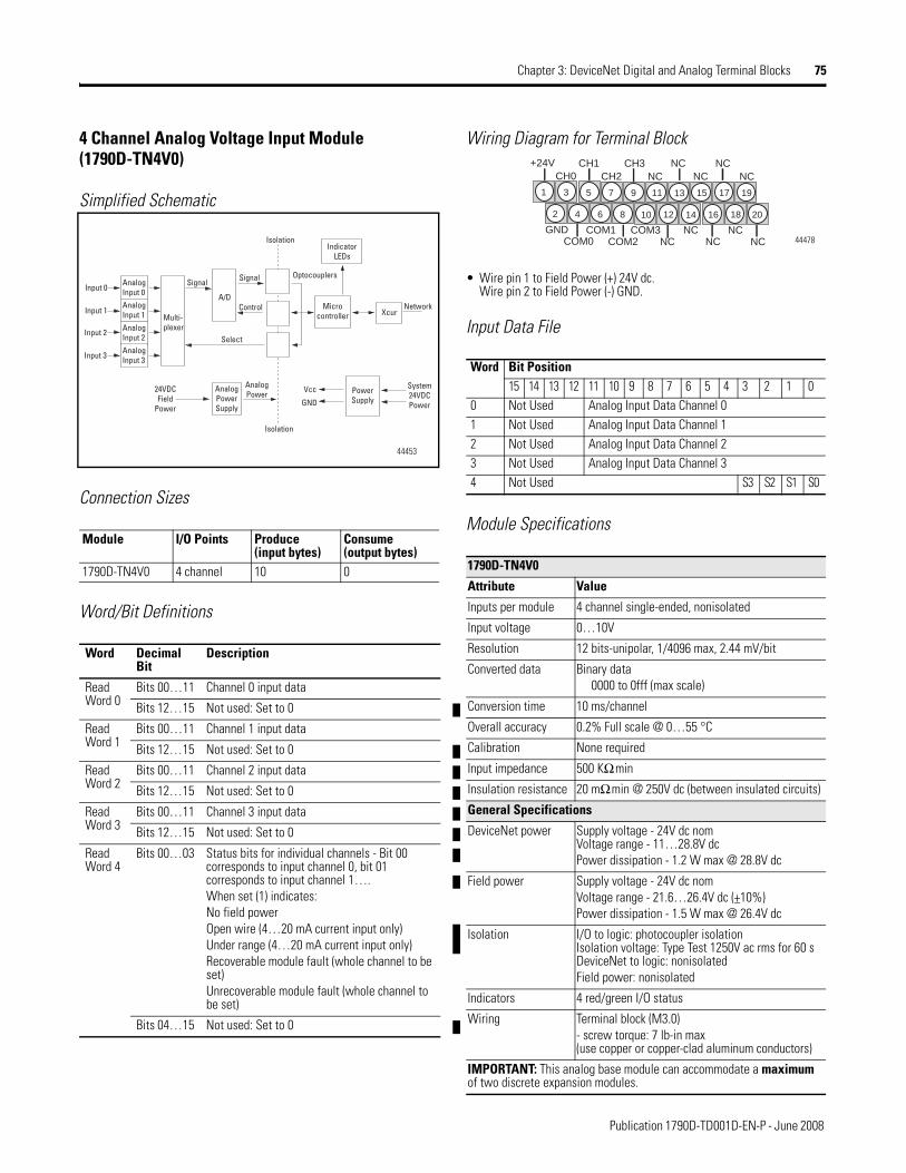
Publication 1790D-TD001D-EN-P - June 2008
Chapter 3: DeviceNet Digital and Analog Terminal Blocks 75
4 Channel Analog Voltage Input Module (1790D-TN4V0)
Simplified Schematic
Connection Sizes
Word/Bit Definitions
Wiring Diagram for Terminal Block
• Wire pin 1 to Field Power (+) 24V dc.Wire pin 2 to Field Power (-) GND.
Input Data File
Module SpecificationsModule I/O Points Produce
(input bytes)Consume (output bytes)
1790D-TN4V0 4 channel 10 0
Word Decimal Bit
Description
Read Word 0
Bits 00…11 Channel 0 input data
Bits 12…15 Not used: Set to 0
Read Word 1
Bits 00…11 Channel 1 input data
Bits 12…15 Not used: Set to 0
Read Word 2
Bits 00…11 Channel 2 input data
Bits 12…15 Not used: Set to 0
Read Word 3
Bits 00…11 Channel 3 input data
Bits 12…15 Not used: Set to 0
Read Word 4
Bits 00…03 Status bits for individual channels - Bit 00 corresponds to input channel 0, bit 01 corresponds to input channel 1….When set (1) indicates:No field powerOpen wire (4…20 mA current input only)Under range (4…20 mA current input only)Recoverable module fault (whole channel to be set)Unrecoverable module fault (whole channel to be set)
Bits 04…15 Not used: Set to 0
AnalogInput 0
AnalogInput 1
AnalogInput 2
AnalogInput 3
Input 0
Input 1
Input 2
Input 3
Signal
Multi-plexer
Isolation
A/D
Signal
Control
Select
Microcontroller Xcur
Network
Optocouplers
IndicatorLEDs
AnalogPowerSupply
AnalogPower
24VDCField
Power
PowerSupply
Vcc
GND
System24VDCPower
Isolation
44453
Word Bit Position15 14 13 12 11 10 9 8 7 6 5 4 3 2 1 0
0 Not Used Analog Input Data Channel 01 Not Used Analog Input Data Channel 12 Not Used Analog Input Data Channel 23 Not Used Analog Input Data Channel 34 Not Used S3 S2 S1 S0
1790D-TN4V0
Attribute Value
Inputs per module 4 channel single-ended, nonisolated
Input voltage 0…10V
Resolution 12 bits-unipolar, 1/4096 max, 2.44 mV/bit
Converted data Binary data 0000 to 0fff (max scale)
Conversion time 10 ms/channel
Overall accuracy 0.2% Full scale @ 0…55 °C
Calibration None required
Input impedance 500 KΩ min
Insulation resistance 20 mΩ min @ 250V dc (between insulated circuits)
General Specifications
DeviceNet power Supply voltage - 24V dc nomVoltage range - 11…28.8V dcPower dissipation - 1.2 W max @ 28.8V dc
Field power Supply voltage - 24V dc nomVoltage range - 21.6…26.4V dc (+10%)Power dissipation - 1.5 W max @ 26.4V dc
Isolation I/O to logic: photocoupler isolationIsolation voltage: Type Test 1250V ac rms for 60 sDeviceNet to logic: nonisolatedField power: nonisolated
Indicators 4 red/green I/O status
Wiring Terminal block (M3.0)- screw torque: 7 lb-in max (use copper or copper-clad aluminum conductors)
IMPORTANT: This analog base module can accommodate a maximum of two discrete expansion modules.
2018161412108642
191715131197531
NCNCNCCOM2COM0NCNCCOM3COM1GND
NCNCCH3CH1+24VNCNCNCCH2CH0
44478

Publication 1790D-TD001D-EN-P - June 2008
76 Chapter 3: DeviceNet Digital and Analog Terminal Blocks
Notes:


Publication 1790D-TD001D-EN-P - June 2008Supersedes Publication 1790D-TD001C-EN-P - July 2006 Copyright © 2008 Rockwell Automation, Inc. All rights reserved. Printed in the U.S.A.
Allen-Bradley, ArmorBlock, ArmorBlock MaXum, ArmorPoint, ControlLogix, CompactBlock I/O, CompactLogix, Dataliner, DeviceLink, DeviceLogix, DeviceView, DTAM Micro, DTAM Plus, Ezlink, FlexArmor, FLEX I/O, MicroLogix, On-Machine, PLC-5, PanelView, POINT I/O, PowerFlex, RediPANEL, RediSTATION, Rockwell Automation, RSNetWorx, RSNetWorx for DeviceNet, Series 9000, SoftLogix, SLC, SMC, SMC Dialog Plus, 1336 FORCE, and 1336 PLUS are trademarks of Rockwell Automation, Inc.
Trademarks not belonging to Rockwell Automation are property of their respective companies.