Embed Size (px)
Citation preview

8/13/2019 Compaction and Excavation
http://slidepdf.com/reader/full/compaction-and-excavation 1/56
Note: The source of the technical material in this volume is the ProfessionalEngineering Development Program (PEDP) of Engineering Services.
Warning: The material contained in this document was developed for SaudiAramco and is intended for the exclusive use of Saudi Aramco’s
employees. Any material contained in this document which is notalready in the public domain may not be copied, reproduced, sold, given,or disclosed to third parties, or otherwise used in whole, or in part,without the written permission of the Vice President, EngineeringServices, Saudi Aramco.
Chapter : Civil For additional information on this subject, contactFile Reference: CSE11605 K.S. Al-Yahyai on 874-2523
Engineering Encyclopedia Saudi Aramco DeskTop Standards
Compaction And Excavation
8/13/2019 Compaction and Excavation
http://slidepdf.com/reader/full/compaction-and-excavation 2/56
Engineering Encyclopedia Civil
Compaction And Excavation
Saudi Aramco DeskTop Standards
Contents Page
PLOTTING MOISTURE VS. DENSITY RELATIONSHIPS...............................1
SELECTING CONTROL TESTS USED IN DETERMININGMOISTURE-DENSITY RELATIONSHIPS..........................................................5
Laboratory Compaction Control Tests .......................................................5
Impact Compaction ....................................................................................5
Summary of Laboratory Tests for Compaction Control...........................11
Field Compaction Control Tests...............................................................12
CALCULATING PERCENT COMPACTION....................................................16
MATCHING FILL AND COMPACTION REQUIREMENTS FROMSAES-M-100 .......................................................................................................18
MATCHING COMPACTION EQUIPMENT TO SOIL TYPES ........................19
Smooth-Wheel or Drum Roller and Pneumatic-Tired Roller ...................20
Sheepsfoot Roller .....................................................................................20
Tamping-Foot Roller ................................................................................20
Mesh- or Grid-Pattern Roller....................................................................20
Vibration...................................................................................................23
IDENTIFYING PROBLEMS OF FIELD COMPACTION .................................24
DESCRIBING STRENGTH AND COMPRESSIBILITY OFCOMPACTED SOILS .........................................................................................26
Clays.........................................................................................................26
Sands ........................................................................................................26
CORRECT USE OF CALIFORNIA BEARING RATIO (CBR)VALUES..............................................................................................................27
Definition of CBR ....................................................................................27
Determining CBR Values.........................................................................27
ESTIMATING CBR OF IN-PLACE SOILS .......................................................31
8/13/2019 Compaction and Excavation
http://slidepdf.com/reader/full/compaction-and-excavation 3/56
Engineering Encyclopedia Civil
Compaction And Excavation
Saudi Aramco DeskTop Standards
IDENTIFYING SOIL EXCAVATION EQUIPMENT........................................33
Bulldozers.................................................................................................33
Backhoes, Draglines, and Clamshells.......................................................34Scrapers ....................................................................................................39
ESTIMATING SOIL EXCAVATION PRODUCTION RATES.........................40
IDENTIFYING ROCK EXCAVATION EQUIPMENT OR METHODS ...........41
Ripping .....................................................................................................41
Blasting and Rock Breakers .....................................................................46
Rock Blasting Terminology......................................................................47
Contract Definitions of Soil Versus Rock ................................................49
GLOSSARY ........................................................................................................51
8/13/2019 Compaction and Excavation
http://slidepdf.com/reader/full/compaction-and-excavation 4/56

8/13/2019 Compaction and Excavation
http://slidepdf.com/reader/full/compaction-and-excavation 5/56
Engineering Encyclopedia Civil
Compaction And Excavation
Saudi Aramco DeskTop Standards 2
MOISTURE VERSUS DENSITY CURVE
FIGURE 1
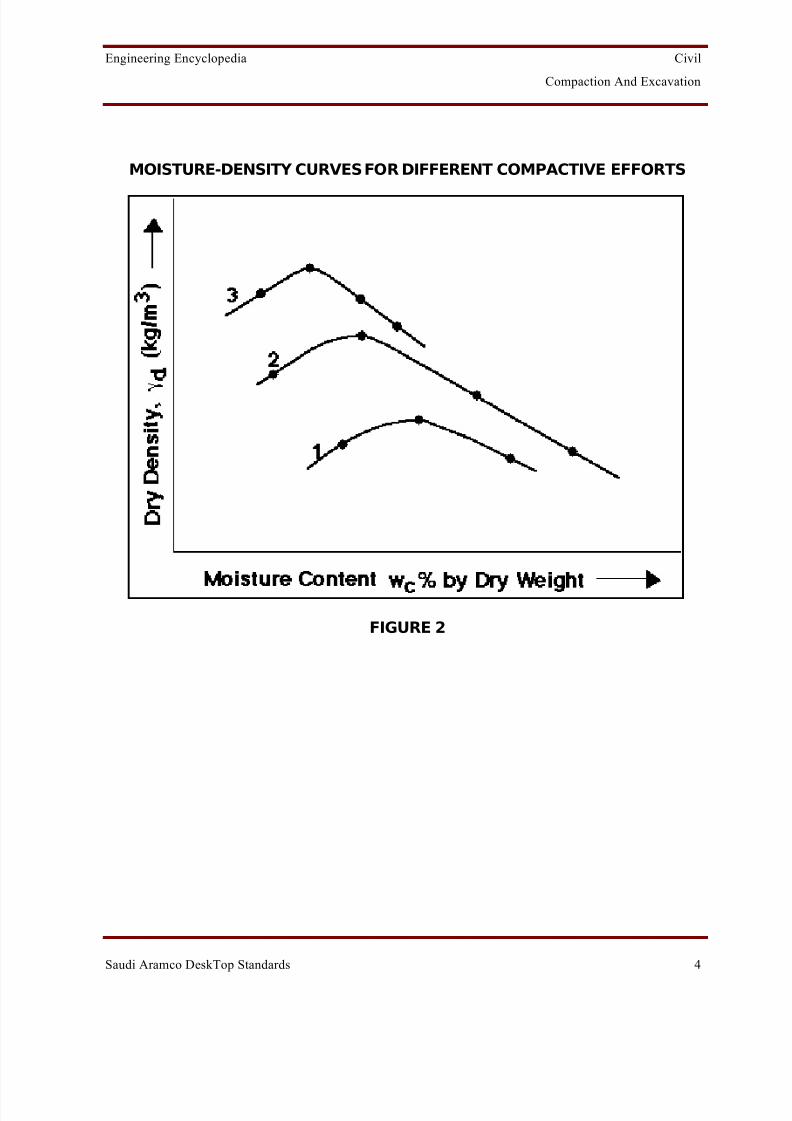
For the conditions of the test, the dry density at the peak of the curve is called the maximum dry densi ty , γ d(max), and the corresponding moisture content is called the optimum moisture content , w c(opt) , as shown in Figure 1. These are commonly used as indicators of themoisture content at which the soil should be compacted to obtain a high percentage of themaximum dry density. Neither of these quantities, that is, γ d(max) and w c(opt) , is a property of the soil itself. If, for example, all conditions are kept unchanged except that a higher compactive effort is used, the maximum dry density is higher and the optimum moisturecontent is lower.
The zero air voids curve or the complete saturation curve (Figure 1) shows densities for various moisture contents if the voids are entirely occupied with water, that is, 100%saturation. This curve is not attainable in practice because air always remains trapped in thesoil.
Curves similar to that in Figure 1 can be obtained for different compactive efforts as shown inFigure 2, where curve 1 corresponds to the lowest compactive effort and curve 3 to the
8/13/2019 Compaction and Excavation
http://slidepdf.com/reader/full/compaction-and-excavation 6/56
Engineering Encyclopedia Civil
Compaction And Excavation
Saudi Aramco DeskTop Standards 3
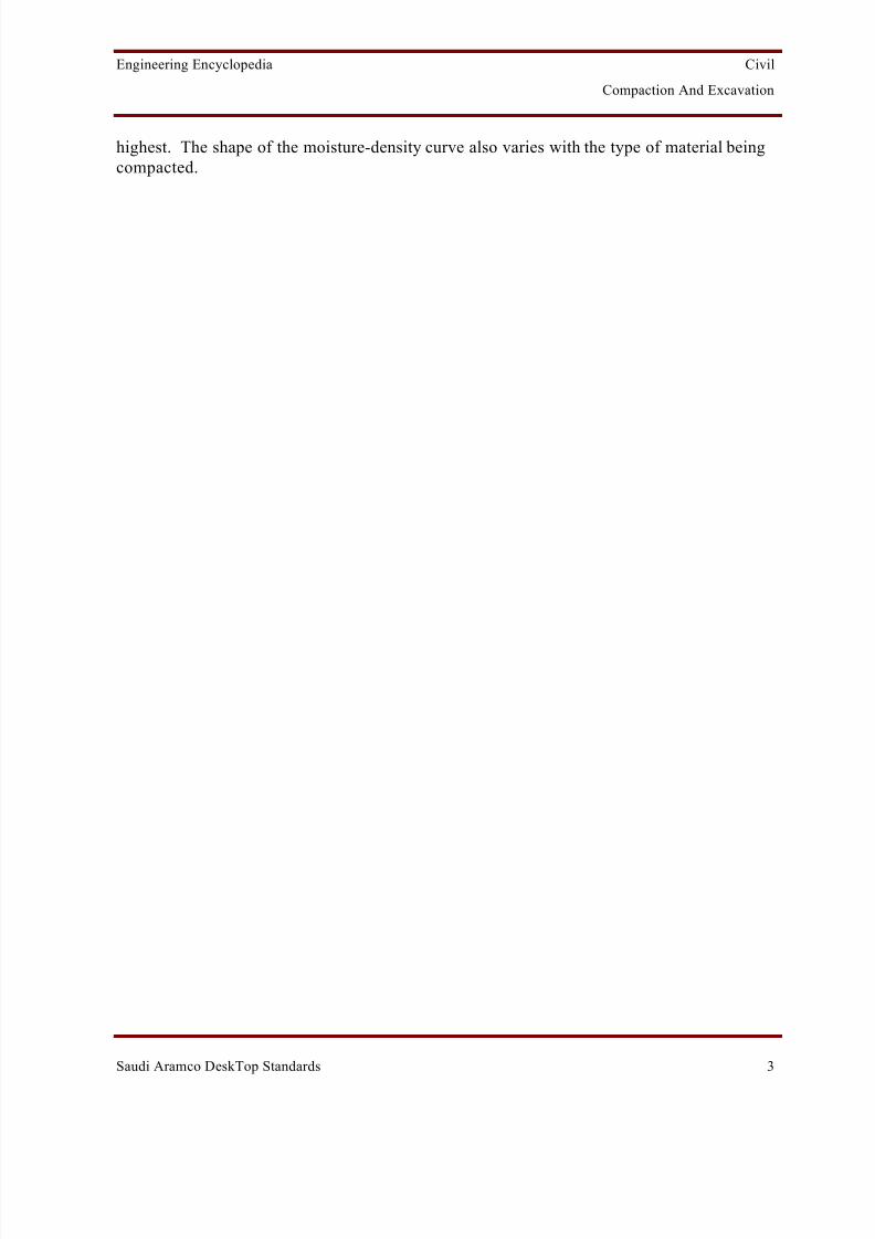
highest. The shape of the moisture-density curve also varies with the type of material beingcompacted.
8/13/2019 Compaction and Excavation
http://slidepdf.com/reader/full/compaction-and-excavation 7/56
Engineering Encyclopedia Civil
Compaction And Excavation
Saudi Aramco DeskTop Standards 4
MOISTURE-DENSITY CURVES FOR DIFFERENT COMPACTIVE EFFORTS
FIGURE 2
8/13/2019 Compaction and Excavation
http://slidepdf.com/reader/full/compaction-and-excavation 8/56
Engineering Encyclopedia Civil
Compaction And Excavation
Saudi Aramco DeskTop Standards 5
Selecting Control Tests Used in Determining Moisture-DensityRelationships
Laboratory Compaction Control Tests
The purpose of a laboratory compaction test is to determine in the laboratory a moisture-density curve comparable to that for the same material when compacted in the field. Theoptimum moisture content and maximum dry density are obtained from the curve and used tospecify field compaction requirements.
Impact Compaction
Impact compaction, where a metal hammer is dropped several times on a soil sample in amold, is the most common method used for standard laboratory tests. The mass of the
hammer, height of drop, number of drops, number of layers of soil, and the volume of themold are specified. Two such tests are widely used.
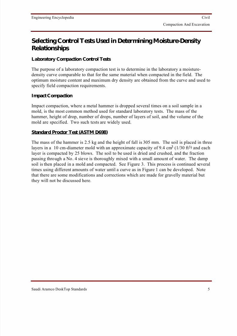
Standard Proctor Test (ASTM D698)
The mass of the hammer is 2.5 kg and the height of fall is 305 mm. The soil is placed in threelayers in a 10 cm-diameter mold with an approximate capacity of 9.4 cm 3 (1/30 ft 3) and eachlayer is compacted by 25 blows. The soil to be used is dried and crushed, and the fraction
passing through a No. 4 sieve is thoroughly mixed with a small amount of water. The dampsoil is then placed in a mold and compacted. See Figure 3. This process is continued severaltimes using different amounts of water until a curve as in Figure 1 can be developed. Note
that there are some modifications and corrections which are made for gravelly material butthey will not be discussed here.

8/13/2019 Compaction and Excavation
http://slidepdf.com/reader/full/compaction-and-excavation 9/56
Engineering Encyclopedia Civil
Compaction And Excavation
Saudi Aramco DeskTop Standards 6
STANDARD AASHTO* OR PROCTOR TEST
Modified Proctor Test (ASTM D1557)
This is used when a moisture-density relationship is desired for a higher compactive effort.The mold used is the same as the Standard Proctor mold. This test uses a heavier hammer (4.54 kg), falling from a greater height (457 mm), and compaction is done in 5 layers, whereeach layer is compacted by 25 blows. Besides being used for soil passing No. 4 sieve, thistest is also used when soils containing significant amounts of gravel are compacted. In thiscase the diameter of the mold used is 15.2 cm and the soil should pass a 2 cm sieve. SeeFigure 4.

8/13/2019 Compaction and Excavation
http://slidepdf.com/reader/full/compaction-and-excavation 10/56
Engineering Encyclopedia Civil
Compaction And Excavation
Saudi Aramco DeskTop Standards 7
MODIFIED AASHTO OR PROCTOR TEST
4.54 kg Hammer25 Blows Per Layer
Compactive Effort
457 mm
Soil Sample
9.4 cm (1/30 ft )
Five Layers
33
FIGURE 4

8/13/2019 Compaction and Excavation
http://slidepdf.com/reader/full/compaction-and-excavation 11/56
Engineering Encyclopedia Civil
Compaction And Excavation
Saudi Aramco DeskTop Standards 8
Determining Relative Density
Relative Density, D r , refers to an in-situ degree of compaction, relating the density of acohesionless granular (sandy) soil to its maximum density (the densest state to which a soilcan be compacted, D r = 100%) and the minimum density (the loosest state that dry soil grainscan attain, D r = 0%). Relative density is defined as:
Dr =emax - en
emax - emin, %
emax = void ratio of soil in loosest stateemin = void ratio of soil in densest stateen = existing void ratio of soil
Relative density can be defined in terms of unit weights as:
Dr =γ n - γ min
γ max - γ min γ max
γ n
where: γ = unit weight, insitu (n), maximum (max), and minimum (min).
The latter equation utilizing unit weights is more widely used because normal laboratory procedures use compaction molds with weight-volume measurements.
The concept of relative density applies only to cohesionless soils, not to silt or clay. It issometimes used for compaction control of cohesionless soils because the laboratory controltests more closely simulate the field compaction than do Proctor Tests. Two common testmethods are used in laboratories to determine the maximum and minimum index density.
8/13/2019 Compaction and Excavation
http://slidepdf.com/reader/full/compaction-and-excavation 12/56
Engineering Encyclopedia Civil
Compaction And Excavation
Saudi Aramco DeskTop Standards 9
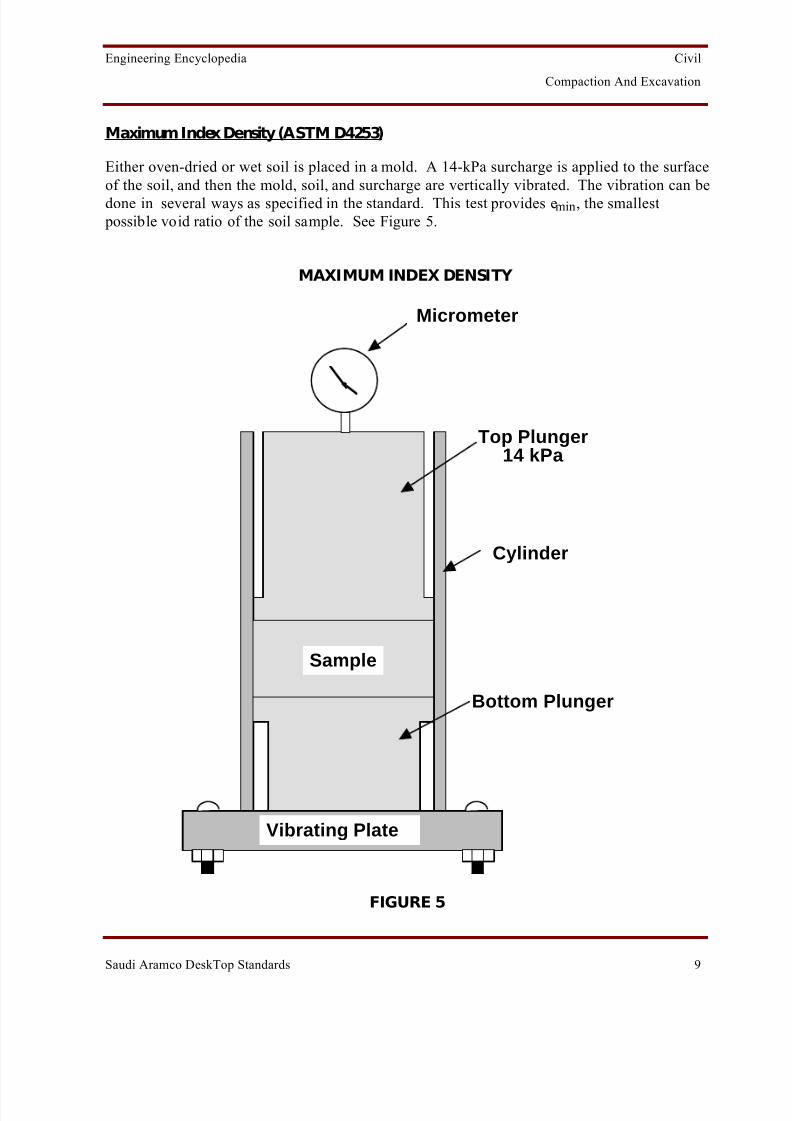
Maximum Index Density (ASTM D4253)
Either oven-dried or wet soil is placed in a mold. A 14-kPa surcharge is applied to the surfaceof the soil, and then the mold, soil, and surcharge are vertically vibrated. The vibration can bedone in several ways as specified in the standard. This test provides e min , the smallest
possible void ratio of the soil sample. See Figure 5.
MAXIMUM INDEX DENSITY
Sample
Vibrating Plate
Micrometer
Top Plunger14 kPa
Cylinder
Bottom Plunger
FIGURE 5

8/13/2019 Compaction and Excavation
http://slidepdf.com/reader/full/compaction-and-excavation 13/56
Engineering Encyclopedia Civil
Compaction And Excavation
Saudi Aramco DeskTop Standards 10
Minimum Index Density (ASTM D-4254)
A funnel pouring device or a hand scoop is used to place oven-dried soil into a mold or other container of known volume in such a manner that prevents the formation of lumps or dense
pockets or the segregation of particles according to size. Compaction of the soil should also be minimized. This test provides e max the largest possible void ratio of the soil sample . SeeFigure 6.
MINIMUM INDEX DENSITY
FIGURE 6
These two methods for determining relative density are applicable to soils in which 100%, bydry weight, of soil particles pass a 75-mm sieve and which may contain up to 30%, by dryweight, of soil particles retained on a 37.5-mm sieve. For sands with different particle-sizedistributions, slight variations of the above methods are used, as specified in the standards.

8/13/2019 Compaction and Excavation
http://slidepdf.com/reader/full/compaction-and-excavation 14/56
Engineering Encyclopedia Civil
Compaction And Excavation
Saudi Aramco DeskTop Standards 11
Summary of Laboratory Tests for Compaction Control
Determini ng Moisture-Density Relat ionships
Impact Compaction:
Standard Proctor Test - ASTM D698
Soil type: 100% passing No. 4 (4.75-mm) sieve.Mold: Diameter = 101.6 mm; capacity = 9.4 cm 3.Rammer: Weight = 2.5 kg; falling freely from a height = 305
mm.
Modifi ed Proctor Test - ASTM D1557
Soil type: 100% passing No. 4 (4.75 mm) sieve.Mold: Diameter = 101.6 mm; capacity = 9.4 cm 3.Rammer: Weight = 4.54 kg; falling freely from a height = 457
mm.
Note: For soils with gravel use a 2-cm sieve with a mold 10 cm in diameter.
Determini ng Relative Density
Maximum Index Density - ASTM D4253Minimum Index Density - ASTM D4254
Soil type (same for both): Free draining cohesionless soilswith 100%, by dry weight, passing75-mm sieve with a maximum of 30%, by dry weight, retained on a37.5-mm sieve.
Mold (same for both): Any container of known volume, preferably a mold similar to theProctor Mold.
Placement - ASTM D4253: Poured into mold and vibrated with
a small surcharge placed on top of soil.
- ASTM D4254: Poured into mold using a funnel or scoop so that no bulking or segregation occurs.

8/13/2019 Compaction and Excavation
http://slidepdf.com/reader/full/compaction-and-excavation 15/56
Engineering Encyclopedia Civil
Compaction And Excavation
Saudi Aramco DeskTop Standards 12
Field Compaction Control Tests
Field tests provide the field density information necessary to determine whether compactionspecifications are being met. The following three methods are common in Saudi Arabia.
Nuclear Densitometer Test (ASTM D2922)
This is a rapid, non-destructive technique for the in-place determination of wet density of soiland soil-aggregate using nuclear equipment. A gamma-ray source is used to pass gamma raysthrough the material being tested. The intensity of radiation after passage is recorded using agamma-ray detector. The radiation intensity reading is converted to measured wet density byusing correlation curves. See Figure 7.
NUCLEAR DENSITOMETER TEST
FIGURE 7

8/13/2019 Compaction and Excavation
http://slidepdf.com/reader/full/compaction-and-excavation 16/56
Engineering Encyclopedia Civil
Compaction And Excavation
Saudi Aramco DeskTop Standards 13
Nuclear Densitometer Test (ASTM D2922) (Cont'd)
Advantage:
The principal advantage of this test is the relative ease with which it can be performed(compared to methods such as the sand-cone and rubber-balloon, which involve digging holesand collecting and weighing bulky samples). This ease of operation makes this test particularlyuseful for the continuing control of construction, because many more tests can be performed per day than with other methods. In addition, apparently erratic measurements can be immediatelydetected and checked.
Disadvantages:
• Equipment maintenance and start-up costs are relatively high.
• Being a surface test [normally suitable to a test depth of approximately (5 to 30 cm), itsacrifices the opportunity to examine the soil in depth.
• The density determined by this method is not necessarily the average density within thevolume involved in the measurements; that is, the error can be high.
• The equipment utilizes radioactive materials which may be hazardous to the health of users unless proper precautions are taken.
Sand Cone Test (ASTM D1556)
This method determines the density of compacted soils used in the construction of earthembankments, road fill, and structure backfill. It is often used as the basis of compactioncontrol to check if the specified density has been achieved.
A hole 15 cm deep and 15 cm in diameter is dug and the material removed stored in a sealedcontainer for use in moisture content determination. The hole volume is measured withcalibrated sand and the density calculated by using the volume measurement and the weight of the material removed from the hole. For the apparatus used, see Figure 8.
This method can be used to determine in-place density of natural soil deposits, aggregates,
soil mixtures, or other similar material. The use of this method is generally limited to soil inan unsaturated condition and is not recommended for soils that are soft or crumble easily or that contain materials greater than 5 cm in diameter.

8/13/2019 Compaction and Excavation
http://slidepdf.com/reader/full/compaction-and-excavation 17/56
Engineering Encyclopedia Civil
Compaction And Excavation
Saudi Aramco DeskTop Standards 14
SAND CONE APPARATUS
Conversion Factor: 1 in. = 2.54 cm
Source: ASTM D1556FIGURE 8
8/13/2019 Compaction and Excavation
http://slidepdf.com/reader/full/compaction-and-excavation 18/56
Engineering Encyclopedia Civil
Compaction And Excavation
Saudi Aramco DeskTop Standards 15
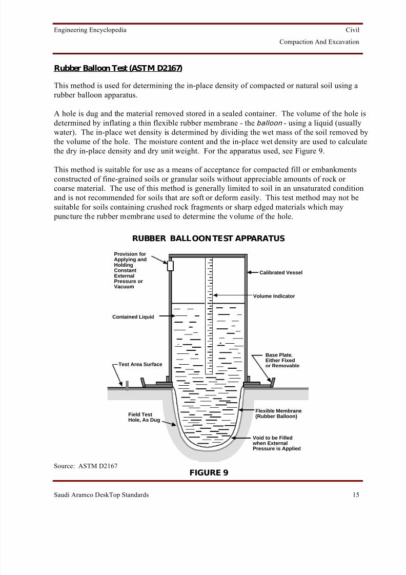
Rubber Balloon Test (ASTM D2167)
This method is used for determining the in-place density of compacted or natural soil using arubber balloon apparatus.
A hole is dug and the material removed stored in a sealed container. The volume of the hole isdetermined by inflating a thin flexible rubber membrane - the balloon - using a liquid (usuallywater). The in-place wet density is determined by dividing the wet mass of the soil removed bythe volume of the hole. The moisture content and the in-place wet density are used to calculatethe dry in-place density and dry unit weight. For the apparatus used, see Figure 9.
This method is suitable for use as a means of acceptance for compacted fill or embankmentsconstructed of fine-grained soils or granular soils without appreciable amounts of rock or coarse material. The use of this method is generally limited to soil in an unsaturated condition
and is not recommended for soils that are soft or deform easily. This test method may not besuitable for soils containing crushed rock fragments or sharp edged materials which may puncture the rubber membrane used to determine the volume of the hole.
RUBBER BALLOON TEST APPARATUS
Field TestHole, As Dug
Provision forApplying andHoldingConstantExternalPressure orVacuum
Contained Liquid
Test Area Surface
Calibrated Vessel
Volume Indicator
Base Plate,Either Fixedor Removable
Void to be Filled when ExternalPressure is Applied
Flexible Membrane(Rubber Balloon)
Source: ASTM D2167FIGURE 9

8/13/2019 Compaction and Excavation
http://slidepdf.com/reader/full/compaction-and-excavation 19/56
Engineering Encyclopedia Civil
Compaction And Excavation
Saudi Aramco DeskTop Standards 16
Calculating Percent Compaction
Example Problem: Computation of dry density for the sand cone tests.
For the given data from a sand cone test, calculate the dry density of the in-place material.
Given:
M s = Weight of sand to fill the test hole = 4.5 kgγ s = Bulk density of the test sand = 1762 kg/m 3
W = Wet weight of material removed from test hole = 5.4 kgandw = water content of material removed from test hole = 13%.
Solution:
Step 1 - Calculate the volume, V, of the test hole as the volume of sand neededto fill the test hole:
V = M s ÷ γ s = 0.0026 m 3 = 4.5 ÷ 1762 = 0.0026 m3
Step 2 - Calculate the dry weight, W s, of the material removed from the testhole:
A
W
S
Weight Volume
0
V = 0.0026 m 3W = 5.4 kg W w
Ws
W = W w + W s =5.4 kg
w% = 13% = 0.13 =WwWs
or W w = 0.13 W s

8/13/2019 Compaction and Excavation
http://slidepdf.com/reader/full/compaction-and-excavation 20/56
Engineering Encyclopedia Civil
Compaction And Excavation
Saudi Aramco DeskTop Standards 17
Calculating Percent Compaction (Cont'd)
Substituting:
W = 5.4 kg = 0.13 W s + W s
W s = 5.41.13
= 4.8 kg
Step 3 - Calculate the in-place wet density, γ w, and in-place dry density, γ d, of the material being tested:
γ w = W w ÷ V = 5.4
0.0026 = 2077 kg/m 3
γ d = W s ÷ V = 4.80.0026
= 1846 kg/m 3
8/13/2019 Compaction and Excavation
http://slidepdf.com/reader/full/compaction-and-excavation 21/56
Engineering Encyclopedia Civil
Compaction And Excavation
Saudi Aramco DeskTop Standards 18
Matching Fill and Compaction Requirements fromSAES-M-100
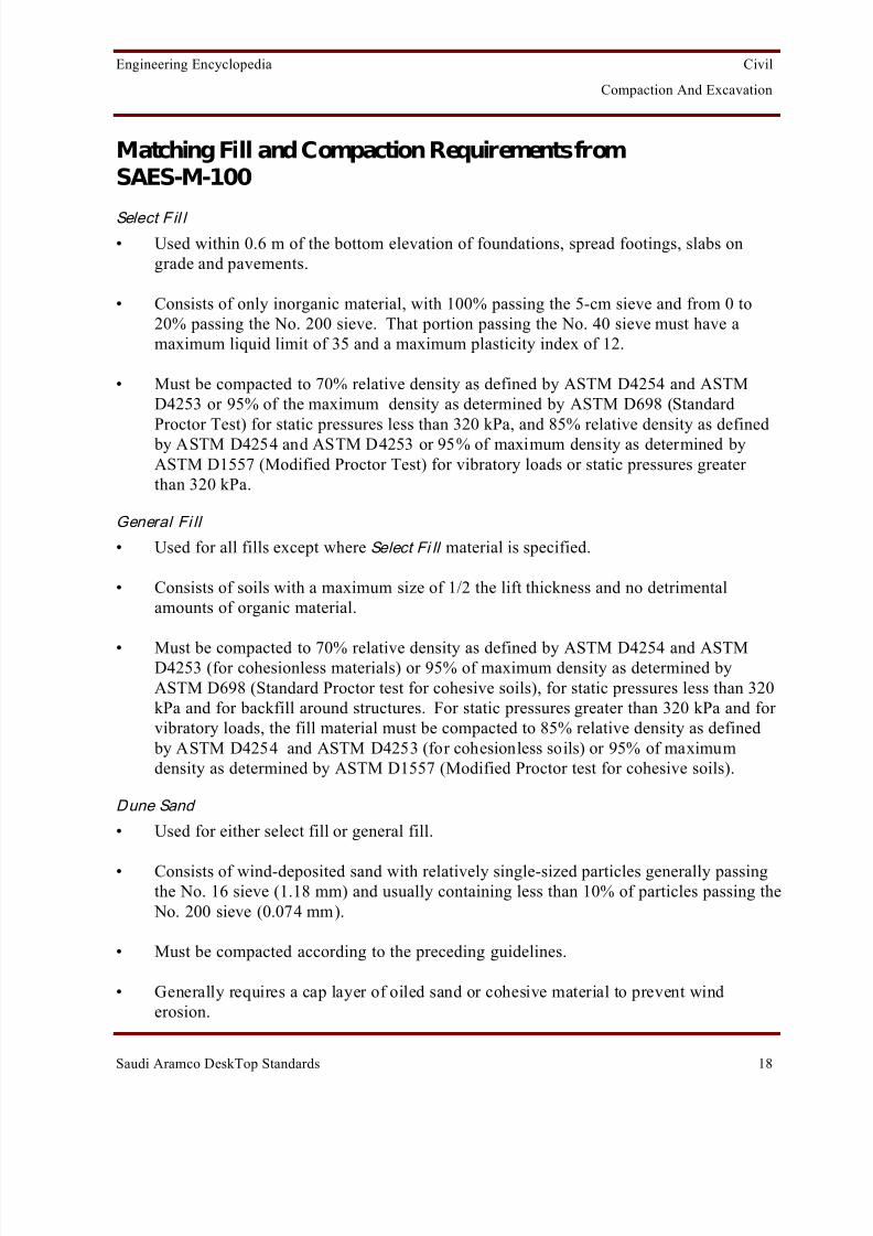
Select F il l • Used within 0.6 m of the bottom elevation of foundations, spread footings, slabs on
grade and pavements.
• Consists of only inorganic material, with 100% passing the 5-cm sieve and from 0 to20% passing the No. 200 sieve. That portion passing the No. 40 sieve must have amaximum liquid limit of 35 and a maximum plasticity index of 12.
• Must be compacted to 70% relative density as defined by ASTM D4254 and ASTMD4253 or 95% of the maximum density as determined by ASTM D698 (Standard
Proctor Test) for static pressures less than 320 kPa, and 85% relative density as defined by ASTM D4254 and ASTM D4253 or 95% of maximum density as determined byASTM D1557 (Modified Proctor Test) for vibratory loads or static pressures greater than 320 kPa.
General Fi ll
• Used for all fills except where Select Fi ll material is specified.
• Consists of soils with a maximum size of 1/2 the lift thickness and no detrimentalamounts of organic material.
• Must be compacted to 70% relative density as defined by ASTM D4254 and ASTMD4253 (for cohesionless materials) or 95% of maximum density as determined byASTM D698 (Standard Proctor test for cohesive soils), for static pressures less than 320kPa and for backfill around structures. For static pressures greater than 320 kPa and for vibratory loads, the fill material must be compacted to 85% relative density as defined
by ASTM D4254 and ASTM D4253 (for cohesionless soils) or 95% of maximumdensity as determined by ASTM D1557 (Modified Proctor test for cohesive soils).
Dune Sand
• Used for either select fill or general fill.
• Consists of wind-deposited sand with relatively single-sized particles generally passingthe No. 16 sieve (1.18 mm) and usually containing less than 10% of particles passing the
No. 200 sieve (0.074 mm).
• Must be compacted according to the preceding guidelines.
• Generally requires a cap layer of oiled sand or cohesive material to prevent winderosion.

8/13/2019 Compaction and Excavation
http://slidepdf.com/reader/full/compaction-and-excavation 22/56
Engineering Encyclopedia Civil
Compaction And Excavation
Saudi Aramco DeskTop Standards 19
Matching Compaction Equipment to Soil Types
The kind of compactor or roller used on a job will depend on the type of soil to be compacted.
Compaction of sands is best accomplished by impact or vibratory action, and of clays bykneading action. Equipment is available to apply pressure, impact, vibration, and kneading.Figure 10 shows the various soil types to be used with the various rollers.
RANGES OF SOIL TYPES FOR SOIL COMPACTION EQUIPMENT
RockSand100%
Sand/Clay50%
Clay100%
Sheepsfoot/Tamping Foot
Pneumatic Tire (50T and Up)
Smooth Wheel (Drum)
Vibratory
Mesh
Pattern
FIGURE 10
8/13/2019 Compaction and Excavation
http://slidepdf.com/reader/full/compaction-and-excavation 23/56
Engineering Encyclopedia Civil
Compaction And Excavation
Saudi Aramco DeskTop Standards 20
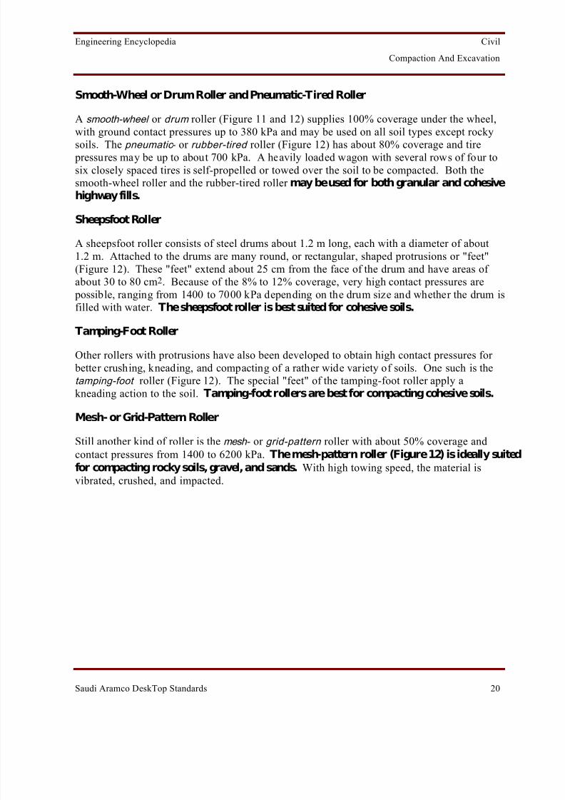
Smooth-Wheel or Drum Roller and Pneumatic-Tired Roller
A smooth-wheel or drum roller (Figure 11 and 12) supplies 100% coverage under the wheel,with ground contact pressures up to 380 kPa and may be used on all soil types except rockysoils. The pneumatic - or rubber-tired roller (Figure 12) has about 80% coverage and tire
pressures may be up to about 700 kPa. A heavily loaded wagon with several rows of four tosix closely spaced tires is self-propelled or towed over the soil to be compacted. Both thesmooth-wheel roller and the rubber-tired roller may be used for both granular and cohesivehighway fills.
Sheepsfoot Roller
A sheepsfoot roller consists of steel drums about 1.2 m long, each with a diameter of about1.2 m. Attached to the drums are many round, or rectangular, shaped protrusions or "feet"(Figure 12). These "feet" extend about 25 cm from the face of the drum and have areas of about 30 to 80 cm 2. Because of the 8% to 12% coverage, very high contact pressures are
possible, ranging from 1400 to 7000 kPa depending on the drum size and whether the drum isfilled with water. The sheepsfoot roller is best suited for cohesive soils.
Tamping-Foot Roller
Other rollers with protrusions have also been developed to obtain high contact pressures for better crushing, kneading, and compacting of a rather wide variety of soils. One such is thetamping-foot roller (Figure 12). The special "feet" of the tamping-foot roller apply akneading action to the soil. Tamping-foot rollers are best for compacting cohesive soils.
Mesh- or Grid-Pattern RollerStill another kind of roller is the mesh - or grid-pattern roller with about 50% coverage andcontact pressures from 1400 to 6200 kPa. The mesh-pattern roller (Figure 12) is ideally suitedfor compacting rocky soils, gravel, and sands. With high towing speed, the material isvibrated, crushed, and impacted.

8/13/2019 Compaction and Excavation
http://slidepdf.com/reader/full/compaction-and-excavation 24/56
Engineering Encyclopedia Civil
Compaction And Excavation
Saudi Aramco DeskTop Standards 21
SMOOTH-WHEEL ROLLER
FIGURE 11

8/13/2019 Compaction and Excavation
http://slidepdf.com/reader/full/compaction-and-excavation 25/56
Engineering Encyclopedia Civil
Compaction And Excavation
Saudi Aramco DeskTop Standards 22
TYPES OF ROLLERS
FIGURE 12

8/13/2019 Compaction and Excavation
http://slidepdf.com/reader/full/compaction-and-excavation 26/56
Engineering Encyclopedia Civil
Compaction And Excavation
Saudi Aramco DeskTop Standards 23
Vibration
Vibration is the most effective means of compacting granular soils such as sands and gravel.For small jobs, vibration can be produced by tamping with hand or pneumatic tools or bydropping heavy weights on the soil from a height of several feet. On larger jobs, effectivecompaction has been obtained of coarse sand and gravel and rockfill by means of 5 to 15 tonrollers equipped with vibrators operating at a frequency between about 100 and 1500 pulses
per minute. Figure 13 shows a vibratory drum on a smooth wheel roller in a towingconfiguration.
VIBRATING ROLLER
FIGURE 13

8/13/2019 Compaction and Excavation
http://slidepdf.com/reader/full/compaction-and-excavation 27/56
Engineering Encyclopedia Civil
Compaction And Excavation
Saudi Aramco DeskTop Standards 24
Identifying Problems of Field Compaction
Field compaction problems typically consist of:
• High compactive effort being applied, but compaction specification not being met.
• Low compactive effort being applied, but compaction specification being met.
Typical causes for these problems and their solutions include:
• Changed Materials: If the material tested in the lab is different from the material being placed in the field, then the γ dmax and w opt% determined in the lab will not apply to thefield.
Solution: Obtain proper lab values.
• Excess/Deficient Moisture: If the field moisture content of the soil is very different thanthe optimum moisture content, then it may not be possible to achieve the specified drydensity.
Solution: Add water or dry the soil as required.
• Lifts Too Thick: Fills are usually constructed by compacting the soil in layers calledlifts . A lift is spread and then compacted before the next lift is placed. Lift thicknessmay range from 150 to 500 mm or so, depending on the size and type of compactionequipment and on the maximum grain size of the soil being used for the fill. If the lift istoo thick, the compaction specification may not be achieved.
Solution: Reduce lift thickness.
• Wrong Compaction Equipment: Use of improper equipment can prevent compactionspecifications from being met. For example, use of a roller which is too light will resultin lower dry density being produced than is desirable. Or if vibratory equipment is usedfor cohesive soils, then proper compaction will not be achieved since vibratoryequipment is not effective in compacting cohesive soils.
Solution: Match compaction equipment to soil type.
• Base Too Soft for Compaction: Whenever possible, embankments are constructed onfirm, relatively incompressible subsoils. If the subsoil is soft, however, it may notwithstand the weight of compaction equipment being used on the overlying fill.Typically, the soil will move out from beneath the compactor and not receive the fullcompaction force.

8/13/2019 Compaction and Excavation
http://slidepdf.com/reader/full/compaction-and-excavation 28/56
Engineering Encyclopedia Civil
Compaction And Excavation
Saudi Aramco DeskTop Standards 25
Solution: Remove/replace the soft soils; accept less than the specified compaction for the first lift or two.
8/13/2019 Compaction and Excavation
http://slidepdf.com/reader/full/compaction-and-excavation 29/56
Engineering Encyclopedia Civil
Compaction And Excavation
Saudi Aramco DeskTop Standards 26
Describing Strength and Compressibility of Compacted Soils
Clays
The strength of compacted clays is rather complex. However, for the purpose of this course,it is enough to remember that compaction increases the strength and decreases thecompressibility of clays. In general, the greater the compaction, the higher the strength andthe lower the compressibility.
Sands
Void ratio is perhaps the most important single parameter that affects the strength of sands.Generally speaking, the lower the void ratio, the higher the shear strength. Compaction of sands increases the density, thus lowering the void ratio and increasing the strength. Anincrease in density also results in reducing the compressibility of sands.
Thus, compacted soils have high strength and low compressibility which is comparable to (or even better than) good quality natural soils.

8/13/2019 Compaction and Excavation
http://slidepdf.com/reader/full/compaction-and-excavation 30/56

8/13/2019 Compaction and Excavation
http://slidepdf.com/reader/full/compaction-and-excavation 31/56
Engineering Encyclopedia Civil
Compaction And Excavation
Saudi Aramco DeskTop Standards 28
CBR TESTING METHODS
Load
Standard Size Rod
Soil Samples
CBR Testing Cylinder
Laboratory Testing
FIGURE 14

8/13/2019 Compaction and Excavation
http://slidepdf.com/reader/full/compaction-and-excavation 32/56
Engineering Encyclopedia Civil
Compaction And Excavation
Saudi Aramco DeskTop Standards 29
CBR LOAD-DEFLECTION CURVES
FIGURE 15

8/13/2019 Compaction and Excavation
http://slidepdf.com/reader/full/compaction-and-excavation 33/56
Engineering Encyclopedia Civil
Compaction And Excavation
Saudi Aramco DeskTop Standards 30
Fi eld Testi ng
Field testing (ASTM D4429) involves penetrating a layer of soil in the field using a standardrod (plunger). The plunger is pushed into the ground against the reaction of a truck weight.
Again, load versus penetration data are taken, and a load-deflection curve is drawn. SeeFigure 16.
Field in-place bearing ratio (CBR) tests are generally performed on soils whose degree of saturation (percentage of voids filled with water) are 80% or greater; or when the soil iscoarse grained and cohesionless, so that it is not significantly affected by changes in water content.
CBR TESTING METHODS
Standard Size Rod
Field Testing
FIGURE 16
In both the laboratory and the field test, a surcharge load is applied to simulate confinement of the soil being tested. Laboratory test results give values for the CBR which are generallyhigher than those obtained with field testing. This is probably because of the effect of rigidconfinement in the laboratory mold.
8/13/2019 Compaction and Excavation
http://slidepdf.com/reader/full/compaction-and-excavation 34/56
Engineering Encyclopedia Civil
Compaction And Excavation
Saudi Aramco DeskTop Standards 31
Estimating CBR of In-Place Soils
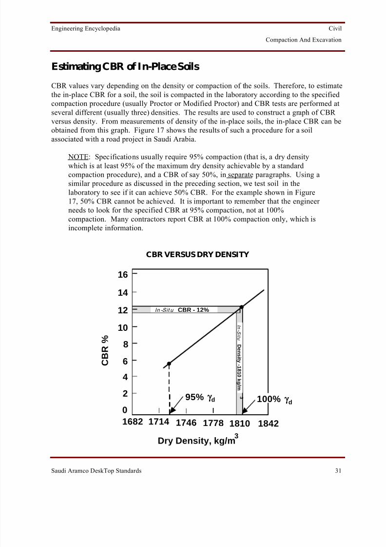
CBR values vary depending on the density or compaction of the soils. Therefore, to estimate
the in-place CBR for a soil, the soil is compacted in the laboratory according to the specifiedcompaction procedure (usually Proctor or Modified Proctor) and CBR tests are performed atseveral different (usually three) densities. The results are used to construct a graph of CBR versus density. From measurements of density of the in-place soils, the in-place CBR can beobtained from this graph. Figure 17 shows the results of such a procedure for a soilassociated with a road project in Saudi Arabia.
NOTE: Specifications usually require 95% compaction (that is, a dry densitywhich is at least 95% of the maximum dry density achievable by a standardcompaction procedure), and a CBR of say 50%, in separate paragraphs. Using asimilar procedure as discussed in the preceding section, we test soil in thelaboratory to see if it can achieve 50% CBR. For the example shown in Figure17, 50% CBR cannot be achieved. It is important to remember that the engineer needs to look for the specified CBR at 95% compaction, not at 100%compaction. Many contractors report CBR at 100% compaction only, which isincomplete information.
CBR VERSUS DRY DENSITY
16
14
12
10
8
6
4
2
01682 1714 1746 1778 1810 1842
C B R %
In -Sit u CBR - 12%
95% γ γ d 100% γ γ d
Dry Density, kg/m3
I n- S i t u
D en
si t y-1
8 1
0 k
g / m
3

8/13/2019 Compaction and Excavation
http://slidepdf.com/reader/full/compaction-and-excavation 35/56

8/13/2019 Compaction and Excavation
http://slidepdf.com/reader/full/compaction-and-excavation 36/56
Engineering Encyclopedia Civil
Compaction And Excavation
Saudi Aramco DeskTop Standards 33
Identifying Soil Excavation Equipment
Various types of equipment are used to excavate soil. Some of the most commonly used
types of equipment are bulldozers, backhoes, draglines, clamshells, and scrapers.
Bulldozers
Bulldozers, often just called dozers , consist of a large vertically curved blade held at a fixeddistance in front of a tractor. The blade can be raised or lowered, or tilted vertically, bymeans of cable controls or hydraulic rams. See Figure 18. The bulldozer has many uses. Itcan be used for clearing brush and grubbing roots and for felling trees. It is used for clearingtopsoil from the area to be excavated. Roads providing initial access to the construction areaare cut with the bulldozer, and it completes the building operation by backfilling andtrimming slopes. The bulldozer can be used for general excavation where the soils do not
require pushing farther than about 100 m. In general, dozers are used for moving smallamounts of material, usually for levelling and preparing uneven areas for further work. With bulldozers, the excavation depth is usually restricted to about 0.6 m. Another common usefor dozers is in a companion role to assist other excavation equipment.
BULLDOZER
FIGURE 18

8/13/2019 Compaction and Excavation
http://slidepdf.com/reader/full/compaction-and-excavation 37/56
8/13/2019 Compaction and Excavation
http://slidepdf.com/reader/full/compaction-and-excavation 38/56
Engineering Encyclopedia Civil
Compaction And Excavation
Saudi Aramco DeskTop Standards 35
Backhoes, Draglines, and Clamshells (Cont'd)
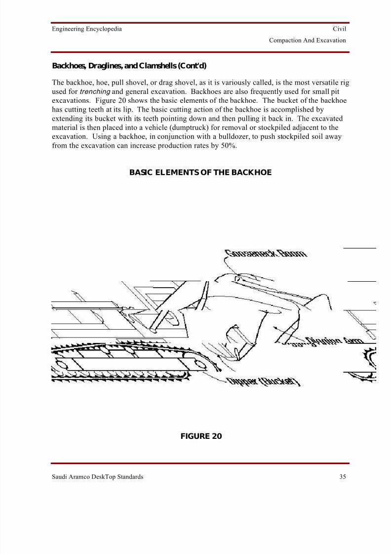
The backhoe, hoe, pull shovel, or drag shovel, as it is variously called, is the most versatile rigused for trenching and general excavation. Backhoes are also frequently used for small pitexcavations. Figure 20 shows the basic elements of the backhoe. The bucket of the backhoehas cutting teeth at its lip. The basic cutting action of the backhoe is accomplished byextending its bucket with its teeth pointing down and then pulling it back in. The excavatedmaterial is then placed into a vehicle (dumptruck) for removal or stockpiled adjacent to theexcavation. Using a backhoe, in conjunction with a bulldozer, to push stockpiled soil awayfrom the excavation can increase production rates by 50%.
BASIC ELEMENTS OF THE BACKHOE
FIGURE 20

8/13/2019 Compaction and Excavation
http://slidepdf.com/reader/full/compaction-and-excavation 39/56
Engineering Encyclopedia Civil
Compaction And Excavation
Saudi Aramco DeskTop Standards 36
Backhoes, Draglines, and Clamshells (Cont'd)
The dragline is most ideally suited to handle loose-bulk excavation. The dragline is basicallya scoop/bucket attached to a crane (Figure 21). The bucket is tossed out and allowed to drop.(No power is available for direct pressure on earth. The limited penetration is almost entirelyderived from the weight of the bucket.) Then the bucket is dragged back, gathering materialas it is pulled in by the drag cable. The dragline operates most efficiently from an elevationhigher than the material being dug and is seldom used for excavating at or above its travellevel. When the soil is very loose or when water occurs at some distance below the surface,the dragline is widely used in bulk-pi t excavation , in preference to regular power shovels.Under most conditions, it is also ideal for handling loose, dry sands and gravels. Some of thefunctions performed using a dragline are shown in Figure 22.
ELEMENTS OF THE DRAGLINE
FIGURE 21

8/13/2019 Compaction and Excavation
http://slidepdf.com/reader/full/compaction-and-excavation 40/56
Engineering Encyclopedia Civil
Compaction And Excavation
Saudi Aramco DeskTop Standards 37
VARIOUS USES OF THE DRAGLINE
(a) Excavating Channels and Canals
(b) Excavating Ditches and Trenches
(c) Excavating Underwater Soils
(e) Shallow Grading
(f) General Excavation
(g) Loading into Hoppers
(d) Stripping Overburden
(h) Sloping and Grading
(i) Loading Haul Units
FIGURE 22

8/13/2019 Compaction and Excavation
http://slidepdf.com/reader/full/compaction-and-excavation 41/56
Engineering Encyclopedia Civil
Compaction And Excavation
Saudi Aramco DeskTop Standards 38
Backhoes, Draglines, and Clamshells (Cont'd)
The clamshell consists of a clamshell bucket hung from the boom of a crane. The bucket hastwo jaws which clamp together (like a clam closing its shell ) to load by their weight when lifted
by the closing line. The two halves of the bucket are dropped in the open position onto thematerial to be excavated and the bucket closed, encompassing material between two halves.See Figure 23. The clamshell can be used for excavating foundations, footings, pier holes,trenches, and cellars, but its production rate is low. Where the soils being dug are loose, soft, or wet and require sheathing of their banks and, consequently, vertical lifting of the excavatedmaterial, the clamshell is ideal. The clamshell is also useful for selecting rock fragments from amixture of abundant rock fragments and soils. This last function is achieved by not closing the
bucket completely and thus retaining only material greater than a certain size due to the sievelike structure formed by the interlocking teeth of the bucket.
CLAMSHELL ELEMENTS
FIGURE 23

8/13/2019 Compaction and Excavation
http://slidepdf.com/reader/full/compaction-and-excavation 42/56
Engineering Encyclopedia Civil
Compaction And Excavation
Saudi Aramco DeskTop Standards 39
Scrapers
Scrapers are useful in moving large volumes of material quickly. Scrapers may be self-loading or only serve for transportation purposes, being loaded by a different operation.Figure 24 shows a self-loading, self-propelled scraper. Sometimes a scraper's self-loadingcapacity is assisted by pushing it with a tractor equipped with a bulldozer blade. The major operating components of the scraper are the bowl, the apron, and the ejector. The lip of the
bowl (or scoop) is armed with a replaceable cutting edge. In operation the bowl is tilteddownward until the cutting edge penetrates the soil 10-15 cm, depending on the density of thesoil formation. As the scraper is towed or pushed forward, a thin layer of earth is forced intothe bowl. When the bowl has been filled, it is tilted upward and the apron is dropped down toclose the bowl and prevent spillage during transportation to the unloading area. The ejector
plate is used to push out the earth from the bowl during unloading.
SELF-LOADING, SELF-PROPELLED SCRAPER
FIGURE 24
8/13/2019 Compaction and Excavation
http://slidepdf.com/reader/full/compaction-and-excavation 43/56
Engineering Encyclopedia Civil
Compaction And Excavation
Saudi Aramco DeskTop Standards 40
Estimating Soil Excavation Production Rates
Production rates for the various equipment depend on a number of factors, including:
• The size and dimensions of the excavation equipment.
• The nature of the soils.
• The size and depth of cut.
• The skill and efficiency of the operator.
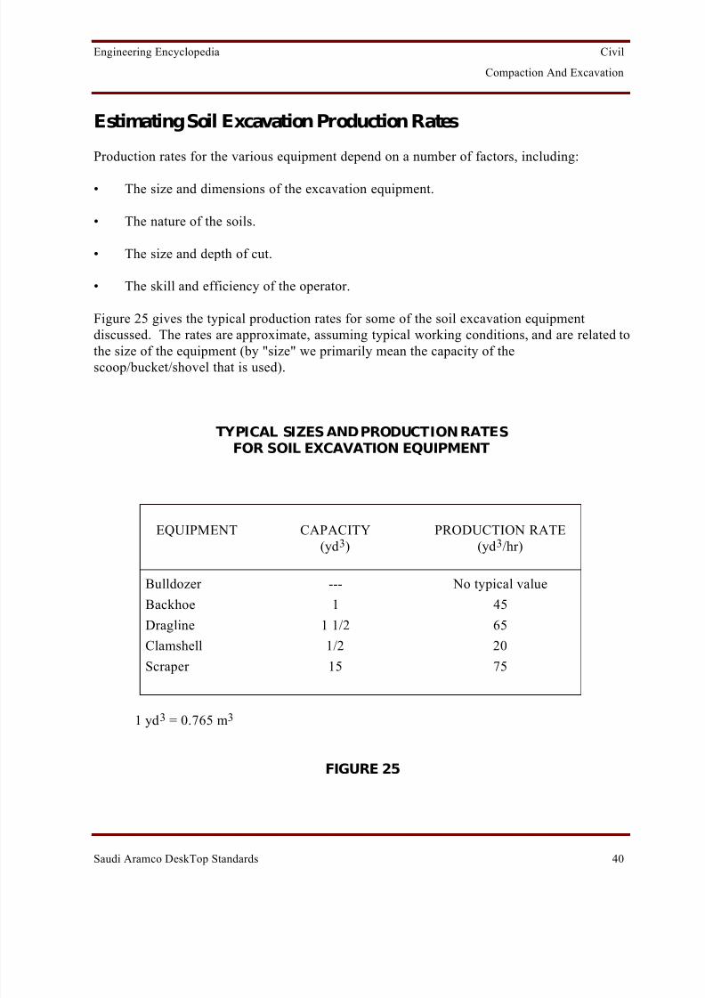
Figure 25 gives the typical production rates for some of the soil excavation equipmentdiscussed. The rates are approximate, assuming typical working conditions, and are related tothe size of the equipment (by "size" we primarily mean the capacity of thescoop/bucket/shovel that is used).
TYPICAL SIZES AND PRODUCTION RATESFOR SOIL EXCAVATION EQUIPMENT
EQUIPMENT CAPACITY(yd 3)
PRODUCTION RATE(yd 3/hr)
Bulldozer --- No typical value
Backhoe 1 45
Dragline 1 1/2 65
Clamshell 1/2 20
Scraper 15 75
1 yd 3 = 0.765 m 3
FIGURE 25

8/13/2019 Compaction and Excavation
http://slidepdf.com/reader/full/compaction-and-excavation 44/56
Engineering Encyclopedia Civil
Compaction And Excavation
Saudi Aramco DeskTop Standards 41
Identifying Rock Excavation Equipment or Methods
Ripping
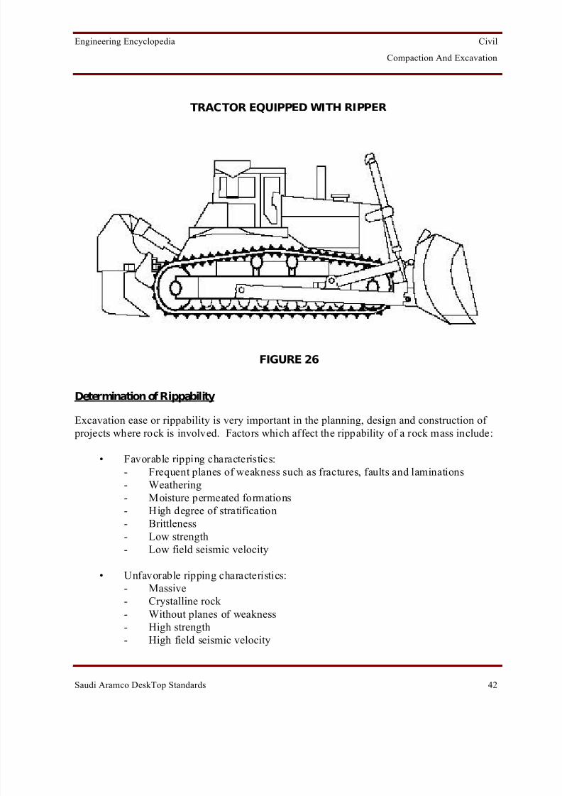
Ripping is a mechanical process for loosening and breaking rock into manageable sizes sothat it can be removed by standard excavating equipment, such as dozers and scrapers. As thetechnology and equipment improves, production ripping is being used more frequently in awide variety of rock conditions as an alternative to drilling and blasting operations, which arealways slower and more costly.
As shown in Figure 26, a steel ripper which resembles an angled tooth is pulled through arock mass by a heavy tractor (usually a bulldozer). By making continuous passes, the ripper loosens and breaks the rock to such a degree that it is easily removed with conventionalequipment.
Choosing the appropriate tractor and ripper should consider several factors. The tractor musthave sufficient horsepower to advance the ripper once it penetrates the rock mass. The tractor must also be of sufficient weight to develop the traction to use the available horsepower.Finally, there must be enough downpressure on the ripper so that tip penetration can beobtained and maintained.
Rippers may be of the fixed or hydraulically adjustable type and are available with single or multiple shanks (teeth). For additional penetration and ripping capability, impact rippers arealso available. The ripper penetrates the rock using a combination of its own weight and/or hydraulics and the forward thrust from the tractor. The depth of penetration depends on a
number of factors including the rock hardness, equipment used, bedding thickness and degreeof fracturing and project requirements. Average penetration depths of 0.6 m are common.
8/13/2019 Compaction and Excavation
http://slidepdf.com/reader/full/compaction-and-excavation 45/56
Engineering Encyclopedia Civil
Compaction And Excavation
Saudi Aramco DeskTop Standards 42
TRACTOR EQUIPPED WITH RIPPER
FIGURE 26
Determination of Rippability
Excavation ease or rippability is very important in the planning, design and construction of projects where rock is involved. Factors which affect the rippability of a rock mass include:
• Favorable ripping characteristics:- Frequent planes of weakness such as fractures, faults and laminations- Weathering- Moisture permeated formations- High degree of stratification- Brittleness- Low strength- Low field seismic velocity
• Unfavorable ripping characteristics:- Massive- Crystalline rock - Without planes of weakness- High strength- High field seismic velocity

8/13/2019 Compaction and Excavation
http://slidepdf.com/reader/full/compaction-and-excavation 46/56
Engineering Encyclopedia Civil
Compaction And Excavation
Saudi Aramco DeskTop Standards 43
Determination of Rippability (Cont'd)
In general, igneous rocks are the most difficult to rip because of their lack of stratificationand cleavage planes. Igneous rocks are usually rippable only where they are highlyweathered and/or highly fractured. Metamorphic rocks vary in rippability depending on their degree of foliation or stratification. Sedimentary rock offers the best opportunity for rippingdue to their stratification.
Methods commonly used to assess rippability include field observation in similar materials or by using seismic velocity, fracture spacing, or point load strength index. The most accuratemethod is to observe a field test in similar materials or the actual material using differenttractors and/or rippers. Where this is not feasible or practical, measuring the seismic velocityof the rock mass is recommended. Figure 27 illustrates rippability of surface materials relatedto longitudinal seismic velocity for a heavy ripper (greater than 45 tons and 350 hp for
example, a D-9 bulldozer). In general the lower the seismic velocity the higher the probability the material is rippable.
RIPPABILITY OF SUBSURFACE MATERIALS RELATED TO LONGITUDINALSEISMIC VELOCITY FOR A HEAVY DUTY RIPPER (TRACTOR MOUNTED)
FIGURE 27

8/13/2019 Compaction and Excavation
http://slidepdf.com/reader/full/compaction-and-excavation 47/56
8/13/2019 Compaction and Excavation
http://slidepdf.com/reader/full/compaction-and-excavation 48/56
Engineering Encyclopedia Civil
Compaction And Excavation
Saudi Aramco DeskTop Standards 45
Determination of Rippability (Cont'd)
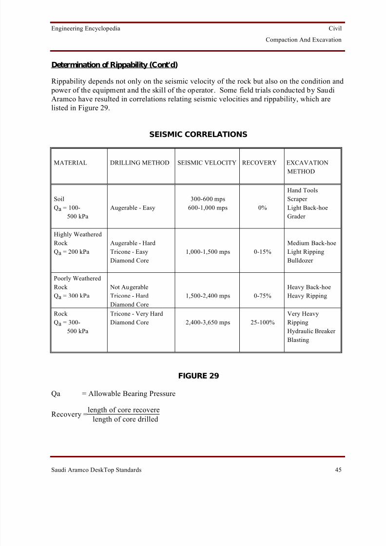
Rippability depends not only on the seismic velocity of the rock but also on the condition and power of the equipment and the skill of the operator. Some field trials conducted by SaudiAramco have resulted in correlations relating seismic velocities and rippability, which arelisted in Figure 29.
SEISMIC CORRELATIONS
MATERIAL DRILLING METHOD SEISMIC VELOCITY RECOVERY EXCAVATIONMETHOD
SoilQa = 100- 500 kPa
Augerable - Easy300-600 mps
600-1,000 mps 0%
Hand ToolsScraper Light Back-hoeGrader
Highly WeatheredRock Qa = 200 kPa
Augerable - HardTricone - EasyDiamond Core
1,000-1,500 mps 0-15%Medium Back-hoeLight RippingBulldozer
Poorly Weathered
Rock Qa = 300 kPa
Not AugerableTricone - HardDiamond Core
1,500-2,400 mps 0-75%Heavy Back-hoeHeavy Ripping
Rock Qa = 300- 500 kPa
Tricone - Very HardDiamond Core 2,400-3,650 mps 25-100%
Very HeavyRippingHydraulic Breaker Blasting
FIGURE 29
Qa = Allowable Bearing Pressure
Recovery = length of core recoverelength of core drilled

8/13/2019 Compaction and Excavation
http://slidepdf.com/reader/full/compaction-and-excavation 49/56
Engineering Encyclopedia Civil
Compaction And Excavation
Saudi Aramco DeskTop Standards 46
Blasting and Rock Breakers
Har d rock is interpreted by Saudi Aramco as intact rock which requires breaking or drillingand blasting for removal. Hard rock excavation is also used for rock, concrete, or other intact(not granular) material requiring jackhammers to break it up for removal.
When ripping methods are unsuccessful, excavation in hard rock usually involves blasting.Explosives are used to break rock masses into smaller fragments which are then loaded intotrucks, using power shovels and loaders, for transportation. In situations where blasting is notfeasible due to cost or safety limitations, jackhammers and hydraulic rock breakers are used.
Virtually all types of blasting require drilling a hole in which explosives are placed. For general rock drilling, equipment driven by compressed air is universally employed. Mostsuch drills are mounted on tractors. Figure 30 shows a line diagram of a tractor-mounted drill
used to drill blast holes.
The breakup of rock formations by blasting or other methods is not a precise operation. Anumber of factors need to be accounted for. These are dependent on type of rock and the kindof formation it occurs in, and the type of explosive to be used.
TRACTOR-MOUNTED BLAST DRILL
FIGURE 30

8/13/2019 Compaction and Excavation
http://slidepdf.com/reader/full/compaction-and-excavation 50/56
Engineering Encyclopedia Civil
Compaction And Excavation
Saudi Aramco DeskTop Standards 47
Rock Blasting Terminology
Some common rock blasting terminology is discussed next. Refer to Figure 31 for illustrations of some of the terms discussed.
• Burden, B.
The distance from the explosive charge to the nearest free or open face is called the burden. This distance is measured perpendicular to the face as illustrated in Figure 30.There are many empirical relationships for approximating the burden for variousexplosive-rock combinations. Burden is the most important parameter in blasting design.All other design parameters are direct functions of the initial burden.
• Spacing, S.
Spacing is normally measured as the distance between drill holes (containing explosivecharges) in a row (hole spacing) and the distance between parallel rows (spacing or rowspacing) of explosive charges. Spacing is the second most important parameter in
blasting design, because it effects mutual interaction of the different charges and thuscontrols the development of stress patterns which in turn control the method or rock
breakage.
• Powder Factor, PF.
The powder factor relates the yield of material blasted to the quantity of explosive used.
For most construction, it is customarily expressed in pounds of explosive per cubic yardof material excavated (g/m 3).
Because of its extremely variable character, the PF is not normally a sound index uponwhich to design blasts. Its value will be very dependent on the displacement andfragmentation desired and especially on the properties of the explosive used andmaterial blasted.
• Hole Stemming, T.
The filling of part of the blast hole with inert material, such as sand, drillings, and clay to
confine the explosive gases is called hole stemming. Normally, only the part above theexplosive charge is filled. This is done for safety reasons as well as to ensure that most of the explosive energy is used to break the rock and is not wasted by being discharged upthrough the drill hole in which the explosive is placed. The amount of stemming, T, thatshould be used will be a direct function of the burden, B. Normally, stemming amountsequal to but not less than two-thirds of the burden are satisfactory.

8/13/2019 Compaction and Excavation
http://slidepdf.com/reader/full/compaction-and-excavation 51/56

8/13/2019 Compaction and Excavation
http://slidepdf.com/reader/full/compaction-and-excavation 52/56
Engineering Encyclopedia Civil
Compaction And Excavation
Saudi Aramco DeskTop Standards 49
Trench Excavation Versus General Excavation
When excavation is to be done in trenches or small areas, the definition of "Rock Excavation" mayneed to be modified because ripping is only possible to about 1 m depth in such situations. Somerock which could be ripped in a general excavation (soil excavation rates) may thus require ahydraulic rock breaker with a heavy backhoe to excavate the material (rock excavation rates).
Type of excavation (trench versus general) is therefore as important as rock properties indetermining hard-rock versus soft-rock excavation.
Contract Definitions of Soil Versus Rock
Saudi Aramco currently has no definition of Rock Excavation other than what is inSAES-M-100, and that definition is subject to interpretation. It is important to have clear definitions of hard rock and soft r ock for every project to avoid field delays, contract claims,
and change orders. Standard clauses exist so each contract must be specific for the case.Experience has shown that as long as "Rock Excavation" is clearly defined, claims forexcess rock excavation are fewer and easier to evaluate. Some proposed definitions of rock excavation based on rippability and seismic velocity are:
PROPOSED DEFINITIONS OF ROCK EXCAVATION
TYPE OF EXCAVATION ROCK EXCAVATION DEFINITION
Hand excavation required: Rock, concrete, or other intact (not granular) materialrequiring jackhammers for removal.
Material with seismic velocities in excess of 900 mps.
Trenches/smallexcavations:
Hard rock which demonstratively cannot be excavated by a heavy backhoe in good condition without the aid of hydraulic rock breakers.
Material with seismic velocities in excess of 1500 mps.
General excavations: Hard rock which demonstratively cannot be ripped witha D-9 dozer in good condition without the aid of
hydraulic rock breakers or blasting.
Material with seismic velocities in excess of 2400 mps.
FIGURE 32
8/13/2019 Compaction and Excavation
http://slidepdf.com/reader/full/compaction-and-excavation 53/56
Engineering Encyclopedia Civil
Compaction And Excavation
Saudi Aramco DeskTop Standards 50
WORK AID 1: Steps for Calculating Percent Compaction
Directions:
As a first step for Exercise 3, draw the moisture-density curve for the given laboratory testingdata and obtain the values of the following:
Optimum Moisture Content, w (opt) , =
Maximum Dry Density, γ d(max) , =
Next, recall the weight volume relationships you learned earlier and calculate the dry densityof the compacted soil in the field using the field testing data supplied in the question:
Field dry density, γ d(field) , =
Finally, use the two dry density values obtained to calculate the percent compaction.
Percent compaction =
8/13/2019 Compaction and Excavation
http://slidepdf.com/reader/full/compaction-and-excavation 54/56
Engineering Encyclopedia Civil
Compaction And Excavation
Saudi Aramco DeskTop Standards 51
GLOSSARY
auger A rotating drill having a screw thread that carries cuttings away
from the surface being drilled.
backfill Earth/rock used to replace material previously removed byexcavation.
backhoe Self-powered excavation equipment that digs by pulling a boommounted bucket toward itself. It also has a front bucket.
blast To loosen or move rock/earth by means of explosives or anexplosion.
blasthole A drill hole used for a charge of explosives.
blasthole drill A drill of any type used in the drilling of blastholes, usually air percussion, cable, rotary, or fusion-type.
borehole Hole drilled into rock for exploration or blasting.
borrow pit/area An excavation from which material is taken for a nearby job.
bulking Increase in volume of fine materials due to loosening or moisturecontent increase.
burden The distance of a blasthole from the face or the volume of rock to be moved by the explosive in each blasthole.
california bearingratio (CBR)
Penetration test performed to determine the potential strength of subgrade, subbase and base course material for use in road andairfield pavements.
clamshell A bucket with two jaws, which clamp together to load by their ownweight when lifted by the closing line.
compaction Reduction in volume of fill or embankment by rolling, tamping,and wetting the material.
compactive effort A measure of the mechanical energy applied to a soil mass.
compactor A machine for compacting soil. It can be towed or self-powered.

8/13/2019 Compaction and Excavation
http://slidepdf.com/reader/full/compaction-and-excavation 55/56
Engineering Encyclopedia Civil
Compaction And Excavation
Saudi Aramco DeskTop Standards 52
embankment A fill the top of which is higher than the surrounding surface. Anembankment is usually compacted.
excavation The cutting down of the natural ground surface, the material takenfrom the excavation, or the space formed by the removal of thematerial. Also known as cutting .
face The more or less vertical surface of rock exposed by excavation or blasting.
fill To place earth, or the earth which has been placed. Also calledembankment , especially if compacted.
fines The soil particles passing the #200 sieve (silt and clay size
particles).
finish grade The final grade called for by the specifications.
grade (1) The profile of the center of a road, channel, or natural groundarea.(2) To prepare the ground by cutting and filling according to adefinite plan.(3) The gradient, that is, the percentage of rise or fall to thehorizontal distance.
lift A layer of material or soil placed during filling.
loose bulk excavation
Excavation, in quantity, of loose, unconsolidated soils, of soilslying under water, or of soils so saturated with water as to preventmovement of equipment over their surface. Loose bulk excavationis generally performed from solid, or relatively solid, groundadjacent to the area being excavated.
maximum densityand optimummoisture
The highest density achievable for a given compactive effort andmethod. The moisture content at which maximum dry density isachieved.
moisture-densitycurve
A graph relating dry density to moisture content.
ripper Teeth-shaped attachments added to equipment to dig through hardor rocky soil or soft rock.

8/13/2019 Compaction and Excavation
http://slidepdf.com/reader/full/compaction-and-excavation 56/56
Engineering Encyclopedia Civil
Compaction And Excavation
scraper A digging, hauling, and grading machine having a cutting edge, acarrying bowl, a movable front wall, and a dumping mechanism.
sheepsfoot roller A compacting roller with feet expanded at their outer tips. Used incompacting cohesive soil.
subgrade The uppermost level of material placed in an embankment or left atcuts in the normal grading of a road bed. This becomes thefoundation for aggregate and asphalt pavement.
vibratory roller A self-powered or towed compacting device which mechanicallyvibrates while it rolls. Used for cohesionless soils.
zero air voids curve A curve showing densities for various moisture contents if the
voids are entirely occupied with water. Also known as thecomplete saturation curve.