Embed Size (px)
Citation preview
ENVIRONMENTAL GEOTECHNICS
Compaction
Prof. Ing. Marco Favaretti
University of PadovaDepartment of Civil, Environmental and Architectural EngineeringVia Ognissanti, 39129 Padova (Italy)
phone: +39.049.827.7901e-mail: [email protected]: www.marcofavaretti.net
1
2
INTRODUCTION
Soils may be weak, highly compressible, or have a higherpermeability than desirable from an engineering oreconomic point of view.
It would seem reasonable in such instances to relocatethe structure or facility.
The geotechnical engineer is often forced to design in anunsuitable site.
3
INTRODUCTION
One possibility is to adapt the foundation to thegeotechnical conditions at the site.
Another possibility is to try to compact or stabilizeor improve soil, increasing the engineeringproperties of soils.
Depending on various factors this second approach may be the cheapest solution to the problem.
4
With terms soil mechanical modification we define the improvement of soil caused by external forces.
Terms as mechanical modification and compaction are often considered as synominous.
Geotechnical engineer distinguishes the following three terms:
1 – compaction
2 – stabilization
3 – consolidation
INTRODUCTION
5
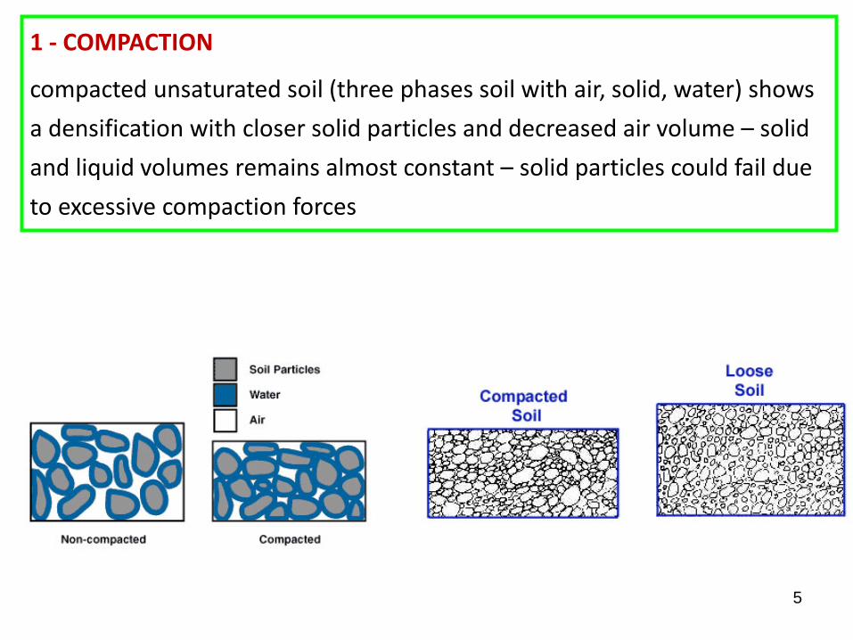
1 - COMPACTION
compacted unsaturated soil (three phases soil with air, solid, water) shows a densification with closer solid particles and decreased air volume – solid and liquid volumes remains almost constant – solid particles could fail due to excessive compaction forces
6
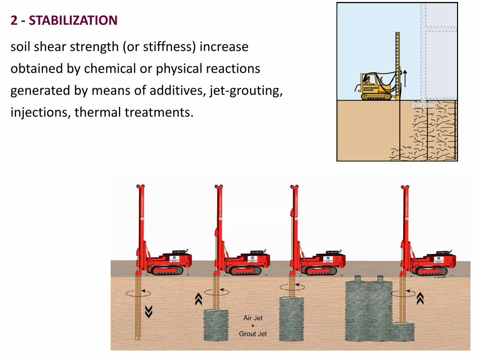
2 - STABILIZATION
soil shear strength (or stiffness) increase obtained by chemical or physical reactions generated by means of additives, jet-grouting, injections, thermal treatments.
7
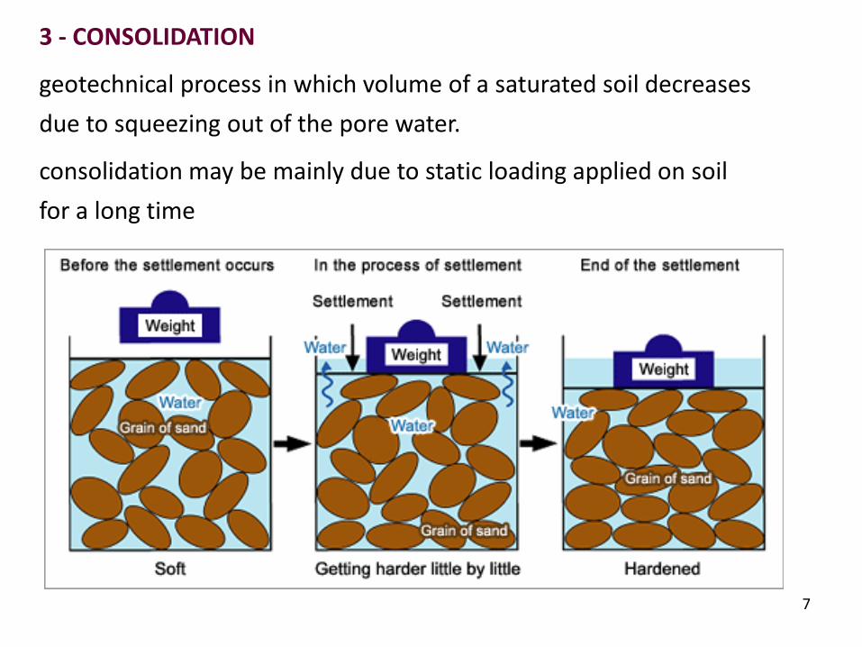
3 - CONSOLIDATION
geotechnical process in which volume of a saturated soil decreases due to squeezing out of the pore water.
consolidation may be mainly due to static loading applied on soil for a long time
8
Compaction is very important when soil is used as an engineering material(earth dams, road embankments, river levees).
If soils are dumped (or otherwise placed at random in a fill) the result willbe an embankment with low stability and high settlement.
Before the 30’s highway and railroad fills were usually constructed by end-dumping soils from wagons or trucks.
There was very little attempt to compact or to densify the soils, andfailures of even moderately high embankments were common.
Earthworks such as levees are almost as old as man, but these structures(ancient China or India), were constructed by people carrying smallbaskets of earth and dumping them in the embankment.
COMPACTION
9
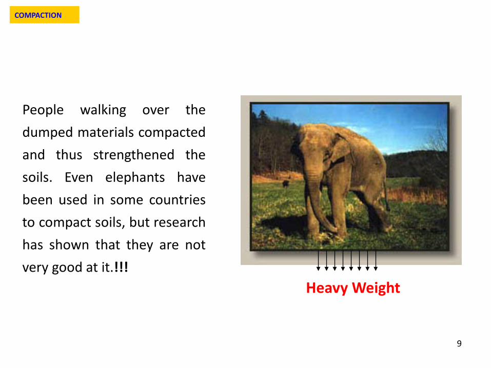
People walking over thedumped materials compactedand thus strengthened thesoils. Even elephants havebeen used in some countriesto compact soils, but researchhas shown that they are notvery good at it.!!!
Heavy Weight
COMPACTION
10
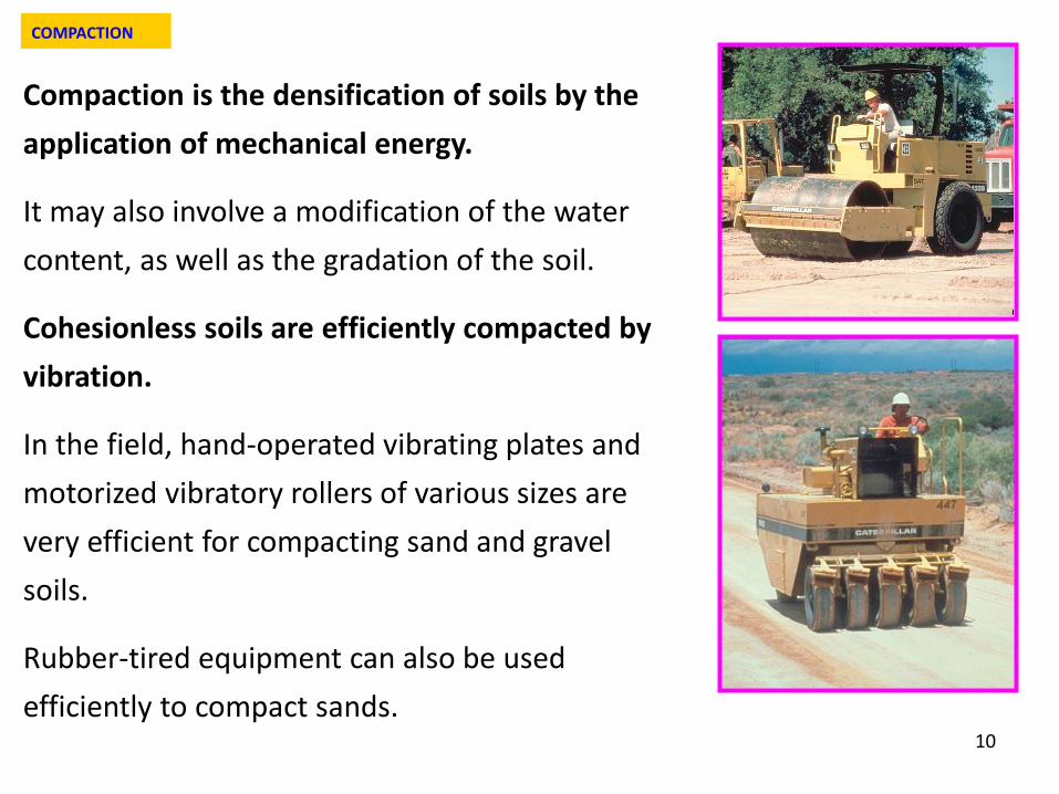
Compaction is the densification of soils by the application of mechanical energy.
It may also involve a modification of the water content, as well as the gradation of the soil.
Cohesionless soils are efficiently compacted by vibration.
In the field, hand-operated vibrating plates and motorized vibratory rollers of various sizes are very efficient for compacting sand and gravel soils.
Rubber-tired equipment can also be used efficiently to compact sands.
COMPACTION
11
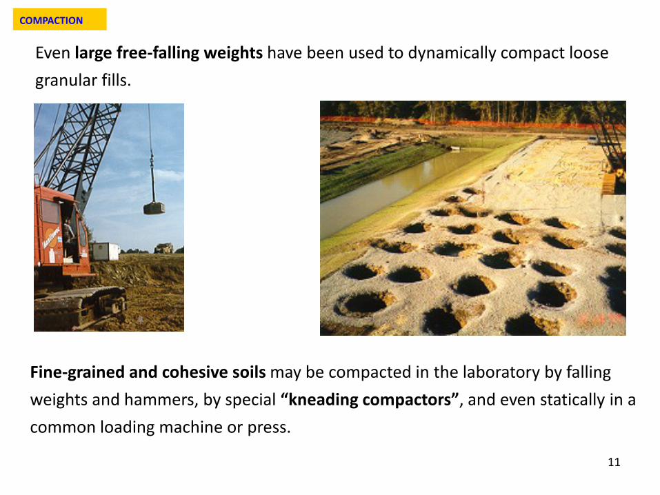
Even large free-falling weights have been used to dynamically compact loose granular fills.
Fine-grained and cohesive soils may be compacted in the laboratory by falling weights and hammers, by special “kneading compactors”, and even statically in a common loading machine or press.
COMPACTION
12
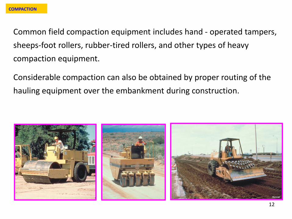
Common field compaction equipment includes hand - operated tampers, sheeps-foot rollers, rubber-tired rollers, and other types of heavy compaction equipment.
Considerable compaction can also be obtained by proper routing of the hauling equipment over the embankment during construction.
COMPACTION
13
Strategy for compacting earth embankment/filling
1 - definition of the in situ conditions (water content, density, depth and thickness of layers etc.)
2- choose of a suitable compaction machine (smooth roller, vibrating roller, rubber-tire equipment, sheeps-foot roller etc)
3 - definition of suitable monitoring procedures (type and number of tests, statistical evaluation etc.)
Previous three points also depend on:
• nature of soil
• geotechnical properties to emphasize
COMPACTION
14
Possible geotechnical properties to emphasize:
(1) permeability
(2) compressibility
(3) swelling
(4) strength
(1) deformability
COMPACTION
15
R. R. Proctor in the early 1930’s was building dams for the old Bureau of Waterworks and Supply in Los Angeles.
He developed the principles of compaction in a series of articles in Engineering News Record (1933).
Proctor carried out a wide experimental plan of laboratory tests for evaluating the influence of water content and compactive effort on soil densification.
In his honour, the standard laboratory compaction test, which he developed, is commonly called Proctor test.
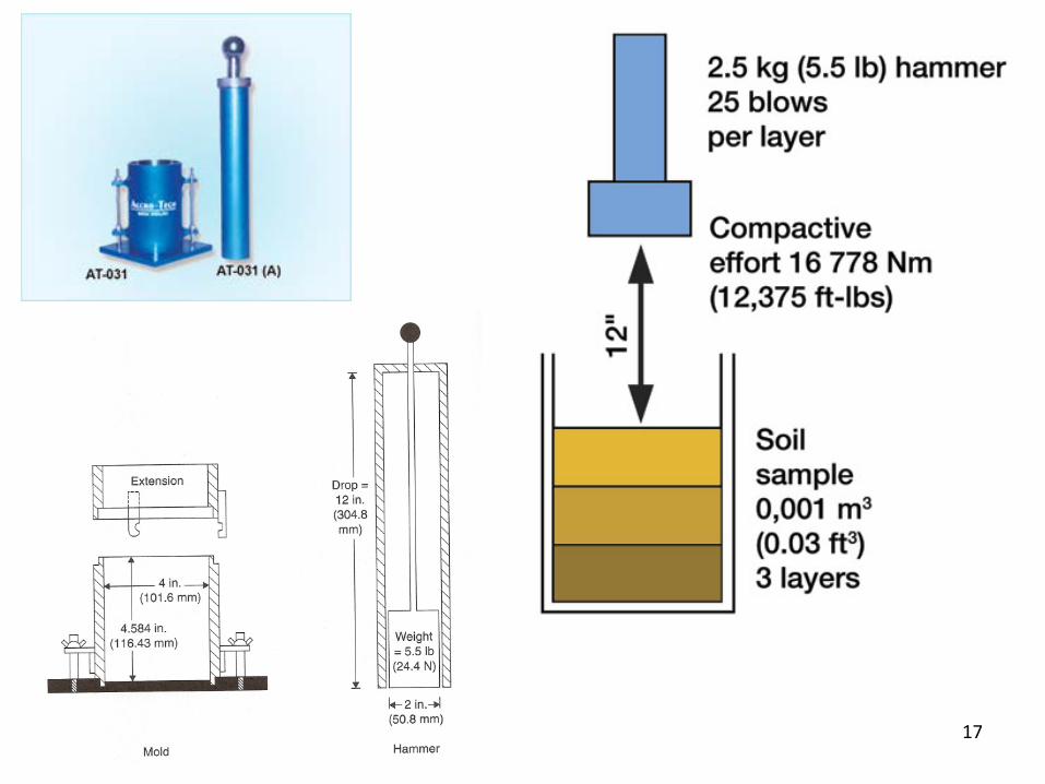
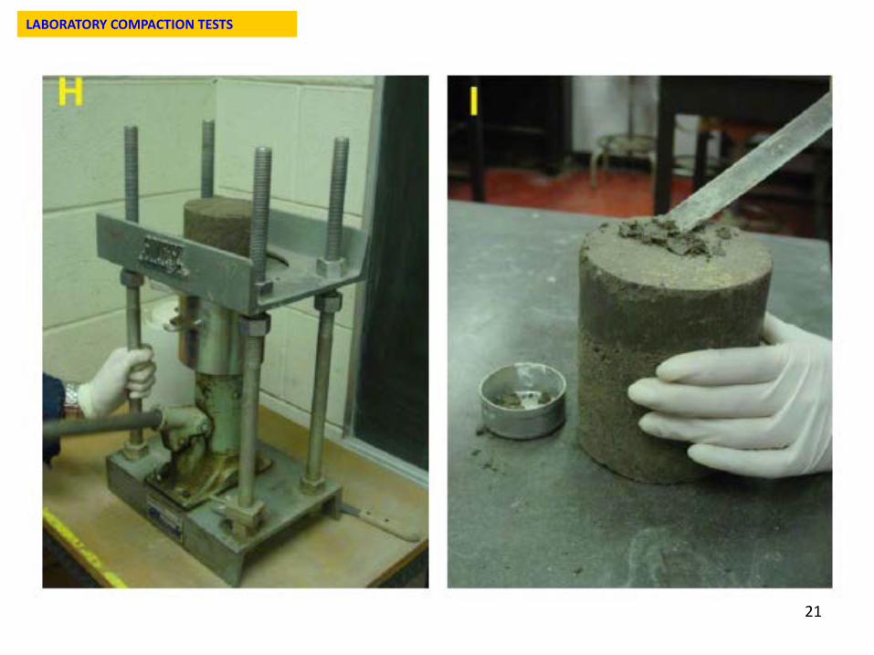
He conceived a test in which soil is put into a cylindric steel mold by 3/5 layers. Each layer is compacted by a hammer falling from a given height.
LABORATORY COMPACTION TESTS
16
In compaction tests we can vary:
(1) water content
(2) method of compaction (Proctor, Kneading, etc.)
(3) energy of compaction
LABORATORY COMPACTION TESTS
Energy E can be modified varying:
(1) weight of hammer
(2) height of fall
(3) number of drop for each layer
(4) thickness of layers.
17
18
LABORATORY COMPACTION TESTS
19
LABORATORY COMPACTION TESTS
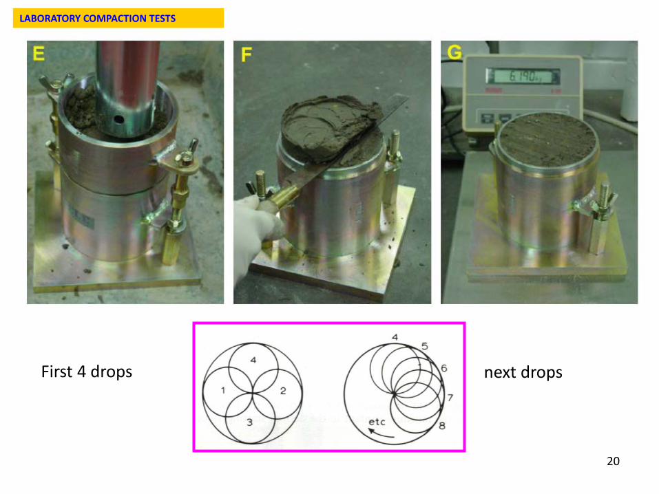
20
First 4 drops next drops
LABORATORY COMPACTION TESTS
21
LABORATORY COMPACTION TESTS
22
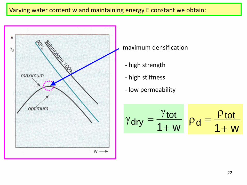
maximum densification
- high strength
- high stiffness
- low permeability
Varying water content w and maintaining energy E constant we obtain:
w1tot
dry +γ
=γw1
totd +
ρ=ρ
23
Compactive effort is a measure of the mechanical energy applied to a soil.
Compactive effort is usually reported in J/m3 [1 J = 1 N m]
In situ compactive effort is the number of passes or “coverages” of the roller of a certain type and weight on a given volume of soil.
In laboratory impact compaction is usually employed.
A hammer is dropped several times on a remoulded soil sample in a mold.
Mass of the hammer, height of drop, number of drops, number of layers of soil, and the volume of the mold are specified.
LABORATORY COMPACTION TESTS
24
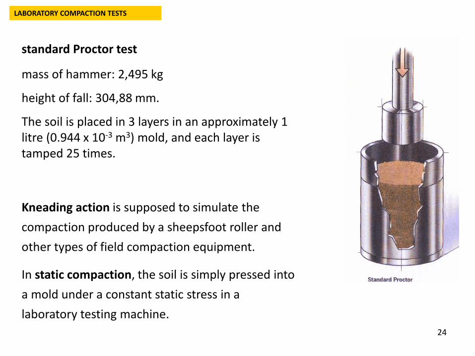
standard Proctor test
mass of hammer: 2,495 kg
height of fall: 304,88 mm.
The soil is placed in 3 layers in an approximately 1 litre (0.944 x 10⁻³ m3) mold, and each layer is tamped 25 times.
Kneading action is supposed to simulate the compaction produced by a sheepsfoot roller and other types of field compaction equipment.
In static compaction, the soil is simply pressed into a mold under a constant static stress in a laboratory testing machine.
LABORATORY COMPACTION TESTS
25
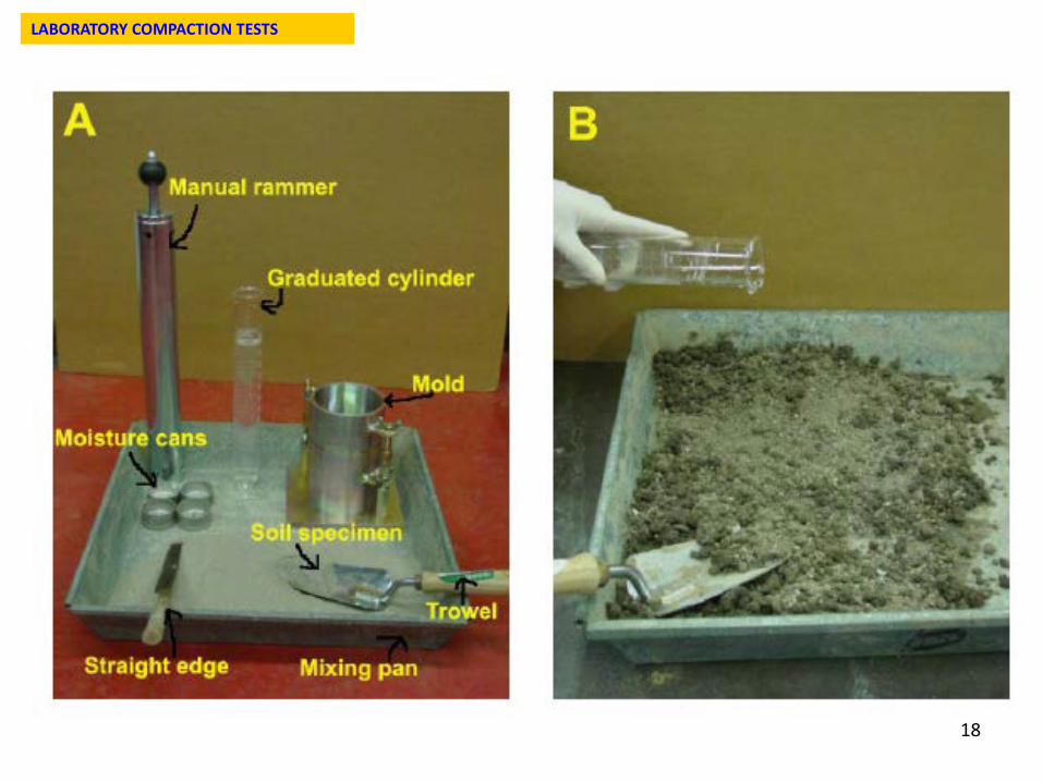
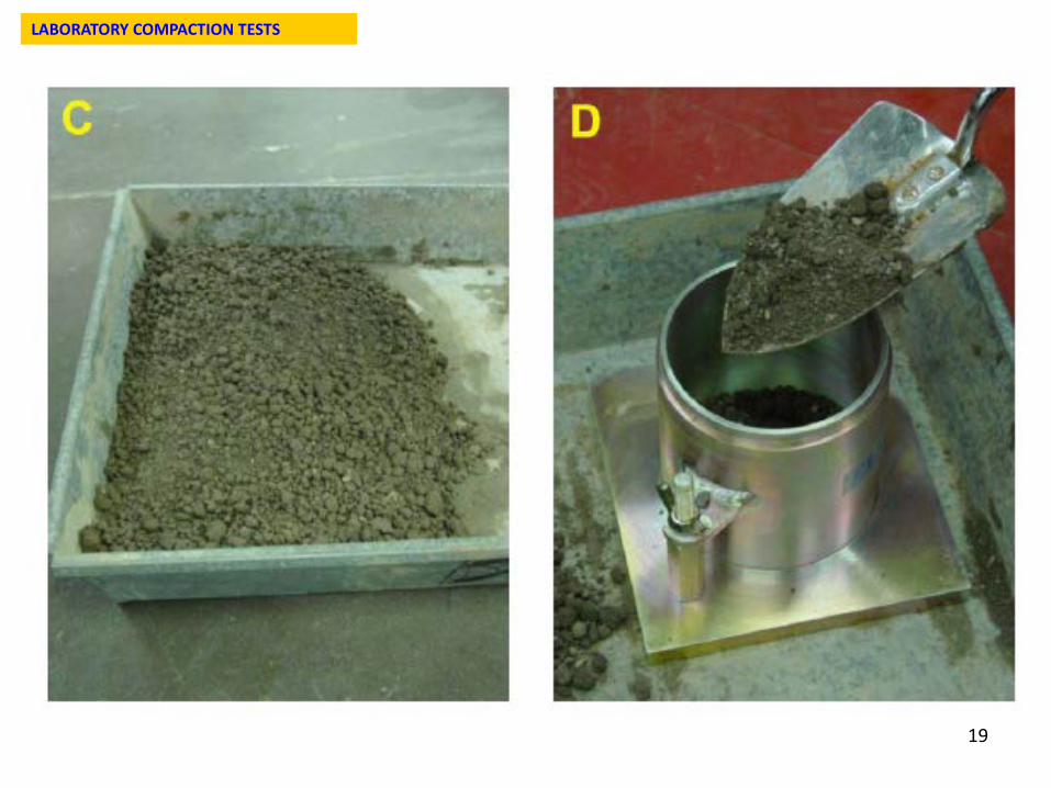
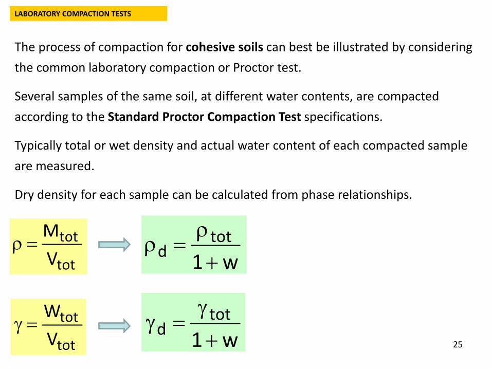
The process of compaction for cohesive soils can best be illustrated by considering the common laboratory compaction or Proctor test.
Several samples of the same soil, at different water contents, are compacted according to the Standard Proctor Compaction Test specifications.
Typically total or wet density and actual water content of each compacted sample are measured.
Dry density for each sample can be calculated from phase relationships.
tot
totVM
=ρ
LABORATORY COMPACTION TESTS
w1tot
d +γ
=γ
w1tot
d +ρ
=ρ
tot
totVW
=γ
26
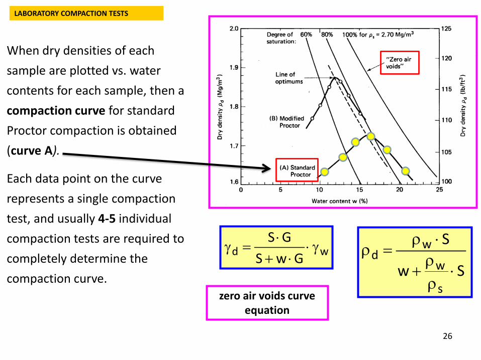
When dry densities of each sample are plotted vs. water contents for each sample, then a compaction curve for standard Proctor compaction is obtained (curve A).
Each data point on the curve represents a single compaction test, and usually 4-5 individual compaction tests are required to completely determine the compaction curve.
wd GwSGS
γ⋅⋅+
⋅=γ
Sw
S
s
w
wd
⋅ρρ
+
⋅ρ=ρ
zero air voids curve equation
LABORATORY COMPACTION TESTS
27
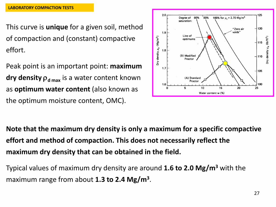
This curve is unique for a given soil, method of compaction and (constant) compactive effort.
Peak point is an important point: maximum dry density ρd max is a water content known as optimum water content (also known as the optimum moisture content, OMC).
Note that the maximum dry density is only a maximum for a specific compactive effort and method of compaction. This does not necessarily reflect the maximum dry density that can be obtained in the field.
Typical values of maximum dry density are around 1.6 to 2.0 Mg/m3 with the maximum range from about 1.3 to 2.4 Mg/m3.
LABORATORY COMPACTION TESTS
28
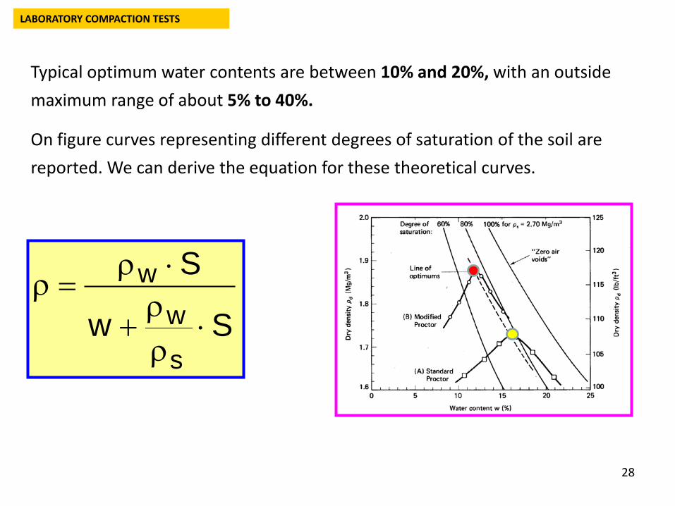
Typical optimum water contents are between 10% and 20%, with an outside maximum range of about 5% to 40%.
On figure curves representing different degrees of saturation of the soil are reported. We can derive the equation for these theoretical curves.
Sw
S
s
ww
⋅ρρ
+
⋅ρ=ρ
LABORATORY COMPACTION TESTS
29
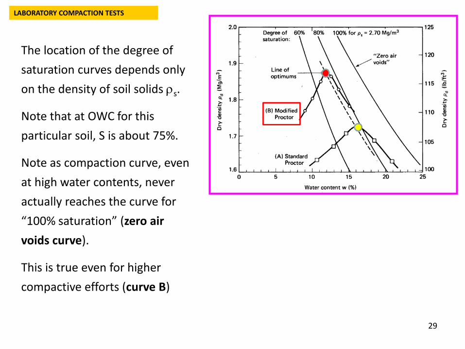
The location of the degree of saturation curves depends only on the density of soil solids ρs.
Note that at OWC for this particular soil, S is about 75%.
Note as compaction curve, even at high water contents, never actually reaches the curve for “100% saturation” (zero air voids curve).
This is true even for higher compactive efforts (curve B)
LABORATORY COMPACTION TESTS
30
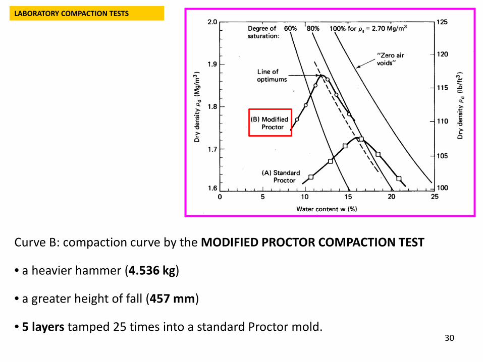
Curve B: compaction curve by the MODIFIED PROCTOR COMPACTION TEST
• a heavier hammer (4.536 kg)
• a greater height of fall (457 mm)
• 5 layers tamped 25 times into a standard Proctor mold.
LABORATORY COMPACTION TESTS
31
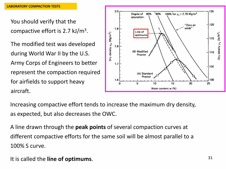
You should verify that the compactive effort is 2.7 kJ/m3.
The modified test was developed during World War II by the U.S. Army Corps of Engineers to better represent the compaction required for airfields to support heavy aircraft.
Increasing compactive effort tends to increase the maximum dry density, as expected, but also decreases the OWC.
A line drawn through the peak points of several compaction curves at different compactive efforts for the same soil will be almost parallel to a 100% S curve.
It is called the line of optimums.
LABORATORY COMPACTION TESTS
32
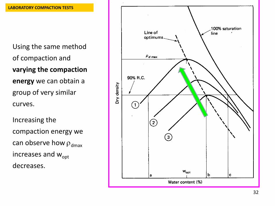
Using the same method of compaction and varying the compaction energy we can obtain a group of very similar curves.
Increasing the compaction energy we can observe how ρdmax
increases and wopt
decreases.
LABORATORY COMPACTION TESTS
33
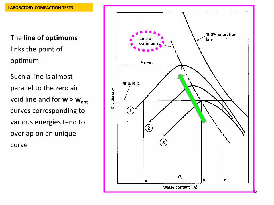
The line of optimums links the point of optimum.
Such a line is almost parallel to the zero air void line and for w > wopt
curves corresponding to various energies tend to overlap on an unique curve
LABORATORY COMPACTION TESTS
34
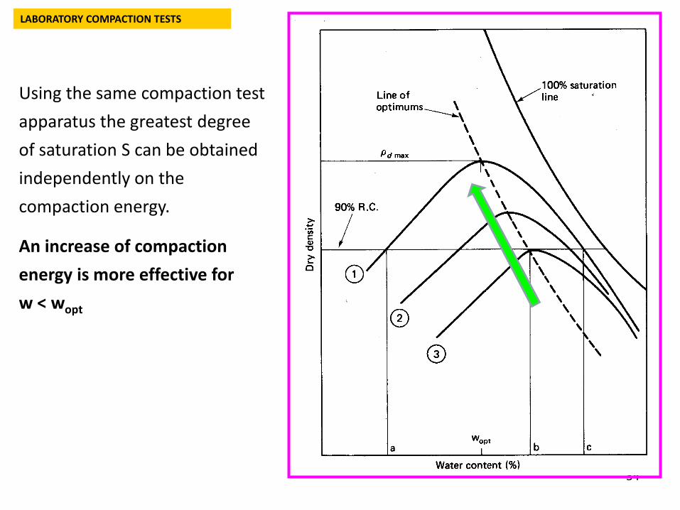
Using the same compaction test apparatus the greatest degree of saturation S can be obtained independently on the compaction energy.
An increase of compaction energy is more effective for w < wopt
LABORATORY COMPACTION TESTS
35
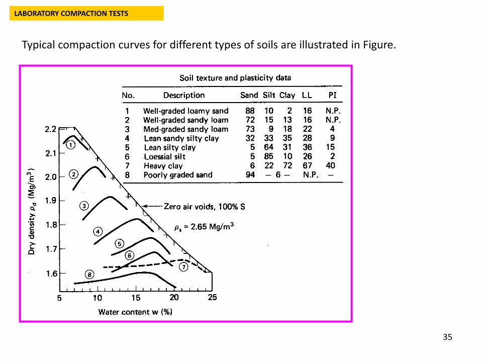
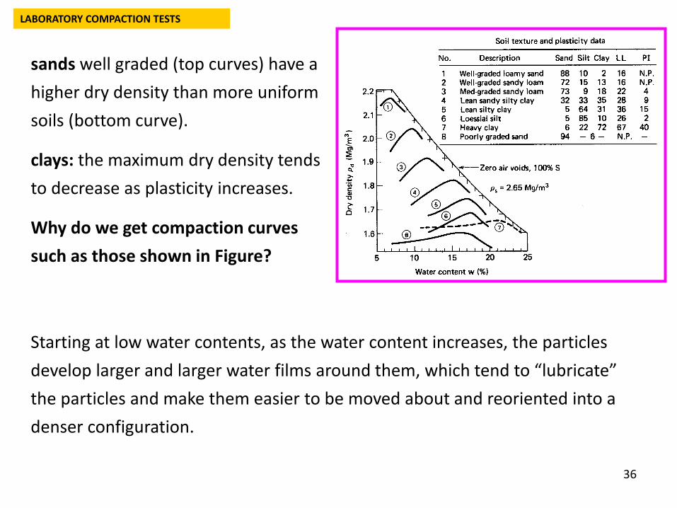
Typical compaction curves for different types of soils are illustrated in Figure.
LABORATORY COMPACTION TESTS
36
sands well graded (top curves) have a higher dry density than more uniform soils (bottom curve).
clays: the maximum dry density tends to decrease as plasticity increases.
Why do we get compaction curves such as those shown in Figure?
Starting at low water contents, as the water content increases, the particles develop larger and larger water films around them, which tend to “lubricate” the particles and make them easier to be moved about and reoriented into a denser configuration.
LABORATORY COMPACTION TESTS
37
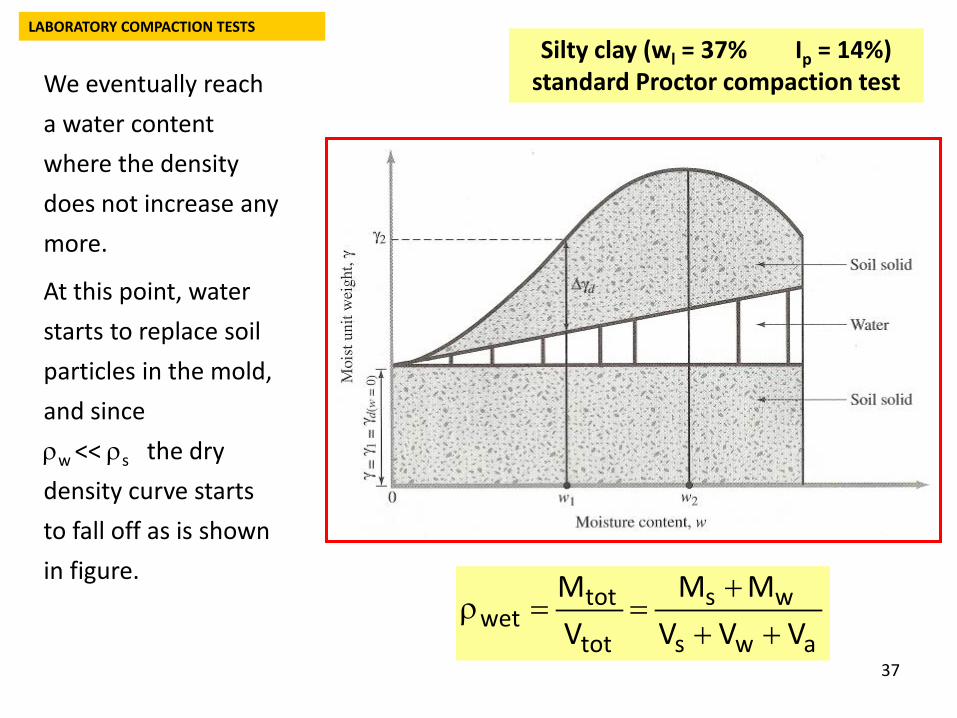
We eventually reach a water content where the density does not increase any more.
At this point, water starts to replace soil particles in the mold, and since ρw << ρs the dry density curve starts to fall off as is shown in figure.
LABORATORY COMPACTION TESTS
aws
ws
tot
totwet VVV
MMVM
+++
==ρ
Silty clay (wl = 37% Ip = 14%) standard Proctor compaction test
38
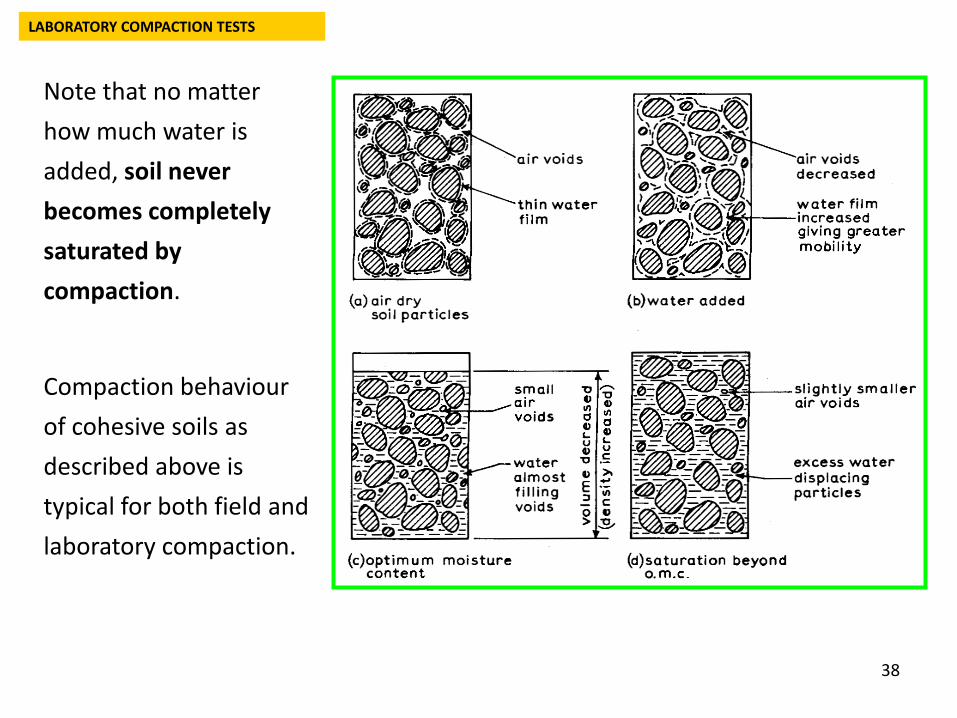
Note that no matter how much water is added, soil never becomes completely saturated by compaction.
Compaction behaviour of cohesive soils as described above is typical for both field and laboratory compaction.
LABORATORY COMPACTION TESTS
39
PROPERTIES AND STRUCTURE OF COMPACTED COHESIVE SOILS
The structure and engineering properties of compacted cohesive soils will depend greatly on the method or type of compaction, the compactive effort applied, the soil type, and on the molding water content.
Usually the water content of compacted soils is referenced to the OWC for a given type of compaction.
Depending on their position, soils are called dry of optimum (w < wopt) near or at optimum, or wet of optimum (w > wopt) .
When they are compacted dry of optimum, the structure of the soils is essentially independent of the type of compaction.
Wet of optimum the type of compaction has a significant effect on the soil structure and thus on the strength, compressibility, etc., of the soil.
40
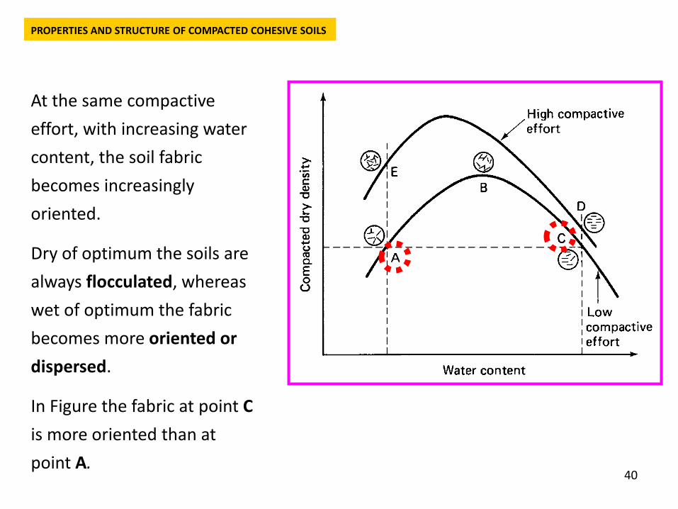
At the same compactive effort, with increasing water content, the soil fabric becomes increasingly oriented.
Dry of optimum the soils are always flocculated, whereas wet of optimum the fabric becomes more oriented or dispersed.
In Figure the fabric at point Cis more oriented than at point A.
PROPERTIES AND STRUCTURE OF COMPACTED COHESIVE SOILS
41
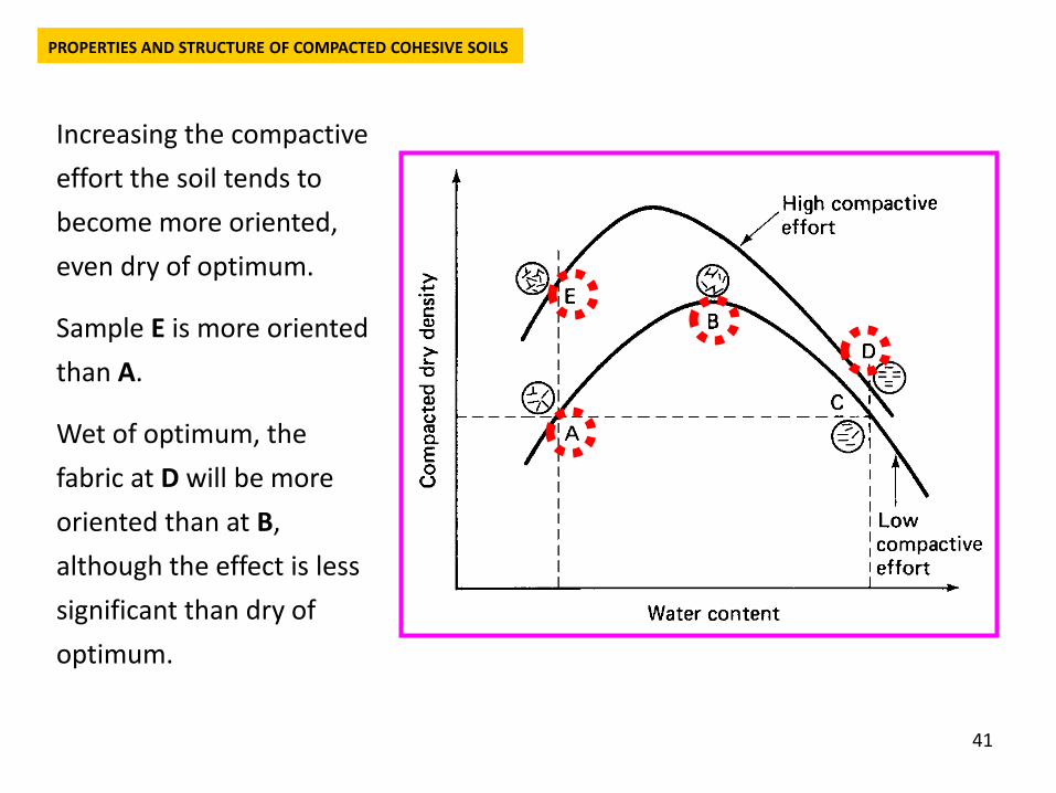
Increasing the compactive effort the soil tends to become more oriented, even dry of optimum.
Sample E is more oriented than A.
Wet of optimum, the fabric at D will be more oriented than at B, although the effect is less significant than dry of optimum.
PROPERTIES AND STRUCTURE OF COMPACTED COHESIVE SOILS
42
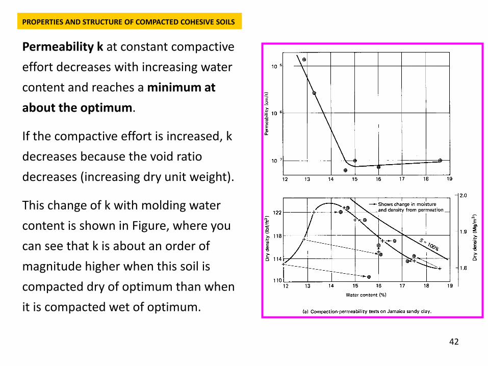
Permeability k at constant compactive effort decreases with increasing water content and reaches a minimum at about the optimum.
If the compactive effort is increased, k decreases because the void ratio decreases (increasing dry unit weight).
This change of k with molding water content is shown in Figure, where you can see that k is about an order of magnitude higher when this soil is compacted dry of optimum than when it is compacted wet of optimum.
PROPERTIES AND STRUCTURE OF COMPACTED COHESIVE SOILS
43
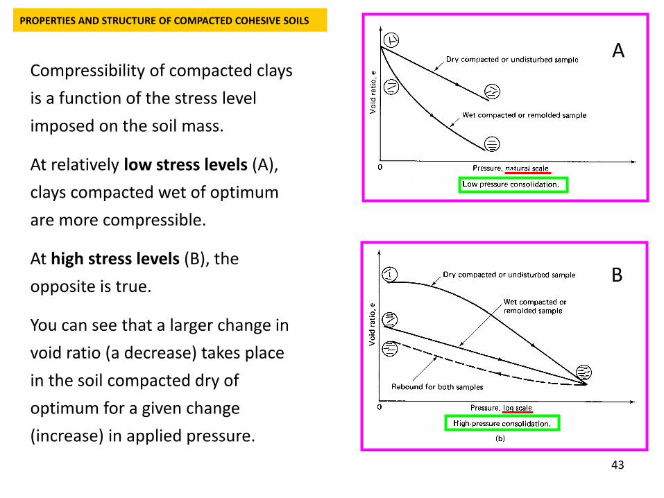
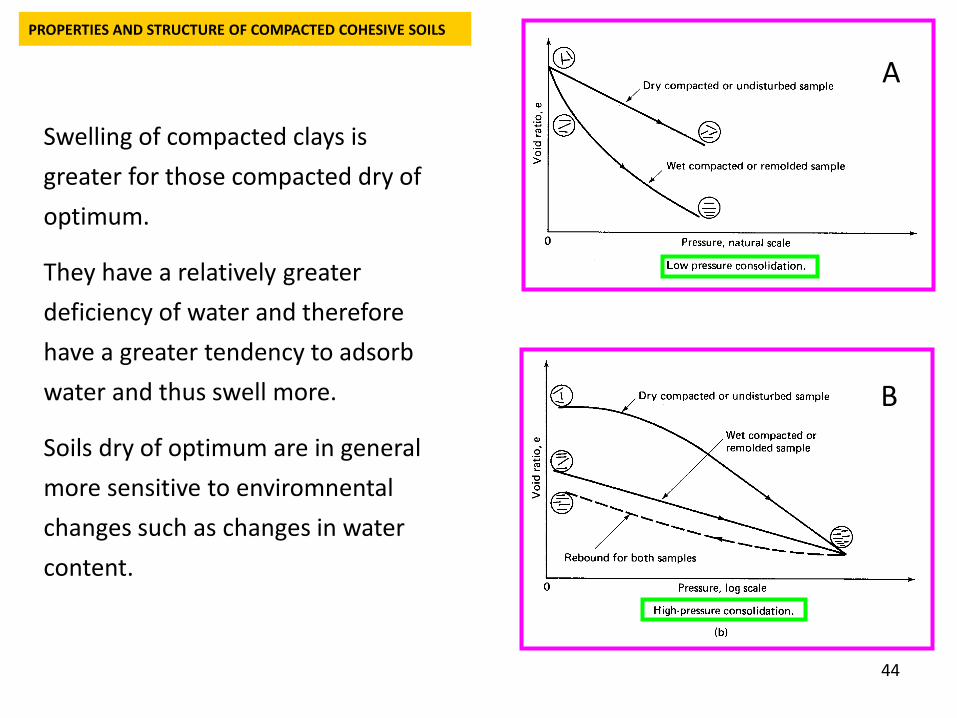
Compressibility of compacted clays is a function of the stress level imposed on the soil mass.
At relatively low stress levels (A), clays compacted wet of optimum are more compressible.
At high stress levels (B), the opposite is true.
You can see that a larger change in void ratio (a decrease) takes place in the soil compacted dry of optimum for a given change (increase) in applied pressure.
PROPERTIES AND STRUCTURE OF COMPACTED COHESIVE SOILS
A
B
44
Swelling of compacted clays is greater for those compacted dry of optimum.
They have a relatively greater deficiency of water and therefore have a greater tendency to adsorb water and thus swell more.
Soils dry of optimum are in general more sensitive to enviromnental changes such as changes in water content.
PROPERTIES AND STRUCTURE OF COMPACTED COHESIVE SOILS
A
B
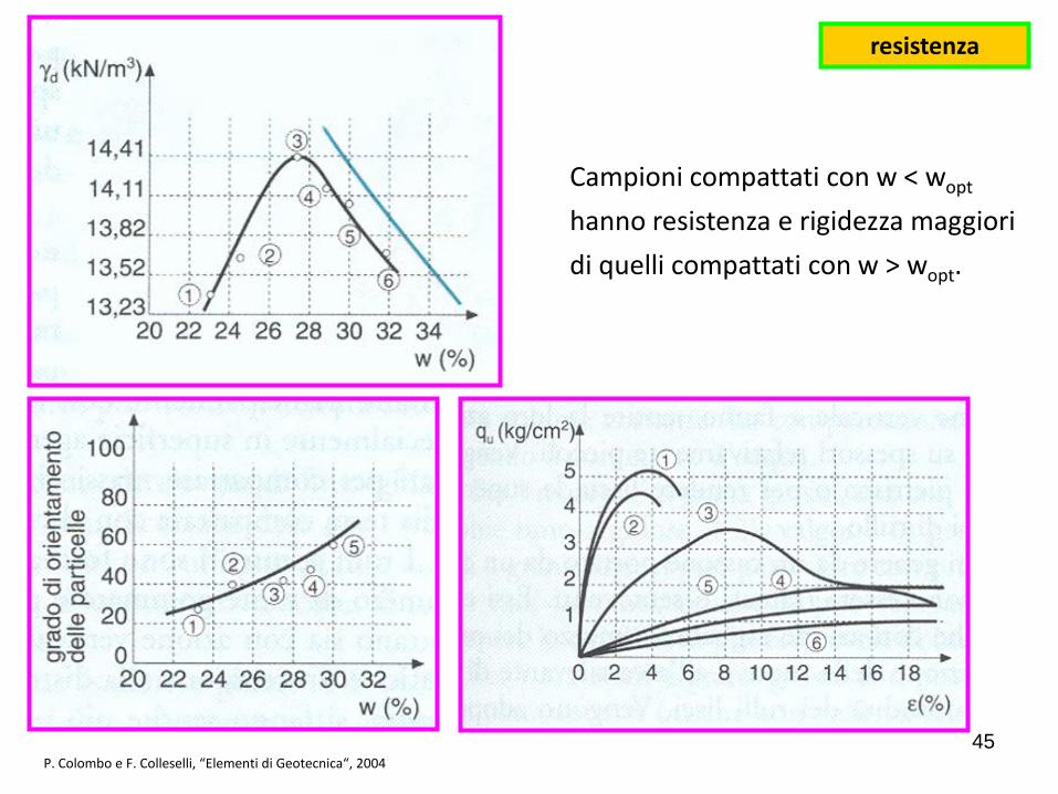
Campioni compattati con w < wopt
hanno resistenza e rigidezza maggiori di quelli compattati con w > wopt.
P. Colombo e F. Colleselli, “Elementi di Geotecnica“, 2004
resistenza
45
46
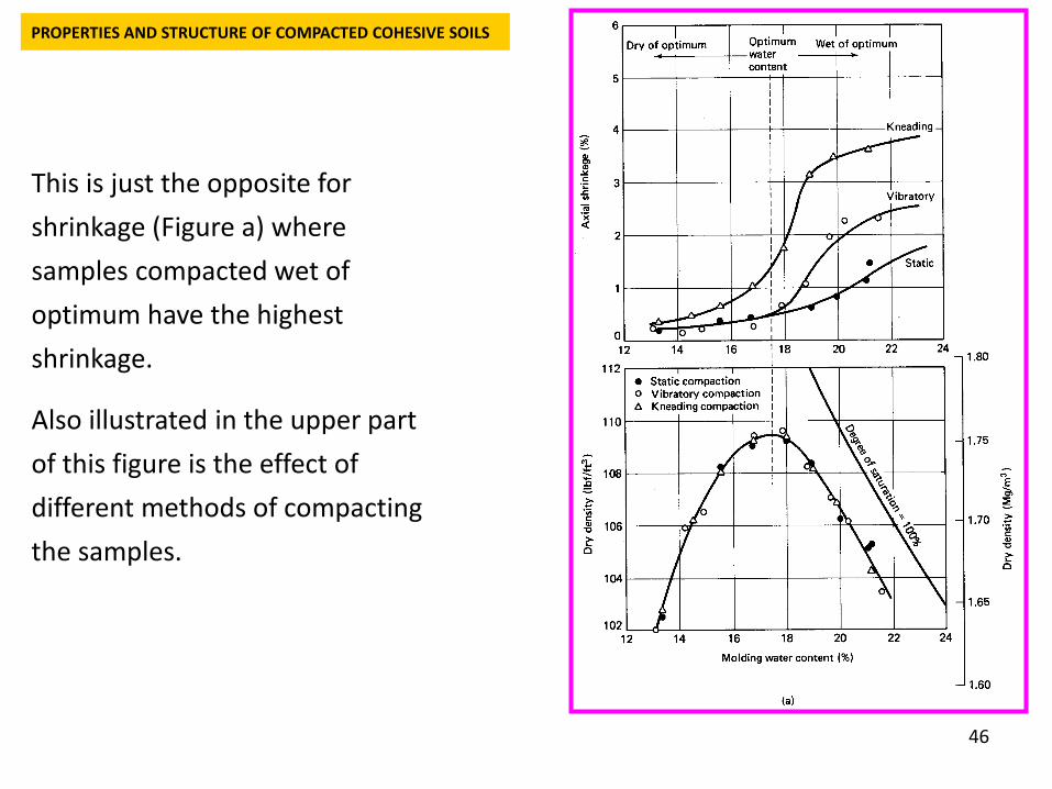
This is just the opposite for shrinkage (Figure a) where samples compacted wet of optimum have the highest shrinkage.
Also illustrated in the upper part of this figure is the effect of different methods of compacting the samples.
PROPERTIES AND STRUCTURE OF COMPACTED COHESIVE SOILS
47
PROPERTIES AND STRUCTURE OF COMPACTED COHESIVE SOILS
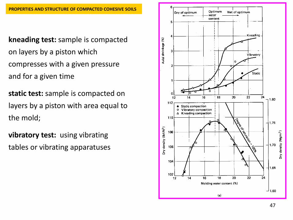
kneading test: sample is compacted on layers by a piston which compresses with a given pressure and for a given time
static test: sample is compacted on layers by a piston with area equal to the mold;
vibratory test: using vibrating tables or vibrating apparatuses
48
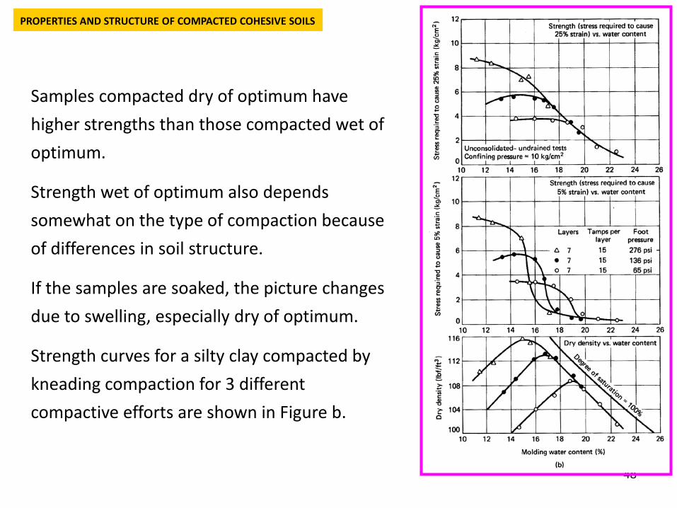
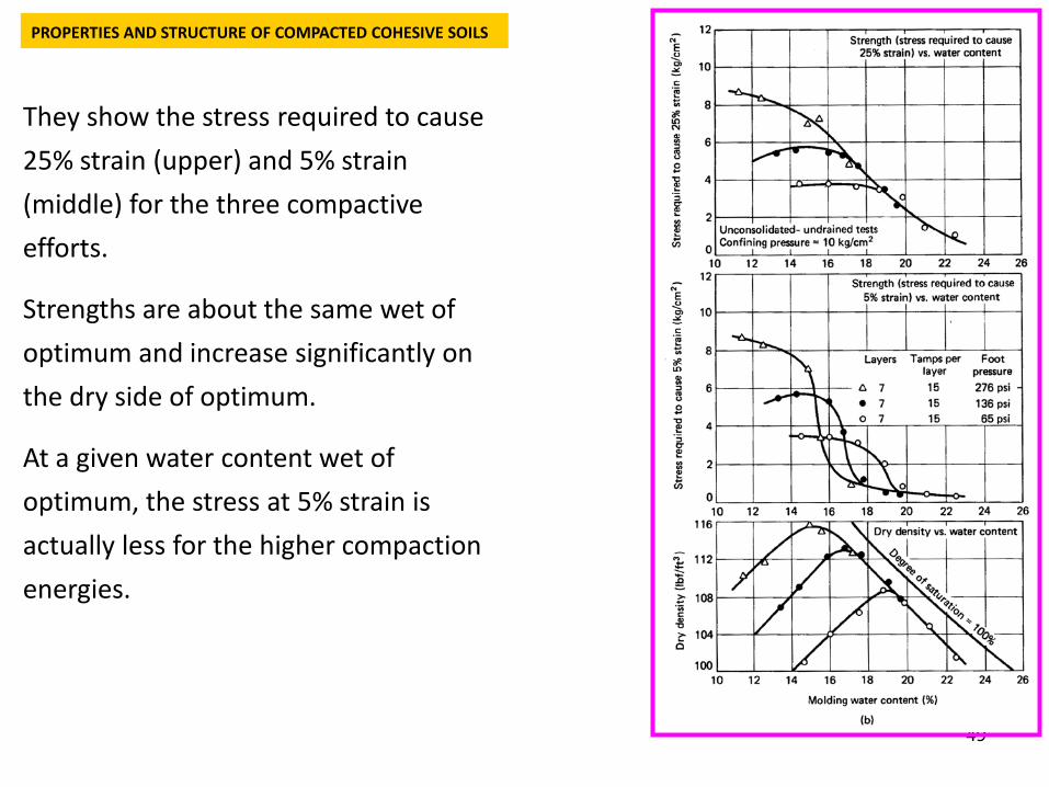
Samples compacted dry of optimum have higher strengths than those compacted wet of optimum.
Strength wet of optimum also depends somewhat on the type of compaction because of differences in soil structure.
If the samples are soaked, the picture changes due to swelling, especially dry of optimum.
Strength curves for a silty clay compacted by kneading compaction for 3 different compactive efforts are shown in Figure b.
PROPERTIES AND STRUCTURE OF COMPACTED COHESIVE SOILS
49
They show the stress required to cause 25% strain (upper) and 5% strain (middle) for the three compactive efforts.
Strengths are about the same wet of optimum and increase significantly on the dry side of optimum.
At a given water content wet of optimum, the stress at 5% strain is actually less for the higher compaction energies.
PROPERTIES AND STRUCTURE OF COMPACTED COHESIVE SOILS
50
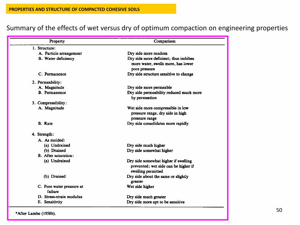
Summary of the effects of wet versus dry of optimum compaction on engineering properties
PROPERTIES AND STRUCTURE OF COMPACTED COHESIVE SOILS
51
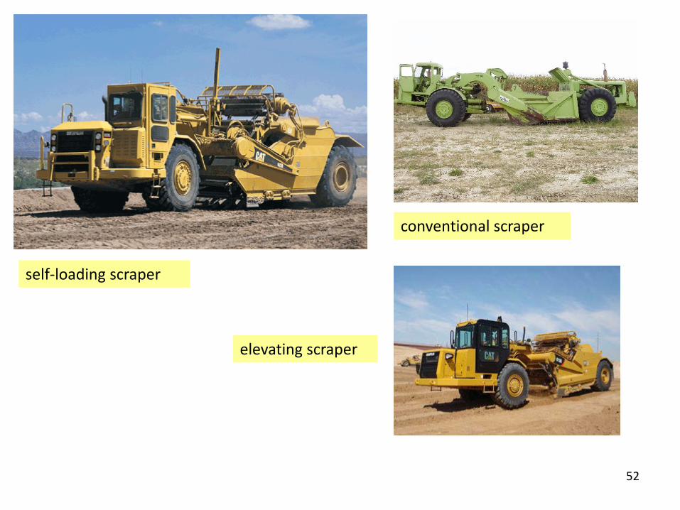
Soil to be used in a compacted fill is excavated from a borrow area. Power shovels, draglines and self-propelled scrapers or “pans” are used to excavate the borrow material.
A self-loading scraper and an elevating scraper are shown in the next slide.
Sometimes “dozers” are necessary to help load the scraper.
Scrapers may cut through layers of different materials, allowing several grain sizes to be mixed, for example.
The power shovel mixes the soil by digging along a vertical surface, whereas the scraper mixes the soil by cutting across a sloping surface where different layers may be exposed.
The borrow area may be on site or several kilometres away.
FIELD COMPACTION EQUIPMENT AND PROCEDURES
52
self-loading scraper
conventional scraper
elevating scraper
53
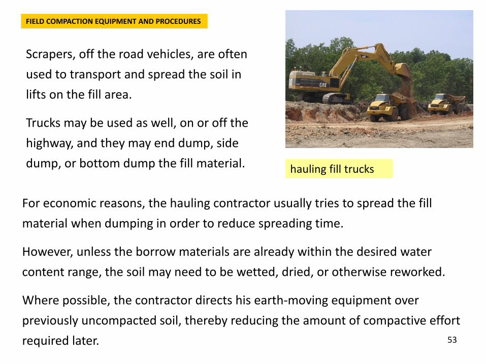
Scrapers, off the road vehicles, are often used to transport and spread the soil in lifts on the fill area.
Trucks may be used as well, on or off the highway, and they may end dump, side dump, or bottom dump the fill material.
FIELD COMPACTION EQUIPMENT AND PROCEDURES
hauling fill trucks
For economic reasons, the hauling contractor usually tries to spread the fill material when dumping in order to reduce spreading time.
However, unless the borrow materials are already within the desired water content range, the soil may need to be wetted, dried, or otherwise reworked.
Where possible, the contractor directs his earth-moving equipment over previously uncompacted soil, thereby reducing the amount of compactive effort required later.
54
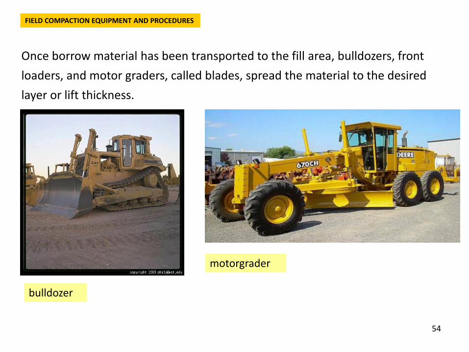
Once borrow material has been transported to the fill area, bulldozers, front loaders, and motor graders, called blades, spread the material to the desired layer or lift thickness.
FIELD COMPACTION EQUIPMENT AND PROCEDURES
bulldozer
motorgrader
55
Lift thickness may range from 150 to 500 mm or so, depending on the size and type of compaction equipment and on maximum grain size of the fill.
The kind of compacting equipment or rollers used on a job will depend on the type of soil to be compacted. Equipment is available to apply pressure, impact, vibration, and kneading.
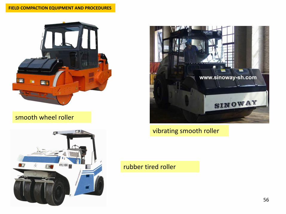
A smooth wheel, or drum, roller supplies 100% coverage under the wheel, with ground contact pressures up to 380 kPa and may be used on all soil types except rocky soils.
The most common use for large smooth wheel rollers is for proofrolling subgrades and compacting asphalt pavements.
The pneumatic, or rubber-tired, roller has about 80% coverage (80% of the total area is covered by tires) and tire pressures may be up to about 700 kPa.
FIELD COMPACTION EQUIPMENT AND PROCEDURES
56
FIELD COMPACTION EQUIPMENT AND PROCEDURES
smooth wheel roller
vibrating smooth roller
rubber tired roller
57
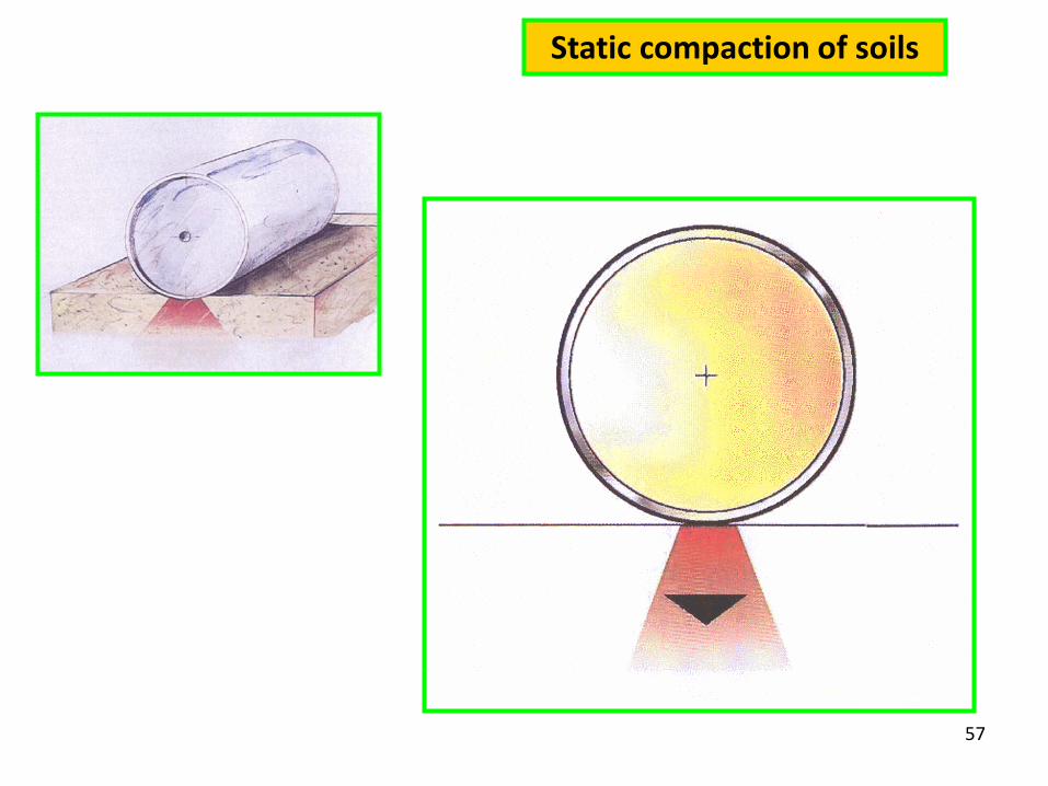
Static compaction of soils
58
A heavily loaded wagon with several rows of four to six closely spaced tires is self-propelled or towed over the soil to be compacted.
Like the smooth wheel roller, the rubber-tired roller may be used for both granular and cohesive highway fills, as well as for earth dam construction.
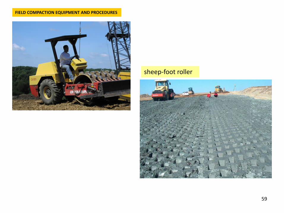
Probably the first roller developed and perhaps the most common type of compactor used today is the sheeps-foot roller.
This roller, as its name implies, has many round or rectangular shaped protrusions or “feet” attached to a steel drum.
The area of these protrusions ranges from 30 to 80 cm2.
Because of the 8% to 12% coverage, very high contact pressures are possible, ranging from 1400 to 7000 kPa depending on the drum size and whether the drum is filled with water. The drums come in several diameters.
FIELD COMPACTION EQUIPMENT AND PROCEDURES
59
FIELD COMPACTION EQUIPMENT AND PROCEDURES
sheep-foot roller
60
Surprisingly enough, a “4 by 4” (which means 4 ft long and 4 ft in diameter) roller provides a higher strength compacted fill in clay soils than a heavier, higher pressure “5 by 5” roller because there is less kneading or shearing action with the “4 by 4” than the “5 by 5” roller, which produces a different soil structure.
Sheepsfoot rollers are usually towed in tandem by crawler tractors or are self-propelled.
The sheepsfoot roller starts compacting the soil below the bottom of the foot (projecting about 150 to 250 mm from the drum) and works its way up the lift as the number of passes increases.
Eventually the roller “walks out” of the fill as the upper part of the lift is compacted. The sheepsfoot roller is best suited for cohesive soils.
FIELD COMPACTION EQUIPMENT AND PROCEDURES
61
Other rollers with protrusions have also been developed to obtain high contact pressures for better crushing, kneading, and compacting of a rather wide variety of soils.
These rollers can either be towed or selfpropelled.
Tamping foot rollers have approximately 40% coverage and generate high contact pressures from 1400 to 8400 kPa, depending on the size of the roller and whether the drum is filled for added weight.
The special hinged feet of the tamping foot roller apply a kneading action to the soil.
These rollers compact similarly to the sheepsfoot in that the roller eventually “walks out” of a wellcompacted lift.
FIELD COMPACTION EQUIPMENT AND PROCEDURES
62
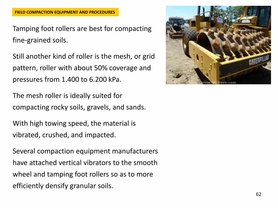
Tamping foot rollers are best for compacting fine-grained soils.
Still another kind of roller is the mesh, or grid pattern, roller with about 50% coverage and pressures from 1.400 to 6.200 kPa.
The mesh roller is ideally suited for compacting rocky soils, gravels, and sands.
With high towing speed, the material is vibrated, crushed, and impacted.
Several compaction equipment manufacturers have attached vertical vibrators to the smooth wheel and tamping foot rollers so as to more efficiently densify granular soils.
FIELD COMPACTION EQUIPMENT AND PROCEDURES
63
FIELD COMPACTION EQUIPMENT AND PROCEDURES
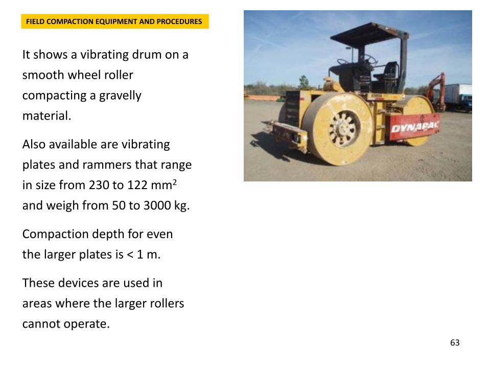
It shows a vibrating drum on a smooth wheel roller compacting a gravelly material.
Also available are vibrating plates and rammers that range in size from 230 to 122 mm2
and weigh from 50 to 3000 kg.
Compaction depth for even the larger plates is < 1 m.
These devices are used in areas where the larger rollers cannot operate.
64
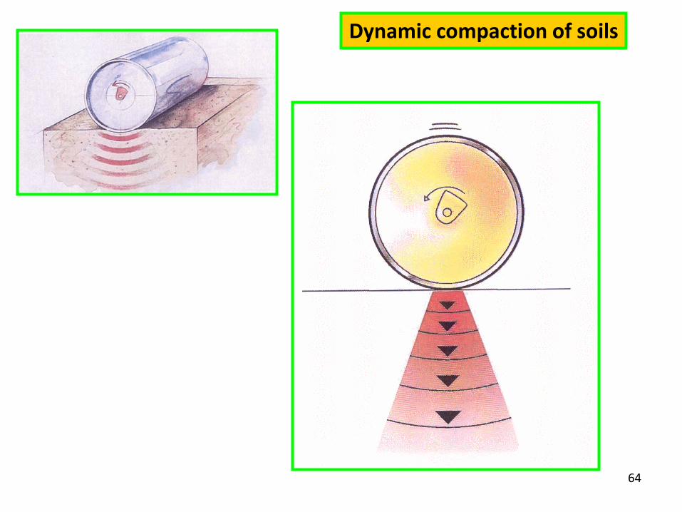
Dynamic compaction of soils
EG - SOIL COMPACTION 65
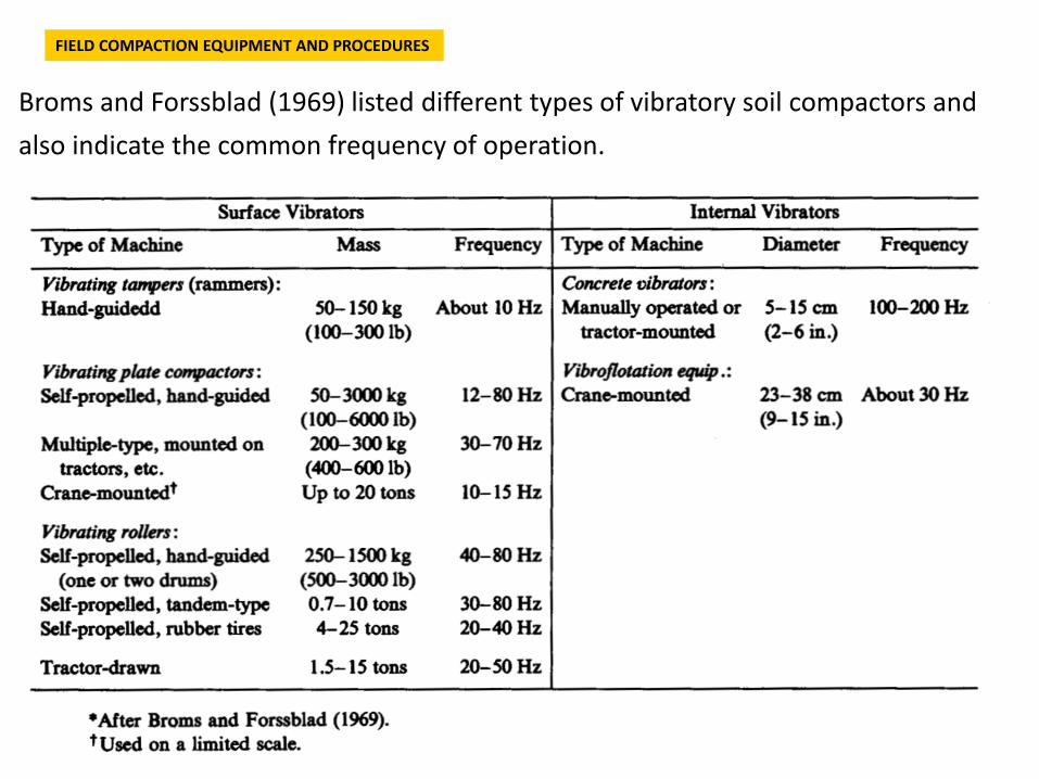
Broms and Forssblad (1969) listed different types of vibratory soil compactors and also indicate the common frequency of operation.
FIELD COMPACTION EQUIPMENT AND PROCEDURES
EG - SOIL COMPACTION 66
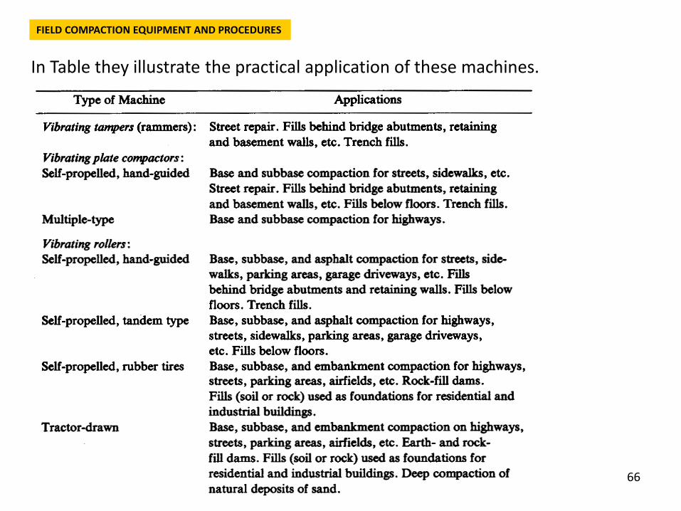
In Table they illustrate the practical application of these machines.
FIELD COMPACTION EQUIPMENT AND PROCEDURES
67
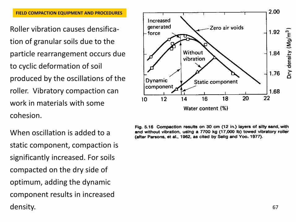
Roller vibration causes densifica-tion of granular soils due to the particle rearrangement occurs due to cyclic deformation of soil produced by the oscillations of the roller. Vibratory compaction can work in materials with some cohesion.
When oscillation is added to a static component, compaction is significantly increased. For soils compacted on the dry side of optimum, adding the dynamic component results in increased density.
FIELD COMPACTION EQUIPMENT AND PROCEDURES
68
There are many variables which control the vibratory compaction or densification of soils. Some are compactor dependent and some depend on the soil being compacted. The list of variables would include:
Characteristics of the compactor: Mass, size Operating frequency and frequency range
Characteristics of the soil: Initial density Grain size and shape Water content
Construction procedures: Number of passes of the roller Lift thickness Frequency of operation of vibrator Towing speed
FIELD COMPACTION EQUIPMENT AND PROCEDURES
69
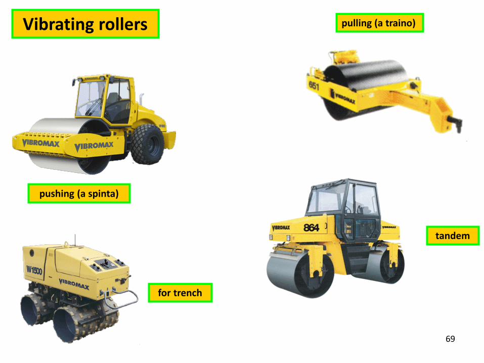
Vibrating rollers
pushing (a spinta)
pulling (a traino)
tandem
for trench
70
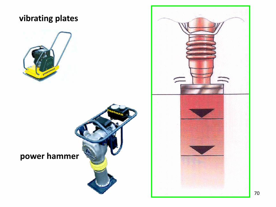
vibrating plates
power hammer
71
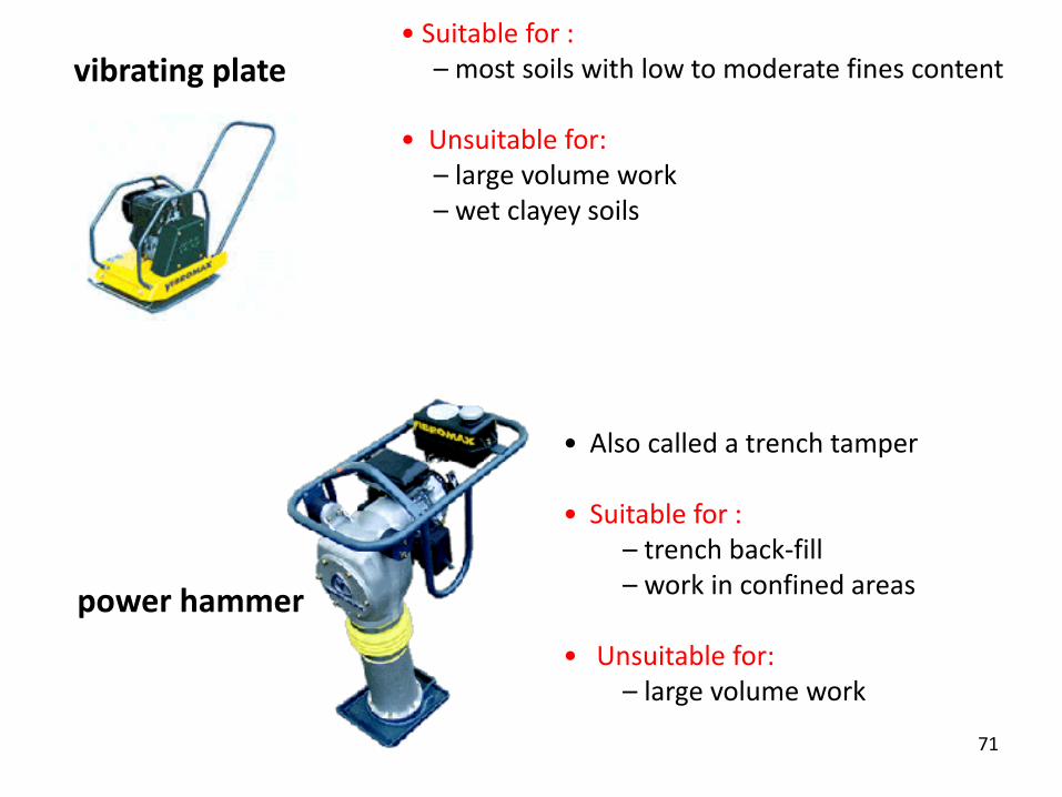
vibrating plate
power hammer
• Suitable for :– most soils with low to moderate fines content
• Unsuitable for:– large volume work– wet clayey soils
• Also called a trench tamper
• Suitable for :– trench back-fill – work in confined areas
• Unsuitable for:– large volume work
72
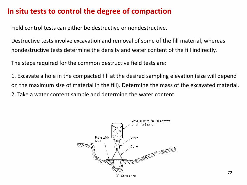
Field control tests can either be destructive or nondestructive.
Destructive tests involve excavation and removal of some of the fill material, whereas nondestructive tests determine the density and water content of the fill indirectly.
The steps required for the common destructive field tests are:
1. Excavate a hole in the compacted fill at the desired sampling elevation (size will depend on the maximum size of material in the fill). Determine the mass of the excavated material. 2. Take a water content sample and determine the water content.
In situ tests to control the degree of compaction
73
FIELD COMPACTION CONTROL AND SPECIFICATIONS
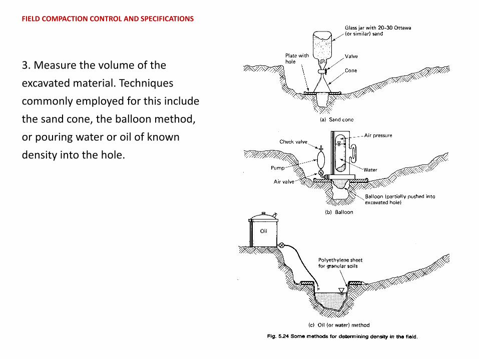
3. Measure the volume of the excavated material. Techniques commonly employed for this include the sand cone, the balloon method, or pouring water or oil of known density into the hole.
74
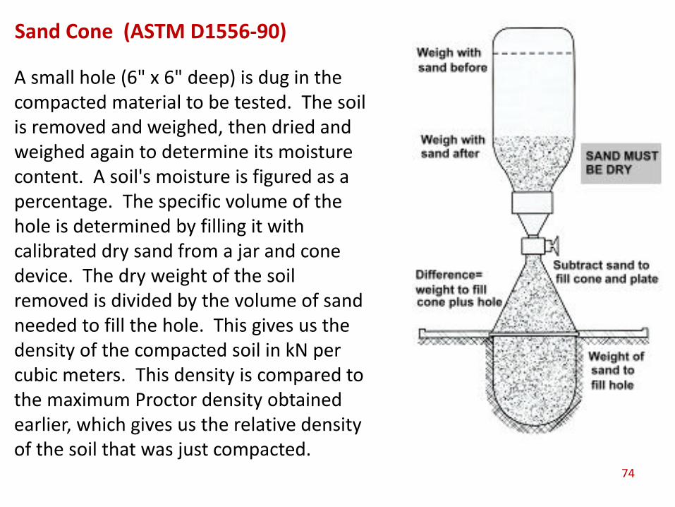
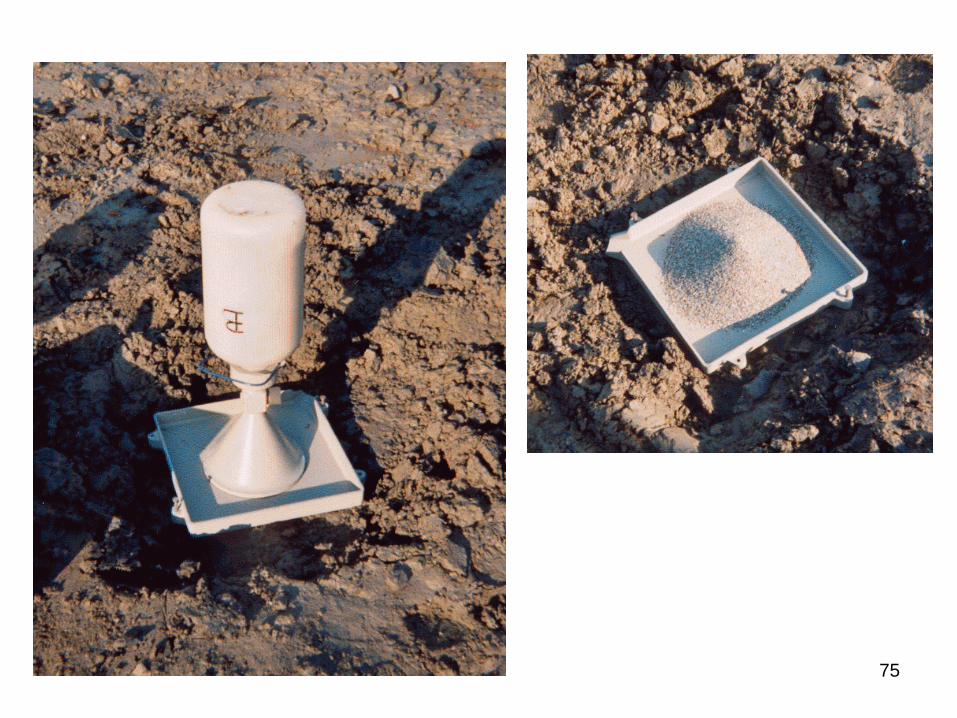
Sand Cone (ASTM D1556-90)
A small hole (6" x 6" deep) is dug in the compacted material to be tested. The soil is removed and weighed, then dried and weighed again to determine its moisture content. A soil's moisture is figured as a percentage. The specific volume of the hole is determined by filling it with calibrated dry sand from a jar and cone device. The dry weight of the soil removed is divided by the volume of sand needed to fill the hole. This gives us the density of the compacted soil in kN per cubic meters. This density is compared to the maximum Proctor density obtained earlier, which gives us the relative density of the soil that was just compacted.
75