Embed Size (px)
Citation preview
Compaq Armada M300Series of Personal ComputersMaintenance and Service Guide

Armada M300 Series of Personal Computers
DOCUMENTATION SURVEYDoes the Maintenance and Service Guide contain all needed information? � Yes � No
If not, what additional information would you like to see in the guide?
Is the guide easy to use? � Yes � No If not, please explain:
Is the artwork easy to interpret? � Yes � No If not, please explain:
What information in the guide do you use most frequently?
What information do you use least?
How often do you refer to the Maintenance and Service Guide?
In what form would you prefer to receive information? (Rank 1 to 5, with 1 representing the most preferred.)Maintenance and Service Guide on CD-ROM
Maintenance and Service Guide on Compaq Web site
Maintenance and Service Guide on QuickFind
Printed Maintenance and Service Guide
A combination of the above (please specify)
How do you receive Maintenance and Service Guides?
Is the guide available in a timely manner (when you need it)? � Yes � No If not, please explain:
Are sufficient quantities of the Maintenance and Service Guide available? � Yes � No If not, please explain:
Additional Documentation Comments:
Name: Phone:
Job Title: Company:
Address:
City: State: Zip:
Notice 2000 Compaq Computer Corporation.COMPAQ, the Compaq logo, and ARMADA Registered in U. S. Patent and Trademark Office
Microsoft, Windows, Windows NT, are registered trademarks of Microsoft Corporation in the United Statesand/or other countries. Intel and Pentium are registered trademarks of Intel Corporation in the United Statesand other countries.
All other product names mentioned herein may be trademarks or registered trademarks of their respectivecompanies.
Compaq shall not be liable for technical or editorial errors or omissions containedherein. The information in this document is subject to change without notice and isprovided “as is” without warranty of any kind. The entire risk arising out of theuse of this information remains with the recipient. In no event shall Compaq beliable for any direct, consequential, incidental, special, punitive, or other damageswhatsoever (including without limitation, damages for loss of business profits,business interruption, or loss of business information), even if Compaq has beenadvised of the possibility of such damages. The limited warranties for Compaqproducts are exclusively set forth in the documentation accompanying suchproducts. Nothing herein should be construed as constituting a further oradditional warranty.
MAINTENANCE AND SERVICE GUIDE
Compaq Armada M300 Series of Personal Computers
Second Edition February 2000First Edition July 1999
Published in the U.S.A., U.K., Singapore, and Taiwan.
Documentation Part Number 113732-002Spare Part Number 158339-001
ContentsArmada M300 Maintenance and Service Guide iii
CONTENTS
prefaceUSING THIS GUIDE ...........................................................................................................................................VII
chapter 1PRODUCT DESCRIPTION
1.1 Computer Features and Models......................................................................................................1-1Models ...........................................................................................................................................1-2Features .........................................................................................................................................1-4Intelligent Manageability ..............................................................................................................1-5Accessing the Web Agent.............................................................................................................1-5Asset Management ........................................................................................................................1-5Fault Management.........................................................................................................................1-6Fault Management Alerts..............................................................................................................1-6Security Management ...................................................................................................................1-6Configuration Management ..........................................................................................................1-7Managing Power ...........................................................................................................................1-7Accessing Power Management.....................................................................................................1-7Power Management Levels...........................................................................................................1-7
1.2 Computer External Components ....................................................................................................1-81.3 Design Overview.........................................................................................................................1-15
System Board ..............................................................................................................................1-15
chapter 2TROUBLESHOOTING
2.1 Preliminary Steps ............................................................................................................................2-22.2 Clearing Passwords.........................................................................................................................2-32.3 Power-On Self-Test (POST)...........................................................................................................2-32.4 POST Error Messages.....................................................................................................................2-42.5 Compaq Utilities .............................................................................................................................2-62.6 Troubleshooting Without Diagnostics ..........................................................................................2-12
Before Replacing Parts................................................................................................................2-12Obtaining Update Information with Info messenger..................................................................2-12Checklist for Solving Problems ..................................................................................................2-13
chapter 3ILLUSTRATED PARTS CATALOG
3.1 Serial Number Location..................................................................................................................3-13.2 Computer Major System Components ...........................................................................................3-23.3 Miscellaneous Plastic Kit Components..........................................................................................3-43.4 Mass Storage Devices.....................................................................................................................3-53.5 Miscellaneous..................................................................................................................................3-6
iv ContentsArmada M300 Maintenance and Service Guide
chapter 4REMOVAL AND REPLACEMENT PRELIMINARIES
4.1 Tools Required................................................................................................................................1-14.2 Service Considerations....................................................................................................................1-1
Plastic Parts ...................................................................................................................................4-1Cables and Connectors..................................................................................................................4-2
4.3 Preventing Damage to Removable Drives .....................................................................................1-24.4 Preventing Electrostatic Damage....................................................................................................1-3
Packaging and Transporting Precautions......................................................................................4-3Workstation Precautions ...............................................................................................................4-4Grounding Equipmemt amd Methods ..........................................................................................4-5Electrostatic Voltage Levels and Protective Matherials...............................................................4-6
chapter 5REMOVAL AND REPLACEMENT PROCEDURES
5.1 Serial Number .................................................................................................................................5-15.2 Disassembly Reference Chart.........................................................................................................5-25.3 Disconnecting the Computer from the Mobile Expansion Unit ....................................................5-35.4 Disconnecting the Computer ..........................................................................................................5-45.5 Preparing the Computer for Disassembly ......................................................................................5-55.6 Battery Packs...................................................................................................................................5-6
Removing the Battery Pack...........................................................................................................5-6Replacing the Battery Pack...........................................................................................................5-7
5.7 Hard Drives .....................................................................................................................................5-8Removing a Hard Drive ................................................................................................................5-8Inserting a Hard Drive...................................................................................................................5-9
5.8 PC Cards ........................................................................................................................................5-10Removing a PC Card...................................................................................................................5-11Inserting a PC Card .....................................................................................................................5-12
5.9 Modem or Modem/NIC Card .......................................................................................................5-135.10 Real Time Clock (RTC) Battery.................................................................................................5-155.11 Keyboard .....................................................................................................................................5-165.12 Memory Expansion......................................................................................................................5-18
Removing the Memory Expansion Board ..................................................................................5-18Installing the Memory Expansion Board....................................................................................5-19
5.13 Switch Cover...............................................................................................................................5-205.14 Display Assembly .......................................................................................................................5-225.15 Top Cover with TouchPad..........................................................................................................5-235.16 Voltage Converter Board............................................................................................................5-255.17 Modem Connector Board............................................................................................................5-265.18 PC Card Assembly......................................................................................................................5-285.19 System Board ..............................................................................................................................5-29
ContentsArmada M300 Maintenance and Service Guide v
chapter 6SPECIFICATIONS
6.1 Physical and Environmental ...........................................................................................................6-16.2 Display ............................................................................................................................................6-26.3 Hard Drive.......................................................................................................................................6-36.4 Diskette Drive .................................................................................................................................6-46.5 Li-Ion Battery Pack.........................................................................................................................6-46.6 CD-ROM Drive ..............................................................................................................................6-56.7 DVD-ROM Drive ...........................................................................................................................6-66.8 System Interrupts ............................................................................................................................6-76.9 System DMA...................................................................................................................................6-76.10 System I/O Addresses...................................................................................................................6-86.11 System Memory Map....................................................................................................................6-9
appendix ACONNECTOR PIN ASSIGNMENTS ......................................................................................................................A-1
appendix BPOWER CORD SET REQUIREMENTS ..................................................................................................................B-1
INDEX ........................................................................................................................................................... I-1
Preface vii
preface
USING THIS GUIDE
This Maintenance and Service Guide is a troubleshooting reference that can be usedwhen servicing the Compaq Armada M300 Series of Personal Computers.
Compaq Computer Corporation reserves the right to make changes to the CompaqArmada M300 Series of Personal Computers without notice.
SymbolsThe following words and symbols mark special messages throughout this guide:
! WARNING: Text set off in this manner indicates that failure to follow directions in thewarning could result in bodily harm or loss of life.
CAUTION: Text set off in this manner indicates that failure to follow directions in thecaution could result in damage to equipment or loss of information.
IMPORTANT: Text set off in this manner presents clarifying information or specificinstructions.
NOTE: Text set off in this manner presents commentary, sidelights, or interesting pointsof information.
Technician Notes
! WARNING: Only authorized technicians trained by Compaq should repair this equipment.All troubleshooting and repair procedures are detailed to allow only subassembly/modulelevel repair. Because of the complexity of the individual boards and subassemblies, noone should attempt to make repairs at the component level or to make modifications toany printed wiring board. Improper repairs can create a safety hazard. Any indication ofcomponent replacement or printed wiring board modifications may void any warranty orexchange allowances.
! WARNING: The computer is designed to be electrically grounded. To ensure properoperation, plug the AC power cord into a properly grounded electrical outlet only.
CAUTION: To properly ventilate the system, you must provide at least 3 inches (7.62 cm)of clearance on the left and right sides of the computer.

Viii Preface
Serial Number
When requesting information or ordering spare parts, provide the computer serialnumber. The serial number is on the bottom of the computer.
Locating Additional Information
In addition to this guide, the following documentation provides information for thecomputer:
■ Compaq Armada M300 Series of Personal Computers documentation set
■ Microsoft Operating System Manual
■ Compaq Service Training Guides
■ Compaq Service Advisories and Bulletins
■ Compaq QuickFind
■ Compaq Service Quick Reference Guide
■ Compaq Internet site at http://www.Compaq.com
Product Description 1-1
chapter 1
PRODUCT DESCRIPTION
1.1 Computer Features and Models
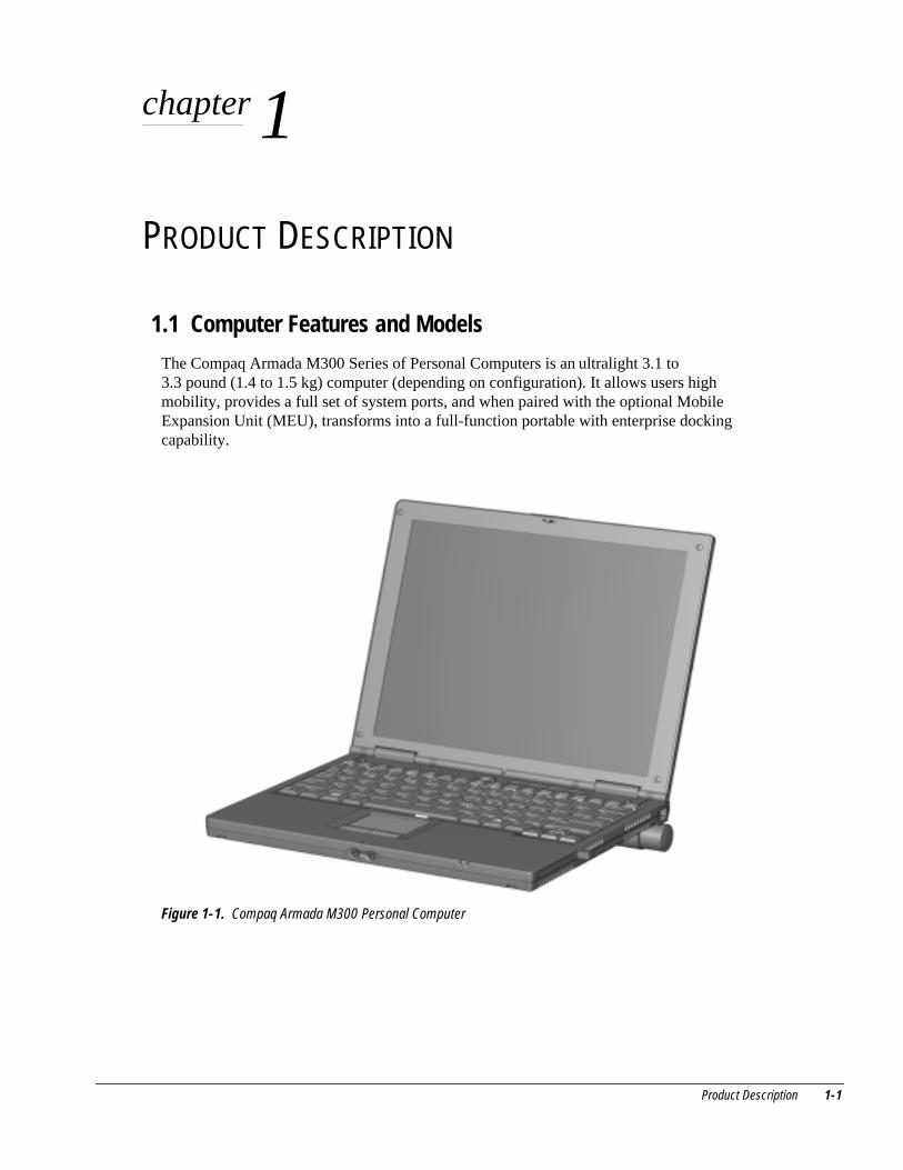
The Compaq Armada M300 Series of Personal Computers is an ultralight 3.1 to3.3 pound (1.4 to 1.5 kg) computer (depending on configuration). It allows users highmobility, provides a full set of system ports, and when paired with the optional MobileExpansion Unit (MEU), transforms into a full-function portable with enterprise dockingcapability.
Figure 1-1. Compaq Armada M300 Personal Computer
1-2 Product Description
Models
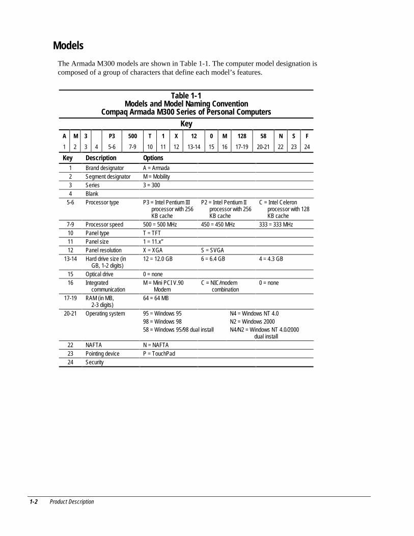
The Armada M300 models are shown in Table 1-1. The computer model designation iscomposed of a group of characters that define each model’s features.
Table 1-1Models and Model Naming Convention
Compaq Armada M300 Series of Personal ComputersKey
A M 3 P3 500 T 1 X 12 0 M 128 58 N S F
1 2 3 4 5-6 7-9 10 11 12 13-14 15 16 17-19 20-21 22 23 24
Key Description Options1 Brand designator A = Armada2 Segment designator M = Mobility3 Series 3 = 3004 Blank
5-6 Processor type P3 = Intel Pentium IIIprocessor with 256KB cache
P2 = Intel Pentium IIprocessor with 256KB cache
C = Intel Celeronprocessor with 128KB cache
7-9 Processor speed 500 = 500 MHz 450 = 450 MHz 333 = 333 MHz10 Panel type T = TFT11 Panel size 1 = 11.x”12 Panel resolution X = XGA S = SVGA
13-14 Hard drive size (inGB, 1-2 digits)
12 = 12.0 GB 6 = 6.4 GB 4 = 4.3 GB
15 Optical drive 0 = none16 Integrated
communicationM = Mini PCI V.90
ModemC = NIC/modem
combination0 = none
17-19 RAM (in MB,2-3 digits)
64 = 64 MB
20-21 Operating system 95 = Windows 9598 = Windows 9858 = Windows 95/98 dual install
N4 = Windows NT 4.0N2 = Windows 2000N4/N2 = Windows NT 4.0/2000
dual install22 NAFTA N = NAFTA23 Pointing device P = TouchPad24 Security
Product Description 1-3
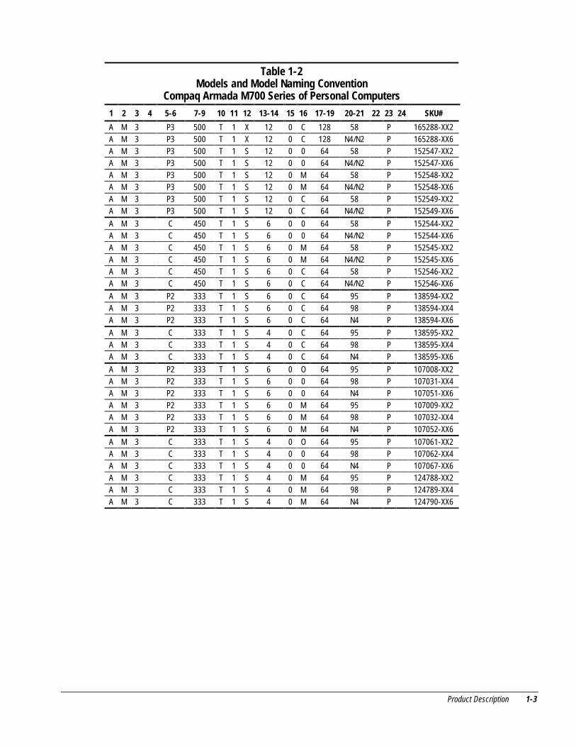
Table 1-2Models and Model Naming Convention
Compaq Armada M700 Series of Personal Computers1 2 3 4 5-6 7-9 10 11 12 13-14 15 16 17-19 20-21 22 23 24 SKU#
A M 3 P3 500 T 1 X 12 0 C 128 58 P 165288-XX2A M 3 P3 500 T 1 X 12 0 C 128 N4/N2 P 165288-XX6A M 3 P3 500 T 1 S 12 0 0 64 58 P 152547-XX2A M 3 P3 500 T 1 S 12 0 0 64 N4/N2 P 152547-XX6A M 3 P3 500 T 1 S 12 0 M 64 58 P 152548-XX2A M 3 P3 500 T 1 S 12 0 M 64 N4/N2 P 152548-XX6A M 3 P3 500 T 1 S 12 0 C 64 58 P 152549-XX2A M 3 P3 500 T 1 S 12 0 C 64 N4/N2 P 152549-XX6
A M 3 C 450 T 1 S 6 0 0 64 58 P 152544-XX2A M 3 C 450 T 1 S 6 0 0 64 N4/N2 P 152544-XX6A M 3 C 450 T 1 S 6 0 M 64 58 P 152545-XX2A M 3 C 450 T 1 S 6 0 M 64 N4/N2 P 152545-XX6A M 3 C 450 T 1 S 6 0 C 64 58 P 152546-XX2A M 3 C 450 T 1 S 6 0 C 64 N4/N2 P 152546-XX6
A M 3 P2 333 T 1 S 6 0 C 64 95 P 138594-XX2A M 3 P2 333 T 1 S 6 0 C 64 98 P 138594-XX4A M 3 P2 333 T 1 S 6 0 C 64 N4 P 138594-XX6
A M 3 C 333 T 1 S 4 0 C 64 95 P 138595-XX2A M 3 C 333 T 1 S 4 0 C 64 98 P 138595-XX4A M 3 C 333 T 1 S 4 0 C 64 N4 P 138595-XX6
A M 3 P2 333 T 1 S 6 0 O 64 95 P 107008-XX2A M 3 P2 333 T 1 S 6 0 0 64 98 P 107031-XX4A M 3 P2 333 T 1 S 6 0 0 64 N4 P 107051-XX6A M 3 P2 333 T 1 S 6 0 M 64 95 P 107009-XX2A M 3 P2 333 T 1 S 6 0 M 64 98 P 107032-XX4A M 3 P2 333 T 1 S 6 0 M 64 N4 P 107052-XX6
A M 3 C 333 T 1 S 4 0 O 64 95 P 107061-XX2A M 3 C 333 T 1 S 4 0 0 64 98 P 107062-XX4A M 3 C 333 T 1 S 4 0 0 64 N4 P 107067-XX6A M 3 C 333 T 1 S 4 0 M 64 95 P 124788-XX2A M 3 C 333 T 1 S 4 0 M 64 98 P 124789-XX4A M 3 C 333 T 1 S 4 0 M 64 N4 P 124790-XX6
1-4 Product Description
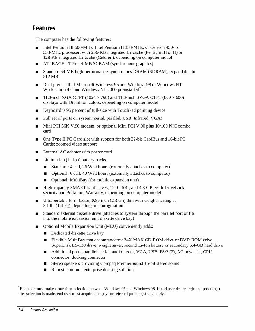
Features
The computer has the following features:
■ Intel Pentium III 500-MHz, Intel Pentium II 333-MHz, or Celeron 450- or333-MHz processor, with 256-KB integrated L2 cache (Pentium III or II) or128-KB integrated L2 cache (Celeron), depending on computer model
■ ATI RAGE LT Pro, 4-MB SGRAM (synchronous graphics)
■ Standard 64-MB high-performance synchronous DRAM (SDRAM), expandable to512 MB
■ Dual preinstall of Microsoft Windows 95 and Windows 98 or Windows NTWorkstation 4.0 and Windows NT 2000 preinstalled*
■ 11.3-inch XGA CTFT (1024 × 768) and 11.3-inch SVGA CTFT (800 × 600)displays with 16 million colors, depending on computer model
■ Keyboard is 95 percent of full-size with TouchPad pointing device
■ Full set of ports on system (serial, parallel, USB, Infrared, VGA)
■ Mini PCI 56K V.90 modem, or optional Mini PCI V.90 plus 10/100 NIC combocard
■ One Type II PC Card slot with support for both 32-bit CardBus and 16-bit PCCards; zoomed video support
■ External AC adapter with power cord
■ Lithium ion (Li-ion) battery packs
■ Standard: 4 cell, 26 Watt hours (externally attaches to computer)
■ Optional: 6 cell, 40 Watt hours (externally attaches to computer)
■ Optional: MultiBay (for mobile expansion unit)
■ High-capacity SMART hard drives, 12.0-, 6.4-, and 4.3-GB, with DriveLocksecurity and Prefailure Warranty, depending on computer model
■ Ultraportable form factor, 0.89 inch (2.3 cm) thin with weight starting at3.1 lb. (1.4 kg), depending on configuration
■ Standard external diskette drive (attaches to system through the parallel port or fitsinto the mobile expansion unit diskette drive bay)
■ Optional Mobile Expansion Unit (MEU) conveniently adds:
■ Dedicated diskette drive bay
■ Flexible MultiBay that accommodates: 24X MAX CD-ROM drive or DVD-ROM drive,SuperDisk LS-120 drive, weight saver, second Li-Ion battery or secondary 6.4-GB hard drive
■ Additional ports: parallel, serial, audio in/out, VGA, USB, PS/2 (2), AC power in, CPUconnector, docking connector
■ Stereo speakers providing Compaq PremierSound 16-bit stereo sound■ Robust, common enterprise docking solution
* End user must make a one-time selection between Windows 95 and Windows 98. If end user desires rejected product(s)after selection is made, end user must acquire and pay for rejected product(s) separately.
Product Description 1-5
Intelligent ManageabilityIntelligent Manageability consists of preinstalled software tools for the computer andCompaq servers that assist in tracking, troubleshooting, protecting, and maintaining thecomputer. It provides the following functions:
■ Asset Management: provides detailed configuration and diagnostic information.■ Fault Management: prevents, predicts, and alerts of impending hardware
problems.■ Security Management: protects unauthorized access to data and components.■ Configuration Management: optimizes the computer by providing the latest
drivers, utilities, and software, which are available on CD-ROM and the CompaqWeb site at www.compaq.com/support/portables.
NOTE: For further help with Intelligent Manageability, select Start � CompaqInformation Center � Intelligent Manageability
Accessing the Web AgentThe computer may have a preinstalled Web Agent that allows computer configurationinformation to be viewed using Web technology. To access this feature, select Start �Compaq Information Center � Insight Web Management.
If the computer does not have a preinstalled Web Agent, it can be downloaded from theCompaq Web site at www.compaq.com.
Asset ManagementAsset Management enables component information to be retrieved when on the road orconnected to the network.
Asset Management also enables the network administrator to remotely retrieveinformation from any Compaq computer connected to the network. The information canbe used to assist in tracking and maintaining the computer and its components. Itprovides the following information:
■ Inventory information—The network administrator can retrieve information aboutthe computer over the network by using Compaq Insight Manager or any PCmanagement tool provided by Compaq Solution Partners. Asset control informationretrieved from the computer includes:■ Manufacturer, model, and serial number of Compaq computers, monitors, hard
drives, battery packs, memory boards, processor speeds, and operating systems
■ Asset tag
■ System board and ROM revision levels
■ BIOS settings
■ Diagnostic information—Diagnostics for Windows includes information on harddrives, ports, video, sound, and other components. This application also allows theuser to run multi-threaded tests on hardware components. If problems are found,recommendations are provided.
All of the above information can be viewed, printed, or saved.

1-6 Product Description
Fault Management
Fault Management features minimize downtime and data loss by monitoring systemperformance and generating the following alerts:
■ Hard drive alert—provides 72-hour advance warning of impending hard driveproblems and can automatically start optional backup software.
■ System temperature alert—reports overheating. As the system temperature rises,this feature first adjusts fan speed and other cooling components, then displays analert, then shuts down the system.
■ Battery pack alert—reports charging problems and battery pack failure.■ Monitor alert—diagnoses and displays external monitor operational problems.■ Memory alert—reports memory board configuration changes when a memory
board is removed, added, or reconfigured. It also provides the previous and currentconfigurations for comparison.
The alerts work with or without network connection. If the computer is not connected tothe network, the network administrator cannot receive alerts from the computer.
Fault Management Alerts
Alerts can be enabled, disabled, and tested, and software can be set to back upinformation whenever a hard drive alert occurs.
■ While the computer is connected to a network, alerts pop up on the computerdisplay and are simultaneously reported to the network console.
■ System temperature alert—reports overheating. As the system temperature rises,this feature first adjusts fan speed and other cooling components, then displays analert, then shuts down the system.NOTE: A battery charging problem alert is reported only on the computer display.
■ When the computer is not connected to a network, the user will receive a local alert.
■ To set alerts, select the Intelligent Manageability icon in the system tray.
Security Management
Security Management features customize system security.
■ Power-On and Setup Passwords—prevent unauthorized access to information andcomputer configuration.
■ DriveLock—prevents unauthorized access to hard drives.■ Device disabling—prevents unauthorized data transfer through modems, serial
ports, parallel ports, and infrared ports on the computer and an optional dockingstation.
■ QuickLock/QuickBlank—locks the keyboard and clears the screen.■ Ownership Tag—displays ownership information during system restart.
Product Description 1-7
Configuration Management
Configuration Management optimizes software upgrade and customer supportprocedures. Compaq provides support software to optimize the performance of thecomputer. This support software is accessible through a monthly CD-ROMsubscription. Support software can also be downloaded from the Compaq Web site atwww.compaq.com/support/ portables.
Managing Power
The computer comes with a collection of power management features that allow batteryoperating time to be extended and power to be conserved. Use power management tomonitor most computer components such as the hard drive, processor, and display.
Accessing Power Management■ In Windows 95, select Start � Settings � Control Panel � Power to view or
adjust settings in Power Properties.■ In Windows NT 4.0, select Compaq Power instead of Power■ In Windows 98, select Power Management.
Power Management Levels
To extend the life of batteries, use the Battery Conservation tab in Power Properties.
■ If Windows 95 is running, select Start � Settings � Control Panel � Power toaccess Power Properties.
■ In Windows NT 4.0, select Compaq Power instead of Power.■ In Windows 98, select Power Management.
The level of battery conservation or the selection of preset power management levelscan be customized.
1-8 Product Description
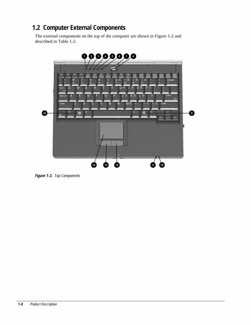
1.2 Computer External ComponentsThe external components on the top of the computer are shown in Figure 1-2 anddescribed in Table 1-2.
Figure 1-2. Top Components
Product Description 1-9
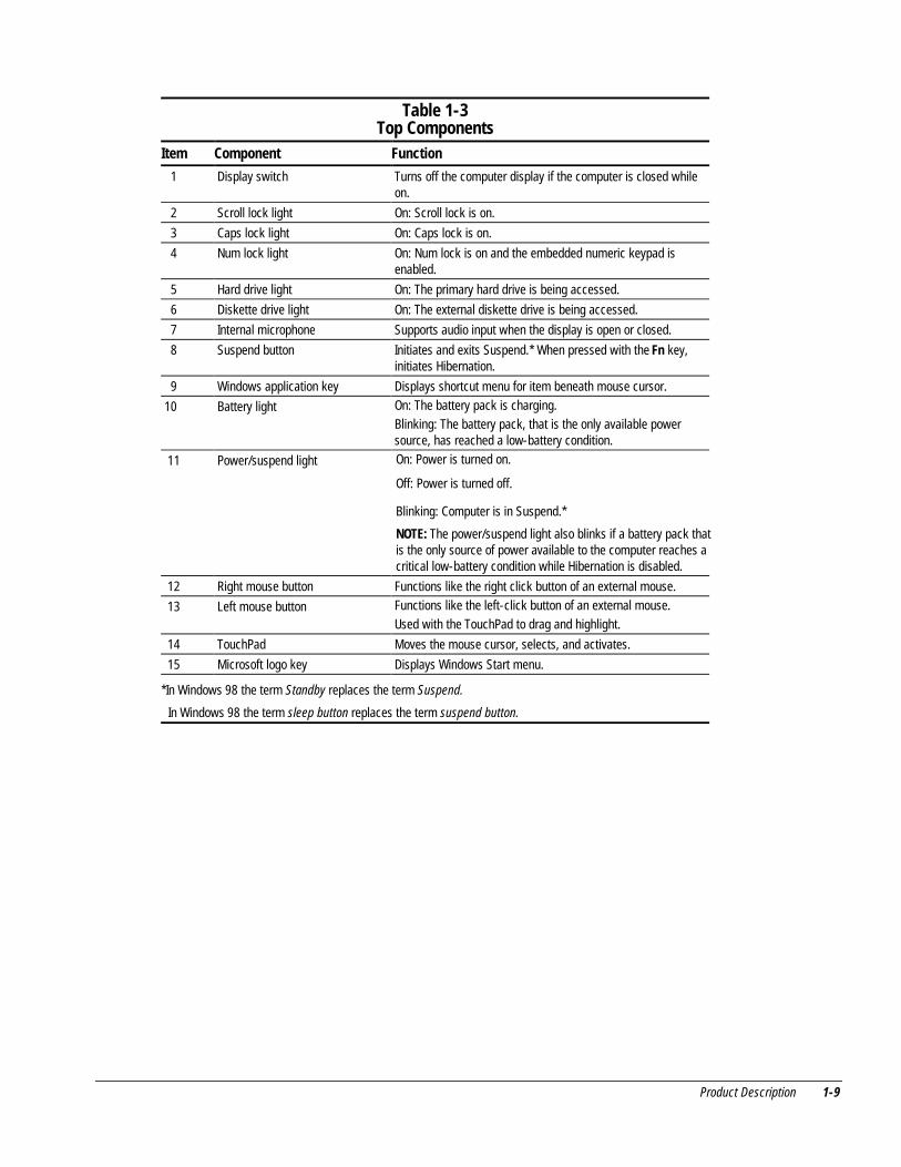
Table 1-3Top Components
Item Component Function
1 Display switch Turns off the computer display if the computer is closed whileon.
2 Scroll lock light On: Scroll lock is on.
3 Caps lock light On: Caps lock is on.
4 Num lock light On: Num lock is on and the embedded numeric keypad isenabled.
5 Hard drive light On: The primary hard drive is being accessed.
6 Diskette drive light On: The external diskette drive is being accessed.
7 Internal microphone Supports audio input when the display is open or closed.
8 Suspend button Initiates and exits Suspend.* When pressed with the Fn key,initiates Hibernation.
9 Windows application key Displays shortcut menu for item beneath mouse cursor.
10 Battery light On: The battery pack is charging.Blinking: The battery pack, that is the only available powersource, has reached a low-battery condition.
11 Power/suspend light On: Power is turned on.
Off: Power is turned off.
Blinking: Computer is in Suspend.*
NOTE: The power/suspend light also blinks if a battery pack thatis the only source of power available to the computer reaches acritical low-battery condition while Hibernation is disabled.
12 Right mouse button Functions like the right click button of an external mouse.
13 Left mouse button Functions like the left-click button of an external mouse.Used with the TouchPad to drag and highlight.
14 TouchPad Moves the mouse cursor, selects, and activates.
15 Microsoft logo key Displays Windows Start menu.
*In Windows 98 the term Standby replaces the term Suspend.
In Windows 98 the term sleep button replaces the term suspend button.
1-10 Product Description
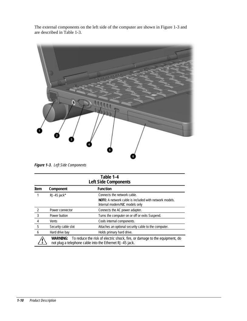
The external components on the left side of the computer are shown in Figure 1-3 andare described in Table 1-3.
Figure 1-3. Left Side Components
Table 1-4Left Side Components
Item Component Function
1 RJ-45 jack* Connects the network cable.NOTE: A network cable is included with network models.Internal modem/NIC models only
2 Power connector Connects the AC power adapter.
3 Power button Turns the computer on or off or exits Suspend.
4 Vents Cools internal components.
5 Security cable slot Attaches an optional security cable to the computer.
6 Hard drive bay Holds primary hard drive.
! WARNING: To reduce the risk of electric shock, fire, or damage to the equipment, donot plug a telephone cable into the Ethernet RJ-45 jack.
Product Description 1-11
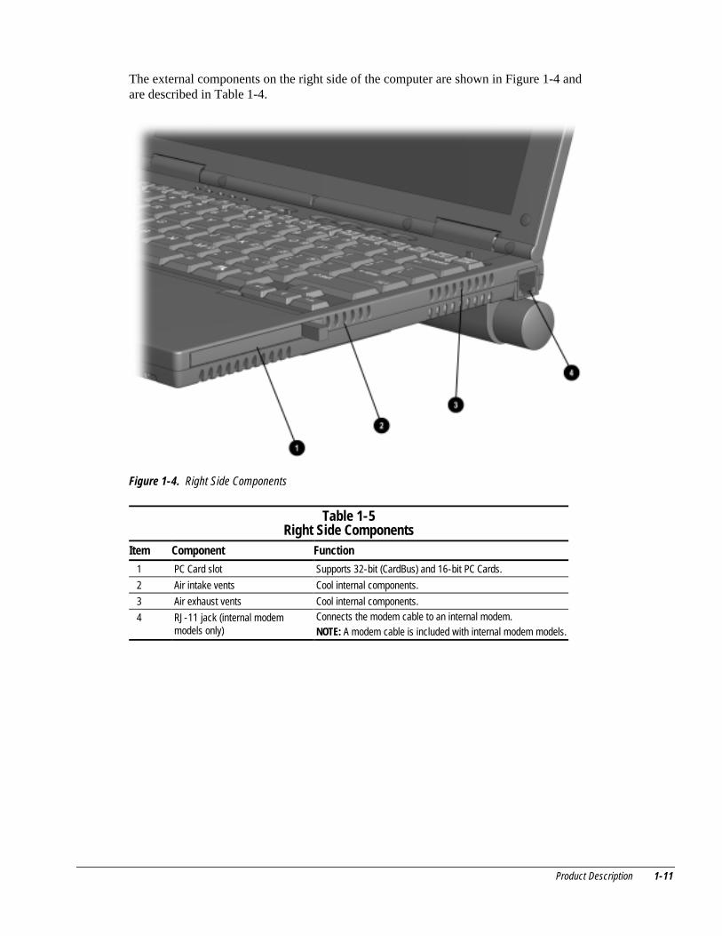
The external components on the right side of the computer are shown in Figure 1-4 andare described in Table 1-4.
Figure 1-4. Right Side Components
Table 1-5Right Side Components
Item Component Function
1 PC Card slot Supports 32-bit (CardBus) and 16-bit PC Cards.
2 Air intake vents Cool internal components.
3 Air exhaust vents Cool internal components.
4 RJ-11 jack (internal modemmodels only)
Connects the modem cable to an internal modem.NOTE: A modem cable is included with internal modem models.
1-12 Product Description
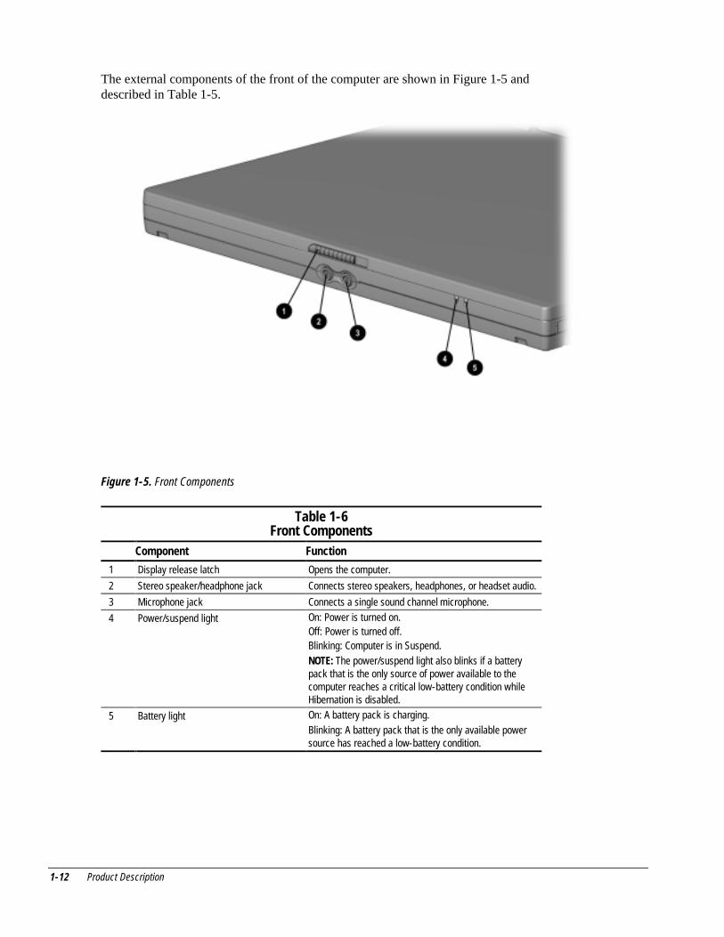
The external components of the front of the computer are shown in Figure 1-5 anddescribed in Table 1-5.
Figure 1-5. Front Components
Table 1-6Front Components
Component Function
1 Display release latch Opens the computer.
2 Stereo speaker/headphone jack Connects stereo speakers, headphones, or headset audio.
3 Microphone jack Connects a single sound channel microphone.
4 Power/suspend light On: Power is turned on.Off: Power is turned off.Blinking: Computer is in Suspend.NOTE: The power/suspend light also blinks if a batterypack that is the only source of power available to thecomputer reaches a critical low-battery condition whileHibernation is disabled.
5 Battery light On: A battery pack is charging.Blinking: A battery pack that is the only available powersource has reached a low-battery condition.
Product Description 1-13
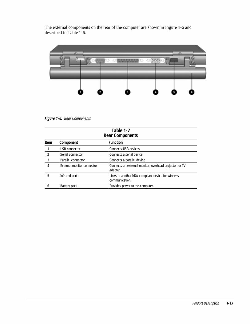
The external components on the rear of the computer are shown in Figure 1-6 anddescribed in Table 1-6.
Figure 1-6. Rear Components
Table 1-7Rear Components
Item Component Function
1 USB connector Connects USB devices
2 Serial connector Connects a serial device
3 Parallel connector Connects a parallel device
4 External monitor connector Connects an external monitor, overhead projector, or TVadapter.
5 Infrared port Links to another IrDA-compliant device for wirelesscommunication.
6 Battery pack Provides power to the computer.
1-14 Product Description
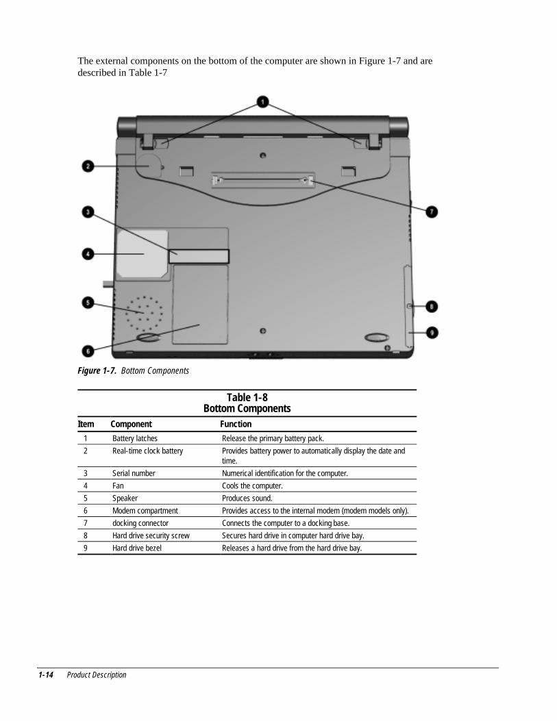
The external components on the bottom of the computer are shown in Figure 1-7 and aredescribed in Table 1-7
Figure 1-7. Bottom Components
Table 1-8Bottom Components
Item Component Function
1 Battery latches Release the primary battery pack.
2 Real-time clock battery Provides battery power to automatically display the date andtime.
3 Serial number Numerical identification for the computer.
4 Fan Cools the computer.
5 Speaker Produces sound.
6 Modem compartment Provides access to the internal modem (modem models only).
7 docking connector Connects the computer to a docking base.
8 Hard drive security screw Secures hard drive in computer hard drive bay.
9 Hard drive bezel Releases a hard drive from the hard drive bay.
Product Description 1-15
1.3 Design Overview
This section presents a design overview of key parts and features of the computer. Referto Chapter 3 for the illustrated parts catalog and Chapter 5 for removal and replacementprocedures.
System Board
The system board provides the following device connections:
■ Memory expansion board■ Hard drive■ Display■ Keyboard/Touchpad pointing device■ Audio■ Pentium II/Celeron processor■ Fan■ PC Cards■ Modem
The computer is equipped with an Intel Pentium III 500-MHz, Intel Pentium II333-MHz, or Celeron 450- or 333-MHz processor. For ventilation, an electrical fan isinstalled. The fan is controlled by a temperature sensor. The fan is designed to turn onautomatically when high temperature conditions exist. These conditions are affected byhigh external temperatures, system power consumption, power management/batteryconservation configurations, battery fast charging, and software applications. Exhaustair is displaced through the ventilation grill located on the right side of the computer.
CAUTION: To properly ventilate the computer, allow at least a 3-inch (7.6 cm) clearanceon the left and right sides of the computer.
������������ ���
chapter 2
�������������
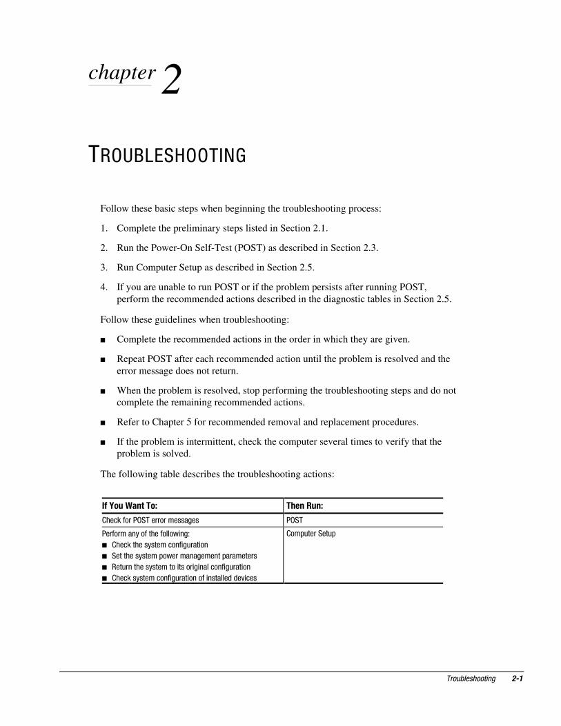
Follow these basic steps when beginning the troubleshooting process:
1. Complete the preliminary steps listed in Section 2.1.
2. Run the Power-On Self-Test (POST) as described in Section 2.3.
3. Run Computer Setup as described in Section 2.5.
4. If you are unable to run POST or if the problem persists after running POST,perform the recommended actions described in the diagnostic tables in Section 2.5.
Follow these guidelines when troubleshooting:
� Complete the recommended actions in the order in which they are given.
� Repeat POST after each recommended action until the problem is resolved and theerror message does not return.
� When the problem is resolved, stop performing the troubleshooting steps and do notcomplete the remaining recommended actions.
� Refer to Chapter 5 for recommended removal and replacement procedures.
� If the problem is intermittent, check the computer several times to verify that theproblem is solved.
The following table describes the troubleshooting actions:
������������� � �����
���������������������������� ����
������������������������� ��!
� �������������������� �"��� ��
� ���������������#����������������#���������
� ���"����������������� ����� � �������� �"��� ��
� ���������������� �"��� ������ �������$�$�% ���
��#"�������"#
��� ������������
��������������������
���������� Use AC power when running POST or Computer Setup. A low batterycondition could initiate Hibernation and interrupt the test.
Before running POST, complete the following steps:
1. Obtain established passwords. If you must clear the passwords, go to Section 2.2.
2. Ensure that the battery pack is installed and the power cord is connected to thecomputer and plugged into an AC power source.
3. Turn on the computer.
4. If a power-on password has been established, type the password and press ���
5. Run Computer Setup (Section 2.5). If a Setup password has been established, typethe password and press ���
6. Turn off the computer and all external devices.
7. Disconnect external devices that you do not want to test. If you want to use theprinter to log error messages, leave it connected to the computer.
��� � If a problem only occurs when an external device is connected to the computer,the problem could be with the external device or its cable. Isolate the problem byrunning POST with and without the external device connected.
8. Use Compaq Utilities and loopback plugs in the serial and parallel connectors if youplan to test these ports.
Follow these steps to run Compaq Utilities:
a. If you are running Compaq Utilities from the hard drive, turn on or restart thecomputer. Press !�" when the cursor appears in the upper-right corner of thescreen. If you do not press !�" in time, restart the computer and try again.
If you are running Compaq Utilities from diskette, insert the Compaq Utilitiesdiskette in drive A. Turn on or restart the computer.
b. Press �� to accept �#.
c. Select Prompted Diagnostics.
d. After “Identifying System Hardware” completes, select Interactive Testing andfollow the instructions on the screen.
������������ ���
�����$�����%�����&��'�
1. Turn off the computer.
2. Disconnect the computer (Section 5.4).
3. Remove the battery pack (Section 5.6).
4. Disconnect and remove the Real Time Clock (RTC) battery (Section 5.10).
5. Wait five minutes.
6. Reconnect the RTC battery.
7. Reconnect the AC Adapter. Do not reinstall the battery pack yet.
8. Turn on the computer.
��� ���Remember to set the date and time the next time the computer is turned on.
��(����&��)������)����*����+
The Power-On Self-Test (POST) is a series of tests that run every time the computer isturned on. POST verifies that the system is configured and functioning properly.
To run POST, complete the following steps:
1. Complete the preliminary steps (Section 2.1).
2. Turn on the computer.
If POST does not detect any errors, the computer beeps once or twice to indicate thatPOST has run successfully. The computer boots from the hard drive or from a bootablediskette if one is installed in the diskette drive.
��� ������������
��,������� ����������%��
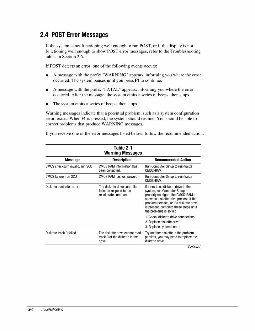
If the system is not functioning well enough to run POST, or if the display is notfunctioning well enough to show POST error messages, refer to the Troubleshootingtables in Section 2.6.
If POST detects an error, one of the following events occurs:
� A message with the prefix "WARNING" appears, informing you where the erroroccurred. The system pauses until you press !� to continue.
� A message with the prefix "FATAL" appears, informing you where the erroroccurred. After the message, the system emits a series of beeps, then stops.
� The system emits a series of beeps, then stops.
Warning messages indicate that a potential problem, such as a system configurationerror, exists. When !� is pressed, the system should resume. You should be able tocorrect problems that produce WARNING messages.
If you receive one of the error messages listed below, follow the recommended action.
��-����)�����%������%��
�����%� .��/����� ��/����'�'��/��
&���������"�� �%�� $'��"��� � &����(&� ������� ������)��������"#��$*
�"�� ��#"�������"#������ � � �� +� &��,�(&*
&����� �"��'��"��� � &����(&����������#����* �"�� ��#"�������"#������ � � �� +� &��,�(&*
- ����������������������� ����$ �������$� %�������������� ��$�������#��$������������ )�����������$*
�������� �����$ �������$� %�� �����������'��"�� ��#"�������"#���#��#��������� �"������� &��,�(&�����������$ �������$� %��#������*������#��)����#��� ���'���� ����$ �������$� %� ��#������'����#��������������#��"�� �����#��)����� �����%�$!
.*� �����$ �������$� %��������� ���*
/*���#�����$ �������$� %�*
0*���#������������)���$*
- �������������1��� ��$ ����$ �������$� %������������$������1��������$ ������� �����$� %�*
������������$ ������*�������#��)���#��� ���'���"��������$������#��������$ �������$� %�*
Continued
������������ ���
��-����)���Continued
�����%� .��/����� ��/����'�'��/��
��$�$ ������������������� �������$�$� %��������������� ��$������#��$�������������������$*
���������$� %��#���������*��"�������������������$�����������������$������� ���*
2��)���$�������������� �"�� �������)���$��� ��$���������,�����������$*
��#����������������)���$*
2��)���$��� �"�� �������)���$��� ��$�������#��$�������������-�������$*
��#������������)���$*�������#��)���#��� ���'���#����������������)���$*
��� �����"#��������� ����1 ����#�� �$ ��� ���� �����"#�� ��������"�� ��*
��#����������������)���$*
��&����3333�4����������5�� �����+����������"��4++5
(�� ��������$�#������&����������$���������#�� � �$�$$����*
����������3��������$�#����4�"�������% $������$5����$����� ��� �� �� ���"� ������������ ��*
� ��6-��������"#��,��"��� � ����� �����$�$���������$� ����������� �����������%��)�������"#��$'�#��� )���)����#��������*
.*��"�� ��#"�������"#*
/*���#��)�����#��� ���'���#�����������)���$*
��$�$ ���33��� �"���4��������5 (��� �"������������������"���$�������� ��������������������$$� %�*
.*��"������- ��*
/*� �����$ ��� ��-�����$7 �$����89*
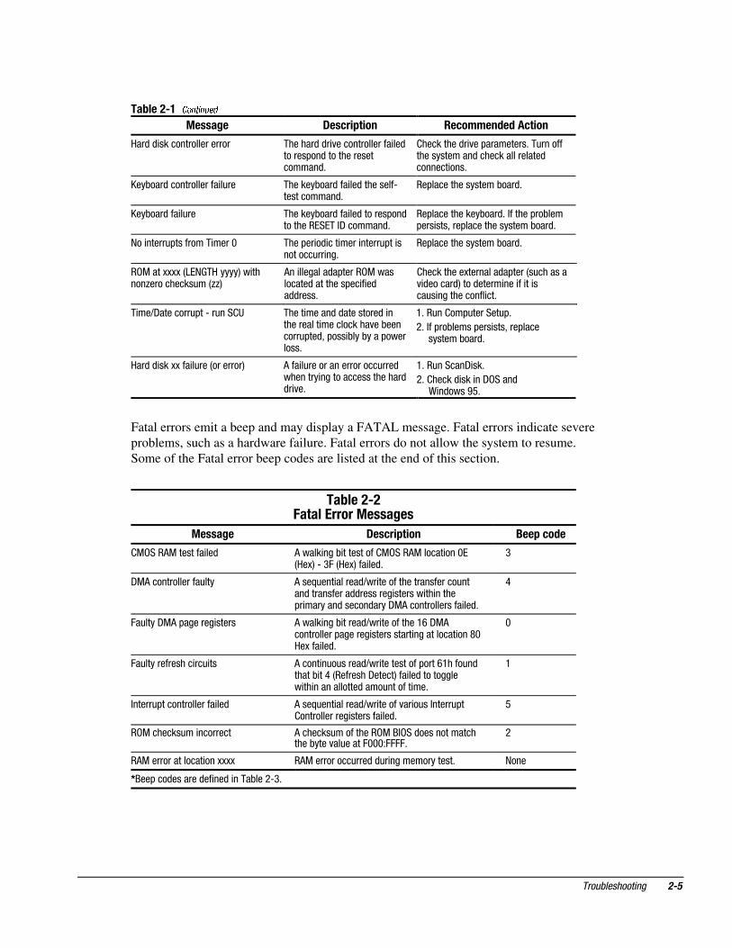
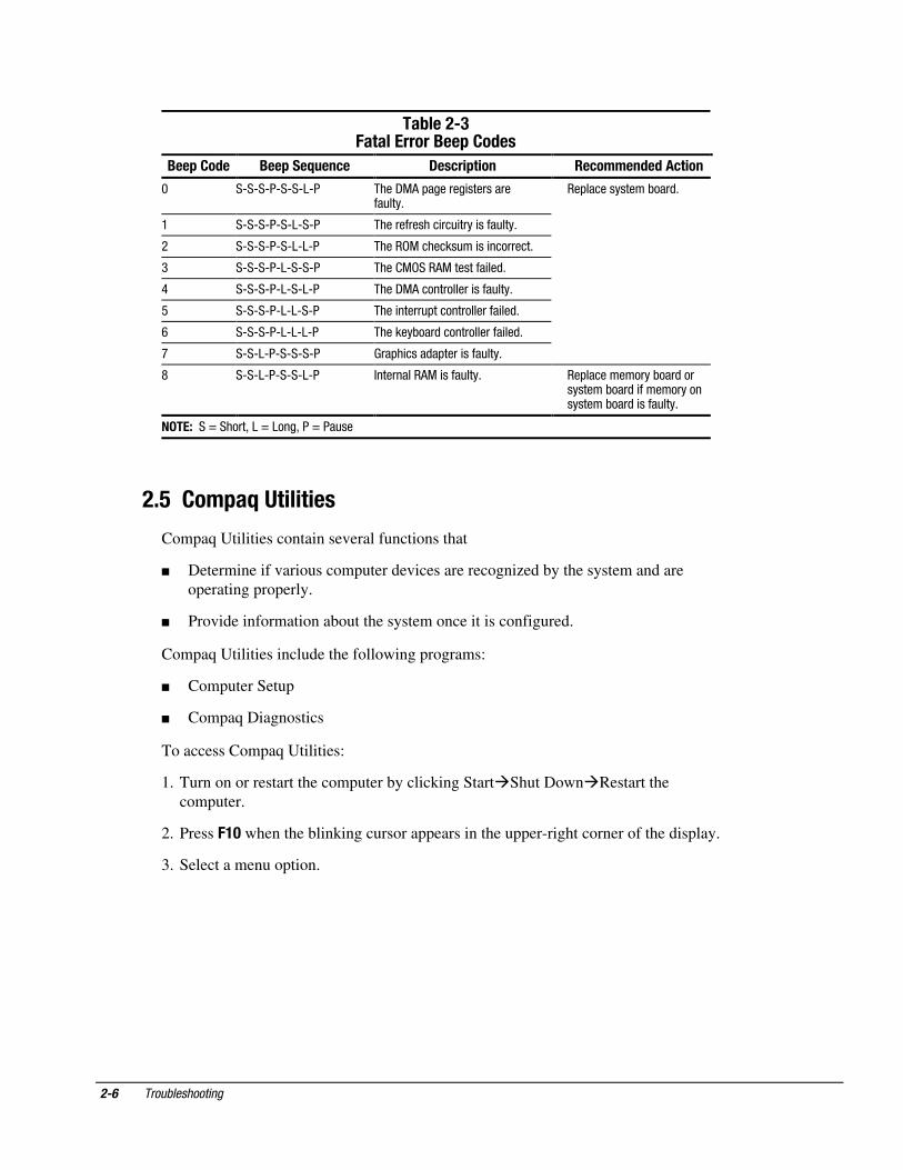
Fatal errors emit a beep and may display a FATAL message. Fatal errors indicate severeproblems, such as a hardware failure. Fatal errors do not allow the system to resume.Some of the Fatal error beep codes are listed at the end of this section.
��-����)�!���� ����������%��
�����%� .��/����� 0����/�'�
&����(&�������� ��$ (����� ���) ���������� &����(&������ ���1�4�35�,�0:�4�35��� ��$*
0
-&(��������������"��� (���;"��� ������$6�� ���������������������"����$�����������$$�������� ������� �� �����#� �������$������$����-&(��������������� ��$*
<
:�"����-&(�#������� ����� (����� ���) �����$6�� ����������.=�-&(�����������#������� ����������� ����������� ���>1�3��� ��$*
1
:�"������������� ��" �� (����� �"�"�����$6�� �����������#����=.����"�$�����) ��<�4��������-�����5��� ��$����������� �� ������������$����"������� ��*
.
�����"#��������������� ��$ (���;"��� ������$6�� ������%�� �"�������"#� ������������� �������� ��$*
9
��&�������"�� �������� (�������"�����������&�����$�����������������)����%��"�����:111!::::*
/
�(&��������������� ���3333 �(&����������"���$�$"� ��������������* ����
1���#���$�������$�� ��$� ����)���/,0*
��� ������������
��-����)(!���� �����0����$�'��
0����$�'� 0������2��/� .��/����� ��/����'�'��/��
1 �,�,�,�,�,�,�,� ����-&(�#������� �����������"���*
��#������������)���$*
. �,�,�,�,�,�,�,� ������������� ��" ���� ����"���*
/ �,�,�,�,�,�,�,� ������&�������"�� �� ��������*
0 �,�,�,�,�,�,�,� ���� &����(&�������� ��$*
< �,�,�,�,�,�,�,� ����-&(������������ ����"���*
9 �,�,�,�,�,�,�,� ���� �����"#��������������� ��$*
= �,�,�,�,�,�,�,� �������)���$�������������� ��$*
? �,�,�,�,�,�,�,� ���#� ����$�#���� ����"���*
> �,�,�,�,�,�,�,� ���������(&� ����"���* ��#������������)���$����������)���$� ������������������)���$� ����"���*
��� �����@������'���@�����'���@���"��
��3��$����2�4������
Compaq Utilities contain several functions that
� Determine if various computer devices are recognized by the system and areoperating properly.
� Provide information about the system once it is configured.
Compaq Utilities include the following programs:
� Computer Setup
� Compaq Diagnostics
To access Compaq Utilities:
1. Turn on or restart the computer by clicking Start�Shut Down�Restart thecomputer.
2. Press !�" when the blinking cursor appears in the upper-right corner of the display.
3. Select a menu option.
������������ ���
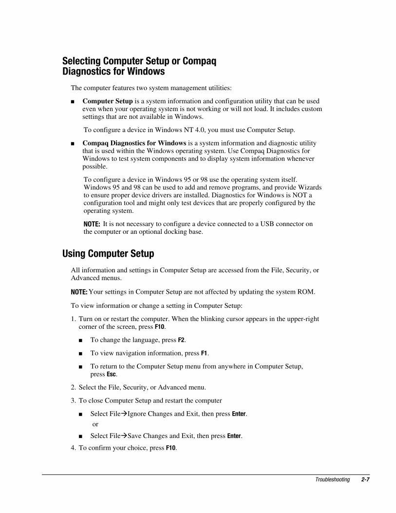
����/�%�$���������������$����2.��%���/��������'�&�
The computer features two system management utilities:
� Computer Setup is a system information and configuration utility that can be usedeven when your operating system is not working or will not load. It includes customsettings that are not available in Windows.
To configure a device in Windows NT 4.0, you must use Computer Setup.
� Compaq Diagnostics for Windows is a system information and diagnostic utilitythat is used within the Windows operating system. Use Compaq Diagnostics forWindows to test system components and to display system information wheneverpossible.
To configure a device in Windows 95 or 98 use the operating system itself.Windows 95 and 98 can be used to add and remove programs, and provide Wizardsto ensure proper device drivers are installed. Diagnostics for Windows is NOT aconfiguration tool and might only test devices that are properly configured by theoperating system.
��� � It is not necessary to configure a device connected to a USB connector onthe computer or an optional docking base.
4��%�$�����������
All information and settings in Computer Setup are accessed from the File, Security, orAdvanced menus.
��� � Your settings in Computer Setup are not affected by updating the system ROM.
To view information or change a setting in Computer Setup:
1. Turn on or restart the computer. When the blinking cursor appears in the upper-rightcorner of the screen, press !�".
� To change the language, press !�.
� To view navigation information, press !�.
� To return to the Computer Setup menu from anywhere in Computer Setup,press �/.
2. Select the File, Security, or Advanced menu.
3. To close Computer Setup and restart the computer
� Select File�Ignore Changes and Exit, then press ��.
or
� Select File�Save Changes and Exit, then press ��.
4. To confirm your choice, press !�".
�� ������������
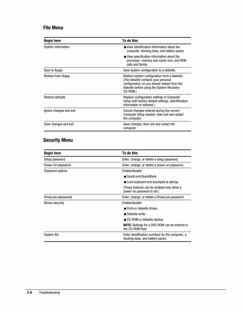
!�������
0�%�� ��� ���'�� ��
������� ������� �� � A ��� $��� � ��� ��� ������� ����)�"��������#"���'�$��� ���)���'���$�)�������#����*
� A ����#�� � ��� ��� ������� ����)�"�����#��������'����������$�������� +�'���$���&$������$���� ��*
��%��������##� ��%������������� �"��� ��������$ ������*
����������������##� ������������������� �"��� ����������$ ������*4����$ ������������ �����"��#����������� �"��� ��'������"����"�$�����������������$ �������)������"� ������������������%��� -,��&*5
��������$���"��� ��#��������� �"��� ������� ���� �� ��#"������"#�� �����������$���"������� ���*�4$��� � ��� �� ������� ��� ������ ��$*5
����������������$��3 � ��������������������$�$"� ��������"����� ��#"�������"#����� ��'�������3 ����$���������������#"���*
��%������������$��3 � ��%���������'�������3 ����$���������������#"���*
��/��������
0�%�� ��� ���'�� ��
���"#�#������$ �����'�������'����$�����������"#�#������$*
�����,���#������$ �����'�������'����$��������#����,���#������$*
�������$��#� ��� ���)��6$ ��)��!
� B" ������6B" �������
� ��������)���$���$���"��#�$���������"#*
4����������"��������)�����)��$������������#����,���#������$� �����*5
-� %������#������$� �����'�������'����$��������-� %������#������$*
-�% ������"� �� ���)��6$ ��)��
� ���������$ �������$� %��*
� - ��������� ��*
� -,��&����$ ������������"#*
��� ������ ����������-A-,��&�����)��������$� ����� -,��&�� ��$*
�������-� ������ $��� � ��� ����"�)���������������#"���'��$��� ���)���'���$�)�������#����*
������������ ��
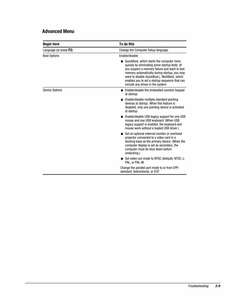
�'5�/�'����
0�%�� ��� ���'�� ��
����"����4���#�����!�5 ���������� ��#"�������"#�����"���*
������#� ��� ���)��6$ ��)��
� B" ������'��� �����������������#"��������;" �����)���� � ��� �������������"#������*�4���"��"�#��������������� �"�����$���������������������"����� ������$"� ��������"#'���"������������$ ��)���B" ������*5��&"�� ����'��� �����)������"���������������"#���;"������������� ���"$������$� %��� ������������*
-�% ����#� ��� � ���)��6$ ��)���������)�$$�$��"��� �����#�$��������"#*
� ���)��6$ ��)����"�� #�������$��$�#� �� ��$�% ������������"#*�7������ ������"��� �$ ��)��$'����������#� �� ���$�% ��� ����� %���$��������"#*
� ���)��6$ ��)���������������"##�����������������"�����$������������)���$*�47���������������"##���� �����)��$'��������)���$���$��"��������� ���"�������$�$�����$� %��*5
� ��������#� ������3���������� ��������%�����$#��C��������������$������% $������$� ���$��� ���)�����������#� �����$�% ��*�47����������#"����$ �#���� ��������������$���'�������#"�����"���)����"��$����)�����"�$��� ��*5
� ����% $��,�"����$�������� �4$���"��5'���� ,D'�(�'�����(�,&*
����������#��������#������$����������������'����$��$'�) $ ���� ����'����� �*
���� ������������
4��%�$����2�.��%���/��������'�&�
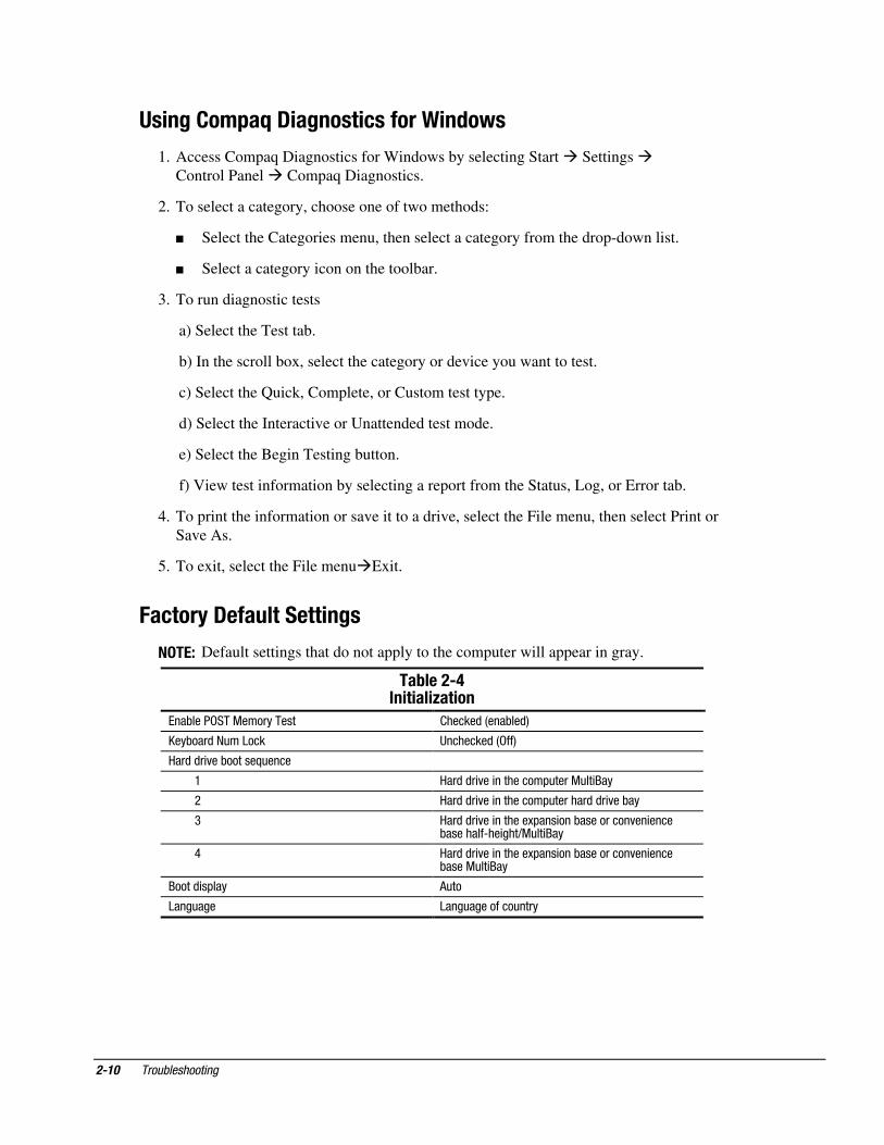
1. Access Compaq Diagnostics for Windows by selecting Start � Settings �Control Panel � Compaq Diagnostics.
2. To select a category, choose one of two methods:
� Select the Categories menu, then select a category from the drop-down list.
� Select a category icon on the toolbar.
3. To run diagnostic tests
a) Select the Test tab.
b) In the scroll box, select the category or device you want to test.
c) Select the Quick, Complete, or Custom test type.
d) Select the Interactive or Unattended test mode.
e) Select the Begin Testing button.
f) View test information by selecting a report from the Status, Log, or Error tab.
4. To print the information or save it to a drive, select the File menu, then select Print orSave As.
5. To exit, select the File menu�Exit.
!�/����.���������%�
��� � Default settings that do not apply to the computer will appear in gray.
��-����),������6���
���)��������&���������� �����$�4���)��$5
2��)���$��"������ ��������$�4���5
��$�$� %��)������;"����
. ��$�$� %�� ���������#"����&"�� ���
/ ��$�$� %�� ���������#"�������$�$� %��)��
0 ��$�$� %�� �������3#��� ���)����������%�� ����)��������,�� ���6&"�� ���
< ��$�$� %�� �������3#��� ���)����������%�� ����)����&"�� ���
�����$ �#��� ("��
����"��� ����"���������"����
������������ ����
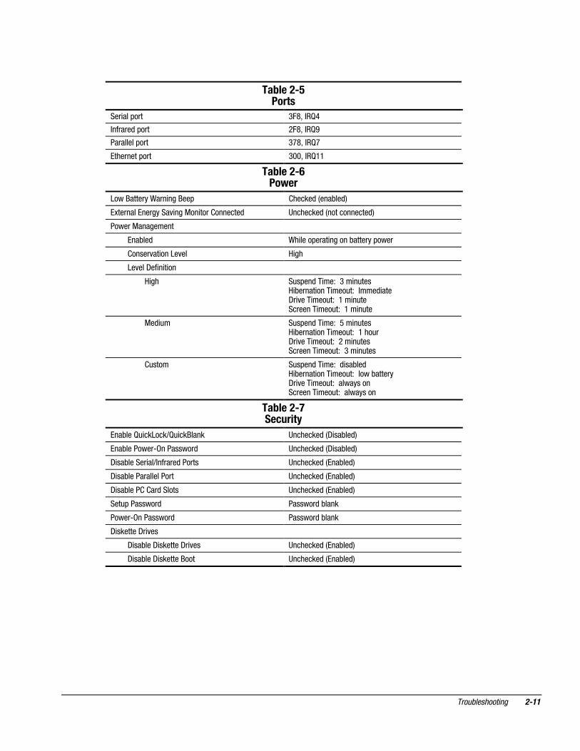
��-����)3����
��� ���#��� 0:>'��B<
������$�#��� /:>'��B8
���������#��� 0?>'��B?
���������#��� 011'��B..
��-����)7��&��
������������7��� ������# �����$�4���)��$5
�3����������������% ���&�� ���� �������$ ��������$�4������������$5
������&���������
���)��$ 7� ����#���� ������)�������#����
�����%�� �����%�� ��
��%���-�� � � ��
�� �"�#��$�� ��!��0�� �"��� )����� ���� ���"�!�����$ ���-� %��� ���"�!��.�� �"���������� ���"�!��.�� �"��
&�$ "� �"�#��$�� ��!��9�� �"��� )����� ���� ���"�!��.���"�-� %��� ���"�!��/�� �"����������� ���"�!��0�� �"���
"���� �"�#��$�� ��!��$ ��)��$ )����� ���� ���"�!������)������-� %��� ���"�!������������������� ���"�!�����������
��-����)8��/����
���)���B" ������6B" ������� ��������$�4- ��)��$5
���)��������,����������$ ��������$�4- ��)��$5
- ��)������ ��6������$������ ��������$�4���)��$5
- ��)���������������� ��������$�4���)��$5
- ��)���� � ��$������ ��������$�4���)��$5
���"#��������$ �������$�)����
�����,����������$ �������$�)����
- �������-� %��
- ��)���- �������-� %�� ��������$�4���)��$5
- ��)���- ����������� ��������$�4���)��$5
���� ������������
��7������-��� ���%��� ���.��%���/�
This section provides information about how to identify and correct some commonhardware, memory, and software problems. It also explains several types of messagesthat may be displayed on the screen.
Since symptoms can appear to be similar, carefully match the symptoms of thecomputer malfunction against the problem description in the Troubleshooting tables toavoid a misdiagnosis.
0�����������/�%�����
When troubleshooting a problem, check the following items for possible solutionsbefore replacing parts:
� Verify that cables are connected properly to the suspected defective parts.
� Verify that all required device drivers are installed.
� Verify that all printer drivers have been installed for each application.
�-���%�4�'�����������&� ����������%��
Compaq Info Messenger allows you to set a customized search of the Compaq Website. By registering for this utility, you can stay up to date with software and hardwareinformation specific to your system.
� To access Compaq Info Messenger, go to www.compaq.com and select InfoMessenger.
� To register, follow the instructions on the Info Messenger page. When yourregistration is complete, you can
� Implement your customized search whenever you prefer from the InfoMessenger page.
� Set Info Messenger to send you the information by email as it becomes available.
Info Messenger will also inform you if there are updates to the system ROM for yourcomputer.
������������ ����
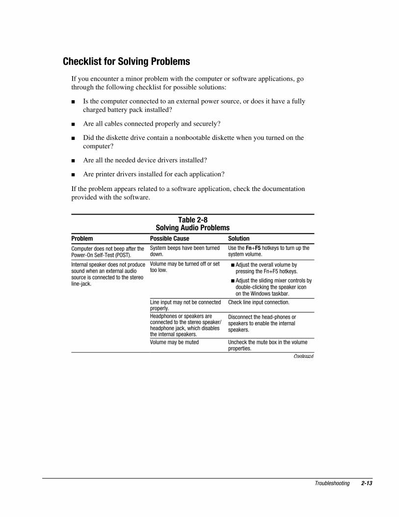
$ �/9�����������5�%����-����
If you encounter a minor problem with the computer or software applications, gothrough the following checklist for possible solutions:
� Is the computer connected to an external power source, or does it have a fullycharged battery pack installed?
� Are all cables connected properly and securely?
� Did the diskette drive contain a nonbootable diskette when you turned on thecomputer?
� Are all the needed device drivers installed?
� Are printer drivers installed for each application?
If the problem appears related to a software application, check the documentationprovided with the software.
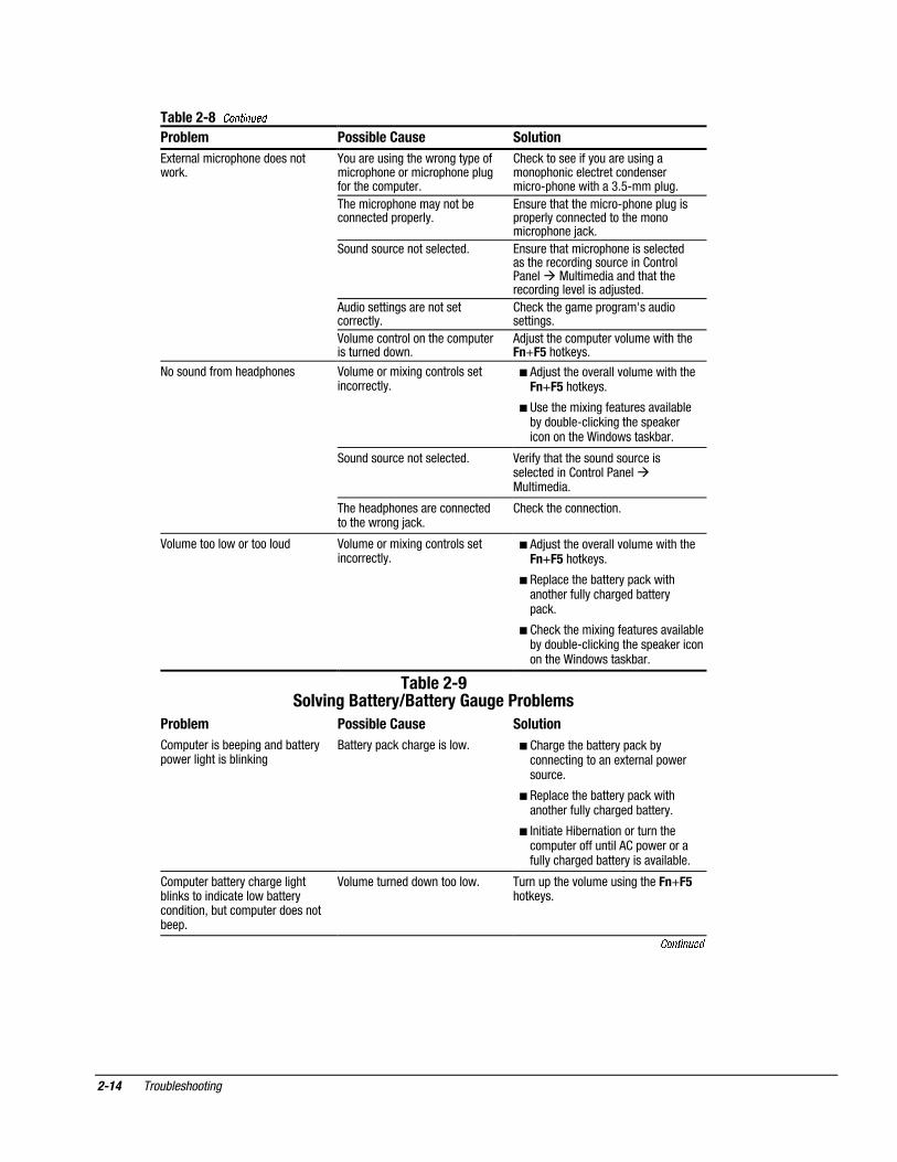
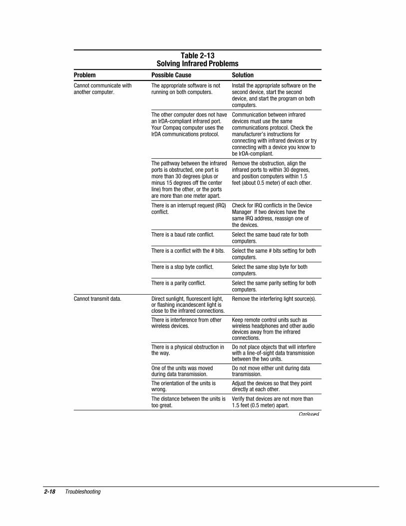
��-����):���5�%���'������-����
���-��� �����-���$���� ������
��#"����$��������)��#���������������,�������,�����4����5*
�������)��#����%��)�����"���$$���*
��������!E!3�������������"���"#�����������%��"��*
���������#������$��������#��$"����"�$����������3��������"$ ���"���� ����������$��������������� ��,C���*
A��"�������)���"���$������������������*
� ($C"��������%������%��"���)�#���� �������:�E:9��������*
� ($C"��������� $ ���� 3������������)�$�")��,�� �� ��������#������ ����������7 �$��������)��*
� �� ��� �#"����������)����������$#��#����*
� ������ ��� �#"��������� ��*
� ���$#����������#������������������$����������������#�����6���$#�����C���'��� ���$ ��)������� ���������#������*
�- ����������������$,#���������#�������������)������� ��������#������*
� �A��"�������)���"��$ ��������������"���)�3� ������%��"��#��#��� ��*
Continued
���� ������������
���-����):��Continued
����-��� ������-���$���� �������
��3�������� ���#�����$�����������*
�F�"�����"� ���������������#����� ���#��������� ���#�����#�"������������#"���*
� ������������ ����"�����"� ��������#��� ��������������$������ ���,#������ �����0*9,���#�"�*
� ������ ���#�������������)���������$�#��#����*
����"������������� ���,#�����#�"�� �#��#�������������$������������� ���#�����C���*
� ���"�$���"���������������$* ����"��������� ���#����� ���������$������������$ �����"���� �� ��������������&"�� ��$ ����$��������������$ �����%��� ���$C"���$*
� �("$ ������ ������������������������*
� ��������������#������G���"$ ����� ���*
� �A��"���������������������#"��� ���"���$�$���*
�($C"����������#"����%��"���� ������!E!3��������*
������"�$���������$#����� �A��"������� 3 ��������������� ����������*
� ($C"��������%������%��"���� ������!E!3��������*
� ��������� 3 �������"�����%� ��)��)��$�")��,�� �� ��������#����� �����������7 �$��������)��*
� ���"�$���"���������������$* �A�� ��������������"�$���"���� ��������$� �� ��������������&"�� ��$ �*
� ��������$#������������������$�������������C���*
� ���������������� ��*
�A��"��������������������"$ �A��"������� 3 ��������������� ����������*
� ($C"��������%������%��"���� ������!E!3��������*
� ��#���������)�������#����� �����������"����������$�)������#���*
� ���������� 3 �������"�����%� ��)��)��$�")��,�� �� ��������#������ ����������7 �$��������)��*
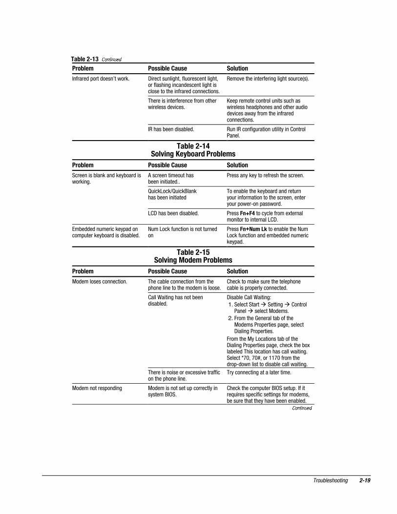
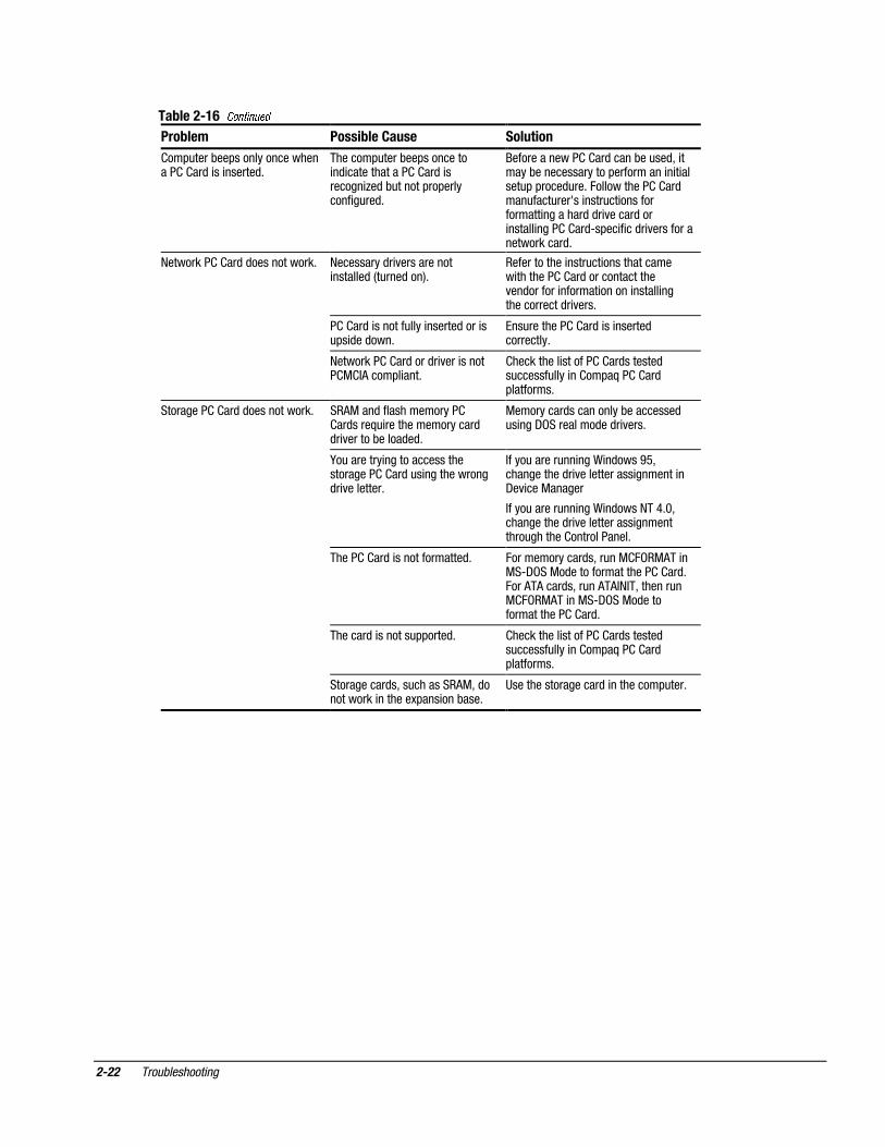
��-����);���5�%�0����<0�����=��%�����-����
���-��� ������-���$���� ������
� ��#"���� ��)��# �����$�)������#������ ���� ��)� �� ��
���������#����������� �����* � ����������)�������#����)�������� ����������3�������#������"���*
� ��#���������)�������#����� �����������"����������$�)������*
� � � ���� )����� �������"���������#"��������"�� ��( �#����������"����������$�)������� ���%� ��)��*
� ��#"����)��������������� ���)� ������� �$ ���������)���������$ � ��'�)"�����#"����$�������)��#*
�A��"����"���$�$�����������* ��"���"#�����%��"���"� �������!E!3�������*
Continued
������������ ����
���-����);��Continued
����-��� ������-���$���� �������
���������#����� �������������* ���������#���������3#���$������#����"����3������*
�(������ �����������)�������#���������"��������������#����"��*
� ���������#���� �������$��������$* ������� �����;" ��$*
� ���������#���������3���$�$� ��"���"��� ��������*
�������$ ��������)�������#���*
� ��#"������"��$������$����������������������#��� �������)�������#���*
� )����� ����������� � � ���$)����������% �������)�������#���*
�7���� ������*
����������������$�������������%�������*
��������� ���3#���$����� �������#����"���*
��"���������#"���� �����������#������$��������������)�������#���*
� ��������� ���3#���$�����3����������$����#����"���*
��"���������#"���� �����������#������$��������������)�������#���*
���� ��������������$�$��#���� �����#����"�����������������)������� ������.1� ����<1� 491�:����.1<�:5*�������������$�$�����������#����"����������������)������� �������1� ����01� �40/�:���>=�:5*
� ���������������%�� ��� ��$ ��)��$����������$�� �*
�����������)�������������%�� �����%��*
� �(���3�������$�% ��� ��$�� � ������)������*
��"��������������%�������3������$�% ������� � ��$����������� ��"��*
� �����������"�������)� ����"�������$���;" ������� )��� ��*
������ )�����������"��*
�-������$�� ����"���)�������%���� ������#"���� ���"���$���*
����������� ��� �����)����������������$�������$���� ���"���"��� ��*
� ��������#����'�������"������������#"����� �������#������� ���
� ��#��������������� ��� ����)������*
�����������"��������� ����"����* �����)�������#�����������$��� )��� ��*
������ )���������)������*
� �����)�������#��������������$������$���� ���"���"��� ��*
���#���������)�������#���*
���������#���� ����������������� ��*
�7��� ������"���$"� �������� ��* ������� �����;" ��$*
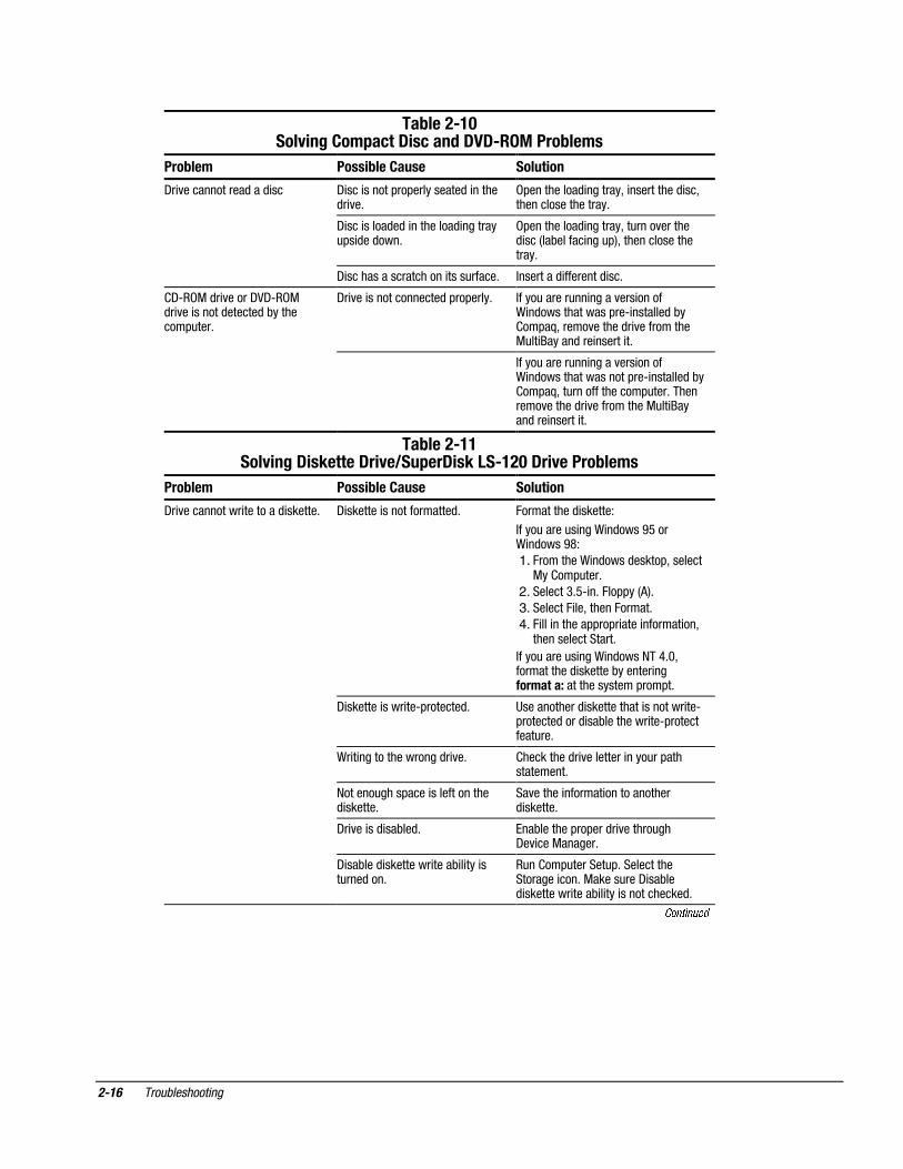
���� ������������
���-����)�"���5�%�$����/�.��/��'�.>.)�������-����
����-��� ������-���$���� �������
�-� %������������$���$ �� �- ��� ������#��#����������$� �����$� %�*
��#����������$ �������'� ����������$ ��'�������������������*
� �- ��� �����$�$� ���������$ �������"#� $��$���*
��#����������$ �������'��"����%������$ ���4��)������ ���"#5'�������������������*
� �- �������������������� ����"�����* ���������$ ��������$ ��*
� -,��&�$� %�����-A-,��&$� %�� ������$������$�)��������#"���*
�-� %�� ��������������$�#��#����* �����"������"�� �����%��� �����7 �$�������������#��, �������$�)� ��#�;'�����%������$� %����������&"�� ������$��� ������ �*
� � �����"������"�� �����%��� �����7 �$�����������������#��, �������$�)� ��#�;'��"��������������#"���*���������%������$� %�����������&"�� �����$��� ������ �*
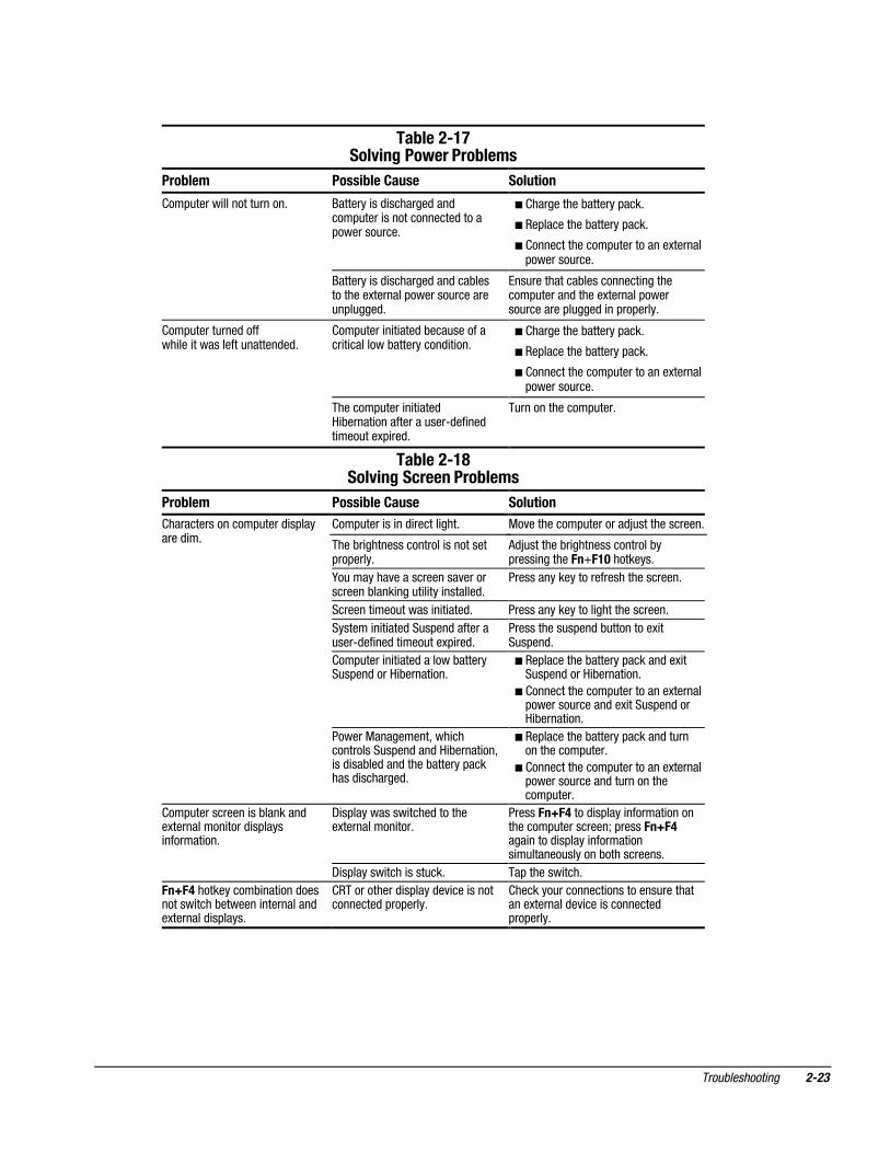
��-����)�����5�%�.��9���.��5�<�����.��9�?�)��"�.��5�����-����
���-��� �����-���$���� ������
-� %����������� ��������$ ������* - ������� ��������������$* :����������$ ������!
����"�����"� ���7 �$����89���7 �$����8>!
1. :��������7 �$����$�����#'�������&�� ��#"���*
2. �������0*9, �*�:��##��4(5*
3. �������: ��'������:�����*
4. : ��� �������##��#� ���� ������� ��'�����������������*
����"�����"� ���7 �$�������<*1'�����������$ �������)������� �������������������������#���#�*
- ������� ���� ��,#�������$* ������������$ ������������ �������� ��,#�������$����$ ��)��������� ��,#����������"��*
7� � ����������������$� %�* ���������$� %��������� ����"��#������������*
�������"����#���� �������������$ ������*
��%������ ������� �������������$ ������*
-� %�� ��$ ��)��$* ���)�������#��#���$� %������"��-�% ���&������*
- ��)���$ ��������� ����) � ��� ��"���$���*
�"�� ��#"�������"#*������������������� ���*�&�����"���- ��)��$ ��������� ����) � ��� ������������$*
Continued
������������ ����
���-����)����Continued
����-��� ������-���$���� �������
��������������������"#�����$ �����������"#��- �����,./1$� %�*
(�)����)���$ ������� ������ �����$� %�*
A�� ����������$ �������� ������������������������ ���� �� ������$� %�*
- �������)����) � ��� ��$ ��)��$� � ��#"�������"#*
���)���$ �������)����) � ��� � ��#"�������"#'����"� ������"*
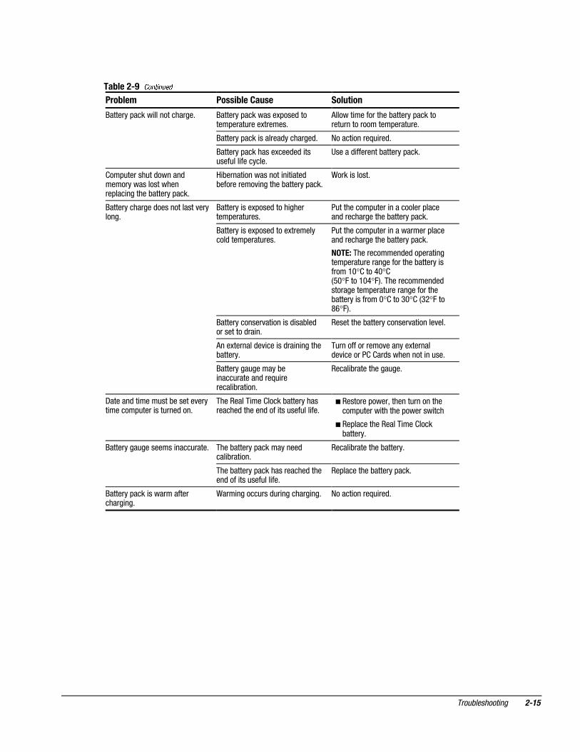
��-����)�����5�%�@��'�.��5�����-����
���-��� �����-���$���� ������
(����� ��� ������� �� ���������$�$� %�� ���"��������������"�"��*
��$�$� %��������$�����#����������$"������ ���"����$� ������3 � �������� �*
7� �������������������������������#��% �"������%�$�$������� ���������#� ����� � � �� ���������#����������*
��$�$� %�� �����������$6����#� � +�$��������������*
�"������- �����$�- ���-�����������*
��$�$� %��$������������* ��$�$� %�� �����������$�#��#����* �"���������$�"�#�"���������#"���'����%���������$�$� %�'���$��� ������������$�$� %�*
����������"������������� �����������$$ � ��������$�$� %�*
($$ � ��������$�$� %����������)����#�� �����#��#���$�� ��������������������*
���������������� � �������$�$� %�������#�� �����#��#���$����$�$� %�*
�������$�������������� +������$�$� %�*
����$� %�� �����������$�#��#����* ����%�'�������� ����������$� %�*
����$� %�� ��$�����$* �"������- ����������$� %�*
����$� %������ ������$��� ������������������� ���"�#��$��� )����� ��*
��"��$�����������#"����)����� ����� �������% ��������$�$� %�*
-� %���������� �����������)��������$� �� ��#"�������"#*
����-� %���������� ������������� )���������������"������ ��#"�������"#�)���"�� �����4����������� ��5��������#"���*
��#��������"��������������#"���*�"����������#"����)������'�������"� ��#"�������"#�)��#���� ���!�"���������)� �� ����"������ �����##����"##��,� �����������������*
��� ������������
��-����)�(���5�%�������'����-����
���-��� �����-���$���� ������
����������"� ������ �������������#"���.
�����##��#� ������������� ������"�� ������)�������#"����*
������������##��#� ������������������������$�$�% ��'����������������$$�% ��'���$�����������#����������)������#"����*
�������������#"����$����������%�����-(,���#� ���� ������$�#���*F�"�� ��#�;����#"����"��������-(�����"� ��� ����#�������*
���"� ��� ���)������� ������$$�% �����"���"���������������"� ��� ����#�������*� �����������"����"���H�� ����"�� �������������� ���� ��� ������$�$�% ����������������� ���� �����$�% �����"��������)���-(,���#� ���*
����#�������)����������� ������$#����� ���)���"���$'�����#���� �����������01�$�������4#�"����� �"��.9�$���������������������� ��5���������������'��������#�����������������������������#���*
����%�������)���"�� ��'��� ������ ������$�#��������� �� ��01�$������'��$�#�� � ������#"������ �� ��.*9�����4�)�"��1*9������5��������������*
������ ����� �����"#����;"����4�B5����� ��*
����������B������ ���� ������-�% ��&��������������$�% ������%�����������B��$$����'������ �������������$�% ���*
������ ����)�"$����������� ��* ����������������)�"$����������)������#"����*
������ ��������� ���� �������I�) ��* ����������������I�) ������� �������)������#"����*
������ �������#�)��������� ��* �������������������#�)��������)������#"����*
������ ����#�� �������� ��* ����������������#�� ������� �������)������#"����*
������������ ��$���* - ������"�� ���'���"���������� ���'�������� ��� ����$�������� ���� �������������� ������$�������� ���*
����%������ ������� ���� ������"���4�5*
������ �� ����������������������� �������$�% ���*
2��#����������������"� ����"������ ����������$#��������$��������"$ �$�% ������������������ ������$������� ���*
������ ����#��� �����)���"�� ��� ��������*
-������#������)C����������� ��� ��������� ������ ��,��,� ����$���������� �� ��)���������������"� ��*
�����������"� ���������%�$$"� ���$���������� �� ��*
-��������%��� �����"� ��$"� ���$��������� �� ��*
������ ����� ����������"� ��� ������*
($C"�������$�% �����������������#� ��$ ��������������������*
����$ �������)�����������"� ��� ����������*
A�� ��������$�% ���������������������.*9������41*9������5��#���*
Continued
������������ ���
��-����)�(��Continued
���-��� �����-���$���� ������
������$�#����$����H������* - ������"�� ���'���"���������� ���'�������� ��� ����$�������� ���� �������������� ������$�������� ���*
����%������ ������� ���� ������"���4�5*
������ �� ����������������������� �������$�% ���*
2��#����������������"� ����"������ ����������$#��������$��������"$ �$�% ������������������ ������$������� ���*
������)����$ ��)��$* �"�������� �"��� ���"� � ��� �� �����������*
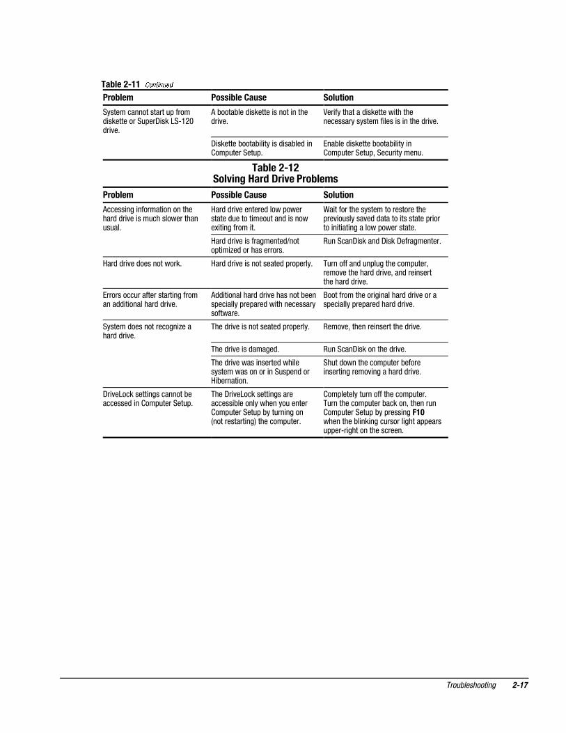
��-����)�,���5�%�#��-���'����-����
���-��� �����-���$���� ������
������� ��)�������$����)���$� ����� ��*
(��������� ���"�����)���� � � ���$**
�����������������������������������*
B" ������6B" �����������)���� � � ���$
������)����������)���$���$����"����"�� ������� ����������������'��������"��#����,���#������$*
� -�����)����$ ��)��$* ������!A!,����������������3��������� ������� ��������� -*
��)�$$�$��"��� �����#�$������#"�������)���$� ��$ ��)��$*
�"��������"��� ��� �������"���$��
������!A����?9�������)��������"�������"��� �����$���)�$$�$��"��� ����#�$*
��-����)�3���5�%���'������-����
���-��� �����-���$���� ������
&�$���������������� ��* ������)���������� �����������#������ ������������$��� �������*
��������������"�����������#������)��� ��#��#�������������$*
����7� � �����������)���$ ��)��$*
- ��)��� ����7� � ��!
1. �������������� ���� ����� ���������������������&�$���*
2. :������������������)�������&�$�������#��� ���#���'�������- �� ������#��� ��*
:��������&������� ������)�������- �� ������#��� ���#���'�����������)�3��)���$��� ������� �������������� � ��*�������J?1'�?1I'����..?1���������$��#,$����� ������$ ��)���������� � ��*
������ ���� �������3���� %������� ��������#������ ��*
����������� ��������������� ��*
&�$����������#��$ �� &�$��� ����������"#����������� �����������*
������������#"�����������"#*��� ���;" �����#�� � ������ ����������$���')���"���������������%��)�������)��$*
Continued
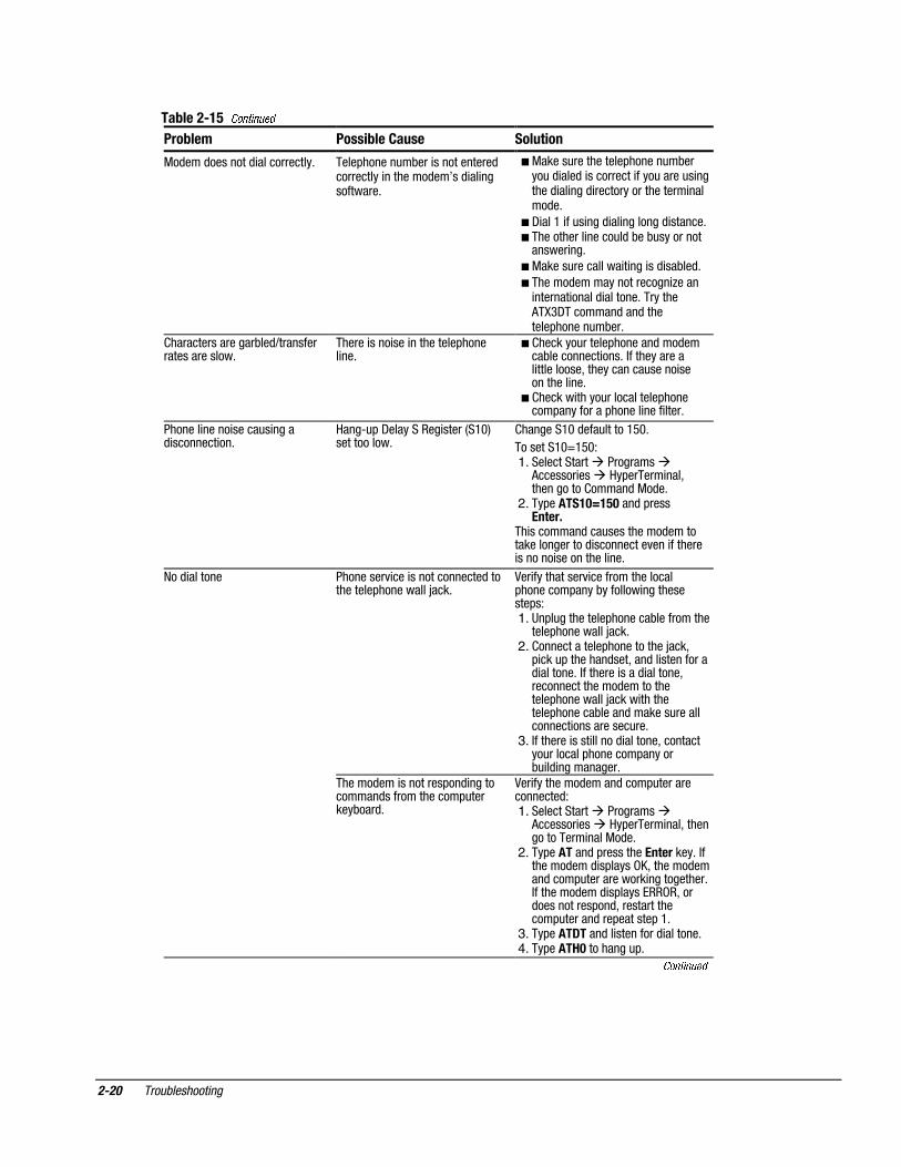
���� ������������
���-����)�3��Continued
���-��� �����-���$���� ������
&�$���$��������$ ������������* ����#������"�)��� ������������$���������� ��������$��H��$ �� ����������*
� &�����"�����������#������"�)����"�$ ���$� ���������� ����"�����"� ������$ �� ���$ ������������������� �����$�*
� - ���.� ��"� ���$ �� ��������$ ������*� ����������� �����"�$�)��)"���������
������ ��*
� &�����"���������� � ��� ��$ ��)��$*
� ������$����������������� +���� ������� �����$ �������*��������(�K0-��������$���$��������#������"�)��*
� �����������������)��$6����������������������*
������� ���� ��� ����������#����� ��*
� �������"������#�������$���$����)���������� ���*�������������� ����������'������������"����� ���������� ��*
� ������ �����"������������#�������#����������#������ ���� ����*
������� ����� �����"� ����$ �������� ��*
���,"#�-���������� �����4�.15�����������*
�������.1�$���"������.91*
��������[email protected]!1. �������������������������
(������� ������#������ ���'����������� �����$�&�$�*
2. ��#������"B�3"���$�#���� ���
�� ��������$���"����������$��������������������$ ����������%��� ������� ������� ����������� ��*
���$ ������� ���������% ��� ��������������$�����������#����������C���*
A�� �����������% �����������������#��������#����)�������� �����������#�!1. ��#�"����������#�������)�����������
����#����������C���*2. �������������#������������C���'
# ���"#��������$���'���$�� ����������$ �������*��������� ����$ �������'����������������$�������������#����������C����� ����������#�������)�����$�������"������������� �����������"��*
3. �������� ���� ������$ �������'����������"��������#��������#������)" �$ ����������*
������$��� ���������#��$ �����������$��������������#"������)���$*
A�� ���������$�����$����#"���������������$!1. �������������������������
(������� ������#������ ���'��������������� ����&�$�*
2. ��#�������$�#��������� ������*��������$���$ �#������2'�������$����$����#"������������ �����������*��������$���$ �#����������'���$�����������#��$'���������������#"������$���#�������#�.*
3. ��#����.����$�� ���������$ �������*4. ��#����@"���������"#*
Continued
������������ ����
��-����)�3��Continued
���-��� �����-���$���� ������
&�$���$������������������� �������#��$*
� ������$ � ���� ����"���������� ������������"��������� �����������"##��������� ��������������#��$�*
�%����"������#������ ���������$�)���"������������#��������% ���#��% $��*
����$ �� ��������������������#�����"�)��������������% �����"�����"� ��*
(�������$�% ��������"������#����� �������)����"� ��� �����������*
����"#�����3���� �������#�������$$ �������������������$�% ������������)��"� ����������������#������ ��'�������$ ��*
�������% ������� ��������$�$��������"##����9=2�����"##������� ����#�� )���9=2� �#�������� ��*
��������$��$� ����������$���"##���������A*81��������$��$����9=2���$����� ���)������$���#�� ) � ������29=���3*����� �$��������������% ������% $���4��5�����"##�����A*81����29=���3�#��������'���������� ��#�;�7�)�� ��������*���#�;*���*
������ ���� ��������������#����� ��*
����9=2�#�������������� ���������$���� ��������)��������������#��$� ����������#������ ��� �������� ��������� ��,�#��$�������� ��*
����"� ���������������#������ ��*
�������������,"#�-���������� ����!
1. �����������������������(������� �����#������ ���*
2. ������ �����$�&�$�'���#�(��[email protected]'������#����� ��*
��� ���� ��������$���"���������$���������������������$ ���������%��� �������� ������� ����������� ��*
��������#������ ���$��������"##����9=2� �#�������� ��*
����9=2�#����������;" ����������������#������ �������� ������������������������,��,$ � �������%��� ��*
����������� ���������������������� ��*
��-����)�7���5�%��$�$��'����-����
���-��� �����-���$���� ������
��#"����$��������)��#�������� � ��$� �� ������$*
� � ��$� ������ ������$�#��#����* ������ ����� ����������$*����"������������ � ��$� �� ������$� ��������������� ����� ��*��������������$����������#��%����$�������������# ��*
�#������������"���$��������%��"�� ���"���$�$���*
($C"�������%��"��������������������#"���*
� � ��$�������$�$� %��� ������ & (����#� ���*
���������� ������� � ��$�������$�"������"���� �� ��#�;�� � ��$#��������*
Continued
���� ������������
��-����)�7��Continued
���-��� �����-���$���� ������
��#"����)��#������������������� � ��$� �� ������$*
�������#"����)��#��������� �$ ������������� � ��$� ������� +�$�)"������#��#�������� �"��$*
�������������� � ��$�����)��"��$'� �����)���������������#���������� � � �����"#�#����$"��*�:����������� � ��$���"����"���G�� ����"�� �������������� ��������$�$� %�����$��� ������ ���� � ��$,�#�� � ��$� %��������������������$*
��������� � ��$�$������������* ����������$� %����������� �������$�4�"���$���5*
������������� ����"�� �������������� �������� � ��$���������������%��$������� ������� ������ ������ ��������������$� %���*
� � ��$� �������"���� ������$���� �"#� $��$���*
���"�������� � ��$� �� ������$���������*
��������� � ��$����$� %��� ������ & (����#� ���*
���������� ������� � ��$�������$�"������"���� �� ��#�;�� � ��$#��������*
��������� � ��$�$������������* ��(&���$��������������� ��$����;" �����������������$$� %������)�����$�$*
&���������$�����������)���������$"� ���-����������$��$� %���*
F�"�������� ������������������������� � ��$�"� ������������$� %��������*
����"������"�� ���7 �$����89'�����������$� %������������ ������� �-�% ���&������
����"������"�� ���7 �$�������<*1'�����������$� %������������ ����������"������� ������������*
����� � ��$� ��������������$* :�������������$�'��"��& :��&(�� �&�,-���&�$����������������� � ��$*:���(�(����$�'��"��(�(��'�������"�& :��&(�� ��&�,-���&�$���������������� � ��$*
�������$� �������"##����$* ���������� ������� � ��$�������$�"������"���� �� ��#�;�� � ��$#��������*
�����������$�'��"��������(&'�$���������� �������3#��� ���)���*
�������������������$� ���������#"���*
������������ ����
��-����)�8���5�%���&������-����
���-��� �����-���$���� ������
��#"����� ��������"�����* �������� ��$ �������$���$���#"���� ��������������$�����#�������"���*
� ����������)�������#���*
� ��#���������)�������#���*
� ��������������#"�����������3������#�������"���*
� ��������� ��$ �������$���$���)�����������3�������#�������"�������"�#�"���$*
����"����������)����������� ���������#"������$������3�������#������"��������#�"���$� ��#��#����*
� ��#"�����"���$������ ��� �����������"������$�$*
� ��#"���� � � ���$�)���"��������� � ��������)����������$ � ��*
� ����������)�������#���*
� ��#���������)�������#���*
� ��������������#"�����������3������#�������"���*
� ��������#"���� � � ���$ )����� �����������"���,$�� ��$� ���"���3# ��$*
��"�������������#"���*
���-����)�:���5�%��/�������-����
����-��� ������-���$���� �������
� ����������������#"����$ �#�������$ �*
� ��#"���� �� ��$ ������ ���*
�����)� ���������������� ���������#��#����*
�&�%���������#"��������$C"�������������*
�($C"�������)� ����������������)�#���� �������!E!�"��������*
� �F�"�������%�������������%������������)���� ���"� � ��� �������$*
������������������������������������*
� ��������� ���"������ � � ���$* ������������������� ��������������*
� �������� � � ���$��"�#��$��������"���,$�� ��$�� ���"���3# ��$*
������������"�#��$�)"���������3 ��"�#��$*
� � ��#"���� � � ���$�������)�������"�#��$���� )����� ��*
� ��#���������)�������#������$��3 ��"�#��$���� )����� ��*
� ��������������#"�����������3������#�������"������$��3 ���"�#��$��� )����� ��*
� �������&���������'��� ������������"�#��$���$� )����� ��' ��$ ��)��$���$�����)�������#�������$ �������$*
� ��#���������)�������#������$��"������������#"���*
� ��������������#"�����������3������#�������"������$��"������������#"���*
��#"����������� ��)�������$�3���������� ����$ �#���� ������� ��*
- �#���������� ����$��������3���������� ���*
������!A!,����$ �#���� ������� ������������#"����������L�#�����!A!,��� �����$ �#���� ������� ��� �"������"�������)�����������*
- �#������ ���� ����"��* ��#������� ���*
!A!,�����������) ��� ���$��������� ����)������� ����������$�3�������$ �#����*
������������$ �#����$�% ��� �������������$�#��#����*
�������"��������� ����������"�����������3�������$�% ��� ����������$#��#����*

���� ������������
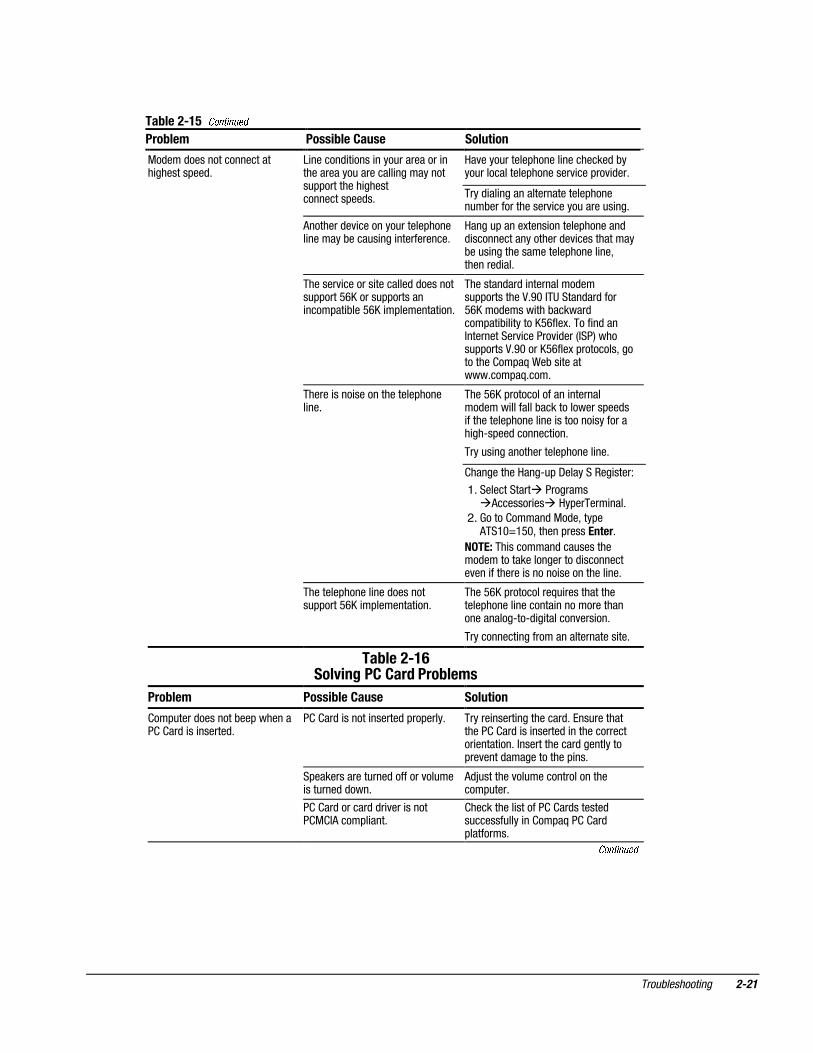
��-����)�;���5�%�4�0����-����
���-��� �����-���$���� ������
�3�������$�% �����������$�������������������$������������*
�����#���� ����������� � ���3�������$�% ������������$�)������������� ������ ������ ���"$��������������������")��������� ����� �����$��������������������)���$���$�����#� �� ���$�% ���������� ������������$�� ��*
��$"��������"�)��������������$�3�����������$�% ������������������������")���������� ����� ��'���$��������������������)���$���$�����#� �� ��$�% ����������� ������������$�� ��*
�3�������$�% �����������$�����������������$������������$"� ��������"#�4)������7 �$���89����$�5*
-"� ��������"#'����������� ��������"##����$�)����������#���*������� �������� ���"$�������������������")���������� ����� �����$��������������������)���$���$����#� �� ���$�% ����������� �����������$�� ��*
���������3�������$�% �������������7 �$����89����7 �$����8>�������$�$*
��$"��������"�)��������������$�3�����������$�% ������������������������")���������� ����� ��'���$��������������������)���$���$�����#� �� ��$�% ����������� ������������$�� ��*
�3�������$�% ���� ��������� ����$���������*
(��"�#�����$��")� ����������$�����������"�#�����$��")*
���������#�����$��")�*
&�����"������������"�#�����$��")����� ���$ ������#����$�$�)��#�����$�")�� ������������� �*
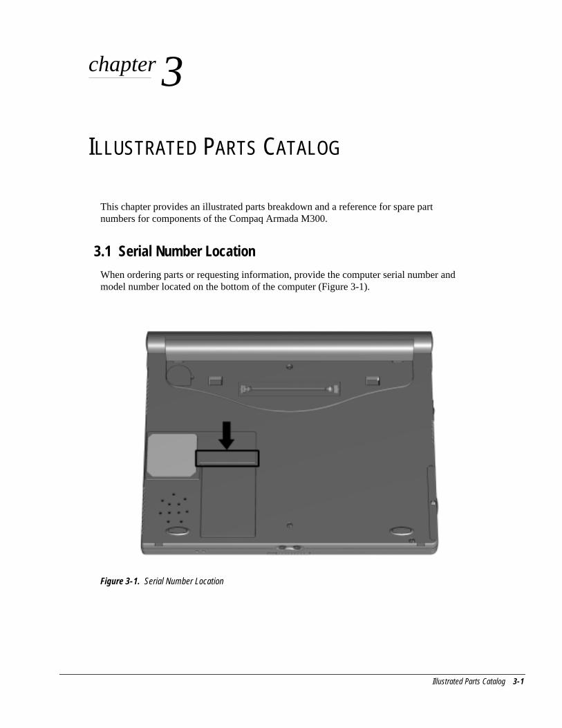
Illustrated Parts Catalog 3-1
chapter 3
ILLUSTRATED PARTS CATALOG
This chapter provides an illustrated parts breakdown and a reference for spare partnumbers for components of the Compaq Armada M300.
3.1 Serial Number LocationWhen ordering parts or requesting information, provide the computer serial number andmodel number located on the bottom of the computer (Figure 3-1).
Figure 3-1. Serial Number Location
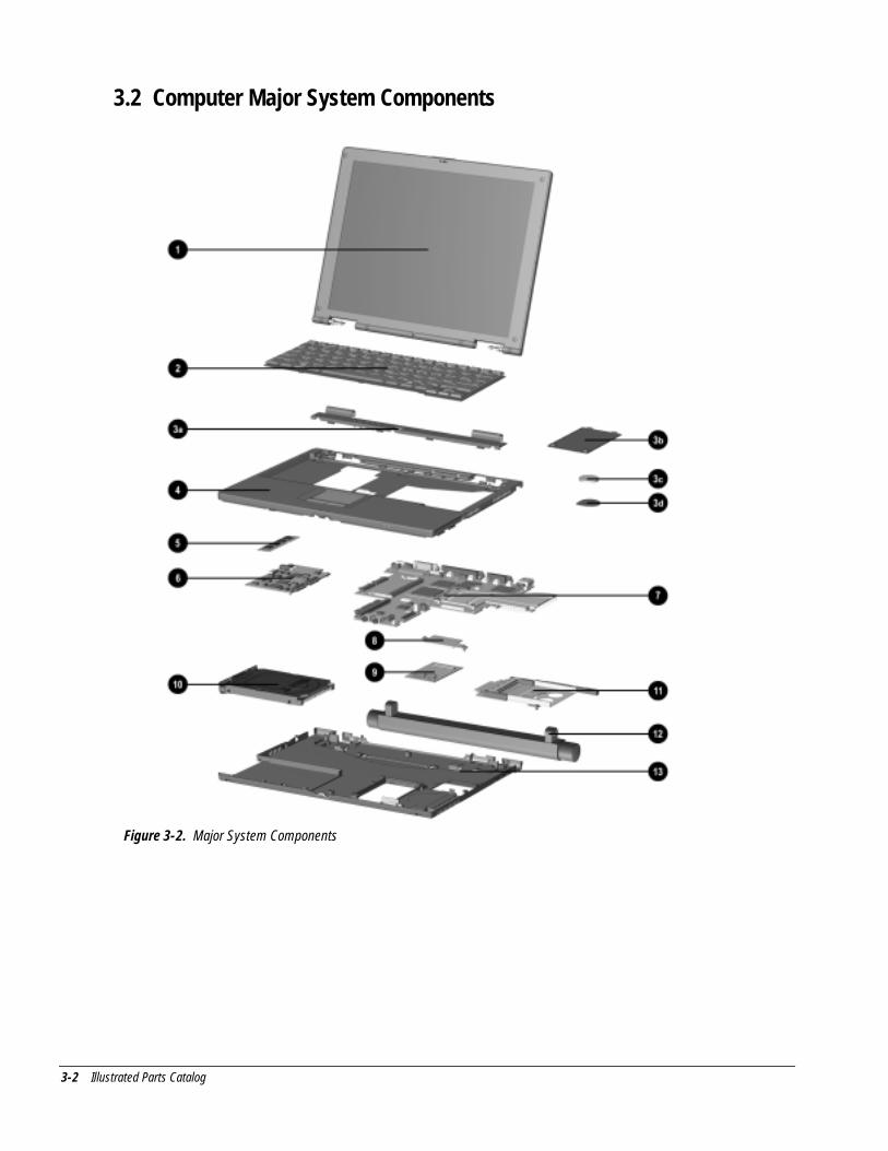
3-2 Illustrated Parts Catalog
3.2 Computer Major System Components
Figure 3-2. Major System Components
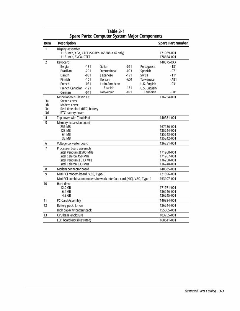
Illustrated Parts Catalog 3-3
Table 3-1Spare Parts: Computer System Major Components
Item Description Spare Part Number 1 Display assembly
11.3-inch, XGA, CTFT (SKU#’s 165288-XXX only)11.3-inch, SVGA, CTFT
171969-001178654-001
2 Keyboard 140375-XXXBelgianBrazilianDanishFinnishFrenchFrench CanadianGerman
-181-201-081-101-051-121-041
ItalianInternationalJapaneseKoreanLatin American
SpanishNorwegian
-061-003-191-AD1
-161-091
PortugueseSpanishSwissTaiwaneseU.K. EnglishU.S. English/
Canadian
-131-071-111-AB1-031
-001
3a 3b 3c 3d
Miscellaneous Plastic KitSwitch coverModem coverReal time clock (RTC) batteryRTC battery cover
136254-001
4 Top cover with TouchPad 140381-001 5 Memory expansion board
256 MB128 MB 64 MB 32 MB
167136-001135244-001135243-001135242-001
6 Voltage converter board 136251-001 7 Processor board assembly
Intel Pentium III 500 MHzIntel Celeron 450 MHzIntel Pentium II 333 MHzIntel Celeron 333 MHz
171968-001171967-001136250-001136248-001
8 Modem connector board 140385-001 9 Mini PCI modem board, V.90, Type-I
Mini PCI combination modem/network interface card (NIC), V.90, Type-I121896-001153107-001
10 Hard drive12.0 GB 6.4 GB 4.3 GB
171971-001136246-001136245-001
11 PC Card Assembly 140384-00112 Battery pack, Li-ion
High capacity battery pack136244-001155065-001
13 CPU base enclosure 103755-001LED board (not illustrated) 168641-001
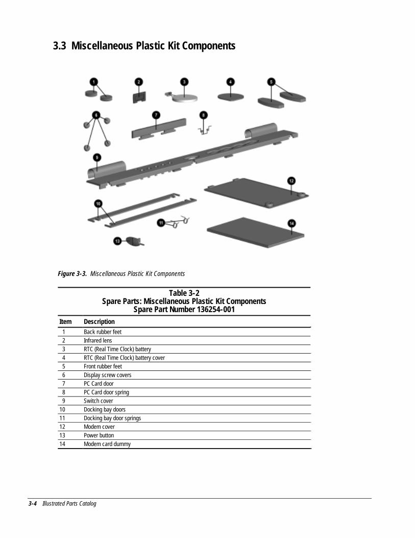
3-4 Illustrated Parts Catalog
3.3 Miscellaneous Plastic Kit Components
Figure 3-3. Miscellaneous Plastic Kit Components
Table 3-2Spare Parts: Miscellaneous Plastic Kit Components
Spare Part Number 136254-001Item Description 1 Back rubber feet 2 Infrared lens 3 RTC (Real Time Clock) battery 4 RTC (Real Time Clock) battery cover 5 Front rubber feet 6 Display screw covers 7 PC Card door 8 PC Card door spring 9 Switch cover10 Docking bay doors11 Docking bay door springs12 Modem cover13 Power button14 Modem card dummy
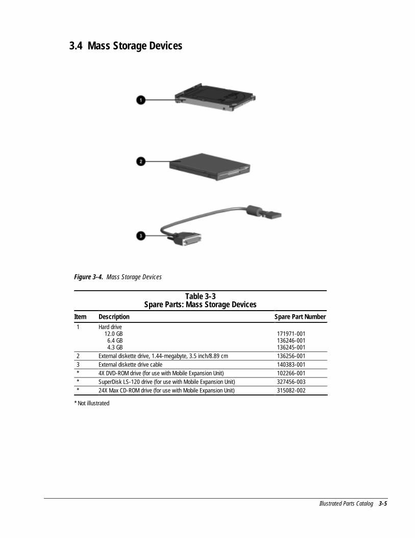
Illustrated Parts Catalog 3-5
3.4 Mass Storage Devices
Figure 3-4. Mass Storage Devices
Table 3-3Spare Parts: Mass Storage Devices
Item Description Spare Part Number1 Hard drive
12.0 GB 6.4 GB 4.3 GB
171971-001136246-001136245-001
2 External diskette drive, 1.44-megabyte, 3.5 inch/8.89 cm 136256-0013 External diskette drive cable 140383-001* 4X DVD-ROM drive (for use with Mobile Expansion Unit) 102266-001* SuperDisk LS-120 drive (for use with Mobile Expansion Unit) 327456-003* 24X Max CD-ROM drive (for use with Mobile Expansion Unit) 315082-002
* Not illustrated
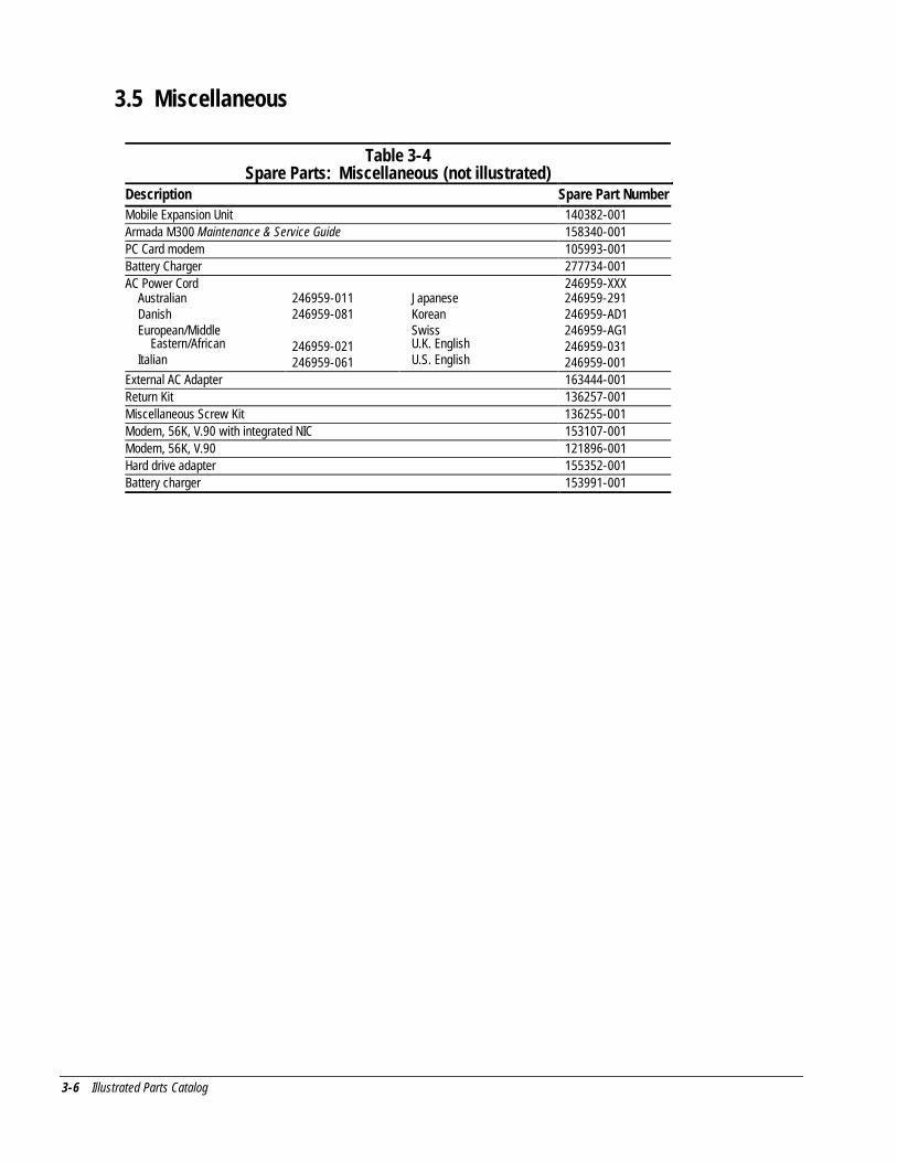
3-6 Illustrated Parts Catalog
3.5 Miscellaneous
Table 3-4Spare Parts: Miscellaneous (not illustrated)
Description Spare Part NumberMobile Expansion Unit 140382-001Armada M300 Maintenance & Service Guide 158340-001PC Card modem 105993-001Battery Charger 277734-001AC Power Cord 246959-XXX
AustralianDanishEuropean/Middle
Eastern/AfricanItalian
246959-011246959-081
246959-021246959-061
JapaneseKoreanSwissU.K. EnglishU.S. English
246959-291246959-AD1246959-AG1246959-031246959-001
External AC Adapter 163444-001Return Kit 136257-001Miscellaneous Screw Kit 136255-001Modem, 56K, V.90 with integrated NIC 153107-001Modem, 56K, V.90 121896-001Hard drive adapter 155352-001Battery charger 153991-001
Removal and Replacement Preliminaries 4-1
chapter 4
REMOVAL AND REPLACEMENTPRELIMINARIES
This chapter provides essential information for proper and safe removal andreplacement service.
4.1 Tools Required
You will need the following tools to complete the removal and replacement procedures:
■ Magnetic Torx T-8 screwdriver (for all screws unless otherwise specified)
■ 9/32-inch socket for bushing guides
4.2 Service Considerations
Listed below are some of the considerations that you should keep in mind duringdisassembly and assembly procedures.
Plastic Parts
Using excessive force during disassembly and reassembly can damage plastic parts. Usecare when handling the plastic parts. Apply pressure only at the points designated in themaintenance instructions.
IMPORTANT: As you remove each subassembly from the computer, place it (and allaccompanying screws) away from the work area to prevent damage.
4-2 Removal and Replacement Preliminaries
Cables and Connectors
Cables must be handled with extreme care to avoid damage. Apply only the tensionrequired to unseat or seat the cables during removal and insertion. Handle cables by theconnector whenever possible. In all cases, avoid bending, twisting, or tearing cables.Ensure that cables are routed in such a way that they cannot be caught or snagged byparts being removed or replaced. Handle flex cables with extreme care; they tear easily.
CAUTION: When servicing the computer, ensure that cables are placed in theirproper location during the reassembly process. Improper cable placement candamage the computer.
4.3 Preventing Damage to Removable Drives
Removable drives are fragile components that must be handled with care. To preventdamage to the computer or a removable drive, or loss of information, observe theseprecautions:
■ Before removing or inserting a hard drive, shut down the computer. If you areunsure whether the computer is off or in Hibernation, turn the computer on, thenshut it down.
■ Before removing a diskette drive, CD-ROM drive, SuperDisk LS-120 drive, or aDVD-ROM drive, ensure that a diskette or disc is not in the drive. Ensure that thedrive tray is closed.
■ Before handling a drive, ensure that you are discharged of static electricity. Whilehandling a drive, avoid touching the connector.
■ Handle drives on surfaces that have at least one inch of shock-proof foam.
■ Avoid dropping drives from any height onto any surface.
■ Do not use excessive force when inserting a drive into a drive bay.
■ Avoid exposing a hard drive to products that have magnetic fields such as monitorsor speakers.
■ Avoid exposing a drive to temperature extremes or to liquids.
■ If a drive must be mailed, ship it in a suitable form of protective packaging.Shipping the drive in standard packaging may not cushion it from destructive shock,vibration, temperature, or humidity. Place a mailing label with the wording“Fragile: Handle With Care” on the mailer.
■ After the hard drive has been removed from the computer, avoid turning the harddrive and tray upside down. The drive is not secured to the tray and can fall out.
■ Do not place labels on the ventilation area on the hard drive.
■ Heed the labels on the hard drive.

Removal and Replacement Preliminaries 4-3
4.4 Preventing Electrostatic Damage
Many electronic components are sensitive to electrostatic discharge (ESD). Circuitrydesign and structure determine the degree of sensitivity. Networks built into manyintegrated circuits provide some protection, but in many cases the discharge containsenough power to alter device parameters or melt silicon junctions.
A sudden discharge of static electricity from a finger or other conductor can destroystatic-sensitive devices or microcircuitry. Often the spark is neither felt nor heard, butdamage occurs. An electronic device exposed to electrostatic discharge may not beaffected at all and can work perfectly throughout a normal cycle. Or it may functionnormally for a while, then degrade in the internal layers, reducing its life expectancy.
Packaging and Transporting Precautions
Use the following grounding precautions when packaging and transporting equipment:
■ To avoid hand contact, transport products in static-safe containers such as tubes,bags, or boxes.
■ Protect all electrostatic-sensitive parts and assemblies with conductive or approvedcontainers or packaging.
■ Keep electrostatic-sensitive parts in their containers until they arrive at static-freeworkstations.
■ Place items on a grounded surface before removing them from their container.
■ Always be properly grounded when touching a sensitive component or assembly.
■ Place reusable electrostatic-sensitive parts from assemblies in protective packagingor non-conductive foam.
■ Use transporters and conveyers made of antistatic belts and roller bushings. Ensurethat mechanized equipment used for moving materials is wired to ground, and thatproper materials are selected to avoid static charging. When grounding is notpossible, use an ionizer to dissipate electric charges.
4-4 Removal and Replacement Preliminaries
Workstation Precautions
Use the following grounding precautions at workstations:
■ Cover the workstation with approved static-dissipative material (refer to Table 4-2later in this chapter).
■ Use a wrist strap connected to a properly grounded work surface and use properlygrounded tools and equipment.
■ Use field service tools, such as cutters, screwdrivers, and vacuums that areconductive.
■ When using fixtures that must directly contact dissipative surfaces, use fixturesmade of static-safe materials only.
■ Keep work area free of nonconductive materials such as ordinary plastic assemblyaids and Styrofoam.
■ Handle electrostatic-sensitive components, parts, and assemblies by the case orPCM laminate. Handle them only at static-free workstations.
■ Avoid contact with pins, leads, or circuitry.
■ Turn off power and input signals before inserting or removing connectors or testequipment.
Removal and Replacement Preliminaries 4-5
Grounding Equipment and Methods
Grounding equipment must include either a wrist strap or a foot strap at a groundedworkstation.
■ When seated, wear a wrist strap connected to a grounded system. Wrist straps areflexible straps with a minimum of one megohm ±10% resistance in the groundcords. To provide proper ground, a strap must be worn snug against the skin. Ongrounded mats with banana-plug connectors, connect a wrist strap with alligatorclips.
■ When standing, use foot straps and a grounded floor mat. Foot straps (heel, toe, orboot straps) can be used at standing workstations and are compatible with mosttypes of shoes or boots. On conductive floors or dissipative floor mats, use footstraps on both feet with a minimum of one-megohm resistance between the operatorand ground. To be effective, the conductive strips must be worn in contact with theskin.
Other grounding equipment recommended for use in preventing electrostatic damageinclude:
■ Antistatic tape
■ Antistatic smocks, aprons, or sleeve protectors
■ Conductive bins and other assembly or soldering aids
■ Non-conductive foam
■ Conductive tabletop workstations with ground cord of one-megohm resistance
■ Static-dissipative table or floor mats with hard tie to ground
■ Field service kits
■ Static awareness labels
■ Material-handling packages
■ Non-conductive plastic bags, tubes, or boxes
■ Metal tote boxes
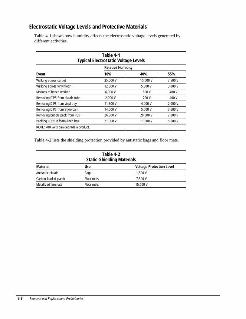
4-6 Removal and Replacement Preliminaries
Electrostatic Voltage Levels and Protective Materials
Table 4-1 shows how humidity affects the electrostatic voltage levels generated bydifferent activities.
Table 4-1Typical Electrostatic Voltage Levels
Relative Humidity
Event 10% 40% 55%
Walking across carpet 35,000 V 15,000 V 7,500 V
Walking across vinyl floor 12,000 V 5,000 V 3,000 V
Motions of bench worker 6,000 V 800 V 400 V
Removing DIPS from plastic tube 2,000 V 700 V 400 V
Removing DIPS from vinyl tray 11,500 V 4,000 V 2,000 V
Removing DIPS from Styrofoam 14,500 V 5,000 V 3,500 V
Removing bubble pack from PCB 26,500 V 20,000 V 7,000 V
Packing PCBs in foam-lined box 21,000 V 11,000 V 5,000 V
NOTE: 700 volts can degrade a product.
Table 4-2 lists the shielding protection provided by antistatic bags and floor mats.
Table 4-2Static-Shielding Materials
Material Use Voltage Protection Level
Antistatic plastic Bags 1,500 V
Carbon-loaded plastic Floor mats 7,500 V
Metallized laminate Floor mats 15,000 V
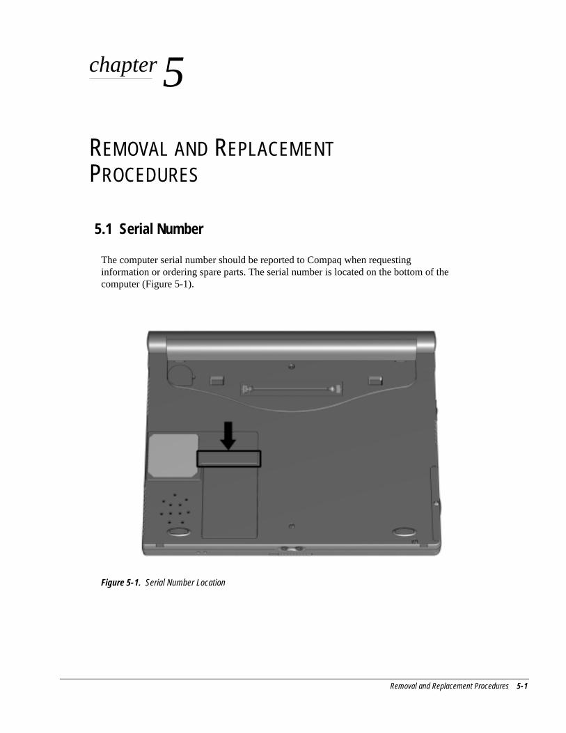
Removal and Replacement Procedures 5-1
chapter 5
REMOVAL AND REPLACEMENTPROCEDURES
5.1 Serial Number
The computer serial number should be reported to Compaq when requestinginformation or ordering spare parts. The serial number is located on the bottom of thecomputer (Figure 5-1).
Figure 5-1. Serial Number Location

5-2 Removal and Replacement Procedures
5.2 Disassembly Reference ChartUse the chart below to determine the section number to be referenced when removingcomponents from the computer.
5.3 Disconnecting the Computer from the Mobile Expansion Unit
5.4 Disconnecting the Computer
5.5 Preparing the Computer for Disassembly
5.6 Battery Packs
Removing the Battery Pack
Replacing the Battery Pack
5.7 Hard Drives
Removing a Hard Drive
Inserting a Hard Drive
5.8 PC Cards
Removing a PC Card
Inserting a PC Card
5.9 Modem or Modem/NIC Card
5.10 Real Time Clock Battery
5.11 Keyboard
5.12 Memory Expansion
Removing Memory Expansion Boards
Installing Memory Expansion Boards
5.13 Switch Cover
5.14 Display Assembly
5.15 Top Cover with TouchPad
5.16 Voltage Converter Board
5.17 Modem Connector Board
5.18 PC Card Connector
5.19 Processor/System Board Assembly
Figure 5-2. Disassembly Reference Chart
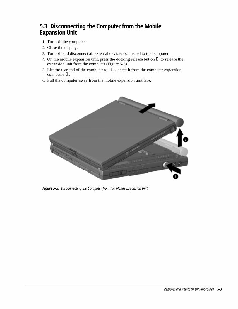
Removal and Replacement Procedures 5-3
5.3 Disconnecting the Computer from the MobileExpansion Unit
1. Turn off the computer.2. Close the display.3. Turn off and disconnect all external devices connected to the computer.4. On the mobile expansion unit, press the docking release button ➊ to release the
expansion unit from the computer (Figure 5-3).5. Lift the rear end of the computer to disconnect it from the computer expansion
connector ➋ .6. Pull the computer away from the mobile expansion unit tabs.
Figure 5-3. Disconnecting the Computer from the Mobile Expansion Unit
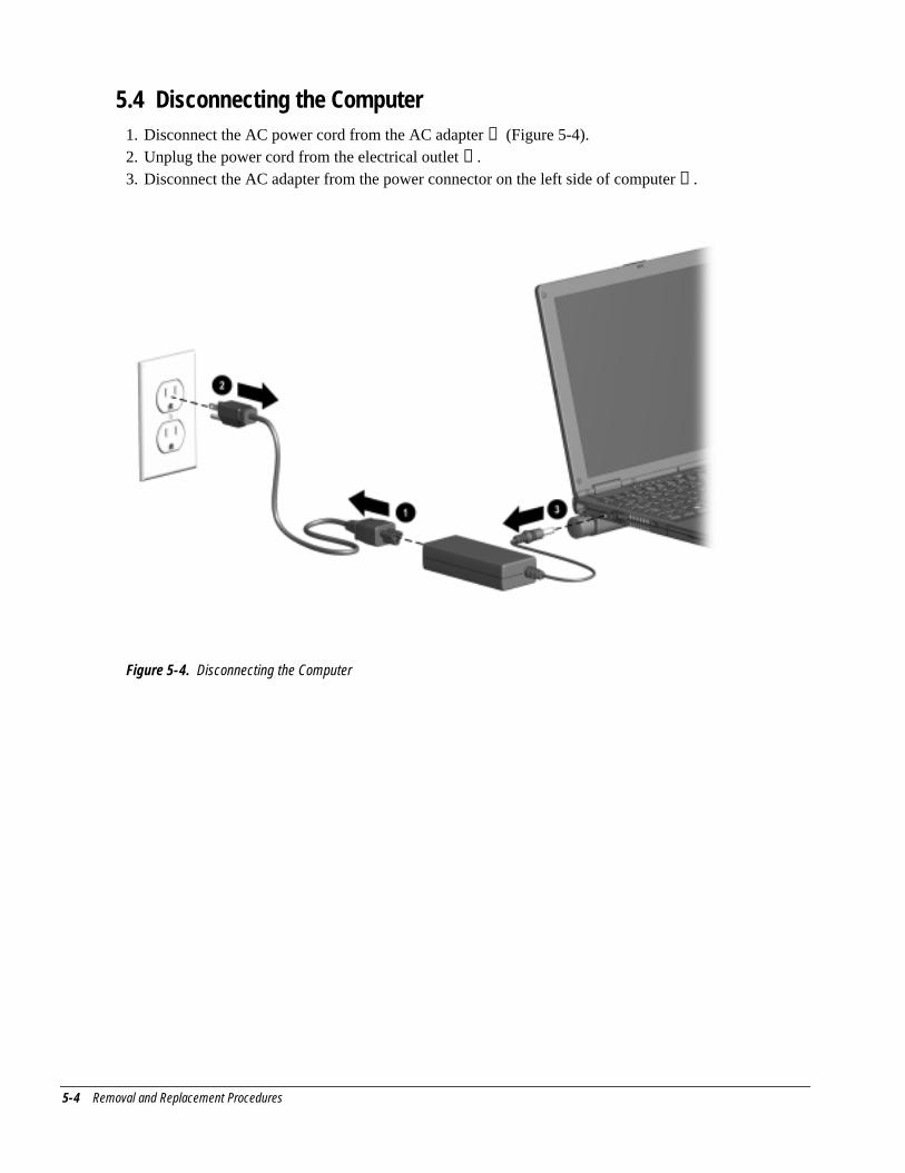
5-4 Removal and Replacement Procedures
5.4 Disconnecting the Computer1. Disconnect the AC power cord from the AC adapter ➊ (Figure 5-4).2. Unplug the power cord from the electrical outlet ➋ .3. Disconnect the AC adapter from the power connector on the left side of computer ➌ .
Figure 5-4. Disconnecting the Computer
Removal and Replacement Procedures 5-5
5.5 Preparing the Computer for Disassembly1. Disconnect the computer from the mobile expansion unit.2. Shut down the computer.3. Disconnect the AC adapter and all external devices connected to the computer.4. Remove the battery pack (Section 5.6).
CAUTION: Failure to disconnect the AC Adapter from the computer and to remove thebattery pack before removing and installing internal components can damage theequipment.
5. Remove the hard drive (Section 5.7).6. Remove all PC Cards (Section 5.8).
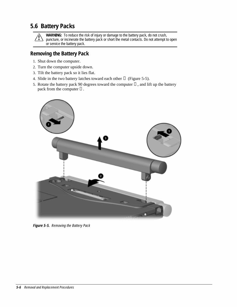
5-6 Removal and Replacement Procedures
5.6 Battery Packs
! WARNING: To reduce the risk of injury or damage to the battery pack, do not crush,puncture, or incinerate the battery pack or short the metal contacts. Do not attempt to openor service the battery pack.
Removing the Battery Pack1. Shut down the computer.2. Turn the computer upside down.3. Tilt the battery pack so it lies flat.4. Slide in the two battery latches toward each other ➊ (Figure 5-5).5. Rotate the battery pack 90 degrees toward the computer ➋ , and lift up the battery
pack from the computer ➌ .
Figure 5-5. Removing the Battery Pack
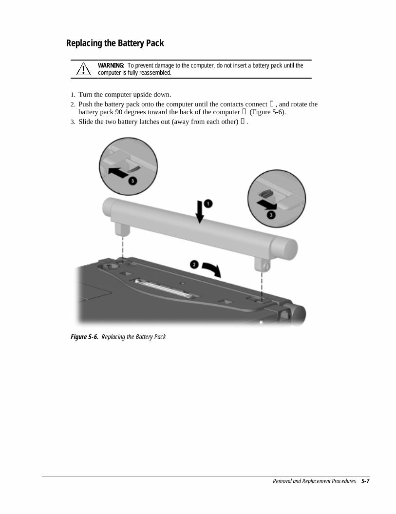
Removal and Replacement Procedures 5-7
Replacing the Battery Pack
! WARNING: To prevent damage to the computer, do not insert a battery pack until thecomputer is fully reassembled.
1. Turn the computer upside down.2. Push the battery pack onto the computer until the contacts connect ➊ , and rotate the
battery pack 90 degrees toward the back of the computer ➋ (Figure 5-6).3. Slide the two battery latches out (away from each other) ➌ .
Figure 5-6. Replacing the Battery Pack
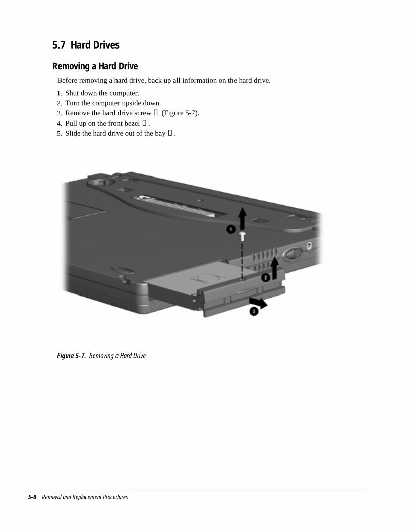
5-8 Removal and Replacement Procedures
5.7 Hard Drives
Removing a Hard DriveBefore removing a hard drive, back up all information on the hard drive.
1. Shut down the computer.2. Turn the computer upside down.3. Remove the hard drive screw ➊ (Figure 5-7).4. Pull up on the front bezel ➋ .5. Slide the hard drive out of the bay ➌ .
Figure 5-7. Removing a Hard Drive
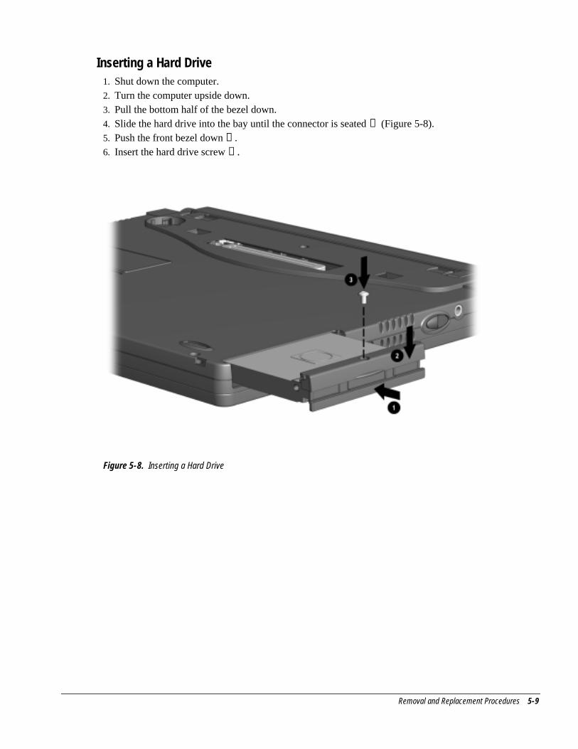
Removal and Replacement Procedures 5-9
Inserting a Hard Drive1. Shut down the computer.2. Turn the computer upside down.3. Pull the bottom half of the bezel down.4. Slide the hard drive into the bay until the connector is seated ➊ (Figure 5-8).5. Push the front bezel down ➋ .6. Insert the hard drive screw ➌ .
Figure 5-8. Inserting a Hard Drive
5-10 Removal and Replacement Procedures
5.8 PC CardsThe procedure for removing PC Cards varies with the operating system being used andwith the kind of PC Card being removed.
In Windows 95 or Windows 98—
■ If you insert a PC Card while the computer is on, the computer beeps twice when thecard is ready for use.
■ If you remove a PC Card while the computer is on, the computer beeps twice whenthe card is removed.
■ When a PC Card is in the system, the PC Card icon displays on the taskbar.
In Windows NT 4.0 with CardWare from Compaq—
■ If you insert a PC Card while the computer is on, the computer beeps three timeswhen the card is recognized.
■ If you remove a PC Card while the computer is on, the computer beeps three timeswhen the card is removed.
■ The PC Card icon displays in the taskbar whether or not a PC Card is in the system.
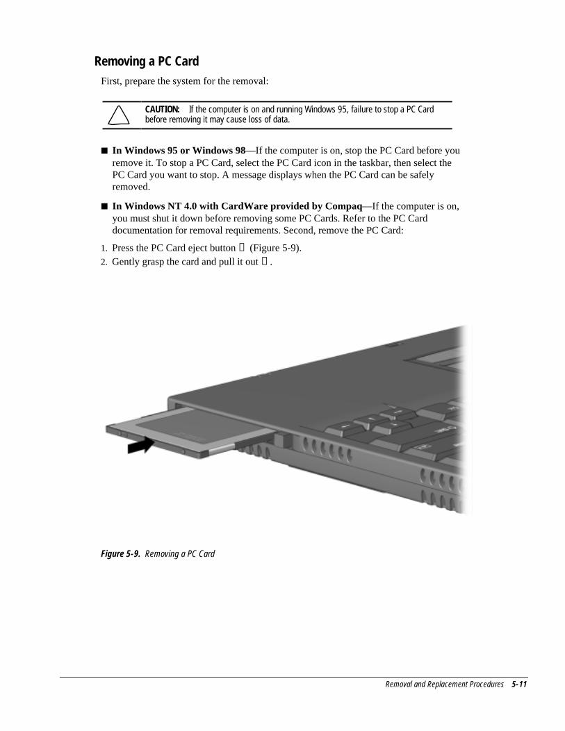
Removal and Replacement Procedures 5-11
Removing a PC CardFirst, prepare the system for the removal:
CAUTION: If the computer is on and running Windows 95, failure to stop a PC Cardbefore removing it may cause loss of data.
■ In Windows 95 or Windows 98—If the computer is on, stop the PC Card before youremove it. To stop a PC Card, select the PC Card icon in the taskbar, then select thePC Card you want to stop. A message displays when the PC Card can be safelyremoved.
■ In Windows NT 4.0 with CardWare provided by Compaq—If the computer is on,you must shut it down before removing some PC Cards. Refer to the PC Carddocumentation for removal requirements. Second, remove the PC Card:
1. Press the PC Card eject button ➊ (Figure 5-9).2. Gently grasp the card and pull it out ➋ .
Figure 5-9. Removing a PC Card
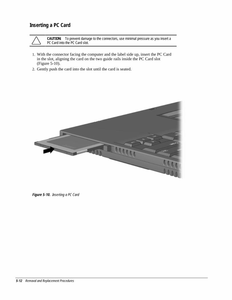
5-12 Removal and Replacement Procedures
Inserting a PC Card
CAUTION: To prevent damage to the connectors, use minimal pressure as you insert aPC Card into the PC Card slot.
1. With the connector facing the computer and the label side up, insert the PC Cardin the slot, aligning the card on the two guide rails inside the PC Card slot(Figure 5-10).
2. Gently push the card into the slot until the card is seated.
Figure 5-10. Inserting a PC Card
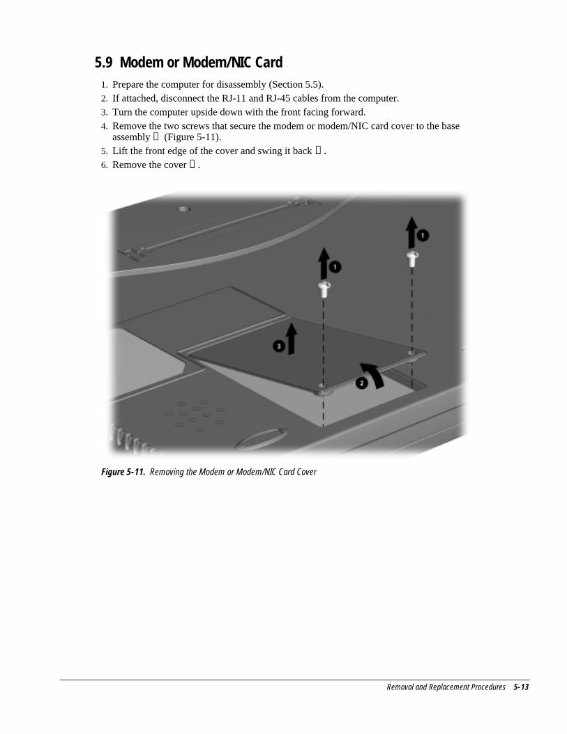
Removal and Replacement Procedures 5-13
5.9 Modem or Modem/NIC Card1. Prepare the computer for disassembly (Section 5.5).2. If attached, disconnect the RJ-11 and RJ-45 cables from the computer.3. Turn the computer upside down with the front facing forward.4. Remove the two screws that secure the modem or modem/NIC card cover to the base
assembly ➊ (Figure 5-11).5. Lift the front edge of the cover and swing it back ➋ .6. Remove the cover ➌ .
Figure 5-11. Removing the Modem or Modem/NIC Card Cover
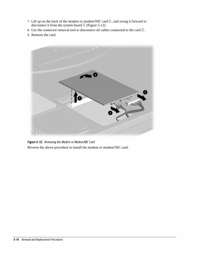
5-14 Removal and Replacement Procedures
7. Lift up on the back of the modem or modem/NIC card ➊ , and swing it forward todisconnect it from the system board ➋ (Figure 5-12).
8. Use the connector removal tool to disconnect all cables connected to the card ➌ .9. Remove the card.
Figure 5-12. Removing the Modem or Modem/NIC Card
Reverse the above procedure to install the modem or modem/NIC card.
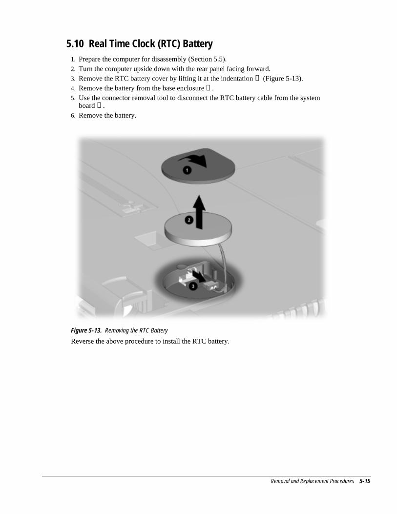
Removal and Replacement Procedures 5-15
5.10 Real Time Clock (RTC) Battery1. Prepare the computer for disassembly (Section 5.5).2. Turn the computer upside down with the rear panel facing forward.3. Remove the RTC battery cover by lifting it at the indentation ➊ (Figure 5-13).4. Remove the battery from the base enclosure ➋ .5. Use the connector removal tool to disconnect the RTC battery cable from the system
board ➌ .6. Remove the battery.
Figure 5-13. Removing the RTC Battery
Reverse the above procedure to install the RTC battery.
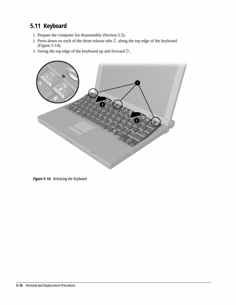
5-16 Removal and Replacement Procedures
5.11 Keyboard1. Prepare the computer for disassembly (Section 5.5).2. Press down on each of the three release tabs ➊ along the top edge of the keyboard
(Figure 5-14).3. Swing the top edge of the keyboard up and forward ➋ .
Figure 5-14. Releasing the Keyboard
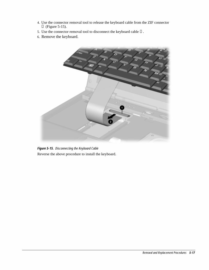
Removal and Replacement Procedures 5-17
4. Use the connector removal tool to release the keyboard cable from the ZIF connector➊ (Figure 5-15).
5. Use the connector removal tool to disconnect the keyboard cable ➋ .6. Remove the keyboard.
Figure 5-15. Disconnecting the Keyboard Cable
Reverse the above procedure to install the keyboard.
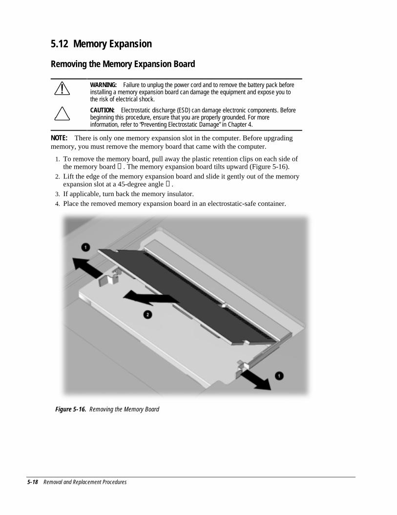
5-18 Removal and Replacement Procedures
5.12 Memory Expansion
Removing the Memory Expansion Board
WARNING: Failure to unplug the power cord and to remove the battery pack beforeinstalling a memory expansion board can damage the equipment and expose you tothe risk of electrical shock.
CAUTION: Electrostatic discharge (ESD) can damage electronic components. Beforebeginning this procedure, ensure that you are properly grounded. For moreinformation, refer to “Preventing Electrostatic Damage” in Chapter 4.
NOTE: There is only one memory expansion slot in the computer. Before upgradingmemory, you must remove the memory board that came with the computer.
1. To remove the memory board, pull away the plastic retention clips on each side ofthe memory board ➊ . The memory expansion board tilts upward (Figure 5-16).
2. Lift the edge of the memory expansion board and slide it gently out of the memoryexpansion slot at a 45-degree angle ➋ .
3. If applicable, turn back the memory insulator.4. Place the removed memory expansion board in an electrostatic-safe container.
Figure 5-16. Removing the Memory Board
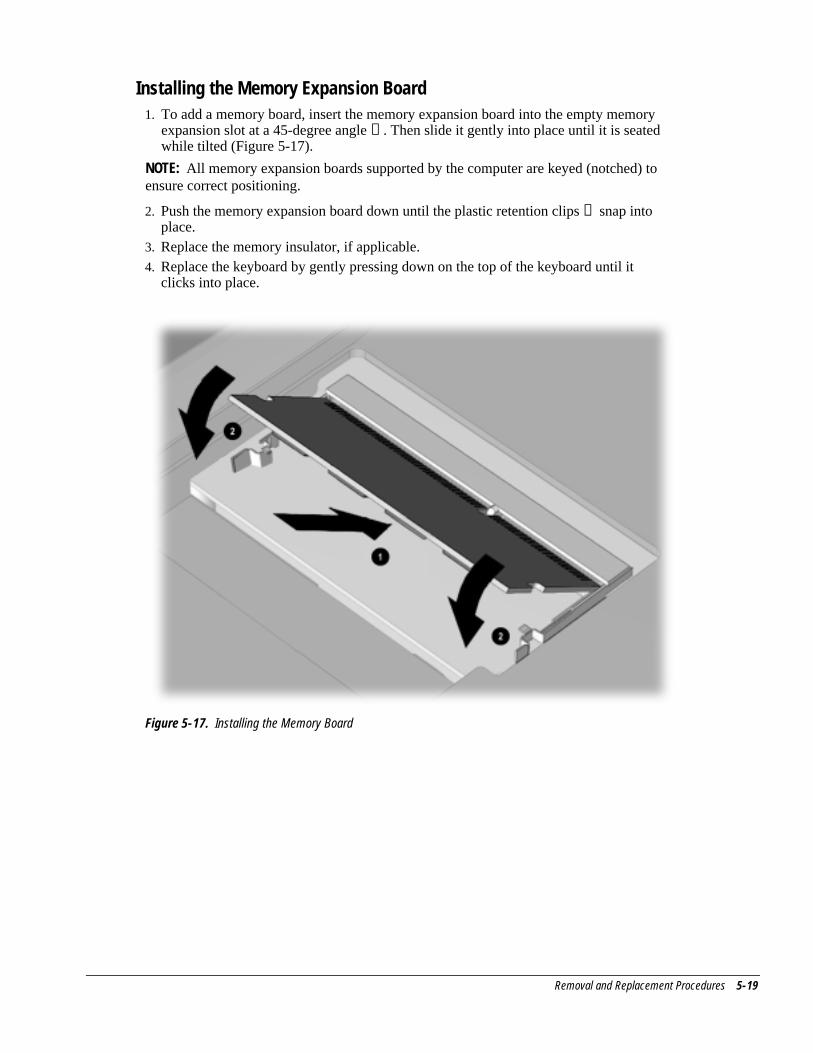
Removal and Replacement Procedures 5-19
Installing the Memory Expansion Board1. To add a memory board, insert the memory expansion board into the empty memory
expansion slot at a 45-degree angle ➊ . Then slide it gently into place until it is seatedwhile tilted (Figure 5-17).
NOTE: All memory expansion boards supported by the computer are keyed (notched) toensure correct positioning.
2. Push the memory expansion board down until the plastic retention clips ➋ snap intoplace.
3. Replace the memory insulator, if applicable.4. Replace the keyboard by gently pressing down on the top of the keyboard until it
clicks into place.
Figure 5-17. Installing the Memory Board
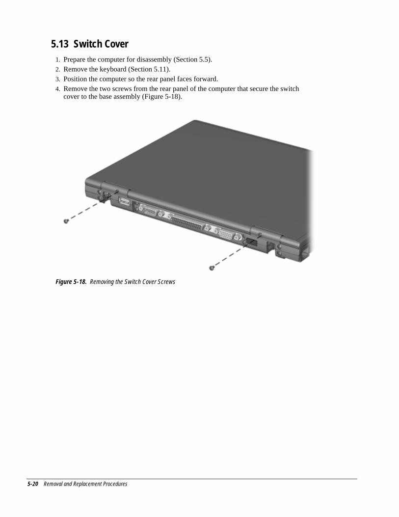
5-20 Removal and Replacement Procedures
5.13 Switch Cover1. Prepare the computer for disassembly (Section 5.5).2. Remove the keyboard (Section 5.11).3. Position the computer so the rear panel faces forward.4. Remove the two screws from the rear panel of the computer that secure the switch
cover to the base assembly (Figure 5-18).
Figure 5-18. Removing the Switch Cover Screws
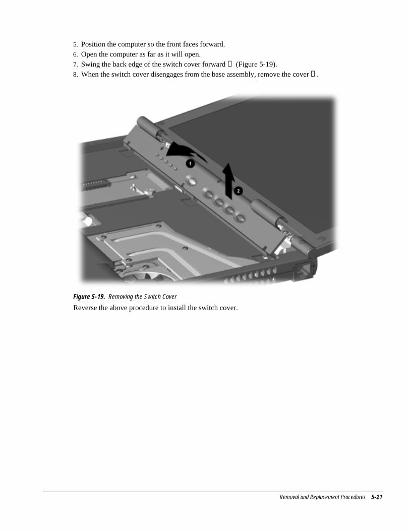
Removal and Replacement Procedures 5-21
5. Position the computer so the front faces forward.6. Open the computer as far as it will open.7. Swing the back edge of the switch cover forward ➊ (Figure 5-19).8. When the switch cover disengages from the base assembly, remove the cover ➋ .
Figure 5-19. Removing the Switch Cover
Reverse the above procedure to install the switch cover.
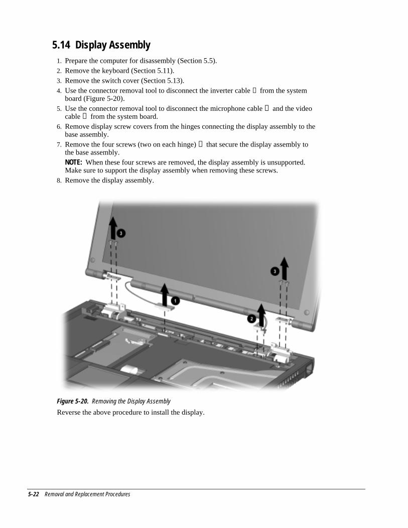
5-22 Removal and Replacement Procedures
5.14 Display Assembly1. Prepare the computer for disassembly (Section 5.5).2. Remove the keyboard (Section 5.11).3. Remove the switch cover (Section 5.13).4. Use the connector removal tool to disconnect the inverter cable ➊ from the system
board (Figure 5-20).5. Use the connector removal tool to disconnect the microphone cable ➋ and the video
cable ➋ from the system board.6. Remove display screw covers from the hinges connecting the display assembly to the
base assembly.7. Remove the four screws (two on each hinge) ➌ that secure the display assembly to
the base assembly. NOTE: When these four screws are removed, the display assembly is unsupported.
Make sure to support the display assembly when removing these screws.8. Remove the display assembly.
Figure 5-20. Removing the Display Assembly
Reverse the above procedure to install the display.
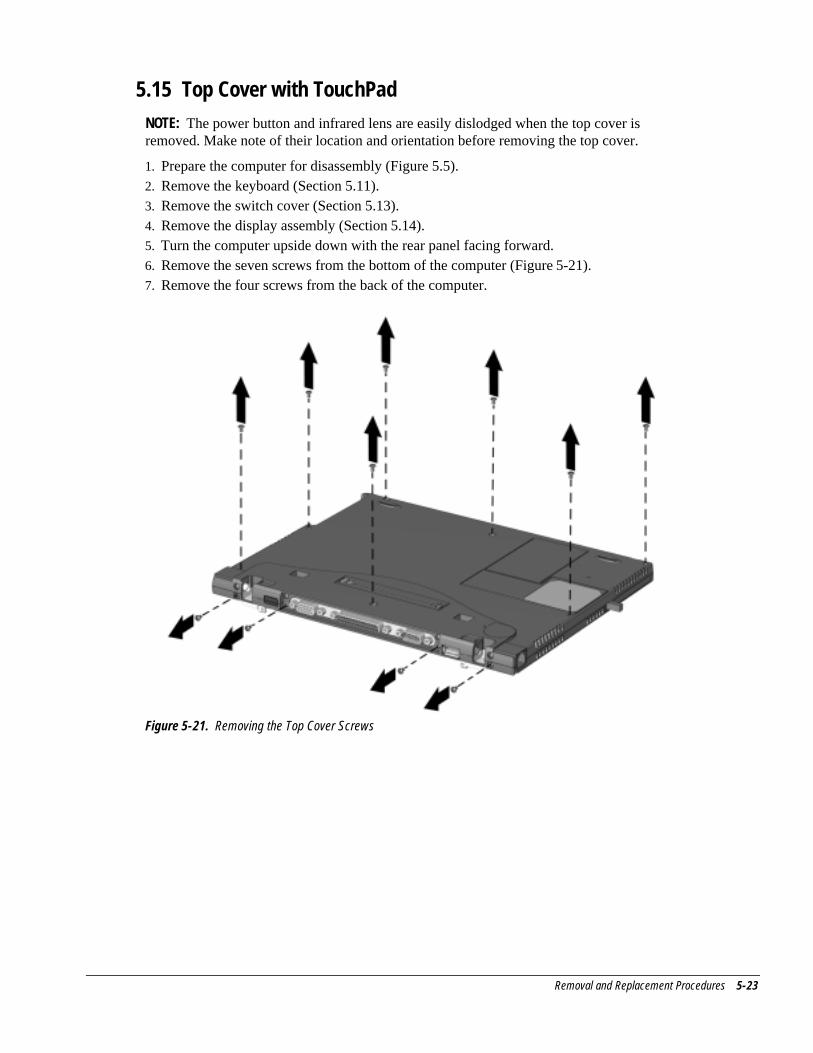
Removal and Replacement Procedures 5-23
5.15 Top Cover with TouchPadNOTE: The power button and infrared lens are easily dislodged when the top cover isremoved. Make note of their location and orientation before removing the top cover.
1. Prepare the computer for disassembly (Figure 5.5).2. Remove the keyboard (Section 5.11).3. Remove the switch cover (Section 5.13).4. Remove the display assembly (Section 5.14).5. Turn the computer upside down with the rear panel facing forward.6. Remove the seven screws from the bottom of the computer (Figure 5-21).7. Remove the four screws from the back of the computer.
Figure 5-21. Removing the Top Cover Screws
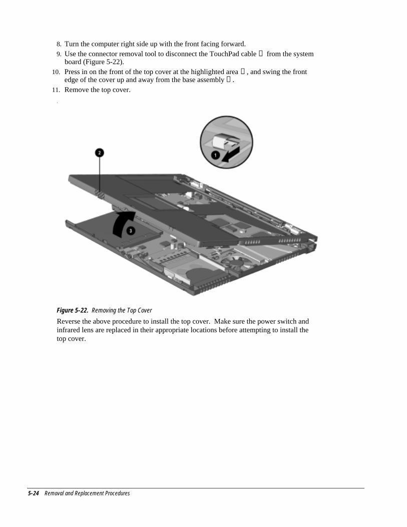
5-24 Removal and Replacement Procedures
8. Turn the computer right side up with the front facing forward.9. Use the connector removal tool to disconnect the TouchPad cable ➊ from the system
board (Figure 5-22).10. Press in on the front of the top cover at the highlighted area ➋ , and swing the front
edge of the cover up and away from the base assembly ➌ .11. Remove the top cover.
.
Figure 5-22. Removing the Top Cover
Reverse the above procedure to install the top cover. Make sure the power switch andinfrared lens are replaced in their appropriate locations before attempting to install thetop cover.
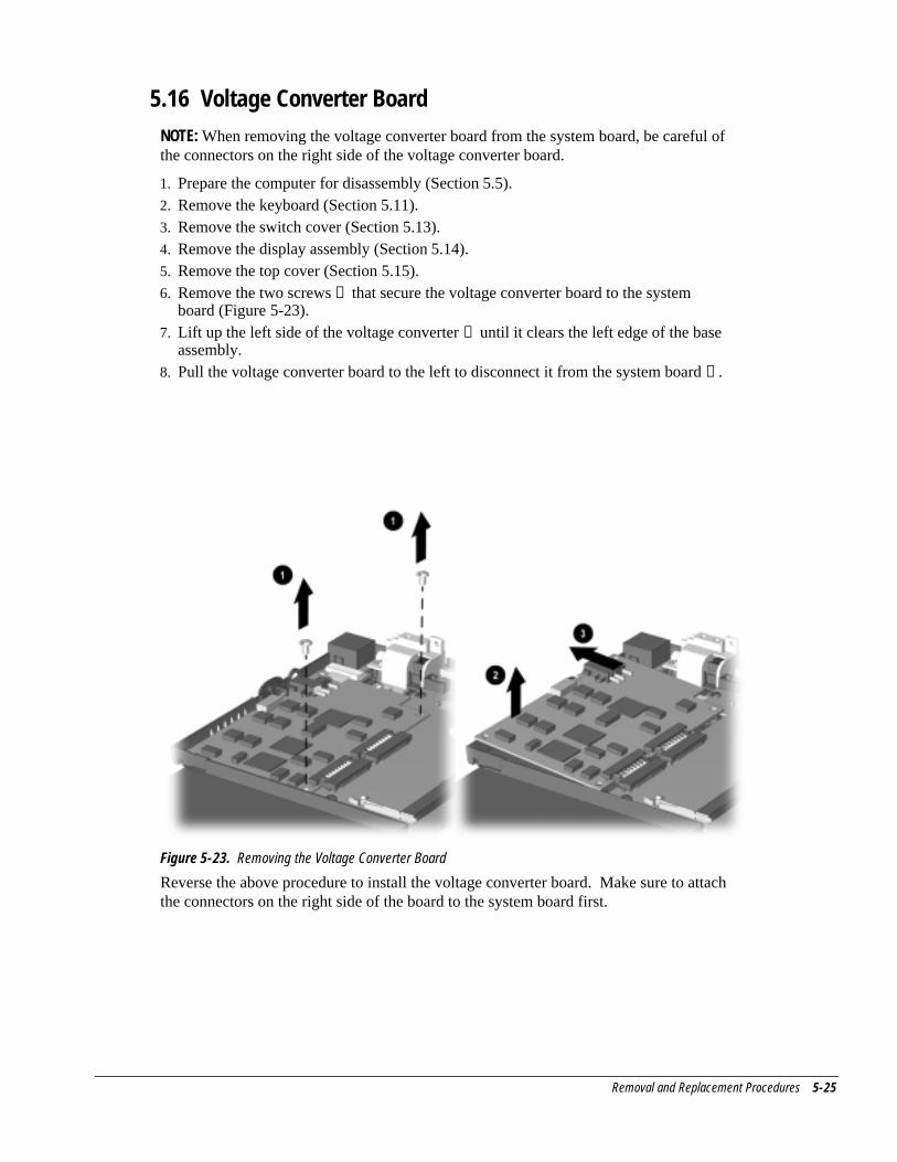
Removal and Replacement Procedures 5-25
5.16 Voltage Converter BoardNOTE: When removing the voltage converter board from the system board, be careful ofthe connectors on the right side of the voltage converter board.
1. Prepare the computer for disassembly (Section 5.5).2. Remove the keyboard (Section 5.11).3. Remove the switch cover (Section 5.13).4. Remove the display assembly (Section 5.14).5. Remove the top cover (Section 5.15).6. Remove the two screws ➊ that secure the voltage converter board to the system
board (Figure 5-23).7. Lift up the left side of the voltage converter ➋ until it clears the left edge of the base
assembly.8. Pull the voltage converter board to the left to disconnect it from the system board ➌ .
Figure 5-23. Removing the Voltage Converter Board
Reverse the above procedure to install the voltage converter board. Make sure to attachthe connectors on the right side of the board to the system board first.
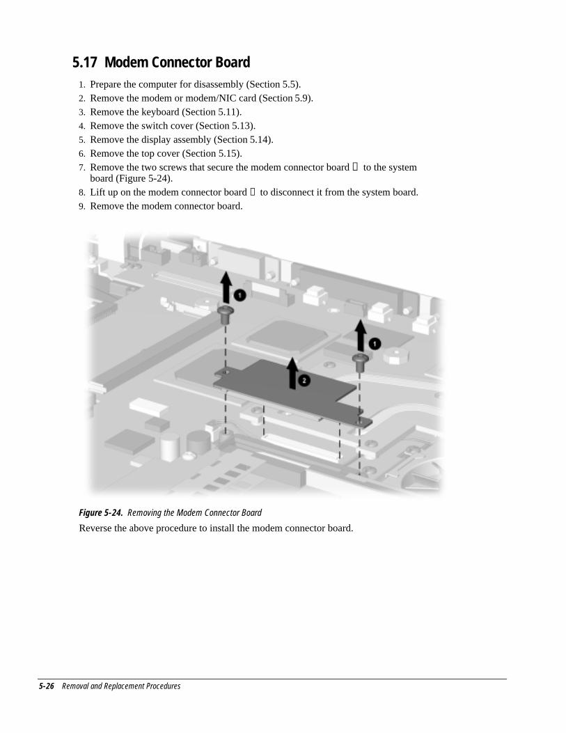
5-26 Removal and Replacement Procedures
5.17 Modem Connector Board1. Prepare the computer for disassembly (Section 5.5).2. Remove the modem or modem/NIC card (Section 5.9).3. Remove the keyboard (Section 5.11).4. Remove the switch cover (Section 5.13).5. Remove the display assembly (Section 5.14).6. Remove the top cover (Section 5.15).7. Remove the two screws that secure the modem connector board ➊ to the system
board (Figure 5-24).8. Lift up on the modem connector board ➋ to disconnect it from the system board.9. Remove the modem connector board.
Figure 5-24. Removing the Modem Connector Board
Reverse the above procedure to install the modem connector board.
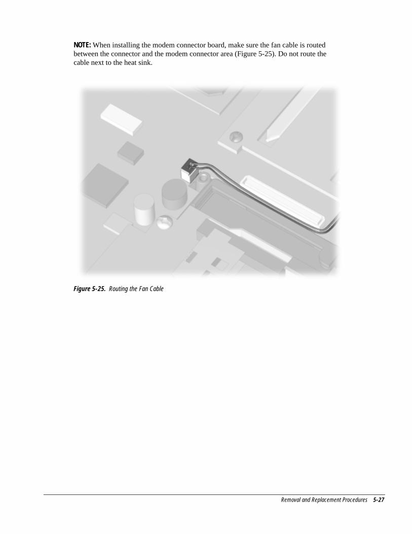
Removal and Replacement Procedures 5-27
NOTE: When installing the modem connector board, make sure the fan cable is routedbetween the connector and the modem connector area (Figure 5-25). Do not route thecable next to the heat sink.
Figure 5-25. Routing the Fan Cable
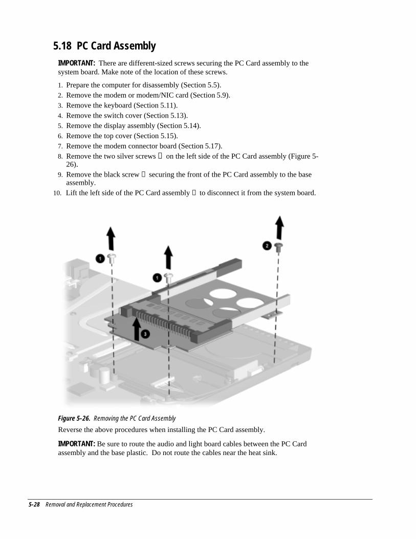
5-28 Removal and Replacement Procedures
5.18 PC Card AssemblyIMPORTANT: There are different-sized screws securing the PC Card assembly to thesystem board. Make note of the location of these screws.
1. Prepare the computer for disassembly (Section 5.5).2. Remove the modem or modem/NIC card (Section 5.9).3. Remove the keyboard (Section 5.11).4. Remove the switch cover (Section 5.13).5. Remove the display assembly (Section 5.14).6. Remove the top cover (Section 5.15).7. Remove the modem connector board (Section 5.17).8. Remove the two silver screws ➊ on the left side of the PC Card assembly (Figure 5-
26).9. Remove the black screw ➋ securing the front of the PC Card assembly to the base
assembly.10. Lift the left side of the PC Card assembly ➌ to disconnect it from the system board.
Figure 5-26. Removing the PC Card Assembly
Reverse the above procedures when installing the PC Card assembly.
IMPORTANT: Be sure to route the audio and light board cables between the PC Cardassembly and the base plastic. Do not route the cables near the heat sink.
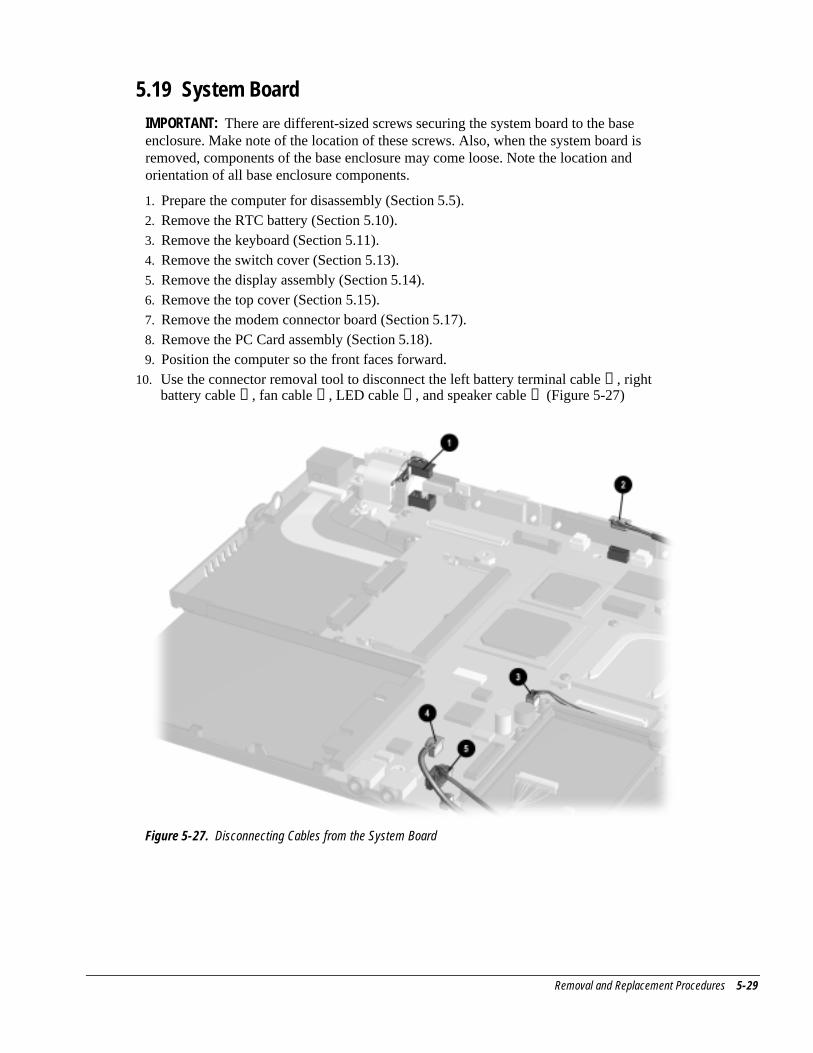
Removal and Replacement Procedures 5-29
5.19 System BoardIMPORTANT: There are different-sized screws securing the system board to the baseenclosure. Make note of the location of these screws. Also, when the system board isremoved, components of the base enclosure may come loose. Note the location andorientation of all base enclosure components.
1. Prepare the computer for disassembly (Section 5.5).2. Remove the RTC battery (Section 5.10).3. Remove the keyboard (Section 5.11).4. Remove the switch cover (Section 5.13).5. Remove the display assembly (Section 5.14).6. Remove the top cover (Section 5.15).7. Remove the modem connector board (Section 5.17).8. Remove the PC Card assembly (Section 5.18).9. Position the computer so the front faces forward.
10. Use the connector removal tool to disconnect the left battery terminal cable ➊ , rightbattery cable ➋ , fan cable ➌ , LED cable ➍ , and speaker cable ➎ (Figure 5-27)
Figure 5-27. Disconnecting Cables from the System Board
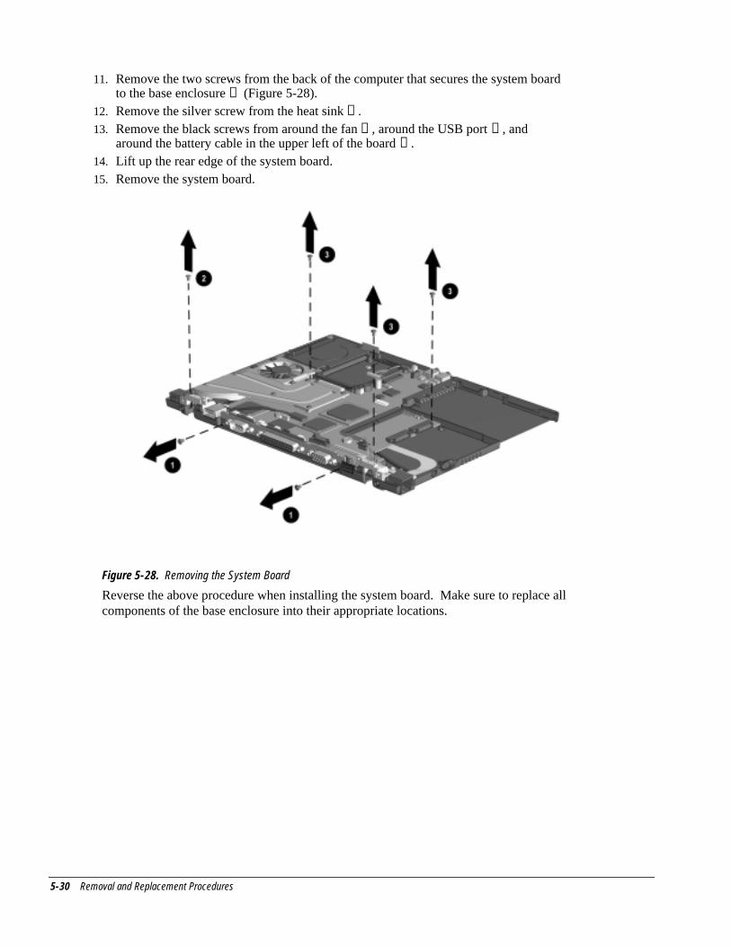
5-30 Removal and Replacement Procedures
11. Remove the two screws from the back of the computer that secures the system boardto the base enclosure ➊ (Figure 5-28).
12. Remove the silver screw from the heat sink ➋ .13. Remove the black screws from around the fan ➌ , around the USB port ➌ , and
around the battery cable in the upper left of the board ➌ .14. Lift up the rear edge of the system board.15. Remove the system board.
Figure 5-28. Removing the System Board
Reverse the above procedure when installing the system board. Make sure to replace allcomponents of the base enclosure into their appropriate locations.
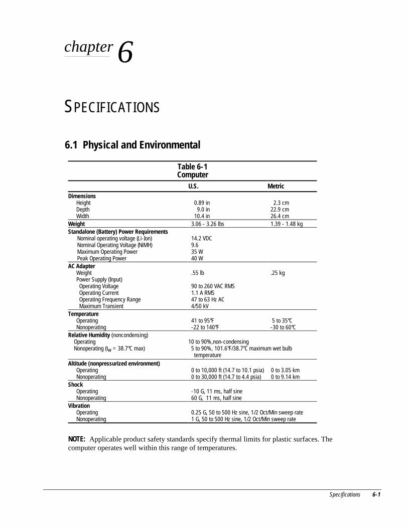
Specifications 6-1
chapter 6
SPECIFICATIONS
6.1 Physical and Environmental
Table 6-1Computer
U.S. MetricDimensions
HeightDepthWidth
0.89 in 9.0 in 10.4 in
2.3 cm22.9 cm26.4 cm
Weight 3.06 - 3.26 lbs 1.39 - 1.48 kgStandalone (Battery) Power Requirements
Nominal operating voltage (Li-Ion)Nominal Operating Voltage (NiMH)Maximum Operating PowerPeak Operating Power
14.2 VDC9.635 W40 W
AC AdapterWeightPower Supply (Input) Operating Voltage Operating Current Operating Frequency Range Maximum Transient
.55 lb
90 to 260 VAC RMS1.1 A RMS47 to 63 Hz AC4/50 kV
.25 kg
TemperatureOperatingNonoperating
41 to 95°F-22 to 140°F
5 to 35°C-30 to 60°C
Relative Humidity (noncondensing)OperatingNonoperating (tw = 38.7°C max)
10 to 90%,non-condensing 5 to 90%, 101.6°F/38.7°C maximum wet bulb
temperatureAltitude (nonpressurized environment)
OperatingNonoperating
0 to 10,000 ft (14.7 to 10.1 psia)0 to 30,000 ft (14.7 to 4.4 psia)
0 to 3.05 km0 to 9.14 km
ShockOperatingNonoperating
-10 G, 11 ms, half sine60 G, 11 ms, half sine
VibrationOperatingNonoperating
0.25 G, 50 to 500 Hz sine, 1/2 Oct/Min sweep rate1 G, 50 to 500 Hz sine, 1/2 Oct/Min sweep rate
NOTE: Applicable product safety standards specify thermal limits for plastic surfaces. Thecomputer operates well within this range of temperatures.
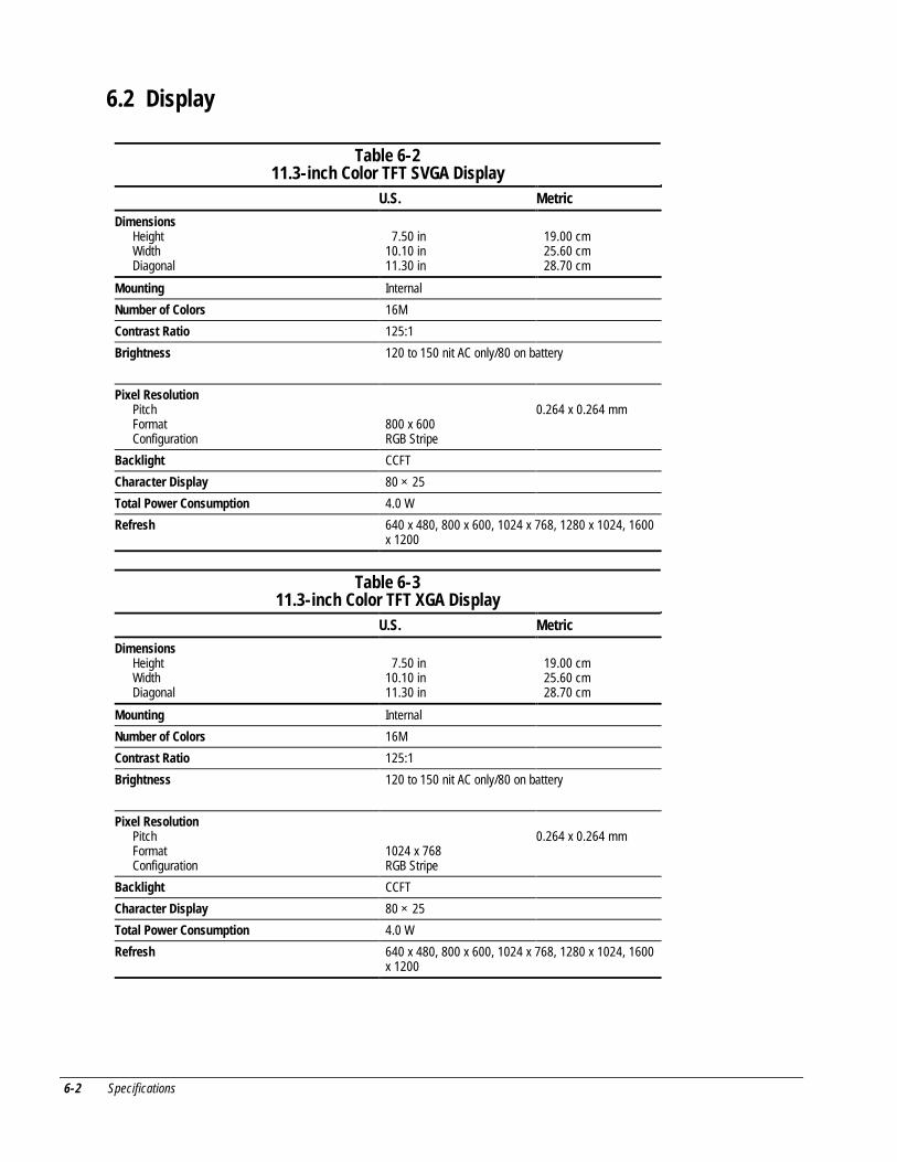
6-2 Specifications
6.2 Display
Table 6-211.3-inch Color TFT SVGA Display
U.S. Metric
DimensionsHeightWidthDiagonal
7.50 in10.10 in11.30 in
19.00 cm25.60 cm28.70 cm
Mounting Internal
Number of Colors 16M
Contrast Ratio 125:1
Brightness 120 to 150 nit AC only/80 on battery
Pixel ResolutionPitchFormatConfiguration
800 x 600RGB Stripe
0.264 x 0.264 mm
Backlight CCFT
Character Display 80 × 25
Total Power Consumption 4.0 W
Refresh 640 x 480, 800 x 600, 1024 x 768, 1280 x 1024, 1600x 1200
Table 6-311.3-inch Color TFT XGA Display
U.S. Metric
DimensionsHeightWidthDiagonal
7.50 in10.10 in11.30 in
19.00 cm25.60 cm28.70 cm
Mounting Internal
Number of Colors 16M
Contrast Ratio 125:1
Brightness 120 to 150 nit AC only/80 on battery
Pixel ResolutionPitchFormatConfiguration
1024 x 768RGB Stripe
0.264 x 0.264 mm
Backlight CCFT
Character Display 80 × 25
Total Power Consumption 4.0 W
Refresh 640 x 480, 800 x 600, 1024 x 768, 1280 x 1024, 1600x 1200
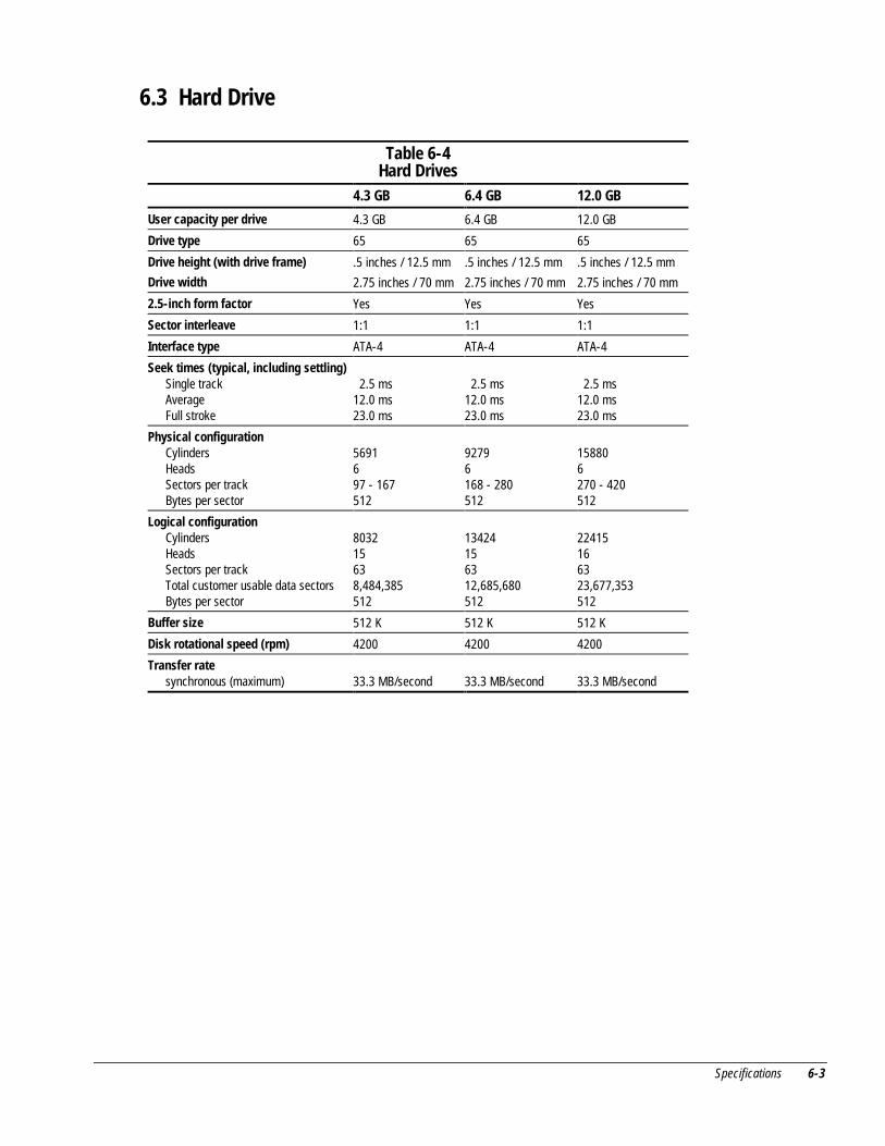
Specifications 6-3
6.3 Hard Drive
Table 6-4Hard Drives
4.3 GB 6.4 GB 12.0 GB
User capacity per drive 4.3 GB 6.4 GB 12.0 GB
Drive type 65 65 65
Drive height (with drive frame)
Drive width
.5 inches / 12.5 mm
2.75 inches / 70 mm
.5 inches / 12.5 mm
2.75 inches / 70 mm
.5 inches / 12.5 mm
2.75 inches / 70 mm
2.5-inch form factor Yes Yes Yes
Sector interleave 1:1 1:1 1:1
Interface type ATA-4 ATA-4 ATA-4
Seek times (typical, including settling)Single trackAverageFull stroke
2.5 ms12.0 ms23.0 ms
2.5 ms12.0 ms23.0 ms
2.5 ms12.0 ms23.0 ms
Physical configurationCylindersHeadsSectors per trackBytes per sector
5691697 - 167512
92796168 - 280512
158806270 - 420512
Logical configurationCylindersHeadsSectors per trackTotal customer usable data sectorsBytes per sector
803215638,484,385512
13424156312,685,680512
22415166323,677,353512
Buffer size 512 K 512 K 512 K
Disk rotational speed (rpm) 4200 4200 4200
Transfer ratesynchronous (maximum) 33.3 MB/second 33.3 MB/second 33.3 MB/second
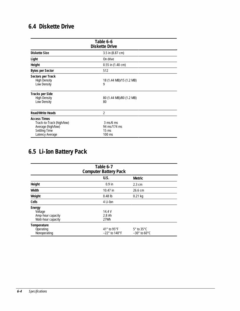
6-4 Specifications
6.4 Diskette Drive
Table 6-6Diskette Drive
Diskette Size 3.5 in (8.87 cm)
Light On drive
Height 0.55 in (1.40 cm)
Bytes per Sector 512
Sectors per TrackHigh DensityLow Density
18 (1.44 MB)/15 (1.2 MB)9
Tracks per SideHigh DensityLow Density
80 (1.44 MB)/80 (1.2 MB)80
Read/Write Heads 2
Access TimesTrack-to-Track (high/low)Average (high/low)Settling TimeLatency Average
3 ms/6 ms94 ms/174 ms15 ms100 ms
6.5 Li-Ion Battery Pack
Table 6-7Computer Battery Pack
U.S. Metric
Height 0.9 in 2.3 cm
Width 10.47 in 26.6 cm
Weight 0.48 lb 0.21 kg
Cells 4 Li-Ion
EnergyVoltageAmp-hour capacityWatt-hour capacity
14.4 V2.8 Ah27Wh
TemperatureOperatingNonoperating
41° to 95° F– 22° to 140° F
5° to 35° C– 30° to 60° C
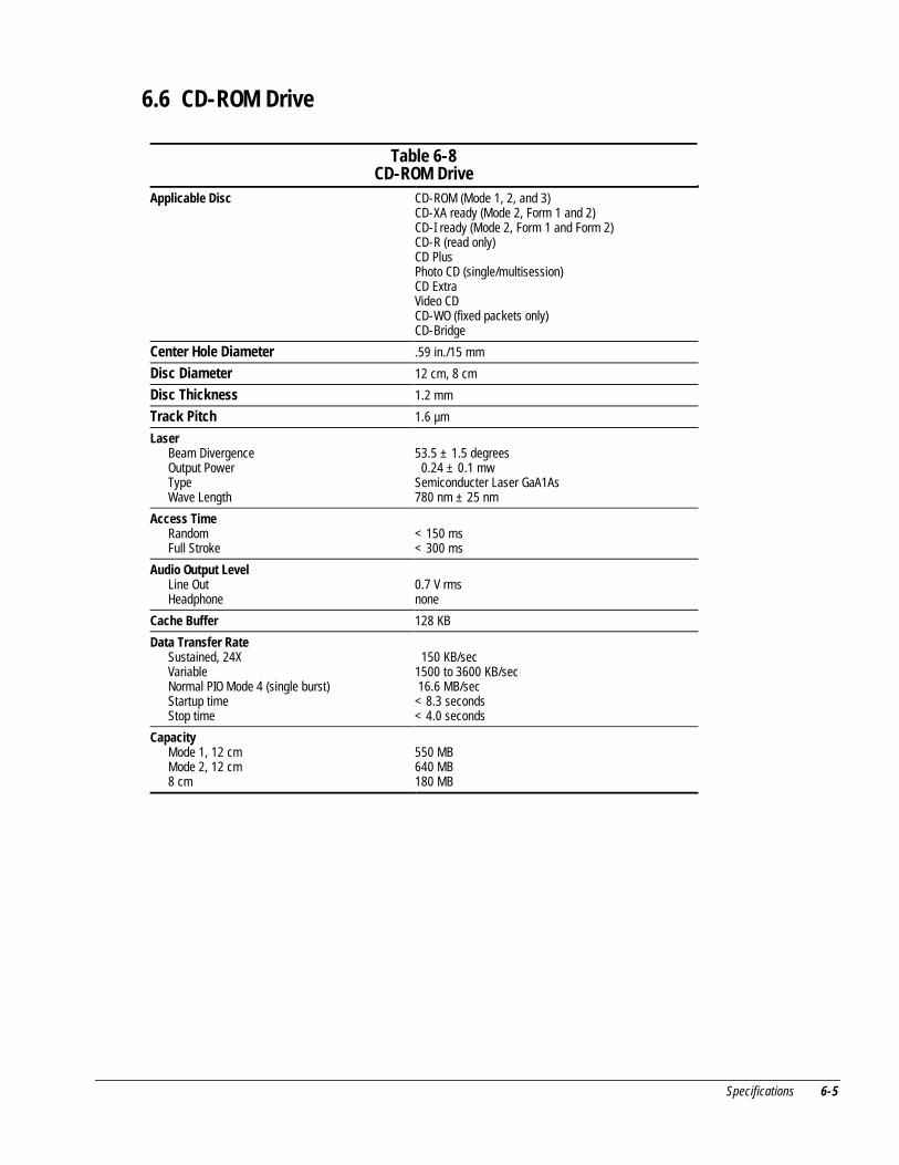
Specifications 6-5
6.6 CD-ROM Drive
Table 6-8CD-ROM Drive
Applicable Disc CD-ROM (Mode 1, 2, and 3)CD-XA ready (Mode 2, Form 1 and 2)CD-I ready (Mode 2, Form 1 and Form 2)CD-R (read only)CD PlusPhoto CD (single/multisession)CD ExtraVideo CDCD-WO (fixed packets only)CD-Bridge
Center Hole Diameter .59 in./15 mm
Disc Diameter 12 cm, 8 cm
Disc Thickness 1.2 mm
Track Pitch 1.6 µm
LaserBeam DivergenceOutput PowerTypeWave Length
53.5 ± 1.5 degrees 0.24 ± 0.1 mwSemiconducter Laser GaA1As780 nm ± 25 nm
Access TimeRandomFull Stroke
< 150 ms< 300 ms
Audio Output LevelLine OutHeadphone
0.7 V rmsnone
Cache Buffer 128 KB
Data Transfer RateSustained, 24XVariableNormal PIO Mode 4 (single burst)Startup timeStop time
150 KB/sec1500 to 3600 KB/sec 16.6 MB/sec< 8.3 seconds< 4.0 seconds
CapacityMode 1, 12 cmMode 2, 12 cm8 cm
550 MB640 MB180 MB
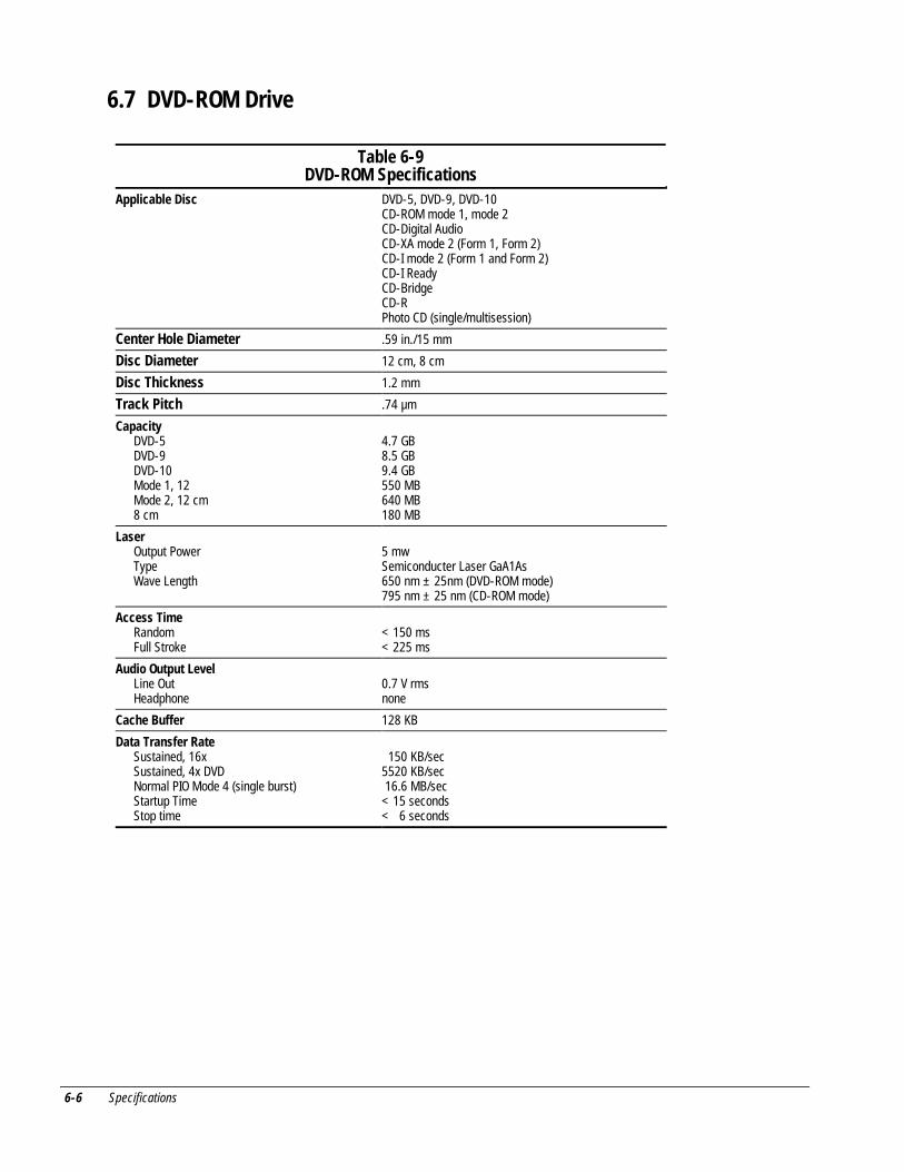
6-6 Specifications
6.7 DVD-ROM Drive
Table 6-9DVD-ROM Specifications
Applicable Disc DVD-5, DVD-9, DVD-10CD-ROM mode 1, mode 2CD-Digital AudioCD-XA mode 2 (Form 1, Form 2)CD-I mode 2 (Form 1 and Form 2)CD-I ReadyCD-BridgeCD-RPhoto CD (single/multisession)
Center Hole Diameter .59 in./15 mm
Disc Diameter 12 cm, 8 cm
Disc Thickness 1.2 mm
Track Pitch .74 µm
CapacityDVD-5DVD-9DVD-10Mode 1, 12Mode 2, 12 cm8 cm
4.7 GB8.5 GB9.4 GB550 MB640 MB180 MB
LaserOutput PowerTypeWave Length
5 mwSemiconducter Laser GaA1As650 nm ± 25nm (DVD-ROM mode)795 nm ± 25 nm (CD-ROM mode)
Access TimeRandomFull Stroke
< 150 ms< 225 ms
Audio Output LevelLine OutHeadphone
0.7 V rmsnone
Cache Buffer 128 KB
Data Transfer RateSustained, 16xSustained, 4x DVDNormal PIO Mode 4 (single burst)Startup TimeStop time
150 KB/sec5520 KB/sec 16.6 MB/sec< 15 seconds< 6 seconds
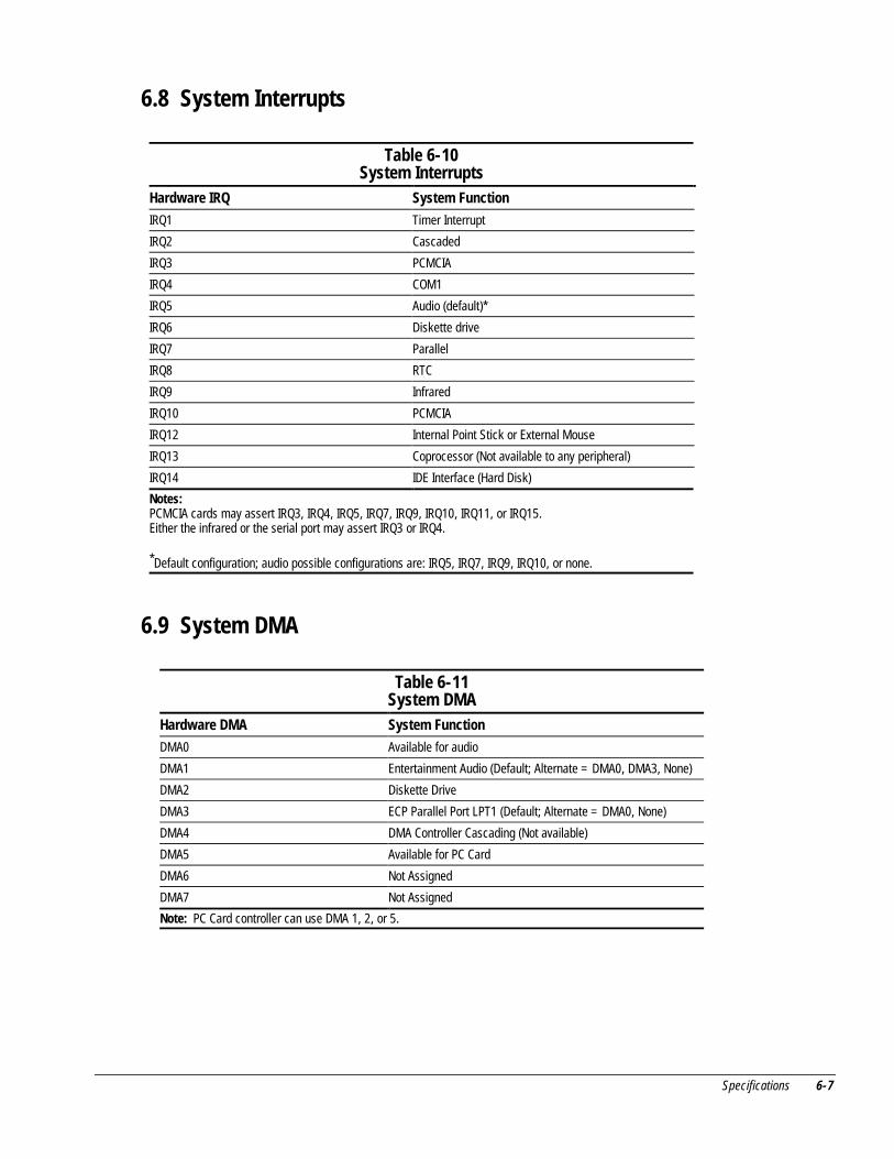
Specifications 6-7
6.8 System Interrupts
Table 6-10System Interrupts
Hardware IRQ System Function
IRQ1 Timer Interrupt
IRQ2 Cascaded
IRQ3 PCMCIA
IRQ4 COM1
IRQ5 Audio (default)*
IRQ6 Diskette drive
IRQ7 Parallel
IRQ8 RTC
IRQ9 Infrared
IRQ10 PCMCIA
IRQ12 Internal Point Stick or External Mouse
IRQ13 Coprocessor (Not available to any peripheral)
IRQ14 IDE Interface (Hard Disk)
Notes:PCMCIA cards may assert IRQ3, IRQ4, IRQ5, IRQ7, IRQ9, IRQ10, IRQ11, or IRQ15.Either the infrared or the serial port may assert IRQ3 or IRQ4.
*Default configuration; audio possible configurations are: IRQ5, IRQ7, IRQ9, IRQ10, or none.
6.9 System DMA
Table 6-11System DMA
Hardware DMA System Function
DMA0 Available for audio
DMA1 Entertainment Audio (Default; Alternate = DMA0, DMA3, None)
DMA2 Diskette Drive
DMA3 ECP Parallel Port LPT1 (Default; Alternate = DMA0, None)
DMA4 DMA Controller Cascading (Not available)
DMA5 Available for PC Card
DMA6 Not Assigned
DMA7 Not Assigned
Note: PC Card controller can use DMA 1, 2, or 5.
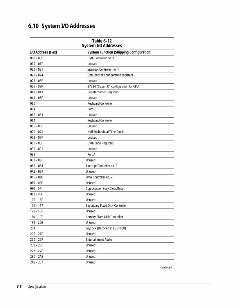
6-8 Specifications
6.10 System I/O Addresses
Table 6-12System I/O Addresses
I/O Address (Hex) System Function (Shipping Configuration)
000 - 00F DMA Controller no. 1
010 - 01F Unused
020 - 021 Interrupt Controller no. 1
022 - 024 Opti Chipset Configuration registers
025 - 03F Unused
02E - 02F 87334 "Super IO" configuration for CPU
040 - 043 Counter/Timer Registers
044 - 05F Unused
060 Keyboard Controller
061 Port B
062 - 063 Unused
064 Keyboard Controller
065 - 06F Unused
070 - 071 NMI Enable/Real Time Clock
072 - 07F Unused
080 - 08F DMA Page Registers
090 - 091 Unused
092 Port A
093 - 09F Unused
0A0 - 0A1 Interrupt Controller no. 2
0A2 - 0BF Unused
0C0 - 0DF DMA Controller no. 2
0E0 - 0EF Unused
0F0 - 0F1 Coprocessor Busy Clear/Reset
0F2 - 0FF Unused
100 - 16F Unused
170 - 177 Secondary Fixed Disk Controller
178 - 1EF Unused
1F0 - 1F7 Primary Fixed Disk Controller
1F8 - 200 Unused
201 Joystick (Decoded in ESS1688)
202 - 21F Unused
220 - 22F Entertainment Audio
230 - 26D Unused
278 - 27F Unused
280 - 2AB Unused
2A8 - 2E7 UnusedContinued
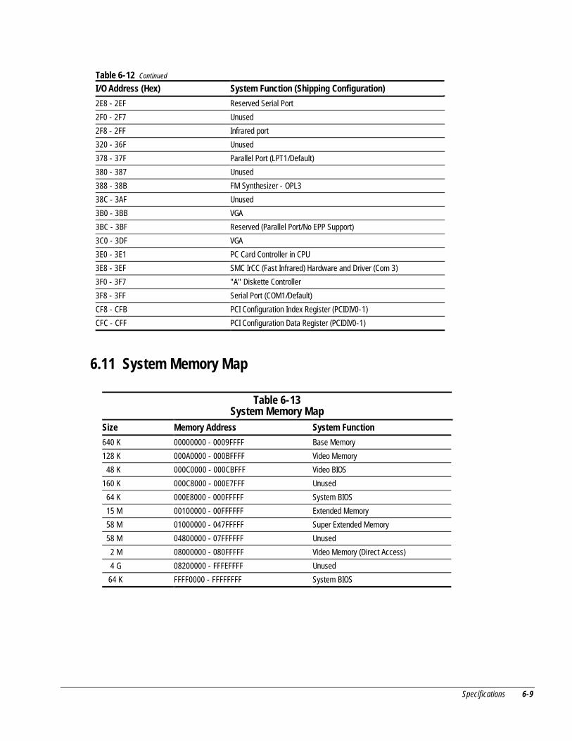
Specifications 6-9
Table 6-12 Continued
I/O Address (Hex) System Function (Shipping Configuration)
2E8 - 2EF Reserved Serial Port
2F0 - 2F7 Unused
2F8 - 2FF Infrared port
320 - 36F Unused
378 - 37F Parallel Port (LPT1/Default)
380 - 387 Unused
388 - 38B FM Synthesizer - OPL3
38C - 3AF Unused
3B0 - 3BB VGA
3BC - 3BF Reserved (Parallel Port/No EPP Support)
3C0 - 3DF VGA
3E0 - 3E1 PC Card Controller in CPU
3E8 - 3EF SMC IrCC (Fast Infrared) Hardware and Driver (Com 3)
3F0 - 3F7 "A" Diskette Controller
3F8 - 3FF Serial Port (COM1/Default)
CF8 - CFB PCI Configuration Index Register (PCIDIV0-1)
CFC - CFF PCI Configuration Data Register (PCIDIV0-1)
6.11 System Memory Map
Table 6-13System Memory Map
Size Memory Address System Function
640 K 00000000 - 0009FFFF Base Memory
128 K 000A0000 - 000BFFFF Video Memory
48 K 000C0000 - 000CBFFF Video BIOS
160 K 000C8000 - 000E7FFF Unused
64 K 000E8000 - 000FFFFF System BIOS
15 M 00100000 - 00FFFFFF Extended Memory
58 M 01000000 - 047FFFFF Super Extended Memory
58 M 04800000 - 07FFFFFF Unused
2 M 08000000 - 080FFFFF Video Memory (Direct Access)
4 G 08200000 - FFFEFFFF Unused
64 K FFFF0000 - FFFFFFFF System BIOS
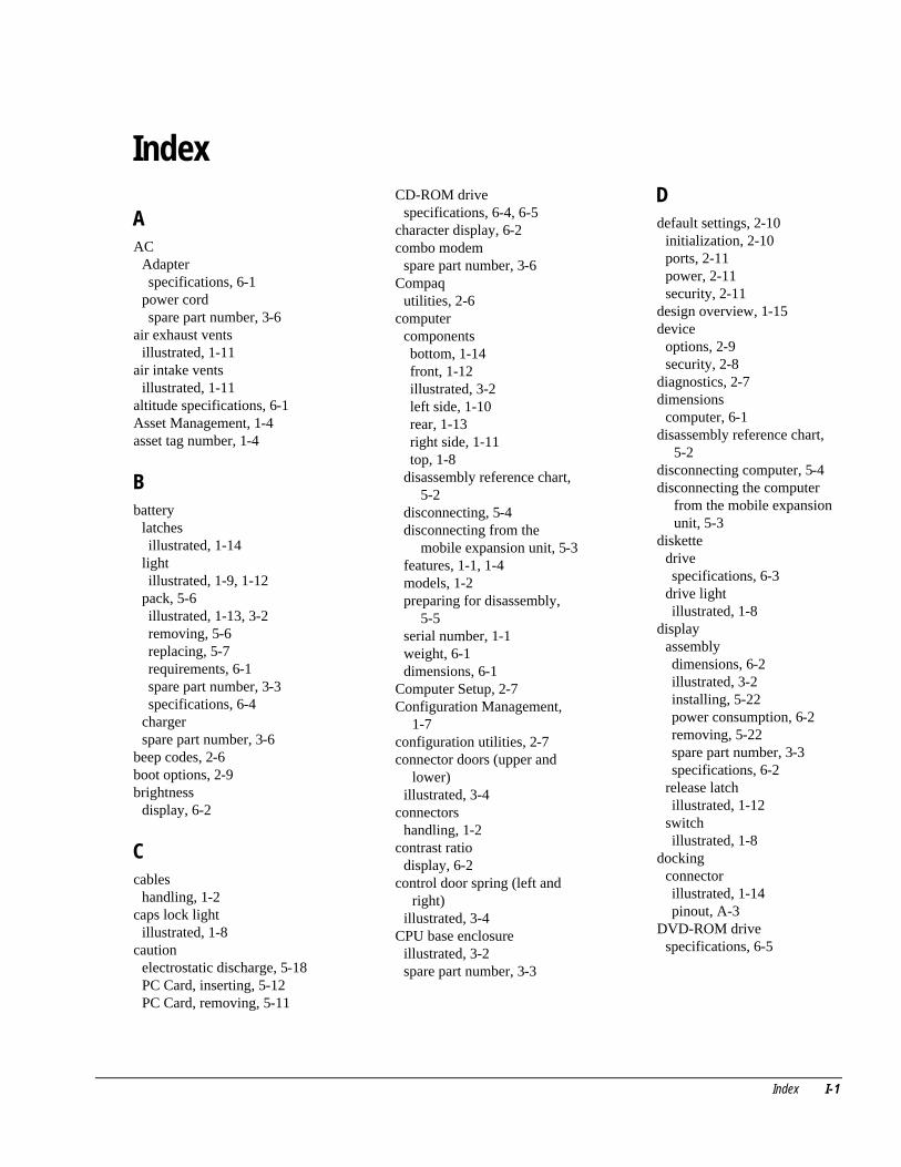
Index I-1
Index
AAC
Adapterspecifications, 6-1
power cordspare part number, 3-6
air exhaust ventsillustrated, 1-11
air intake ventsillustrated, 1-11
altitude specifications, 6-1Asset Management, 1-4asset tag number, 1-4
Bbattery
latchesillustrated, 1-14
lightillustrated, 1-9, 1-12
pack, 5-6illustrated, 1-13, 3-2removing, 5-6replacing, 5-7requirements, 6-1spare part number, 3-3specifications, 6-4
chargerspare part number, 3-6
beep codes, 2-6boot options, 2-9brightness
display, 6-2
Ccables
handling, 1-2caps lock light
illustrated, 1-8caution
electrostatic discharge, 5-18PC Card, inserting, 5-12PC Card, removing, 5-11
CD-ROM drivespecifications, 6-4, 6-5
character display, 6-2combo modem
spare part number, 3-6Compaq
utilities, 2-6computer
componentsbottom, 1-14front, 1-12illustrated, 3-2left side, 1-10rear, 1-13right side, 1-11top, 1-8
disassembly reference chart,5-2
disconnecting, 5-4disconnecting from the
mobile expansion unit, 5-3features, 1-1, 1-4models, 1-2preparing for disassembly,
5-5serial number, 1-1weight, 6-1dimensions, 6-1
Computer Setup, 2-7Configuration Management,
1-7configuration utilities, 2-7connector doors (upper and
lower)illustrated, 3-4
connectorshandling, 1-2
contrast ratiodisplay, 6-2
control door spring (left andright)
illustrated, 3-4CPU base enclosure
illustrated, 3-2spare part number, 3-3
Ddefault settings, 2-10
initialization, 2-10ports, 2-11power, 2-11security, 2-11
design overview, 1-15device
options, 2-9security, 2-8
diagnostics, 2-7dimensions
computer, 6-1disassembly reference chart,
5-2disconnecting computer, 5-4disconnecting the computer
from the mobile expansionunit, 5-3
diskettedrivespecifications, 6-3
drive lightillustrated, 1-8
displayassemblydimensions, 6-2illustrated, 3-2installing, 5-22power consumption, 6-2removing, 5-22spare part number, 3-3specifications, 6-2
release latchillustrated, 1-12
switchillustrated, 1-8
dockingconnectorillustrated, 1-14pinout, A-3
DVD-ROM drivespecifications, 6-5
I-2 Index
Eelectrostatic
damagepreventing, 1-3
dischargetypical voltage levels, 1-6
energy saving, 1-7environmental
specifications, 1-1external diskette drive
illustrated, 3-5spare part number, 3-5
external diskette drive cableillustrated, 3-5spare part number, 3-5
external monitorconnectorillustrated, 1-13
Ffan
illustrated, 1-14fatal error
beep codes, 2-6messages, 2-5
Fault Management, 1-5alerts, 1-6
features, 1-1, 1-2computer, 1-2
Ggrounding
methods, 1-5
Hhard drive, 5-8
bayillustrated, 1-10
bezelillustrated, 1-14
illustrated, 3-2, 3-5inserting, 5-9lightillustrated, 1-8
removing, 5-8security screwillustrated, 1-14
spare part number, 3-3, 3-5specifications, 6-3
hardwareupdating, 2-12
headphonejackillustrated, 1-12pinout, A-2
hinge rubber capillustrated, 3-4
humidity specifications, 6-1
II/O addresses, 6-7Info Messenger, 2-12infrared
portillustrated, 1-13
initializationdefault settings, 2-10
Intelligent Manageability, 1-4Asset Management, 1-4Configuration Management,
1-7Fault Management, 1-5alerts, 1-6
Security Management, 1-6Web Agent, 1-4
internal microphoneillustrated, 1-8
inventory information, 1-5IR lens
illustrated, 3-4
Kkeyboard
connectorpinout, A-5
illustrated, 3-2installing, 5-17removing, 5-16spare part number, 3-3
Mmaintenance
updating system, 2-12Maintenance & Service Guide
spare part number, 3-6mass storage devices
illustrated, 3-5
memoryexpansion, 5-18board
illustrated, 3-2installing, 5-19removing, 5-18spare part number, 3-3, 3-6
map, 6-9messages
fatal error, 2-5warning, 2-4
microphonejackillustrated, 1-12pinout, A-1
Microsoft logo keyillustrated, 1-9
mini PCI dummy cardillustrated, 3-4
Miscellaneous Plastic Kitcomponentsillustrated, 3-4
contents, 3-3, 3-4spare part number, 3-3, 3-4
Miscellaneous Screw Kitspare part number, 3-6
miscellaneous spare partnumbers, 3-6
mobile expansion unitfeatures, 1-2spare part number, 3-6
model table, 1-3models
computer, 1-3modem
compartmentillustrated, 1-14
connector boardillustrated, 3-2installing, 5-27removing, 5-26spare part number, 3-3
coverillustrated, 3-2, 3-4
illustrated, 3-2PC Cardspare part number, 3-6
modem/combo cardinstalling, 5-14, 5-26removing, 5-13

Index I-3
monitorconnectorpinout, A-6
mouseconnectorpinout, A-5
Nnum lock light
illustrated, 1-8
Ooperating system (installed),
1-2
Ppackaging
precautions, 1-3parallel
connectorillustrated, 1-13pinout, A-2
passwordclearing, 2-3
PC Card, 5-10assemblyillustrated, 3-2installing, 5-28removing, 5-28spare part number, 3-3
door, 5-12illustrated, 3-4spring
illustrated, 3-4eject button, 5-11guide rails, 5-12inserting, 5-12removing, 5-11slotillustrated, 1-11
stopping, 5-11physical
specifications, 1-1pick button
leftillustrated, 1-9
rightillustrated, 1-9
pixel resolutiondisplay, 6-2
plastic partshandling, 1-1
portsdefault settings, 2-11
POST(Power-On Self-Test), 2-3error messages, 2-4
powerbuttonillustrated, 1-10
connectorillustrated, 1-10
consumptiondisplay, 6-2
cord setcountry-specific
requirements, B-2general requirements, B-1requirements, 1-1, B-1
default settings, 2-11knobillustrated, 3-4
management, 1-7management levels, 1-7
power/suspend lightillustrated, 1-9, 1-12
Power-On Self-Test (POST),2-3
preparing for disassembly, 5-5processor board
illustrated, 3-2spare part number, 3-3
QQuickBoot, 2-9
Rreal time clock battery
coverillustrated, 3-4
illustrated, 1-14, 3-2, 3-4installing, 5-15removing, 5-15
refreshdisplay, 6-2
return kitspare part number, 3-6
RJ-11jackillustrated, 1-11pinout, A-1
RJ-45jackillustrated, 1-10
RTC batterycoverillustrated, 3-4
illustrated, 1-14, 3-4rubber feet
illustrated, 3-4
Ssaving energy, 1-7scroll lock light
illustrated, 1-8security
cable slotillustrated, 1-10
default settings, 2-11Security Management, 1-6serial
connectorillustrated, 1-13pinout, A-1
number, viiiillustrated, 1-14location, 3-1, 1-1
service considerations, 1-1setup
computer, 2-7shock specifications, 6-1software
Info Messenger, 2-12updating, 2-12
spare part numbersmajor components, 3-3mass storage devices, 3-5miscellaneous, 3-6
speakerillustrated, 1-14
specifications, 1-1battery pack, 6-4CD-ROM drive, 6-4, 6-5diskette drive, 6-3display, 6-2DMA, 6-7DVD-ROM drive, 6-5environmental, 1-1hard drive, 6-3I/O addresses, 6-7interrupts, 6-6memory map, 6-9physical, 1-1
I-4 Index
stereoline-injack
pinout, A-2speakerjack
illustrated, 1-12pinout, A-2
Suspend buttonillustrated, 1-8
switch coverillustrated, 3-2, 3-4installing, 5-21removing, 5-20
systemboard, 1-15installing, 5-30removing, 5-29
DMA, 6-7I/O address, 6-7IDs, 2-8interrupts, 6-6memory map, 6-9ROM updates, 2-12
Ttechnician notes, viitemperature specifications, 6-1tool
required for service, 1-1top cover
installing, 5-24removing, 5-23
Touchpadillustrated, 1-9spare part number, 3-3
transportingprecautions, 1-3
troubleshooting, 1-1checklist, 2-13preliminary steps, 2-2without diagnostics, 2-12
Uuniversal serial bus
connectorillustrated, 1-13
USBconnectorillustrated, 1-13
utilities, Compaq, 2-6
Vvents
illustrated, 1-10vibration specifications, 6-1video memory, 1-2voltage converter board
illustrated, 3-2installing, 5-25removing, 5-25spare part number, 3-3
Wwarning messages, 2-4Web Agent, 1-4weight
computer, 6-1Windows
application keyillustrated, 1-8
workstationprecautions, 1-4


![Compaq Armada E500 V300[1]](https://img.pdfslide.net/doc/110x75/577d1f4e1a28ab4e1e90511a/compaq-armada-e500-v3001.jpg)