Embed Size (px)
Citation preview
Revista Mexicana de Física 43, No. 6 (1997) 1010-1020
Comparative analysis of Lummer-Gehrcke andFabry-Perot interferometers
M.A. CERVANTES ANO E.V. KURMYSIlEVCentro de Investigación en Fi<ica. U"iversidad de SonoraApartado postal 5-088, 83190 HenrlOsillo. SO"., Mexico
Recibido el 11 de diciembre de 1996;aceptado el 18 de agosto de 199i
ABSTRACT. The multiple beam interferometrir schemes: LUIllIllC'r-Gehrcke(LG) and Fabry-Perot,(FP), are analyzed here on the oasis of a theoretical schcme which permits an easier way ofcomparison of the performances of ooth type of interferolllcters. \Ve fOllIld that LGI as well asthe side-illuminated FPI can provide an appr('ciable gain in the maximulll intensity of brightfringes, in fringe contrast ami in efficiency in comparison to that for the conventional FPI, evenwhen LGI has a finitc numoer of intcrfering rays. \Ve also dClllollstra.ted that for a given numberof reftections inside an interferometric cavity there a.lways cxists an optimal reftection coefficientwhich provides the maximuJU efficiency (the ratio bctween a maximum intensity in a bright fringeand the intensity of the incident beam) of an interferometric device.
RESUl\1EN. Los esquemas interferométricos de haces mt'Jltiples, Lutllmer-Gehrcke (LG) y Fabry-Perot (FP), son analizados sobre la va.se de un C:i<¡uclllatcórico quc facilita la comparación deldesempeño de estos dos dispositivos. Encont.ra.mos que ('1 LG al igual que un FP iluminadolateralmente pueden proporcionar apreciahles ganancia.s CH lo t.ocante a la intcnsidad pico de lasfranjas brillantes, en contraste de franja."iy eu eficicllcia en comparación con un FP convencional,aun cuando el LG emplea un mÍlllcro finito de haces. T.ulluil'n demostramos que dado un númerode reflexiones dentro de la placa, existe un coeficientc de reflecta.ncia. óptimo que rinde la mayoreficicncia; definida ésta como la razón entre la intcusi<ia<i pico y la intensidad incidente en laplaca.
PAes: Oi.60.Ly; Oi.65.Lb
1. INTRODUCTION
The interference of multiple beams of ligbt produced by refiections on dielectric planeparallel plates bas contributed significantly to the developlllent of bigh resolution spec-troscopy. The Fabry-Perot etalon [1,2] and the so called LUllllller Plate [3-5] precededthe devices known as the Fabry-Perot and the Lununer Gehrcke interferometers, bothdeveloped early in the XX century (see Refs. G and i). The FP is considered one of thelIlust COlIlpa.ct high rcsolutiull spectroscopcs which lta...."'i fOUlld a grca.t lIlany applicatioIlsin various scicntific ficlds. Bcsidcs, it cOlllprises the concepts of resonant cavity and thatof interference filter on which the laser is ba.,e,l. The LUlllluer plate has becOlne obso-lete due mainly to the greater fiexibility and less dilficulty in fabrication of the FP. Inaddition, the oevel0plllent of the thin lihu technology bas favoreo decisively the latter.Nevertheless, the iuterest ou this device is alive [8) particularly by its connection with
COMPARATIVE ANALYSIS OF L-G AND F-P INTF.RFEROMETERS 1011
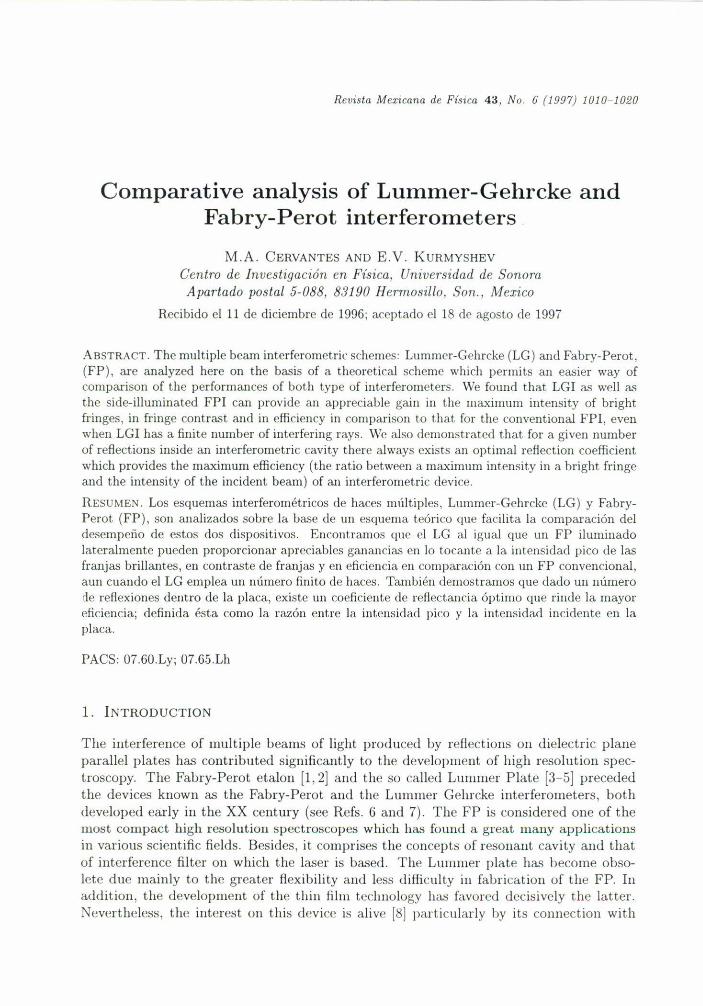
(a) (b) (e)FIGURE 1. Sehematie diagram of multiple beam interferenee in FP (a), and LG (b) "nd (e)illterferometers.
its potential utility in integrated optics systems [9J, Other aspects of the multiple beaminterference that have kept current interest can be found in Ref 10,
Figure I describes three ways to produce multiple beams in plane parallel plates, Thefirst one corresponds to an etalon whieh features two interference patterns: by transmis-sion alld by reficctioIl. Sincc the surfaces posscss high refieetances, the 6rst externalreflection, particularly strong, contri bu tes to form a pattern with fine dark fringes on abright background; the transmitted pattern, as is well kuown, is complementary of thereflection one if the losses are negligible. In both cases the maximum intensity is nearlyunitary. In Fig. Iba Lummer plate is used in the conventional fashion, i.e. light isintroduced by means of a Herschell wedge, eliminating so the first strong reflection andemploying most of the useful radiation to fonn two identical patterns of the transmissiontype, one aboye and one below the plateo It can be shown that in this situation, the peakintensity at the center of a bright fringe is always greater than unity. This is perhaps thereason why the LGI is recognized as being more useful on dealing with a weak sourceor in conditions of economy of light, than the FPI, where the peak intensity is e<¡ualto one at mosto Under normal use the LGI re<¡uires the internal reflections to occur atincidence anglcs ncar the critical angle, in arder to achieve reHectanccs sufficiclltly high,this reduces the number of interfering beams to a number between 10 to 30 typically.A small number of beams is undesirable for it produces fringe broadening and the ap-pearance of secondary maxima near the main peak which might be interpreted as weakadjacent lines. This does not oceur with a FPI for there the number of interfering beamsis practically illfillite and, COIlSCClICntly, the rclativc maxim<l disappcar.
Figure Ic depicts a Lunllner plate one of whose faces is fully reflecting. This canbe achieved, for example, by incidence with an angle grealer than the critical angle ofthis interface. The other interface is partly rcficcting becallse the incidence OCCllfS at anangle smaller than the corresponding critical angle of thal surfaee. In this fashion, mostof the luminous flux available is employed lo generale only one pattern aboye lhe partlyreflecting interface. The later method is more effieient than the cases (a) amI (b) for inthese cases the available flux is used to produce two redundant patterns with essentiallythe same anlount of informatioll.
In this manuscript a comparison is established between lhe well known FP and LGillterferomcters 011 the basis of a treatIllcnt COllllllOll to 1>oth <levices \\!hich pcnllits ancasier way of comparison of their intensity paramcters likc peak intcnsity, contra.."t alld.rcsolution.
1012 M.A. CERVANTES AND E.V. KURMYSHEV
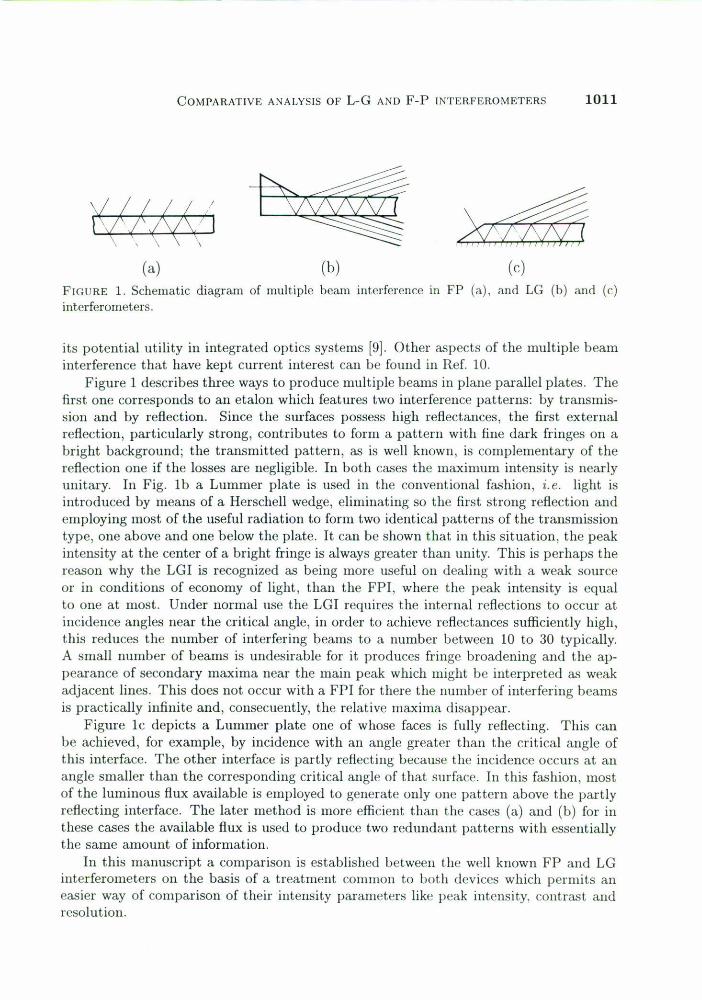
FIGURE2. Definingthe plate parameters.
2
(3)
2. GENERAL THEORETICAL TREATMENT
A theoretical treatment which is common to both LG and FP interferometres is con-sidered in this section. We suppose that a finite size solid plate of width 1 is positionedbetween two media. The plate has a refraction index n, while the refraction indices aboyeand below the plate are nI and n2 , correspondingly. We refer to Fig. 2 to define theterms employed. We suppose here that Aioe is the amplitnde of light in the incident beambefore entrance into the plate; Ao is the amplitude of light just before the first reflec-tion inside the interferometric device; TI is the amplitude reflection coeflicient inside adevice from the upper surface (n -t nI); tI is the corresponding amplitude transmissioncoeflicient; t; is the amplitude transmission coeflicient of the entrance surface; T2 is theamplitude reflection coeflicient inside a device from the lower surface (n -t n2).
Prom Fig. 2, the interfering beams in the outside plane of surface 1 have the followingamplitudes (the amplitudes of the successive rays reflected from the plate are):
Al = Ao T2tI; A2 = Ao T2hT2) tI exp (ió); A3 = Ao T2 (TI T2)2 tI exp (i2ó); ...
AN = Ao T2 (TI T2)N-l tI exp [i (N - 1) 15], (1)
The transmitted amplitudes are given by
A; = Ao t2; A~ = Ao (7.2 TI) t2 exp (ió); A; = Ao (T2 Tl)2 t2 exp (i2ó); ...
AN = Ao (T2 TI)N-l t2exp [i (N - 1) óJ. (2)
Here the phase difference between the two consecutive beams is given by
15 _ 277 ~ + q.- .\ cosO '
where.\ is the wave length of light, O is an incident angle inside a device, q. is the changeof phase at the reflection (if a change takes place).
The amplitude of a reflected resultant wave, which is a superposition of waves Eq. (1),is readily found to be equal to
A-~A -A 1-(rI7.2)Nexp(iNÓ)- L..J m - O r2 tI ---------,
m=1 1 - (TI 7.2) exp (ió)(4)
COMPARATIVE ANALYSIS OF L-G AND F-P INTERFEROMETERS 1013
where N is a number of interfering beallls. The intensity distribution, which correspondsto the wave Eq. (4), is as follows:
For a transmitted wave amplitude and intensity distributions we have from Eq.the following formulae:
'\l N'-~A' -A 1-(T\T2) exp(iN<5)
A - L.. m - O t2 ( ) ('<5)'I - TI T2 exp 1m=l
[1 - ("1 T2)"'f + 4 (TI T2)'" sin2 (N<5/2)[' = IA't2 = [Ot~~-----2--------
(1 - (TI T2)) + 4 (TI T2) sin2 (<5/2)
(5)
(2)
(6)
(7)
We note that, up to the moment, the scheme and lIletodology (even the final for-mulas) of calculation of lIlultiple beam interference were identical for both LG and FPinterferometers. The difference appears only in treating the transmission coefficient t;,of the entrance surface which depends on how an incident beam enters the device ineach particular case, and in the number of interfering beams N. The N is supposed tobe very large (N -+ 00) Cor FP devices, while N is supposed to be finite for LG ones,especially when one wants to exploit the total ¡nner reflection. In addition, a side illu-minated FPI can be considered as a LGI with entrance surface having the transmissioncoefficient t; = 1.
3. LUMMER-GEHRCKE BASED INTERFEROMETRY
First, we consider a LG device with total internal reflection (TIR) from the lower surfaceof the plate.1 Thus, the reflection coeflicient T2 = 1, and the nUlllber of reflections insidethe plate being N. The amplitude of light before the first reflection inside the plate isequal to Ao = Ainc t;, where Ainc is the amplitude of an incident beam, and t; is anamplitude transmission coefficient of the inclined surface, and we observe an interferencepattem in reflected light. (We take TI == T).
lThe idea oC increasing the reflectance of Dile surface oC the LGI is 110t new. As is knowD, during thefirst decades of the century, a number of researchers (11-14j, used metallic coatings Corthis airo. It wasthen recognized [15), that a substantial improvcment in peak intensity and contrast in the interferogramswas attainable under this modification. Such coatings in the best of cases produced appreciable lossesby aLsorptioll ano the reftectallces attained did 1101 exceeded 96%. SulJstantially improved multilayerdielectric coatings capable of rendering substantially greater reflection coefficient w¡th minimum losseshave never been used for tltis purpose, to our knowledge. Total internal refl.ection, on the other hand,guarantees ideal reflectance without any coating whatsoever.
1014 M.A. CERVANTESANDE.V. KURMYSIIEV
In arder to have TIR from the surfaee 2 we have to satisfy one of the fol!owingeonditions: (1) n > n\ > n2 (this is the most realistic condition for LG); (2) n\ > n > n2.Ir the first condition is valido the allgle of incidcIlcC is rcstrictcci lo challgc in the range
. n2 . 111areSlll- = 112(c) < 11< III(c) = aresll' -. (8)
n TI
The conditions re<¡uired for TIR praetieal!y restriet the IIlImber N ::;40.The eomplex amplitude of the resultant wave2 ill the plalle of surfaee I we obtain
from E<¡. (4), takillg '"2 = I
N
A = L Am = Aotltrt=l
The intellsity distribution is given by
I - rjV ('XI' (iN8)I - "1 ('XI' (i8) .
(9)
(1 - rN)2 + '11';\" Sill2 (NS/?)J = IAI2 = Jo ti I > ,. -
(1 - ,.,t + 4,', Sill2 (S/2)(10)
In arder to filld the extrema of the intensity distriblltion we differentiate E<¡. (10)with respeet to S, and (supposing that t\ does lIOt d"pend on the angle of ineidenee 11orS, we diseard this smal! dependenee) making the result ,,<¡ual to zero:
J' (S) = Jo ti [2r;'" N sin N S (1+ ri - r\ 2 eos S) - (1 + '"iN - '";'"2 cos N S) 2r\ sin S]
x (1 + "i - ,.\ 2 eos S) -2 = O.
From this e<¡lIatioll we ¡¡lid that at Smax
OIl its (ahsolllte) ma.ximum values1r2k (k = O,:f: 1, :f:2, ... ) the illtensity takes
2 (1 - r;"')2Jmax(abs) (N, ,.¡) = Jo t\ (I _ r\)2
( .N)2'2 2 I - '1 1'2 f (N )= fine tI tI 2 = ¡!le tI ,TI,
(1 - ,.¡)(11 )
alld at Smin = 1r(2k+ 1) (k = O, :f:1, :f:2, ... ) the illtellsity takcs 011 its (absolute) minimumvalues
( V)2 (")22 I + '"i '2 2 I+ ri
lmin(ab') (N, ,.¡) = Jo t\ 2 = Jine ti ti >(1 + r¡) (1 + "It
(12)
2A rigorous anal)'~isuf tite fringe profile fuuelian in a LGI Illust takt.' juto cOllsideration diffractioneffects. Kolacek {16J, in a quite thorough study of this interferometer poillt('d out that the light leaving theplate is better described as difIracted rather thau refracte(}. Light le(\villg the piate c10es not obey strictlySndl's law since it is a wave propagating over au angular illtl'rval Ct'ntered prt>cisely in this particulardirectioll. However, he demonstrated that if the external allgle of r<.fractioll O in Fig. 2 is uefineu as thediffraction angle, the path of Iight inside the plate is close euough to that predicteu by Snell's law so thatthe error is negligible and thus justifies the simplifieu treatlHl'llt provided by gcometrical optics.
COMI'ARATIVE ANALYSIS (JF L-G AND F-P INTERFEROMETERS 1015
e1500
1000
500
10 20 30
.80~~,~40 50
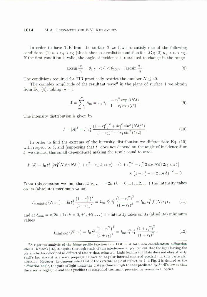
FIGURE 3. The contrast function C(N, /1) nf LGI "5. N al a given R (= 0.7,0.8,0.9,0.95).
In Eg. (11) we introduced the funetion
(1 - 1'n2f (N, 1'¡) = (1 + ,.¡) ---I - 7'1
where the relation ti + 1'i = I has heen used.From Egs. (11) ami (12) we lind the eontr'L,t I"uuetion as fol!ows:
e (N, 1'¡) = lm",(abs) (N) = _(I_+~7'_¡)_:(i - 7'n: = e (()(v¡) (i - 1'n:,lmin(abs) (N) (1 - 1'¡) (1+ 1'f) (1 + 1'f)
(13)
(14)
where we introduce the eontrast funetion e (00, ",) for all illfinite number of interferingrays, when "1 < 1 and N -+ oo.
Thc other characteristic of an interfcrence pa.tterll, which is of practical interest, isthe ratio of lmax(abs) (N, ,.¡) to the illtellsity of illcidellt ¡¡ght linc' We cal! it the efficieneyfunetion E (N, "1), 111the eonsidered e'L,e, we have lhe fol!owing rdaliol1s belween theaJnplitudes and coefficiellts of rcflection alld transmission: Aa = Aine t~, ti + r? = 1,10= IAol2 = linc t~2 Thns, lhe efliciency 01"LGI wilh TIR fmm the lower surfaee is egualto
1 (N) (V)2E (N, 1'¡) = _,_"_,,,_(a_b_s)__ = t;2 (1 + "1) _1_-_'_'1_ == t;2 f (N, 7'¡) .
fine 1 - 1'1(15 )
We note that the contrast of an interl"erenee pattern depends only on the number ofinterfering beams N and on the reneetion coeflieienl 1', 01"lhe surfaee 1 from inside al1interferometrie deviee, for hoth LG and FP schemes [see Eq. (14)]. Jt does 110t dependon the conditions at the entran ce of a device, in olher words, of linc t~2Bul, both thehrightl1ess [lmax(abs) (N, ,.,) and lmin(abs) (N, 1'¡)] and the efliciency E (N, 1'¡) in fringesdepend also on the conditions al lhe entranee of the deviee.
In the considered case of LG device with a total intemal re!leclion, we suppose thatthe number of interfering beams does nol exeeed 50. The plots of the eontrast e (N, 1'¡) asa function of N al given values of R = ti = (0.7,0.8.0.9,0.95) have c1early demonstratedthat e (N. "1) is a monolonieal1y incre'L,ing fnnetion of N (see Fig. 3).
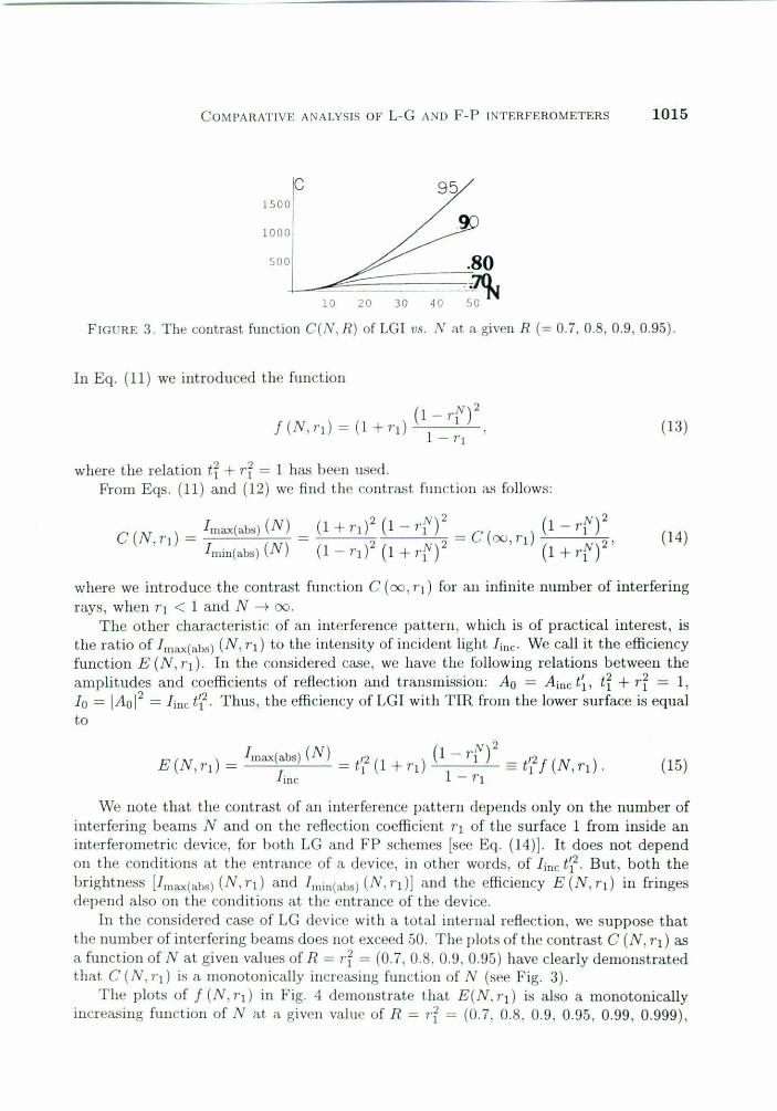
The plots of f (N, 1'1) in Fig. 4 demon,lrate tha! E(N,1'¡) is also a mOl1otol1ical!yinereasing funetion of N at a given value of R = "i = (0.7. O.S, 0.9, 0.95, 0.99, 0.999),
1016 M.A. CERVANTESANDE.V. KURMYSHEV
10 20 30 40
.99ce7
099950 N
40 f
30
20
10
FIGURE4. The function ¡(N, R),Eq. (13), of LGI VS. the number refiectionsN < 50 at differentvalues of the refiection coefficientR = 0.7, 0.8, 0.9, 0.95, 0.99, 0.999.
but when R -+ I the value of E(N, r¡) at a given N tends to O. The etalon becomes awaveguide in the considered limit case and does not permit light to go out of the gap. Itis easy to show that
(1 N)2limj (N,r) = lim - r - 0,r-+l r-¡.l 1 - r
(16)
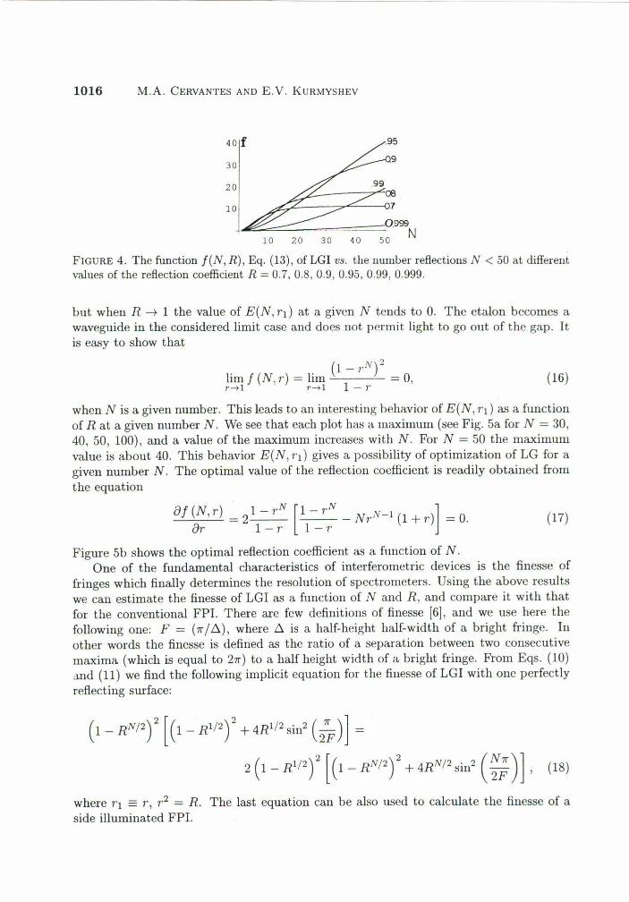
when N is a given number. This leads to an interesting behavior of E(N, r'l) as a functionof R at a given number N. We see that each plot has a maximum (see Fig. 5a for N = 30,40, 50, 100), and a value of the maximum incr"'tses with N. For N = 50 the maximumvalue is about 40. This behavior E(N, r¡) gives a possibility of optimization of LG for agiven number N. The optimal value of the refiection coefficient is readily obtained fromthe equation
oj (N,r) = 21 - r.N [1- r.N _ NrN-l (1 + r)] = O.or I-r I-r
(17)
Figure 5b shows the optimal refiection coefficient as a function of N.One of the fundamental characteristics of interferometric devices is the finesse of
fringes which finally determines the resolution of spectrometers. Using the aboye resultswe can estimate the finesse of LGI as a function of N and R, and compare it with thatfor the conventional FPI. There are few definitions of finesse [6]' and we use here thefollowing one: F = (1r/6.), where 6. is a half-height half-width of a bright fringe. Inother words the finesse is defiried as the ratio of a separation between two consecutivemaxima (which is equal to 21r) to a half height width of a bright fringe. From Eqs. (10)"nd (U) we find the following implicit equation for the finesse of LGI with one perfectlyreflecting surface:
( 1 _ RN/2) 2 [ (1_ R'/2) 2 + 4R'/
2 sin2 (2~)]2 (1 - R'/
2f [(1 - RN/2f + 4RN/2 sin2 (~;)], (18)
where r, == r, r2 = R. The last equation can be also used to calculate the finesse of aside illuminated FPI.
COMPARATIVEANALYSISOP L-G ANDF-P INTERPEROMETERS 1017
0.6 0.7 0.8
(a)0.9
f806040
20R
1 R
O. B
O. ,
0.620 40 ;O-~B'~O-'.00 N
(b)FIGURE5. (a) The function ¡(N, R) of LG! vs. the reflection coefficient R at a given number ofreflections N(= lO, 20, 30, 40, 50, 100). (b) The optimal value of the reflection coefficient R fordifferent numbers of reflection N inside LGL
60 F
40
30
20
10
200 F
150
10
R0.75 O.H 0.85 0.9 0.95
(a)0.75 O.H 0.85 0.4 0.95
(b)
R
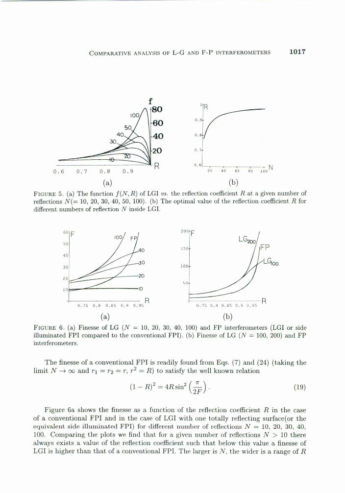
FIGURE 6. (a) Finesse of LG (N = lO, 20, 30, 40, 100) and FP interferometers (LGI or sideillurninated FP! cornpared to the conventionai FPI). (h) Finesse of LG (N = lOO,200) and FPinterferometers.
The finesse of a conventioual FPI is readily found from Eqs. (7) and (24) (taking thelimit N -+ 00 and r¡ = "2 = r, r2 = R) to satisfy the well known relation
(! - R)2 = 4Rsin2 C~). (19)
Figure 6a shows the finesse as a fuuction of the reflection coefficient R in the caseof a conventional FP! and in the case of LG! with one totally reflecting surface(or theequivalent side illuminated FPI) for diffcrent numhcr of rcflcctiollS N = 10, 20, 30, 40,100. Comparing the plots we find that for a giveu uum!>er of reflections N > 10 therealways exists a value of the reflection coefficient such that helow this value a finesse ofLG! is higher than that of a conventional FPI. The larger is N, the wider is a range of R
1018 M.A. CERVANTES ANO E.V. KURMYSHEV
where the finesse of a LG is greater than that of the FP. Fig. 6b shows that the finesseof LGI with lOO reflections is higher than that of the conventional FPI in the range ofR < 0.97.
It is possible that the number of interfering beams be very large when the angle ofincidenee is small. This condition can be met when the lower surface obtains the desiredrefleetanee by use of multilayer dieleetric coating to aehive a refleetanee approaehingunity, 1'2 = 1. When, at a given R < 1, the n\lmber N -+ 00, the Eqs. (11), (12), (14)and (15) provide us the following results:
2 1 12 1 - rilmax(abs) (00, 1'¡) = lo tI 2 = line tI 2
(1 - rl) (1 - rl)
121+ rl= line tI -- > lmax(abs) (N, r¡),
1 - rl
2 1 121 - 1'1lmin(abs) (00, rl) = lo tI 2 = line tI -- < lmin(abs) (N, r¡) ,
(1 + rl) 1+ rl
e ( )- lmax(abs) (00, r¡) _ (1 + 1.¡)2 > e (N )00, TI - , - 2 ,1'l ,
lmin(abs) (00,1¡) (1- r¡)
E ( ) _ lmax(abs) (00, r¡) _ t'2 1 + rl > E (N . )00,1'1 - l - 1, ,11 .
¡nc 1-11
(20)
(21 )
(22)
(23)
These set of equations shows \lS a better perfonuace of LGI with N -+ 00 as eomparedto the case of LGI with the finite number of reflections.
4. FABRy-PEROT BASED INTERFEROMETRY
There are three cases we will eonsirler: (a) the eonventional FPI, (b) a side ill\lminatedFPI, (e) a side illuminaterl FPI with (lIle surfaee totally reflecting.
The eonventional FPI is speeified by the following parameters: rl = r2 == r < 1 andN -+ 00, Aa = Aine t~, here tI = t = t2 ane! t~ = t; (= t), amI t2 + r2 = 1, R = r2 UsingEq. (7) at N -+ 00 we can easily find, for au interferenee pattern in transmitted light,the well known relations [6]
1 2 1 122 1 121 ()lmax(abs) (00, R) = lo t2 (1 _ R)2 - line tI t (1 _ Rl - line tI 1 _ R = line, 24
1 2 1 12 l-R (I_R)2lmin(abs) (00, R) = lo t2 (1 + R)2 - line tI (1 + R)2 = line 1+ R (25)
e (00, R) = l:;ax(abs) (00, R) = (1+ R) 2 (26)lmin(ab') (00, R) 1 - R
E (00, R) = l:nax(abs) (00, R) = t? _1_ = 1. (27)line 1 - R
\
COMPARATIVE ANALYSIS OF L.G AND F.P INTERFEROMETERS 1019
A cOlllparison of Eqs. (ll), (20). (24), Eqs. (14), (22), (26), and E'Is. (15), (23), (27)leads to the conclusion that LGI can providc an appreciable gaill in luaxinmm illtensityof the bright fringes, in contrast and in etfieiency as compared to that for a conventionalFPI, even when a LGI has a finite nnmher of interfering rays.
As is well known, the FPI interference pattern in translllitted light consists of brightfine fringes in a dark hackground. Reflected light produces the complelllentary pattern,namely, fine dark fringes on a hright hackground, this is particularly due to the firstexternal reflection suffered by the iucident heam which is relatively strong. For practicalreasons the transmitted pattern is preferred over the reflection one because it is lessnoisier with regard to the detection system.
The patterns in a conventional FPI are substantially different when the first externalreflection is avoided. The incoming light can he admited into the interferometer with socalled side ilhunination. A side illuminated FPI is conceptually equivalent to a LG, theonly difference between them is that a medium hetween reflecting planes is a solid in aLGI while it is usually air in the case of FPI. Thus, an interference pattern of a sideillulllinated FPI observed in reflected light (which is very similar to that in a transmittedlight) is described hy Eqs. (4) and (5), where we have to take Ao = Aine and 10 = line. Inthe case of transmitted light pattern we can use Eqs. (6) and (7), substituting Ao = Aincami 10 = line in it.
In the ca", of a side iluminated FPI with 1'1 < 1, 1'2 = 1 and N -+ 00, an interferencepattern ohserved in reflected light is descrihed hy Eqs. (20)-(23), where we have to taket~2= 1, i.c., Av = Aiuc <111d lo = filie.
\Ve note that. a large rcflcctioll allgle illlplies IIccessarily el. small Ilumber of rcflections,whcra ..''¡ a small angle pcnllits liS to use a largcr llllIllber of interfering beams. Now, in aside illulllinated FPI or LGI, the allgle needs to he small to have N 'LSlarge as possiblebut this IllCallS that thc ovcrlappillg 01' the hcitms is of slllall eross sectioll. Thereforc,a sidc illulllinatcd illtcrferomcter, itl U¡e ca ..'~;(~N -+ 00, he it él LGI 01' él FPI, have aninellicient elllploymellt of the incidellt !>eam. Tite re'L"Jll is that becanse of a small allgleof incidence, needed to provide mnltiple (illtinite) reflectiolls inside an interferometer,one penllits ollly a small part of the illcident heam to ent.er inside it, and ollly this partfurther contri!>ntes to form all illterferellce pat.tern. Tite major part of the incident beamis lost.
5. CONCLUSIONS
The two !>'Lsicinterferometric mnltiple !>eam schemes of optics, Lnmlller.Gehrcke andFa!>ry-Perot, have beell allalyzed he re 011 t.he IliLSisof theoretical scheme which permits asimilar consideration fOl' hoth type of interferometric schemes. We demonstrated that aLGI with one totally reflecting surface 'L' well as a side.illnminated FPI with OIle totallyref1ectillg surface can providc au appreciable gaill in maximulIl intcllsity of bright eringes,in cOlltrast alld iu cfficicllCY. in comparisoll lo that [01' the COllvclltional FPI, even whell aLGI ha..,;;a flnitc Ilumber of intcrfcring rays. \Ve also (lClllollstratcd that fOl"a giVCll finitelltUllbcr of rcflections insidc au intcrferomctric cavity therc always exists au optiInal re-fiection cocfficicnl which provides tlle IllltxiJIllllll dficicncy (the ratio bclwecn a maxiIllulll
intcllsity in a bright eringe aul! au intcnsity of illci<icnt bcalll) of au illlerferomclric dt..vice.
1020 M.A. CERVANTES AND E.V. KURMYSHEV
REFERENCES
1. C. Fabry and A. Perot, Ann Chim. Phys. 16 (1989) 115.2. C. Fabry and A. Perot, Astrophys. J. 10 (1901) 265.3. O. Lummer, Ann. Physik Chem. 23 (1884) 49.4. O. Lummer, Verh. Deutsch Phys. Ces. 3 (1901) 85.5. O. Lummer and E. Gehrcke, Ann. d. Physik, (4) 106. G. Hemández, Fabry Perat Interferameters, (Cambridge University Press, London, 1986).7. C. Candler, Modem Interferameters, (Hilger & Watts, London, 1951).8. M. Cervantes and O.L. Orozco-Lázaro. 6ptica 2 (1992) 23.9. E. Bernabeu and L.L. Sánchez Soto, Joumal Of Optics 17 (Paris) (1986) 283.10. T.T. Kajava, H.M. Lauranto, and A.T. Friberg. JOSA A 11 (1994) 2045.11. H.P. Waran, Praceedings of the Royal Society 100 (1922) 419.12. E. Lau, Zeitschrijt für Instrumentenkunde 49 (1929) 57.13. E. Lau, Zeitschrift für Tech. Phys. 8 (1927) 537.14. L.W. Blau and R.R. Thompson, Zeitscrift für Instrumentenkunde. 49 (1929) 416.15. C. Dufour, C. Revue D'Optique 24 (1945) 11.16. F. Kolacek, Ann. Phys., Lpz. 39 (1912) 1431.