Embed Size (px)
Citation preview

U.P.B. Sci. Bull., Series C, Vol. 79, Iss. 3, 2017 ISSN 2286-3540
COMPARATIVE ANALYSIS OF SOLAR PHOTOVOLTAIC
FED Z-SOURCE INVERTER BASED UPQC FOR POWER
QUALITY ENHANCEMENT
Miska PRASAD1, Ashok Kumar AKELLA2
This paper presents a solar photovoltaic (SPV) fed Z-source inverter (ZSI)
based Unified Power Quality Conditioner (UPQC) for the alleviation of power quality
events such as voltage sags and harmonics with sudden addition of a nonlinear load.
A novel hybrid technique was also proposed for optimum maximum power point
tracking (MPPT) with the combination of perturbation and observation (P&O) and
incremental conductance (Inc) technique. The response of SPV fed ZSI-UPQC for
mitigation of supply voltage sags and harmonics are investigated and compared with
SPV fed voltage source inverter (VSI) based UPQC (VSI-UPQC) and SPV fed current
source inverter (CSI) based UPQC (CSI-UPQC).
Keywords: Power quality, Voltage sag, Harmonics, UPQC, Photovoltaic.
NOMENCLATURE
k=Gain
Vm=Peak Amplitude of the fundamental input voltage
Ua, Ub, Uc=Unit Vector
Vdm=Desired load voltage magnitude
V*La, V*
Lb, V*Lc=Reference load voltage
VSa,VSb, VSc=Source voltage
V*Cabc=Reference compensator voltage
VCabc=Measured compensator voltage
I*Sa, I*
Sb, I*Sc=Reference source current
ISa, ISb, ISc=Source current
I*Ca, I*
Cb, I*Cc=Reference shunt compensator current
ICa, ICb, ICc=Measured shunt compensator output current
Ipc=Photovoltaic current
gK=Solar irradiation
To=Operating temperature
Tref=Cell temperature
ISC= Cell Short circuit current
Idiode=Diode current
1 Research Scholar, Department of Electrical Engineering, National Institute of Technology
Jamshedpur, India, e-mail: [email protected] 2 Associate Professor, National Institute of Technology Jamshedpur, India, e-mail:

124 Miska Prasad, Ashok Kumar Akella
Vpv=Output voltage of the PV
Ipv= Out current of the PV
RS=Series resistance
n=Diode identity factor
Vt= terminal voltage
C=No of cells
nS=No of PV panels in series
nP= No of PV panels in series
Idr=Diode reverse saturation current
Irs=Diode reverse current
Ish=Short circuit current
a=Transformation ratio
t=time
VS=Supply voltage
Vinj=Injected voltage
Vload=Load voltage
VC= Capacitor voltage
IL=Inductor current
1. Introduction
In recent years, many researchers have given their focus on voltage and
current quality. Among all disturbances, the voltage sags, and voltage swells
represent the most common, frequent and vintage power quality degrading factors
in these days power system [1-3]. UPQC is one the key Custom Power Devices
(CPDs) which can compensate voltage and current distortions simultaneously [4-
6]. Generally, the UPQCs consist of VSI [7-9], CSI [10] and ZSI for the alleviation
of voltage sags, swells, and harmonics. The VSI is buck (step-down) type so the
maximum output voltage is limited by DC link voltage. A condition of shoot
through would appear and damage the Insulated Gate Bipolar Transistor (IGBT)
switches if upper and lower switches of each leg of VSI fired on at the same time.
The CSI is a boost type so the voltage at output level is greater than the DC voltage
level. One of the big problems in CSI is that the open circuit across DC inductor
would appear and damage the IGBT switches if any instant of time at least of one
upper and lower switches cannot be fired on and keep it on. The demerits of
traditional converters such as VSI and CSI are discussed [11-12]. Therefore the
application of ZSI based UPQC technology seems very promising. ZSI has both
step-down and step-up facilities. Due to the presence of this unique character it
permits converters to be worked in the shoot-through condition [13]. Unlike a VSI
and CSI, the shoot-through state is not harmful and actually has been utilized in
ZSI. A great amount of research has been carried out in ZSI and its topologies.
Looking at the various advantages of ZSI over traditional converters it has decided

Comparative analysis of solar photovoltaic fed Z-source inverter based UPQC for power (…) 125
to study photovoltaic fed ZSI based UPQC (PV-ZSI-UPQC) and compare the
performance with that of PV-VSI-UPQC and PV-CSI-UPQC topologies.
The fossil fuels are the main source of fulfilled worldwide energy demand,
but at the same time due to increased price, environmental pollution, and global
warming have made it compulsory used renewable energy sources [9]. Renewable
energy such as solar photovoltaic seems to have an increasing importance because
it has several advantages, such as it has no noise or moving parts, and it does not
need any means of fuel [8]. It has low maintenance cost and it is environmental
friendly [14]. Despite these advantages, the I-V characteristics of a PV panel are
extremely nonlinear and alter with irradiation and temperature [15]. There is a solo
working point called maximum power point (MPP) on the I-V curve of the PV
panel. The PV panel produces its maximum output power and operates with a
maximum efficiency under certain irradiance and temperature conditions.
Therefore, MPPT techniques are needed to maintain an operating point of the PV
panel at its MPPT [16].
In this work, a novel hybrid technique also proposed for optimum MPPT
with the combination of P&O and InC techniques. The performance of PV fed
UPQCs depends on the control algorithm used for reference voltage and current
calculation. For the generation of a reference voltage and current signals currently
large numbers of control techniques are used. The commonly adopted techniques
are pq theory, synchronous reference frame (SRF) theory [1], [17-19] , Fuzzy Logic
Controller [20, 21], Resistive Optimization Technique [22] and Neural Networks
Technique [23]. This paper presents, a solar photo-voltaic (PV) fed impedance or
Z-source inverter based Unified Power Quality Conditioner (ZSI-UPQC) for the
mitigation of power quality issues namely voltage sags and harmonics and compare
the results with conventional PV fed VSI based UPQC (VSI-UPQC and) and PV
fed CSI based UPQC (CSI-UPQC). The Unit Vector Template (UVT) control
strategy is used to control the operation of PV fed UPQCs. Extensive
MATLAB/Simulink studies are performed for mitigation of short duration serious
voltage sags and source current and load voltage harmonics. Based on the
simulation results, the detailed comparative analysis is also done.
2. Configuration of UPQC
Fig. 1 depicts the power circuit configurations of the proposed SPV-ZSI-
UPQC. The power circuit of UPQC consists of two six leg impedance source
inverters joined back to back by a common dc-link produced by solar photovoltaic
with low step-up converter and a UVT control. The series part of SPV fed UPQC
is used to mitigate the destructive voltage disturbances namely voltage sags, swells,
fluctuations. Similarly the shunt part of SPV fed UPQC eliminates harmonics and
contributes reactive power compensation.

126 Miska Prasad, Ashok Kumar Akella
Three-phase
Supply
Vsabc
Lsa
Lsb
Lsc
Rsa
Rsb
Rsc
Rf Lf Rf Rf LfLf
Tr
Linear Load
Isa
Isb
Isc ILc
ILb
ILa
Lf
Lf
Lf
Rf
Rf Rf
S3S1 S5S7 S9
S11
S2 S4 S6 S8S10 S12
Tr Tr
S11
S12
Tr Tr Tr
S9S7
S10S8
S5S3
S6S4
S1
S2
L1
L2
C1C2
Unit Vector Template
Generation
Three-Phase Reference
Compensator Voltage
Generation
Three-Phase Reference
Compensator Current
Generation
Hysteresis Voltage
Controller
Hysteresis Current
Controller
VSa VSb VSc
Ua Ub Uc
PI
Controller +
Limiter
Vdc
Vdc*
PV Panal
DC-
DC
Conve
rter
ZSI
Diode
Vdc
VCa*
VCb* VCc
*VCc
VCb
VCa ICa
ICb
ICc
ICc*ICb
*ICa*
UPQC
Fig. 1. Schematic diagram of SPV fed ZSI-UPQC
3. Control philosophy
The performance of PV fed UPQC system totally depends on its control
technique for generation of a reference voltage and current signals. In this work
UVT control technique is used to generate the reference voltage and current signals
for both series and shunt active power filters.
3.1. Control technique for series active power filtar
Fig. 2 shows the Unit Vector Template (UVT) based control algorithm of
series part of UPQC for the production of reference voltages. The distorted supply
voltages are measured and multiplied by the gain k, which is equal to (1 / Vm ).
Where Vm is the peak amplitude of fundamental input voltage is calculated by using
equation (1).

Comparative analysis of solar photovoltaic fed Z-source inverter based UPQC for power (…) 127
-+
-+
-+
VSa
VSb
VSc
k=1/Vm
k=1/Vm
k=1/Vm
Three-
Phase
Phase
Locked
Loop
(PLL)
Sin(ωt)
Sin (ωt-2*pi/3)
Sin (ωt+2*pi/3)
Desired
Load
Voltage
MagnitudeVdm
Ua
Ub
Uc
VLa*
VLb*
VLc*
VSa
VSb
VSc
VCa*
VCb*
VCc*
VCcVCb VCa
a
a
a
gain
gain
gain
Hysteresis
Voltage
Controller
Fir
ing P
uls
es
Fig. 2. UVT control technique for Series Active Power Filter
2 2 22 / 3V V V Vm Sa ScSb (1)
The obtained supply voltages are passed to phase locked loop (PLL). The
main function of PLL is to maintain the synchronization with supply voltage and
produce a unit vectors ( , ,U U Ua cb) is obtained by using equation (2).
2 / 3
2 / 3
U Sin ta
U Sin tb
U Sin tc
(2)
The reference load voltage waveforms are produced by multiplying the
computed three in phase unit vector template with the desired load voltage
magnitude Vdm
is given in equation (3).
*
*
*
VLa Ua
V V ULb dm b
UcVLc
(3)
The obtained reference load voltages ( * * *, ,V V VLa LcLb
) are compared with
three-phase source voltages ( ,,
V V VSa ScSb
) and multiplied with ‘a’, where ‘a’ is the
transformation ratio of a series transformer and produces reference compensator

128 Miska Prasad, Ashok Kumar Akella
voltage ( *V
Cabc). The reference compensator voltage and measured series
compensator output voltage (Cabc
V ) are then given to hysteresis voltage controller
to produce the firing signals.
3.2. Control technique for shunt active power filter
The working of UVT strategy for shunt active power filter is similar to the
series active power filter but in shunt active power filter additionally compares the
measured dc-link voltage with reference dc-link voltage as shown in Fig. 3. The
obtained error is given as input to a proportional integral controller and generates
an output signal which is multiplied with UVT and produces reference source
current waveforms is given in equation (4).
*
*
*
ISa Ua
I I UmSb b
UcISc
(4)
The obtained reference supply current signals are compared with supply
current signals and generates reference output current of shunt compensator (* * *
, ,I I ICa CcCb
) and these signals are given to hysteresis current controller along with
the measured shunt-compensator output currents ( , ,I I ICa CcCb
).
-
+
-+
-+
VSa
VSb
VSc
k=1/Vm
k=1/Vm
k=1/Vm
Three-
Phase
Phase
Locked
Loop
(PLL)
Sin(ωt)
Sin (ωt-2*pi/3)
Sin (ωt+2*pi/3)
Ua
Ub
Uc
ISb
ISc
Hysteresis
Current
Controller
Fir
ing P
uls
es
-
+Vdc
Vdc*
Kp+ Ki/s
PI
Controller
Limiter ISa
ISb*
ISc*
ISa*
ICa*
ICb*
ICc*
ICcICa ICb
Fig. 3. UVT control technique for Shunt Active Power Filter
4. Modeling of solar photovoltaic (PV)
PV system presents an alternative solution for electricity supply especially
for remote locations because of low maintenance requirement, high reliability, long

Comparative analysis of solar photovoltaic fed Z-source inverter based UPQC for power (…) 129
life, and stability with un-rotating units [24]. The basic diagram for modeling the
solar PV system is depicted in Fig. 4.
E
Cg
Hybrid MPPTPWM
Generator
IGBT
Diode
DiodeRS
RSh
L
IdiodeIshIpc
Ipv
VpvVdc
PV Pannel DC-DC Converter
gk
+
- -
+
Go to VSI/CSI/ZSI
UPQC
Fig. 4. PV modeling with step-up dc-dc converter and hybrid MPPT algorithm
The basic equation of the PV cell is defined in the equation (5).
I I n I Ipc pPV diode sh (5)
Where PCI is a photocurrent mainly depends up the solar irradiation and
cells working temperature, which is described in the equation (6)
I g I K T ToiKPC SC ref
(6)
Where gK is a solar irradiation in kW/m2 , To is the cell operating
temperature, Tref
is the cell temperature at 25˚C and ISC
is the cells short circuit
current. The current following to the diode is represented by equation (7)
1
V I RPV PV S
nV Cnt SI e I nPdiode dr
(7)
Where Idiode
is the diode current, VPV is the output voltage of the PV
panel, IPV is the output current of the PV panel, R
Sis the series resistance, n is
the diode identity factor, Vt is the terminal voltage, C is the number of cells in PV
panel, nS
is the number of PV panels in series, nP is the number of PV panels in
parallel and Idr
is the diode reverse saturation current. The diode reverse saturation
current is defined in the equation (8).

130 Miska Prasad, Ashok Kumar Akella
1 13qE
bT Tnk o refToI I ersdr T
ref
(8)
Where Irs is the diode reverse current at operating temperature, q is the
charge of an electron, bE is the band-gap energy of the cell and k is the Boltzmann’s
constant. The shunt current Ish
obtained from the equivalent circuit of PV module
is given in the equation (9).
V I RPV PV SI
sh RP
(9)
After putting the values of Idiode
and Ish
from equations (7) and (9) in
equation (5), we obtained equation (10).
1
V I RPV PV S
nV Cn V I Rst PV PV SI I n e I npc p pPV dr RP
(10)
5. Maximum power point tracking (MPPT) technique
The MPPT is the heart of the solar PV system. This paper also proposed a
hybrid MPPT algorithm with a combination of P&O and InC with a dc-dc converter
is integrated to measure the optimum maximum power point from the solar system.
5.1 Proposed hybrid MPPT technique
Hybrid MPPT technique is proposed to eliminate the limitations of both
P&O and InC techniques is highlighted in Fig. 5. The objective of this proposed
technique is to obtain the combine advantages of P&O and InC techniques. This
scheme is used to calculate the output power after measuring the voltage and current
from the solar system. Then it compares the power with a previous value of power
by finding the change in power. The proposed algorithm checks whether ΔI/ΔV is
greater than, less than or equal to –I/V and gives its decision whether to increase or
decrease the terminal voltage. Fig.6 highlightes the flowchart of the proposed
MPPT technique.

Comparative analysis of solar photovoltaic fed Z-source inverter based UPQC for power (…) 131
Voltage (V)
Pow
er (W
)
VOCVMax
PMax
MPP
0,0 10 15 20 25 30
30
60
90
120
150
dI/dV> -I/V
dI/dV< -I/V
P<PMax
V>VMaxP<PMax
V<VMax
Fig. 5. Power-Voltage (P-V) characteristics of the hybrid MPPT technique
Start
Measure: V(m) and
I(m)
Copmpute:
P(m)=V(m)*I(m)
ΔP (m)=P(m)-P(m-1)
ΔV(m)=V(m)-V(m-1)
ΔI(m)=I(m)-I(m-1)
ΔP(m) = 0
ΔP(m) > 0
ΔV(m) > 0 ΔV(m) > 0
ΔI(m)/ΔV(m) > -
I(m)/V(m)ΔI(m)/ΔV(m) > -
I(m)/V(m)
ΔI(m)/ΔV(m) > -
I(m)/V(m)
ΔI(m)/ΔV(m) > -
I(m)/V(m)
Decrease Increase Decrease Decrease DecreaseIncrease Increase Increase
update history:
P(m-1) = P(m)
V(m-1) = V(m)
I(m-1) = I(m)
Return
Yes
No
No
Yes
Yes Yes
Yes Yes Yes YesNo No No No
No No
Fig. 6. Flowchart of the proposed hybrid MPPT technique
6. Simulation results and discussion
To show the effectiveness of the PV fed VSI, CSI and ZSI based UPQCs
with its associated UVT control technique and the power circuit given in Fig. 1 has

132 Miska Prasad, Ashok Kumar Akella
been established with MATLAB/Simulink software. The simulation parameters of
the system are depicted in table 1. To obtain the optimal maximum power point, the
new hybrid scheme with the combination of P&O and InC technique has been used.
The PV array with DC-DC converter gives greater output voltage as exposed in Fig.
7. Fig. 8(a-c) depicted that the proposed technique is more useful in extracting
maximum power point (MPP =152 W) from a solar PV system compared to a
maximum power point (MPP =151W) in a case of P&O technique and maximum
power point (MPP=151.58 W) in a case of incremental conductance method. The
most important goal of this section is to estimate the performance of the proposed
PV fed ZSI-UPQC in comparison with that of traditional PV fed VSI-UPQC and
CSI-UPQC for the alleviation of power quality events such as supply voltage sags
and supply current as well as load voltage harmonics. Table 1
Simulation parameters of the system
Parameters Values
Supply Voltage (Vs) 380 V
Frequency (f) 50 Hz
Supply Resistence (Rs) 0.05 Ω
Supply Inductance (Ls) 3.5 µH
Linear Load
Active Power (P)= 5Kw
Inductive reactive power (QL)= 10 kVAR
Nonlinear Load Diode rectifier, Rd= 10Ω, Ld= 3µH
Injection Transformer 240/120 V
DC-bus Voltage (Vdc) 150 V
No of solar cells 36
Normal voltage 40 V
Normal current 4.6 A
Step-up DC-DC converter
Inductance= 0.01H
İnput/output voltage= 40/150 V
Fig. 7. PV array output voltage without DC-DC converter and with DC-DC converter

Comparative analysis of solar photovoltaic fed Z-source inverter based UPQC for power (…) 133
Fig. 8. Comparison of MPPT (a) Perturb and Observe (b) Incremental conductance and (c)
Proposed Hybrid Technique
6.1 Performance of PV fed VSI-UPQC for mitigation of voltage sag
Due to sudden switching a nonlinear load, a three-phase voltage sag occurs
in the supply terminals of the distribution network from t=0.05s to t= 0.15s for
fourteen cycles of the supply voltage. For voltage sag of 15%, the supply voltage (
VS
), RMS supply voltage (RMS VS
), injected voltage ( VInj
), load voltage ( LoadV )
and dc-link capacitor voltage ( Vdc
) are observed and depicted in Fig. 9(a-e). For a
period of voltage sag only PV fed VSI-UPQC is connected to the system and
provide a correct amount of missing voltage quickly as shown in Fig. 9c and
minimize the effect of serious voltage sag so that load voltage become acceptable
level as highlighted in Fig. 9d.

134 Miska Prasad, Ashok Kumar Akella
Fig. 9. Simulation results of PV fed VSI-UPQC (a) supply voltage (b) RMS supply voltage (c)
Injected voltage (d) Load voltage and (e) DC-link Voltage
6.2 Performance of PV fed CSI-UPQC for mitigation of voltage sag
Fig. 10(a-e) shows the compensation effect of PV fed CSI-UPQC during
voltage sag condition. For voltage sag of magnitude 15%, the supply voltage ( VS
),
RMS supply voltage (RMS VS
), injected voltage ( VInj
), load voltage ( LoadV ) and
dc-link inductor current ( dcI ) are noted and highlighted in Fig. 10(a-e). The solar
PV fed CSI-UPQC comes into action for a duration of voltage sag event and
produces accurate voltage magnitude with proper polarity and introduce into the
distribution network. Due to this load voltage becomes insensitive to voltage sags
as shown in Fig. 10d. Fig. 10e demonstrates the variation of dc-link inductor current
during sudden switching a nonlinear load.

Comparative analysis of solar photovoltaic fed Z-source inverter based UPQC for power (…) 135
Fig. 10. Simulation results of PV fed CSI-UPQC (a) supply voltage (b) RMS supply voltage (c)
Injected voltage (d) Load voltage and (e) DC-link Current
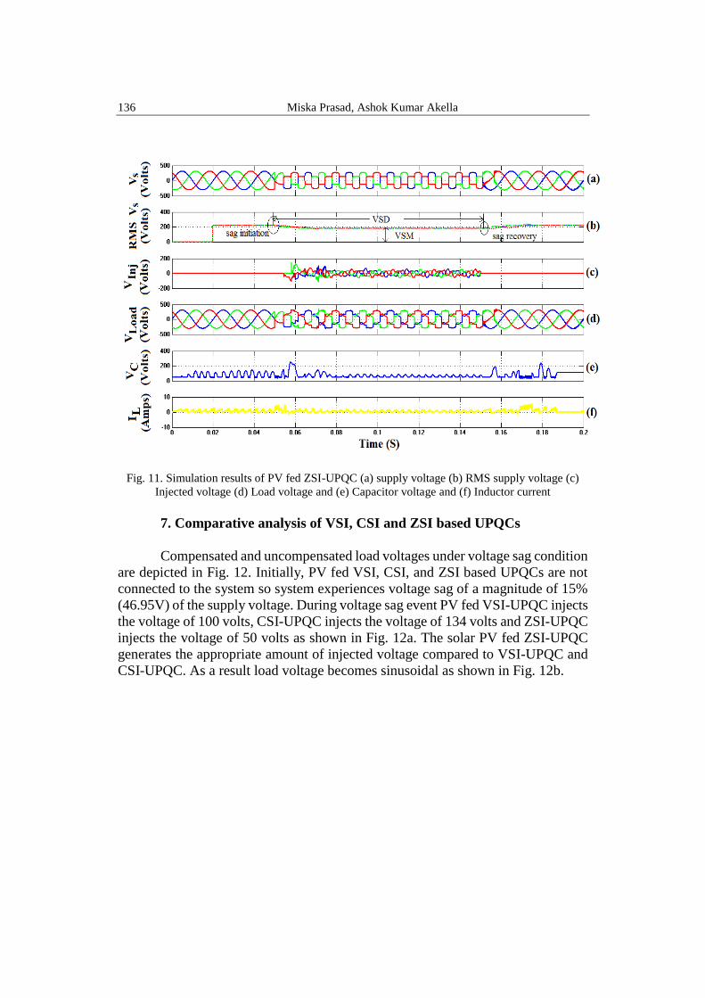
6.3 Performance of PV fed ZSI-UPQC for mitigation of voltage sag
Fig. 11(a-f) highlights the supply voltage ( VS
), RMS supply voltage (RMS
VS
), injected voltage ( VInj
), load voltage ( LoadV ), voltage across capacitor ( CV ) and
current in the inductor ( LI ) of PV fed ZSI-UPQC during voltage sag condition. A
three-phase balanced voltage sag of magnitude 15% encounters in the interval of
0.05 s ≤ t ≥ 0.15 s for fourteen cycles of the supply voltage as shown in Figs. 11a
and b. During voltage sag condition source voltage decreases and at t= 0.05s to t=
0.15s the PV fed ZSI-UPQC joined to the system and produces a right magnitude
of compensation voltage with correct polarity and eliminate the destructive voltage
sags as shown in Fig. 11c. As a result load voltage insensitive to supply voltage
disturbances as shown in Fig. 11d. The variation of capacitor voltage and inductor
current of PV fed ZSI-UPQC are highlighted in Figs. 11e and f.
136 Miska Prasad, Ashok Kumar Akella
Fig. 11. Simulation results of PV fed ZSI-UPQC (a) supply voltage (b) RMS supply voltage (c)
Injected voltage (d) Load voltage and (e) Capacitor voltage and (f) Inductor current
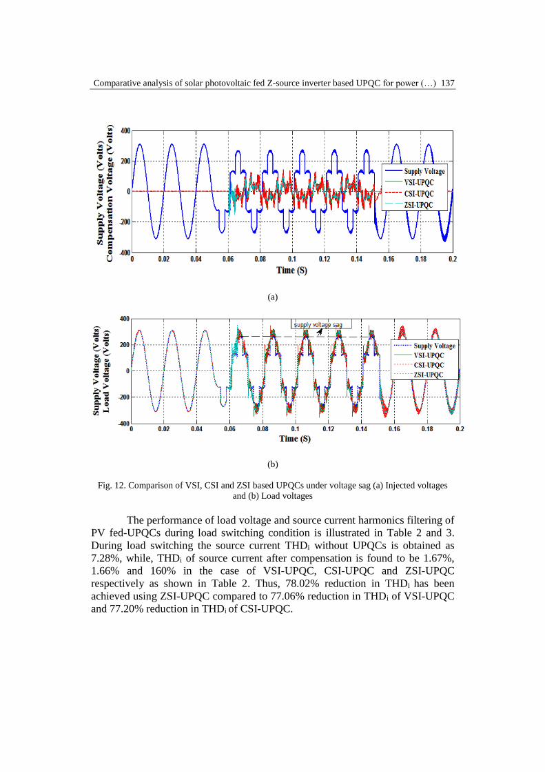
7. Comparative analysis of VSI, CSI and ZSI based UPQCs
Compensated and uncompensated load voltages under voltage sag condition
are depicted in Fig. 12. Initially, PV fed VSI, CSI, and ZSI based UPQCs are not
connected to the system so system experiences voltage sag of a magnitude of 15%
(46.95V) of the supply voltage. During voltage sag event PV fed VSI-UPQC injects
the voltage of 100 volts, CSI-UPQC injects the voltage of 134 volts and ZSI-UPQC
injects the voltage of 50 volts as shown in Fig. 12a. The solar PV fed ZSI-UPQC
generates the appropriate amount of injected voltage compared to VSI-UPQC and
CSI-UPQC. As a result load voltage becomes sinusoidal as shown in Fig. 12b.
Comparative analysis of solar photovoltaic fed Z-source inverter based UPQC for power (…) 137
(a)
(b)
Fig. 12. Comparison of VSI, CSI and ZSI based UPQCs under voltage sag (a) Injected voltages
and (b) Load voltages
The performance of load voltage and source current harmonics filtering of
PV fed-UPQCs during load switching condition is illustrated in Table 2 and 3.
During load switching the source current THDi without UPQCs is obtained as
7.28%, while, THDi of source current after compensation is found to be 1.67%,
1.66% and 160% in the case of VSI-UPQC, CSI-UPQC and ZSI-UPQC
respectively as shown in Table 2. Thus, 78.02% reduction in THDi has been
achieved using ZSI-UPQC compared to 77.06% reduction in THDi of VSI-UPQC
and 77.20% reduction in THDi of CSI-UPQC.

138 Miska Prasad, Ashok Kumar Akella
Table 2
Supply current harmonics THDi of VSI, CSI and ZSI UPQCs
Without
UPQCs
VSI-UPQC CSI-UPQC Proposed ZSI-UPQC
With
VSI-
UPQC
Improvement
in THDi (%)
With
CSI-
UPQC
Improvement
in THDi (%)
With
ZSI-
UPQC
Improvement
in THDi (%)
7.28 1.67 77.06 1.66 77.20 1.60 78.02
The THDv of load voltage measured without VSI, CSI, and ZSI based
UPQCs is observed as 25.96%, whereas the same is observed as 1.72% in the
presence of VSI-UPQC, 4.20% in the case of CSI-UPQC and 0.07% in the presence
of ZSI-UPQC as shown in Table 3. Thus, 93.37%, 83.82% and 99.73% reduction
in THDv have been achieved. The ZSI-UPQC shows the superior performance of
reduction in THDv in compare to VSI-UPQC and CSI-UPQC. Table 3
Load voltage harmonics THDs of VSI, CSI and ZSI UPQCs
Without
UPQCs
VSI-UPQC CSI-UPQC Proposed ZSI-UPQC
With
VSI-
UPQC
Improvement
in THDs (%)
With
CSI-
UPQC
Improvement
in THDs (%)
With
ZSI-
UPQC
Improvement
in THDs (%)
18.62 2.31 87.60 2.48 86.68 1.48 92.05
8. Conclusions
This paper highlights, a solar photo-voltaic (PV) fed three inverter
configurations of UPQC such as PV-VSI-UPQC, PV-CSI-UPQC, and PV-ZSI-
UPQC for the minimization of sags and harmonics with addition of a nonlinear
load. A novel hybrid method with the combination of P&O and InC technique is
also proposed. The proposed technique shows the superior performance to produce
maximum power output compared to P&O and InC techniques. The proposed
technique also controls the power loss by controlling the oscillations around the
MPP. The PV fed UPQCs is responsible for the fast and accurate production of
injecting voltage and injects it into the system for compensation of supply voltage
disturbances such as voltage sags. The obtained simulation results show that PV
fed ZSI-UPQC injects the appropriate amount of three-phase injecting voltage
compared to PV fed VSI and CSI based UPQCs. The simulation results also prove
that the proposed PV fed ZSI-UPQC shows a superior capability to annihilate the
source current and load voltage harmonics compared to PV fed VSI-UPQC and
CSI-UPQC.

Comparative analysis of solar photovoltaic fed Z-source inverter based UPQC for power (…) 139
R E F E R E N C E S
[1]. A.K. Panda, N. Patnaik, “Management of reactive power sharing & power quality improvement
with SRF-PAC based UPQC under unbalanced source voltage condition,” Electrical Power
and Energy Systems, vol. 84, 2017, pp. 182–194.
[2]. M. P. Kazmierkowski, R. Krishnan, F. Blaabjerg, “Control in Power electronics selected
problems,” Academic press, Amsterdam Bostom London, 2002, pp. 462-482.
[3]. P.R. Babu, P. K Dash, S.K Swain, S. Sivanagaraju, “A new fast discrete S-transform and
decision tree for the classification and monitoring of power quality disturbance waveforms,”
International Transactions on Electrical Energy Systems, vol.24, 2014, pp.1279-1300.
[4]. A. Basit, A.D. Hansen, M. Altin, P. E. Sorensen, M. Gamst, “Compensating active power
imbalances in power system with large-scale wind power penetration,” Journal of Modern
Power System and Clean Energy, vol.4, no.2, 2016, pp.229–237, 2016.
[5]. S.K. Khadem, M. Basu, M. F. Conlon, “A comparative analysis of placement and control of
UPQC in DG integrated grid connected network,” Sustainable Energy, Grids and Networks,
vol.6, 2016, pp.46–57.
[6]. X.U. Yunfei, X. Xiao, T. Sun, Y. Long, “Voltage sag compensation strategy for unified power
quality conditioner with simultaneous reactive power injection,” International Journal of
Modern Power system and Clean Energy, vol.4, no.1, 2016, pp.113-122, 2016.
[7]. P. Vodapalli, T.R.S Reddy, S.T. Kalyani, “A New Unified Power Quality Conditioner for Grid
Integration of PV System and Power Quality Improvement Feature Distribution System,”
IEEE International Conference on Electrical, Electronics, Signals, Communication and
Optimization (EESCO). 24-25 Jan. 2015.
[8]. A.R Reisi, M. H. Moradi, H. Showkati, “Combined photovoltaic and unified power quality
controller to improve power quality,” Solar Energy, vol.88, 2013, pp.154–162.
[9]. Y. Pal, A. Swaroop, B. Singh, “A comparative analysis of different magnetics supported three
phase four wire unified power quality conditioners – a simulation study,” Electrical Power
Energy System, vol.47, 2013, pp.436–47.
[10]. M.E. Pedro, J. R. Espinoza, C. R. Baier, J.I. Guzman, E.E. Espinosa, “Unified Power Quality
Conditioner based on Current Source Converters for Harmonic Mitigation using a Decoupled
Control Strategy,” IECON 2011 - 37th Annual Conference on IEEE Industrial Electronics
Society. 7-10 Nov. 2011.
[11]. M. Hanif, M. Basu, K. Gaughan, “Understanding the operation of a Z-source inverter for
photovoltaic application with a design example,” IET Power Electron, vol.4, no.3, 2011,
pp.278–287.
[12]. P. Kumar, N. Kumar, A.K Akella, “Comparative Analysis of Voltage and Current source
inverter based DSTATCOM systems,” Turkish Journal of Electrical Engineering and
Computer sciences, vol.24, 2016, pp.3838-3851.
[13]. M. Murali, P. Deshpande, B. Virpurwala, P. Bhavsar, “Simulation and Fabrication of single
phase Z-source inverter for resistive load,” U.P.B. Sci. Bull., Series C, vol.78, no. 1, 2016,
pp.112-124.
[14]. S. Sumathi, L. A. Kumar, P. Surekha, “Solar PV and Wind Energy Conversion Systems,”
Springer International Publishing Switzerland, 2015.
[15]. Y. Bouzelata, E. Kurt, R. Chenni, N. Altın, “Design and simulation of a unified power quality
conditioner fed by solar energy,” International journal of hydrogen energy, vol.40, no.44, ,
2015, pp.15267–15277.
[16]. S. Saravanan, N.R Babu, “Maximum power point tracking algorithms for photovoltaic system
– A review,” Renewable and Sustainable Energy Reviews, vol.57, 2016, pp.192–204.
140 Miska Prasad, Ashok Kumar Akella
[17]. N. Patnaik, A.K Panda, “Performance analysis of a 3 phase 4 wire UPQC system based on
PAC based SRF controller with real time digital simulation,” Electrical Power and Energy
Systems, vol.74, 2015, pp.212–21.
[18]. A.J Viji, T.A.A Victoire, “Enhanced PLL based SRF control method for UPQC with fault
protection under unbalanced load conditions,” Electrical Power and Energy Systems, vol.58,
2014, pp.319–28.
[19]. S.D.K.Varma, Y.P. Obelesh, Ch. Saibabu, “An Improved Synchronous Reference Frame
Controller based Dynamic Voltage Restorer for Grid Connected Wind Energy System,”
International Journal of Renewable Energy Research, vol.6, no.3, 2016, pp.880-888.
[20]. R.K Patjoshi, V.R Kolluru, K. Mahapatra, “Power quality enhancement using fuzzy sliding
mode based pulse width modulation control strategy for unified power quality conditioner,”
Electrical Power and Energy Systems, vol.84, 2017, pp.153–167.
[21]. M.A Kouadria, T. Allaoui, M. Denai, “Fuzzy control of a three-phase Shunt active power filter
for harmonic compensation in wind-diesel standalone system,” U.P.B. Sci. Bull., Series C,
Vol. 78, Iss. 4, 2016, pp.70-82
[22]. R.K Patjoshi, K. Mahapatra, “Resistive optimization with enhanced PLL based nonlinear
variable gain fuzzy hysteresis control strategy for unified power quality conditioner,”
Electrical Power and Energy Systems, vol.83, 2016, pp. 352–363.
[23]. S. Kasa, S. Ramasamy, “Photovoltaic fed Dynamic Voltage Restorer with Voltage Disturbance
Mitigation Capability Using ANFIS Controller,” International Journal of Renewable Energy
Research, vol.6, no.3, 2016, pp.825-832, 2016.
[24]. M. Mihai, A. Badea, R. Vidu, “Analysis of the PV system performance through simulation: a
case study,” U.P.B. Sci. Bull., Series C, vol. 78, no. 4, 2016, pp.184-194.