Embed Size (px)
Citation preview

Saharia et al., Cogent Engineering (2016), 3: 1137206http://dx.doi.org/10.1080/23311916.2015.1137206
ELECTRICAL & ELECTRONIC ENGINEERING | RESEARCH ARTICLE
Comparative evaluation of photovoltaic MPP trackers: A simulated approachBarnam Jyoti Saharia1, Munish Manas1* and Bani Kanta Talukdar2
Abstract: This paper makes a comparative assessment of three popular maximum power point tracking (MPPT) algorithms used in photovoltaic power generation. A 120 Wp PV module is taken as reference for the study that is connected to a suitable resistive load by a boost converter. Two profiles of variation of solar insolation at fixed temperature and varying temperature at fixed solar insolation are taken to test the tracking efficiency of three MPPT algorithms based on the perturb and observe (P&O), Fuzzy logic, and Neural Network techniques. MATLAB/SIMULINK simulation software is used for assessment, and the results indicate that the fuzzy logic-based tracker pres-ents better tracking effectiveness to variations in both solar insolation and tempera-ture profiles when compared to P&O technique and Neural Network-based technique.
Subjects: Electrical & Electronic Engineering; Engineering & Technology; Power Engineering
Keywords: PV; boost converter; perturb and observe; fuzzy logic; neural networks; tracking factor
1. IntroductionPower generation through photovoltaic (PV) generation system is one of the most sought after forms of renewable energy sources, popularity of which has been in the rise due to its non-polluting, renewable and inexhaustible nature (Eltawil & Zhao, 2013). Immense demand for finding feasible and environmental-friendly renewable energy sources to meet the future energy requirements as
*Corresponding author: Munish Manas, Department of Electronics Communication Engineering, Tezpur University, Assam 784028, India E-mail: [email protected]
Reviewing editor:Kun Chen, Wuhan University of Technology, China
Additional information is available at the end of the article
ABOUT THE AUTHORSBarnam Jyoti Saharia completed his MTech in power electronics and his research area is concerned with converter topology for MPPT algorithms. Currently he works as an assistant professor in ECE Department of Tezpur Central University in India.
Munish Manas is the recipient of meritorious UGC BSR fellowship for his research in microgrid design and optimization. Currently he works as an assistant professor in ECE Department of Tezpur Central University in India.
Bani Talukdar is a professor in Assam Engineering College and does his research in power system deregulation and system design.
PUBLIC INTEREST STATEMENTI am sending this manuscript for consideration for publication in your esteemed journal to assist the scientific community in the area of Comparative Evaluation of Photovoltaic MPP Trackers: A Simulated Approach. This paper makes a comparative assessment of three popular maximum power point tracking (MPPT) algorithms used in photovoltaic power generation. A 120 Wp PV module is taken as reference for the study that is connected to a suitable resistive load by a boost converter. Two profiles of variation of solar insolation at fixed temperature and varying temperature at fixed solar insolation are taken to test the tracking efficiency of three MPPT algorithms based on the Perturb and Observe, Fuzzy logic, and Neural Network techniques. MATLAB/SIMULINK simulation software is used for assessment, and the results indicate that the fuzzy logic-based tracker presents better tracking effectiveness to variations in both solar insolation and temperature profiles when compared to Perturb and Observe technique and Neural Network-based technique.
Received: 22 October 2015Accepted: 24 December 2015First Published: 15 January 2016
© 2016 The Author(s). This open access article is distributed under a Creative Commons Attribution (CC-BY) 4.0 license.
Page 1 of 17
Page 2 of 17
Saharia et al., Cogent Engineering (2016), 3: 1137206http://dx.doi.org/10.1080/23311916.2015.1137206
fossil fuel reserves deplete. Solar energy is a viable substitute to fossil fuels among other available renewable energy sources such as wind, hydroelectric, and geothermal power (Sivasubramaniam, Faramus, Tilley, & Alkaisi, 2014). Solar PV generators have been used in small-scale, stand-alone systems at low voltage levels as well as the high power installations, connected in grid mode and operating at medium or high voltage levels. The drawback of PV generators is its low conversion ef-ficiency (Sivasubramaniam et al., 2014). Efficiencies of typical crystalline PV cells are in the range of 12–18%, although experimental cells have been constructed that are capable of efficiency over 30% (Zaheeruddin & Manas, 2015a). The PV generators exhibit nonlinear current–voltage (I–V) and pow-er–voltage (P–V) characteristics (Liu, Liu, & Gao, 2013), a phenomenon that is more serious in par-tially shaded condition due to more than one maximum power point (MPP). For optimum use of PV generation, it is important to operate the system at the maximum available power production state for an available solar irradiation, temperature, and load. Thus implementation of maximum power point tracking (MPPT) control techniques, in order to maximize the available output from a PV gen-erator becomes an essential constituent of any PV system.
The MPPT involves operating a DC–DC controlled converter such that it leads to operates a PV sys-tem to its optimum power production state for given set of external atmospheric conditions and state of loading(Ahmed & Miyatake, 2008). Different algorithms employing tracking techniques for maxi-mum power from PV generators are found in literature. Jain & Agarwal, 2007; and Kim, 2007 uses sliding mode current controlled for power point tracking, by varying load voltage in order to obtain either the current derivative or voltage derivative equal to zero. Chih-Lyang, Li-Jui, & Yuan-Sheng, 2007 and Venelinov, Leonardo, Vincenzo, Francesco, & Okyay, 2007 make use of artificial intelligence techniques (fuzzy logic, neural network, and genetic algorithm) to determine the change in voltage and current of load, and in turn vary duty cycle for PWM control of the converter for effective tracking at any external atmospheric condition and loading. While most research works are focused on the development on the tracking algorithms, Bhattacharjee and Saharia (2014) make a comparative study on the individual converter topologies namely buck, boost and buck-boost converters used as interface in the PV power generators. They conclude that boost converter, when used as the power converter interface for MPPT, operates with better tracking effectiveness when operated at higher values of insolation. Tsang & Chan, 2015 make use of current sweeping-based approach for obtaining global maximum under partial shaded condition, which aids in controlling the large oscillations near the panel operating MPP and overcome methods otherwise problematical to implement using artifi-cial intelligent techniques. Li, 2015 proposes a MPPT method with variable weather parameters con-sidered specially from the input resistance perspective, in order to improve the tracking speed and adaptability to varying weather condition for PV systems. Hassan Fathabadi, 2015 proposes a Lambert W-function-based technique to evaluate the MPP of PV panels based on the current–voltage (I–V), power–voltage (P–V), and power–current (P–I) relationship of the PV module.
Artificial intelligence-based MPPT applications for solar energy have also been implemented for maximum power extraction from PV systems. (Iqbal, Ahmed, Abu-Rub, & Sinan, 2010; Kottas, Boutalis, & Karlis, 2006; Manas, 2015; de Medeiros Torres, Antunes, & dos Reis, 1998; Mellit & Kalogirou, 2008; Mellit, Kalogirou, Hontoria, & Shaari, 2008; Muralidhar & Susovon, 2015; Saleh, Chaaben, & Ammar, 2008; Sher et al., 2015; Zaheeruddin & Manas, 2015b; ) Among them, one of the most frequently preferred MPPT techniques is the perturb and observe (P&O) algorithm. Its advan-tages mainly include the low-cost hardware, the easy implementation and the good performance without solar irradiance and temperature varying quickly with time. Although highly popular due to its simplicity of implementation through electronic circuits, Hohm and Ropp (2003) (Hohm & Ropp, 2003) noted that only if properly optimized the P&O algorithm can overcome the shortcomings as-sociated with it including its slow tracking speed and oscillation around the MPP.
Most of the methodology of implementation of tracking algorithm involves complex circuitry and increase in the number of measured parameters. In order to negate the issue of complexity in im-plementation circuitry, Salah and Ouali (2011)(Manas, 2015) proposed fuzzy logic and neural net-work controllers. The controllers used the climatic parameters of insolation and temperature as

Page 3 of 17
Saharia et al., Cogent Engineering (2016), 3: 1137206http://dx.doi.org/10.1080/23311916.2015.1137206
inputs and estimated the optimum duty cycle corresponding to the system maximum power (Pmax). PV systems exhibit non-linear characteristics, which is appropriate for fuzzy logic-based control. Accurate rule base formulation between membership function of fuzzy logic controller leads to dy-namic and quick to respond output value of duty cycle that ensures MPP tracking. While neural net-works present the advantage of not requiring knowledge of the internal systems parameters, less computation time, and absence of complex algorithms for determining the optimum duty ratio. However, the effectiveness of this technique depends on the training of the system. The better the trained model, more accurate it is in predicting the operating duty cycle for MPP operation.
The MPPT algorithms works to automatically find the voltage at maximum power (Vmpp), the cur-rent at maximum power point (Impp) at which the PV array connected to a converter should operate to obtain the maximum power output under a given conditions of atmospheric insolation and tem-perature. The variation in the Vmpp and Impp with the change in insolation and temperature is a com-plex problem. This relation becomes more pertinent when there is partial shading, as it is possible to have multiple local minima, often at times resulting in error in the tracking of the MPP.
The three most popular and widely used MPPT tracking algorithms have been assessed in this study. The review of literature shows that although significant work has already been covered in development of P&O technique, fuzzy logic-based- and neural network-based controllers for MPPT applications, a comprehensive work on comparative assessment of the three techniques on a single PV system is not found in the literature. This article attempts to make a comparison based on the tracking effectiveness of each of the above-mentioned techniques to validate which tracking algo-rithms can give optimum performance under changing atmospheric condition.
The paper is presented in the following chronological order. Section 2 presents description on modeling of the PV module in SIMULINK and the theoretical foundation of the working of DC–DC boost converter. The methodologies related to the working of P&O technique, fuzzy logic-based con-troller design and neural network controllers are covered in Section 3. Section 4 presents two sce-narios where the controllers are tested with respect to their tracking effectiveness in simulation environment. Section 5 presents a short discussion on the tracking performance of the three refer-ence algorithms and Section 6 draws conclusion to the work.
2. PV System modeling and Operation of Boost ConverterIn this section, the mathematical modeling of the PV panel considered as the reference in this simu-lation study, namely the KYOCERA KC 120-1(Kyocera KC120-1 multi-crystalline photovoltaic module datasheet, 2015) is presented. The theoretical background on the operation of DC–DC boost con-verter is also presented here.
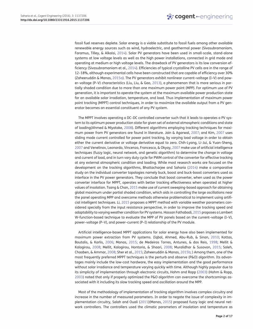
2.1. PV Module ModelingA solar cell is basically a p–n junction fabricated in a thin wafer of semiconductor. The electromag-netic radiation of solar energy can be directly converted into electricity through the PV effect. When exposed to sunlight, photon with energy greater than the band gap of the semiconductor creates the electron-hole pairs proportional to the incident radiation which is responsible for the generation of photocurrent.
Figure 1 shows the equivalent circuit of a PV cell. The current source Iph represents the photocur-rent. Rsh and Rs are the intrinsic shunt and series resistances of the cell, respectively. Usually the value of Rsh is very large and hence they may be neglected to simplify the analysis.
Each PV cell, when grouped together in a combination of parallel and series cells constitute a PV module and PV arrays. The mathematical Equations (1)–(4) are used for the modeling of the refer-ence PV module KYOCERA KC 120-1(Kyocera KC120-1 multi-crystalline photovoltaic module data-sheet, 2015).
Page 4 of 17
Saharia et al., Cogent Engineering (2016), 3: 1137206http://dx.doi.org/10.1080/23311916.2015.1137206
Module Photocurrent (Iph) is expressed by:
Module reverse saturation current (Irs) is given by:
The module saturation current (Io) varies with the cell temperature, which is expressed as:
The current output of the PV module (Ipv) is represented by:
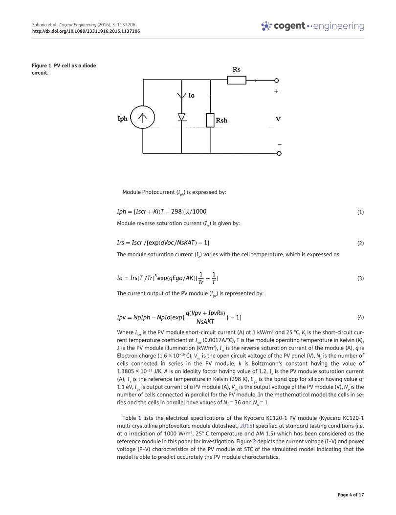
Where Iscr is the PV module short-circuit current (A) at 1 kW/m2 and 25 °C, Ki is the short-circuit cur-rent temperature coefficient at Iscr (0.0017A/°C), T is the module operating temperature in Kelvin (K), λ is the PV module illumination (kW/m2), Irs is the reverse saturation current of the module (A), q is Electron charge (1.6 × 10⁻¹⁹ C), Voc is the open circuit voltage of the PV panel (V), Ns is the number of cells connected in series in the PV module, k is Boltzmann’s constant having the value of 1.3805 × 10⁻²³ J/K, A is an ideality factor having value of 1.2, Io is the PV module saturation current (A), Tr is the reference temperature in Kelvin (298 K), Ego is the band gap for silicon having value of 1.1 eV, Ipv is output current of a PV module (A), Vpv is the output voltage pf the PV module (V), Np is the number of cells connected in parallel for the PV module. In the mathematical model the cells in se-ries and the cells in parallel have values of Ns = 36 and Np = 1.
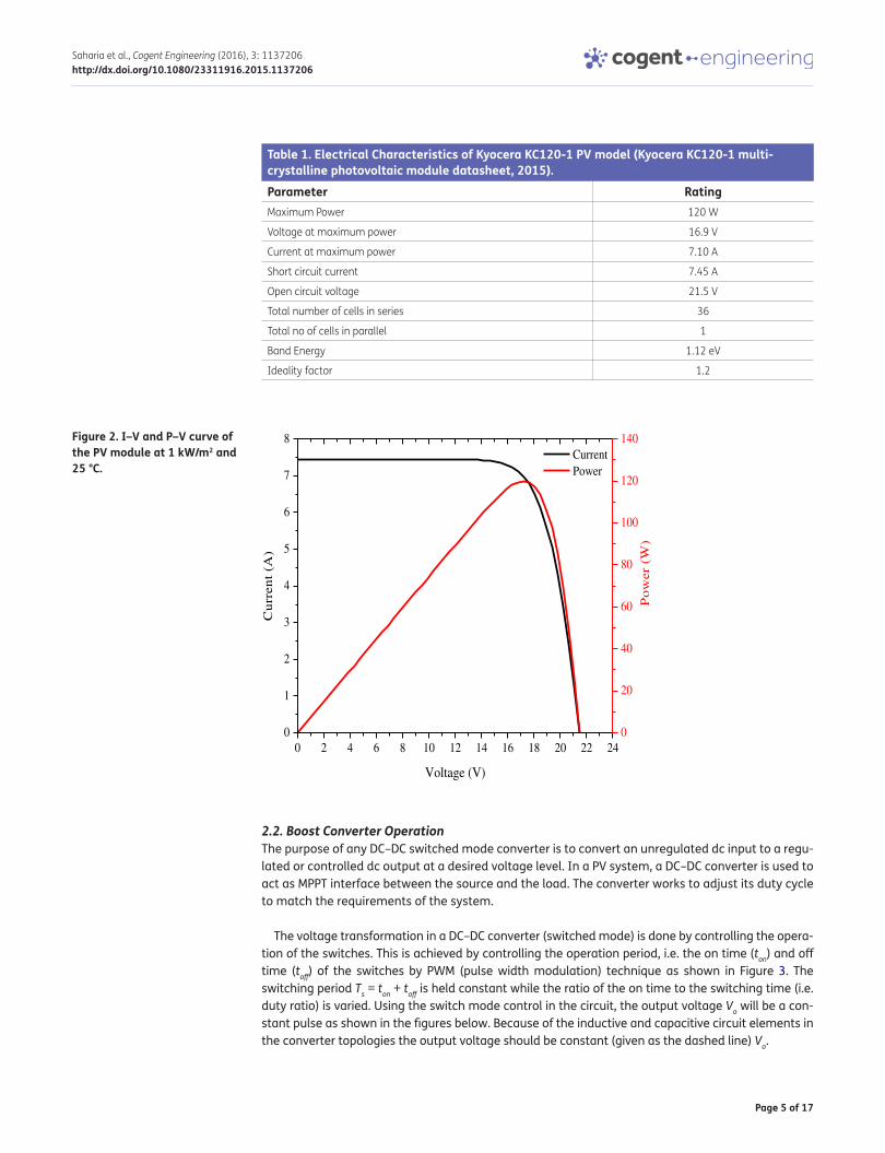
Table 1 lists the electrical specifications of the Kyocera KC120-1 PV module (Kyocera KC120-1 multi-crystalline photovoltaic module datasheet, 2015) specified at standard testing conditions (i.e. at a irradiation of 1000 W/m2, 25° C temperature and AM 1.5) which has been considered as the reference module in this paper for investigation. Figure 2 depicts the current voltage (I–V) and power voltage (P–V) characteristics of the PV module at STC of the simulated model indicating that the model is able to predict accurately the PV module characteristics.
(1)Iph = [Iscr + Ki(T − 298)]�∕1000
(2)Irs = Iscr ∕[exp(qVoc∕NsKAT) − 1]
(3)Io = Irs[T ∕Tr]3exp(qEgo∕AK)[1
Tr−1
T]
(4)Ipv = NpIph − NpIo[exp{q(Vpv + IpvRs)
NsAKT} − 1]
Figure 1. PV cell as a diode circuit.
Page 5 of 17
Saharia et al., Cogent Engineering (2016), 3: 1137206http://dx.doi.org/10.1080/23311916.2015.1137206
2.2. Boost Converter OperationThe purpose of any DC–DC switched mode converter is to convert an unregulated dc input to a regu-lated or controlled dc output at a desired voltage level. In a PV system, a DC–DC converter is used to act as MPPT interface between the source and the load. The converter works to adjust its duty cycle to match the requirements of the system.
The voltage transformation in a DC–DC converter (switched mode) is done by controlling the opera-tion of the switches. This is achieved by controlling the operation period, i.e. the on time (ton) and off time (toff) of the switches by PWM (pulse width modulation) technique as shown in Figure 3. The switching period Ts = ton + toff is held constant while the ratio of the on time to the switching time (i.e. duty ratio) is varied. Using the switch mode control in the circuit, the output voltage Vo will be a con-stant pulse as shown in the figures below. Because of the inductive and capacitive circuit elements in the converter topologies the output voltage should be constant (given as the dashed line) Vo.
Table 1. Electrical Characteristics of Kyocera KC120-1 PV model (Kyocera KC120-1 multi-crystalline photovoltaic module datasheet, 2015).Parameter RatingMaximum Power 120 W
Voltage at maximum power 16.9 V
Current at maximum power 7.10 A
Short circuit current 7.45 A
Open circuit voltage 21.5 V
Total number of cells in series 36
Total no of cells in parallel 1
Band Energy 1.12 eV
Ideality factor 1.2
Figure 2. I–V and P–V curve of the PV module at 1 kW/m2 and 25 °C.
0 2 4 6 8 10 12 14 16 18 20 22 240
1
2
3
4
5
6
7
8 Current Power
Voltage (V)
Cu
rren
t (A
)
0
20
40
60
80
100
120
140
Po
wer
(W
)

Page 6 of 17
Saharia et al., Cogent Engineering (2016), 3: 1137206http://dx.doi.org/10.1080/23311916.2015.1137206
The switch control signal is generated by comparing a control value (which mostly is a signal gen-erated as an error signal) to a repetitive waveform Vst. The control value may be the difference be-tween the actual and the desired output voltage Vo as seen by the Figure 3. The effects of comparison are when Vctr (Vcontrol) > Vst, switch is on and vice versa.
Hence, we can now define duty ratio (cycle) as
The frequency (1/Ts) can also be varied in a PWM switching mode. This method however might make it hard to filter the ripple components in the converter waveforms.
In a DC–DC converter with an optimal design, it is assumed that the switching ripples are very small compared to the average values often less than 1% of the quantities. This is often referred to as the small or linear ripple approximation. The boost converter produces an output voltage which is higher than the input voltage.
(5)D =ton
Ts=Vctr
Vst
Figure 3. Switch mode operation of converters.
Figure 4. PWM block diagram and comparator signal.
Page 7 of 17
Saharia et al., Cogent Engineering (2016), 3: 1137206http://dx.doi.org/10.1080/23311916.2015.1137206
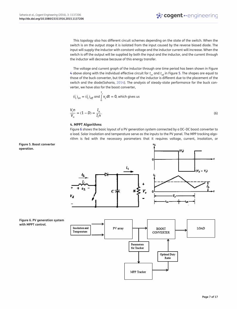
This topology also has different circuit schemes depending on the state of the switch. When the switch is on the output stage it is isolated from the input caused by the reverse biased diode. The input will supply the inductor with constant voltage and the inductor current will increase. When the switch is off the output will be supplied by both the input and the inductor, and the current through the inductor will decrease because of this energy transfer.
The voltage and current graph of the inductor through one time period has been shown in Figure 4 above along with the individual effective circuit for ton and toff in Figure 5. The shapes are equal to those of the buck converter, but the voltage of the inductor is different due to the placement of the switch and the diode(Saharia, 2014). The analysis of steady-state performance for the buck con-verter, we have also for the boost converter,
(iL)on = (iL)off and Ts
∫0
vLdt = 0, which gives us
4. MPPT AlgorithmsFigure 6 shows the basic layout of a PV generation system connected by a DC–DC boost converter to a load. Solar insolation and temperature serve as the inputs to the PV panel. The MPP tracking algo-rithm is fed with the necessary parameters that it requires voltage, current, insolation, or
(6)Vin
Vo= (1 − D) =
IoIin.
Figure 6. PV generation system with MPPT control.
Figure 5. Boost converter operation.
Page 8 of 17
Saharia et al., Cogent Engineering (2016), 3: 1137206http://dx.doi.org/10.1080/23311916.2015.1137206
temperature, and it sends a control signal in the form of duty ratio to operate the system at maxi-mum power point. Discussions on the three MPPT algorithms follow in the ensuing subsections:
4.1. Perturb and Observe MPPT AlgorithmThe most basic form of P&O algorithm compares the power previously delivered with the one after disturbance. If the comparison results such that the new power increases, the voltage is increased and vice versa. The P&O algorithm involves varying the voltage of the panel periodically with small incremental steps to reduce the oscillations around the MPP or a desired step. This algorithm is widely found to have been implemented with commercial system due to reduced circuitry and low number of depended parameters. There are four variations in voltage and the possible change in the resulting power as a reflection of the voltage change, which are tabulated in Table 2 (Esram & Chapman, 2007). The outcome of the perturbation is positive in the next step when the power change is positive, and negative in the reverse case.
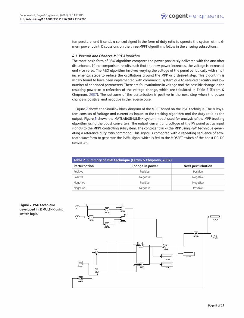
Figure 7 shows the Simulink block diagram of the MPPT based on the P&O technique. The subsys-tem consists of Voltage and current as inputs to the tracking algorithm and the duty ratio as the output. Figure 5 shows the MATLAB/SIMULINK system model used for analysis of the MPP tracking algorithm using the boost converters. The output current and voltage of the PV panel act as input signals to the MPPT controlling subsystem. The contoller tracks the MPP using P&O technique gener-ating a reference duty ratio command. This signal is compared with a repeating sequence of saw-tooth waveform to generate the PWM signal which is fed to the MOSFET switch of the boost DC–DC converter.
Table 2. Summary of P&O technique (Esram & Chapman, 2007)Perturbation Change in power Next perturbationPositive Positive Positive
Positive Negative Negative
Negative Positive Negative
Negative Negative Positive
Figure 7. P&O technique developed in SIMULINK using switch logic.

Page 9 of 17
Saharia et al., Cogent Engineering (2016), 3: 1137206http://dx.doi.org/10.1080/23311916.2015.1137206
4.2. Fuzzy Logic controlThe fuzzy logic and neural network-based controllers for MPPT involves the use of climatic data of insolation and temperature. Hence there needs to be an adequate knowledge of the behavior of the PV system connected to a dc load by a DC–DC converter working based on either fuzzy logic or neural network to generate the optimal duty ratio to extract maximum power from the system, for any given external atmospheric conditions.
Fuzzy logic-based design of MPPT controllers involves three components in its design. First the knowledge base of the designer, the fuzzification step, the inference diagram and the defuzzification process (Manas, 2015; Saleh et al., 2008). According to the input parameters of solar insolation and temperature, the output duty ratio corresponding to the MPP operation of a PV system, the designer must have knowledge of the relation between the input and output parameters. There must be sec-tional division of the solar insolation and temperature, as well as the output duty ratio.
Table 3. Control Rules for Fuzzy logic-based MPPTInsolation\temperature Duty ratio
Small Medium Large Very LargeSmall Small Small Small Medium
Medium Medium Medium Medium Large
Large Medium Large Very Large Very Large
Very Large medium Very Large Very Large Very Large
Figure 8. The membership functions of the fuzzy controller for insolation, temperature, and duty ratio.
Page 10 of 17
Saharia et al., Cogent Engineering (2016), 3: 1137206http://dx.doi.org/10.1080/23311916.2015.1137206
Solar radiation is divided into four fuzzy subset sections namely small, medium, large, and very large, covering insolation values between 0 and 1.2 kW/m2. The temperature values also have four sections of small, medium, large, and very large, membership functions ranging from 0 to 40 °C, simi-larly the duty ratio also has similar values of fuzzy subsets small, medium, large, and very large, membership function ranging from 0 to 0.75. The control relationship is tabulated in Table 3 as where the insolation and temperature serve as inputs and the duty ratio serves as the output for MPPT.
As shown in Figure 8, For the fuzzification step of the algorithm, the membership functions for solar insolation, temperature, and duty ratio are considered to be of symmetic triangular type. Based on the membership functions, a Mamdani based rule base is constructed having 4 × 4 = 16 rules. The rules aggregations are given by computing the minimum norm conjuction implication of fuzzy sub-set of the optimum duty ratio. As the rules are averaged, the defuzzification consists of use of the centrod method to get the duty ratio.
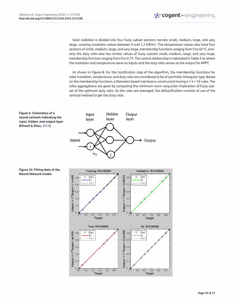
Figure 9. Schematics of a neural network indicating the input, hidden, and output layer (Eltawil & Zhao, 2013).
Figure 10. Fitting data of the Neural Network model.
Page 11 of 17
Saharia et al., Cogent Engineering (2016), 3: 1137206http://dx.doi.org/10.1080/23311916.2015.1137206
4.3. Neural NetworksNeural network-based controllers generally have three layers: input, the hidden and the output lay-ers as shown in Figure 9. The number of nodes (i – input node and j – hidden layer node) in each layer vary and are usually user dependent. Input variables are usually atmospheric parameters like solar insolation and temperature, or PV array paremeters like Voc and Isc or a combination of these paremeters. The output is generally one or several reference signal like duty ratio signal used to drive the DC–DC power converter interface to make it operate close to the MPP. The accuracy of the tack-ing algorithm based on neural network depends on the training algorithm used and the training of the network with data. As most of the PV panels have different characteristics, a neural network has to be specifically trained for the PV array with which it will be implemented. The PV array character-istics may change with time, and as such the neural network may need periodic tuning in the train-ing for a much robust and effective working (Esram & Chapman, 2007). In this study, neural network has been designed such that it takes solar insolation and temperature as the data inputs and pro-duces duty ratio corresponding to the input conditons as the output. The values of insolation have been varied in steps of 50 W/m2 from zero to 1200 kW/m2 and temperature in steps of 5 °C from zero to 40 °C. A total of 203 sets of input data were selected and the optimum duty ratio for each of the sets was calculated as shown in Figure 10. The neural network was then trained using these data-sets by backpropagation technique (Haykin, 1999).
5. Simulation Procedure and ResultsTo test the efficiency of tracking of the three algorithms mentioned above, they were modeled in simulation environment. The tracking factor that symbolizes the effectiveness of the tracking algo-rithm is given by the relation:
Where η is the tracking factor, Pinst is the instantaneous power at the operating point of the PV mod-ule, and Pmpp is the instantaneous MPP of the PV module under given condition of insolation and temperature.
The MATLAB/SIMULINK software platform was used for modeling and implementation of the algo-rithms. There were two scenarios considered, one in which the temperature was kept constant and
(7)� =Pinst
Pmpp
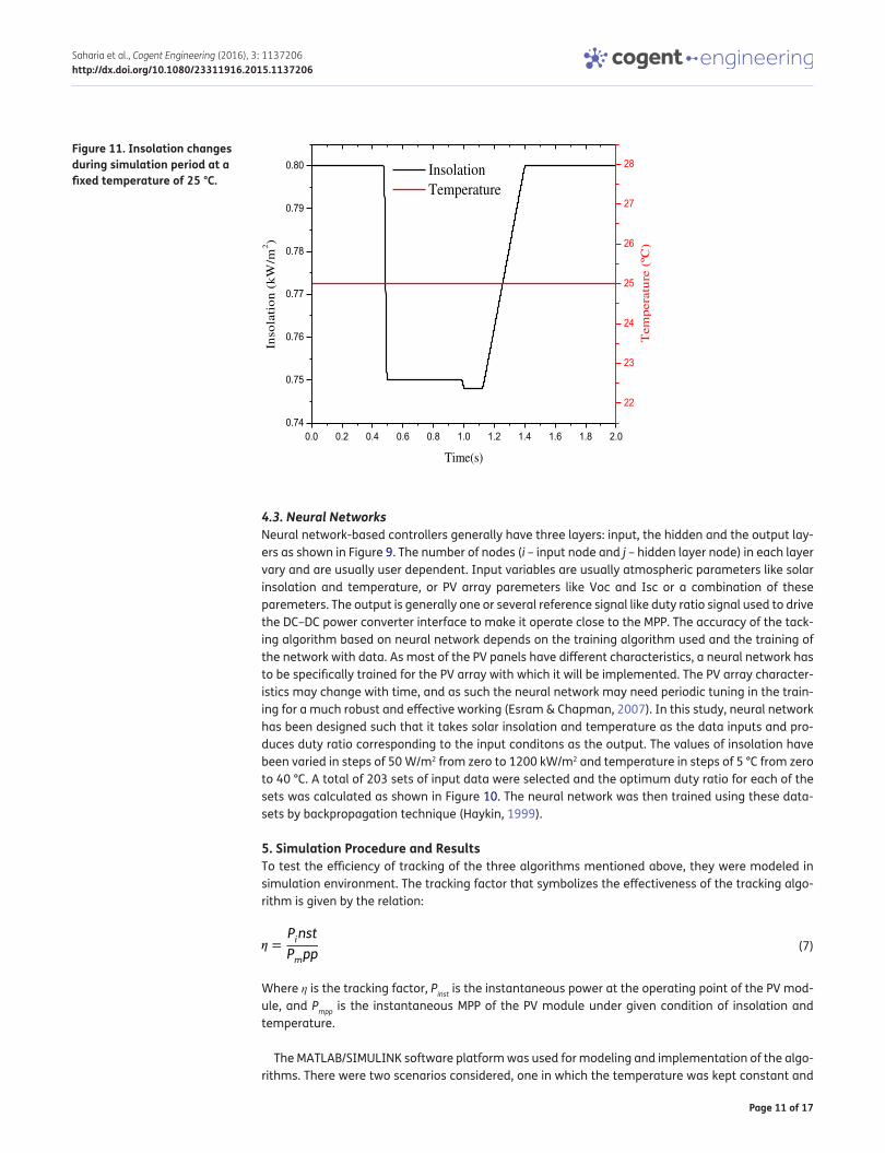
Figure 11. Insolation changes during simulation period at a fixed temperature of 25 °C.
0.0 0.2 0.4 0.6 0.8 1.0 1.2 1.4 1.6 1.8 2.00.74
0.75
0.76
0.77
0.78
0.79
0.80 Insolation Temperature
Time(s)
Inso
lati
on
(k
W/m
2)
22
23
24
25
26
27
28
Tem
per
atu
re (
ºC)
Page 12 of 17
Saharia et al., Cogent Engineering (2016), 3: 1137206http://dx.doi.org/10.1080/23311916.2015.1137206
the insolation on the PV panel was changed. Next to ascertain the response of the algorithms to change in temperature, the insolation was fixed and a varying temperature was given as the input. The two cases and the behavior of the three algorithms tracking ability for a set of external condi-tions are detailed in the following sections:
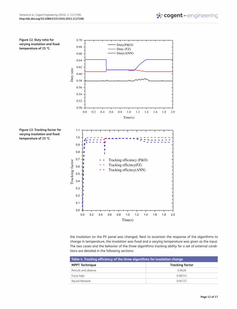
Figure 12. Duty ratio for varying insolation and fixed temperature of 25 °C.
0.0 0.2 0.4 0.6 0.8 1.0 1.2 1.4 1.6 1.8 2.00.50
0.52
0.54
0.56
0.58
0.60
0.62
0.64
0.66
0.68
0.70
Dut
y ra
tio
Time(s)
Duty(P&O)Duty (FZ)Duty(ANN)
Figure 13. Tracking factor for varying insolation and fixed temperature of 25 °C.
0.0 0.2 0.4 0.6 0.8 1.0 1.2 1.4 1.6 1.8 2.00.0
0.1
0.2
0.3
0.4
0.5
0.6
0.7
0.8
0.9
1.0
1.1
Tra
ckin
g f
acto
r
Time(s)
Tracking efficiency (P&O)Tracking efficincy(FZ)Tracking efficincy(ANN)
Table 4. Tracking efficiency of the three algorithms for insolation changeMPPT Technique Tracking factorPerturb and observe 0.9628
Fuzzy logic 0.98252
Neural Network 0.94737
Page 13 of 17
Saharia et al., Cogent Engineering (2016), 3: 1137206http://dx.doi.org/10.1080/23311916.2015.1137206
5.1. Case I: Tracking Response to Step and Linear Change in Insolation at Fixed TemperatureIn the first scenario, to evaluate the three tracking algorithms, we exposed the PV model to a solar ra-diation of 800 W/m2 at a fixed temperature of 25 °C to start with. The temperature values remain fixed for the simulation interval. The isolation takes a step change from 800 to 750 W/m2 at 0.49 s. It remains fixed at this value of radiation till 1.05 s, when it slightly decreases and at 1.125 s starts to rise linearly and reaches a value of 800 W/m2 at 1.4 s and holds this value up to the end of simulation time of 2 s.
The variation in duty ratio as a result of the individual tracking algorithms to attain MPP operation is shown in figure. It is observed that the highest fluctuation in the duty ratio takes place for the neural network-controlled tracker indicating that it is the most sensitive of the three algorithms. The fuzzy logic-controlled duty ratio and P&O duty ratio are much more stable and their variation due to the fluctuation in the insolation change indicates a stable system in the dynamic sense.
From the point of view of tracking efficiency of the three algorithms, we observe that the fuzzy controller is most effective in tracking the MPP for the change in solar insolation, followed closely by the P&O algorithm evaluated as per Eq. (12). The neural network algorithm is seen to be having the least efficient tracking. The convergence speeds of the algorithms also vary. The fuzzy logic control-ler is seen to achieve tracking efficiency fastest as shown in Figure 12 and Figure 13. This is closely followed by P&O technique and the neural network-based MPPT algorithm. The average tracking efficiency for the three algorithms is tabulated in Table 4.
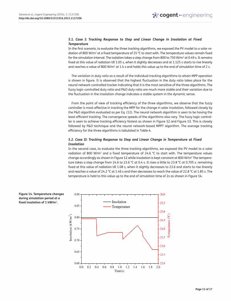
5.2. Case II: Tracking Response to Step and Linear Change in Temperature at Fixed InsolationIn the second case, to evaluate the three tracking algorithms, we exposed the PV model to a solar radiation of 800 W/m2 and a fixed temperature of 24.6 °C to start with. The temperature values change accordingly as shown in Figure 12 while insolation is kept constant at 800 W/m2 The tempera-ture takes a step change from 24.6 to 23.6 °C at 0.4 s. It rises a little to 23.8 °C at 0.705 s. remaining fixed at this value of radiation till 1.08 s, when it slightly decreases to 23.6 and starts to rise linearly and reaches a value of 24.2 °C at 1.46 s and then decreases to reach the value of 22.8 °C at 1.85 s. The temperature is held to this value up to the end of simulation time of 2s as shown in Figure 14.
Figure 14. Temperature changes during simulation period at a fixed insolation of 1 kW/m2.
0.0 0.2 0.4 0.6 0.8 1.0 1.2 1.4 1.6 1.8 2.00.60
0.65
0.70
0.75
0.80
0.85
0.90
Time(s)
Inso
lati
on
(k
W/m
2)
22.0
22.5
23.0
23.5
24.0
24.5
25.0
25.5
26.0
Insolation Temperature
Tem
per
atu
re (
ºC)
Page 14 of 17
Saharia et al., Cogent Engineering (2016), 3: 1137206http://dx.doi.org/10.1080/23311916.2015.1137206
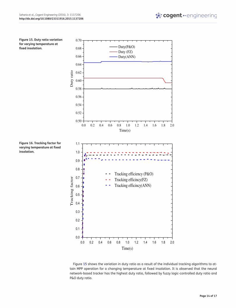
Figure 15 shows the variation in duty ratio as a result of the individual tracking algorithms to at-tain MPP operation for a changing temperature at fixed insolation. It is observed that the neural network-based tracker has the highest duty ratio, followed by fuzzy logic-controlled duty ratio and P&O duty ratio.
Figure 15. Duty ratio variation for varying temperature at fixed insolation.
0.0 0.2 0.4 0.6 0.8 1.0 1.2 1.4 1.6 1.8 2.00.50
0.52
0.54
0.56
0.58
0.60
0.62
0.64
0.66
0.68
0.70
Time(s)
Duty(P&O)Duty (FZ)Duty(ANN)
Du
ty r
atio
Figure 16. Tracking factor for varying temperature at fixed insolation.
0.0 0.2 0.4 0.6 0.8 1.0 1.2 1.4 1.6 1.8 2.00.0
0.1
0.2
0.3
0.4
0.5
0.6
0.7
0.8
0.9
1.0
1.1
Time(s)
Tracking efficiency (P&O)Tracking efficincy(FZ)Tracking efficincy(ANN)
Tra
ck
ing
facto
r

Page 15 of 17
Saharia et al., Cogent Engineering (2016), 3: 1137206http://dx.doi.org/10.1080/23311916.2015.1137206
From the point of view of tracking efficiency of the three algorithms, we observe that the fuzzy con-troller is most effective in tracking the MPP for the change in temperature, followed closely by the P&O algorithm as shown in Figure 16 and Table 5. The neural network algorithm is seen to be having the least efficient tracking, similar to case I where the results are also in the same corresponding order.
The speed of convergence at the perturbation is also seen to vary with fuzzy logic controller that converges the fastest. This is followed closely by P&O technique and the neural network-based tracking algorithm. The average tracking efficiency of the three algorithms to the change in tem-perature is recorded in Table 5.
6. DiscussionTable 6 shows a comparative analysis of the three algorithms. The comparison is made on the basis of the speed of response of the algorithm to the change in external perturbation due to variation in the environmental conditions, change of duty ratio and the tracking efficiency. The fast change in response to the change of weather parameters namely insolation and temperature indicates the high sensitivity to external perturbations. This also indicates that an algorithm is able to respond quickly, which is a sought after quality of the MPPT algorithm to make it implementable in systems where fast and swift varying controller response is a desired requirement. The degree fluctuations in duty ratio indicate that the algorithm is unstable at the equilibrium, which causes the converter to oscillate thereby causing reduced efficiency due to system losses. Therefore a stable and low chang-ing algorithm with reduced oscillations at steady state is a sought after characteristic in such algo-rithms. From Table 6 it is seen that the fuzzy logic-based controller leads the other two techniques in this regard and emerges as the best algorithm for tracking of PV systems.
7. ConclusionIn view of the unavailability of a common bench test on the three most commonly used tracking al-gorithms, this paper presents a common simulation platform for testing and assessment of P&O,
Table 6. Comparison among the tracking algorithmsAlgorithm Case I Case II
Speed of response to external perturbation
Change of duty ratio
Tracking efficiency
Speed of response to external perturbation
Change of duty ratio
Tracking efficiency
Fuzzy logic Fastest Stable and low change
Highest Fastest Lower than neural network
Highest
Neural net-work
Slower than P&O Highest change
Least efficient Slower than P&O Highest value of duty ratio
Least efficient
Perturb and observe
Fast Fluctua-tion is less compared to neural networks
Lower than fuzzy logic
Fast Fluctuation is less compared to neural networks
Lower than fuzzy logic
Table 5. Tracking efficiency of the three algorithms for temperature changeMPPT Technique Tracking factorPerturb and observe 0.95603
Fuzzy logic 0.98645
Neural Network 0.90655

Page 16 of 17
Saharia et al., Cogent Engineering (2016), 3: 1137206http://dx.doi.org/10.1080/23311916.2015.1137206
fuzzy logic, and neural network-based tracking algorithms. The biggest hindrance for implementation of a neural network-based tracking algorithm is the training requirement. For P&O technique, the re-sults are optimal only if there is a proper knowledge of the range of duty ratio variation for a system, corresponding to the changes in the atmospheric conditions. From the simulation results, it is ob-served that the tracking effectiveness decreases in the order fuzzy logic controller, P&O algorithm, and neural network-based tracking. The results stand for changing insolation at fixed temperature as well as for a change in temperature at a constant insolation level. The fuzzy logic control is better suited for tracking as it gives the highest performance for the changes in the external conditions. From the view point of convergence speed as well, the fuzzy logic controller performs the best among the three techniques achieving a stable state after a change in either the insolation profile or the temperature change. The results can be used as a reference for implementation of fuzzy logic MPP trackers in hardware making use of digital signal processor controller (DSP) or field programmable gate array (FPGA). Moreover possible application of hybrid algorithms like Genetic algorithm (GA) -Fuzzy, Particle swarm optimization (PSO)-Fuzzy, Differential Evolution (DE) -Fuzzy logic-based MPPT controllers can also be investigated to check for better response in the overall system performance.
FundingThe authors received no direct funding for this research.
Author detailsBarnam Jyoti Saharia1
E-mail: [email protected] Manas1
E-mail: [email protected] Kanta Talukdar2
E-mail: [email protected] Department of Electronics and Communication Engineering,
Tezpur University, Assam 784028, India.2 Department of Electrical Engineering, Assam Engineering
College, Assam 781013, India.
Citation informationCite this article as: Comparative evaluation of photovoltaic MPP trackers: A simulated approach, Barnam Jyoti Saharia, Munish Manas & Bani Kanta Talukdar, Cogent Engineering (2016), 3: 1137206.
ReferencesAhmed, N. A., & Miyatake, M. (2008). A novel maximum power
point tracking for photovoltaic applications under partially shaded insolation conditions. Electric Power Systems Research, 78, 777–784. http://dx.doi.org/10.1016/j.epsr.2007.05.026
Chih-Lyang, H., Li-Jui, C., & Yuan-Sheng, Y. (2007). Network-based fuzzy decentralized sliding-mode control for car like mobile robots. IEEE Transactions on Industrial Electronics, 54, 574–585.
Eltawil, M. A., & Zhao, Z. (2013). MPPT techniques for photovoltaic applications. Renewable and Sustainable Energy Reviews, 25, 793–813. http://dx.doi.org/10.1016/j.rser.2013.05.022
Esram, T., & Chapman, P. L. (2007). Comparison of photovoltaic array maximum power point tracking techniques. IEEE Transactions on Energy Conversion, 22, 439–449.
Fathabadi, H. (2015). Lambert W function-based technique for tracking the maximum power point of PV modules connected in various configurations. Renewable Energy, 74, 214–226. http://dx.doi.org/10.1016/j.renene.2014.07.059
Haykin, S. (1999). Neural Networks A Comprehensive Foundation (2nd ed.). Pearson Education.
Hohm, D. P., & Ropp, M. E. (2003). Comparative study of maximum power point tracking algorithms. Progress in Photovoltaics: Research and Applications, 11, 47–62. doi:10.1002/pip.459
Iqbal, A., Ahmed, S. K. M., Abu-Rub, H., & Sinan, S. (2010). Adaptive neuro-fuzzy inference system based maximum power point tracking of a solar PV module. 2010 IEEE International Energy Conference & Exhibition, Energycon (pp. 51–56). Manama. doi:10.1109/ENERGYCON.2010.5771737
Jain, S., & Agarwal, V. (2007). New current control based MPPT technique for single stage grid connected PV systems. Energy Conversion and Management, 48, 625–644. http://dx.doi.org/10.1016/j.enconman.2006.05.018
Kim, S. (2007). Robust maximum power point tracker using sliding mode controller for the three- phase-grid connected photovoltaic system. Solar Energy, 81, 405–414. http://dx.doi.org/10.1016/j.solener.2006.04.005
Kottas, T. L., Boutalis, Y. S., & Karlis, A. D. (2006). New maximum power point tracker for PV arrays using fuzzy controller in Close cooperation with fuzzy cognitive networks. IEEE Transactions on Energy Conversion, 21, 793–803. doi:10.1109/TEC.2006.875430
Kyocera KC120-1 multi-crystalline photovoltaic module datasheet. (2001). Retrieved September 1, 2015 from (www.kyocerasolar.com/assets/001/5180.pdf
Larbes, C., Cheikh, S. M. A., Obeidi, T., & Zerguerras, A. (2009). Genetic algorithms optimized fuzzy logic control for the maximum power point tracking in photovoltaic system. Renewable Energy, 34, 2093–2100. http://dx.doi.org/10.1016/j.renene.2009.01.006
Li, S. (2015). A maximum power point tracking method with variable weather parameters based on input resistance for photovoltaic system. Energy Conversion and Management, 106, 290–299.
Liu, X., & Lopes, L. A. C. (2004). An improved perturbation and observation maximum power point tracking algorithm for PV arrays. Power electronics specialists conference, 2004, IEEE 35th annual Power electronics specialist conference 2004, PESC 04 (pp. 2005–2010).
Liu, L., Liu, C., & Gao, H. (2013). A novel improved particle swarm optimization maximum power point tracking control method for photovoltaic array by using current calculated predicted arithmetic under partially shaded conditions. Journal of Renewable and Sustainable Energy, 5. doi:10.1063/1.4858615
Manas, M.. (2015, February 13–14). Development of self-sustainable technologies for smart grid in India. 2015 IEEE International Conference on Computational Intelligence & Communication Technology (CICT) (pp. 563–568).
Manas, M., Zaheeruddin, M., & Sharma, B. B. (2015, March 3–4). Development of a benchmark for the interpretation of

Page 17 of 17
Saharia et al., Cogent Engineering (2016), 3: 1137206http://dx.doi.org/10.1080/23311916.2015.1137206
transformer frequency response analysis results. 2015 International Conference on Cognitive Computing and Information Processing (CCIP) (pp. 1–5).
de Medeiros Torres, A., Antunes, F. L. M., & dos Reis, F. S.. (1998). An artificial neural network-based real time maximum power tracking controller for connecting a PV system to the grid. Proceeding of IEEE the 24th annual conference on industrial electronics society (Vol. 1, pp 554–558. Aachen. doi:10.1109/IECON.1998.724303
Mellit, A., & Kalogirou, S. A. (2008). Artificial intelligence techniques for photovoltaic applications: A review. Progress in Energy and Combustion Science, 34, 574–632. doi:10.1016/j.pecs.2008.01.001
Mellit, A., Kalogirou, S. A., Hontoria, L., & Shaari, S. (2008). Artificial intelligence techniques for sizing photovoltaic systems: A review. Renewable and Sustainable Energy Reviews, 13, 406–419. doi:10.1016/j.rser.2008.01.00
Muralidhar, K. & Susovon, S. (2015). Modified perturb and observe MPPT algorithm for drift avoidance in photovoltaic systems. IEEE Transactions On Industrial Electronics, 62, 5549–5559.
Saharia, B. J. (2014). A theoretical study of performance and design constraints of non-isolated Dc–Dc converters. International Journal Of Innovative Research In Electrical, Electronics, Instrumentation And Control Engineering, 2, 1920–1925.
Salah, C. B., & Ouali, M. (2011). Comparison of fuzzy logic and neural network in maximum power point tracker for PV systems. Electric Power Systems Research, 81, 43–50.
Saleh, C. B., Chaaben, M., & Ammar, M. B. (2008). Multi-criteria fuzzy algorithm for energy management of a domestic photovoltaic panel. Renewable Energy, 33, 993–1001. http://dx.doi.org/10.1016/j.renene.2007.05.036
Sher, H. A., Murtaza, A. F., Noman, A., Addoweesh, K. E., Al-Haddad, K., & Chiaberge, M. (2015). A New sensorless hybrid MPPT algorithm based on fractional short-circuit current measurement and P&O MPPT. IEEE Transactions on Sustainable Energy, 6, 1426–1434.
Sivasubramaniam, S., Faramus, A., Tilley, R. D., & Alkaisi, M. M. (2014). Performance enhancement in silicon solar cell by inverted nanopyramid texturing and silicon quantum dots coating. Journal of Renewable and Sustainable Energy, 6. doi:10.1063/1.4828364
Subhadeep, B., & Saharia, B. J. (2014). A comparative study on converter topologies for maximum power point tracking application in photovoltaic generation. Journal of Renewable and Sustainable Energy, 6, 053140. doi:10.1063/1.4900579
Tsang, K. M., & Chan, W. L. (2015). Maximum power point tracking for PV systems under partial shading conditions using current sweeping. Energy Conversion and Management, 93, 249–258. http://dx.doi.org/10.1016/j.enconman.2015.01.029
Venelinov, T. A., Leonardo, C. G., Vincenzo, G., Francesco, C., & Okyay, K. (2007). Sliding mode neuro-adaptive control of electrical drives. IEEE Transactions on Industrial Electronics, 54, 671–679.
Zaheeruddin, & Manas, M. (2015a). Analysis of Design of technologies, tariff Structures and regulatory policies for sustainable growth of the Smart grid. Energy Technology and Policy Journal, 2, 28–38.
Zaheeruddin, & Manas, M.. (2015b). A new approach for the design and development of renewable energy management system through microgrid central controller. Energy Reports, 1, 156–163). Elsevier. http://dx.doi.org/10.1016/j.egyr.2015.06.003
© 2016 The Author(s). This open access article is distributed under a Creative Commons Attribution (CC-BY) 4.0 license.You are free to: Share — copy and redistribute the material in any medium or format Adapt — remix, transform, and build upon the material for any purpose, even commercially.The licensor cannot revoke these freedoms as long as you follow the license terms.
Under the following terms:Attribution — You must give appropriate credit, provide a link to the license, and indicate if changes were made. You may do so in any reasonable manner, but not in any way that suggests the licensor endorses you or your use. No additional restrictions You may not apply legal terms or technological measures that legally restrict others from doing anything the license permits.
Cogent Engineering (ISSN: 2331-1916) is published by Cogent OA, part of Taylor & Francis Group. Publishing with Cogent OA ensures:• Immediate, universal access to your article on publication• High visibility and discoverability via the Cogent OA website as well as Taylor & Francis Online• Download and citation statistics for your article• Rapid online publication• Input from, and dialog with, expert editors and editorial boards• Retention of full copyright of your article• Guaranteed legacy preservation of your article• Discounts and waivers for authors in developing regionsSubmit your manuscript to a Cogent OA journal at www.CogentOA.com