Embed Size (px)
Citation preview

International Journal on Electrical Engineering and Informatics - Volume 9, Number 4, December 2017
Comparative Power Quality analysis of Conventional and Modified
DSTATCOM Topology
Pradeep Kumar
NIT Sikkim, Ravangala 737139 INDIA
Abstract: In this paper, the two topologies of Distribution Static Compensator
(DSTATCOM) such as conventional DSTATCOM and modified DSTATCOM with
their performances are investigated in terms of power quality improvement. Normally
the DSTATCOM has shunt voltage source inverter (VSI) connected to point of common
coupling (PCC) through the interfacing inductor. It is possible to modify DSTATCOM
by connecting a capacitor in series with the interface inductor at the point of common
coupling. This Modified topology requires a lower value of dc link voltage across the dc
storage capacitor of voltage source inverter (VSI) for compensation of source currents,
when compared with the conventional DSTATCOM topology. The reference signal for
PWM generator is generated using synchronous reference frame theory and Indirect PI
theory. A detailed simulation study to compare the performances of conventional and
modified topologies are carried out using MATLAB 7.1 and the superior features of
modified DSTATCOM topology are established.
Keywords: Distribution static compensator (DSTATCOM), Indirect PI (IPI) controller,
Point of common coupling (PCC), Synchronous reference frame (SRF) controller,
Voltage-source inverter (VSI).
1. Introduction
Three-phase power systems are facing severe power quality problems such as poor voltage
regulation, large reactive power burden, harmonics current, and load unbalancing. The power
quality problems and their improvement techniques are reported in the literature over the years
[1-8]. The Distribution Static Compensator (DSTATCOM) is one of the power quality
improvement device which is used to provide reactive power for improving voltage regulation,
to reduce harmonics in the source currents, and to balance the supply currents when the loads
are unbalanced and nonlinear. There are various topological structures of the DSTATCOM are
reported in the literature such as a voltage source converter (VSC) with four legs [9], three
single-phase VSC [8], three-leg VSC with split capacitors[9], and three-leg VSC with a zig-zag
transformer [10]. To generate reference signal for PWM generator in order to provide pulses
for the control of VSI of DSTATCOM, many control techniques are presented in the literature,
viz., instantaneous reactive power theory (p−q theory), synchronous reference frame theory,
power balance theory, etc. [6,8,9]. Many soft computing based control algorithms such as
neural network, fuzzy logic and adaptive neuro-fuzzy etc [11-14], have been also adopted for
the control of VSI based DSTATCOM.
Due to less computation time and easily availability of input variable, Indirect PI and
synchronous reference frame theory based control algorithms are implemented in three phase
shunt connected DSTATCOM for compensation of unbalanced and nonlinear loads.
This paper deals with the comparative performance analysis of conventional and modified
DSTATCOM topology for three phase four wire systems. This modified topology requires
lesser value of dc link voltage when compared with existing conventional topology.
The paper is organized as follows. After starting with Introduction in section 1, section 2
briefly presents about the DSTATCOM topology in terms of conventional and modified
approach. Section 3 gives a detailed description of control signals for generation of reference
signals for VSI valves. Section 4 describes about simulation results for the conventional and
Received: November 4th, 2017. Accepted: December 29th, 2017
DOI: 10.15676/ijeei.2017.9.4.11
786

modified DSTATCOM topologies and finally section 5 represents conclusion of this research
work.
2. DSTATCOM Topology
Distribution static compensator (DSTATCOM) is just like as a shunt active filter which is
attached in parallel to the load and source at PCC. Here the DSTATCOM Topology is
categorized in terms of conventional and modified DSTATCOM topology as follows:
A. Conventional DSTATCOM Topology
Single line diagram of conventional DSTATCOM topology is shown in Figure1.
Conventional topology has VSI which is coupled in parallel to the load at the PCC through
interface inductor (Lf ). The main task of the interface inductor is for proper shaping of the
filter currents while tracking the reference filter currents. The capacitance Cdc is the dc storage
capacitor used for maintaining the input voltage of VSI at reference value of Vdcref . However,
the voltage across Cdc is instantaneously varying quantity and is denoted as vdc.
Figure 1. Conventional DSTATCOM
Design of DC Capacitor (Cdc)
In order to drive the compensated currents, the value of Vdcref should to be 1.6 times the
peak value of system line voltage (Vlm) as given in [15-17]. Once the value of Vdcref is
selected, the value of Cdc can be determined from the transient period in the system and its
ability to regulate under this condition. Consider the STATCOM is connected to an x kVA
system and deals with 0.5x kVA and 1.5x kVA handling capability under transient conditions
for ’p’ cycles. The energy in x kVA system in joules is x X 1000 joules. An increase in system
kVA load results a decrease in vdc during transient and vice versa. Allowing a maximum of
12.5% variation in vdc during transients, the differential energy (Ec) across Cdc1 (for increase
in load) is given as
2
4.16.122
1 lmlmdcC
VVCE
(1)
The change in system energy (Es) for load change from x kVA to 1.5x kVA in joules is
Es = (1.5x−x) 1000 p T (2)
Where, T is the time period of system voltage and ′p′ is the period of transient. Therefore
from equations
1 and 2, Cdc1 is given as
221
4.16.1
10005.12
lmlm
dcVV
pTxxC
(3)
Pradeep Kumar
787

Similarly,Cdc2 is calculated for the case of decrease in load from x kVA to 0.5x kVA, where
vdc is allowed to increase up to 1.8Vlm from a reference value of 1.6Vlm. The maximum of the
obtained Cdc1, Cdc2 values is chosen as the dc storage capacitor Cdc.
B. Modified DSTATCOM Topology
The basic difference between conventional and modified topologies is the insertion of
capacitor Cf which is connected in series with the interface inductor Lf as shown in Figure 2.
Since Cf is incorporated in between STATCOM and PCC, the voltage build up across Cf plays
a vital role for calculating the value of reference dc link voltage required for compensation in
modified topology.
Figure 2. Modified DSTATCOM
Design of Series Capacitor (Cf )
Let the dc link voltage required for compensation in modified topology and conventional
topology is denoted as Vdcmref and Vdcref respectively, Ifmax1 represent the maximum value of
fundamental filter current corresponding to the phase where reference filter current is
maximum [17]. The VA rating of the PWM voltage source inverter (active filter) used in
conventional topology is denoted as VAc−AF (here the subscript ’c’ stands for conventional and
’AF’ for active filter) and is given below in (4).
222
33
1maxfdcref
AFc
IVVA (4)
The rating of the active filter with Vdcmref as the input dc link voltage in modified topology,
is represented as VAm−AF (here the subscript ’m’ stands for modified) and is given below in (5).
222
33
1maxfdcmref
AFm
IVVA (5)
The difference in (4) and (5) should be equal to the VA rating the series combination of the
passive elements interface inductor and series capacitor in order to have proper compensation.
Therefore,
2
1max
2)(3
f
LCAFmAFc
IXXVAVA (6)
Where, XC = 1/(2πfCf ), XL = (2πfLf ) represents the reactance’s of Cf and Lf respectively.
Therefore from equations (4), (5) and (6), 1/Cf can be determined as given below in (7), where
ω = 2π f and the corresponding fundamental component of rms voltage (vc f rms1) developed
across Cf , is given in (8).
f
f
dcmrefdcref
f LI
VVC 2
1max2
)(1
(7)
f
f
cfrms fCI
V 21)2
(1max
1 (8)
Comparative Power Quality analysis of Conventional and Modified
788

3. Generation of Reference Signals
Generation of reference signals for the PWM generator of VSI based DSTATCOM is
achieved by Indirect PI [18] and synchronous reference frame control techniques [8, 19]. The
detail explanation of these control techniques have been given below:
A. Indirect PI controller
An error signal is obtained by comparing the reference voltage (set voltage) and the
terminal voltage (rms value). This error is processed to a PI controller. The output of PI
controller is the angle δ. Figure 3 represents Indirect PI controller which generates angle δ.
Figure 3. Indirect PI controller
From the angle δ, three phase sinusoidal signal Vcontrol is obtained as follows:
A
B
C
V Sin( t )
V Sin( t 2 / 3)
V Sin( t 2 / 3)
(9)
Three phase voltage signal VA,VB and VC are shifted by 0° ,120° and 240° respectively.
Figure 4 represents phase modulation of control angle δ. Sinusoidal signal Vcontrol is fed to
PWM signal generator in order to generate switching pulses for IGBT switches of the voltage
source inverter valves. Figure 5 shows simulink model of DSTATCOM controller which
consist sequence analyzer, discrete PI controller and phase modulation block to generate
voltage signal for the PWM generator.
Figure 4. Phase Modulation of the control angle δ
Figure 5. Simulink model of DSTATCOM controller
Pradeep Kumar
789

B. Synchronous Reference Frame Controller
Figure 6 depicts step by step procedure for obtaining reference value of three phase
compensator current from the three phase load current. The load currents from the a–b–c frame
are first converted to the α–β frame and then to the d–q frame using the following formulation
La
Ld
Lb
Lq
Lc
i2 2cos t cos t cos ti 3 32 i3i 2 2sin t sin t sin t i3 3
(10)
Ld Ld
LqLq
i iG(s)
ii
(11)
Here the DC voltage controller is designed as a proportional controller. The PCC voltage
controller is designed as a PI controller. The output of the proportional (P) controller at the dc
bus voltage of DSTATCOM is considered as the current iCd and The output of the
proportional-integral (PI) controller at the PCC bus voltage of DSTATCOM is considered as
the current iCq . u is a logical variable equal to (a) zero if PF is to be regulated (b) one if bus
voltage is to be regulated. 1qK in latter case.
When PF is to be controlled, qK is determined by required power factor as follows
*
sq
L
QK
Q
(12)
Where *
SQ reference reactive power supplied by source (at PCC) and LQ is average
reactive power defined by L t LqQ V i
(13)
For unity power factor, cos 1, so 0
*
SQ VIsin 0 hence qK 0
Figure 6. Synchronous Reference Frame control scheme
The desired source currents (in d-q component) are obtained as
*
Sd Ld Cdi i i ,
*
Sq q Lq Cqi K i ui (14)
The reference for the source current in the d-q frame are first converted to the α–β frame
and then to the a-b-c frame using the following formulation
Comparative Power Quality analysis of Conventional and Modified
790

*
sa
*
sb
*
sc
cos t sin ti
2 22i cos t sin t3 3 3
i2 2cos t sin t
3 3
*
sd
*
sq
i
i
(15)
The desired compensator currents (iCa*,iCb
*,iCc*) are obtained as
* *
Ca La Sai i i ,
* *
Cb Lb Sbi i i ,
* *
Cc Lc Sci i i
4. Simulation results and analysis
The models of the conventional and modified DSTATCOM topologies shown in Figure 1,
Figure 2 respectively were build in MATLAB 7.1 simulation package and its sim power
toolboxes to carry out simulation studies. The system parameters for the simulation are given
in Table 1. The main intention in this simulation is to show two different performance aspects
for both the conventional and modified DSTATCOM topologies: 1) Source current harmonic
reduction and power factor Improvement under Indirect PI control; 2) Source current harmonic
reduction and power factor Improvement under synchronous reference frame control. The total
harmonic distortion (THD) measurements of source current are compared for Indirect PI and
synchronous reference frame controls under both topologies and verified by the limits specified
by the IEEE519 and IEC61000-3 harmonic standards [20].
Table 1. System Parameters for simulation
Parameter Values
System Voltages (Three-phase) with
frequency
VL-L (rms) = 400 V , 50 Hz
Feeder (Source) impedance Zs = 1+ j0.628 Ὠ
Linear (Unbalanced) load Zla = 22+ j6.28 Ω, Zlb = 35+ j18.84 Ω,
Zlc = 70+ j37.69 Ω
Nonlinear load(Three phase diode with R-
L load)
RD = 80 Ω, LD = 400 mH
Power converter IGBTs/diodes
PWM switching frequency 10 kHz
Inverter (VSI) parameters Cdc = 1000μF, Lf = 20 mH, Rf = 0.1 Ω
DC link voltage (DC side of Inverter) Conventional topology (Vdcref = 1.6Vml = 900
V)
Modified topology(Vdcmref = Vml =
560 V)
Gains for the PI controller Conventional topology (Kp = 10, Ki = 0.1),
Modified topology (Kp = 1, Ki = 0.01)
Gains for the proportional controller Conventional and modified topology (Kp =
0.6)
Series capacitor (Series with interface
inductor)
Modified topology (Cf = 100 μF )
Pradeep Kumar
791

A. Source current harmonic reduction and power factor Improvement under Indirect PI
control
In this section, the voltage and current characteristic of the conventional and modified
DSTATCOM systems in terms of harmonic compensation in source current and power factor
improvement on source side are illustrated. Firstly the performance characteristic of the
conventional DSTATCOM system is tested under Indirect PI control technique. Figure 7
depicts voltage and current waveform for Conventional DSTATCOM in Without DSTATCOM
and With DSTATCOM condition.
(a) (b)
Figure 7. Voltage and current waveform for Conventional DSTATCOM
(a)Without DSTATCOM (b) With DSTATCOM
In case of Without DSTATCOM, there is no compensation i.e. compensation current is
zero. The load current and source current waveform is exactly same and is non-sinusoidal in
nature due to non-linear load at the PCC. The waveform of terminal voltage is sinusoidal. A
low value of DC link voltage (2V) appears across DC capacitor. But when the DSTATCOM is
put in operation with the distribution system, Compensation occurs i.e. compensation current is
non-zero value. Load current is unbalanced and non-linear but source current is pure sinusoidal
and in phase with terminal voltage which is also sinusoidal nature. Hence power factor will be
improved to unity when DSTATCOM is connected to the distribution system. DC link voltage
across DC capacitor is 70 V approximately which is large from previous case. Figure 8
indicates THD spectrum of source current for conventional DSTATCOM under Indirect PI
control by considering without and with DSTATCOM. Without DSTATCOM source current
THD is 11.13% but when the DSTATCOM is switched on, the THD is reduced to 2.72%.
Comparative Power Quality analysis of Conventional and Modified
792

(a) (b)
Figure 8. THD spectrum of source current for conventional DSTATCOM
(a)Without DSTATCOM (b) With DSTATCOM
(a) (b)
Figure 9. Voltage and current waveform for Modified DSTATCOM
(a)Without DSTATCOM (b) With DSTATCOM
Pradeep Kumar
793

Now the performance characteristic of the Modified DSTATCOM system is tested under
Indirect PI control technique. Figure 9 indicates various voltage and current waveform for
Modified DSTATCOM in without and with DSTATCOM condition.
In this topology before compensation, compensation current is zero. Both source current
and load current are unbalanced and non-linear. Terminal voltage is sinusoidal with a
magnitude of 300V. DC link voltage is varying from 40V to 30V. But after compensation,
compensation current occurs and its value is 13A. Load current remains unbalanced and non-
sinusoidal. However source current and terminal voltages have different magnitude but both
are in phase which depicts power factor improvement on supply side. A small variation of DC
link voltage occurs from 50V to 40V. Figure 10 represents THD spectrum of source current
for Modified DSTATCOM topology under Indirect PI control. THD of source current is
reduced from 11.13% without DSTATCOM to 2.36% with DSTATCOM.
(a) (b)
Figure 10. THD spectrum of source current for Modified DSTATCOM
(a)Without DSTATCOM (b) With DSTATCOM
B. Source current harmonic reduction and power factor Improvement under synchronous
reference frame control
Synchronous reference frame control technique is adopted for conventional and modified
DSTATCOM systems in order to test source current harmonic compensation and power factor
improvement on supply side. Initially, performance of conventional DSTATCOM topology
will be discussed. Figure 11 indicates various current and voltage waveform for the
conventional DSTATCOM topology under synchronous reference frame control.
Comparative Power Quality analysis of Conventional and Modified
794

(a) (b)
Figure 11. Voltage and current waveform for conventional DSTATCOM
(a)Without DSTATCOM (b) With DSTATCOM
(a) (b)
Figure 12. THD spectrum of source current for conventional DSTATCOM
(a)Without DSTATCOM (b) With DSTATCOM
Pradeep Kumar
795

Before switching of the DSTATCOM with the distribution system, the compensation
current is approximately zero. Unbalanced and non-linear load create load current and source
current waveform equal but non-sinusoidal with a magnitude of 4A. The terminal voltage at
PCC is sinusoidal with a magnitude of 320 V. The DC link voltage has a constant value of
870V. After switching of the DSTATCOM with the distribution system, compensation occurs
with a compensation current of 40A. Load current remains unbalanced and non-sinusoidal.
Source current and terminal voltage waveform are balanced and sinusoidal with a negligible
phase difference between them and hence power factor improvement is achieved. The DC link
voltage remains unaltered with a magnitude of 870V which is exactly same as in the previous
DC link value. Figure 12 represents THD spectrum of source current for conventional
DSTATCOM topology under Synchronous reference frame control. THD of source current is
reduced from 11.13% without DSTATCOM to 0.65% with DSTATCOM.
Now modified DSTATCOM topology has been tested for power quality improvement in
terms of harmonic compensation and power factor improvement. Figure 13 indicates its
various current and voltage waveform for the modified DSTATCOM topology under
synchronous reference frame control.
(a) (b)
Figure 13. Voltage and current waveform for modified DSTATCOM
(a)Without DSTATCOM (b) With DSTATCOM
Before compensation, the compensation current is approximately zero. The wave shape of
load current and source current are similar and non-sinusoidal due to unbalanced and non-
linear load. The terminal voltage waveform is sinusoidal with a magnitude of 320 V. The
voltage across DC capacitor is DC link voltage and has a constant value of 540V. After
compensation, compensating current is injecting at PCC which is sinusoidal with a value of 70
A. As always source current and terminal voltage are in phase having different magnitudes
after compensation which depicts power factor improvement on source side. DC link voltage
Comparative Power Quality analysis of Conventional and Modified
796

remains unaltered i.e. 540V. Figure 14 shows current THD spectrum of the source for modified
DSTATCOM topology under synchronous reference frame control in before and after
compensation mode. The THD of source current is reduced from 11.13% before compensation
to 0.31% after compensation.
(a) (b)
Figure 14. THD spectrum of source current for modified DSTATCOM
(a)Without DSTATCOM (b) With DSTATCOM
Table 2 represents final performance evaluation of percentage THD of source current for
conventional as well as modified DSTATCOM Topology under synchronous reference frame
and indirect PI control. Figure 15 represents chartable view of source current THD of
DSTATCOM Topologies in synchronous reference frame and indirect PI control.
Table.2 THD of Source Current for DSTATCOM Topology
DSTATCOM
Topology
Synchronous Reference Frame
Control
Indirect PI Control
Without
DSTATCOM(%)
With
DSTATCOM (%)
Without
DSTATCOM(%)
With
DSTATCOM(%)
Conventional
DSTATCOM 11.13 0.65 11.13 2.72
Modified
DSTATCOM 11.13 0.31 11.13 2.36
Pradeep Kumar
797
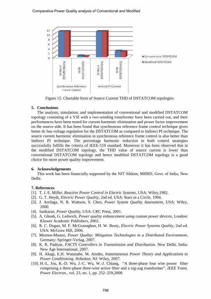
Figure 15. Chartable form of Source Current THD of DSTATCOM topologies
5. Conclusions
The analysis, simulation, and implementation of conventional and modified DSTATCOM
topology consisting of a VSI with a two-winding transformer have been carried out, and their
performances have been tested for current harmonic elimination and power factor improvement
on the source side. It has been found that synchronous reference frame control technique gives
better dc bus voltage regulation for the DSTATCOM as compared to Indirect PI technique. The
source current harmonic elimination in synchronous reference frame control is also better than
Indirect PI technique. The percentage harmonic reduction in both control strategies
successfully fulfills the criteria of IEEE-519 standard. Moreover it has been observed that in
the modified DSTATCOM topology, the THD value of source current is lower than
conventional DSTATCOM topology and hence modified DSTATCOM topology is a good
choice for more power quality improvement.
6. Acknowledgements
This work has been financially supported by the NIT Sikkim, MHRD, Govt. of India, New
Delhi.
7. References
[1]. T. J. E. Miller, Reactive Power Control in Electric Systems, USA: Wiley,1982.
[2]. G. T. Heydt, Electric Power Quality, 2nd ed. USA: Stars in a Circle, 1994.
[3]. J. Arrilaga, N. R. Wattson, S. Chen, Power System Quality Assessment, USA: Wiley,
2000.
[4]. Sankaran, Power Quality, USA: CRC Press, 2001.
[5]. A. Ghosh, G. Ledwich, Power quality enhancement using custom power devices, London:
Kluwer Academic Publishers, 2002.
[6]. R. C. Dugan, M. F. McGranaghan, H. W. Beaty, Electric Power Systems Quality, 2nd ed.
USA: McGraw Hill, 2006.
[7]. Moreno-Munoz, Power Quality: Mitigation Technologies in a Distributed Environment,
Germany: Springer-Verlag, 2007.
[8]. K. R. Padiyar, FACTS Controllers in Transmission and Distribution. New Delhi, India:
New Age International, 2007.
[9]. H. Akagi, E.H. Watanabe, M. Aredes, Instantaneous Power Theory and Applications to
Power Conditioning. Hoboken, NJ: Wiley, 2007.
[10]. H.-L. Jou, K.-D. Wu, J.-C. Wu, W.-J. Chiang, “A three-phase four wire power filter
comprising a three-phase three-wire active filter and a zig-zag transformer”, IEEE Trans.
Power Electron., vol. 23, no. 1, pp. 252–259,2008.
Comparative Power Quality analysis of Conventional and Modified
798

[11]. S.N. Sivanandam, S.N. Deepa, Principle of Soft Computing, New Delhi: Wiley India Ltd,
2010.
[12]. Rogor Jang Jyh Shing, Tsai Sun Chuen, Eiji Mizutani, A Computational Approach to
Learning and Machine Intelligence, Delhi: Person Education Asia,2008.
[13]. Parmod Kumar, Alka Mahajan, “Soft computing techniques for the control of an active
power filter”, IEEE Transactions on Power Delivery, vol. 24, no. 1, pp.452-461, 2009.
[14]. Avik Bhattacharya, Chandan Chakraborty, “A shunt active power filter with enhanced
performance using ANN-based predictive and adaptive controllers”, IEEE Transactions
on Industrial Electronics, vol. 58, no. 2, pp. 421-428, 2011.
[15]. Mahesh K. Mishra, K. Karthikeyan, “Design and analysis of voltage source inverter for
active compensators to compensate unbalanced and non-linear loads”, in 8th International
Power Engineering Conference, pp. 649 –654, 2007.
[16]. N. Singh, P. Rastgoufard, B. Singh, A. Chandra, K. Al-Haddad, “Design, simulation and
implementation of three-pole/four-pole topologies for active filters”, IEE Proceedings -
Electric Power Applications, Vol. 151, no. 4, pp. 467 – 476, 2004.
[17]. Nagesh Geddada, Srinivas Bhaskar Karanki, Mahesh K. Mishra, B. Kalyan Kumar,
“Modified Four Leg DSTATCOM Topology for Compensation of Unbalanced and
Nonlinear Loads in Three Phase Four wire System”, Proceedings of the 2011-14th
European Conference on Power Electronics and Applications (EPE 2011), 1 – 10, 2011.
[18]. S V Ravi Kumar, S Siva Nagaraju, “Simulation of D-STATCOM and DVR in power
systems”, ARPN Journal of Engineering and Applied Sciences, 2(3), pp7-13, 2007.
[19]. Pradeep Kumar, Niranjan Kumar, A K Akella, “A Simulation Based Case Study for
Control of DSTATCOM”, ISA Transactions, 53,767–775, 2014.
[20]. K Duffey Christopher, P Stratford Ray, “Update of harmonic standard IEEE-519: IEEE
recommended practices and requirements for harmonic control in electric power
systems”, IEEETrans Ind Appl, 25(6),1025–34,1989.
Pradeep Kumar born in India in 1985. He received the B.E.(Electrical
Engg) from GEC Bilaspur, India and M.Tech. (Electrical Engg) with
specialization of Control System from COEP, Pune, India in 2008 and 2010
respectively. His Ph.D. Degree is in Electrical Engg. Department, NIT
Jamshedpur ,India in 2017. He joined NIT Sikkim as an assistant professor.
His main research interests are control system, renewable energy system and
power quality.
Pradeep Kumar
799