Embed Size (px)
Citation preview

COMPARATIVE STUDY OF Bi-lnSn TERNARY
EUTECTIC CAST WIRES
Surajit Sengupta
A thesis submitteâ in conformity with the requirements
for the deg ree of Master of Applied Science
Graduate Department of Metallurgy and Materials Science
University of Toronto
Q Copyright by Surajit Sengupta, 1998

National Library l*l ofCanada Bibliothèque nationale du Canada
Acquisitions and Acquisitions et Bibliographie Services services bibliographiques
395 WeHington Street 395, rue Wellington OttawaON K1AON4 OttawaON K1AON4 Canada Canada
The author has granted a non- exclusive Iicence aiiowing the National Library of Canada to reproduce, loan, distribute or sell copies of this thesis in microform, paper or electronic formats.
The author tetains ownership of the copyright in this thesis. Neither the thesis nor substantial extracts from it may be printed or otherwise reproduced without the author's permission.
L'auteur a accordé une Licence non exclusive permettant à la Bibliothèque nationale du Canada de reproduire, prêter, distribuer ou vendre des copies de cette thèse sous la forme de microfiche/film, de reproduction sur papier ou sur format électronique.
L'auteur conserve la propriété du droit d'auteur qui protège cette thèse. Ni la thèse ni des extraits substantiels de celle-ci ne doivent ètre imprimés ou autrement reproduits sans son autorisation.

Dedicated to the memory of my mother
and uncle (Jethu)

COMPARATIVE STUDY OF Bi-InSn TERNARY
EUTECTIC CAST WlRES
BY Surajit Sengupta
Master of Applied Science
Graduate Department of Metallurgy and Materials Science
University of Toronto
1 998
Abstract A ternary eutectic Bi-lnSn alloy, which is brittle in nature and diffiwlt to
form by conventional methods, was successfully produced in the form of wire
2mm diameter by the Ohno Continuous Casting (OCC) process. The wire
produced has several unique features for example, superior surface finish, fine
microstruckire, uniform distribution of phases and consistent chemical
composition. In contrast statically cast samples exhibited segregation of bismuth
and double binary structures consisting of Bi ln~Sn and BiySn. In OCC samples
the matrix had a higher bismuth content and there was no evidence of
segregation. As a consequence of microstructural differences, wire produced by
the OCC technique had improved mechanical properties in terms of higher
strength and ductility compared to statically cast samples.

Acknowledgements
I would like to express sincere gratitude to my supervisors. Professor A. McLean
and Dr. H. Soda for their advice, encouragement and support throughout the course of
this thesis.
I also wouM like to acknowledge Dr. 2. Wang and Dr. J.W. Rutter for participation
in useful discussion.
I am grateful to Professor A. Ohno for the award of an Ohno Graduate Fellowship.
I am grateful for the financial support I received by University of Toronto Open
Fellowship and ALCAN award.
The technical support of Mr. F. Neub and Mr. Sal Boccia and the administrative
effort of the office staffs are deeply appreciated.
Finally I will ever remember the encouragement and the support from my wife,
Arpita; my son, Saswata and Babu-Ma.

Table of Contents
Page #
- Il
- 111
ABSTRACT - O
ACKNOWLEDGEMENTS
LIST OF FIGURES
LIST OF TABLES
CHAPTER 1: INTRODUCTION -
BASIC PRINCIPLE OF OHNO CONTINUOUS
CASTING - - O - CHAPTER 2:
CHAPTER 3: LITERATURE SURVEY - O O - 3.1 Lead alloys - O - O
3.2 Effect of bismuth on mechanical properties - 3.3 Microstructure of eutectic alloys - O
3.4 Segregation - -
CHAPTER 4: EXPERIMENTAL ASPECTS - O
4.1 Alloy preparation O O - Equipment O - O
Experimental procedure O
Static casting facility O - Experimental procedure for static casting
Sample grip design for mechanical testing
for tensile test
for microstructural
Sample preparation
Sample preparation
IV
observation-

CHAPTER 5:
CHAPTER 6:
RESULTS AND DISCUSSION - - O
5.1 Evaluation of casting condition for OCC - 5.1.1 The occurrence of breakout - - 5.1.2 Surface appearance of cast wire -
5.2 Microstructure - O - O
5.2.1 Microstructure of static cast rod - 5.2.2 Microstructure of OCC wire - -
5.3 Compositional uniformity in OCC samples - 5.4 Mechanical properties - O - - 5.5 Fracture surface of OCC and statically
cast samples - - -
CONCLUSIONS AND FUTURE WORK
6.1 Conclusions - O
6.2 Future work - - -
Page #
- 41
- 41
- 41
- 43
REFERENCES

LIST OF FIGURES Page #
Figure 1
Figure 2
Figure 3
Figure 4
Figure 5
Figure 6
Figure 7
Figure 8
Figure 9
Schematic diagram showing the principle of OCC and the
difference with conventional continuous casting - O
Different morphologies of binary eutectic alloys - - Different morphologies of ternary eutectic alloys - - Liquidus projection of Bi-ln-Sn system showing 350.5 K
ternary eutectic (24) - O - O
Schematic diagram of OCC equipment for generation of net
shape wires - O - O - Temperature profile during casting - - - O
Schematic diagram of resistance furnace for static casting in
a glass mold - - - - - - - Temperature profile inside the glass tube showing a plateau
region and a temperature gradient region - - O
Photograph of graphite split mold - O - Figure 10 Schemaüc diagram of resistance furnace for static casting in
graphite mold - - - O .. Figure 11 Temperature profile inside the mold cavity - - Figure 12 Photograph of INSTRON machine, mode18501 - Figure 13 Schematic diagram showing the problem associated with
INSTRON grip - - O O - - Figure 14 Photograph of modified grip, longitudinal and transverse
views - - - - 0
Figure 15 Schematic diagram of modified grip - - - Figure 16 Photograph of OCC wire and statically cast produds showing
significant difference in surface quality O

Page #
Figure 17 Cooling curve of the melt solidified inside the glass tube
showing the freezing point of eutectic alloy - 46
Figure 18 Backscattered SEM image of sample from the plateau region
of cast product in glass tube showing the phenornenon of
segregated blocks and complex regular structure of bismuth
(white phase) O - - - 47
Figure 19 Backscattered SEM image of sample from the temperature
gradient reg ion in glass mold showing directional solidification
and less segregation - O O - O - - 48
Figure 20 Energy dispersive X-ray (EDX) spectra showing,
a) Segregated bismuth,
b) Gray phase composed of bismuth and indium inside mottled
reg ion of bismuth complex regular structure,
C) Black dendrite composed of tin with a trace of bismuth,
d) Gray spine phase inside eutectic cell cornposed of bismuth.
indium and tin O O - 9 9 - 49
Figure 21 Backscattered SEM image of eutectic cell showing segregated
white bismuth phase in the fom of complex regular structure
around grain boundary, bismuth-indium gray spine and mottled
region of tin dendrite - - O O - 55
Figure 22 EDX analysis showing the presence of three elements
Bi, Sn and In in the decomposed structure of Bi complex regular
structure - - - - 9 - - - - 56
Figure 23 Backscattered SEM image showing a) the cubic, b) the fish
spine and c) the trigonal shaped complex regular structure of
bismuth - - - - - - 57

Page #
Figure 24 Backscattered SEM image showing the precipitation of
bismuth and tin in gray matrix and absence of gray region
where black tin phase is narrow - - - - Figure 25 Backscattered SEM image of complex regular structure - Figure 26 Backscattered SEM image of complex regular structure
Figure 27 Decomposed Sn dendrite showing several colonies or cells
having lamellar structure - - - - O
Figure 28 Backscattered SEM image of OCC wire, casting speed
14mm/min O O - - O - O
Figure 29 Backscattered SEM image of OCC wire, casting speed
79mmimin O - O - - - O
Figure 30 EDX spectra of OCC wire showing,
a) White pure bismuth phase, b) Black dendritic tin phase,
c) Gray matrix phase without tin O - O
Figure 31 Backscattered SEM image of OCC wire, casting speed
14mmiminl showing a) tin dendrite and associated bismuth and
b) at higher magnification O - - O - - 68
Figure 32 Plot to confirm compositional uniformity measured at different
Locations - - O - O - O - 72
Figure 33 Backscattered SEM image of statically cast rod accepted for
tensile test. Segregated bismuth was removed by machining
during sarnple preparation - - - - - - 76
Figure 34 Schematic diagram of tensile specimen - - - 76
Figure 35 Photograph of turnings to show difterence in material proopeities
between OCC and statically cast samples - - - 77

Figure 36 Comparison of elongation values between OCC and
statically cast samples at a crosshead speed of 1.25mmlmin
Figure 37 Cornparison of elongation values between OCC and
statically cast samples at a crosshead speed of 2.5rnrnfmin
Figure 38 Comparison of elongation values between OCC and
statically cast samples at a crosshead speed of 5mmlrnin
Figure 39 Cornparison of elongation values between OCC and
statically cast sarnples at a crosshead speed of 7.5mmlmin
Figure 40 Cornparison of elongation values between OCC and
statically cast sarnples at a crosshead speed of 10mmlmin
Page #
- 79
- 80
- 81
- 82
- 83
Figure 41 Plot of yield stress vs. crosshead speed showing the low value
of yield stress at higher crosshead speeds which produces
premature failure of the statically cast samples and the high
and consistent yield stress values of OCC samples - - 88
Figure 42 Plot of ultimate tensile stress vs. crosshead speed showing,
a) significant inconsistency in UTS for statically cast samples
at higher crosshead speed and b) higher and more consistent
UTS of OCC samples - - - - - - - 89
Figure 43 Plot of elongation vs. crosshead speed showing the greater
ductility of OCC samples compared to statically cast samples - 90
Figure 44 Fractography after tensile test at a crosshead speed of
1.25mmlmin. Both OCC and statically cast samples are ductile
in nature showing high reduction in area - - - - 93

Figure 45 Fractography after tensile test at a crosshead speed of
2.5mmlmin showing no significant difference in reduction
of cross-sectional area - - Figure 46 Fractography after tensile test at a crosshead speed of
Smmlmin showing the evidence of ductility for both OCC
and statically cast samples - - O - - Figure 47 Fractography after tensile test at a crosshead speed of
7.5 mmlmin showing the ductile fracture of OCC sample
and brittle fracture of statically cast sample
Figure 48 Fractography after tensile test at a crosshead speed of
Page #
- 94
- 95
- 96
l0mmlmin showing, a) high reduction in cross-sectional area
and ductile nature of fracture surface of OCC sample,
b) cleavages and no reduction in area on fracture surface
of statkally cast sample - - - - 97
Figure 49 Fractography of tensile test sample at a crosshead speed of
1.25mmhin and at high magnification - O - - 98
Figure 50 Fractography of tensile test samples, at a crosshead speed of
i0mmlmin and at high magnification - - - 99
Figure 51 SEM secondary image showing voids along the grain boundary
of a statically cast sample - - - - 100
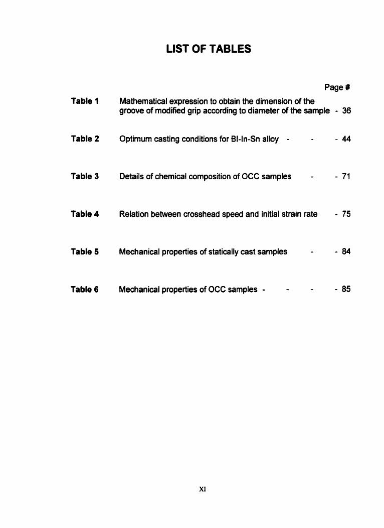
LIST OF TABLES
Page #
Table 1
Table 2
Table 3
Table 4
Table 5
Table 6
Mathematical expression to obtain the dimension of the groove of modified grip according to diameter of the sample - 36
Optimum casting conditions for BI-ln-Sn alloy - -
Details of chemical composition of OCC samples -
Relation between crosshead speed and initial strain rate
Mechanical properties of statically cast samples -
Mechanical properties of OCC sarnples - - -

CHAPTER 1
INTRODUCTION
Ohno Continuous Casting (OCC) was developed at the Chiba lnstitute of
Technology in Japan. The name of this special type of casting was after the
pioneer of this process, A. Ohno. The idea of this process was to manufacture
alloys that are difficult to produce or that cannot be rolled, drawn, or extruded. In
conventional continuous casting the mold is cooled to solidify liquid metal inside
the mold to avoid run out of liquid metal at the mold exit. But the frictional force
between the mold wall and the cast strand creates surface defects. Apart from
surface defects the cast product processed through a cooled mold may have
different types of cast defects like shrin kage cavities, blowholes and surface
defects. So cast products have to undergo subsequent processing like surface
grinding for a better surface finish, annealing for microstructure and property
improvernent, hot or cold rolling for final required shape and desired properties.
The addition of further processing increases the cost of production.
There is a need for net shape cast products where the cross-sectional
area is very small and the high quality surface finish without any cast defect is an
advantage. There are different methods, the most common is wire drawing to
produce products at fast rate in wire form. But if the metal or alloys are brittle and
strain sensitive the drawing speed has to decrease drastically and sometimes it
cannot be produced. Soda et al (1) found that casting of bismuth which is fragile
and brittle in nature can be cast in wire fom by the OCC process. It should be
noted that bismuth expands during solidification and this would increase frictional
force during conventional casting. Wth the OCC proœss, single crystal bismuth
wire was produced which was ductile in nature. In other work Soda et al (2)
produced wire of diameter 1.7-2 mm with alloys having composition aluminum
1.5-7 wt % yttrium. The main feature of the wire was that it was unidirectionally
solidified with cellular or dendritic microstructure having constant unifonn
I
chemical composition along the length with excellent dimensional stability.
Considering the brittleness and small cross-sectional area, some aluminum
based alloys are difficult to produce or cannot be produced despite the fad they
are useful for surface hardening for the improvement in mechanical properties.
Again OCC was the only way to produce successfully aluminum with 25.50% Cu
and Al-Cu-Si alloys which are brittle in nature and ditficult to process in one-step.
It can be seen from the above brief discussion that with the OCC method
we can produce alloys which are brittle in nature and are difficult and in sorne
cases impossible to produce by conventional methods.
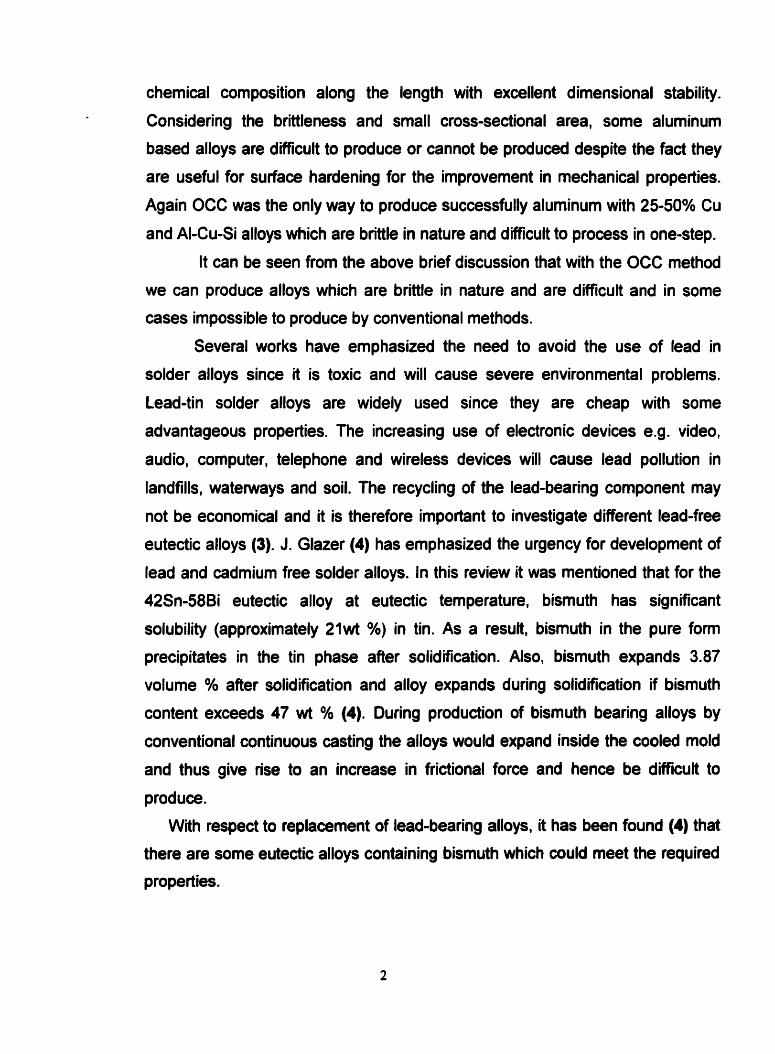
Several works have emphasized the need to avoid the use of lead in
solder alloys since it is toxic and will cause severe environmental problerns.
Lead-tin solder alloys are widely used since they are cheap with some
advantageous properties. The increasing use of electronic devices e.g. video,
audio, computer, telephone and wireless devices will cause lead pollution in
landfills, watennrays and soil. The recycling of the lead-bearing component may
not be economical and it is therefore important to investigate different lead-free
eutectic alloys (3). J. Glazer (4) has emphasized the urgency for development of
lead and cadmium free solder alloys. In this review it was mentioned that for the
42Sn-58Bi eutectic alloy at eutectic temperature, bismuth has significant
solubility (approximately 2iwt %) in ün. As a result, bismuth in the pure form
precipitates in the tin phase after solidification. Also, bismuth expands 3.87
volume % after solidification and alloy expands during solidification if bismuth
content exceeds 47 wt % (4). During production of bismuth bearing alloys by
conventional continuous casting the alloys would expand inside the cooled mold
and thus give rise to an increase in frictional force and hence be difficult to
produce.
With respect to replacement of lead-bearing alloys, it has been found (4) that
there are some eutectic alloys containing bismuth which could meet the required
properties.

The following features summarize the advantages of bismuth bearing alloys
for use as solders,
Bismuth bearing alloys have a wide range of rnelting temperature from 72°C
to 212°C. This is required to widen the range of applications under different
conditions.
Like lead, if bismuth is added to t h it reduces the surface tension and
improves the wetting behavior.
Sn-Bi alloys provide a better matching of thermal expansion coefficients with
a copper substrate than Sn-Pb alloy.
In the present study a ternary eutectic alloy that has the maximum proportion
of bismuth in weight % and is brittle in nature was selected from Bi-ln-Sn system.
The composition of this alloy in weight % is 57.2 % Bi, 24.8 % In and 18 % Sn
and the eutectic temperature is 77°C.
from the manufacturer point of view, the high bismuth content of this alloy
can create problems due to brittleness with conventional casting processes.
Even if this alloy could be produced, the breakage of the product during
transportation would create loss. Again if this alloy is to be used in coiled wire
form it cannot be produced by conventional methods since the increased number
of processing steps would increase the cost of production. The airn in this study
was to produce this material in one step as net shape wire with minimum
standard deviation in cross-sectional area and a smooth defect free surface. A
further objective was tu conduct a comparative study on microstructure and
mechanical properties between OCC wire and statically cast product.
Considering al1 of the factors mentioned the main objectives of the present
study are as follows,
To continuously cast a lead free ternary eutectic alloy which may be quite
impossible to produce by the conventional casting process.
To generate net shape cast wire of srnall cross-sectional area with good
surface quality, free from intemal defeds and with minimum deviation in
dimensional stability.

To make a comparative microstructural study and check segregation
behavior within OCC wire and statically cast products.
To compare the mechanical propeiiies of OCC wire and statically cast
products.

CHAPTER 2
BASIC PRINCIPLE OF OHNO CONTINUOUS CASTING
During the 1980's Professor A. Ohno of Chiba lnstitute of Technology,
Japan pioneered the development of Ohno Continuous Casting and its
application in various fields of casting (5).
In general the casting process involves the solidification of liquid metal
following different rates of heat extraction to obtain the desired shape and
properties simultaneously. The mechanical properties of the cast product depend
on the size and orientation of the grains. To obtain consistency of mechanical
properties, phases should be distributed uniformly through out the matrix. In the
early 1970's the formation mechanism of equiaxed grains was investigated
(6,7,8). It was found that equiaxed grains fomed at the mold wall at the initial
stage of solidification and were carried to the center of the ingot through
convection. These works led to the development of the Ohno Continuous Casting
(OCC) process (5).
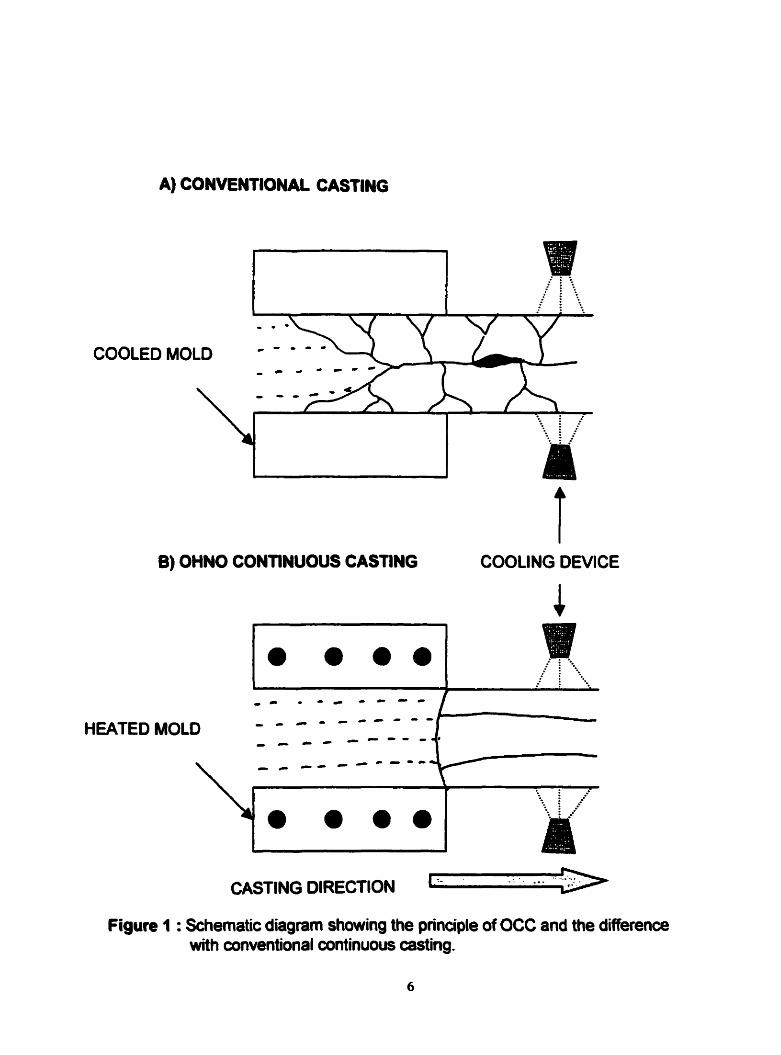
Figure 1 shows the main difference between the OCC and conventional
continuous casting process. In conventional casting process the mold is water-
cooled and the nucleation of the crystals starts at the mold surface. The growth
direction is from mold surface toward the center of the cast strand and
perpendicular to the casting direction and thus a multi-crystalline product is
produced. Cooled mold solidification leads to formation of segregation and
shrinkage cavities. Since solidification starts at the mold surface, this is the
source of frictional force between the mold and the cast strand. For the casting of
brittle and strain sensitive material with small cross-sectional area the frictional
force betvireen mold and cast strand could be high enough to cause breakage
and interruption during casting.
A) CONVENTIONAL CASTING
COOLED
B) OHNO CONTINUOUS CASTING
- -. . CASTING DIRECTION
...
Figure 1 : Schematic diagram showing the principle of OCC and the difference with conventional continuous casting.
In the OCC process the mold is not cooled but heated externally and the
temperature of the mold is kept above the melting point of the metal to be cast.
The cooling device is positioned in front of the mold exit to extrad heat from the
cast strand in a direction parallel to casting direction. In this way unidirectional
solidification is possible and under specific casting conditions, cast products with
a long single crystal can be produœd. The distance of the cooling device from
the mold exit can be adjusted according to the casting speed. In the OCC
process the nucleation of crystals on the mold wall is avoided and frictional force
between mold and cast strand can be minimized. Reduced friction helps to obtain
net shaped products of small cross-sectional area with a smooth surface finish,
which eliminates surface defects.
Thus OCC process can improve the properties of the cast product in
several ways. A review report by Ohno (9) detailed the features that can be
achieved through OCC process as follows,
An alternative route to conventional casting processes where it may be
difficult to produce cast products from brittle materials having a small and
complicated cross-sectional area.
Production of cast products having unidirectional or single crystal
microstructure with improved mechanical properties.
Generation of net or near net shape cast products having a smooth surface
quality and freedom from defects such as shrinkage cavities and blowholes.
Elimination of the requirements for further processing and minimization of the
cost of production.
Provision of good workability.

CHAPTER 3
LITERATURE SURVEY
3.1 Lead alloys
The toxicity of lead and its alloys is well known. For example the safe
drinking water a d amendments U.S., 1986, prohibited the use of lead pipe and
lead containing solders for drinking water lines. Recently the US. environmental
protection agency regulations considered the ban of lead-containing solders (3,4,
10,ll). The increasing use of electronic equiprnent and the use of lead-bearing
solders may create a severe pollution problem not only on the industrial shop
fioor, but also during disposal and the subsequent effect on the environment.
Lead-free solders available are based on tin, indium or bismuth alloy systems.
Other elements are added to lower or increase the liquidus temperature (12).
3.2 Effect of bismuth on mechanical properties
Shewmon (13) considered the effect of bismuth on the mechanical
properties of cast gold. It was observed that an addition of only 0.2 % bismuth in
gold reduced elongation and ultimate tensile strength to zero. The fracture
surface was crystalline, which indicated brittle fracture. It was also observed that
the solid solubility of bismuth in gold was low. It was found that liquid metal
embrittlement occurred at low fracture stress with increase in bismuth
concentration.
Kariya and Otsuka (14) studied the effect of bismuth in Sn-3.5 % Ag alloy.
They found that the addition of bismuth beyond 2 % advenely affected the
fatigue life of the alloy. Fatigue life is defined as the nurnber of cycles at which
the stress is half of the maximum initial applied value. They found that addition of
bismuth increases the tensile strength due to solid solution hardening or 8

strengthening due to dispersed particles of bismuth but the ductility in ternis of
reduction in area decreases dramatically . Glazer (4,ll) emphasized the importance of physical and mechanical
properties of lead-free ailoys. Studies of solder alloys include the investigation of
melting temperature, surface tension, electrical resistivity, microstructure, and for
mechanical properties, time independent monotonic tensile strength, shear
strength and elongation as well as time dependant monotonic temperature
related creep. Homologous temperature is defined as the ratio of working
temperature to rnelting temperature in absolute scale. Since the melting point of
solder alloy is low, long exposure to a temperature which exceeds 50% of the
homologous temperature is important because it may give rise to grain growth
phenomenon which affects the creep retated properties. Thus fine microstructure
is important to obtain improved mechanical properties.
Mei and Morris (15) stated that mechanical properties are dependant on
microstructure, the combination of phases and their distribution, which depend on
several factors. Faster cooling rates yield fine microstructure. Sig nificant
microstructural differences and their effect on improved fatigue life due to cooling
rate have been observed in the case of Pb-Sn alloy. In the case of lead free
alloy, these investigaton did not mention about cooling rate, which is an
important issue with respect to the solder microstructure and its mechanical
properties.
McCormack et al (16) noted several improvements during investigation of
Bi-Sn solder alloys as a substitute for Pb-Sn alloy. Bi-Sn eutectic alloy has a low
melting temperature (139°C) and this penits the use of inexpensive circuit
board. They exarnined the importance of faster cooling rates and the addition of
grain refiner on microstructure. After quenching in ice water, they found that for
the same sample the abrupt strain rate sensitivity changed from 60 inchlinch to
10 inchlinch with increasing strain rate from O.Ol/second to 0.1Isecond. Again at
a strain rate of 0.01lsecond the total strain was 10 % and 28% for slowly and
forced air-cooled samples respectively. It is expected that the forced air-cooled
samples would have finer microstructure. It was menüoned that the strain rate

sensitivity was due to the bismuth rich phases and their continuity. Silver was
added as grain refiner, but special precautions are necessary to avoid an excess
of silver and the formation of high melting point phases.
Jin and McComack (17) examined the behavior of Bi-43%Sn eutectic
alloy and reported a "lamella like microstructure" composed of p-Sn and Bi phase
when solidified to roorn temperature. From binary diagram of Bi-Sn it can be
observed that Sn has partial solid solubility with bismuth. At approximately
100°C, in Bi-Sn system the Sn rich side shows that approximately 10% of
bismuth dissolves into the P-Sn phase. On cooling to room temperature bismuth
precipitates in coarse P-Sn phase. It also undergoes signifiant microstructural
coarsening resulting in a nonuniform distribution of phases which affects
mechanical properties. To obtain fine microstructure these authors added
dispersed particles to inhibit grain growth and serve as nucleation sites. The
condition related to the selection of such dispersoids was that there should be no
solubility or reactivity with the matrix. To obtain uniform distribution and thereby
avoid agglomeration of the dispersoids, a novel magnetic distribution technique
was proposed.
3.3 Microstructure of eutectic alloys
Depending on the morphology of the microstructure a binary eutectic
structure can be classified as either regular or irregular. In the regular class,
lamellar or rod like structures of two phases are fonned whereas in the irregular
structure one phase forms skeletal faceted crystals and the other nonfaceted
phase grows inside the first, with the formation of a complex regular structure
(18). Croker et al (19) investigateâ different morphologies of eutectic binary
alloys. They concluded that at a given growth rate if the entropy of solution and
relative volume of each phase are known the unknown structure of a particular
eutectic alloy can be predicted. Binary eutectic alloys can also be classified into
three categories depending on the nature of the solid-liquid interface (20). In a
binary system with Wo phases, three different types of interface are possible: 1 O

nonfaceted-nonfaceted, faceted-nonfaceted and faceted-faceted. The
morphology of the microstructure depends on the type of interface, local growth
condition and temperature gradient. For example, in a binary eutectic structure
with h o phases A and B, if both A and 6 are nonfaceted then the morphology
will be regular lamellar or rod like. If one of the phases is faceted and the other
nonfaceted then this will produce either irregular or complex regular
microstructure. The complex regular structure is due to the ingrowth of a
nonfaceted phase inside the faceted phase (20). This forms a skeletal structure
with different shapes which depend on the local solidification condition. In Figure
2 different morphologies of microstructures have been displayed for binary
eutectic alloys (20,21).
In the case of ternary eutectic alloys, three-phase lamellar structures have
been reported. The combination of ABCBA regular lamellar structure is found in
the Pb-Sn-Cd systern (22), Figure 3a. Pb-Sn grew in a coupled manner, but not
Sn-Cd due to the requirement of high interfacial energy due to the presence of
Cd faceted phase. Another lamellar structure was observed in one of the eutectic
compositions (melting point 332°K) of the Bi-ln-Sn system (23). It was observed
that fibers of In rich phase and Sn rich phase fonned a regular structure in a
matrix of Mnz phase, Figure 3b. However a regular lamellar morphology of
ABCABC was not reported.
Ruggiero and Rutter (24) examined the microstructure of the eutectic alloy
57.2 % Bi, 24.8 % In and 18 % Sn with a solidification temperature of 77S°C.
They used a technique of slow unidirectional growth with a growth rate of 0.74-
53mmlday and quenched the sample to reproduce the solid-liquid interface. With
slow growth rates up to a maximum of 1 .ômmtday the microstructure consisted of
two regions Biln-y Sn and massive Bi, Figure 3c. With increase in growth rate,
two regions of binary structures are found, Biln-y Sn and Bi-y Sn, as shown in
Figure 3d. According to the morphology of the microstructure the lamellar Biln-y
Sn was described as a quasi-regular structure. Biln was observed as faceted
phase and y Sn as non-faceted and according to the classification this binary
structure should be under irregular class, but the morphology is regular lamellar
11

structure of Biln and y Sn and hence termed as quasi-regular. The other Bi-y Sn
binary structure was a complex regular structure due to the faceted bismuth
phase. In both binary structures y Sn, common to both binary phases, is non-
faceted. It was suggested that the hexagonal ySn phase decornposed below the
eutectic temperature by a ternary eutectoid reaction to form PSn, Biln and Bi
phases. In the case of Bi-y Sn complex regular structure, bismuth of decomposed
structure was not present. It was suggested that in the case of Biy Sn complex
regular structure, bismuth has either diffused or been incorporated inside the
bismuth phase.
In the Bi-Cd-Sn system Ruggiero and Rutter found that the three phases
formed were Bi, Cd and P Cd-Sn. P Cd-Sn is a hexagonal Sn rich phase of Cd-
Sn binary system. The growth rates, frorn 8 nmlsec to 1.1 pm/sec, were used
and the three phases were not an intimate mixture (25). At a higher growth rate
the morphoiogy was, a quasi-regular or complex regular binary structure of Bi
and p Cd-Sn, outlined by Cd flakes. At slower growth rate a regular lamellar
microstructure of Cd and PCd-Sn was often formed with large and irregular
masses of Bi. It should be noted that pCd-Sn is non-faceted and common to both
binary structures. The evidence of ternary eutectic decomposition was also
observed in the Bi-Cd-Sn system where pCd-Sn decomposed into Bi, Cd and a-
Sn.
Also in the Bi-Cd-Pb system Ruggiero and Rutter have referred to regions
of double binary structure with the formation of a quasi-regular binary structure of
Bi and Pbz6i (26). The second binary structure consists of broken larnellar Cd
and Pb2Bi, where PbzBi is a non-faceted phase and common to both binary
structures. The growth rate range in this study was from 10.6 nmlsec to
555nmlsec.
In general it was observed that in the case of double binary structures one
non- faceted phase is common to both binary structures. All the eutectic alloys
reported were solidified under very siow growth rates in the range of 5.7 nmlsec
to 53 mmlday and there was no report related to higher growth rate.

In some bismuth bearing alloys the formation of massive blocks of bismuth
has been reported when the slowest growth rate was maintained depending on
the binary or temary system used (20,23,24-28). For example (24) in the slowest
growth rate of 0.74mmlday and 1.6 mmlday, the bismuth was found in block
shape. When the growth rate was beyond 1.6 mmlday complex regular structure
of bismuth with y Sn was fomed. It was suggested that the complex regular
structure was due to the presence of a faceted bismuth phase. All directional
solidification experiments were carried out under controlled temperature
gradients and at very slow growth rates. It is expected that due to the higher
density of the Bi phase than bulk liquid that bismuth would segregate, but there
was no report of this.
The growth of dendrites in eutectic composition has been observed
(27,28) when the alloy system has a skewed coupled zone below the eutectic
temperature.
3.4 Segregation
Segregation results in the non-unifonn distribution of different phases and
affects consistent mechanical behavior. Segregation is the result of 1 ) rejection of
solute at the solid-liquid interface during solidification and its distribution by
diffusion and mass flow away from solidification front, 2) nucleation of primary
phase and segregation depending on the density of the primary phase with
respect to the bulk liquid. For example segregation was reported for Sn-Pb
eutectic alloy (29) in which primary lead dendrites nucleated in the undercooled
rnelt and segregated to the bottom of the ingot whereas tin rich dendrites
segregated to the top.
Grugel (30) studied a macrosegregation phenornenon in lead-tin alloy
during unidirectional solidification. Two alloy compositions, Pb-45Sn and Pb-
75Sn, were selected. In the case of Pb-45Sn hypoeutectic alloy the primary lead
dendrites rejected less dense tin rich eutectic. In vertical casting the tin rich
13

eutectic was found between the Pb dendrites and in the case of horizontal
casting the lin rich eutectic phase segregated to the top since it was less dense.
For the other alloy, Sn was the primary dendrite phase and the denser lead rich
phase segregated to the bottom in horizontal casting. Microstructural
homogeneity was absent in both cases due to segregation. To obtain uniform
distribution of the segregated phase, different positions and furnace rotation were
checked. The most suitable condition to minimize the segregation was obtained
by an axial rotation of the furnace at 10 rpm and positioning it at an angle of 5"
from the horizontal position. However there was a lack of technical information
and this appeared to be a trial and error method. No suggestion was made to
minimize segregation where gravitational force is involved.
Segregation in continuous casting of steel and the adverse effect on
mechanical properties, Le., tensile, fatigue and impact toughness has been
reported (31,32). The mass movement is greatly influenced by convectional force
and depends on solute concentration difference, temperature difference in the
liquid and gravitational forces on crystals growing in the liquid. It has been
observed that the segregation of carbon, sulphur and to a lesser extent
manganese and phosphorus has resulted in non-uniform mechanical properties.
It was found that segregation tened as centerline segregation increases with the
increase of the columnar region. This segregation which decreases the reliability
of continuously cast steel is minimized by electro-magnetic stirring methods
(EMS). This promotes the formation of equiaxed grains by increasing the
convective flow which promotes the separation of dendritic tips. The detached
dendritic üps settle within the liquid pool and act as nuclei for the formation of
equiaxed crystallization . The purpose is to d istribute rejected solute unifomly
throughout the entire structure and thus obtain more uniform mechanical
properties.

Lamellar CU-AI eutedic (21)
a) Reguîar microstructure
As polished (nat etched) 200 X
3 105 Scctlon of a castine show- the N-Si eufecttc, which consists of
short prrrtlcles of siilcon tdark) la rn aluminum matrb. Some particles ue con- nected in the plaac shown; othus are con- nectai in other plones. (Red 1)
As polished (not etched) 400 X Same casting as in 3097, but a sec- 3098 ,* ,,, ,&, , ,muon
of solldîficatlon. showing the c h u l u cmss section of the dark, fibrous putlclcs of MnSb phase In the antimony xnatrix.
Rod like Mn-Sb eutedic (21)
Needle shaped AI-Si eutedic (21) Cornplex regular BiSn euteaic (20) b) Imegubr microstructure
Figure 2 : Different morphologies of binary eutecüc alloys.

a)Lamellar structure in
temary eutedic (22)
Pb-Sn-Cd b) Lamelhr structure in Bi-Sn-ln
temary eutectic (23)
c) Quasi-reg ular lamellar strudure
with blocks of bismuth in Bi-Sn-ln
temary eutectic at slow growth rate
(24).
d) Double binary structure composed of
quasi-regular and cornplex regular
regions in Bi-Sn-ln temary eutecüc at
faster growth rate (24).
Figure 3 : Different morphologies of temary eutectPc alloys.

CHAPTER 4
EXPERIMENTAL ASPECTS
4.1 Alloy preparation
The composition of the alloy was selected from one of the ternary
eutectics within the Bi-ln-Sn system as shown in Figure 4 (24). The composition
in weight percentage is 57.2% Bi, 24.8% In and 18% Sn and the melting point of
the alloy is 77S°C (33). All the individual metals were 99.99% in purity as
received from the supplier. Bismuth was received in tear shaped grains with a
dull surface appearance due to the presence of oxide. To get rid of oxide the
bismuth grains were melted in a graphite crucible in the presence of argon gas.
The oxide was removed from the top of the melt and the clean melt was poured
into a shallow graphite mold. Tin was received as a large block and melted in the
same way to obtain thin strip. Indium was received in a sealed condition.
Bi, In and Sn were weighed according to the exact proportion for the alloy
composition and placed in a graphite cylindrical crucible. The crucible was
heated extemally by propane torch and argon gas was supplied from above to
avoid any oxidation during melting. The mixture was stirred with a glass rod to
ensure homogeneity. To obtain small pellets to facilitate feeding during casting
and avoid segregation, the melt at a temperature of approximately 95' C was
poured in a stainless-steel vessel containing water. The solidified pellets were
rernoved from water and dried at room temperature. The composition of the alloy
was confirmed by neutron activation analysis and melting point measurements.

Figure 4: Liquidus projection of Bi-ln-Sn system shdng 350.5 K
temary eutectic (24).
4.2 Equipment
Figure 5 shows a schematic diagram for producing wire by the OCC process.
The melting and casting apparatus was constructed from a 37mm long and 30
mm diameter graphite rod. An open cavity at the middle of the graphite rod was
made to hold molten metal and to melt the alloy. The dimension of the cavity was
16mm wide, 25mm long and 20mm deep. A channel was drilled at one end of the
mold cavity length 4mm and diameter 2mm.
A heating element was prepared from nichrome wire of 0.45mm diameter.
The wire was coiled around a graphite crucible coated with alumina cernent for
electrical insulation and then protected by another layer of alumina to avoid
mechanical damage during handling.
The control K-type thenocouple was calibrated with boiling water and an ice-
water mixture and a correction factor was determined. A hole 4mm deep was
drilled on top of the graphite crucible near the mold cavity channel at a position
1 mm away from the channel entrance.
In front of the mold exit a cooling device was attached to a movable platform
to adjust the position from the mold exit. The cooling device consists of a pipe
having 2mm inner diameter and connected to a water supply source. A stopper
valve fixed in between the delivery and supply lines controlled the flow rate of
water.
A stainless-steel pipe 2mm outer diameter and 1 meter long was used as a
dummy bar to initiate freezing from the channel at the beginning of the casting. A
steel wire ?cm in length and 1mm in diameter was attached to one end of the
dummy bar to insert it smoothly inside the channel. The pinch rollen were
connected with a gear and chain mechanism and this arrangement was
connected to a variable speed control motor, so that withdrawal speed of the cast
product could be controlled.

HEATER THERMOCOUPLE
WATER COOLER LlQUlD METAL
- CASTING DIRECTION
INSULATOR I
SOLID- LlQUlD INTERFACE
Figure 5 : Schematic diagram of OCC equipment for generation of net shape wires.
A horizontally placed platfon was positioned in between the water cooler
and pinch roller and the dummy bar was passed through a glass tube fixed on
top of the platform. In this way mechanical vibration dumg casting was reduced.
4.3 Experimental procedure
The graphite crucible and heater, was aligned to ensure that the mold cavity
channel was at the same level as the dummy bar and pinch roller.
The dummy bar was inserted through the pinch roller and then through the
glass tube on the movable platform. The steel wire connected with the dummy
bar was introduced inside the mold channel. The dummy bar was located
between the rollers with the help of a manual turning screw on the top rollers. An
adjustable knob attached to the control panel was used to regulate the speed of
the motor.
The water Row rate was fixed at 150mL per minute. The rate was maintained
the same for different casting speeds. The furnace was switched on and the
control thermocoupfe temperature adjusted to obtain a melt temperature of 87°C
at position B (Figure 5), during casting. Small pellets of alloy were fed inside the
moid cavity. In the liquid state the height of the metal head was 6mm from the top
of the channel entrance at the start of casting. During casting the metal head
height was maintained within the range of 3-6 mm to ensure appropriate metal
pressure at the mold exit.
The speed controller was set to the desired casting speed and the distance
behnreen the mold outlet and the cooler adjusted to bring the solidification front
just outside the mold exit.

LENGTH (mm)
. -- - - - .
I
* t * l
Length inside mold cavity Solid-liq uid interface
Length of mold channel
Figure 6 : Temperature profile during casting.

When the melt temperature was 87°C at the channel entrance, a temperature
profile was measured as shown in Figure 6. The temperature was measured
from point A to B inside the mold cavity at a distance interval of 5mm. Then the
temperature was measured at the mold exit and the temperature at the solid-
liquid interface was considered to be the solidification temperature of the alloy.
The control themocouple temperature was recorded as reference to follow the
particular temperature distribution.
During casting of wire 2mm in diameter, with the above temperature profile,
the most suitable distance between the mold exit and cooler was 4mm and 5mm
for casting speeds of 79mm/min and 14mm/min respectively.

4.4 Static casting facility
Statically cast rod was produced inside a glass tube, 3.2mm inner
diameter. A hollow cylindrical furnace blocked at one end was prepared as
shown in Figure 7. A nichrome wire 0.45mm diameter was coiled around the
alumina cement protection over the furnace. Then another layer of alumina
cernent was applied to cover the coil. The purpose was to insulate the heating
coi1 and protect it from mechanical damage. A control themiocouple was
positioned in a hole drilled about Imm away from point B and 4mm in depth. The
glass tube was positioned at the center of the fumace and kept horizontal. The
control thermocouple temperature was adjusted to obtain a minimum
temperature of 87°C at point B of the glass tube to ensure the alloy was in the
liquid state. When the temperature was stable, a temperature profile was
measured at intervals of 5mm from point A to point 6 as shown in Figure 8. From
the plot of temperature vs. distance it was found that from point A the
temperature was essentially constant for a distance of approximately 60mm. This
was designated as the plateau region. From 60mm to point 6 a temperature
gradient reg ion exists. Unidirectional solidification was expected in the
temperature gradient reg ion.
To perform mechanical testing the minimum length of sample required
was 100mm and efforts were made to maintain the same morphology of structure
along the entire length of the sample. A problem associated with the glass mold
was that there was no gap between the cast metal and the glass wall due to
negligible thermal contraction of the alloy since the alloy has a high bismuth
content and bismuth expands when solidified. To remove the specimen, the
glass mold had to be broken and the specimen also broke into pieces. Thus the
length of the specimen was insufficient for tensile tests. Difterent structural
rnorphology in the plateau and temperature gradient regions was expected and
the results will be discussed later. To resolve the breakout problem a graphite
split-mold, Figure 9, was designed.

HEATER ALUMINA CEMENT f HERMOCOUPLE
BLOCKED END
Figure 7 : Schematic diagram of resistance fumace for static casting in a glass mold.

I PLATEAU REGION 1 GRADIENT REGlOl
90 - GLASS MOLD
80 -
LENGTH (mm)
Figure 8 : Temperature profile inside the glass tube showing a plateau region and a temperature gradient region.
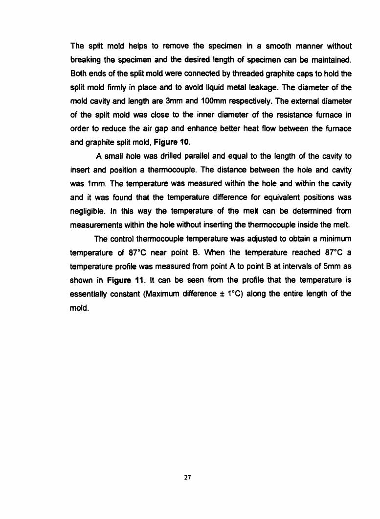
The split mold helps to remove the specirnen in a smooth manner without
breaking the specimen and the desired length of specimen can be maintained.
60th ends of the split mold were connected by threaded graphite caps to hold the
split mold firmly in place and to avoid liquid metal leakage. The diameter of the
mold cavity and length are 3mm and 1OOmm respectively. The extemal diameter
of the split rnokl was close to the inner diameter of the resistance furnace in
order to reduce the air gap and enhance better heat flow between the furnace
and graphite split mold, Figure 10.
A small hole was drilled parallel and equal to the length of the cavity to
insert and position a thennocouple. The distance between the hole and cavity
was Imm. The temperature was measured within the hole and within the cavity
and it was found that the temperature difference for equivalent positions was
negligible. In this way the temperature of the melt can be detemined from
measurements within the hole without inserting the thennocouple inside the melt.
The control therrnocouple temperature was adjusted to obtain a minimum
temperature of 87'C near point B. When the temperature reached 87°C a
temperature profile was measured from point A to point B at intervals of 5mm as
shown in Figure 11. It can be seen from the profile that the temperature is
essentially constant (Maximum difference i 1°C) along the entire length of the
mold.

Figure 9 : Photograph of graphite split mold.

I BLOCKED END OF MOLD
THERMOCOUPLE HOLE
SPLIT MOLD
MOLD CAVITY
CONTROC TC
.. .-. . ... . . ...
.. ......'... *;*...,,* ...
THREADED CAP OPEN END
Figure 10 : Schematic diagram of resistance fumace for static casting in graphite mold.

... --.
MOLD CAVITY HOLE l
SPLIT MOLD
LENGTH (mm)
Figure 11 : Temperature profile inside the mold cavity.
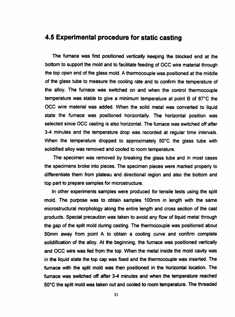
4.5 Experimental procedure for static casting
The fumace was first positioned vertically keeping the blocked end at the
bottom to support the mold and to facilitate feeding of OCC wire material through
the top open end of the glass rnold. A themocouple was positioned at the middle
of the glass tube to measure the cooling rate and to confinn the temperature of
the alloy. The furnace was switched on and when the control thermocouple
temperature was stable to give a minimum temperature at point 6 of 87'C the
OCC wire material was added. When the solid metal was converted to liquid
state the furnace was positioned horizontally. The horizontal position was
selected since OCC casting is also horizontal. The furnace was switched off after
3-4 minutes and the temperature drop was recorded at regular time intervals.
When the temperature dropped to approximately 50°C the glass tube with
solidified alloy was removed and cooled to room temperature.
The specimen was removed by breaking the glass tube and in most cases
the specimens broke into pieces. The specimen pieces were marked properly to
differentiate them from plateau and directional region and also the bottom and
top part to prepare samples for microstructure.
In other experiments samples were produced for tensile tests using the split
mold. The purpose was to obtain samples 1OOmm in length with the same
microstructural morphology along the entire length and cross section of the cast
products. Special precaution was taken to avoid any flow of liquid metal through
the gap of the split mold during casting. The themocouple was positioned about
50mm away from point A to obtain a cooling curve and confinn complete
solidification of the alloy. At the beginning, the furnace was positioned vertically
and OCC wire was fed from the top. When the metal inside the mold cavity was
in the liquid state the top cap was fixed and the thermocouple was inserted. The
furnace with the split mold was then positioned in the horizontal location. The
furnace was switched off aRer 3-4 minutes and when the temperature reached
50°C the split mold was taken out and cooled to room temperature. The threaded

caps from both ends of the mold were opened and the cast sample removed. Ali
sarnples produced were stored in a cardboard socket to prevent buckling and
bending that could cause centering problems during machining.
4.6 Sample grip design for mechanical testing
INSTRON machine, mode1 8501, with ASTM specification k 1 % was used
for the tensile test to compare the ductiiity of the OCC and statically cast
specimens. A photograph of the machine is shown in Figure 12. The machine is
equipped with two grips and can perform tensile or compressive tests under
different controlled conditions.
Problems were encountered with the l NSTRON machine as follows,
a) The grip was flat and to perfon tensile tests with round samples, the area of
contact was from two points as shown in Figure 13 A. Due to insufficient area of
contact, the specimen would slip and the data on elongation % was wrong.
b) The grip was designed to operate with a high hydraulic pressure. The high
impact and the compressive force deforrned the specimen at the grip area. It was
found that OCC samples became thin strip at the grip area as described in
Figure 138 and static samples originated cracks around the surface and were
deformed in the grip area as shown in Figure 13C. The result was premature
failure in the deformed area and not inside the gauge length and again the data
from testing was wrong.
c) For a tensile test it is important to align samples along the stress axis
otherwise the test could give wrong information. With the INSTRON machine the
problem was that there was no proper marking on the grip to align the sample
along the stress axis.

Figure 12 : Photograph of INSTRON machine, mode1 8501.

Two point pressure on ( ) a round specirnen
A) Specirnen in INSTRON flat grip without pressure
Ductile specimen
1
6) OCC -*men at grip area plastically defmed after pressure
C) Static specimen at grip area deforrned and cracked
Figure 13 : Schematic diagram showing the problem associateci with INSTRON high pressure and flat gnp


To eliminate these problems a special grip was designed as shown in
Figure 14. Two pairs of low carbon steel plate with dimensions 3mm thick, 41mm
width and 56mm length were machined. The dimensions were important to
position each pair of modified grips between the lower and upper grip of the
INSTRON machine to avoid play inside the INSTRON grip. A "V" shaped right-
angled groove was cut at the center of each plate along the length to position
samples perfectly along the stress axis. The "V" shape was selected to obtain the
cross-sectional shape of a square after assembling two plates. The distance
between the two sides of the square was calculated to be exactly equal to the
diameter of the specimen. In this way the holder groove touches the specimen
from four points as shown in Figure 15 a. This helps to maximize the contact
area and slipping during the tensile test can be avoided. Again the hydraulic
pressure of the INSTRON grip was resisted by the rnodified low carbon steel
grips.
To carvout experiments with samples of different diameter, it was
necessary to prepare holders with different dimensions of the right-angled "V
shaped groove. If the diameter of the specimen is "2X, then the depth and width
of the groove can be calculated from Figure 15 b and is shown in tabulated form
in Table 1.
Table 1 : Mathematical expression to obtain the dimension of the groove of the
modified grip according to diameter of the sample
Diorneter of sample :
Depth of the groove Width of the groove

INSTRON flat gflp
Modified grip Specirnen
a) A transverse sedion of modified gnp showing the four point contact and resistance to high pressure from INSTRON machine
Diameter of specimen - 2X, Height of the groove - X 4 2. Wdai of the gmove - 2X 4 2
b) Dimension of rnodified grip groove according to the diarneter of the specimen
Figure 15 : Schematic diagram of modified grip.

4.7 Sample preparation for tensile test
The wire produced by OCC has good surface finish and during machining
there was no problern associated with centering of the specimen and to obtain a
constant gauge diameter. In contrast the surface of the staticalîy cast product
was not smooth. The surface quality can be distinguished from the photograph in
Figure 16. The surface of the statically cast product has blowholes from
entrapped gas and ridges which originated from the gap between the splits.
These specimens were machined until the surface was smooth enough along the
gauge length to eliminate surface defects. The depth of shrinkage cavities varied
from sample to sample.
The static cast product was prone to breaking if the depth of cut exceeded
a certain critical value per pass. The depth of cut per pass was fixed within the
range 0.i mm to 0.1 5mrn per pass and this helped to avoid not only breaking but
also buckling and deflection of the samples. For OCC samples there was no
problem with surface defects or breaking of samples. To maintain the same
surface condition after machining, the same depth of cut per pass was
maintained. For both static and OCC samples special precaution was taken to
avoid any rise in temperature for the low melting point alloy by ensuring sufficient
fiow of cutting fluid.

a) OCC wire without surface defect
b) Statically cast rod with surface defect
Figure 16 : Photograph of OCC wire and statically cast products showing
significant difference in surface quality.
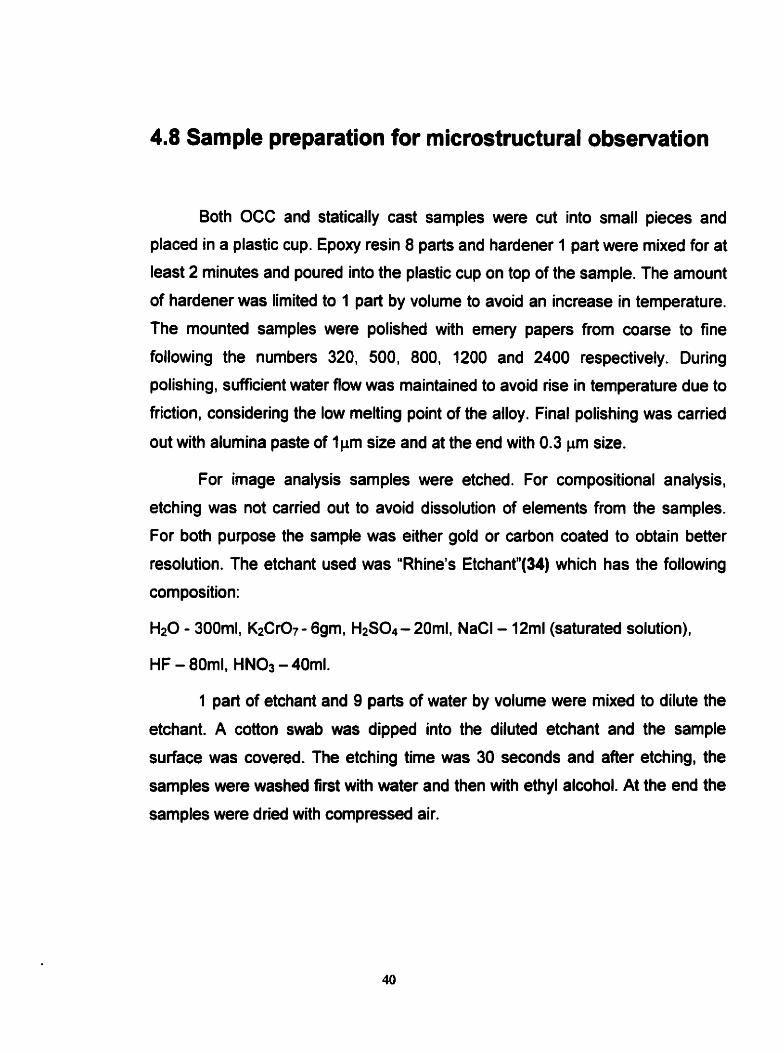
4.8 Sample preparation for microstructural observation
Both OCC and statically cast samples were cut into small pieces and
placed in a plastic cup. Epoxy resin 8 parts and hardener 1 part were mixed for at
least 2 minutes and poured into the plastic cup on top of the sample. The amount
of hardener was limited to 1 part by volume to avoid an increase in temperature.
The mounted samples were polished with emery papers from coane to fine
following the numbers 320, 500, 800, 1200 and 2400 respectively. During
polishing, sufficient water fiow was maintained to avoid rise in temperature due to
friction, considering the low melting point of the alloy. Final polishing was carried
out with alumina paste of lpm size and at the end with 0.3 pm size.
For image analysis samples were etched. For compositional analysis,
etching was not canied out to avoid dissolution of elements from the samples.
For both purpose the sample was either gold or carbon coated to obtain better
resolution. The etchant used was "Rhine's Etchantt'(34) which has the following
composition:
Hz0 - 300ml. K2Cr07 - 6gm, H2s0.1- 201111, NaCl - 12ml (saturated solution),
1 part of etchant and 9 parts of water by volume were mixed to dilute the
etchant. A cotton swab was dipped into the diluted etchant and the sample
surface was covered. The etching time was 30 seconds and after etching, the
samples were washed first with water and then with ethyl alcohol. At the end the
samples were dried with compressed air.

CHAPTER 5
RESULTS AND DISCUSSION
5.1 Evaluation of casting condition for OCC
5.1.1 The occurrence of breakout
Experiments were conducted at different casting speeds to determine the
most suitable casting condition for Bi-ln-Sn ternary eutectic alloy (Melting point
77°C). The purpose was to avoid run out of liquid metal outside the mold exit
during conünuous casting.
In the OCC process the mold temperature is kept above the melting point
of the metal to be cast and therefore solidification does not occur inside the mold.
The liquid metal is cooled by water in front of the mold exit and heat is extracted
through the cast strand. Thus solidification occurs between the mold exit and
water cooler. The liquid rnetal outside the mold exit is a floating zone held in
place by surface tension. Breakout occurs when the volume of the liquid rnetal
overcomes the surface tension. In addition to the surface tension, the volume of
the floating zone is influenced by several factors like water-cooler distance, flow
rate, casting speed, mold exit temperature, height of the metal head and cross-
sectional area of the products.
In the experimental procedure some controlling factors which influence
breakout were kept constant. The melt temperature at the channel entrance was
kept constant at 87'C and the height of the metal head was kept 6mm maximum
from the top of the mold channel for al1 casting speeds. The purpose was to
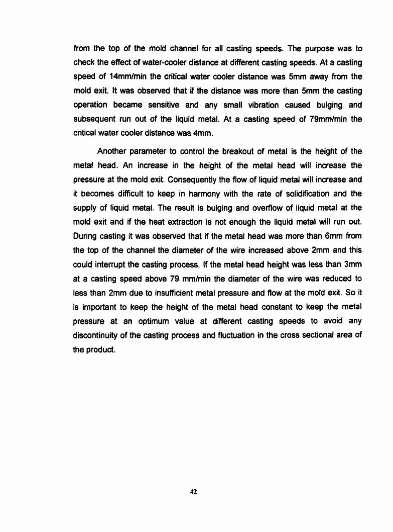
check the effed of water-cooler distance at different casting speeds. At a casting
speed of 14mmlmin the critical water cooler distance was 5mm away from the
mold exit. It was observed that if the distance was more than 5mm the casting
operation became sensitive and any small vibration caused bulging and
subsequent run out of the liquid metal. At a casting speed of 79mmlmin the
critical water cooler distance was 4mm.
Another parameter to control the breakout of metal is the height of the
metal head. An increase in the height of the metal head will increase the
pressure at the mold exit. Consequently the flow of liquid metal will increase and
it becomes difficult to keep in hanony with the rate of solidification and the
supply of liquid metal. The result is bulging and ovefflow of liquid metal at the
mold exit and if the heat extraction is not enough the liquid metal will run out.
During casting it was obsenred that if the metal head was more than 6mm from
the top of the channel the diameter of the wire increased above 2mrn and this
could interrupt the casting process. If the metal head height was less than 3mm
at a casting speed above 79 mmlmin the diameter of the wire was reduced to
less than 2mm due to insuffcient metal pressure and Row at the mold exit. So it
is important to keep the height of the metal head constant to keep the metal
pressure at an optimum value at different casting speeds to avoid any
discontinuity of the casting process and fluctuation in the cross sectional area of
the product.

5.1.2 Surface appearance of cast wire
In the present work the bismuth content of the eutectic alloy was 57.2%.
There are problems associated with high bismuth content, one is the alloy
becomes brittle in nature and the other is the alloy becornes a poor conductor of
heat. McCorrnack et al (16) discussed the severe strain rate dependant
embrittlement of the Bi-Sn solder due to the presence of bismuth rich phases.
Special precaution was taken during the present work to avoid mold strand
friction by avoiding solidification inside the mold. The solid-liquid interface
position can be controlled outside the mokl exit by positioning the water cooler
distance and controlling the mold exit temperature (35.36 and 37). If the water
cooler distance is too short the heat extraction will be high enough to shift the
interface inside the mold. If the water cooler distance is kept constant and the
mold exit temperature is below the critical temperature for a particular constant
casting speed, solidification will occur inside the mold. Under some conditions if
solidification starts well inside the mold, the frictional force between mold wall
and the cast strand will cause rough surface and if the frictional force is
excessive the casting operation will be interrupted.
In the present study the moldçhannel entrance temperature was
maintained at 87"C, water fiow rate at 15Omllmin and feed rate was controlled to
keep the metal head below 6mm. The different surface appearance was
observed by varying the mold-cooler distance. At a casting speed of 14mm/min
when the mold-cooler distance was below the critical distance of 5mm, it was
observed that the surface of the wire was not smooth and breakout occurred due
to friction between the mold wall and cast strand. Again at a casting speed of
79mm/min, when the mold-cooler distance was below the critical distance of
4mm, the same phenornenon was obseived. An attempt was made to cast at
145mmfmin but the critical mold-cooler distance was then below 2mm and the
inconsistent overllow of water was nearly touching the mold exit. The result was
43

a temperature drop at the mold exit and solidification inside the mold. The critical
casting parameters are indicated in Table 2 for different casting speeds.
In initial experiments, the appearance of ridges at regular intervals on the
cast surface was observed. The reason for this was mechanical vibration from
the pinch rollers that caused disturbance at the solid-liquid interface. Other
problems associated with mechanical vibration were a wavy appearance of the
wire and a lack of straightness. lt was found that the pinch rolls were not aligned
properly and this created an up and down movement of the wire and
consequently on the liquid metal at the mokl exit. The result was production of a
wavy surface. To avoid this the pinch rollers were aligned properly, the wire in
between was pressed firmly under load and passed through a glass tube fixed
with a clamp against a horizontal platform.
With the casting conditions shown in Table 2, the OCC wire produced had
a smooth surface finish with no trace of casting defects.
Table 2 : Optimum casting conditions for Bi-ln-Sn alloy
/ Cooling wsbr flow rate (mllrnin]
Temperature at mold
channel enûance ( O C ) -
Water-cooler distance
1 From mold exit (mm)
Casting speed
14mmlmin.
Casting speed
79mm/min.
Casting speed
14Smmlmin.

5.2 Microstructure
5.2.1 Microstructure of static cast rod
From the temperature profile of the glass tube in Figure 8 it can be seen
that from position A to 60mm the region is a plateau and from 60mm to position B
there is a temperature drop and the region has a temperature gradient. So it was
expected that the microstructure would be different in the two regions. The
samples were selected, one from the center of the plateau region and the other
from the center of the temperature gradient zone. The temperature drop or
cooling curve of the melt in the glass tube was measured, one at the middle of
the plateau region and another at the middle of the temperature gradient reg ion.
The cooling rate was 0.7'CImin for both regions as shown in Figure 17. Frorn the
cooling curve, evidence of a clear plateau region, which is the freezing point
(77.5"C) of the ternary eutectic alloy, can be seen. No inflection temperature
other than 773°C was observed in the cooling curve. This indicates typical
cooling be havior for a eutectic system.
Figure 18 and 19 show the microstructure of static cast rod frorn the
plateau reg ion and tempe rature gradient reg ion respectively . The microstructure
indicates a polycrystalline structure although the composition of the alloy
corresponds to one of the ternary eutectic points in the Bi-ln-Sn system and the
plateau region of the cooling curve is typical of a temary eutectic. There is no
evidence of a regular repetitive arrangement with the intimate mixture of the
constituent phases. It can be seen from the microstructures from both plateau
and gradient region and phase identification through energy dispersive X-ray
analysis (EDX) that the microstructure was composed of several regions of
different phases as shown in Figure 20.


a) Longitudinal section
b) Transverse section
Figure 18 : Backscattered SEM image of sample from the plateau region of cast
product in glass tube showing the phenomenon of segregated blocks
and complex regular structure of bismuth (white phase).

a) Longitudinal section
b) Transverse section
Figure 19 : Backscattered SEM image of sample from the temperature
gradient region in glass mold showing directional solidification
and less segregation.

(cl (a Figure 20 : Energy dispersive X-ray (EDX) spectra showîng,
a) Segregated bismuth ,
b) Gray phase composed of bismuth and indium inside mottled region of
bismuth corn plex reg ular structure, c) Black dendrite composed of th with a trace of bismuth,
d) Gray spine phase inside eutecüc cell composed of bismuth, indium and
tin,

The phases identified in the plateau region were eutectic grains, black Sn
rich dendrites, white bismuth blocks and branched white bismuth structure
(corn plex reg ular structure). The growth of dendrites in alloys having eutect ic
compositions may occur due to the presence of a skewed couple zone
(27,30,38). The formation of Bi bearing phases caused extensive segregation.
In many systems the microstructure is not the intimate mixture of the
constituent phases as reported by Ruggiero and Rutter (25). In the temperature
gradient region the microstructure of the longitudinal section, as shown in Figure
19 a, is unidirectional. From both longitudinal and cross-sectional views in Figure
19 a and b respectively. there is very little segregation of the white bismuth
phase. However in the plateau region as shown in Figure 18 a and b, for
longitudinal and cross-sectional area, blocks of white pure bismuth and massive
cornplex regular structure of bismuth have segregated to the bottom part,
compared to the upper part, of the cast rod. Apart from the pure bismuth block,
bismuth is present in different shapes of complex regular structure. The white
bismuth, complex regular structure, was also found around grain boundaries. The
blocks of bismuth was identified by SEM energy dispersive X-ray (EDX) analysis
and it can be seen from Figure 20 a, that the phase is pure bismuth and there is
no trace of other elements. The existence of bismuth blocks as well as complex
regular structure segregated at the bottorn is due to their higher density. It was
found that the density of the ternary eutectic is approximately 8.5 gm/cm3
compared to that of bismuth 9.8 gmlcm3. In contrast, in the temperature gradient
region the complex structure of bismuth is along the directionally solidified
eutedic grains and the amount of segregation at the bottom is negligible. The
phenomenon of segregation has been reported for a Sn-Pb alloy (30) eutecüc
composition where Pb primary dendrites segregated at the bottom and the Sn
rich dendrites segregated at the top due to the phenomenon of difference in
density of the pn'mary phase compared to the bulk liquid. Pb had higher density
than the bulk liquid and hence segregated at the bottom and Sn had lower
density than the bulk liquid and floated to the top. This type of phenomenon gives
rise to compositional variation from top to bottom of cast products and in the final

microstructure a mixture of different phases can be found rather than the eutectic
composition. Large complex structures of Bi were observed mostly in the
temperature plateau region where the growth is not directional.
An enlarged portion of the eutectic grain of the plateau region in Figure 21
shows a tin rich black lamellar area with a trace of bismuth white phase, a spine
shaped gray matrix, mottled region of Sn rich dendrite and white bismuth
corn plex regular structure segregated around the grain boundary. The gray
matrix of the eutectic cell was identified through EDX analysis as shown in
Figure 20d, and al1 three elements, Bi, In and Sn were present. Even in the
temperature gradient region the small cornplex regular structures have
segregated along grain boundaries. The complex regular structure is the result of
the ingrowth of the second phase inside bismuth phase and the extent of it
depends on growth rate (20). In the microstructural investigation for bismuth
bearing ternary alloys it has been reported that at the slow growth rate, massive
bismuth is forrned and at faster speed, Bi phase tends to branch out to fom a
skeletal or complex regular structure (23,25). The same phenomenon was
observed by Bagheri and Rutter (20) in Bi-Pb and Bi-Sn binary eutectic systems.
The presence of three types of complex regular structures were observed
in statically cast rod within the plateau region. The three different types of
corn plex reg ular structures can be disting uished from the basic shape of "cubic",
'Yish spinen and "trigonal" as shown in Figures 23 a, b and c respectively.
Baragar et al (39) observed that the different complex regular structures depends
on growth rate and temperature gradient. They plotted growth rate vs.
temperature gradient to show at which different shapes of complex regular
structure in bismuth and lead eutectic alloy occur and found that the shape of the
complex regular structure will change from "fish spinen to "trigonal" to "cubic" with
increasing growth rate. Ruggiero and Rutter (22) found that there is a well-
defined faceted phase in Bi rich areas and to a lesser extent in the Bi-ln phase.
Hunt and Jackson (18) predicted on the basis of smooth atomic attachent at
the solid-liquid interface that if one of the phases grows as faceted, the formation
of complex regular structures should exist. Hunt and Hurle (40) stated that the

lateral movement of complex regular growth occurs along a crystallographic
plane where there should be no formation of new solid layer on an existing solid
in the presence of an energy barrier. Also Bagheri and Rutter (20) suggested that
the branching of Bi phase is due to the ingrowth of the second phase inside the
Bi faceted phase.
From Figure 23 it can be observed that inside skeletal Bi structure there
exist mottled regions. In Figure 23 c it is clear that inside skeletal bismuth the
mottled region is composed of a black and gray phase. The same mottled region
can be seen in Figure 21 in the dark dendritic region but white Bi particles are
also present. The gray phase of the rnottled region in both cases was checked
through EDX analysis as shown in Figure 20 b and it can be observed that there
is no trace of Sn phase. The black phase in the mottled region is composed of Sn
with a trace of Bi as shown in the EDX analysis in Figure 20c. The overall
composition of the rnottled region in both Figure 21 and 23 c as identifieci in the
EDX analysis in Figure 22 is identical to that reported by Ruggiero and Rutter
(24). From the phase diagram in Figure 4 it can be seen that at the ternary
eutectic temperature the tin phase should be y-Sn. From the prediction of
Ruggiero and Rutter (24) it can be suggested that pSn eventually decomposes
into p-Sn, Biln and Bi phases due to the ternary eutectoid reaction and for this
reason the mottled appearanœ of the Sn dendrites can be observed. The black
phase in the mottled region is the p-Sn phase with a trace of bismuth and the
grey phase is Biln without a trace of tin. f he solid state eutectoid reaction within
the y-Sn dendrites has occurred at different nucleation sites resulting in the
formation of irregular lamellar structure, temed "mottled" region. It can be
observed that when the structure is massive it exhibits a mottled structure and
consists of three phases (Sn, Biln and Bi). But as can be seen from an enlarged
microstructure of eutectic grain Figure 24, in some areas where the black phase
is narrow, the gray phase is absent. From Figures 21 and 24 it can be seen that
in some portions the mottled region is absent where the interphase region has
less spacing, or the microstructure is fine in that particular phase. To investigate
52

the eutectoid reaction and the branching of Bi, samples were produced by static
casting in a graphite mold at different cooling rates keeping al1 other conditions
the same. The cooling rate was maintained at 09"Clmin, O.S°Clmin, I0C/min and
2"CImin. Figure 25 and Figure 26 show the microstructures observed at
different cooling rates. It can be seen that there is no signifiant difference in
microstructure in the cooling rate range of O.S°C/min to 2"Clmin. At al1 cooling
rates it can be seen that Bi is in cornplex regular fom except in the
microstructure in Figure 25 a where it can be observed that Bi is almost block
shape when the cooling rate was Oî°Clmin. It can be concluded that at lower
cooling rates the branching out tendency of Bi can be minimized which has a
direct effect on minimizing growth rate. Advantage was taken of coarse grains at
the slowest cooling rate to investigate the occurrence of eutectoid reaction in the
primary Sn-dendrites. It can be seen from Figure 27 that the Sn-dendrites
consist of several colonies or cells having lamellar microstructure. The lamellar
microstructure in the dendrites is a clear indication of eutectoid reaction and that
each colony has grown from an individual nucleation event. It can be concluded
that when the interphase spacing is larger, the eutectoid reaction can be
confirmed by the mottled appearance with the presence of three phases Sn, Bi
and Biln. When the interphase spacing is narrow the mottled appearance
disappears and a binary structure of Sn and Bi with a regular spacing with Biln
occurs. Hence it can be suggested that when the interphase spacing is narrow
the Biln phase is incorporated into the matrix (Biln). This type of phenomenon
can be predicted when the cooling rate is faster and the microstructure is fine,
creating a narrow interspacing.
According to the findings of Ruggiero and Rutter (24) and from the
observations from the present experiments, 1 can be concluded that there exists
regions of double binary microstructure rather than temary eutectic structure
which represents the repetitive arrangement of three phases (41). In the case of
Bi-Cd-Sn system it has been observed that the Cd and P Cd-Sn phases fonned a
nearly regular binary lamellar microstructure containing coane Bi structure (25).
In general it can be seen that in the Bi-ln-Sn system double binary structures

exist in the form of Biln-ySn and Bi-ySn. ySn has the decomposed structure which
has tetragonal PSn, Biln and Bi. lnside the complex regular structure of Bi-ySn
the mottled microstnidure consists of gray Biln and black pure Sn without any
trace of Bi inside the pSn phase. The eutectic grains consist of a binary structure
of Biln-ySn where two phases from decomposed y-Sn are present in the fom of
pSn aiong with Bi particles and the other Biln incorporated in matrix represents a
three phase decomposition. The same phenomenon was observed by Ruggiero
and Rutter (24). From this type of microstructure it is reasonable to conclude that
in the case of Bi-ySn, the Bi phase is absent due to the incorporation of Bi phase
into the Bi skeletal structure and in the case of Biln-ySn the Biln phase has
incorporated inside the Biln phase. lt can be concluded that in the present work
for statically cast samples, we have double binary structures of Bi-ySn and Biln-
ySn, segregated blocks of pure bismuth and mottled Sn dendrites. From Figure
21 it can be seen that the eutectic cell (gray, Biln-ySn binary) and complex
regular (white, Bi-ySn binary) can be distinguished from the grain boundary area.
The small complex regular structures were always observed around grain
boundaries whereas the massive complex regular structures were not confined
around grain boundaries as shown in Figure 18.
Evidence of precipitation has been observed in static cast samples inside
the Biln matrix as shown in the back-scattered SEM image in Figure 24 and also
in Figures 25 and 26 where the samples were produced at different cooling
rates. It can be observed that Bi and Sn has precipitated in the Biln matrix which
indicates that at the eutectic temperature, the Biln must have dissolved a certain
amount of Bi and Sn and precipitation occurred during cooling to room
temperature.

Figure 21 : Backscattered SEM image of eutectic cell showing segregated white
bismuth phase in the forrn of complex regular structure around grain
boundary, bismuth-indium gray spine and mottled region of tin
dendrite.

Figure 22 : EDX analysis showing the presence of three elements Bi, Sn and In
in the decornposeci structure of Bi cornplex regular structure.

c) Figure 23 : Backscattered SEM image showing a) the cubic, b) the fish spine
and c) the trigonal shaped cornplex regular structure of bismuth.

Narrow Precipitation inside matrix
tin phase
Wide ti phase
Figure 24 : Backscattered SEM image showing the precipitation of bismuth
and tin in gray rnatrix and absence of gray region where black
tin phase is narrow.

a) Cooling rate 0.2'Clmin
b) Cooling rate O.BoClmin
Figure 25 : Backscattered SEM image of complex regular structure.

a) Cooling rate 1 "Clmin
b) Cooling rate TClmin
Figure 26 : Backscattered SEM image of cornplex regular structure.
60

Figure 27 : Decomposed Sn dendrite showing several colonies or ceils having
larneilar structure.

5.2.2 Microstructure of OCC wire
The back scattered SEM images of OCC wire at a casting speed of
14mm/rnin are shown in Figure 28 a (longitudinal section) and in Figure 28 b
(transverse section). It can be seen from the longitudinal section that the overall
structure is unidirectional. There is no evidence of grain boundaries and the
segregated bismuth blocks or complex regular structure. From the transvene
section, it can be seen that al1 phases are uniformly distributed. A longitudinal
section of OCC wire produced at a casting speed of 79mmtmin is shown in
Figure 29 a and a transverse section in Figure 29 b. It can be seen from the
longitudinal section that the structure is not directional throughout the entire
length. The bottom part is not directional along the casting direction compared to
the upper part. The boundary between the upper part and the lower non-
directional part bas no segregated phase. The transverse image is identical with
that of OCC wire produced at the lower casting speed. The main difference
between OCC wire produced at different speeds is that in the case of higher
casting speed the microstructure is finer. In Figure 28 a) and b) a backacattered
SEM image of the longitudinal and transverse sections of OCC wire produced at
a casting speed of 14rnmlmin at low and high magnification shows mainly three
phases : black dendritic phase, white phase connected to black phase and a
gray matrix. An EDX analysis was carried out to check the elements present in
each phase as shown in the Figure 30. The white phase connected to black
dendrites is pure bismuth, as shown in the EDX analysis in Figure 30 a. The
black phase consists of tin rich dendrites with a trace of bismuth since the
bismuth phase is connected with tin dendrites as shown in Figure 30 b. The gray
phase in the matrix had the composition of bismuth and indium as shown in the
Figure 29 c. It can be seen that the gray matrix phase in the OCC sample has
- only bismuth and indium and no trace of tin. In statically cast sample EDX
analysis confirmed the presence of al1 the three elements, bismuth, indium and
tin in the gray matrix of eutectic ceIl, but tin was absent in the gray mottled region
inside the Bi complex regular structure which is Biln of decornposed structure.
62

There is no trace of small or massive Bi complex regular structure or Bi block
structure in the OCC microstructures but from the EDX analysis of gray rnatrix of
OCC samples it can be observed that bismuth content is higher compared to the
matrix of statically cast samples. The phases in OCC samples are uniformly
distributed and there is no trace of grain boundary at a casting speed of
14mmlmin. At a casting speed of 79mmlmin the structure is directional but one
part is parallel to the casting direction and the other part has a deviation. The
OCC wire structure produced at a casting speed of 79mmlmin was fine and it
was difficult to obtain clear images at lower magnification.
It has been observed that in case of static casting if the interphase
spacing is narrow, we may expect a structure where the binary structure of Biln-
ySn can result in the formation of a final morphology of Sn coupled with Bi in a
matrix of Biln due to the decomposition of ySn. At both casting speeds in OCC
samples it was observed that the Bi phase is coupled with Sn dendrites. It is
suggested that in the case of the OCC process at eutectic temperature the
structure was composed of ySn and matrix of bismuth and indium with higher
content of bismuth compared to statically cast samples. The decomposed
structure of y-Sn could accommodate only Bi and Sn due to the fine
microstructure. The other decomposition product, Bil n, was incorporated within
the matrix of bismuth and indium. When the Biln is incorporated in the matrix, the
morphology of the dendrite structure is different from the original and has a
similarity with the thermally annealed dendrite structure reported in the literature
(19). With OCC samples it can be concluded that the structure is not composed
of a double binary structure like statically cast samples. The ySn dendrites in the
OCC samples have decomposed resulting in the formation of PSn dendrites
coupled with bismuth and the Biln component has been incorporated within the
bismuth-indium matrix. The wire produced at a speed of 14mm/min was coarser
and an enbrged image is shown in Figure 31. The bismuth phase is not in a
complex fom but exists as blocks and is well conneded with tin dendrites,
Figure 31a and b. ln statically cast rod the precipitation of tin and bismuth was

mostly inside the gray region of the eutectic cell. EDX analysis of the gray matrix
confirmed the presence of al1 three elements, bismuth, indium and tin.
Compared with statically cast samples, the OCC samples have the
following features,
a) No segregation of bismuth in the cast samples.
b) No complex regular structure of bismuth, but rather pure bismuth connected
with tin dendrites due to the decornposition of y Sn.
C) NO evidence of double binary structures.
d) Fine and uniform distribution of al1 the phases.

Casting directio
ong itud inal section
'fan sverse section
Figure 28 : Backscattered SEM image of OCC wire, casting speed 14mmlmin.
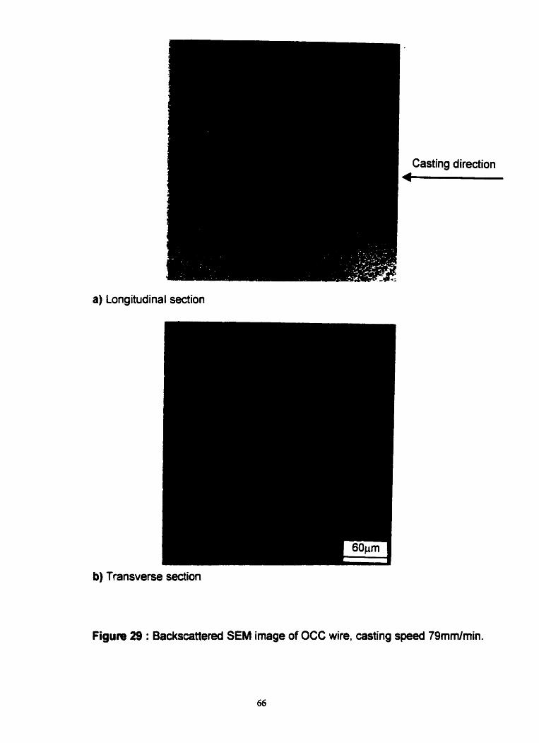
a) Longitudinal section
asting directio
b) Transverse section
Figure 29 : Backscattered SEM image of OCC wire, casting speed 79rnm/min.

(cl Figure 30 : EDX spedra of OCC wire showïng,
a) White pure bismuth phase. b) Bbck dendritic tin phase,
c) Gray matrix phase without lin.

A Casting direction
a) Low magnification
b) High rnagnification
asting directio
Figure 31 : Backscattered SEM image of OCC wire, casting speed 14mmlmin,
showing a) tin dendrite and associated bismuth and b) at higher
magnification.

5.3 Compositional unifonnity in OCC samples
In statically cast products it can be seen from the SEM back scattered image
that the structure is coarse. From the structure, even at low magnification, it can
be observed that in the lower part of the cast product, the volume of segregated
white bismuth phase is more than in the upper part. The black tin dendritic
structures are distributed at random. If EDX analysis is performed at different
areas, differences in chemical composition will be observed between the upper
and lower part of the cast sample. For example, an EDX analysis of the lower
area will show significantly higher amounts of bismuth compared to the upper or
middle parts of the cast product. This indicates that for statically cast product, the
phases as well as chemical composition are not uniform.
Compared to statically cast product, OCC wire has some different features,
fine microstructure, nearly unidirectional solidification and no trace of segregation
and the phases were uniformly distributed. Although the phases were uniformly
distributed in OCC samples it was still necessary to establish the unifomity of
chemical composition at different areas of a longitudinal section. To check this,
OCC wire of 130cm in length was produced at a casting speed of 79mmhin
from one melt. The wire was cut into 13 equal pieces from start of casting to the
end of casting. Each piece or sample was polished and was prepared for EDX
analysis without etching to avoid any dissolution of a particular phase.
This is important to mention that in the present study the alloy prepared from
bismuth, indium and tin have a weight % of 57.2, 24.8 and 18 respectively.
Neutron activation analysis of a quenched sample in "Slow Poke Reador" was
conducted and to investigate a quenched sample of the alloy prepared. It was
found that the wt % of bismuth, indium and tin was 57.2, 25 and 17.8
respectively. But the result of the EDX analysis of the same quenched sample in
wt % was 51.6 % bismuth, 21.77 % indium and 26.63 % of tin. The atomic
number of indium and bismuth is 49 and 50 respectively. This irnplies that error
may occur during EDX compositional analysis of these two elements due to their
69

nearly same energy level. So the difference of actual ternary eutectic
composition and EDX result was rneasured and was added or subtracted with
the composition obtained for each element of OCC sample.
At first the weight % of bismuth, indium and tin from top and bottom areas of
the longitudinal section was measured for one sample. lt was found that in a
single sample there was no large deviation in percentage of each element from
the average weight % of individual elements measured at different locations
within the same sample.
In the next step, the purpose was to check the uniforrnity in chemical
composition, from start of casting to the end of casting and compare the
difference in wt % from the average values. The chemical composition of each
piece from different locations was measured in weight %. The average weight %
of each element was calculated from the data obtained from 13 samples. The
average reading was considered as a reference and the difference in weight %
for each element from the average value was measured as shown in Table 3. A
plot was made to describe the difference in weight % as a function of length of
sample from start of casting, Figure 32. It can be observed that the difference in
weight % from average value for bismuth, indium and tin are approxirnately 12,
11.5 and il respectively. This indicates that OCC samples have nearly uniforrn
composition.
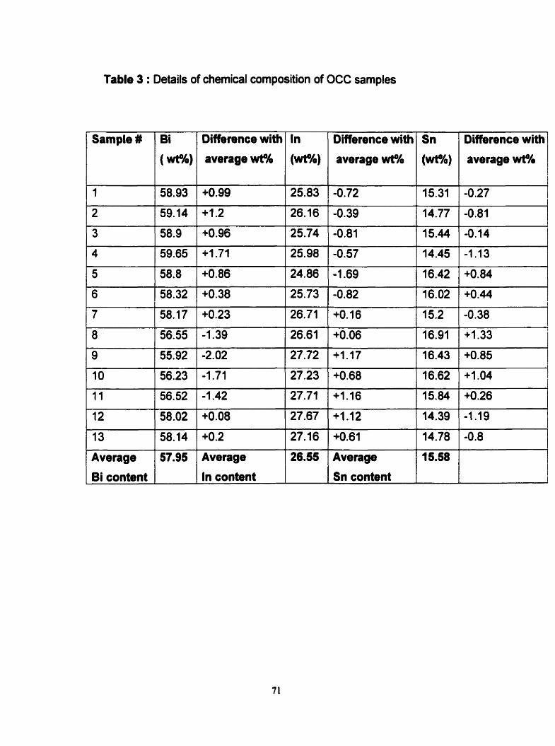
Table 3 : Details of chemical composition of OCC samples
+O36 25.74
+1.71 25.98
+0.86 24.86
+0*38 25.73
+0.23 26.71
-1.39 26.61
-2.02 27.72
-1.71 27.23
-1.42 27.71
+0.08 27.67
+0.2 27.16
Average 26.55
In content
Difference with
average wt3C
58.14
Bi content
Avenge
Sn content
In
(wtlt)
Difference with
average wt16
Sn
(wtlb)
Difference with
average wt?h
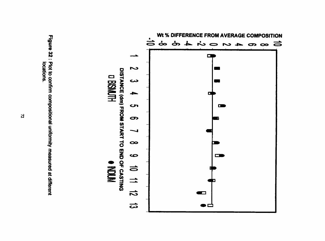
Wt % DIFFERENCE FROM AVERAGE COMPOSITION 4 d
O & & & L O r u P C J 3 O o O

5.4 Mechanical properties
It has been observed that there are differences in structural morphology
between statically cast and OCC products. In general the statically cast products
are multicrystalline, consisting of coarse microstructure and the bismuth phase is
segregated along grain boundaries in the forrn of complex regular structure and
segregated at the bottorn due to gravit-. The matrix, which is composed of
bismuth and indium, has a lot of precipitation of bismuth and tin. In OCC, the
structure is nearly unidirectional with a tin dendrite structure in a matrix of
bismuth and indium and the phases are uniformly distributed. The bismuth phase
is closely associated with tin dendrites in the OCC products. The gray matrix has
no trace Bi phase in the form of complex regular structures or blocks. The Bi
content within the matrix is higher than in the static cast samples. Shewmon (13)
discussed the cause of embrittlement in gold alloys. He concluded that only 0.2
wt % bismuth addition in gold significantly lowered the elongation and ultimate
tensile strength of the alloy due to low solid solubility in the matrix and also the
inability to form intenetallic compounds. However in OCC samples, Bi has not
segregated and this is in accord with the high bismuth content of the matrix
cornpared to the statically cast samples.
The purpose for mechanical testing was to check the effect of rnicrostructural
change on mechanical behavior and to compare toughness as well as strength
between OCC and statically cast samples. A series of tensile tests at different
crosshead speeds were conduded using an INSTRON machine. The minimum
total length of the sample required was approximately 1OOmm.
All the statically cast samples for mechanical testing were produced with the
split mold at a cooling rate of about 0.8"CImin and the reference thennocouple
temperature was adjusted to follow a temperature profile as shown in Figure 11.
Samples from d ifferent locations of the cast rod were prepared for microstructure
observation and it was confimed that there was no difference in microstrudural
morphology. A back-scattered SEM image, Figure 33,represents the general
structure of the sample. It can be seen that bismuth blocks have segregated at 73

the bottom of the cast rod. The black phase represents tin rich dendrites. The
eutectic grains were surrounded by bismuth complex regular structure. The grey
matrix phase contains bismuth and indium.
The tensile specimens as shown in Figure 34, both from OCC and static
casting, were machined to a gauge length of 25mm. The as cast statically cast
rod products have a diameter of 3mrn and cast defects such as blow holes and
ridges were present at the surface along the entire length. To remove surface
defects it was necessary to machine out nearly imrn of thickness and the gauge
diameter was then around 2mm. In this way the segregated bismuth phase was
removed during machining. It is important to mention that the bismuth phase is
brittle in nature and the presence of segregated bismuth at the surface could
initiate cracks. Subsequent crack propagation could initiate stress concentration
at the crack tip resulting in transgranular or brittle fracture.
Surface condition is important in terms of strength, since the presence of
notch on surface increases the stress concentration at the tip of the notch and
fracture occurs at lower applied stress. In the case of OCC samples, produced at
a casting speed of 78mmlmin the surface was shiny indicating no surface
defects. However the samples were machined under identical conditions to the
static cast samples in order to have the same surface appearance and condition
after machining.
It was observed that during machining the surface rnaterial of statically
cast samples came out in the form of chips or small particles and for OCC
samples the surface material was in the shape of continuous turnings as shown
in Figure 35. The small particle or chip shape is a good indication of brittleness
and the continuous turnings indicate ductility. Again the static samples fractured
if the depth of cutting exceeded 0.1 5mm per pass. This was not the case with
OCC wire. The shape of the chips and limitation of the depth of cut indicates the
low energy of statically cast products compared to OCC wire. Mechanical testing
was carried out for both staüc and OCC samples at different crosshead speeds
to check the extent of strain sensitivity. The crosshead speed was selected at
i.25mmlmin. 2.5mmlmin, 5mmhnin, 7.5rnmlmin and 1 Ommlmin and kept

constant until fracture occurred. The initial strain rate was calculated from the
crosshead speed. Frorn this test a plot of stress vs. elongation % was obtained at
different crosshead speeds. The crosshead speed and the corresponding initial
strain rate have been tabulated in Table 4. The terni initial strain rate is the ratio
of crosshead displacement in mmlsecond and initial gauge length in mm.
Table 4 : Relation between crosshead speed and initial strain rate
CROSS-HEAD SPEED (MMIMIN) 1 INITIAL STRAIN RATE ( SEC*')

Figure 33 : Backscattered SEM image of statically cast rod accepted
for tensile test. Segregated bismuth was removed by machining
during sample preparation.
Gauge diameter I
Gauge length = 25 mm
Figure 34 : Schematic diagram of tensile specimen
76

OCC
Static
Figure 35 : Photograph of tumings to show difference in material properties between OCC and statically cast samples.

The tensile tests were conducted at room temperature (25°C). For a particular
crosshead speed the tensile test was conducted for three OCC samples and
three statically cast samples. At a particular crosshead speed for both types of
samples maximum and minimum values of stress and elongation % were
observed. Comparative plots of stress vs. elongation % at different crosshead
speeds were prepared for each sample, Figure 36 to Figure 40.
At crosshead speeds from 1.25mm/min to 10mmlmin the OCC samples
have an elongation value within the range 3560% of initial gauge length. In the
statically cast products the range was 2243% at crosshead speeds from
1.25mmlmin to Smmlmin and the maximum and minimum elongation observed at
a crosshead speed of 7.5mmlmin was approximately 20% and 1% respectively.
At the maximum crosshead speed of 10mmlmin the statically cast product had
no trace of plastic deformation. This indicates that statically cast samples had
inconsistency in terms of elongation or ductility. The consistent range of
elongation at different crosshead speeds for OCC samples indicates that this
material is not strain rate sensitive in contrast to static cast samples.
The values of yield stress (0.2% off set), UTS and maximum elongation for
each set of samples at different crosshead speeds were determined and the
details for each sample are shown in Table 5 for statically cast samples and in
Table 6 for OCC samples.

OCC Static
a) Maximum elongation values
OCC Static
b) Minimum elongation values
Figure 36 : Comparison of elongation values between OCC and statically cast samples at a crosshead speed of 1 -25mmlmin.
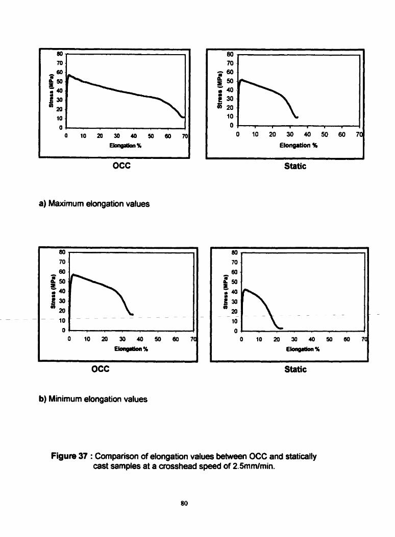
OCC
a) Maximum elongation values
-
OCC
b) Minimum elongation values
Static
Static
Figure 37 : ComparÎson of elongation values between OCC and statically cast samples at a crosshead speed of 2.5mmlmin.

OCC
a) Maximum elongation values
OCC
b) Minimum elongation values
Static
Figure 38 : Cornparison of elongation values betwean OCC and statically cast samples at a crosshead speed of Smmlmin.

OCC Static
a) Maximum elongation values
OCC
b) Minimum elongation values
Static
Figure 39 : Cornparison of elongation values between OCC and statically cast samples at a crosshead speed of 7Smmlrnin.

O 10 20 30 40 50 ôû
Elongation %
OCC
a) Maximum elongation values
O 10 20 30 40 50 60
Elongation %
OCC
b) Minimum elongation values
Static
O 10 20 30 40 50 60
Elongation %
Figure 46 : Cornparison of elongation values between OCC and statically cast samples at a crosshead speed of IOmrnfmin.

Table 5: Mechanical properües of statically cast samples
" - Premature failure. CHS - Crosshead speed, RA - Reduction in area after
fracture, YS - Yield stress, UTS - Ultimate tensile strength

Table 6: Mechanical properties of OCC samples
1 Sample ( CHS (mmlmin) 1 YS (MPa) 1 UTS (MP~)/ RA % 1 ELONGATION %
CHS - Crosshead speed, RA - Reduction in area after ftacture, YS - Yield
stress, UTS - Ultimate tensile strength

A distribution of yield stress, ultimate tensile strength and elongation with
increasing crosshead speed is show in Figures 41,42 and 43 respectively.
The yield stress is the stress at which a specific measurable plastic
deformation, cornmonly 0.2 % plastic strain has taken place. The yield stress of a
given alloy depends on the microstructure, test temperature and strain rate. In
the present work the test temperature and strain rate in ternis of crosshead
displacernent were kept constant for both OCC and statically cast samples.
From the plot of yield stress vs. crosshead speed shown in Figure 41, it
can be observed that for OCC samples the values of yield stress at all crosshead
speeds are consistent in contrast to the behavior observed with specirnens which
had been statically cast. In the case of statically cast product large differences
between maximum and minimum yield stress values at crosshead speeds of
7.5mmlmin and lOmmlmin can be observed. The minimum value of yield stress
has a large deviation from the average value. This indicates that the samples had
premature failure either without, or with only a small amount of plastic strain. The
small areas under the stress-strain curves clearly indicate the low energy for
fracture that is consistent with brittle behavior and indicates the low toughness of
the statically cast samples. In OCC samples the deviation between maximum
and minimum yield stress at al1 crosshead speeds is less and there is an almost
linear relationship between yield stress and crosshead speed. These results
indicate that even at high crosshead speed beyond Srnmimin, OCC samples
have no indication of premature failure.
In the case of OCC samples there exists no deaease in yield stress but
in statically cast samples the yield stress drastically decreases with the increase
in crosshead speed due to premature failure. Beyond a crosshead speed of
Smmlmin, most of the samples showed a premature failure, which indicates that
the statically cast samples, are unable to withstand the stress beyond a
crosshead spaed of Smm/min. This implies that with the test temperature and
constant strain rate the reason for higher toughness observed with OCC samples
is the result of fine microstructure and uniform distribution of al1 the phases.

In Figure 42 it can be seen that the statically cast products not only have
a large difference between maximum and minimum values of ultimate tensiie
strength, but the UTS also decreases as the crosshead speed increases. This
implies that the lower values of UTS for statically cast samples at high strain
rates are not tnie UTS but rather correspond to maximum stress before
catastrophic failure which is very low compared to OCC samples. In the case of
OCC samples the deviation is much less compared to the static samples and
there is no evidence of premature failure. It is evident that the statically cast
sarnples are strain sensitive in contrast to the OCC samples.
In Figure 43 the plot of elongation vs. crosshead speed shows that OCC
samples have a higher elongation compared to static samples. At higher
crosshead speeds the statically cast products have very low elongation and at
10mmlmin there is practically no elongation due to premature failure. High
elongation indicates high ductility and in this context OCC samples have superior
characteristic compared to statically cast samples.
It can be seen from these graphs that in terms of yield stress and ultimate
tensile strength, OCC products have higher values over a wide range of strain
rates. The elongation of OCC wire in general has a higher range of values at low
to high strain rates. This confimis that OCC material has a higher ductility and
toughness than statically cast products due to the improved structural
morp holog y.

O 1.2s 2 5 3.76 6 6.26 7.6 0.76 10 11.2s 125
CROSSHEM SPEED ( mm l min ) I OCC - - - - - STATlCALLY CAST SAMPLE
Figure 41 : Plot of yield stress vs. crosshead speed showing the low value of yield stress at higher aosshead speeds which produces prernature failure of the staticaîly cast sarnples and aie high and consistent yield stress values of OCC samples.

Figure 42 : Plot of ultimate tensile stress vs. ciosshead speed showing, a) significant inconsistency in UTS for statically cast samples at higher crosshead speed and b) higher and more consistent UTS of OCC sarnples.
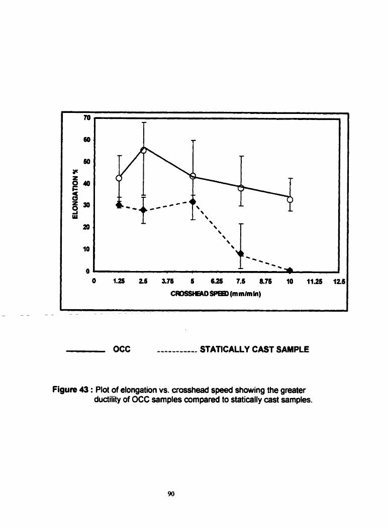
OCC
Figure 43 : Plot of elongation vs. crosshead speed sttowing the greater duaility of OCC samples cornpared to statically cast samples.

5.5 Fracture surface of OCC and statically cast samples
It has been observed from mechanical testing and the data derived in
terms of elongation, yield stress and ultimate tensile stress that the OCC
samples in com parison with statically cast samples have in al1 respects higher
values. At al1 crosshead speeds the OCC samples absorbed a higher amount of
energy in the plastic range, which is the area under the stress-strain curve
indicating the higher toughness compared to statically cast samples. In the case
of statically cast samples, the energy absorbed was significant at lower
crosshead speed, but at higher crosshead speed the energy absorbed was
practically ni1 and failure was catastrophic. To investigate the fracture surface,
both OCC and statically cast samples were identified according to crosshead
speed and examined using SEM secondary images.
Figure 44 and 45 show the fracture surfaces of OCC and statically cast
samples for crosshead speeds of 1.25mmlmin and 2.5mmlmin respectively. The
fracture surfaces are ductile in nature and there is no trace of cleavage. Both
OCC and static samples exhibit necking effects and from the fracture surface it
can be determined that the reduction in area is approximately 95%.
In Figure 46 the fracture surface for both OCC and statically cast samples
tested at a crosshead speed of Smmlmin are essentially similar. Necking and
high reduction in area for both types of samples are clearly evident.
A different fracture surface is obtained with crosshead speeds of
7.5mmîmin and 10mm/min. As shown in Figure 47 a, the OCC samples,
fractured at a crosshead speed of 7.5mm/min, have a large reduction in area and
the fracture surface shows no trace of cleavage. In the case of the statically cast
product in Figure 47 b, there is evidence of plastic deformation and a slight
necking effect, but the fracture surface shows distinct cleavages with no trace of
dimple rupture. This indicates that at this strain rate, the statically cast product is
brittle in nature.

Again at a crosshead speed of 10mmImin it can be seen from Figure 48
a, that the OCC sample has a high reduction in area and the fracture surface
appearance is dirnpled. The statically cast product, Figure 48 b, fractured at the
same crosshead speed, has no necking effect and this is consistent with the
observed catastrophic failure.
In Figure 49 a and b the fracture surfaces at higher magnification are
shown for both OCC and statically cast samples respectively, fractured at a
crosshead speed of 1.25mmlmin. It can be seen from Figure 49 a, that the OCC
samples have a dimpled appearance. Another feature is that in OCC samples the
micro voids have almost rounded dimples. In the statically cast samples
rectangular shaped brittle particles are present. Void formation begins at the
matrix- particle interface due to decohesion or fracture of the brittle particle inside
the matrix. Subsequently the voids coalesce to cause final fracture. It is
suggested that void formation in the case of OCC is due to decohesion of
precipitated round shaped particles from the matrix and Bi particles attached to
Sn dendrites. In the case of statically cast samples, void formation is due to
fractured particles segregated along grain boundaries and to decohesion of the
precipitated phase in the matrix.
At a crosshead speed of lUmm/min, the OCC sample, Figure 50 a, has a
dimpled rupture surface and from the high elongation this can be considered as
ductile fracture. The statically cast sample, Figure 50 b, shows a fracture surface
which consists of cleavages and this is typical of brittle fracture. This is consistent
with the stress vs. elongatîon behavior where the energy absorbed was low and
the product behaved in a brittle rnanner. Another feature from Figure 50 b for the
statically cast sample is that crack propagation is along the grain boundaries.
To investigate the reason for premature failure in the statically cast
products a sample was polished and examined before the tensile test. It was
found as shown in Figure M that there are voids along the grain boundaries in
the cast product as indicated by the arrow. These voids cause stress
concentration and enhance crack propagation along the grain boundaries and
lead subsequently to transgranular fracture at high crosshead speeds.

a) OCC sample
b) Statically cast sample
Figure 44 : Fractography after tensile test at a crosshead speed of 1.25mm/min.
60th OCC and statically cast samples are dudile in nature showing
high reducîion in area.

a) OCC sample
b) Statically cast sample
Figure 45 : Fractography after tensile test at a crosshead speed of
2Srnmlmin showing no significant difference in reduction
of cross-sectional area-

a) OCC sample
b) Statically cast sample
Figure 46 : Fractography after tensile test at a crosshead speed of Smmlmin
showing the evidence of ductility for both OCC and statically
mst samples.

a) OCC sample
b) Staticall y cast sample
Figure 47 : Fractography after tensile test at a crosshead speed of 7.5mm/rnin
showing the dudile fracture of OCC sample and brittle fracture
of statically cast sample.

a) OCC sample
b) Statically cast sample
Figure 48 : Fractography after tensile test at a crosshead speed of
1 Omrnimin showing, a) high reduction in cross-sectional area
and ductile nature of fracture surface of OCC sample,
b) cleavages and no reduction in area on fracture surface of
statically cast sarnple.

a) Fracture surface of OCC sample showing srnall microvoids and dimples
b) Fracture surface of statically cast sample showing large microvoids
with dimples and cleavage fracture of a particle as shown by arrow
sig n
Figure 49 : Fractography of tensile test sample at a crosshead speed of
1.25mmlmin and at high magnification.

a) Fracture surface of OCC sample which is ductile in nature
b) Fracture surface of statically cast sample showing cleavages and
evidence of intergranular fracture as shown by anow sign
Figure 50 : Fradography of tensile test sarnples, at a crosshead speed
of 1 Ommlmin and at high rnagnification.

Figure 51 : SEM secondary image showing voids along the grain boundary
of a statically cast sample.

Crack nucleation mechanisms Vary according to the type of material which
may be brittle, semi-brittle or ductile. In the statically cast samples, the bismuth
content is concentrated around the grain boundaries. In contrast, OCC samples
exhibited no trace of segregated bismuth. At a cast speed of 79mm/min, even
with the existence of more than one crystal there is no segregated bismuth phase
or voids around the grain boundaries. Since bismuth is brittle in nature, the
dislocations are practically immobile, whereas in ductile materials there is
relatively little restriction on dislocation movernent. Again material heterogeneity
can produce a stress concentration which can nucleate a crack. With respect to
the surface condition of the OCC and statically cast samples, since al1 the
specimens were machined under the same conditions it is assumed that stress
concentration due to surface condition which in this case may be steps, striations
or depressions, is the same. In the interior of the statically cast samples there
exist voids and segregated brittle bismuth phase along grain boundaries.
As mentioned previously both W C and statically cast products behave in
a ductile manner up to a crosshead speed of Smmfmin. However at higher
crosshead speeds, OCC samples remain ductile, white the statically cast
samples show brittle behavior. For OCC samples, the fracture surface is dimpled,
and the energy required for complete fracture is higher than that for the statically
cast product, at all the crosshead speeds.
At crosshead speeds beyond 5mmlmin statically cast samples exhibit the
features of cleavage fracture and low strength prior to fracture which are typical
characteristics of brittle fracture behavior, thus there is a ductile to brittle
transition with increase in strain rate.

CHAPTER 6
CONCLUSIONS AND FUTURE WORK
6.1 Conclusions
From the results of this experimental study the following conclusions can be
drawn,
1. A ternary eutectic alloy in the Bi-ln-Sn system which is brittle in nature due to
its high bismuth content (57.2 wt %) and difiicult to produce by conventional
methods, was successfully processed in wire form with small cross-sectional
area by the "Ohno Continuous Casting" process. The net shape product had
a high quality surface finish. In contrast the statically cast alloy exhibited
surface defects such as ridges and blowholes.
2. The OCC wires had fine microstructure and al1 the phases were distributed
unifomly without any trace of segregated bismuth. In statically cast samples,
bismuth complex regular structures were observed along the grain
boundaries of eutectic cells. Bismuth blocks and massive bismuth cornplex
regular structures were prone to gravity segregation in the temperature
plateau region of statically cast samples and this phenornenon yields non-
uniformity in phase distribution.
3. Statically cast samples exhibited regions of double binary structure similar to
that observed by Ruggiero and Rutter. One binary structure is Biln-ySn and
the other is Bi-ySn. However in OCC samples, double binary structures were
absent and the structure was composed of ySn and bismuth-indium matrix.
The bismuth content of the bismuth-indium matrix in OCC samples was
higher than that in statically cast samples.

4. Several colonies or cells having lamellar structure were observed in a slowly
cooled, coarse, tin-rich dendritic structure. The growth of each colony or cell
indicates an individual nucleaüon event and it can be concluded that the ?Sn
dendrites have decomposed below the eutectic temperature by an eutectoid
reaction . 5. To obtain accurate tensile test data with materiai which is strain sensitive or
ductile in nature, a modified grip was designed for use with the INSTRON
machine. This not only prevented plastic deformation or crack of the
specimen around grip area due to the high impact and compressive force of
INSTRON grip but also eliminated slip during loading.
6. A significant improvernent in mechanical properties was achieved with
samples produced by the OCC process. It was found that OCC samples are
ductile even at a crosshead speed of lOmm/min, whereas statically cast
samples had premature failure at a crosshead speed above 5mmhin.
7. It has been established that a lead free, low melting point alloy can be cast
continuously in the fonn of wire even with material which is normally brittle in
nature and the mechanical properties of the products are superior compared
to statically cast samples. Hence it would be useful, to study some additional
bismuth bearing, lead-free solder alloys which could be industrially acceptable
but would be difficult to produce by conventional methods.
6.2 Future work
1. It was found that the OCC samples have a higher bismuth content in the
matrix compared to statically cast samples. It was also found that the bismuth
complex phases were absent in OCC samples. This suggests that the matrix
of OCC samples is no longer a composition of Biln, but may consist of
metastable phases such as Bi& or BMn. In future work, the composition of
the matrix of OCC samples should be investigated in more detail in order to
clarify this aspect.

It was observed that the microstructure of OCC samples produced at a
casting speed of 79 mmlmin was not directional, in contrast to samples
produced at a casting speed of 14 mmlmin. Also it was found that in the case
of statically cast samples, the structure was directional within the temperature
gradient region but there exists a bismuth complex regular structure. This
might also exist in OCC samples produced at a very slow casting speed.
Hence it is important to determine the optimum conditions for the OCC
process in order to investigate the effed of temperature gradient and cooling
rate at which the bismuth complex regular structure will be replaced by the
formation of a matrix with a high bismuth content and no bismuth segregation.

REFERENCES
1) H.Soda, A.Sinanan, A.Mclean, W.A.Miller, H.Kadowaki and GMotoyasu,
"Continuously cast bismuth wires and their characteristics", SP97, 4th
Decennial International Conference on Solidification Processing, University of
Sheffield, UK, 1997, pp. 21-24.
2) H.Soda, A.Mclean, J.Shen, Q.Xia, G.Motoyasu, M.Korotkin and K.Yan,
"Development of net-shape cast aluminium-yttrium alloy wires and their
solidification structures", J.Mater. Sci., 32 (1 997), pp. 1841 -1 847.
3) S.Jin, "Developing lead-free solders: A challenge and opportunity", J.Metals
45(1993), p. 13.
4) J.Glazer, "Metallurgy of low temperature Pb-free solders for electronic
assernblyn, International Materials Reviews, 40 (1 995), no.2, pp.65-91.
5) A.Ohno, "Continuous casting of single crystal ingot by the OCC process",
J .Metals, 38(l Q86), pp. 14-1 6.
6) A.Ohno and HSoda, "Formation of the equiaxed zone in ingots and
macrosegregation in steel ingotsn, Trans. ISIJ, 10(1970), pp. 13-20.
7) A. Ohno, T. Motegi and H.Soda, "Origin of the equiaxed crystals in castingt',
Trans. ISIJ, 11(1971), pp.18-23.
8) A-Ohno, "Solidification", Springer-Verbg, Berlin, Germany, 1987.
9) A.Ohno and H.Soda, "Development and application of the OCC technologyn,
CIM Proc. of the F.Weinberg International Symposium on Solidification
Processing, 20 (1 QgO), pp. 21 5-228.

10) P.T.Vianco and D.R.Frear, 'lssues in the replacement of lead-bearing
solders", JOM, 45(1993), pp. 14-19.
11) JGlazer, "Microstructure and mechanical properties of Pb-free solder alloys
for low-cost electronic assernbly: A review", J. of Electr. Mat., 23(1994), pp.
693-700.
12) C.Melton, "The effect of reflow process variables on the wettability of lead-
free solders", JOM, 45(1993), pp.33-35.
13) P.G. Shewmon, "Grain boundary cracking", Met. Trans. B, 298(1998), pp.
509-51 8.
14) Y.Kariya and M.Otsuka. "Effect of bismuth on the isothermal fatigue
properties of Sn-3.5 mass % Ag solder alloyn, J. of Electr. Mat., 27(1998), pp.
866-870.
15) Z.Mei and J.W. Morris, JI, "Fatigue lives of 60Sn140Pb solder joints made with
different cooling rates". ASME Winter Annual Meeting, December 1-6, IQgl ,
Atlanta, GA, 91 -Wa-EEP-20, pp. 1-6.
16) M.McCormack, H.S.Chen, G.W.Kammlott and S.Jin, "Significantly improved
mechanical properties of Bi-Sn solder alloys by Ag doping", J. of Electr. Mat.,
26(1997), pp. 954-958.
17) S.Jin and M.McCormack, "Dispenoid additions to a Pb-free solder for
supression of microstructural coarseningn, J. of Electr. Mat., 23(1994), pp.
735.739.
18) J.D. Hunt and KA. Jackson, "Binary eutectic solidification", Trans. TMS-
AIME, 236(1966), pp. 843-852.
19) M.N.Croker, R.S.Fidler and R.W.Smith, 'The characterization of eutectic
structuren, Proc. Roy. Soc. Lond., A335 (1973), pp.15-37.
20) S.D.Bagheri and J.W.Rutter, "Origin of microstructure in Bi-Pb and Bi-Sn
binary eutectics" Mater. Sci. Technol., l3(1997), pp. 541-550.
21) "Metallography,structure and phase diagramsn, ASM Metals Handbook, 8th
edition, pp. 155-1 57.
22) J.F.Major and J.W.Rutter, "Phase morphology of Pb-Sn-Cd temary eutecticn,
Mater. Sci. Technol., 2(1986), pp. 534-538.

23) H.Kabassis, J.W.Rutter and W.C.Winegard, "Microstructure of one of the
temary eutectic alloys in the Bi-ln-Sn system", Met. Trans. A, lSA(1 Q84), pp.
1515-1517.
24) M.A.Ruggiero and J.W.Rutter, "Origin of microstructure in 350K eutectic of
Bi-InSn temary system", Mater. Sci. Technol., 11 (1 995), pp. 136-142.
25) M.A.Ruggiero and J.W.Rutter, 'Microstructure of Bi-Cd-Sn ternary eutectic",
Mater. Sci. Technol., 8(19Q2), pp. 523-529.
26) M.A.Ruggiero and J.W.Rutter, "Microstructure of Bi-Cd-Pb temary eutectic",
Mater. Sci. Technol., 12(1996), pp. 7-1 1.
27) W.Kurz and D.J.Fisher, "Dendrite growth in eutectic alloys: the couple zone",
Inter. Metals Rev., 24(1979) pp.177-204.
28) H.W.Ken and W.C.Wingard, "The structure of Bi-Sn, Bi-Pb and Bi-TI
eutectics", Can. Met. Quarterly, 6 (1967), pp. 55-65.
29) H.C.deGroth, III and KLaxmanan, "Bulk undercooling, nucleation, and
rnacrosegregation of Pb-Sn alloysn, Met. Trans. A, 19A(1988), pp. 2651-2658.
30) R.N.Grugel and L.N.Brush, "Macrosegregation in directionally solidified
dendritic alloys", JOM, 49(1997), pp.26-30.
31) J.J.Moore, "Review of axial segregation in continuously cast steel", The
application of electromagnetic stirring (EMS) in the continuous casting of
steel, ISS-AIME (1984), pp. 1 1-20.
32) J.J.Moore and N.A.Shah, "A review of the effects of electromagnetic stirring
(EMS) in continuously cast steel", The application of electromagnetic
stirring(EMS) in the continuous casting of steel, ISS-AIME (1984), pp. 35-45.
33) L.R.Scherpereel and E.A.Peretti, "The temary subsystem indium bismuthide-
bismuth-tin", J.Mater. Sci., 2(1967), pp. 256-259.
34) F.N. Rhines, W.M.Urquart and H.R.Hodge, "Constitution of the system
Indium-Tinn, Trans. ASM, 39(1947), pp. 694-71 1.
35) FChabchoub, S.A. Argyropoulos and J.Mostaghimi, "Mathematical modelling
of the horizontal Ohno continuous casting processn, Proc. €PD Congress,
TMS(1992), pp. 5 1 9-529.

36) A.McLean, H.Soda and I.D. Sommerville, "Advanced processing of Iiquid
metals", Proc. Korean Foundrymen's Society Spring Conference, April,
(1996), pp. 15-32.
37) A.McLean, H.Soda and I.D. Sommerville, "Paths of progress in liquid metal
processingn, J. Metals, 47(1995), pp. 67-72.
38) A. Munitz, V.Y.Zenou, M.Talyanker and C.Cotler, "The impact of cooling rates
on the microstructure of AI-U alloys", Met. Trans. A, 28A(1997), pp. 1035-
1046.
39) D.Baragar, MSahoo and R.W.Smith, "Cornplex-regular growth in the
bismuth-lead eutectic", Solidification and Casting of Metals, The Metal
Society, London, UK, (1979), pp. 88-93.
40) J .D. Hunt and D.T. J. Hurle, "The structures of facetedlnonfaceted eutectics",
TMSAIME, 242 (1 968), pp. 1043-1 O4?.
41) M .A.Ruggiero and J .W .Rutter, "Microstructure in Cd-ln-Sn temary eutectic",
Mater. Sci. Technol., 14 (1998), pp.177-181.