Embed Size (px)
Citation preview
1
COMPARATIVE STUDY FOR RESISTANCE OF A BULK CARRIER USING CFD
Pradeep JS Bhavaraju
Scientist B IMU Visakhapatnam Campus
Gandhigram Visakhapatnam 530015
INDIA [email protected]
Ch Revathi Scientist C
IMU Visakhapatnam Campus Gandhigram
Visakhapatnam 530015 INDIA
U S Ramesh Chief Manager
IMU Visakhapatnam Campus Gandhigram
Visakhapatnam 530015 INDIA
Abbreviations: L Length B Breadth at midship section T Draft Keywords: Hydrodynamics, CFD, SPH
Abstract
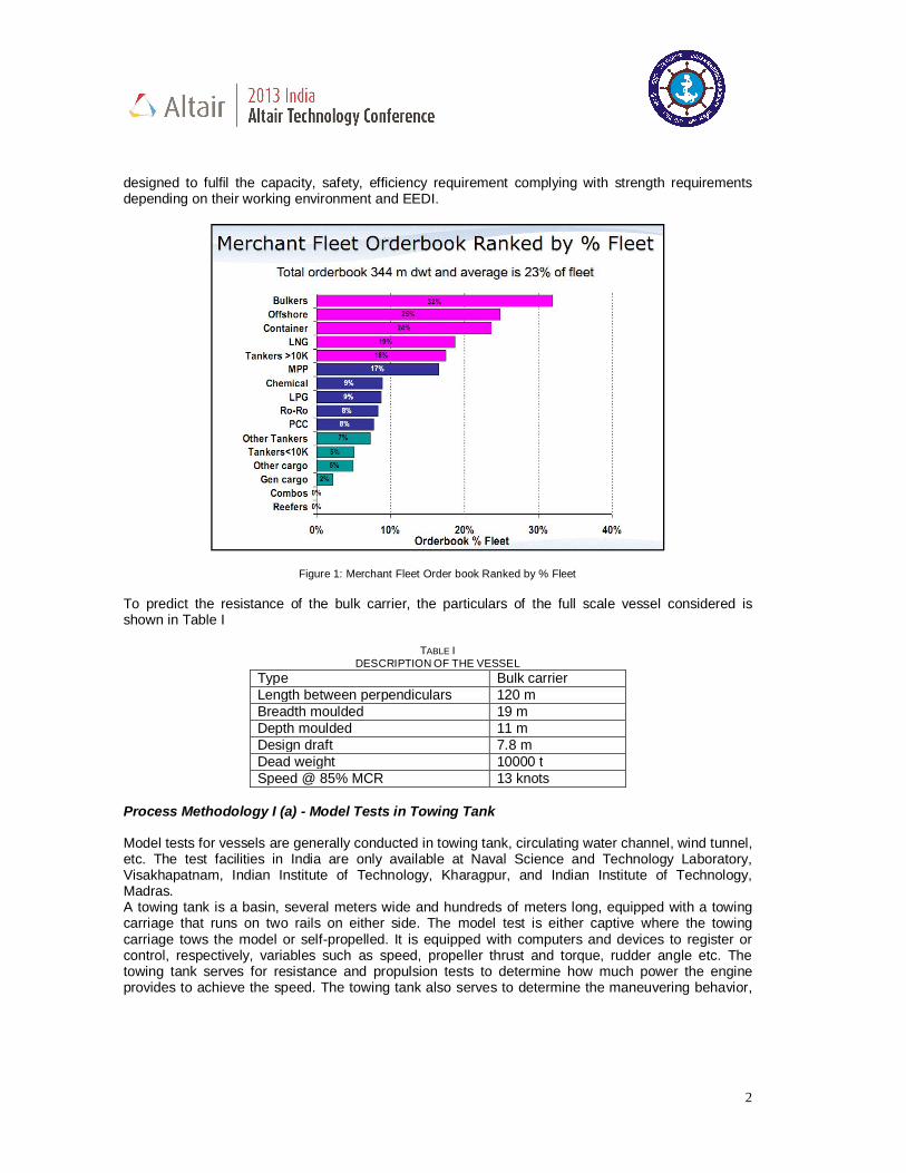
The hydrodynamic performance of a vessel depends on the shape of the hull. Therefore it is important that the hull form be carefully designed to minimize pressure distribution and resistance. A CFD analysis for the full scale bulk carrier is made to estimate the resistance at different velocities. A 3D steady state, incompressible viscous flow analysis for 8, 12 and 14 knots at 7.8 m draft level is executed for zero offset flow angle using the CFD package ACUSOLVE and the results are compared with experimentally obtained model test results. An attempt is made to simulate free surface interaction between the bulk carrier and water using the Smooth Particle Hydrodynamics method available in RADIOSS solver. Introduction Ship design is a compromise of various aspects like speed, power, dead weight (cargo carrying capacity), stability, sea keeping, trade routes, etc. For a vessel moving at a particular speed in high seas, it is designed such that power generated by the propulsion unit, consisting of engine and propeller, overcomes the resistance experienced due to speed and dead weight. So to compromise on power, ship builders normally go by the proven designs i.e. constructing similar ships to avoid any risks instead of looking for design alternatives. Vast research is being done in hydrodynamics to reduce power by modifying the ship hull form and its optimization requires a lot of skill and knowledge about many aspects like the pressure distribution, components of resistance and sea state. Viscous resistance and wave making resistance mainly contribute to the resistance of the ship and is estimated by model test where in the hull form is scaled down to estimate the power required and the results are extrapolated to full scale vessel. EEDI essentially defines the minimum energy efficiency level expressed in tons of CO2 emitted per 'Capacity mile' which all new ships must comply. EEDI is a measure related to the deadweight, speed and engine power of the vessel. The engine is selected such that the emissions from the vessel are within the limits of EEDI. This is where CFD comes in handy to predict the resistance of the various hull forms quickly. A bulk carrier is a merchant ship specially designed to transport unpackaged bulk cargo, such as grains, coal, ore, and cement in its cargo holds. The increasing demand and economic forces has influenced their growth in size and sophistication as shown in Fig 1[1]. The present bulkers are
2
designed to fulfil the capacity, safety, efficiency requirement complying with strength requirements depending on their working environment and EEDI.
Figure 1: Merchant Fleet Order book Ranked by % Fleet To predict the resistance of the bulk carrier, the particulars of the full scale vessel considered is shown in Table I
TABLE I DESCRIPTION OF THE VESSEL
Type Bulk carrier Length between perpendiculars 120 m Breadth moulded 19 m Depth moulded 11 m Design draft 7.8 m Dead weight 10000 t Speed @ 85% MCR 13 knots
Process Methodology I (a) - Model Tests in Towing Tank Model tests for vessels are generally conducted in towing tank, circulating water channel, wind tunnel, etc. The test facilities in India are only available at Naval Science and Technology Laboratory, Visakhapatnam, Indian Institute of Technology, Kharagpur, and Indian Institute of Technology, Madras. A towing tank is a basin, several meters wide and hundreds of meters long, equipped with a towing carriage that runs on two rails on either side. The model test is either captive where the towing carriage tows the model or self-propelled. It is equipped with computers and devices to register or control, respectively, variables such as speed, propeller thrust and torque, rudder angle etc. The towing tank serves for resistance and propulsion tests to determine how much power the engine provides to achieve the speed. The towing tank also serves to determine the maneuvering behavior,
3
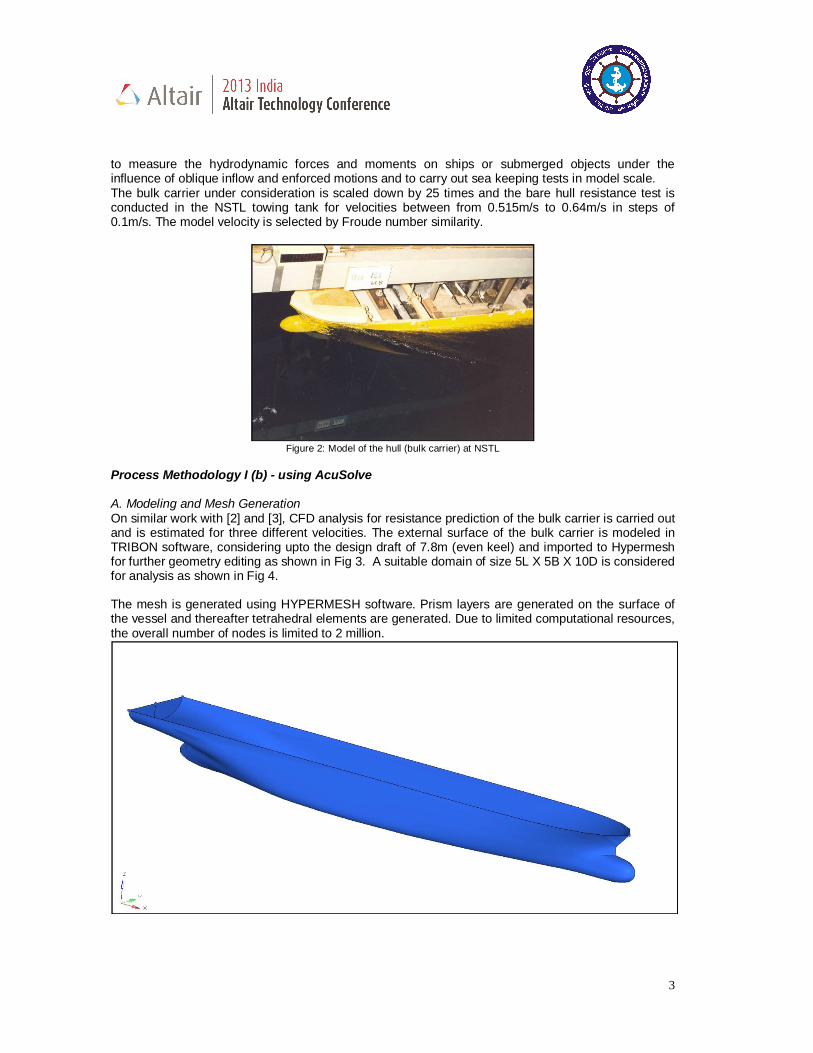
to measure the hydrodynamic forces and moments on ships or submerged objects under the influence of oblique inflow and enforced motions and to carry out sea keeping tests in model scale. The bulk carrier under consideration is scaled down by 25 times and the bare hull resistance test is conducted in the NSTL towing tank for velocities between from 0.515m/s to 0.64m/s in steps of 0.1m/s. The model velocity is selected by Froude number similarity.
Figure 2: Model of the hull (bulk carrier) at NSTL
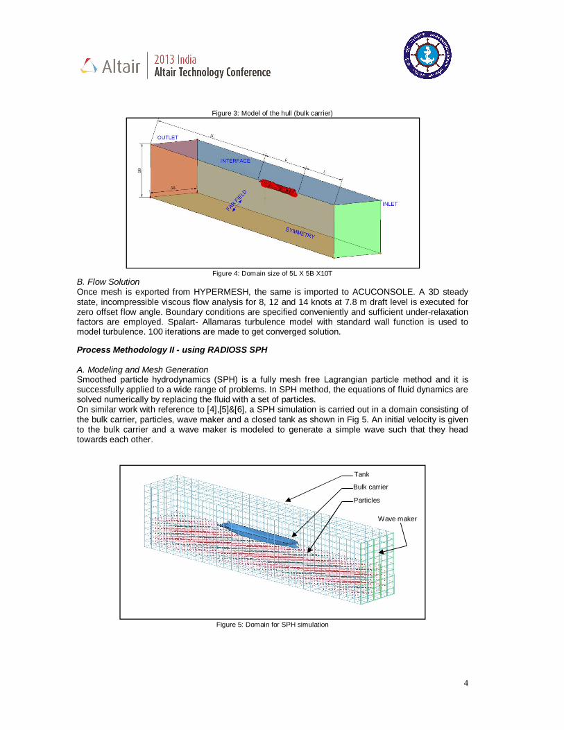
Process Methodology I (b) - using AcuSolve A. Modeling and Mesh Generation On similar work with [2] and [3], CFD analysis for resistance prediction of the bulk carrier is carried out and is estimated for three different velocities. The external surface of the bulk carrier is modeled in TRIBON software, considering upto the design draft of 7.8m (even keel) and imported to Hypermesh for further geometry editing as shown in Fig 3. A suitable domain of size 5L X 5B X 10D is considered for analysis as shown in Fig 4. The mesh is generated using HYPERMESH software. Prism layers are generated on the surface of the vessel and thereafter tetrahedral elements are generated. Due to limited computational resources, the overall number of nodes is limited to 2 million.
4
Figure 3: Model of the hull (bulk carrier)
Figure 4: Domain size of 5L X 5B X10T
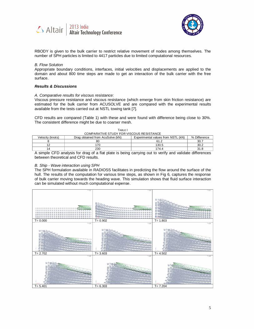
B. Flow Solution Once mesh is exported from HYPERMESH, the same is imported to ACUCONSOLE. A 3D steady state, incompressible viscous flow analysis for 8, 12 and 14 knots at 7.8 m draft level is executed for zero offset flow angle. Boundary conditions are specified conveniently and sufficient under-relaxation factors are employed. Spalart- Allamaras turbulence model with standard wall function is used to model turbulence. 100 iterations are made to get converged solution. Process Methodology II - using RADIOSS SPH A. Modeling and Mesh Generation Smoothed particle hydrodynamics (SPH) is a fully mesh free Lagrangian particle method and it is successfully applied to a wide range of problems. In SPH method, the equations of fluid dynamics are solved numerically by replacing the fluid with a set of particles. On similar work with reference to [4],[5]&[6], a SPH simulation is carried out in a domain consisting of the bulk carrier, particles, wave maker and a closed tank as shown in Fig 5. An initial velocity is given to the bulk carrier and a wave maker is modeled to generate a simple wave such that they head towards each other.
Figure 5: Domain for SPH simulation
Wave maker
Tank
Particles
Bulk carrier
5
RBODY is given to the bulk carrier to restrict relative movement of nodes among themselves. The number of SPH particles is limited to 4417 particles due to limited computational resources. B. Flow Solution Appropriate boundary conditions, interfaces, initial velocities and displacements are applied to the domain and about 800 time steps are made to get an interaction of the bulk carrier with the free surface. Results & Discussions A. Comparative results for viscous resistance: Viscous pressure resistance and viscous resistance (which emerge from skin friction resistance) are estimated for the bulk carrier from ACUSOLVE and are compared with the experimental results available from the tests carried out at NSTL towing tank [7]. CFD results are compared (Table 1) with these and were found with difference being close to 30%. The consistent difference might be due to coarser mesh.
TABLE I
COMPARATIVE STUDY FOR VISCOUS RESISTANCE Velocity (knots) Drag obtained from AcuSolve (kN) Experimental values from NSTL (kN) % Difference
8 80 61.2 30.7 12 170 130.5 30.2 14 230 174.4 31.8
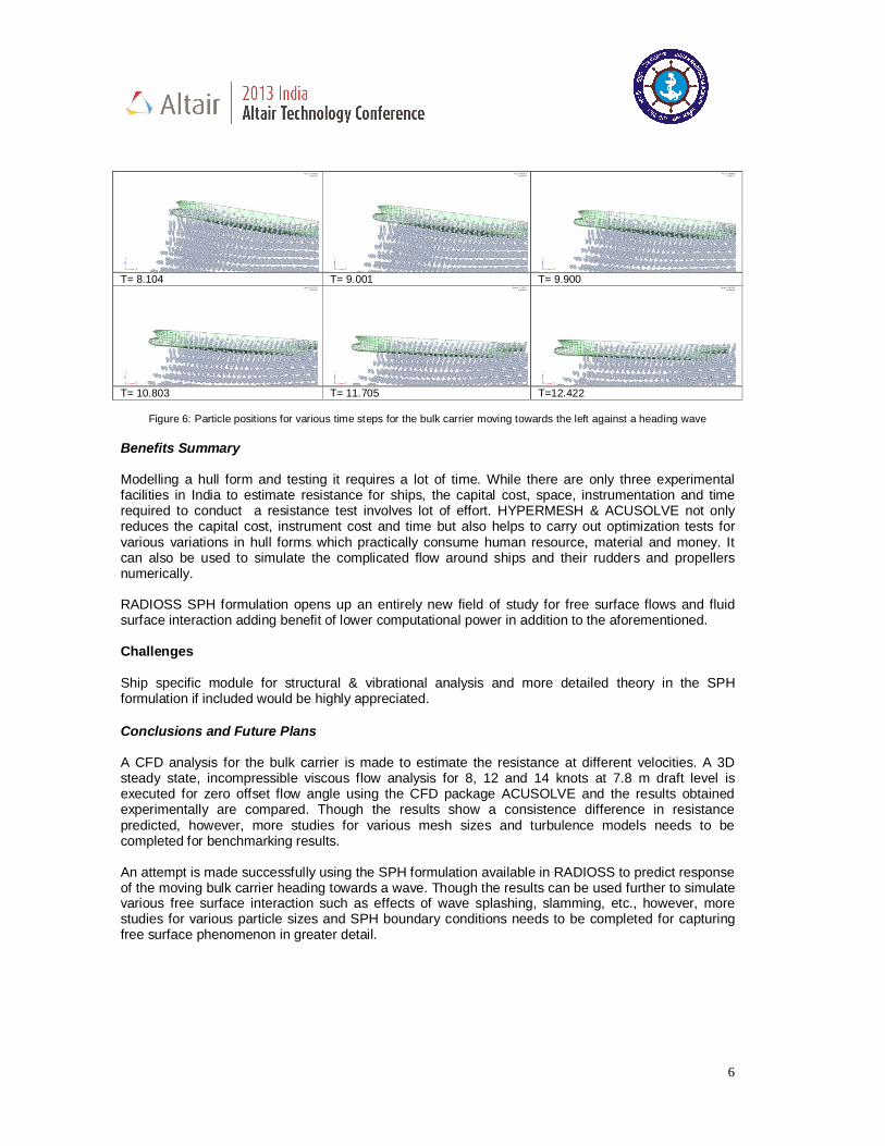
A simple CFD analysis for drag of a flat plate is being carrying out to verify and validate differences between theoretical and CFD results. B. Ship - Wave interaction using SPH The SPH formulation available in RADIOSS facilitates in predicting the flow around the surface of the hull. The results of the computation for various time steps, as shown in Fig 6, captures the response of bulk carrier moving towards the heading wave. This simulation shows that fluid surface interaction can be simulated without much computational expense.
T= 0.000 T= 0.902 T= 1.803
T= 2.702 T= 3.603 T= 4.502
T= 5.401 T= 6.303 T= 7.204
6
T= 8.104 T= 9.001 T= 9.900
T= 10.803 T= 11.705 T=12.422
Figure 6: Particle positions for various time steps for the bulk carrier moving towards the left against a heading wave
Benefits Summary Modelling a hull form and testing it requires a lot of time. While there are only three experimental facilities in India to estimate resistance for ships, the capital cost, space, instrumentation and time required to conduct a resistance test involves lot of effort. HYPERMESH & ACUSOLVE not only reduces the capital cost, instrument cost and time but also helps to carry out optimization tests for various variations in hull forms which practically consume human resource, material and money. It can also be used to simulate the complicated flow around ships and their rudders and propellers numerically. RADIOSS SPH formulation opens up an entirely new field of study for free surface flows and fluid surface interaction adding benefit of lower computational power in addition to the aforementioned. Challenges Ship specific module for structural & vibrational analysis and more detailed theory in the SPH formulation if included would be highly appreciated. Conclusions and Future Plans A CFD analysis for the bulk carrier is made to estimate the resistance at different velocities. A 3D steady state, incompressible viscous flow analysis for 8, 12 and 14 knots at 7.8 m draft level is executed for zero offset flow angle using the CFD package ACUSOLVE and the results obtained experimentally are compared. Though the results show a consistence difference in resistance predicted, however, more studies for various mesh sizes and turbulence models needs to be completed for benchmarking results. An attempt is made successfully using the SPH formulation available in RADIOSS to predict response of the moving bulk carrier heading towards a wave. Though the results can be used further to simulate various free surface interaction such as effects of wave splashing, slamming, etc., however, more studies for various particle sizes and SPH boundary conditions needs to be completed for capturing free surface phenomenon in greater detail.

7
ACKNOWLEDGEMENTS The authors would like to thank Mr Ramesha, Mr. Kamleshwar Rajender, Mr Guda Karthik of Altair for their valuable support and contributions during the initial phases of the project. We would also like to thank our Director, Prof (Dr) S C Misra for encouraging us to present this paper.
REFERENCES
[1] SMM Advance Press Conference 23rd May 2012, World Shipping, CLARKSON RESEARCH [2] PRADEEP, J.S. B. Et al, ‘Comparative study for a ship hull with sonar dome at different
positions’, RINA International Conference on Ships and Offshore Technology – India, 2011. [3] Ram Mohan Pamoti, Chetan Raval, 'External Aerodynamics of a Truck with Roof Fairing for
Drag Reduction', Altair Hyperworks Technology Conference - India, 2012 [4] Daniel J. Veen and Tim P. Gourlay, SPH Study of High Speed Ship Slamming, Centre for
Marine Science and Technology,Curtin University of Technology,Perth, Western Australia [5] Yang Xiufeng, Peng Shiliu, Liu Moubin,Shao Jiaru, Numerical Simulation of Ballast Water by
SPH Method [6] Example-22 Ditching using ALE and SPH, Altair Hyperworks Tutorials [7] NSTL Report No NSTL/HR/HSTT/221/1,June 2010.