Embed Size (px)
Citation preview
Al-KhwarizmiEngineering!!!
JournalAl-Khwarizmi Engineering Journal, Vol. 7, No. 2, PP 22 - 35 (2011)
Comparative Study of the Mechanical Properties of (FS) and MIG Welded Joint in (AA7020-T6) Aluminum Alloy
Moneer Hammed Tolephih * Kadhim M. Mashloosh ** Zainab Waheed ***The Technical College/ Baghdad
* Email: [email protected]** Email: [email protected]
*** Email: [email protected]
(Received 24 October 2010; accepted 15 May 2011)
Abstract
A comprehensive practical study of typical mechanical properties of welded Aluminum alloy AA7020-T6 (Al-Mg-Zn), adopting friction stir welding (FSW) technique and conventional metal inert gas (MIG) technique, is well achieved in this work for real comparison purposes. The essences of present output findings were concentrated upon the FSW samples in respect to that MIG ones which can be summarized in the increase of the ultimate tensile strength for FSW was 340 MPa while it was 232 MPa for MIG welding, where it was for base metal 400 MPa. The minimum microhardness value for FSW was recorded at HAZ and it was 133 HV0.05 while it was 70 HV0.05 for MIG weld at the welding metal. The FSW produce 2470 N higher than MIG welding in the bending test and a decrease in the localized grain size for FSW in the stirred zone 12 µm and it was 37 µm for MIG while it was 32 µm for the base metal.
Keyword: FSW friction, stir welding, solid state, MIG metal inert gas, fusion, mechanical properties.
1. Introduction
Friction stir welding (FSW) is a solid state welding technique used for joining successfully aluminum alloys. This technique is being applied to the aerospace, automotive, and shipbuildingindustries, and it is attracting an increasing amount of research interest [1]. A friction stir butt weld is produced by plunging a rotating tool into the facing surfaces of two plates. The tool consists of a shoulder and a profiled pin emerging from it. As the rotating pin moves along the weld line, thematerial is heated up by the friction generated by the shoulder and stirred by the rotating pin in a process similar to an extrusion. Since the temperatures are well below the melting point, problems associated with the liquid/solid phasetransformation are avoided [2].
In 1940 experiments began in the USA, in attempt to weld magnesium with aluminum base metals, with the shielding of the arc by inert gases. Some years later the MIG (Metal Inert Gas)
welding process was also developed using a continuously fed metal wire as the electrode [3].Gas metal arc welding is a process that melts and joins metals by heating them with an arc established between a continuously fed filler wire electrode and the metals. Shielding of the arc and the molten weld pool is often obtained using inert gases such as argon and helium. This is the most widely used arc welding process for aluminum alloy [4]. FSW has several advantages over the commonly used fusion welding techniques:
1- The welding procedure is relatively simple with no consumables or filler metal.
2- Joint edge preparation is not needed.3- Oxide removal prior to welding is unnecessary.4- The procedure can be automated and carried
out in all positions [5].
Number of researchers was comparative between FSW and MIG welding for many aluminum alloys. For example, Mustafa Kemal Kulekci and et. al. [6] was study the mechanical
This page was created using Nitro PDF trial software.
To purchase, go to http://www.nitropdf.com/
Moneer Hammed Tolephih Al-Khwarizmi Engineering Journal, Vol. 7, No. 2, PP 22 - 35 (2011)
23
properties of welded joints of EN AW-6061-T6 aluminum alloy obtained with FSW and MIG welding. C. Hamelton and et. al. [7] was compare the mechanical performance of 6061-T6 corner welds produced through the FSW and MIG welding and correlated the tensile properties and fracture characteristics with the weld microstructure. Zhou Carzhi and et. al. [5] was study the fatigue properties of 5083 Al-Mg alloy welded by single pass FSW and double pass MIG welding, and compared between them. While GR Bradley and MN James were studied the geometry and microstructure of MIG and FS welded aluminum alloy 5383-H321 [8]. R. S. Mishra et al. had found that the Heat Affected Zone HAZ has the lowest strength due to significant coarsened precipitates and the development of free precipitates zones (FPZs) [9]. S. R. Ren et al. found that for FSW both tool rotation rate and travel speed exert a significant effect on the thermal input and mechanical properties, where the input heat increased with increasing of tool rotation rate in 6061Al-T6, 1050Al and 6063Al-T5, and they found that the fracture of FSW of heat treatable aluminum alloys usually occurs in the HAZ, i.e. the softest zone in the FSW joints due to significant coarsening of the precipitates while the variation in the rotation rate did not change the fracture mode [10], and that match to G. Raghu Babu [11]. M. A. Sutton et al. explain that as one travel from the crown to the root of the FSW, the grain size deceases, most likely due to the higher heat input near the crown that causes additional grain growth in this region [12]. While the porosity and kissing bond type defect in the stirred zone will affect the quality of the joint. [13].
Terry Khaled observed that FSW temperatures arrival to the Nugget Zone NZ and parts of theThermo Mechanically Affected Zone TMAZ, will cause at least partial dissolution of the hardening phases. Ordinarily, therefore, some softening within the NZ should be expected in heat treatable alloys that were welded in T-tempers. Some grain coarsening and softening could also take place in the HAZ [14].
In this study, FSW and MIG processes are experimentally compared using the output results obtained from mechanical tests and metallurgical examination performed on the welded joints of AA7020-T6 aluminum alloy. The main objectives were assessed to distinguish between those operational parameters ( for FSW were rotational spindle speed and feed, while for MIG the parameters were the current, argon gas flow and welding speed) that influence the magnitudes of
some mechanical properties of the joined metals in comparing with the base metals properties.
2. Experimental Work
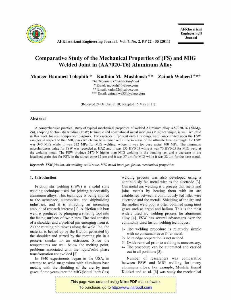
The material used in this work was AA7020-T6 (Al-Mg-Zn) aluminum alloy. A piece of this alloy was analyzed to find its chemical composition as shown in Table (1) by Spectrometer device in Al-Nasser Mechanical Industries Company and compared with the standard value. The welded plates were (200 mm)in length, (100 mm) in width, and (5 mm) in thickness as shown in figure (1). The actual mechanical properties are given in Table (2).
Table 1,Chemical Composition of AA7020-T6 Al-Alloy (wt %) [26].
Standard value Actual value
Si ≤0.35 0.24
Fe ≤0.40 0.27
Cu ≤0.20 0.10
Mn 0.05 – 0.5 0.08
Mg 1 – 1.5 1.23
Zn 4 – 5 4.16
Ti 0.08 0.03
Cr 0.10 – 0.35 0.15
Al BAL. BAL.
Fig.1. Shape and Size of the AA7020-T6 Aluminum Alloy Square Butt Joints Used for Welding Processes. (All Dimensions in mm).
This page was created using Nitro PDF trial software.
To purchase, go to http://www.nitropdf.com/
Moneer Hammed Tolephih Al-Khwarizmi Engineering Journal, Vol. 7, No. 2, PP 22 - 35 (2011)
24
Table 2,Actual Mechanical Properties of AA7020-T6 Al-Alloy.
Yield strength MPa
(Proof stress 0.2%)
Ultimate tensile strength MPa
Elongation EL.%
356.3 400 10.5
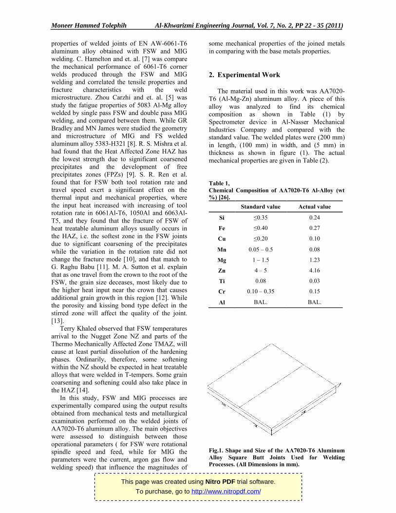
FSW joints were carried out using a High Speed Steel tool with 15mm shoulder diameter and the insert pin diameter and height were 5 mm and 4.85 mm, respectively, with cone angle 2.5° as shown in Figure (2). FSW was carried out at a different tool rotation of 450, 560, 710 and 900 rpm and a different transverse speed of 16, 25 and 40 mm/min by vertical milling machine (HMT milling machine) as shown in figure (3). The tool was rotated counter-clockwise to force softened material towards the root of the weld and to obtain a full joint at the root of the weld. The butted plates were clamped on a carbon steel backing plate as shown in figure (3). The rotating tool was fixed to the spindle of the milling machine and tilted 2.5º away from the spindle’s travel path.
In the FSW procedure, firstly, the surface of the work-piece brought into contact with the shoulder and insertion of the rotating FSW tool was stopped. At this stage, to generate the required pre-frictional heating. Then the rotating tool was moved along the joint line. The rollingdirection of the plates was the same as of the direction of the weld run. Single-sided welds were applied to the plates. Typically, the surface appearance of FSW was a regular series of partially circular ripples, which point towards the start of the weld. These ripples were essentially cycloid and were produced by the final sweep of the trailing circumferential edge of the shoulder during traverse. The surface color of FSW was silvery-white for studied material.
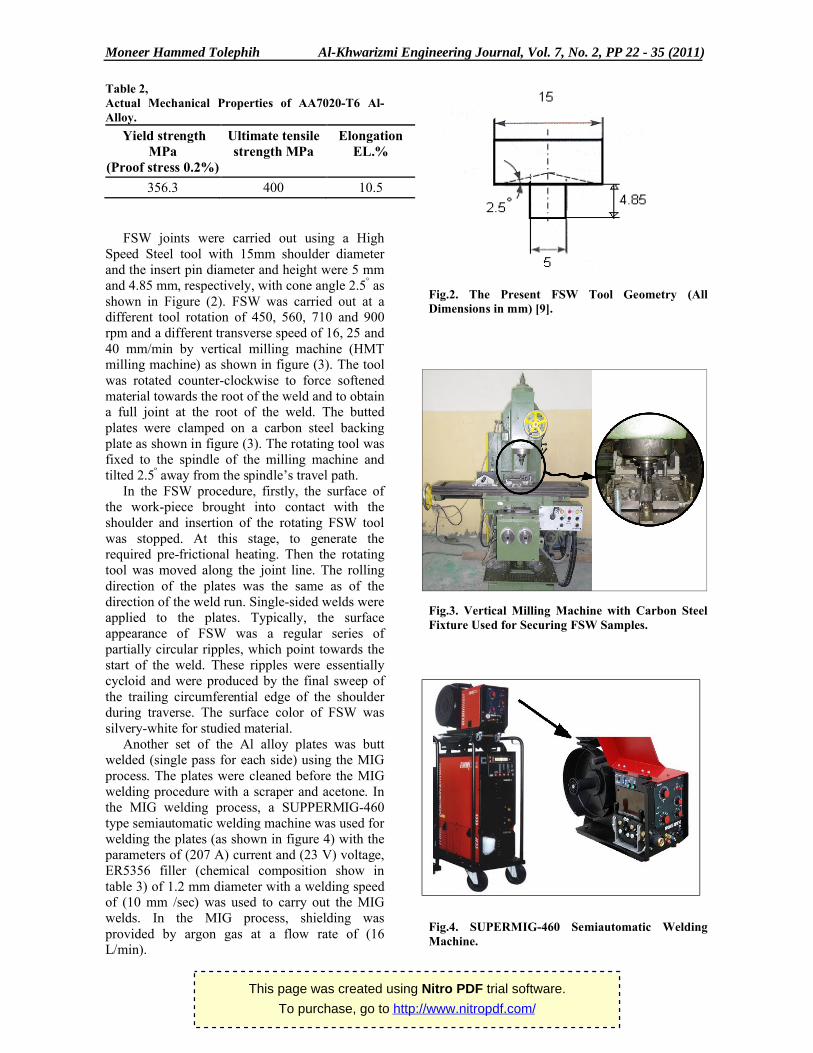
Another set of the Al alloy plates was buttwelded (single pass for each side) using the MIG process. The plates were cleaned before the MIG welding procedure with a scraper and acetone. In the MIG welding process, a SUPPERMIG-460 type semiautomatic welding machine was used for welding the plates (as shown in figure 4) with the parameters of (207 A) current and (23 V) voltage, ER5356 filler (chemical composition show in table 3) of 1.2 mm diameter with a welding speed of (10 mm /sec) was used to carry out the MIG welds. In the MIG process, shielding was provided by argon gas at a flow rate of (16 L/min).
Fig.2. The Present FSW Tool Geometry (All Dimensions in mm) [9].
Fig.3. Vertical Milling Machine with Carbon Steel Fixture Used for Securing FSW Samples.
Fig.4. SUPERMIG-460 Semiautomatic Welding Machine.
This page was created using Nitro PDF trial software.
To purchase, go to http://www.nitropdf.com/
Moneer Hammed Tolephih Al-Khwarizmi Engineering Journal, Vol. 7, No. 2, PP 22 - 35 (2011)
25
Table 3,Standard Chemical Composition of ER5356 Welding Wire [27].
Mg 4.5 – 5.5 %
Mn 0.05 –0.20 %
Si 0.25 % Max
Br 0.0008 Max
Ti 0.06 –0.20 %
Cu 0.10 %
Cr 0.05 –0.20 %
Zn 0.10 %
Fe 0.4 %
Al BAL.
To evaluate and compare the mechanical properties of the joints obtained with FSW and MIG processes, tensile, three points bending and microhardness tests were performed on welded joints. The FSW and MIG processes were also compared for the main metallurgical features. The tensile test specimens were machined out according to (ASTM B557M) and tested with (Zwick/Roell 100kN) tensile machine at room temperature and constant loading speed(5mm/min). The specimens of the welded plates that joined with FSW and MIG processes were taken in traverse direction of weld line. Three points bending test specimens were machined
according (ASME QW-462) while the test carried on Fristschi GumbH bending machine.
Vickers microhardness tests were performed on welded joints according (ASTM E384) with (50 g) load to compare and assess the hardnessdistribution of the FSW and MIG welding by using Zwick/Roell microhardness machine. Both of the processes were also compared for the main microstructural features after the specimens prepared according (ASTM E3) standard procedure and using Nikon microscope.
3. Results and Discussion
AA 7020-T6 aluminum alloy is seems to be extremely weldable by friction stir welding, since defect free welds were fabricated from the alloy under most welding conditions. Four rotational speeds (450, 560, 710 and 900 rpm) was used with three travel speeds (16, 25, and 40 mm/min) to study the effect of welding parameters on the mechanical properties and microstructure feature.The results of transverse tensile test are summarized in table (4). In general, both yield strength and ultimate tensile strength were reduced in the welded area compared with that of the parent material, due to a combination of dissolution, coarsening and reprecipitate of strengthening precipitates during FSW [9], or localized deformation [10].
. .
Table 4,Tensile Test Results for AA7020-T6 Aluminum Alloy FSW.
Welding Eff. %UTSW/UTSB
El. %Average UTS (MPa)
Average σy (MPa)0.2 offset
TravelSpeed (mm/min)
RotationSpeed (rpm)
—10.5400356.3Parent materials
694.45277248.516450
755.2529924325
633.65252.5241.540
583.2523122016560
81532324525
744.6296.5257.540
805.8318244.516710
826329252.525
744.25295.5266.540
796316.525716900
857.334024725
55321820340
This page was created using Nitro PDF trial software.
To purchase, go to http://www.nitropdf.com/
Moneer Hammed Tolephih Al-Khwarizmi Engineering Journal, Vol. 7, No. 2, PP 22 - 35 (2011)
26
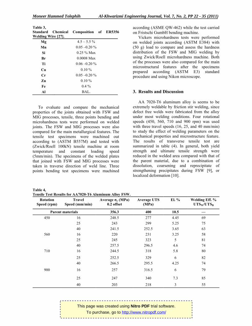
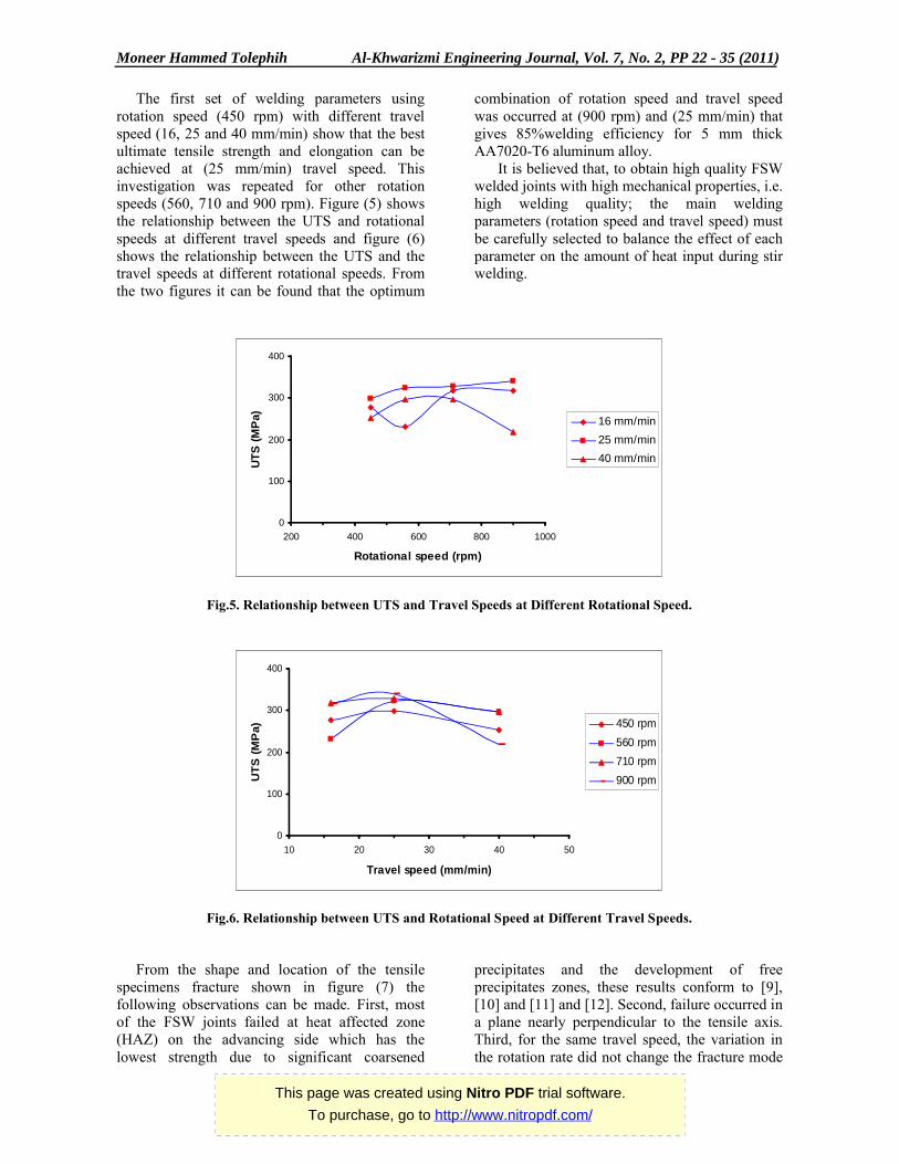
The first set of welding parameters using rotation speed (450 rpm) with different travel speed (16, 25 and 40 mm/min) show that the best ultimate tensile strength and elongation can be achieved at (25 mm/min) travel speed. This investigation was repeated for other rotation speeds (560, 710 and 900 rpm). Figure (5) shows the relationship between the UTS and rotational speeds at different travel speeds and figure (6) shows the relationship between the UTS and the travel speeds at different rotational speeds. From the two figures it can be found that the optimum
combination of rotation speed and travel speed was occurred at (900 rpm) and (25 mm/min) that gives 85%welding efficiency for 5 mm thick AA7020-T6 aluminum alloy.
It is believed that, to obtain high quality FSW welded joints with high mechanical properties, i.e. high welding quality; the main welding parameters (rotation speed and travel speed) must be carefully selected to balance the effect of each parameter on the amount of heat input during stir welding.
.
Fig.5. Relationship between UTS and Travel Speeds at Different Rotational Speed.
Fig.6. Relationship between UTS and Rotational Speed at Different Travel Speeds.
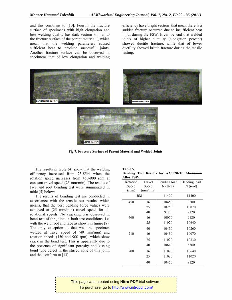
From the shape and location of the tensile specimens fracture shown in figure (7) the following observations can be made. First, most of the FSW joints failed at heat affected zone (HAZ) on the advancing side which has the lowest strength due to significant coarsened
precipitates and the development of free precipitates zones, these results conform to [9], [10] and [11] and [12]. Second, failure occurred in a plane nearly perpendicular to the tensile axis. Third, for the same travel speed, the variation in the rotation rate did not change the fracture mode
0
100
200
300
400
200 400 600 800 1000
Rotational speed (rpm)
UT
S (
MP
a) 16 mm/min
25 mm/min
40 mm/min
0
100
200
300
400
10 20 30 40 50
Travel speed (mm/min)
UT
S (
MP
a) 450 rpm
560 rpm
710 rpm
900 rpm
This page was created using Nitro PDF trial software.
To purchase, go to http://www.nitropdf.com/
Moneer Hammed Tolephih Al-Khwarizmi Engineering Journal, Vol. 7, No. 2, PP 22 - 35 (2011)
27
and this conforms to [10]. Fourth, the fracture surface of specimens with high elongation and best welding quality has dark section similar to the fracture surface of the parent material (, which mean that the welding parameters caused sufficient heat to produce successful joints. Another fracture surface can be observed in specimens that of low elongation and welding
efficiency have bright section that mean there is a sudden fracture occurred due to insufficient heat input during the FSW. It can be said that welded joints of higher ductility (elongation percent) showed ductile fracture, while that of lower ductility showed brittle fracture during the tensile testing.
Fig.7. Fracture Surface of Parent Material and Welded Joints.
The results in table (4) show that the welding efficiency increased from 75-85% when the rotation speed increases from 450-900 rpm at constant travel speed (25 mm/min). The results of face and root bending test were summarized in table (5) below:
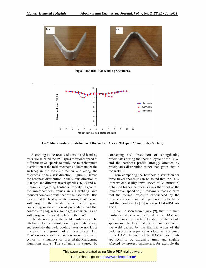
The results of bending test are conducted in accordance with the tensile test results, which means, that the best bending force values were achieved at (25 mm/min) travel speed for all rotational speeds. No cracking was observed in bend test of the joints in both test conditions, i.e. with the weld root and face as shown in figure (8). The only exception to that was the specimen welded at travel speed of (40 mm/min) and rotation speeds (450 and 900 rpm), which show crack in the bend test. This is apparently due to the presence of significant porosity and kissing bond type defect in the stirred zone of this joint, and that conform to [13].
Table 5,Bending Test Results for AA7020-T6 Aluminum Alloy FSW.
Bending loadN (root)
Bending loadN (face)
Travel Speed
(mm/min)
Rotation Speed(rpm)
11400 11400 BM
9500 10450 16450 10070 10260 25
9120 9120 40
9120 10070 16560 10640 11020 25
10260 10450 40
10070 10450 16710
10830 11020 25
8360 10640 40
10640 11020 16900 11020 11020 25
9120 10450 40
This page was created using Nitro PDF trial software.
To purchase, go to http://www.nitropdf.com/
Moneer Hammed Tolephih Al-Khwarizmi Engineering Journal, Vol. 7, No. 2, PP 22 - 35 (2011)
28
Fig.8. Face and Root Bending Specimens.
.
Fig.9. Microhardness Distribution of the Welded Area at 900 rpm (2.5mm Under Surface).
According to the results of tensile and bending tests, we selected the (900 rpm) rotational speed at different travel speeds to study the microhardness distribution at the mid thickness (2.5mm under the surface) in the x-axis direction and along the thickness in the y-axis direction. Figure (9) shows the hardness distribution in the x-axis direction at 900 rpm and different travel speeds (16, 25 and 40 mm/min). Regarding hardness property, in general the microhardness values in all welding area reduced compared with that of the base metal, this means that the heat generated during FSW caused softening of the welded area due to grain coarsening or dissolution of precipitates and that conform to [14], while some grain coarsening and softening could also take place in the HAZ
The decreasing in the weld hardness can be attributed to the dissolution of precipitates and subsequently the weld cooling rates do not favor nucleation and growth of all precipitates [15]. FSW creates a softened region around the weld center in a number of precipitation-hardening aluminum alloys. The softening is caused by
coarsening and dissolution of strengthening precipitates during the thermal cycle of the FSW, and the hardness profile strongly affected by precipitates distribution rather than grain size in the weld [9].
From comparing the hardness distribution for three travel speeds it can be found that the FSW joint welded at high travel speed of (40 mm/min) exhibited higher hardness values than that at the lower travel speed of (16 mm/min), that indicates that the thermal exposure experienced by the former was less than that experienced by the latter and that conform to [10] when welded 6061 Al-T651.
It can be seen from figure (9), that minimum hardness values were recorded in the HAZ and this explains the fracture location of the tensile specimens. The local material softening occurs in the weld caused by the thermal action of the welding process in particular a localized softening in the HAZ. The width of the HAZ in most joints are seem to be extremely small and slightly affected by process parameters, for example the
0
20
40
60
80
100
120
140
160
-12 -10 -8 -6 -4 -2 0 2 4 6 8 10 12
Position from the weld center line (mm)
Mic
roh
ard
ness H
V0.0
5
16 mm/min
25 mm/min
40 mm/min
This page was created using Nitro PDF trial software.
To purchase, go to http://www.nitropdf.com/
Moneer Hammed Tolephih Al-Khwarizmi Engineering Journal, Vol. 7, No. 2, PP 22 - 35 (2011)
29
hardness distribution of the joint welded at (25 mm/min ) did not show any HAZ and the average hardness across the joint is comparable to that of the base alloy and that conform to [16, 17].
It seems that at 900 rpm (the highest rotational speed used), which will produce the maximum heat input and that leads to maximum ductility result from this heat. At the same time, this speed will cause higher rate of plastic deformation which might cause the practical increase in hardness value. These heat input and plastic deformation caused refining in grain size as compared with the base metal. It is obvious that for the same metal, the finer grains, the higher strength and hardness. This might explain the unexpected results (increase in both hardness and ductility) at the higher rotation speed.
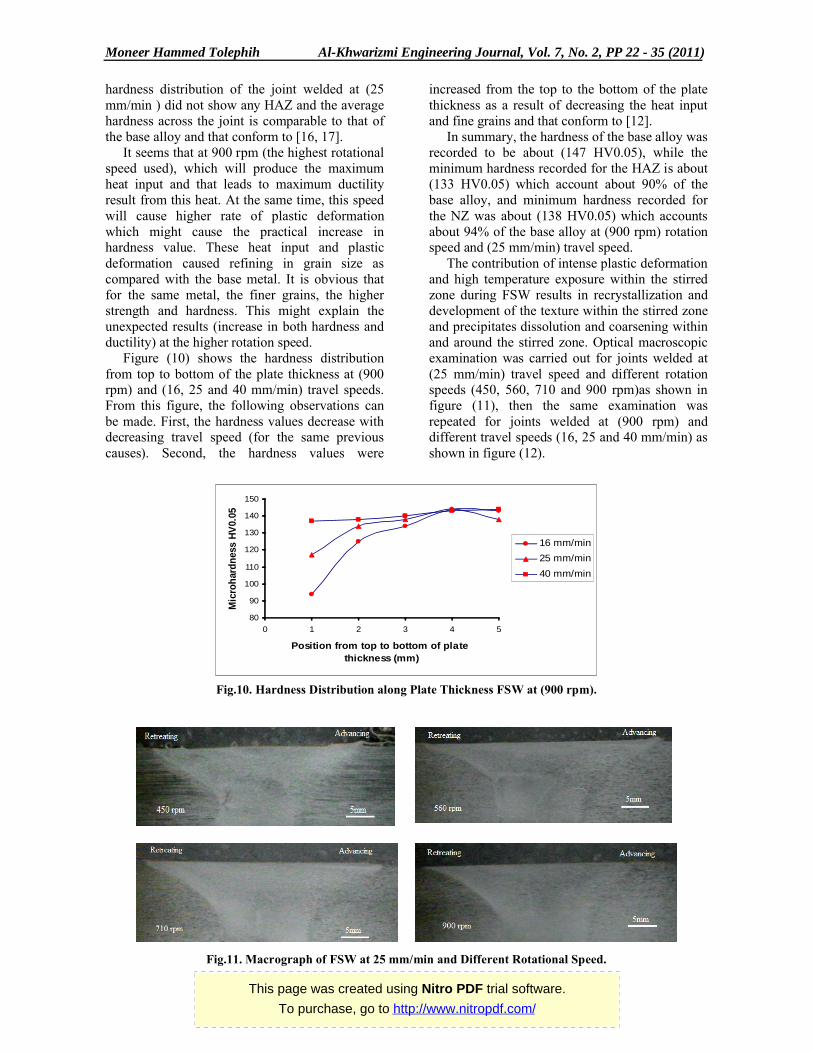
Figure (10) shows the hardness distribution from top to bottom of the plate thickness at (900 rpm) and (16, 25 and 40 mm/min) travel speeds. From this figure, the following observations can be made. First, the hardness values decrease with decreasing travel speed (for the same previous causes). Second, the hardness values were
increased from the top to the bottom of the plate thickness as a result of decreasing the heat input and fine grains and that conform to [12].
In summary, the hardness of the base alloy was recorded to be about (147 HV0.05), while the minimum hardness recorded for the HAZ is about (133 HV0.05) which account about 90% of the base alloy, and minimum hardness recorded for the NZ was about (138 HV0.05) which accounts about 94% of the base alloy at (900 rpm) rotation speed and (25 mm/min) travel speed.
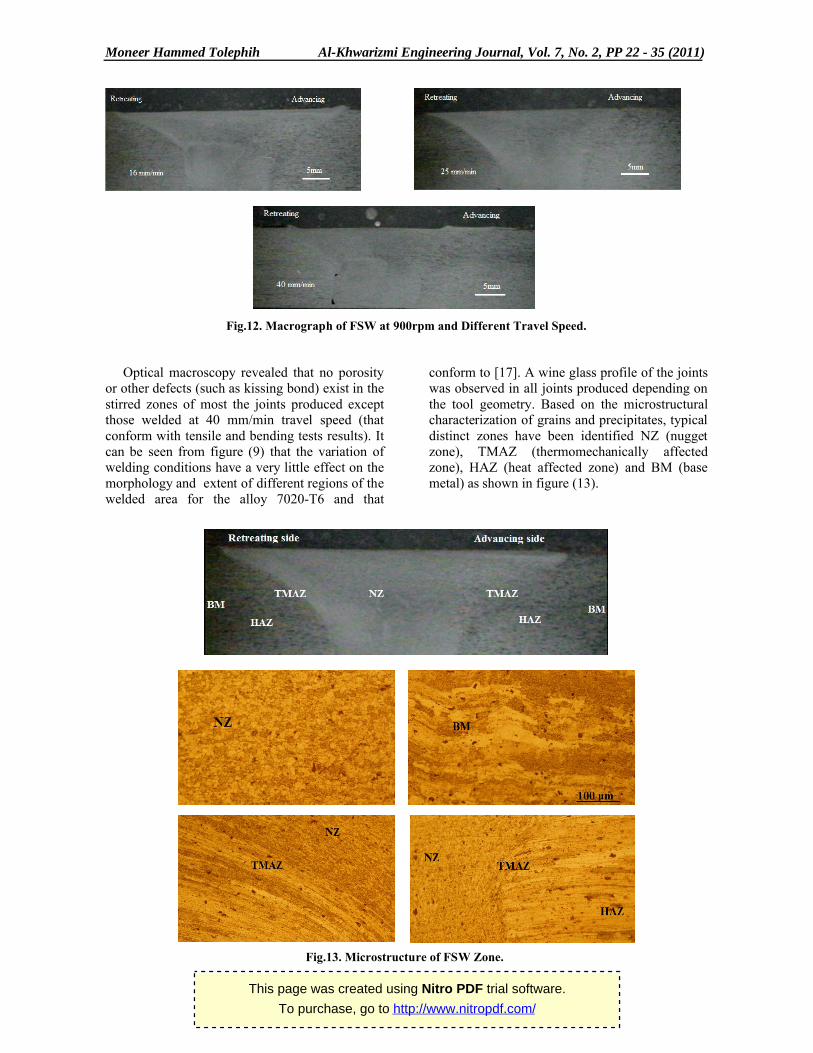
The contribution of intense plastic deformation and high temperature exposure within the stirred zone during FSW results in recrystallization and development of the texture within the stirred zone and precipitates dissolution and coarsening within and around the stirred zone. Optical macroscopic examination was carried out for joints welded at (25 mm/min) travel speed and different rotation speeds (450, 560, 710 and 900 rpm)as shown in figure (11), then the same examination was repeated for joints welded at (900 rpm) and different travel speeds (16, 25 and 40 mm/min) as shown in figure (12).
.
Fig.10. Hardness Distribution along Plate Thickness FSW at (900 rpm).
.
Fig.11. Macrograph of FSW at 25 mm/min and Different Rotational Speed.
80
90
100
110
120
130
140
150
0 1 2 3 4 5
Position from top to bottom of plate thickness (mm)
Mic
roh
ard
nes
s H
V0.
05
16 mm/min
25 mm/min
40 mm/min
This page was created using Nitro PDF trial software.
To purchase, go to http://www.nitropdf.com/
Moneer Hammed Tolephih Al-Khwarizmi Engineering Journal, Vol. 7, No. 2, PP 22 - 35 (2011)
30
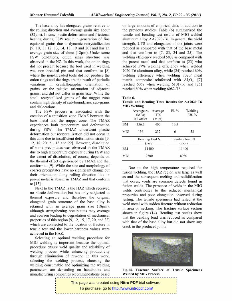
Fig.12. Macrograph of FSW at 900rpm and Different Travel Speed.
Optical macroscopy revealed that no porosity or other defects (such as kissing bond) exist in the stirred zones of most the joints produced except those welded at 40 mm/min travel speed (that conform with tensile and bending tests results). It can be seen from figure (9) that the variation of welding conditions have a very little effect on the morphology and extent of different regions of the welded area for the alloy 7020-T6 and that
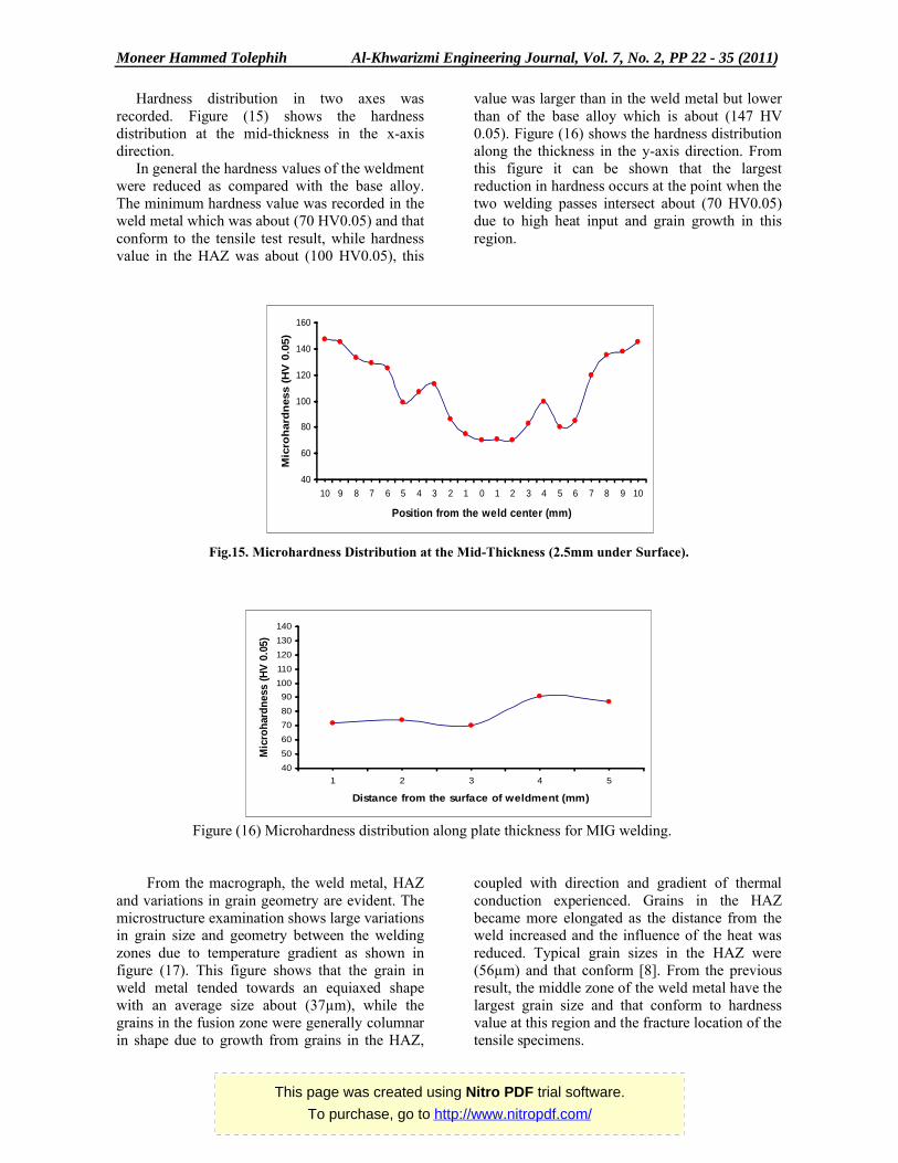
conform to [17]. A wine glass profile of the joints was observed in all joints produced depending on the tool geometry. Based on the microstructural characterization of grains and precipitates, typical distinct zones have been identified NZ (nugget zone), TMAZ (thermomechanically affected zone), HAZ (heat affected zone) and BM (base metal) as shown in figure (13).
. .
Fig.13. Microstructure of FSW Zone.
This page was created using Nitro PDF trial software.
To purchase, go to http://www.nitropdf.com/
Moneer Hammed Tolephih Al-Khwarizmi Engineering Journal, Vol. 7, No. 2, PP 22 - 35 (2011)
31
The base alloy has elongated grains relative to the rolling direction and average grain size about (32µm). Intense plastic deformation and frictional heating during FSW result in generation of fine equiaxed grains due to dynamic recrystallization [9, 10, 11 12, 13, 14, 18, 19 and 20] and has an average grain size of about (12µm). Under some FSW conditions, onion rings structure was observed in the NZ. In this work, the onion rings did not present because the tool used in welding was non-threaded pin and that conform to [8] where the non-threaded tools did not produce the onion rings and the rings are the result of periodic variations in crystallographic orientation of grains, or the relative orientation of adjacent grains, and did not differ in grain size. While the small recrystallized grains of the nugget zone contain high density of sub-boundaries, sub-grains and dislocations.
The FSW process is associated with the creation of a transition zone TMAZ between the base metal and the nugget zone. The TMAZ experiences both temperature and deformation during FSW. The TMAZ underwent plastic deformation but recrystallization did not occur in this zone due to insufficient deformation strain [9, 12, 18, 20, 21, 15 and 22]. However, dissolution of some precipitates was observed in the TMAZ due to high temperature exposure during FSW and the extent of dissolution, of course, depends on the thermal effect experienced by TMAZ and that conform to [9]. While the size and morphology of coarser precipitates have no significant change but their orientation along rolling direction like inparent metal is absent in TMAZ and that conform to [15].
Next to the TMAZ is the HAZ which received no plastic deformation but has only subjected to thermal exposure and therefore the original elongated grain structure of the base alloy is retained with an average grain size (18μm), although strengthening precipitates may overage and coarsen leading to degradation of mechanical properties of this region [9, 12, 15, 17, 20, and 22] which are connected to the location of fracture in tensile test and the lower hardness values were achieved in the HAZ.
Selecting an optimal welding procedure for MIG welding is important because the optimal procedure ensure weld quality and reliability of welding process while enhancing productivity through elimination of rework. In this work, selecting the welding process, choosing the welding consumable and optimizing the weldingparameters are depending on handbooks and manufacturing companies recommendations based
on large amounts of empirical data, in addition to the previous studies. Table (6) summarized the tensile and bending test results of MIG welded aluminum alloy AA7020-T6. In general the yield strength, UTS and elongation of the joints were reduced as compared with that of the base metal and that conform to [7, 23, 24 and 25]. The welding efficiency reached 58% as compared with the parent metal and that conform to [23] who achieved 57% welding efficiency when welded 7020-T6 aluminum alloy, while [24] reached 60% welding efficiency when welding 7020/ meal matrix composite reinforced with Al2O3, [7] reached 60% when welding 6101-T6 and [25] reached 60% when welding 6082-T6. . Table 6,Tensile and Bending Tests Results for AA7020-T6 MIG Welding
WeldingEff. %
El. %Average UTS
(MPa)
Average σy
(MPa)0.2 offset
—10.5400356.3BM
586232156MIG
Bending load N(root)
Bending load N(face)
1140011400BM
89309500MIG
Due to the high temperature required for fusion welding, the HAZ region was large as well as and the subsequent melting and solidification that occur, voids are common defects found in fusion welds. The presence of voids in the MIG welds contributes to the reduced mechanical properties and poor elongation observed during testing. The tensile specimens had failed at the weld metal with sudden fracture without reduction in area or necking. The fracture surface section shown in figure (14). Bending test results show that the bending load was reduced as compared with that of the base alloy but did not show any crack in the produced joints
Fig.14. Fracture Surface of Tensile Specimens Welded by MIG Process.
This page was created using Nitro PDF trial software.
To purchase, go to http://www.nitropdf.com/
Moneer Hammed Tolephih Al-Khwarizmi Engineering Journal, Vol. 7, No. 2, PP 22 - 35 (2011)
32
Hardness distribution in two axes was recorded. Figure (15) shows the hardness distribution at the mid-thickness in the x-axis direction.
In general the hardness values of the weldment were reduced as compared with the base alloy. The minimum hardness value was recorded in the weld metal which was about (70 HV0.05) and that conform to the tensile test result, while hardness value in the HAZ was about (100 HV0.05), this
value was larger than in the weld metal but lower than of the base alloy which is about (147 HV 0.05). Figure (16) shows the hardness distribution along the thickness in the y-axis direction. From this figure it can be shown that the largest reduction in hardness occurs at the point when the two welding passes intersect about (70 HV0.05) due to high heat input and grain growth in this region.
.
Fig.15. Microhardness Distribution at the Mid-Thickness (2.5mm under Surface).
Figure (16) Microhardness distribution along plate thickness for MIG welding.
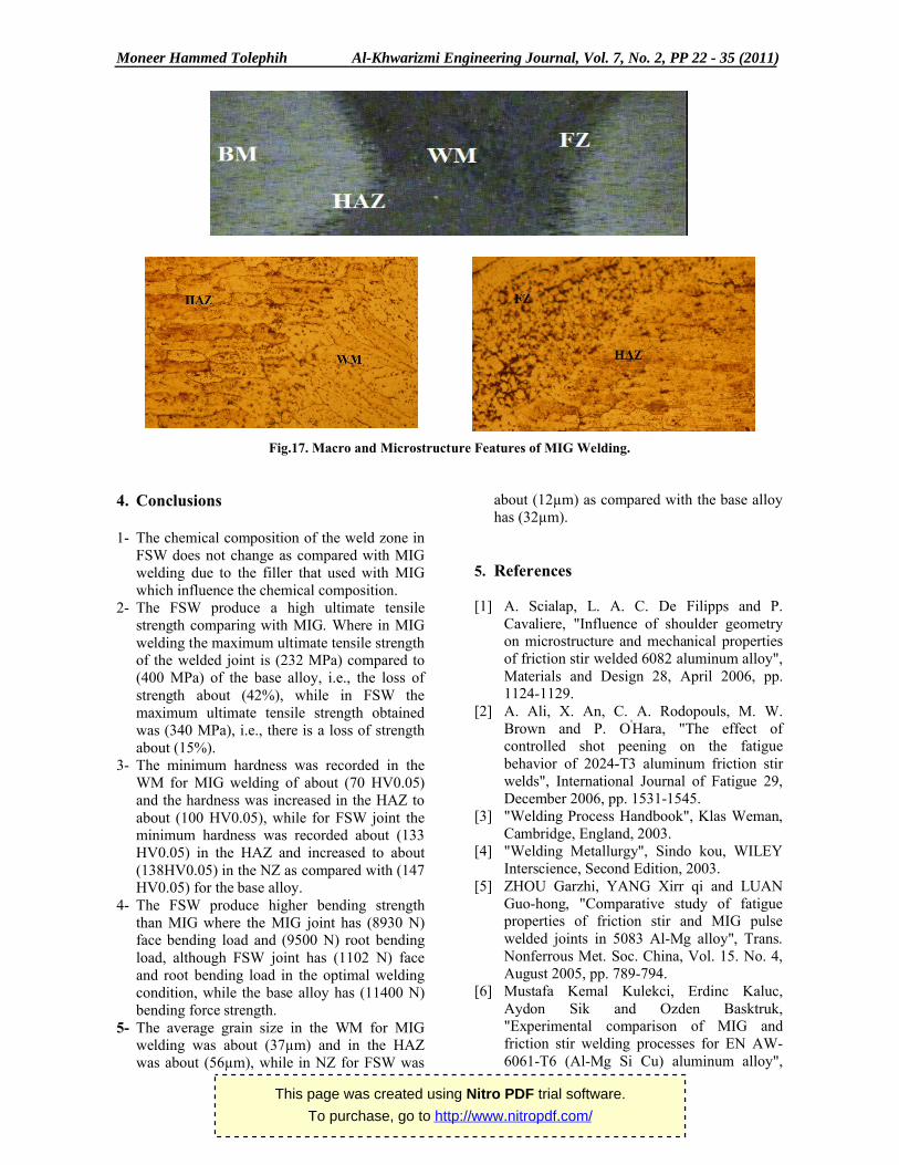
From the macrograph, the weld metal, HAZ and variations in grain geometry are evident. The microstructure examination shows large variations in grain size and geometry between the welding zones due to temperature gradient as shown in figure (17). This figure shows that the grain in weld metal tended towards an equiaxed shape with an average size about (37µm), while the grains in the fusion zone were generally columnar in shape due to growth from grains in the HAZ,
coupled with direction and gradient of thermal conduction experienced. Grains in the HAZ became more elongated as the distance from the weld increased and the influence of the heat was reduced. Typical grain sizes in the HAZ were (56µm) and that conform [8]. From the previous result, the middle zone of the weld metal have the largest grain size and that conform to hardness value at this region and the fracture location of the tensile specimens.
40
60
80
100
120
140
160
10 9 8 7 6 5 4 3 2 1 0 1 2 3 4 5 6 7 8 9 10
Position from the weld center (mm)
Mic
roh
ard
ness (
HV
0.0
5)
40
50
60
70
80
90
100
110
120
130
140
1 2 3 4 5
Distance from the surface of weldment (mm)
Mic
roh
ard
nes
s (H
V 0
.05)
This page was created using Nitro PDF trial software.
To purchase, go to http://www.nitropdf.com/
Moneer Hammed Tolephih Al-Khwarizmi Engineering Journal, Vol. 7, No. 2, PP 22 - 35 (2011)
33
Fig.17. Macro and Microstructure Features of MIG Welding.
4. Conclusions
1- The chemical composition of the weld zone in FSW does not change as compared with MIG welding due to the filler that used with MIG which influence the chemical composition.
2- The FSW produce a high ultimate tensile strength comparing with MIG. Where in MIG welding the maximum ultimate tensile strength of the welded joint is (232 MPa) compared to (400 MPa) of the base alloy, i.e., the loss of strength about (42%), while in FSW themaximum ultimate tensile strength obtained was (340 MPa), i.e., there is a loss of strength about (15%).
3- The minimum hardness was recorded in the WM for MIG welding of about (70 HV0.05) and the hardness was increased in the HAZ to about (100 HV0.05), while for FSW joint the minimum hardness was recorded about (133 HV0.05) in the HAZ and increased to about (138HV0.05) in the NZ as compared with (147 HV0.05) for the base alloy.
4- The FSW produce higher bending strength than MIG where the MIG joint has (8930 N)face bending load and (9500 N) root bending load, although FSW joint has (1102 N) face and root bending load in the optimal welding condition, while the base alloy has (11400 N) bending force strength.
5- The average grain size in the WM for MIG welding was about (37µm) and in the HAZ was about (56µm), while in NZ for FSW was
about (12µm) as compared with the base alloy has (32µm).
5. References
[1] A. Scialap, L. A. C. De Filipps and P. Cavaliere, "Influence of shoulder geometry on microstructure and mechanical properties of friction stir welded 6082 aluminum alloy", Materials and Design 28, April 2006, pp. 1124-1129.
[2] A. Ali, X. An, C. A. Rodopouls, M. W. Brown and P. O'Hara, "The effect of controlled shot peening on the fatiguebehavior of 2024-T3 aluminum friction stir welds", International Journal of Fatigue 29, December 2006, pp. 1531-1545.
[3] "Welding Process Handbook", Klas Weman, Cambridge, England, 2003.
[4] "Welding Metallurgy", Sindo kou, WILEY Interscience, Second Edition, 2003.
[5] ZHOU Garzhi, YANG Xirr qi and LUAN Guo-hong, "Comparative study of fatigue properties of friction stir and MIG pulse welded joints in 5083 Al-Mg alloy", Trans. Nonferrous Met. Soc. China, Vol. 15. No. 4, August 2005, pp. 789-794.
[6] Mustafa Kemal Kulekci, Erdinc Kaluc, Aydon Sik and Ozden Basktruk, "Experimental comparison of MIG and friction stir welding processes for EN AW-6061-T6 (Al-Mg Si Cu) aluminum alloy",
This page was created using Nitro PDF trial software.
To purchase, go to http://www.nitropdf.com/
Moneer Hammed Tolephih Al-Khwarizmi Engineering Journal, Vol. 7, No. 2, PP 22 - 35 (2011)
34
The Arabian Journal For Science and Engineering, Vol. 35, No. 1B, April 2010.
[7] C. Hamilton, S. Dymek and M. Blicharski, "Mechanical properties of Al 6101-T6 welds by Friction stir welding and metal inert gas welding", Archives of Metallurgy and Materials, Vol. 52, Issue I, 2007, pp. 67-72.
[8] GR Bradley and MN James, "Geometry and Microstructure of Metal Inert Gas and Friction Stir Welded Aluminum Alloy 5383-H321", University of Plymouth, October 2000, pp. 1-78.
[9] R. S. Mishra and Z. Y. Ma, "Friction Stir Welding and Processing", Material Science and Engineering R50, August 2005, pp. 1-78.
[10] S. R. Ren, Z.Y. Ma and L.Q. Chen, "Effect of welding parameters on tensile properties and fracture behavior of friction stir welded Al-Mg-Si alloy", Scripta Materialia 56, October 2006, pp. 69-72.
[11] G. Raghu Babu, K. G. K. Murti and G. Ranga Janardhana, "An experimental study on the effect of welding parameters on mechanical and microstructural properties of AA6082-T6 friction stir welded butt joints", ARPN Journal of Engineering and Applied Science, Vol. 3, No. 5, October 2008, pp. 68-74.
[12] M. A. Sutton, B. Yang, A. P. Reynolds and R. Taylor, "Microstructural studies of friction stir welds in 2024-T3 aluminum", Materials Science and Engineering A323, March 2001, pp. 160-166.
[13] G. Ç am, S. Güclüer, A. Ç akan and H. T. Serindag, "Mechanical properties of friction stir butt-welded Al5086-H32 plate", Journal of Achievements in Materials and Manufacturing Engineering", Vol.30, Issue:2, October 2008, pp. 151-154.
[14] Terry Khaled, "An Outsider Looks at Friction Stir Welding" Ph. D. thesis, July 2005.
[15] T. Venugopal, K. Srinivasa Roa and Prasad Roa, " Studies on friction stir welded AA7075-T6 aluminum alloy", Trans. Indian Inst. Met., Vol. 57, No. 6, December 2004, pp. 659-663.
[16] A. Barcellona, G. Buffa, L. Fratini and D. Palmeri, "On microstructural phenomena occurring in friction stir welding of aluminum alloys", Journal of Materials Processing Technology 177, 2006, pp. 340-343.
[17] Mohamedtahir M. Saeed Mulapeer Zibary, "Metallurgical and Mechanical Properties
of Some Friction Stir Welded Aluminum Alloys", PhD Thesis, University of Salahaddin-Erbil, 2009.
[18] M. Cabibbo, E. Meccia and E. Evangelista, "TEM analysis of friction stir-welded butt joint of Al-Si-Mg alloys", Materials Chemistry and Physics 81, 2003, pp. 289-292.
[19] G. M. Xie, Z. Y. Ma and L. Geng, "Development of a fine-grained microstructure and properties of a nugget zone in friction stir welded pure copper", Scripta Materialia 57, April 2007, pp. 73-76.
[20] N. T. Kumbhar and K. Bhanumurthy,"Friction Stir Welding of Al 6061Alloy", Asian J. Exp. Sci., Vol. 22, No. 2, 2008, pp. 63-74.
[21] R. Nandan, T. DebROY an H. K. Bhadeshia, "Recent Advances in Friction Stir Welding-Processing, Weldments Structure and properties", Progress in Materials Science 53, 2008, pp. 980-1023.
[22] P. Cavaliere, R. Nobile, F. W. Panella and A. Squillace, "Mechanical and microstructural behavior of 2024-7075 aluminum alloy sheets joined by friction stir welding", International Journal of Machine Tools and Manufacture 46, September 2005, pp. 588-594.
[23] Muafaq Mehdi Salih, "Studying the effect of joint design, angle and heat treatment on mechanical properties of the aluminum alloy weldments (7020-T6) by MIG process", Master Thesis, Technical College/Baghdad, November 2005.
[24] J. M. Gơmez de Salazer and M. I. Barrena, "Dissimilar fusion welding of AA7020/MMC reinforced with Al2O3
particles. Microstructure and mechanical properties", Materials Science and Engineering A352, November 2002, pp. 162-168.
[25] S. Missori and A. Sili, "Mechanical behavior of 6082-T6 aluminum alloy welds" Metallurgical Science and Technology, Vol. 18, 2000, pp.12-18.
[26] "Properties and Selection: Non-Ferrous Alloys and Special Purposes Materials", ASM Handbook, American Society for Metals, Vol. 2, 1992.
[27] "Specification for welding Rods, Electrodes and Filler Metal", ASME, Part C, July 1998.
.
This page was created using Nitro PDF trial software.
To purchase, go to http://www.nitropdf.com/
35 ، صفحة2، العدد 7مجلة الخوارزمي الھندسیة المجلد د طلیفح السعديمنیر حمی - 22 )2011(
35
دراسة مقارنة للخصائص المیكانیكیة للحام الخلط األحتكاكي والقوس المحمي
(AA7020-T6)بالغاز الخامل لسبیكة األلمنیوم
***زینب وحیدعبداهللا **كاظم مجبل مشلوش * منیر حمید طلیفح السعدي بغــداد/ الكلیـــة التقنیـــة
[email protected]: االلكترونيالبرید * [email protected]: البرید االلكتروني**
[email protected]: البرید االلكتروني***
الخالصة
وبطریقة اللحام (FSW)والتي تم لحامھا بطریقة الخلط االحتكاكي (AA7020-T6)لقد تم دراسة الخصائص المیكانیكیة لصفائح من سبیكة األلمنیوم
بینت نتائج البحث تفوق الخصائص المیكانیكیة للملحومات المنجزة بطریقة . وكانت النتائج العملیة ذات داللة في المقارنات . (MIG)بمساعدة الغاز الخامل
وللحام بمساعدة الغاز MPa 340حیث كانت قیمة الشد األقصى لملحومة الخلط االحتكاكي , از الخامل الخلط االحتكاكي على نظیراتھا الملحومة بطریقة الغ
وان ادنى قیمة صالدة مایكرویة للحام الخلط االحتكاكي سجلت في المنطقة المتأثرة MPa 400وان قیم الشد االقصى للمعدن االساس ھو MPa 232الخامل
وكذلك HV0.05 70حین سجلت ادنى قیمة صالدة مایكرویة للحام بمساعدة الغاز الخامل في المعدن الملحوم وكانت في HV0.05 133بالحرارة وكانت
عن قیمة حمل انحناء اللحام بمساعدة الغاز الخامل في حین انخفض حجم الحبیبات في N 2470سجل زیادة حمل االنحناء لملحومة الخلط االحتكاكي بحدود
.µm 32في اللحام بمساعدة الغاز الخامل في حین ان حجم الحبیبات للمعدن األساس كانت 37µmوكان 12µmى الخلط االحتكاكي ال
This page was created using Nitro PDF trial software.
To purchase, go to http://www.nitropdf.com/