Embed Size (px)
Citation preview
Proceedings of the 2nd
International Conference, The Federal Polytechnic, Ilaro, 10th
– 11th
Nov., 2020
899 Adeniran, J. Adeala & Joseph, O. Olaoye
COMPARATIVE STUDY ON STRUCTURAL MODELING, SIMULATION AND
ANALYTICAL DESIGN OF REINFORCED CONCRETE TRIPLE BOX CULVERT
USING STAADPRO AND SPREADSHEET
1Adeniran, J. Adeala &
1Joseph, O. Olaoye
1Department of Civil Engineering
Federal Polytechnic, Ilaro, Ogun state, Nigeria
08064999179
Abstract
Culvert is hydraulic structure that is used to convey and discharge water as part of drainage system. Many roads are
damaged by floods consequent upon unavailability or inefficient drainage system which claim many lives and
properties. In designing culvert, the analysis and design especially multiple cell-boxes is painstaking. Due to the
cumbersome analysis of culvert, several structural engineering softwares are developed and used for the analysis and
design of culverts such as spreadsheet. However, there is no RCC spread sheet written and developed that can be
used for analysis and design of multi box culvert which will make design simplier and faster on the field and in the
design office. The comparative analysis and design of multi box culvert using Staadpro and Spreadsheet is
undertaken in this research. The result produced by staadpro is not as reliable as that of spreadsheet in term of
analysis. In conclusion, it is reliable to develop program as an engineer such as spreadsheet, MATLAB, C++,
ABAQUS, ARDENAL e.t.c to solve engineering problem because most of the sofwares come with definite program
and assumption which are sometimes not clear to engineer.
Keywords: culvert, floods, analysis, design, staadpro, spreadsheet
Introduction
Culvert is defined as a tunnel or buried structure constructed under roadways or railways to provide cross drainage
or take electrical cables from one side to other. It is totally enclosed by soil or ground. The design of culvert is based
on hydrological properties which are intensity of rainfall (i), duration of rainfall (t), frequency of rainfall, catchment
area (A) and hydraulic properties of flow such as flow rate (Q), velocity of flow (V) and cross sectional area of
culvert which determine its size.
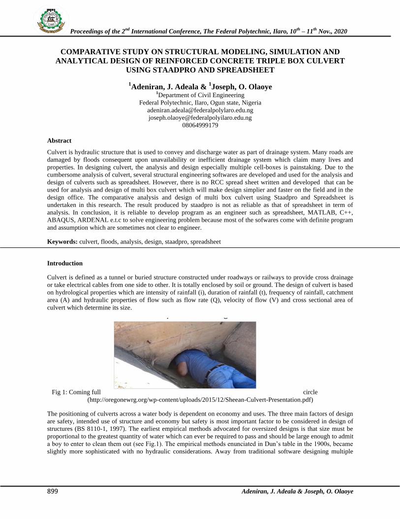
Fig 1: Coming full circle
(http://oregonewrg.org/wp-content/uploads/2015/12/Sheean-Culvert-Presentation.pdf)
The positioning of culverts across a water body is dependent on economy and uses. The three main factors of design
are safety, intended use of structure and economy but safety is most important factor to be considered in design of
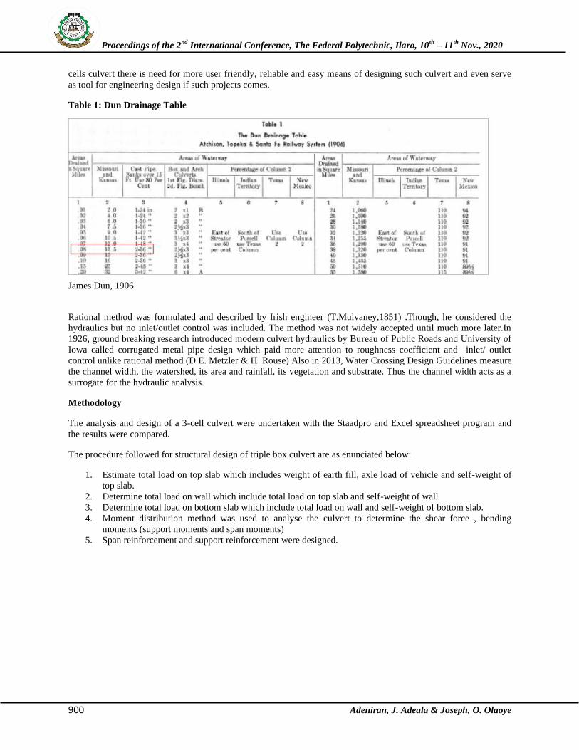
structures (BS 8110-1, 1997). The earliest empirical methods advocated for oversized designs is that size must be
proportional to the greatest quantity of water which can ever be required to pass and should be large enough to admit
a boy to enter to clean them out (see Fig.1). The empirical methods enunciated in Dun’s table in the 1900s, became
slightly more sophisticated with no hydraulic considerations. Away from traditional software designing multiple
Proceedings of the 2nd
International Conference, The Federal Polytechnic, Ilaro, 10th
– 11th
Nov., 2020
900 Adeniran, J. Adeala & Joseph, O. Olaoye
cells culvert there is need for more user friendly, reliable and easy means of designing such culvert and even serve
as tool for engineering design if such projects comes.
Table 1: Dun Drainage Table
James Dun, 1906
Rational method was formulated and described by Irish engineer (T.Mulvaney,1851) .Though, he considered the
hydraulics but no inlet/outlet control was included. The method was not widely accepted until much more later.In
1926, ground breaking research introduced modern culvert hydraulics by Bureau of Public Roads and University of
Iowa called corrugated metal pipe design which paid more attention to roughness coefficient and inlet/ outlet
control unlike rational method (D E. Metzler & H .Rouse) Also in 2013, Water Crossing Design Guidelines measure
the channel width, the watershed, its area and rainfall, its vegetation and substrate. Thus the channel width acts as a
surrogate for the hydraulic analysis.
Methodology
The analysis and design of a 3-cell culvert were undertaken with the Staadpro and Excel spreadsheet program and
the results were compared.
The procedure followed for structural design of triple box culvert are as enunciated below:
1. Estimate total load on top slab which includes weight of earth fill, axle load of vehicle and self-weight of
top slab.
2. Determine total load on wall which include total load on top slab and self-weight of wall
3. Determine total load on bottom slab which include total load on wall and self-weight of bottom slab.
4. Moment distribution method was used to analyse the culvert to determine the shear force , bending
moments (support moments and span moments)
5. Span reinforcement and support reinforcement were designed.
Proceedings of the 2nd
International Conference, The Federal Polytechnic, Ilaro, 10th
– 11th
Nov., 2020
901 Adeniran, J. Adeala & Joseph, O. Olaoye
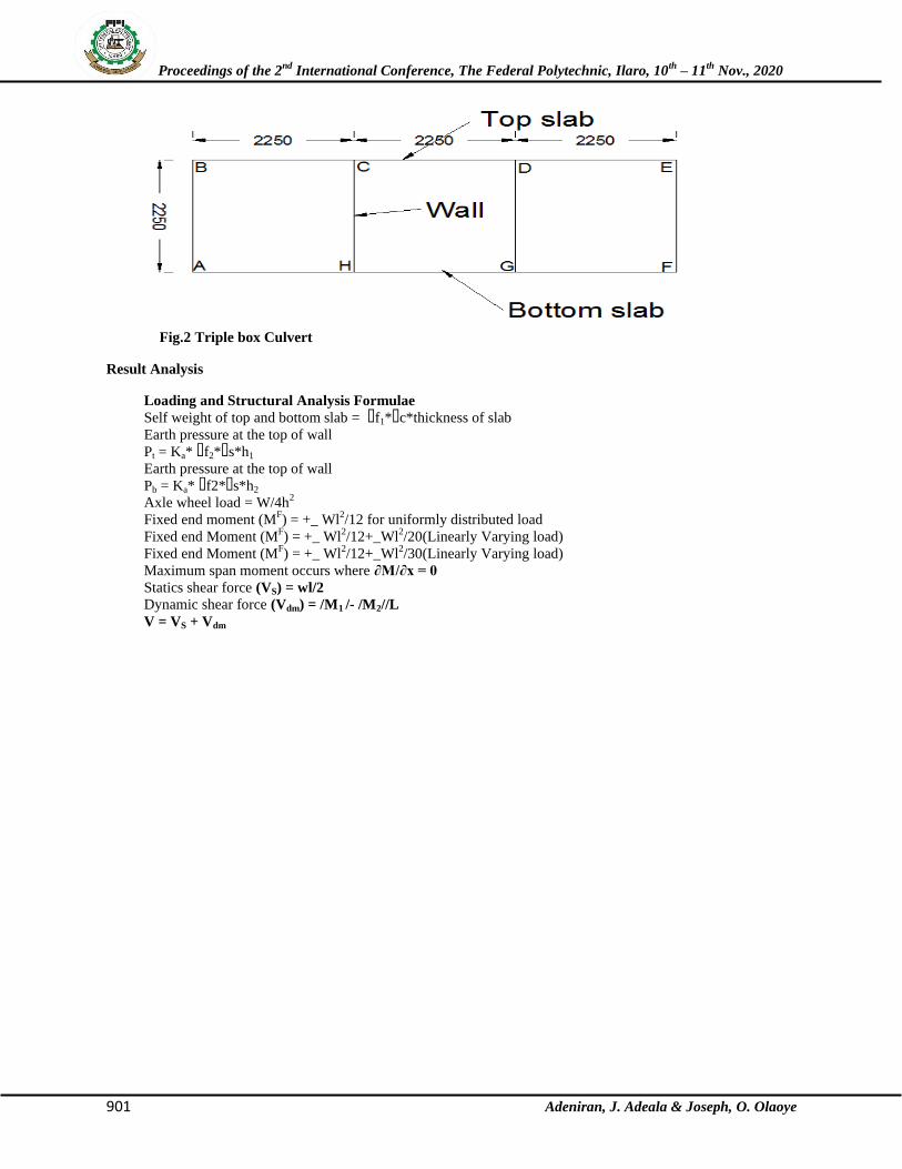
Fig.2 Triple box Culvert
Result Analysis
Loading and Structural Analysis Formulae
Self weight of top and bottom slab = ɤf1*ɤc*thickness of slab
Earth pressure at the top of wall
Pt = Ka* ɤf2*ɤs*h1
Earth pressure at the top of wall
Pb = Ka* ɤf2*ɤs*h2
Axle wheel load = W/4h2
Fixed end moment (MF) = +_ Wl
2/12 for uniformly distributed load
Fixed end Moment (MF) = +_ Wl
2/12+_Wl
2/20(Linearly Varying load)
Fixed end Moment (MF) = +_ Wl
2/12+_Wl
2/30(Linearly Varying load)
Maximum span moment occurs where ∂M/∂x = 0
Statics shear force (VS) = wl/2
Dynamic shear force (Vdm) = /M1 /- /M2//L
V = VS + Vdm
Proceedings of the 2nd
International Conference, The Federal Polytechnic, Ilaro, 10th
– 11th
Nov., 2020
902 Adeniran, J. Adeala & Joseph, O. Olaoye
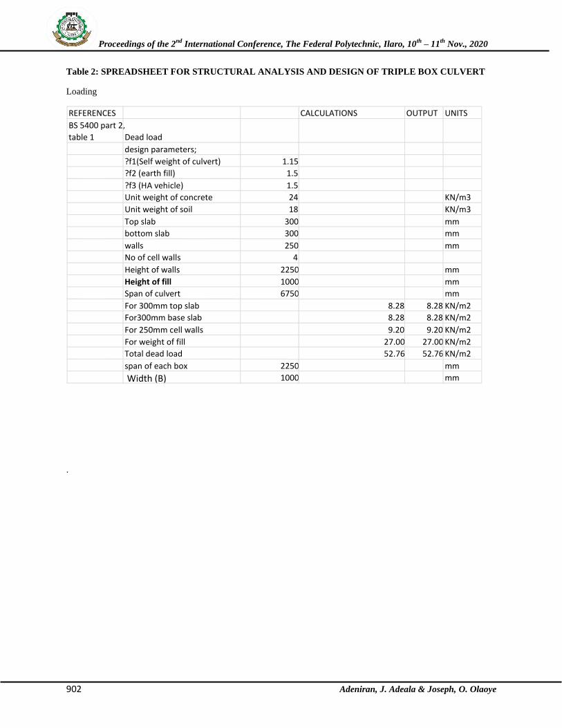
Table 2: SPREADSHEET FOR STRUCTURAL ANALYSIS AND DESIGN OF TRIPLE BOX CULVERT
Loading
.
REFERENCES CALCULATIONS OUTPUT UNITS BS 5400 part 2, table 1 Dead load
design parameters; ?f1(Self weight of culvert) 1.15 ?f2 (earth fill) 1.5 ?f3 (HA vehicle) 1.5 Unit weight of concrete 24 KN/m3 Unit weight of soil 18 KN/m3 Top slab 300 mm bottom slab 300 mm walls 250 mm No of cell walls 4 Height of walls 2250 mm Height of fill 1000 mm Span of culvert 6750 mm For 300mm top slab 8.28 8.28 KN/m2 For300mm base slab 8.28 8.28 KN/m2 For 250mm cell walls 9.20 9.20 KN/m2 For weight of fill 27.00 27.00 KN/m2 Total dead load 52.76 52.76 KN/m2 span of each box 2250 mm
Width (B) 1000 mm
Proceedings of the 2nd
International Conference, The Federal Polytechnic, Ilaro, 10th
– 11th
Nov., 2020
903 Adeniran, J. Adeala & Joseph, O. Olaoye
\\\
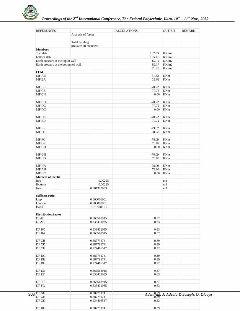
REFERENCES CALCULATIONS OUTPUT REMARK
Analysis of forces
Total bending
pressure on members
Members
Top slab 167.63 KN/m2
bottom slab 185.11 KN/m2
Earth pressure at the top of wall 62.12 KN/m2
Earth pressure at the bottom of wall 82.37 KN/m2
20.25 KN/m2
FEM
MF AB -31.33 KNm
MF BA 29.62 KNm
MF BC -70.72 KNm
MF CB 70.72 KNm
MF CH 0.00 KNm
MF CD -70.72 KNm
MF DC 70.72 KNm
MF DG 0.00 KNm
MF DE -70.72 KNm
MF ED 70.72 KNm
MF EF -29.62 KNm
MF FE 31.33 KNm
MF FG -78.09 KNm
MF GF 78.09 KNm
MF GD 0.00 KNm
MF GH -78.09 KNm
MF HG 78.09 KNm
MF HA -78.09 KNm
MF AH 78.09 KNm
MF HC 0.00 KNm
Moment of inertia
Itop 0.00225 m3
Ibottom 0.00225 m3
Iwall 0.001302083 m3
Stiffness ratio
ktop 0.000000001
kbottom 0.000000001
kwall 5.78704E-10
Distribution factor
DFAB 0.366568915 0.37
DFAH 0.633431085 0.63
DF BC 0.633431085 0.63
DF BA 0.366568915 0.37
DF CB 0.387791741 0.39
DF CD 0.387791741 0.39
DF CH 0.224416517 0.22
DF DC 0.387791741 0.39
DF DE 0.387791741 0.39
DF DG 0.224416517 0.22
DF ED 0.366568915 0.37
DF EF 0.633431085 0.63
DF FE 0.366568915 0.37
DF FG 0.633431085 0.63
DF GF 0.387791741 0.39
DF GH 0.387791741 0.39
DF GD 0.224416517 0.22
DF HG 0.387791741 0.39
DF HA 0.387791741 0.39
Proceedings of the 2nd
International Conference, The Federal Polytechnic, Ilaro, 10th
– 11th
Nov., 2020
904 Adeniran, J. Adeala & Joseph, O. Olaoye
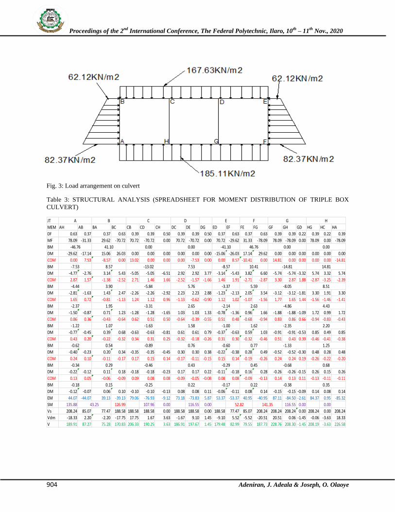
Fig. 3: Load arrangement on culvert
Table 3: STRUCTURAL ANALYSIS (SPREADSHEET FOR MOMENT DISTRIBUTION OF TRIPLE BOX
CULVERT)
JT
MEM AH AB BA BC CB CD CH DC DE DG ED EF FE FG GF GH GD HG HC HA
DF 0.63 0.37 0.37 0.63 0.39 0.39 0.50 0.39 0.39 0.50 0.37 0.63 0.37 0.63 0.39 0.39 0.22 0.39 0.22 0.39
MF 78.09 -31.33 29.62 -70.72 70.72 -70.72 0.00 70.72 -70.72 0.00 70.72 -29.62 31.33 -78.09 78.09 -78.09 0.00 78.09 0.00 -78.09
BM
DM -29.62 -17.14 15.06 26.03 0.00 0.00 0.00 0.00 0.00 0.00 -15.06 -26.03 17.14 29.62 0.00 0.00 0.00 0.00 0.00 0.00
COM 0.00 7.53 -8.57 0.00 13.02 0.00 0.00 0.00 -7.53 0.00 0.00 8.57 -10.41 0.00 14.81 0.00 0.00 0.00 0.00 -14.81
BM
DM -4.77 -2.76 3.14 5.43 -5.05 -5.05 -6.51 2.92 2.92 3.77 -3.14 -5.43 3.82 6.60 -5.74 -5.74 -3.32 5.74 3.32 5.74
COM 2.87 1.57 -1.38 -2.52 2.71 1.46 1.66 -2.52 -1.57 -1.66 1.46 1.91 -2.71 -2.87 3.30 2.87 1.88 -2.87 -3.25 -2.39
BM
DM -2.81 -1.63 1.43 2.47 -2.26 -2.26 -2.92 2.23 2.23 2.88 -1.23 -2.13 2.05 3.54 -3.12 -3.12 -1.81 3.30 1.91 3.30
COM 1.65 0.72 -0.81 -1.13 1.24 1.12 0.96 -1.13 -0.62 -0.90 1.12 1.02 -1.07 -1.56 1.77 1.65 1.44 -1.56 -1.46 -1.41
BM
DM -1.50 -0.87 0.71 1.23 -1.28 -1.28 -1.65 1.03 1.03 1.33 -0.78 -1.36 0.96 1.66 -1.88 -1.88 -1.09 1.72 0.99 1.72
COM 0.86 0.36 -0.43 -0.64 0.62 0.51 0.50 -0.64 -0.39 -0.55 0.51 0.48 -0.68 -0.94 0.83 0.86 0.66 -0.94 -0.83 -0.43
BM
DM -0.77 -0.45 0.39 0.68 -0.63 -0.63 -0.81 0.61 0.61 0.79 -0.37 -0.63 0.59 1.03 -0.91 -0.91 -0.53 0.85 0.49 0.85
COM 0.43 0.20 -0.22 -0.32 0.34 0.31 0.25 -0.32 -0.18 -0.26 0.31 0.30 -0.32 -0.46 0.51 0.43 0.39 -0.46 -0.41 -0.38
BM
DM -0.40 -0.23 0.20 0.34 -0.35 -0.35 -0.45 0.30 0.30 0.38 -0.22 -0.38 0.28 0.49 -0.52 -0.52 -0.30 0.48 0.28 0.48
COM 0.24 0.10 -0.11 -0.17 0.17 0.15 0.14 -0.17 -0.11 -0.15 0.15 0.14 -0.19 -0.26 0.24 0.24 0.19 -0.26 -0.22 -0.20
BM
DM -0.22 -0.12 0.11 0.18 -0.18 -0.18 -0.23 0.17 0.17 0.22 -0.11 -0.18 0.16 0.28 -0.26 -0.26 -0.15 0.26 0.15 0.26
COM 0.13 0.05 -0.06 -0.09 0.09 0.08 0.08 -0.09 -0.05 -0.08 0.08 0.08 -0.09 -0.13 0.14 0.13 0.11 -0.13 -0.11 -0.11
BM
DM -0.12 -0.07 0.06 0.10 -0.10 -0.10 -0.13 0.08 0.08 0.11 -0.06 -0.11 0.08 0.14 -0.15 -0.15 -0.09 0.14 0.08 0.14
EM 44.07 -44.07 39.13 -39.13 79.06 -76.93 -9.12 73.18 -73.83 5.87 53.37 -53.37 40.95 -40.95 87.11 -84.50 -2.61 84.37 0.95 -85.32
SM 135.88 126.99 107.96 0.00 116.55 0.00 116.55 0.00 0.00
Vs 208.24 85.07 77.47 188.58 188.58 188.58 0.00 188.58 188.58 0.00 188.58 77.47 85.07 208.24 208.24 208.24 0.00 208.24 0.00 208.24
Vdm -18.33 2.20 -2.20 -17.75 17.75 1.67 3.63 -1.67 9.10 1.45 -9.10 5.52 -5.52 -20.51 20.51 0.06 -1.45 -0.06 -3.63 18.33
V 189.91 87.27 75.28 170.83 206.33 190.25 3.63 186.91 197.67 1.45 179.48 82.99 79.55 187.73 228.76 208.30 -1.45 208.19 -3.63 226.58
-2.35 2.20-1.22 1.07 -1.63 1.58 -1.00 1.62
2.63 -4.86 4.43
-4.44 3.90 -5.84 5.76 -3.37 5.59
-2.37 1.95 -3.31 2.65 -2.14
10.41 -14.81 14.81
-8.05 8.51
-7.53 8.57 -13.02 7.53 -8.57
G H
-46.76 41.10 0.00 0.00 -41.10 46.76
A B C D E F
0.00 0.00
0.77 -1.33 1.25
-0.34 0.29 -0.29 0.45-0.46 0.43 -0.68
-0.62 0.54 -0.89 0.76 -0.60
0.68
0.22 -0.38 0.35
43.25 52.82
-0.18 0.15 -0.25 0.22 -0.17
141.35
Proceedings of the 2nd
International Conference, The Federal Polytechnic, Ilaro, 10th
– 11th
Nov., 2020
905 Adeniran, J. Adeala & Joseph, O. Olaoye
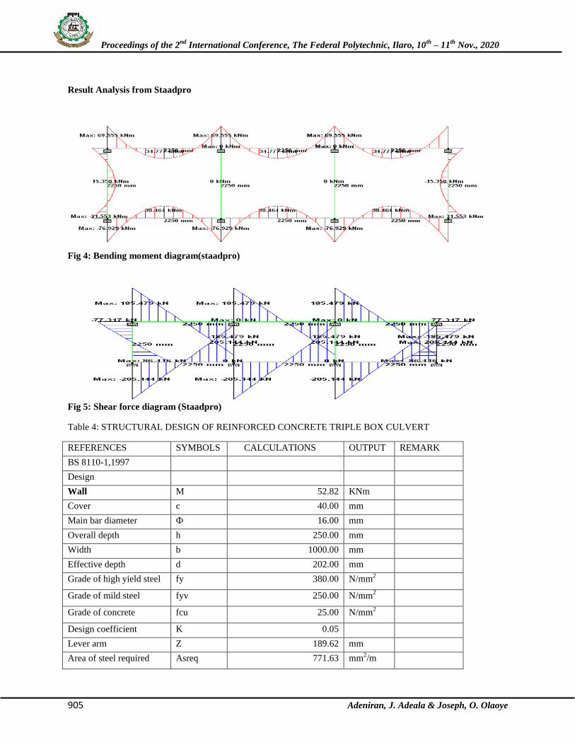
Result Analysis from Staadpro
Fig 4: Bending moment diagram(staadpro)
Fig 5: Shear force diagram (Staadpro)
Table 4: STRUCTURAL DESIGN OF REINFORCED CONCRETE TRIPLE BOX CULVERT
REFERENCES SYMBOLS CALCULATIONS OUTPUT REMARK
BS 8110-1,1997
Design
Wall M 52.82 KNm
Cover c 40.00 mm
Main bar diameter Ф 16.00 mm
Overall depth h 250.00 mm
Width b 1000.00 mm
Effective depth d 202.00 mm
Grade of high yield steel fy 380.00 N/mm2
Grade of mild steel fyv 250.00 N/mm2
Grade of concrete fcu 25.00 N/mm2
Design coefficient K 0.05
Lever arm Z 189.62 mm
Area of steel required Asreq 771.63 mm2/m
Proceedings of the 2nd
International Conference, The Federal Polytechnic, Ilaro, 10th
– 11th
Nov., 2020
906 Adeniran, J. Adeala & Joseph, O. Olaoye
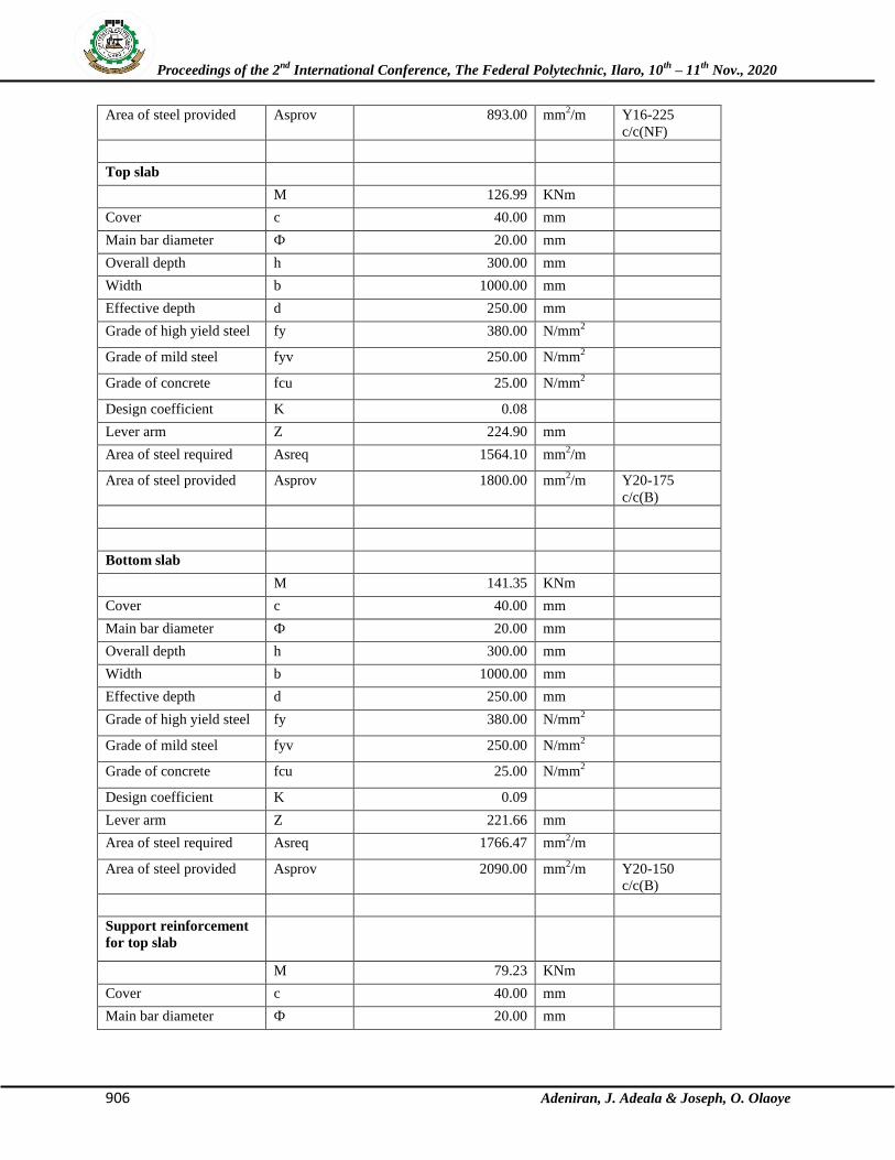
Area of steel provided Asprov 893.00 mm2/m Y16-225
c/c(NF)
Top slab
M 126.99 KNm
Cover c 40.00 mm
Main bar diameter Ф 20.00 mm
Overall depth h 300.00 mm
Width b 1000.00 mm
Effective depth d 250.00 mm
Grade of high yield steel fy 380.00 N/mm2
Grade of mild steel fyv 250.00 N/mm2
Grade of concrete fcu 25.00 N/mm2
Design coefficient K 0.08
Lever arm Z 224.90 mm
Area of steel required Asreq 1564.10 mm2/m
Area of steel provided Asprov 1800.00 mm2/m Y20-175
c/c(B)
Bottom slab
M 141.35 KNm
Cover c 40.00 mm
Main bar diameter Ф 20.00 mm
Overall depth h 300.00 mm
Width b 1000.00 mm
Effective depth d 250.00 mm
Grade of high yield steel fy 380.00 N/mm2
Grade of mild steel fyv 250.00 N/mm2
Grade of concrete fcu 25.00 N/mm2
Design coefficient K 0.09
Lever arm Z 221.66 mm
Area of steel required Asreq 1766.47 mm2/m
Area of steel provided Asprov 2090.00 mm2/m Y20-150
c/c(B)
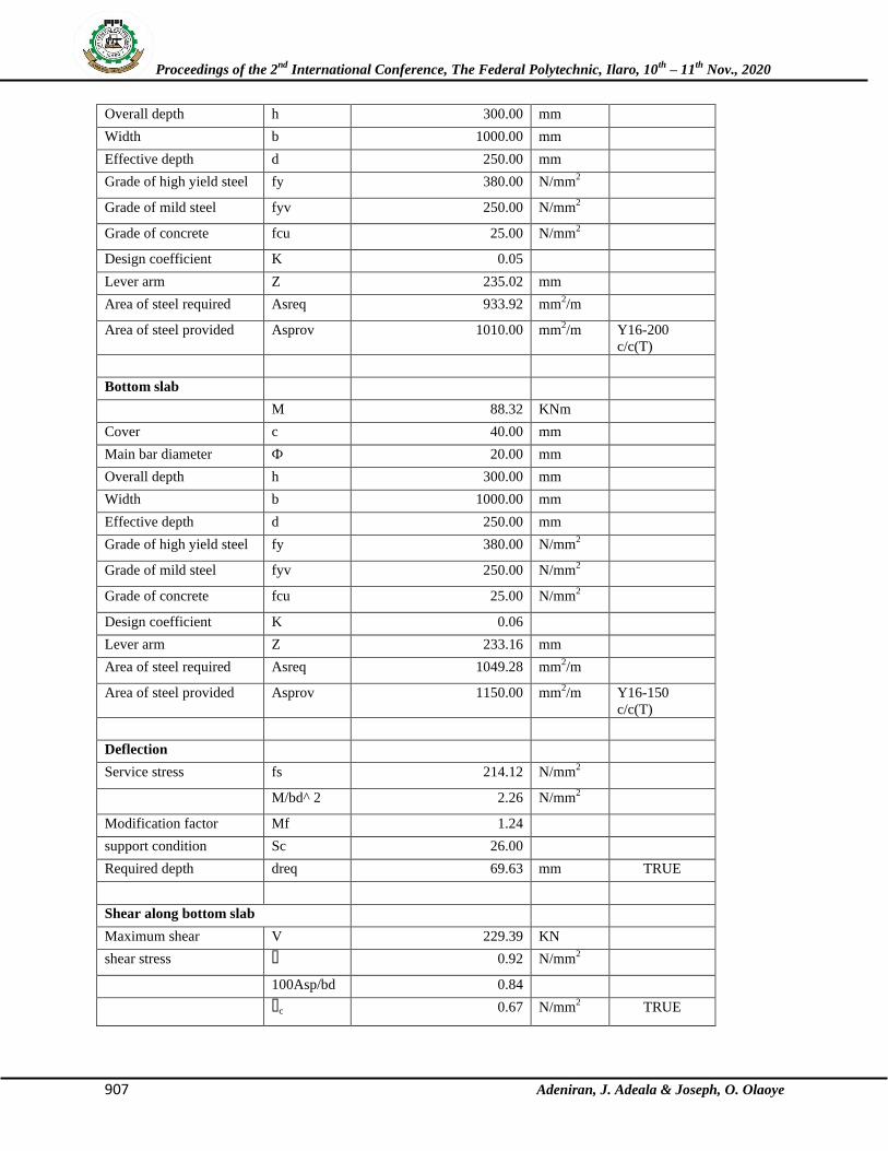
Support reinforcement
for top slab
M 79.23 KNm
Cover c 40.00 mm
Main bar diameter Ф 20.00 mm
Proceedings of the 2nd
International Conference, The Federal Polytechnic, Ilaro, 10th
– 11th
Nov., 2020
907 Adeniran, J. Adeala & Joseph, O. Olaoye
Overall depth h 300.00 mm
Width b 1000.00 mm
Effective depth d 250.00 mm
Grade of high yield steel fy 380.00 N/mm2
Grade of mild steel fyv 250.00 N/mm2
Grade of concrete fcu 25.00 N/mm2
Design coefficient K 0.05
Lever arm Z 235.02 mm
Area of steel required Asreq 933.92 mm2/m
Area of steel provided Asprov 1010.00 mm2/m Y16-200
c/c(T)
Bottom slab
M 88.32 KNm
Cover c 40.00 mm
Main bar diameter Ф 20.00 mm
Overall depth h 300.00 mm
Width b 1000.00 mm
Effective depth d 250.00 mm
Grade of high yield steel fy 380.00 N/mm2
Grade of mild steel fyv 250.00 N/mm2
Grade of concrete fcu 25.00 N/mm2
Design coefficient K 0.06
Lever arm Z 233.16 mm
Area of steel required Asreq 1049.28 mm2/m
Area of steel provided Asprov 1150.00 mm2/m Y16-150
c/c(T)
Deflection
Service stress fs 214.12 N/mm2
M/bd^2 2.26 N/mm2
Modification factor Mf 1.24
support condition Sc 26.00
Required depth dreq 69.63 mm TRUE
Shear along bottom slab
Maximum shear V 229.39 KN
shear stress ɤ 0.92 N/mm2
100Asp/bd 0.84
ɤc 0.67 N/mm2 TRUE
Proceedings of the 2nd
International Conference, The Federal Polytechnic, Ilaro, 10th
– 11th
Nov., 2020
908 Adeniran, J. Adeala & Joseph, O. Olaoye
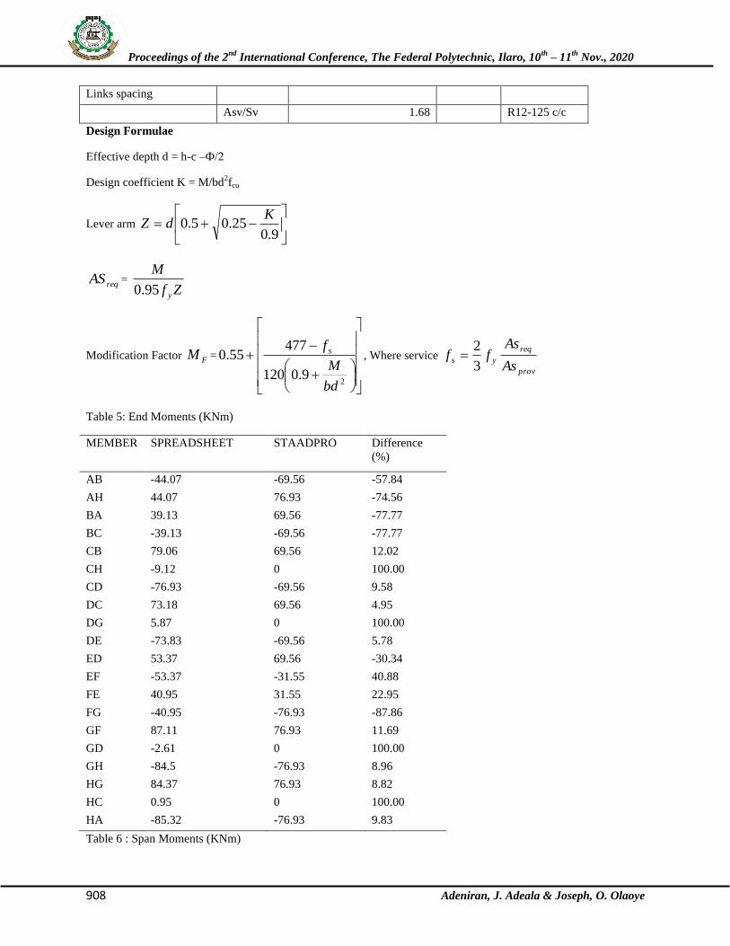
Links spacing
Asv/Sv 1.68 R12-125 c/c
Design Formulae
Effective depth d = h-c –Ф/2
Design coefficient K = M/bd2fcu
Lever arm
9.025.05.0
KdZ
reqAS = Zf
M
y95.0
Modification Factor FM =
29.0120
47755.0
bd
M
f s, Where service
prov
req
ysAs
Asff
3
2
Table 5: End Moments (KNm)
MEMBER SPREADSHEET STAADPRO Difference
(%)
AB -44.07 -69.56 -57.84
AH 44.07 76.93 -74.56
BA 39.13 69.56 -77.77
BC -39.13 -69.56 -77.77
CB 79.06 69.56 12.02
CH -9.12 0 100.00
CD -76.93 -69.56 9.58
DC 73.18 69.56 4.95
DG 5.87 0 100.00
DE -73.83 -69.56 5.78
ED 53.37 69.56 -30.34
EF -53.37 -31.55 40.88
FE 40.95 31.55 22.95
FG -40.95 -76.93 -87.86
GF 87.11 76.93 11.69
GD -2.61 0 100.00
GH -84.5 -76.93 8.96
HG 84.37 76.93 8.82
HC 0.95 0 100.00
HA -85.32 -76.93 9.83
Table 6 : Span Moments (KNm)
Proceedings of the 2nd
International Conference, The Federal Polytechnic, Ilaro, 10th
– 11th
Nov., 2020
909 Adeniran, J. Adeala & Joseph, O. Olaoye
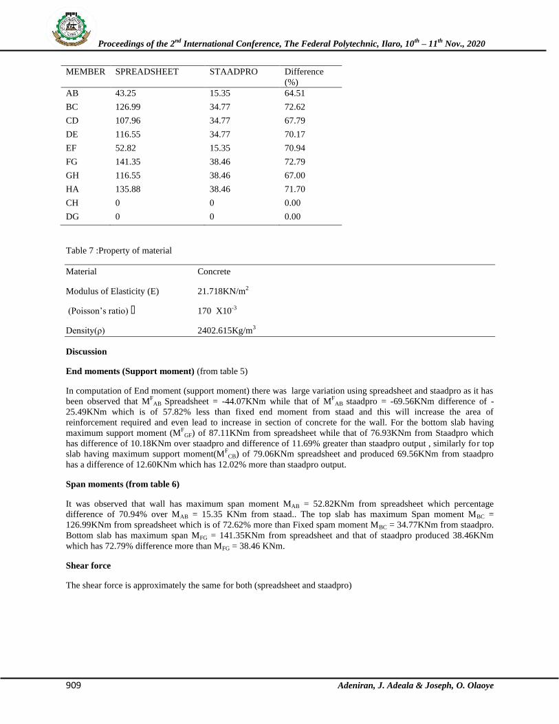
MEMBER SPREADSHEET STAADPRO Difference
(%)
AB 43.25 15.35 64.51
BC 126.99 34.77 72.62
CD 107.96 34.77 67.79
DE 116.55 34.77 70.17
EF 52.82 15.35 70.94
FG 141.35 38.46 72.79
GH 116.55 38.46 67.00
HA 135.88 38.46 71.70
CH 0 0 0.00
DG 0 0 0.00
Table 7 :Property of material
Material Concrete
Modulus of Elasticity (E) 21.718KN/m2
(Poisson’s ratio) ɤ 170 X10-3
Density(ρ) 2402.615Kg/m3
Discussion
End moments (Support moment) (from table 5)
In computation of End moment (support moment) there was large variation using spreadsheet and staadpro as it has
been observed that MF
AB Spreadsheet = -44.07KNm while that of MF
AB staadpro = -69.56KNm difference of -
25.49KNm which is of 57.82% less than fixed end moment from staad and this will increase the area of
reinforcement required and even lead to increase in section of concrete for the wall. For the bottom slab having
maximum support moment (MF
GF) of 87.11KNm from spreadsheet while that of 76.93KNm from Staadpro which
has difference of 10.18KNm over staadpro and difference of 11.69% greater than staadpro output , similarly for top
slab having maximum support moment(MF
CB) of 79.06KNm spreadsheet and produced 69.56KNm from staadpro
has a difference of 12.60KNm which has 12.02% more than staadpro output.
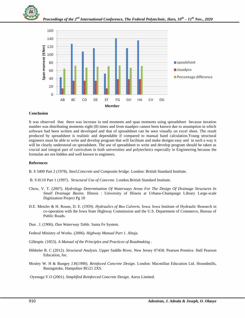
Span moments (from table 6)
It was observed that wall has maximum span moment MAB = 52.82KNm from spreadsheet which percentage
difference of 70.94% over MAB = 15.35 KNm from staad.. The top slab has maximum Span moment MBC =
126.99KNm from spreadsheet which is of 72.62% more than Fixed spam moment MBC = 34.77KNm from staadpro.
Bottom slab has maximum span MFG = 141.35KNm from spreadsheet and that of staadpro produced 38.46KNm
which has 72.79% difference more than MFG = 38.46 KNm.
Shear force
The shear force is approximately the same for both (spreadsheet and staadpro)
Proceedings of the 2nd
International Conference, The Federal Polytechnic, Ilaro, 10th
– 11th
Nov., 2020
910 Adeniran, J. Adeala & Joseph, O. Olaoye
Conclusion
It was observed that there was increase in end moments and span moments using spreadsheet because iteration
number was distributing moments eight (8) times and from staadpro cannot been known due to assumption in which
software had been written and developed and that of spreadsheet can be seen visually on excel sheet. The result
produced by spreadsheet is realistic and dependable if compared to manual hand calculation.Young structural
engineers must be able to write and develop program that will facilitate and make designs easy and in such a way it
will be clearly understood on spreadsheet. The use of spreadsheet to write and develop program should be taken as
crucial and integral part of curriculum in both universities and polytechnics especially in Engineering because the
formulae are not hidden and well known to engineers.
References
B. S 5400 Part 2 (1978). Steel,Concrete and Composite bridge. London: British Standard Institute.
B. S 8110 Part 1 (1997). Structural Use of Concrete. London.British Standard Institute.
Chow, V. T. (2007). Hydrology Determination Of Waterways Areas For The Design Of Drainage Structures In
Small Drainage Basins. Illinois : University of Illinois at Urbana-Champaign Library Large-scale
Digitization Project Pg 18
D.E. Metzler & H. Rouse, D. E. (1959). Hydraulics of Box Culverts. Iowa: Iowa Institute of Hydraulic Research in
co-operation with the Iowa State Highway Commission and the U.S. Department of Commerce, Bureau of
Public Roads.
Dun . J. (1906). Dun Waterway Table. Santa Fe System.
Federal Ministry of Works. (2006). Highway Manual Part 1. Abuja.
Gillespie. (1853). A Manual of the Principles and Practices of Roadmaking .
Hibbeler R. C (2012). Structural Analysis. Upper Saddle River, New Jersey 07458: Pearson Prentice. Hall Pearson
Education, Inc.
Mosley W. H & Bungey J.H(1990). Reinfoced Concrete Design. London: Macmillan Education Ltd. Houndmills,
Basingstoke, Hampshire RG21 2XS.
Oyenuga V.O (2001). Simplified Reinforced Concrete Design. Asros Limited.

Proceedings of the 2nd
International Conference, The Federal Polytechnic, Ilaro, 10th
– 11th
Nov., 2020
911 Adeniran, J. Adeala & Joseph, O. Olaoye
Rajput R.K (2008). Strength of Materials. Ramnagar, New Delhi: S.Chand & Company Ltd.
Simpson D. (2014). In Defence of the Rational Method. 3rd National Conference on Urban Water Management (pp.
13-17). Brisbane: City Projects Office, Brisbane City Council, GPO Box 2567, Brisbane, Qld 4001
Steedman, C. E. (1999). Reinforced Concrete Designer's Handbook. 11 New Fetter Lane, London EC4P 4EE: E &
FN Spon, Taylor & Francis Group.