Embed Size (px)
Citation preview
Comparing Data Sources for Condition Monitoring SuitabilityM. Fromberger, S. Sendlbeck, M. Rothemund, J. Götz,M. Otto and K. Stahl
IntroductionIn our industrialized world, power transmissions form an essential com-ponent of many machines that enable our way of living; machines are part of human agriculture, mobility, civil engi-neering, electricity generation or medi-cine, to name but a few.
Many of these power transmissions rely on gears as a main element. A big part of this huge amount of gears con-sists of cylindrical gears with involute tooth flank shapes.
The applications these gears are part of vary widely with regard to cost, transmit-ted power and consequences of failure. These aspects — among others — also in-fluence the maintenance strategy that is applied to a given gear set.
Figure 1 shows the service life of a machine part and shows when three different maintenance concepts be-come active during the part’s life.
Different strategies of maintenance exist (Refs. 7, 10):
Preventive maintenance covers con-cepts in which parts are replaced or re-paired according to a schedule; gener-ally, without the machine or the part being critically damaged. This ap-proach is often used when failure has severe consequences and monitoring
the actual condition of the machine is chosen not to be done.
Corrective maintenance covers ap-proaches that react on failures. A part or machine is repaired or replaced when the end of life of a machine or part is reached. This often is used for appli-cations where stand-still has no severe consequences or where failure of single parts is non-critical due to redundancy.
Condition-based maintenance on the other hand tries to identify the cur-rent state and/or the remaining service life of a machine or part as accurate as possible, thus allowing for an op-timized usage of the available service life. Opposed to the other two concepts, condition-based maintenance requires detailed state knowledge, often ac-quired by means of sensors.
Gear Condition Monitoring and Gear Damage Detection
This section illustrates the boundary conditions and relevant mechanisms that come into play if condition-based maintenance is to be applied to cylindri-cal involute gears, and how signals can be processed for condition monitoring.
Basics of involute gears and their vibration excitation behavior. As mentioned, the dominant flank shape
of gears is the involute. The kinemat-ics of an involute-shaped gear pair al-lows for a uniform transmission of the rotational movement (i.e. — zero trans-mission error) of the driving gear to the driven gear — given that deflection and deviations are disregarded.
Generally, real involute gear pairs ex-cite vibrations when operating under load. Mounting and manufacturing deviations influence this behavior, but even perfectly involute-shaped gear pairs excite vibrations due to time-vary-ing gear mesh stiffness and the corre-sponding elastic deflection. This mesh stiffness is well-described and under-stood (Ref. 9), and depends on various influence parameters, such as number of teeth pairs in contact, bending lever, radii of curvature at current mesh posi-tion, gear macro geometry (face width, tooth height, tooth thickness, etc.) and flank micro geometry (flank shape de-viations and also intentional modifica-tions (Ref. 13).
This time-varying gear mesh stiffness results in a time-varying loaded trans-mission error (LTE), which more or less corresponds to the vibration excitation of a gear mesh, depending on the dy-namic operating point of the system.
Figure 2 shows a transverse section of a spur gear mesh for two meshing po-sitions. The upper-left mesh is in a po-sition where just one pair of teeth is in contact. The upper-right image shows the same mesh in a different position where two tooth pairs are in contact.
The diagram below those two mesh-ing images shows the course of mesh stiffness and LTE, with the two shown discrete meshing positions marked as vertical lines.
This paper was first presented at the International VDI Conference on Gears 2019, 3rd International Conference on High Performance Plastic Gears 2019, 3rd International Conference on Gear Production 2019, Garching/Munich (VDI-Berichte 2355, 2019, VDI Verlag GmbH, Page 257–268)”
Figure 1 Different maintenance approaches.
42 Power Transmission Engineering ]————WWW.POWERTRANSMISSION.COMSEPTEMBER 2020
TECHNICAL

The vibration measured at the gear-box case can be composed by many dif-ferent vibration sources, e.g. — more than one gear stage (Ref. 14).
Not only manufacturing deviations of the gear flank shape, along with inten-tional deviations from the ideal involute to positively influence excitation behav-ior (Ref. 6), but also flank shape changes that occur during operation (e.g. — due to running-in and especially due to damages) have impact on the vibra-tion excitation behavior of a gear mesh. Consequently, vibration excitation of gears can be relevant for noise (and thus can be a design criterion for ap-plications relevant to human audibility, e.g. — automotive gearboxes (Ref. 2)) as well as for condition monitoring. Using gear-excited vibration to monitor gear condition has been under research for decades, with researchers often special-izing on specific damage mechanisms, e.g. — wear or scuffing (Refs. 1, 4).
Figure 3 shows a selection of gear damage mechanisms relevant in prac-tice with example photographs and some of their properties. Detailed de-scriptions of many relevant gear dam-age types are found in ISO 10825 (Ref. 5).
This and the generally simple appli-cation of picking up acceleration sig-nals are two reasons why many gear condition monitoring approaches in research, as well as in industrial prac-tice, rely on vibration/acceleration data as main measurement value.
Data acquisition and signal pro-cessing. Acceleration signals are in practice often accompanied by vari-ous kinds of angular data, ranging from simple shaft speeds (i.e. — tacho sig-nals) to full-fledged high-resolution and high-frequency absolute angular position signals of the shafts of a to-be-monitored gear stage.
Having additional angular data en-ables various processing techniques for the acceleration data. One example is applying order tracking to eliminate cy-clic irregularity by transforming acceler-ation time-series into angle-series. This is the standard approach of order track-ing, although tacho-less order tracking techniques do exist (Refs. 8, 12).
Another example is tooth-spe-cific condition monitoring. Using sufficiently precise angular data,
acceleration signals can be split into per-tooth signals. These sub signals can then be compared with regard to e.g., their signal power (Ref. 3). This al-lows for detection of damage that oc-curs on single teeth (e.g., pitting) and not nearly uniformly over all teeth (e.g., wear). This technique has the benefit of not needing external references (such as “passed” EOL test measurements), as the reference for each tooth can be e.g., the mean per-tooth signal power of the gear itself.
Choosing the right sensor equip-ment is not trivial. Available accelera-tion sensors vary in many properties. Some of these properties are suitabil-ity for intended condition monitoring
application (frequency response, fre-quency range, sample rate), require-ment for supply current; shock, temper-ature and chemical resistance, and cost.
When deciding about angular infor-mation sources, similar considerations are required; if cyclic irregularity is small, simple tacho signals may suffice. If the machine in question is operat-ing highly dynamic, more samples-per-rotation than just one or few (as often with tacho signals) may be required, directing the choice towards high-end angle encoders.
When considering angle encoders, the choice absolute vs. incremental must be made; incremental encoders can be very accurate, but limited with
Figure 2 Meshing positions and corresponding mesh stiffness and LTE.
Figure 3 Summary of typical gear damage mechanisms and some of their properties.
43Power Transmission EngineeringSEPTEMBER 2020
regard to rotational speed (Ref. 11).Absolute encoders allow for tracking
absolute angle position over long times without having to reference to addi-tional zero-pass signals or having to re-liably add up increment counts.
Comparison of a Low-End and a High-End Sensor Setup
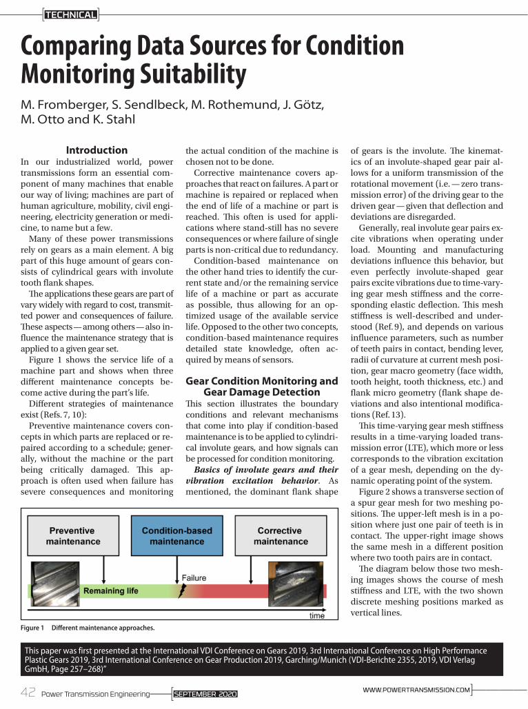
Figures 4 and 5 illustrate the DAQ sys-tems used for the tests.
The higher-end DAQ system was cho-sen to provide maximized accuracies and sample rates, using angle sensor
used in e.g., tool machines, and accel-erations sensors at the upper end of the market spectrum. The sensors are cou-pled with low-noise acquisition hard-ware capable of matching the sensor specs. The acceleration sensor has been screw-mounted directly into the bear-ing cover of the gearbox to provide best coupling stiffness and a short trans-fer path towards the point of excitation (i.e. — the gear mesh).
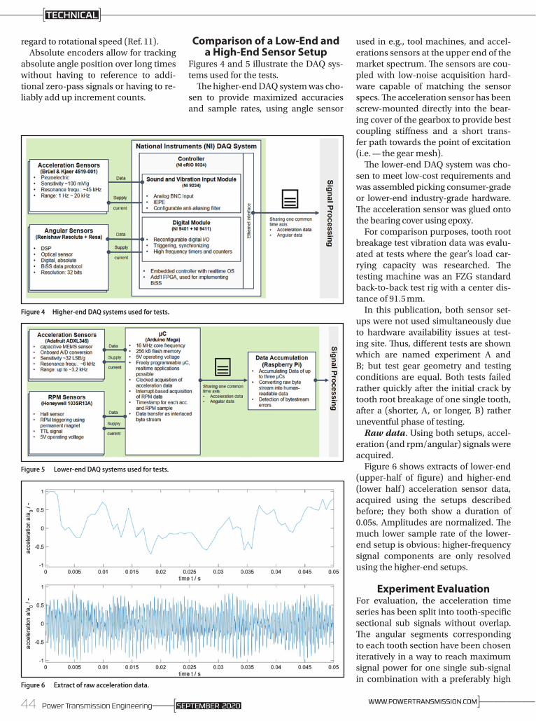
The lower-end DAQ system was cho-sen to meet low-cost requirements and was assembled picking consumer-grade or lower-end industry-grade hardware. The acceleration sensor was glued onto the bearing cover using epoxy.
For comparison purposes, tooth root breakage test vibration data was evalu-ated at tests where the gear’s load car-rying capacity was researched. The testing machine was an FZG standard back-to-back test rig with a center dis-tance of 91.5 mm.
In this publication, both sensor set-ups were not used simultaneously due to hardware availability issues at test-ing site. Thus, different tests are shown which are named experiment A and B; but test gear geometry and testing conditions are equal. Both tests failed rather quickly after the initial crack by tooth root breakage of one single tooth, after a (shorter, A, or longer, B) rather uneventful phase of testing.
Raw data. Using both setups, accel-eration (and rpm/angular) signals were acquired.
Figure 6 shows extracts of lower-end (upper-half of figure) and higher-end (lower half) acceleration sensor data, acquired using the setups described before; they both show a duration of 0.05s. Amplitudes are normalized. The much lower sample rate of the lower-end setup is obvious: higher-frequency signal components are only resolved using the higher-end setups.
Experiment EvaluationFor evaluation, the acceleration time series has been split into tooth-specific sectional sub signals without overlap. The angular segments corresponding to each tooth section have been chosen iteratively in a way to reach maximum signal power for one single sub-signal in combination with a preferably high
Figure 4 Higher-end DAQ systems used for tests.
Figure 5 Lower-end DAQ systems used for tests.
Figure 6 Extract of raw acceleration data.
44 Power Transmission Engineering ]————WWW.POWERTRANSMISSION.COMSEPTEMBER 2020
TECHNICAL
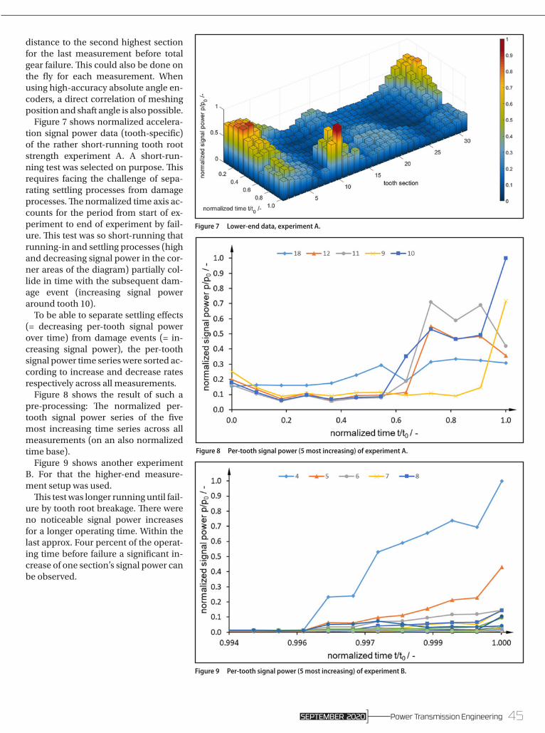
distance to the second highest section for the last measurement before total gear failure. This could also be done on the fly for each measurement. When using high-accuracy absolute angle en-coders, a direct correlation of meshing position and shaft angle is also possible.
Figure 7 shows normalized accelera-tion signal power data (tooth-specific) of the rather short-running tooth root strength experiment A. A short-run-ning test was selected on purpose. This requires facing the challenge of sepa-rating settling processes from damage processes. The normalized time axis ac-counts for the period from start of ex-periment to end of experiment by fail-ure. This test was so short-running that running-in and settling processes (high and decreasing signal power in the cor-ner areas of the diagram) partially col-lide in time with the subsequent dam-age event (increasing signal power around tooth 10).
To be able to separate settling effects (= decreasing per-tooth signal power over time) from damage events (= in-creasing signal power), the per-tooth signal power time series were sorted ac-cording to increase and decrease rates respectively across all measurements.
Figure 8 shows the result of such a pre-processing: The normalized per-tooth signal power series of the five most increasing time series across all measurements (on an also normalized time base).
Figure 9 shows another experiment B. For that the higher-end measure-ment setup was used.
This test was longer running until fail-ure by tooth root breakage. There were no noticeable signal power increases for a longer operating time. Within the last approx. Four percent of the operat-ing time before failure a significant in-crease of one section’s signal power can be observed.
Figure 9 Per-tooth signal power (5 most increasing) of experiment B.
Figure 7 Lower-end data, experiment A.
Figure 8 Per-tooth signal power (5 most increasing) of experiment A.
45Power Transmission EngineeringSEPTEMBER 2020

Dipl.-Ing., Max Fromberger studied mechanical engineering (2006–2012) at TU Munich. He was a research associate (2013–2016) at the Gear Research Centre (FZG) of TU Munich. Since 2016, Fromberger has been Team Leader/Software at the Gear Research Centre (FZG) of TU Munich.
M.Sc. Stefan Sendlbeck studied mechanical engineering at TU Munich (2011–2017). Since 2018, Sendlbeck has worked as a research associate at the Gear Research Centre (FZG) of TU Munich.
M.Sc., Markus Rothemund earned his bachelor’s degree in mechanical engineering (2011–2015) at TU Munich, and his masters at TU Munich (2015–2018). Since 2019 Rothemund has worked as a research associate at the Gear Research Centre (FZG) of TU Munich.
Joshua Götz received his Master Degree in Mechanical Engineering in 2015 at the Technical University of Munich (TUM). He is a research associate and team leader for gear dynamics in the simulation and verification of gearbox systems group at FZG. Götz’s field of study is the excitation behavior of planetary gear sets.
Dr. Michael Otto joined FZG in 2000 as a research assistant and gained his position as Head of department in 2006. He holds a PhD in mechanical engineering; the focus of his research activities was load distribution and tooth root carrying capacity. Current research activities include gear geometry, tooth contact analysis and gearbox-related NVH. Another main topic is deformation and stress analysis of supporting shafts and bearings in the gearbox. He drives the development of various scientific programs that are available for companies that are member of the FVA (German Research Association for Gears and Transmissions). Otto is head of the department ‘calculation and verification of transmission systems’ at the Gear Research Center (FZG), Prof. K. Stahl, TU München.
Prof. Dr.-Ing. Karsten Stahl has since 2011 been Full Professor, Institute for Machine Elements, Technical University of Munich, and the Director Gear Research Centre (FZG). He studied at the Technical University of Munich (TUM) beginning in 1989, with a focus on design and development, receiving his Final Mechanical Engineering Degree (Dr.-Ing) there in 1994. In 2001, he received his Doctorate TUM with the topic: Pitting Resistance of Carburized Spur and Helical Gears. Among his responsibilities during his Professorship: 2009–2010 — Head of Advanced Engineering and Innovation Management, Powertrain and Driving Dynamic Systems, BMW Group, Munich; 2007–2009 — Head of Validation Driving Dynamics and Powertrain, BMW Group, Oxford, UK; 2006–2007 — Head of Quality and QMT MINI Transmission, MINI Plant, BMW Group, Oxford, UK; 2003–2006 — Head of Prototyping, Gear Technology and Methods, BMW Group, Dingolfing; 2001–2003 — Development Engineer in Gear Production, BMW Group, Dingolfing; and 1994–2000 — Scientific Research Assistant (PhD candidate) at Gear Research Centre (FZG), TUM. Prominent among his Professional Activities: Since 2020 DFG: Member of Review Board 402-01; 2016-2018 AiF: Member of Review Board 4. His many honors and awards include (2019) VDMA Faculty Teaching Concept Award, “Bestes Maschinenhaus”; (2019) VDMA Faculty Teaching Concept Award; and (2019) Student Award “Goldene Lehre,” Best course of lectures in MW-Bachelor; and (2005) VDI Ring of Honors Award; he has chaired and participated in numerous international conferences, particularly for VDI Gearing Conferences. Stahl’s Editorial and many other activities (too numerous to list all here) include: Springer-Nature: Forschung im Ingenieurwesen, journal, Editor in Chief ASME: Journal of Vibration and Acoustics (JVA), Associate Editor Inderscience: International Journal of Powertrains (IJPT), Member of the Editorial Board EDP Sciences: International Journal of Mechanics & Industry, and Editor Tecniche Nuove: Organi di Trasmissione.
© 2020 Motion Industries, Inc.
https://motionind.biz/3a74PRD
Only Fenner Drives delivers a product offering that
combines versatile installation, design flexibility and extra
heavy-duty capacity — such as our B106 for Drum
Rollers and thin-walled hub applications.
You can find B-LOC Keyless Locking Devices
at your local Motion Industries location. Our
local sales and service specialists are experts
in providing application and technical
solutions, with the choices and expertise
you need to stay up and running.
Scan Now to Learn More
B-LOC Keyless Bushing
condition monitoring
For Related Articles Search
at www.powertransmission.com
ConclusionSeveral conclusions can be drawn by looking at these two tests’ results:• Significant changes of relative per-
tooth signal power observable in both setups
• Signal-to-noise ratio is significantly better when using the higher-end setup (see stable signal power phase at left of Fig. 9)
• Isolation of angular position contributing most power more precisely with higher-end setup
• Pre-selecting tooth signals by sorting the sub-signals (most increasing power first) allows isolating settling effects from damage, as long as one of the following is true:
» damage signal power contribu-tion is significantly larger then signal power contribution of pre-settling state
» locations of damages are sepa-rable from the location of pre-settling signal power contribut-ing locations
We plan to assemble and evalu-ate a larger database of both kinds of data. Additionally, evaluating data of the exact same tests using both mea-surement setups simultaneously is planned.
For more information.Questions or comments regarding this paper? Contact M. Fromberger at [email protected]
References1. Amarnath M. and C. Sujatha. (2015)
“Surface Contact Fatigue Failure Assessment in Spur Gears Using Lubricant Film Thickness and Vibration Signal Analysis,” Tribol Trans 58(2):327–336.
2. Bihr J., M. Heider, M. Otto, K. Stahl, T. Kume and M. Kato. (2014) “Gear Noise Prediction in Automotive Transmissions,” Int Gear Conf. 1:457–465.
3. Fromberger, M.L., B. Kohn, T. Utakapan, M. Otto Mand K. Stahl. (2016) Condition Monitoring by Position Encoders. Inter-noise Noise-con Congr Conf Proc 253(1):7451–7459.
4. Hu, C., W.A. Smith, R.B.Randall and Z. Peng. (2016) Development of a Gear Vibration Indicator and its Application in Gear Wear Monitoring,” Mech Syst Signal Process 76:319–336.
5. ISO 10 825. Gears — Wear and Damage to Gear Teeth — Terminology, ISO, 1995.
6. Kohn B. T. Utakapan, M. Fromberger, M. Otto and K. Stahl. “Flank Modifications for Optimal Excitation Behavior,” In: Forsch im Ingenieurwesen 81(2–3), pp. 65–71, 2017.
7. Kolerus J. and J. Wassermann. (2017) Zustandsüberwachung von Maschinen, Expert-Verl, Renningen.
8. Lu S. Y. Qin, J. Hang, B. Zhang and Q. Wang. (2018) Adaptively Estimating Rotation Speed from DC Motor Current Ripple for Order Tracking and Fault
Diagnosis,” IEEE Trans Instrum Meas 9(9):1–13
9. Otto, M., M. Fromberger and K. Stahl. (2016)
10. Die Verzahnungssteifigkeit in Berechnung und Experiment, In SMK 2016-Schweizer Maschinenelemente Kolloquium. TUD press, Dresden, p 33–44.
11. Randall, R.B. (2011) Vibration-Based Condition Monitoring, Wiley, Chichester (UK).
12. Remond, D. (1998) “Practical Performances of High-Speed Measurement of Gear Transmission Error or Torsional Vibrations with Optical Encoders,” Meas. Sci. Technol. 9(3):347–353.
13. Schmidt, S., P.S. Heyns and J.P. De Villiers. (2018) “A Tacho-less Order Tracking Methodology Based on a Probabilistic Approach to Incorporate Angular Acceleration Information into the Maxima Tracking Process,” Mech. Sys. and Sig. Proc. 100:630–646.
14. Utakapan, T., M.L. Fromberger, M. Heider, M. Otto, B-R. Höhn and K. Stahl. (2016) “Measurement of Gear Noise Behavior for Different Micro-Geometries, Internoise Conf Proc 253(2):6595–6605.
15. Utakapan T., B. Kohn, M. Fromberger, M.Otto and K. Stahl. (2018) Auswertung des Anregungsverhaltens eines Mehrstufigen Getriebes, Forsch Ingenieurwes 82(4):411–423.
46 Power Transmission Engineering ]————WWW.POWERTRANSMISSION.COMSEPTEMBER 2020
TECHNICAL