Embed Size (px)
Citation preview

Loma Linda UniversityTheScholarsRepository@LLU: Digital Archive of Research,Scholarship & Creative Works
Loma Linda University Electronic Theses, Dissertations & Projects
9-1-2013
Comparison between Ceph Analysis on LateralCephs, CBCT Scans, and MRI ScansJeffrey W. LamLoma Linda University
Follow this and additional works at: http://scholarsrepository.llu.edu/etd
Part of the Orthodontics and Orthodontology Commons, and the Other Dentistry Commons
This Thesis is brought to you for free and open access by TheScholarsRepository@LLU: Digital Archive of Research, Scholarship & Creative Works. Ithas been accepted for inclusion in Loma Linda University Electronic Theses, Dissertations & Projects by an authorized administrator ofTheScholarsRepository@LLU: Digital Archive of Research, Scholarship & Creative Works. For more information, please [email protected].
Recommended CitationLam, Jeffrey W., "Comparison between Ceph Analysis on Lateral Cephs, CBCT Scans, and MRI Scans" (2013). Loma Linda UniversityElectronic Theses, Dissertations & Projects. 130.http://scholarsrepository.llu.edu/etd/130

LOMA LINDA UNIVERSITY School of Dentistry
in conjunction with the Faculty of Graduate Studies
____________________
A Comparison between Ceph Analysis on Lateral Cephs, CBCT Scans, and MRI Scans
by
Jeffrey W. Lam
____________________
A thesis submitted in partial satisfaction of the requirements for the degree
Master of Science in Orthodontics and Dentofacial Orthopedics
____________________
September 2013

© 2013
Jeffrey W. Lam All Rights Reserved

iii
Each person whose signature appears below certifies that this thesis in his opinion is adequate, in scope and quality, as a thesis for the degree Master of Science. , Chairperson V. Leroy Leggitt, Professor of Orthodontics and Dentofacial Orthopedics James Farrage, Associate Professor of Orthodontics and Dentofacial Orthopedics Roland Neufeld, Associate Professor of Orthodontics and Dentofacial Orthopedics Gregory Olson, Assistant Professor of Orthodontics and Dentofacial Orthopedics

iv
ACKNOWLEDGEMENTS
I would like to acknowledge the members of my committee for offering their
direction and experience in the design and execution of this research. Dr. Leggitt was
especially helpful in offering advice contributing to the construction and details of the
data collection process.
I would especially like to thank Dr. Leggitt and Dr. Olson, who generously
contributed their time to tracing the cephalograms and scans. Your effort is much
appreciated. I would also like to thank Dr. Udo Oyoyo for his expertise in the area of
statistical analysis.
Finally, I would like to thank my wife Lyndsay and my two children, Ethan and
Ella. Your encouragement and support were invaluable.
v
CONTENTS
Approval Page .................................................................................................................... iii Acknowledgements ............................................................................................................ iv Contents ...............................................................................................................................v Tables ................................................................................................................................ vii Figures.............................................................................................................................. viii Abbreviations ..................................................................................................................... xi Abstract ............................................................................................................................. xii Chapter
1. Introduction ..............................................................................................................1
Statement of the Problem ...................................................................................1 Hypothesis..........................................................................................................1
2. Review of Literature ................................................................................................3
Lateral Cephalometric Analysis .........................................................................3 The Effects of Ionizing Radiation ......................................................................3 Magnetic Resonance Imaging ............................................................................4 Problems with using MR Scans for Cephalometric Analysis ............................5
3. Methods and Materials .............................................................................................7
Patient Selection .................................................................................................7 Image Capture ....................................................................................................7 Cephalometric Analysis .....................................................................................8 Pilot Study ..........................................................................................................9 Statistical Analysis ...........................................................................................16
4. Results ....................................................................................................................17
5. Discussion ..............................................................................................................76
Analysis of Measures with Minor Bias ............................................................76 Analysis of Measures with Significant Bias ....................................................78 Comparing the Results for 3 Readers and 2 Readers .......................................80

vi
Cephalometric Error .........................................................................................81 Evaluation of Clinical Viability .......................................................................81 Suggestions for Improvement ..........................................................................82
6. Conclusions ............................................................................................................84
References ..........................................................................................................................85 Appendices
A. Raw Data ...........................................................................................................88
vii
TABLES
Tables Page
1. Digitized and Constructed Landmarks for Digital Lateral Cephalogram ..............10
2. Digitized and Constructed Landmarks for CBCT and MRI ..................................11
3. Cephalometric Planes ............................................................................................12
4. Ricketts Analysis Measurements ...........................................................................13
5. Steiner Analysis Measurements .............................................................................14
6. Mean Differences and Standard Deviations for 3 Readers ....................................18
7. Mean Differences and Standard Deviations for 2 Readers ....................................19
8. Degree of Agreement for 3 Readers ......................................................................72
9. Degree of Agreement for 2 Readers ......................................................................73
10. Comparing Mean Differences for 2 and 3 Readers ..............................................74
11. Comparing Standard Deviations for 2 and 3 Readers ...........................................75

viii
FIGURES
Figures Page
1. Bland-Altman Plots for Cranial Deflection for 3 readers ......................................20
2. Bland-Altman Plots for Maxillary Depth for 3 readers .........................................21
3. Bland-Altman Plots for Facial Depth for 3 readers ...............................................22
4. Bland-Altman Plots for Facial Axis for 3 readers .................................................23
5. Bland-Altman Plots for Total Face Height for 3 readers .......................................24
6. Bland-Altman Plots for Lower Face Height for 3 readers .....................................25
7. Bland-Altman Plots for Mandibular Arc for 3 readers ..........................................26
8. Bland-Altman Plots for Mandibular Plane Angle for 3 readers ............................27
9. Bland-Altman Plots for L1 to A-Po for 3 readers ..................................................28
10. Bland-Altman Plots for U1 to A-Po for 3 readers .................................................29
11. Bland-Altman Plots for Interincisal Angle for 3 readers .......................................30
12. Bland-Altman Plots for Upper 6 to PtV for 3 readers ...........................................31
13. Bland-Altman Plots for Upper Incisor Protrusion for 3 readers ............................32
14. Bland-Altman Plots for Lower Incisor Protrusion for 3 readers ............................33
15. Bland-Altman Plots for Convexity for 3 readers ...................................................34
16. Bland-Altman Plots for Lower Lip to E-Plane for 3 readers .................................35
17. Bland-Altman Plots for SNA for 3 readers ............................................................36
18. Bland-Altman Plots for SNB for 3 readers ............................................................37

ix
19. Bland-Altman Plots for ANB for 3 readers ...........................................................38
20. Bland-Altman Plots for Upper 1 Angle for 3 readers ............................................39
21. Bland-Altman Plots for Lower 1 Angle for 3 readers ............................................40
22. Bland-Altman Plots for Occlusal Plane Angle for 3 readers .................................41
23. Bland-Altman Plots for Mandibular Plane Angle for 3 readers ............................42
24. Bland-Altman Plots for Upper 1 to NA for 3 readers ............................................43
25. Bland-Altman Plots for Lower 1 to NB for 3 readers ............................................44
26. Bland-Altman Plots for Pogonion to NB for 3 readers ..........................................45
27. Bland-Altman Plots for Cranial Deflection for 2 readers ......................................46
28. Bland-Altman Plots for Maxillary Depth for 2 readers .........................................47
29. Bland-Altman Plots for Facial Depth for 2 readers ...............................................48
30. Bland-Altman Plots for Facial Axis for 2 readers .................................................49
31. Bland-Altman Plots for Total Face Height for 2 readers .......................................50
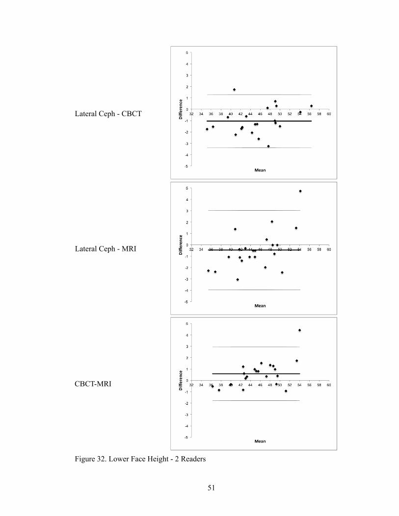
32. Bland-Altman Plots for Lower Face Height for 2 readers .....................................51
33. Bland-Altman Plots for Mandibular Arc for 2 readers ..........................................52
34. Bland-Altman Plots for Mandibular Plane Angle for 2 readers ............................53
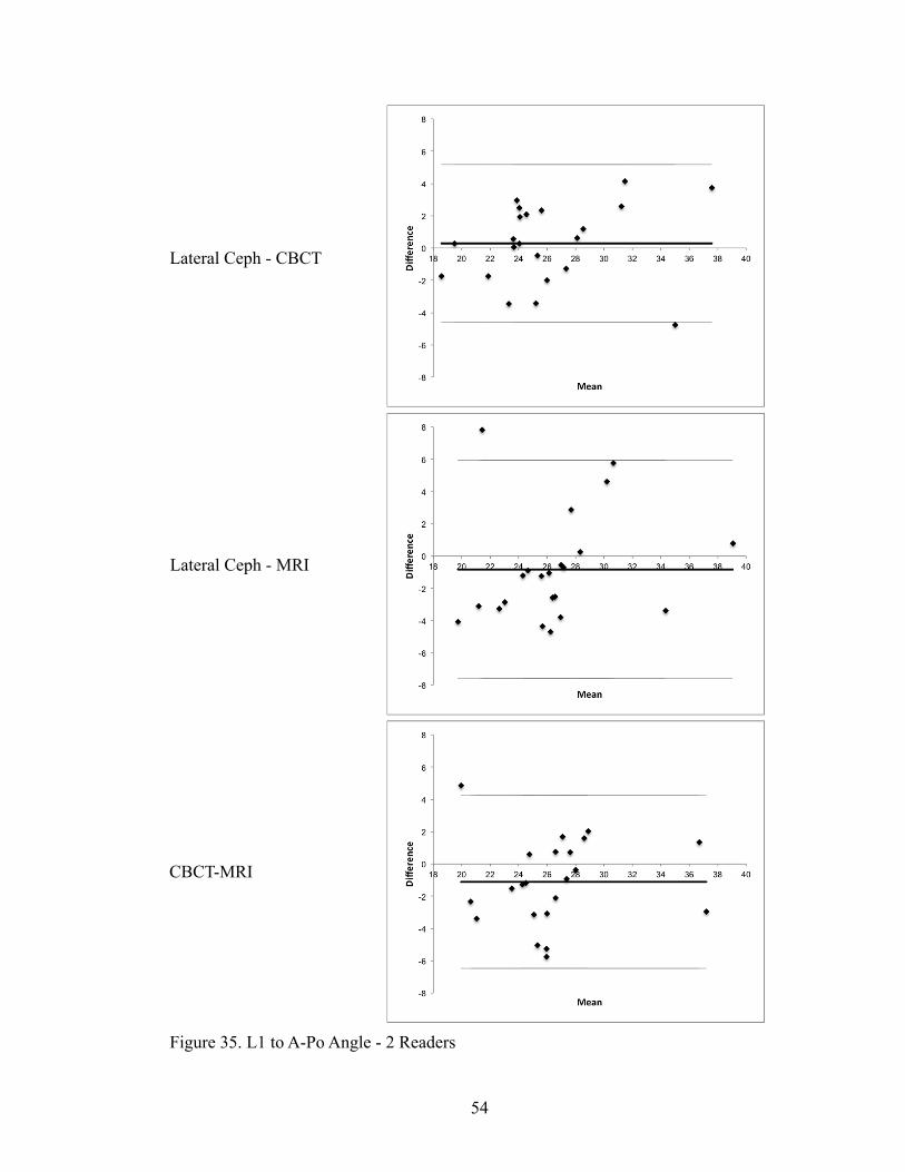
35. Bland-Altman Plots for L1 to A-Po for 2 readers ..................................................54
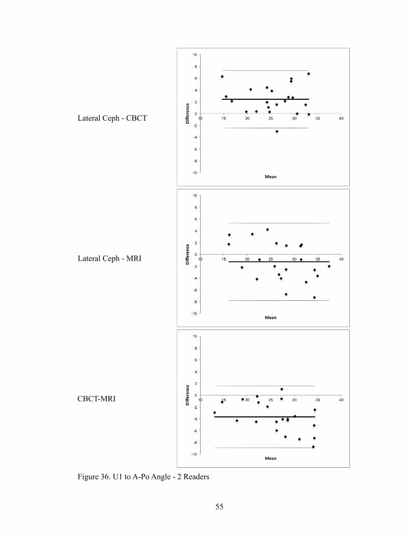
36. Bland-Altman Plots for U1 to A-Po for 2 readers .................................................55
37. Bland-Altman Plots for Interincisal Angle for 2 readers .......................................56
38. Bland-Altman Plots for Upper 6 to PtV for 2 readers ...........................................57

x
39. Bland-Altman Plots for Upper Incisor Protrusion for 2 readers ............................58
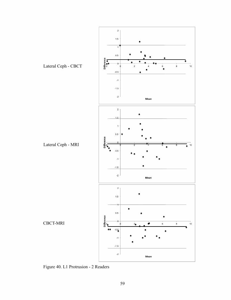
40. Bland-Altman Plots for Lower Incisor Protrusion for 2 readers ............................59
41. Bland-Altman Plots for Convexity for 2 readers ...................................................60
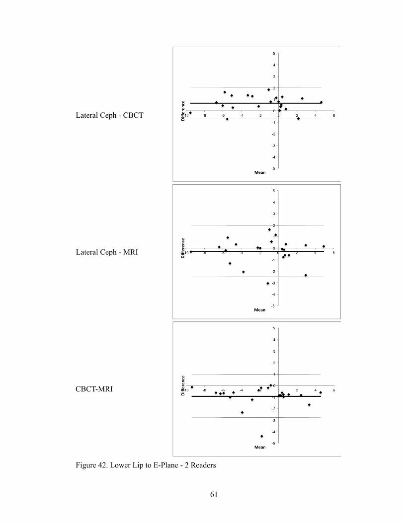
42. Bland-Altman Plots for Lower Lip to E-Plane for 2 readers .................................61
43. Bland-Altman Plots for SNA for 2 readers ............................................................62
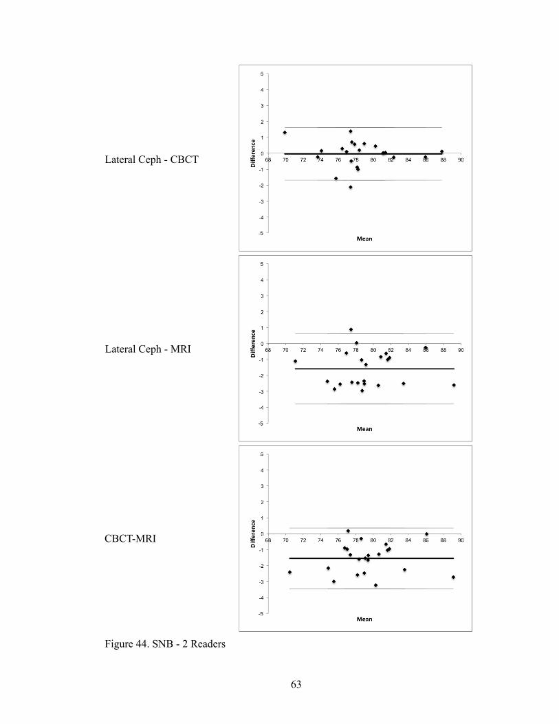
44. Bland-Altman Plots for SNB for 2 readers ............................................................63
45. Bland-Altman Plots for ANB for 2 readers ...........................................................64
46. Bland-Altman Plots for Upper 1 Angle for 2 readers ............................................65
47. Bland-Altman Plots for Lower 1 Angle for 2 readers ............................................66
48. Bland-Altman Plots for Occlusal Plane Angle for 2 readers .................................67
49. Bland-Altman Plots for Mandibular Plane Angle for 2 readers ............................68
50. Bland-Altman Plots for Upper 1 to NA for 2 readers ............................................69
51. Bland-Altman Plots for Lower 1 to NB for 2 readers ............................................70
52. Bland-Altman Plots for Pogonion to NB for 2 readers ..........................................71
53. Frankfort-Horizontal Plane Constant .....................................................................77
54. Frankfort-Horizontal Plane with Counter-Clockwise Rotation .............................77
55. SN Plane Constant .................................................................................................79
56. SN Plane with Clockwise Rotation ........................................................................79
57. Trends when Tracing Incisors ................................................................................80

xi
ABBREVIATIONS
CBCT Cone Beam Computed Tomography
MRI Magnetic Resonance Imaging
MR Magnetic Resonance
TMJ Temporomandibular Joint
DNA Deoxyribonucleic Acid
LC Lateral Cephalogram
See Tables 5 and 6 for abbreviations of cephalometric landmarks

xii
ABSTRACT OF THE THESIS
A Comparison between Ceph Analysis on Lateral Cephs, CBCT Scans, and MRI Scans
by
Jeffrey W Lam
Master of Science, Graduate Program in Orthodontics and Dentofacial Orthopedics Loma Linda University, September 2013
Dr. V. Leroy Leggitt, Chairperson
Introduction: Most current methods of obtaining images for orthodontic diagnosis
and treatment planning involve the use of ionizing radiation. Given that patients often
need records taken several times during treatment, an alternative should be found that
does not involve ionizing radiation. Magnetic resonance imaging (MRI) exists as a
possible alternative.
Purpose: The purpose of this study is to compare cephalometric measurements
obtained from lateral cephs, cone beam computed tomography (CBCT) scans, and MR
scans.
Methods: Lateral cephs, CBCTs, and MRIs were taken on 22 patients. 3 separate
readers traced the images and the data was analyzed using Bland-Altman plots.
Results: The Bland-Altman plots indicated that the correlation between the
imaging methods varied depending on the measurement. The agreement varied from very
good to statistically significant bias. However, the bias was judged to have been within
normal limits for cephalometric tracing error.
Conclusion: Under the conditions of this study, there were statistically significant
differences in some of the cephalometric measurements. However, the differences were

xiii
not clinically significant. This suggests that cephalometric data obtained from MRIs can
be used for the purposes of orthodontic diagnosis and treatment planning.

1
CHAPTER ONE
INTRODUCTION
Statement of the Problem
Lateral cephalometric analysis is an integral part of orthodontic diagnosis and
treatment planning. Currently, the most common methods of obtaining images for
cephalometric analysis involve the use of ionizing radiation, such as the traditional lateral
cephalogram and cone beam computed tomography scans. Ionizing radiation has been
shown to have potentially harmful effects, even in low doses.1 The need arises for a
method of obtaining images that does not involve the use of ionizing radiation.
One such method would be the use of magnetic resonance imaging scans, which
do not employ any ionizing radiation. However, statistically and clinically significant
differences may exist when performing cephalometric analysis on MR scans as opposed
to lateral cephs or CBCT scans.
This study was designed to evaluate if any differences exist in the cephalometric
values obtained when tracing either lateral cephs, CBCT scans, or MR scans.
Hypothesis
The null hypothesis was that there will be no difference in the cephalometric
values obtained when tracing lateral cephs and CBCT scans, lateral cephs and MR scans,
or CBCT and MR scans. The alternative hypothesis was that there will be a significant

2
difference between either lateral cephs and CBCT scans, lateral cephs and MR scans, or
CBCT and MR scans.

3
CHAPTER TWO
REVIEW OF THE LITERATURE
History of Lateral Cephalometric Analysis
A large part of the process of orthodontic diagnosis and treatment planning has
been based on the lateral cephalometric radiograph. Through the process of identification
of cephalometric landmarks and planes, an understanding of a patient’s skeletal
relationships is gathered, especially anterior-posteriorly. Growth predictions can be made
and the changes that have occurred due to treatment can be evaluated.
Traditionally, the lateral cephalogram is obtained by the standard method of
taking a profile radiograph of a patient from a set distance away using ionizing radiation.
However, in more recent times it has now also become possible to obtain lateral cephs by
using displays of multi-planar CBCT volumes.2 Recent studies have shown that there is
no statistically significant nor clinically relevant difference when tracing images from
conventional lateral cephs or images obtained from CBCT volumes.3,4 In fact, the
identification of skeletal landmarks may be even more precise when obtained from CBCT
derived images.5
The Effects of Ionizing Radiation
However, the issue remains that these methods of obtaining diagnostic images
involve the use of ionizing radiation. The effects of ionizing radiation on tissue have been

4
well documented. Studies have linked ionizing radiation exposure to DNA damage,6
chronic cell dysfunction,7 teratogenic effects,8 and cancer1 among other adverse effects.
These effects can occur at all levels of radiation, from levels as low as those
occurring with background radiation and diagnostic radiology to the higher levels
associated with radiotherapy and nuclear medicine.1 There are also patients in whom the
use of any ionizing radiation is contraindicated, such as patients who have gone through
radiotherapy in the head and neck region and are at risk for salivary gland dysfunction
and hence severe xerostomia.
Magnetic Resonance Imaging
The need arises for a method of obtaining images for diagnosis that does not
involve the use of ionizing radiation. One such alternative would be the use of magnetic
resonance imaging (MRI) as magnetic resonance (MR) scans do not involve the use of x-
rays or other types of ionizing radiation.
MR scans are obtained by creating a magnetic field in the targeted portion of the
body. The field causes the nuclei of hydrogen atoms, or protons, to align in a certain
manner. When the field is removed, the nuclei return to their original orientation,
emitting energy in forms detectable by the scanner. Different types of tissue react
differently and release energy at different levels determined by the atoms’ realignment
times. These pulses can be recognized and differentiated by the MR machine.
An image is then created where the tissues of greater proton density are shown as
whiter areas on an MR scan, and less proton dense tissues as darker areas. This allows
differentiation of the various tissues. However, it must be noted that although trabecular

5
bone is visible due to the presence of bone marrow, cortical bone is not visible on MR
scans.9 Cortical bone tissue does not respond to magnetic fields and radio pulses in the
same way as soft tissue and thus does not transmit the necessary energy pulses that the
MR machine requires for imaging. It appears as a dark space on MR scans, no different
on MR images from empty space.
Currently, MRIs are used mostly in the medical profession in the evaluation of
soft tissue but the use of MR scans in evaluation of the head and neck in dental and
orofacial issues is increasing. So far the most common dental uses have been in the
evaluation of the temporomandibular joint (TMJ).10 the patient’s airway,11 and the
orofacial musculature.12,13 However, innovative uses of MR scans to evaluate hard tissues
are starting to appear. Some examples include evaluation of the relationship of impacted
third molars to the mandibular canals in young patients14 and the use of a recently
developed MR imaging technique called SWeep Imaging with Fourier Transform
(SWIFT) to evaluate dental tissues for pathosis and healing in the field of endodontics.15
Problems with Using MR Scans for Cephalometric Analysis
There exist potential issues with using MRI derived images for orthodontic
diagnosis. MR scans are already currently in use in the cephalometric analysis of soft
tissue of the head and neck.16 However, many of the landmarks important in the
numerous types of orthodontic diagnostic analyses are based on the location of cortical
hard tissue skeletal structures, not only soft tissue. Thus the location of bony hard tissue
landmarks and planes poses a challenge due to the phenomena of cortical bone not being

6
visible on MR images.9 Despite that potential issue, MRI images have been shown to be
as capable as CBCT images in evaluating the physical dimensions of bony material.9
MR scans are affected by the presence of certain metals present in the oral cavity
or head and neck area.17 At levels of 3T and above, they can also contribute to
microleakage in dental amalgam restorations.18 Since a large percentage of patients may
already have metal dental restorations, metal implants, or already be wearing metal
orthodontic appliances, the diagnostic usefulness of these images when the patient in
question has any of those metals already present in the oral cavity may be compromised.
Besides the technical obstacles presented, there are also practical issues. One must
also consider the current high cost of taking MR scans. MR scans also require more time
to take and to process than conventional lateral cephs and CBCT images,19 so their
implementation in a clinical environment may not be straightforward. Some patients have
also reported feeling claustrophobic inside the MR scanner,20 and the noise and
movement of the machine has frightened young patients.
Despite these drawbacks, there exists a need for alternatives to imaging
techniques involving ionizing radiation should they be necessary or become more
feasible in the future.

7
CHAPTER THREE
MATERIALS AND METHODS
Patient Selection
Two relevant previous studies regarding MRI, CBCT, and lateral cephalograms
have been carried out by orthodontic residents in Loma Linda University.21,22 The studies
required each patient to have a digital lateral cephalogram, a CBCT scan, and an MRI
taken. From these previous 2 studies, 22 patients were chosen for this study according to
the following exclusion criteria:
1. No metallic dental restorations
2. No medical or dental implants
3. Not claustrophobic
4. Female subjects are not pregnant
The study received IRB approval from the Loma Linda University (LLU)
Institutional Review Board (IRB) before any images were obtained.
Image Capture
The patients were placed in maximum intercuspation and sagittal images for
comparison were taken using three different methods:
1. A digital lateral cephalogram (Orthophos XG Plus, Sirona, Bensheim,
Germany) was taken of each patient with the patient standing in an upright
position. The lateral ceph images was acquired with a standardized distance

8
of 60 inches from x-ray source to mid-sagittal plane. The Orthophos XG
Plus uses a horizontal x-ray beam for scanning and then software corrects
the data to obtain undistorted images.
2. A CBCT scan (NewTom 3G, AFP Imaging, Elmsford, New York, USA)
was taken on each patient with a 12-inch field of view (FOV) and a total
exposure time of 5.4 seconds. The images were obtained with the patients
lying prone with their faces up. Axial slices 0.5 mm thick were created and
exported in Digital Imaging and Communications in Medicine (DICOM)
format.
3. The MR scans (TIM/Trio, Siemens Medical Solutions, Erlangen, Germany)
were performed using a 3.0T MR imaging system in a 12 channel head
array coil. A T1-weighted 3D imaging sequence [Magnetization Prepared
Rapid Acquisition by Gradient Echo (MP-RAGE), TR/TE = 1950/2.26 ms]
was used to produce contiguous sagittal images of the entire head with an
isotropic resolution of 1.0x1.0x1.0 mm. The slices were also exported in
DICOM format.
Cephalometric Tracing
Three orthodontists digitized the obtained images. Prior to tracing the images, the
readers were required to undergo a calibration session to determine how the locations of
each of the landmarks should be chosen. The calibration entailed having the readers
going through landmark digitization for one complete set of patient images (lateral
cephalogram, CBCT, and MRI) together and determining how placements for each

9
landmark would be chosen. The readers then each traced a second set of images and
compared the obtained cephalometric values and tracings.
Digitization of the images was done in Dolphin Imaging software. Cephalometric
landmarks (Tables 1 and 2) were chosen to locate relevant planes (Table 3) and thus
allow calculation of 26 total Ricketts and Steiner analysis values (Tables 4 and 5) for
each image of each patient. The digitized lateral cephs were traced in 2 dimensions, and
the CBCT and MRI 3D volumes were traced in Dolphin Imaging software in the ‘3D’
setting. Readers used image optimization tools of zooming in and/or contrast modulation
as necessary for maximum accuracy.
Each reader’s obtained values were weighted equally for statistical analysis. The
images were traced in random order with no organization by patient or type of image.
Readers only traced a maximum of 10 images in any given session to avoid errors due to
fatigue.
Pilot Study
A pilot study was undertaken to discover any potential complications in landmark
location and hence determination of planes and calculation of values. There were 3 main
problems identified.
The first issue was that on a digitized lateral ceph, bilateral landmarks are
averaged and a corresponding landmark location determined by eye. However, due to
software limitations when tracing the CBCTs and MRIs in 3 dimensions only one side
could be traced at a time. To account for this, the 3 dimensional DICOM volumes were

10
Table 1: Digitized and Constructed Landmarks for Digital Lateral Cephalogram Digitized Landmarks Description
1 Porion (Pr) Averaged most lateral and superior point of the bony external auditory meatus 2 Orbitale (Or) Averaged most inferior point on the infraorbital rim
3 Pterygoid point (Pt) Averaged intersection of inferior edge of foramen rotundum and pterygomaxillary fissure
4 Sella (S) Midpoint of Sella Turcica 5 Nasion (N) Intersection of internasal and nasofrontal sutures 6 Basion (Ba) Most inferior point on the anterior margin of foramen magnum 7 DC Point (DC) Averaged midpoint of mandibular condyle along the NaBa plane 8 Tip of Nose (NT) Most prominent point at tip of nose 9 Lower Lip (LL) Most prominent point of the lower lip
10 Soft Tissue Pogonion (sPo) Most prominent point of soft tissue chin
11 B Point (B) Deepest point between pogonion and mandibular dental alveolus 12 Pogonion (Po) Most anterior point of mandibular symphysis 13 Menton (Me) Most inferior point of mandibular symphysis 14 Gonion (Go) Averaged most convex point at the posterior-inferior curve of ramus 15 Mid Ramus (R1) Averaged most concave point on anterior ramus (to construct Xi) 16 R2 (R2) Averaged most convex point on posterior border of ramus (to construct Xi) 17 Sigmoid Notch (R3) Averaged most inferior point of the sigmoid notch (to construct Xi) 18 R4 (R4) Averaged most superior point along inferior border of ramus (to construct Xi) 19 A point (A) Deepest point between ANS and dental alveolus
20 Anterior Nasal Spine (ANS) Tip of the anterior nasal spine
21 Upper 6 Occlusal (U6O) Averaged mesial-buccal cusp tip of maxillary 1st molar 22 Lower 6 Occlusal (L6O) Averaged mesial-buccal cusp tip of mandibular 1st molar 23 Upper 6 Distal (U6D) Averaged distal height of contour of maxillary 1st molar 24 Upper 6 Mesial (U6M) Averaged mesial height of contour of maxillary 1st molar 25 Lower 6 Distal (L6D) Averaged distal height of contour of mandibular 1st molar 26 Lower 6 Mesial (L6M) Averaged mesial height of contour of mandibular 1st molar 27 Lower 1 Crown (L1C) Averaged tip of crown of lower central incisor 28 Lower 1 Root (L1R) Averaged tip of root of lower central incisor 29 Upper 1 Crown (U1C) Averaged tip of crown of upper central incisor 30 Upper 1 Root (U1R) Averaged tip of root of upper central incisor 31 Gnathion (Gn) Most anterior-inferior point of the mandibular symphysis 32 Protuberance Menti (PM) Point of inflection between B and Po
Constructed Landmarks Descripton
33 Xi Point (Xi) Geometric center of box formed by R1, R2, R3, and R4
34 Constructed Gnathion (cGn) Intersection of the facial and mandibular planes
35 Center Frankfort (CF) Intersection of Frankfort and Pterygoid Vertical Planes

11
Table 2: Digitized and Constructed Landmarks for CBCT and MRI
Digitized Landmarks Description 1 Porion (Pr) Most lateral and superior points of the roofs of the bony external auditory meatus 2 Orbitale (Or) Most inferior points on the infraorbital rim 3 Pterygoid point (Pt) Intersections of inferior edge of foramen rotundum and pterygomaxillary fissure 4 Sella (S) Midpoint of Sella Turcica 5 Nasion (N) Intersection of internasal and nasofrontal sutures 6 Basion (Ba) Most inferior point on the anterior margin of foramen magnum 7 DC Point (DC) Midpoints of neck of condyle at its narrowest point when visible at slice level of Pr 8 Tip of Nose (NT) Most prominent point at tip of nose 9 Lower Lip (LL) Most prominent point of the lower lip 10 Soft Tissue Pogonion
(sPo) Most prominent point of soft tissue chin 11 B Point (B) Deepest point between pogonion and dental alveolus 12 Pogonion (Po) Most anterior point of mandibular symphysis 13 Menton (Me) Most inferior point of mandibular symphysis 14 Gonion (Go) Most convex points at the posterior-inferior curve of ramus 15 Mid Ramus (R1) Most concave points on anterior ramus (to construct Xi) 16 R2 (R2) Most convex points on posterior border of ramus (to construct Xi) 17 Sigmoid Notch (R3) Most inferior points of the sigmoid notch (to construct Xi) 18 R4 (R4) Most superior points along inferior border of ramus (to construct Xi) 19 A point (A) Deepest point between ANS and dental alveolus 20 Anterior Nasal Spine
(ANS) Tip of the anterior nasal spine 21 Upper 6 Occlusal (U6O) Mesial-buccal cusp tip of maxillary 1st molar 22 Lower 6 Occlusal (L6O) Mesial-buccal cusp tip of mandibular 1st molar 23 Upper 6 Distal (U6D) Distal height of contour of maxillary 1st molar 24 Upper 6 Mesial (U6M) Mesial height of contour of maxillary 1st molar 25 Lower 6 Distal (L6D) Distal height of contour of mandibular 1st molar 26 Lower 6 Mesial (L6M) Mesial height of contour of mandibular 1st molar 27 Lower 1 Crown (L1C) Tip of crown of lower central incisor 28 Lower 1 Root (L1R) Tip of root of lower central incisor 29 Upper 1 Crown (U1C) Tip of crown of upper central incisor 30 Upper 1 Root (U1R) Tip of root of upper central incisor 31 Gnathion (Gn) Most anterior-inferior point of the mandibular symphysis 32 Protuberance Menti (PM) Point of inflection between B and Po
Constructed Landmarks Descripton 33 Xi Point (Xi) Geometric center of box formed by R1, R2, R3, and R4 34 Constructed Gnathion
(cGn) Intersection of the facial and mandibular planes 35 Center Frankfort (CF) Intersection of Frankfort and Pterygoid Vertical Planes

12
Table 3: Cephalometric Planes Plane Description Ricketts Analysis 1 Frankfort Horizontal (FH) Plane from Pr to Or 2 Nasion to Basion (NaBa) Plane from Na to Ba 3 Nasion to A point (NA) Plane from N to A point 4 Nasion to B point (NB) Plane from N to B point 5 Facial Axis (FA) Plane from Pt to cGn 6 Facial Plane (FP) Plane from N to Po 7 Corpus Axis (CA) Plane from PM to Xi 8 Pterygoid Vertical Plane (PtV) The vertical plane through Pt perpendicular to FH plane 9 Mandibular Plane (MP) Plane from Go to Me 10 Lower Incisor Axis (L1) Plane from lower incisor incisal edge to lower incisor root tip 11 Upper Incisor Axis (U1) Plane from upper incisor incisal edge to upper incisor root tip 12 A-Po plane (A-Po) Plane from A to Po 13 Xi-ANS plane (Xi-ANS) Plane from Xi to ANS 14 Esthetic Plane (E-plane) Plane from NT to sPo Steiner Analysis 1 Sella-Nasion (SN) Plane from S to N 2 Nasion to A point (NA) Plane from N to A point 3 Nasion to B point (NB) Plane from N to B point 4 Mandibular Plane (Go-Gn) Plane from Go to Gn 5 Occlusal Plane (Occ) Plane drawn through overlapping cusps of 1st molars and 1st
premolars

13
Table 4: Ricketts Analysis Measurements Ricketts Analysis Description
Angular Measurements 1 Cranial Deflection (CD) Angle formed by NaBa and FH planes 2 Maxillary Depth (MD) Angle formed by NA and FH planes 3 Facial Depth (FD) Angle formed by N-Po and FH planes 4 Facial Axis (FA) Angle formed by NaBa and FA planes 5 Total Face Height (TFH) Angle formed by NaBa and CA planes 6 Lower Face Height (LFH) Angle formed by CA and X-ANS planes 7 Mandibular Arc (MA) 90° - Angle formed by DC-Xi-PM 8 Mandibular Plane Angle (MPA) Angle formed by FH and MP planes 9 L1 to A-Po (L1-APo) Angle formed by L1 and A-Po planes 10 U1 to A-Po (U1-APo) Angle formed by U1 and A-Po planes 11 Interincisal Angle (1/1) Angle formed by L1 and U1 axes
Linear measurements 1 Upper 6 to PtV (6-PtV) Horizontal distance from distal of the maxillary 6 to PtV 2 Upper Incisor Protrusion (U1P) Horizontal distance from tip of U1 to A-Po 3 Lower Incisor Protrusion (L1P) Horizontal distance from tip of L1 to A-Po 4 Convexity (Conv) Most prominent point at tip of nose 5 Lower Lip to E-plane (LL-EP) Most prominent point of the lower lip

14
Table 5: Steiner Analysis Measurements Steiner Analysis Description
Angular Measurements 1 SNA Angle formed by SN and NA planes 2 SNB Angle formed by SN and NB planes 3 ANB Angle formed by NA and NB planes 4 Upper 1 Angle (U1/NA) Angle formed by U1 and NA 5 Lower 1 Angle (L1/NB) Angle formed by L1 and NB 6 Occlusal Plane Angle (OPA) Angle formed by the functional occlusal plane and SN 7 Mandibular Plane Angle (GoGn-SN) Angle formed by Go-Gn and SN planes
Linear Measurements 1 Upper 1 to NA (U1-NA) Perpendicular distance from U1C to NA plane 2 Lower 1 to NB (L1-NB) Perpendicular distance from L1C to NB plane 3 Pogonion to NB (Po-NB) Perpendicular distance from Po to NB plane

15
traced twice, once for the right side and once for the left. The obtained values were then
averaged to account for any differences.
The next problem that arose was locating the landmark porion when tracing the
CBCT and MRI scans in 3D. A traditional lateral ceph offers a flattened 2 dimensional
viewpoint into the auditory canals and the most superior point is selected. However, in a
3D DICOM volume, the highest point can only be located by scrolling through the
sagittal slices. For the purposes of this study, when tracing a 3D volume porion was
defined as the most superior points of the roofs of the bony external meatus when tracing
either the right or left side.
Another issue concerned the landmark DC point. The traditional definition of DC
point in Rickett’s analysis is the midpoint of the mandibular condyle along the NaBa
plane. In a traditional lateral ceph, this point is easily identifiable after drawing the NaBa
plane. However, when tracing in 3D the NaBa plane is not viewable on the screen,
making it difficult to locate DC point according to it’s traditional definition. As such, for
the purposes of this study DC point is defined as the midpoint of the condyle at it’s
narrowest point when viewing the sagittal slice where Po is marked.
The final difficulty encountered was in the orientation of the CBCT and MRI
images. A significant number of the 3 dimensional DICOM volumes did not have a
correct patient head orientation. For the CBCT images, the head images could be
reoriented and saved in the software. However, for the MRI images, it was not possible to
reorient the volumes and save the new orientation in the software so that all 3 tracers
would have an identical head orientation. Given a choice of each tracer self-reorienting
the images or having all 3 tracers trace the images with a rotated head position, the choice

16
was made to retain the original orientation in hopes of improving agreement among the
readers.
Statistical Analysis
The results were analyzed using Bland-Altman plots to compare each of the 26
Ricketts and Steiner measurements. For each measurement, lateral ceph was compared to
CBCT and MRI, and then CBCT was compared to MRI.
17
CHAPTER FOUR
RESULTS
Results
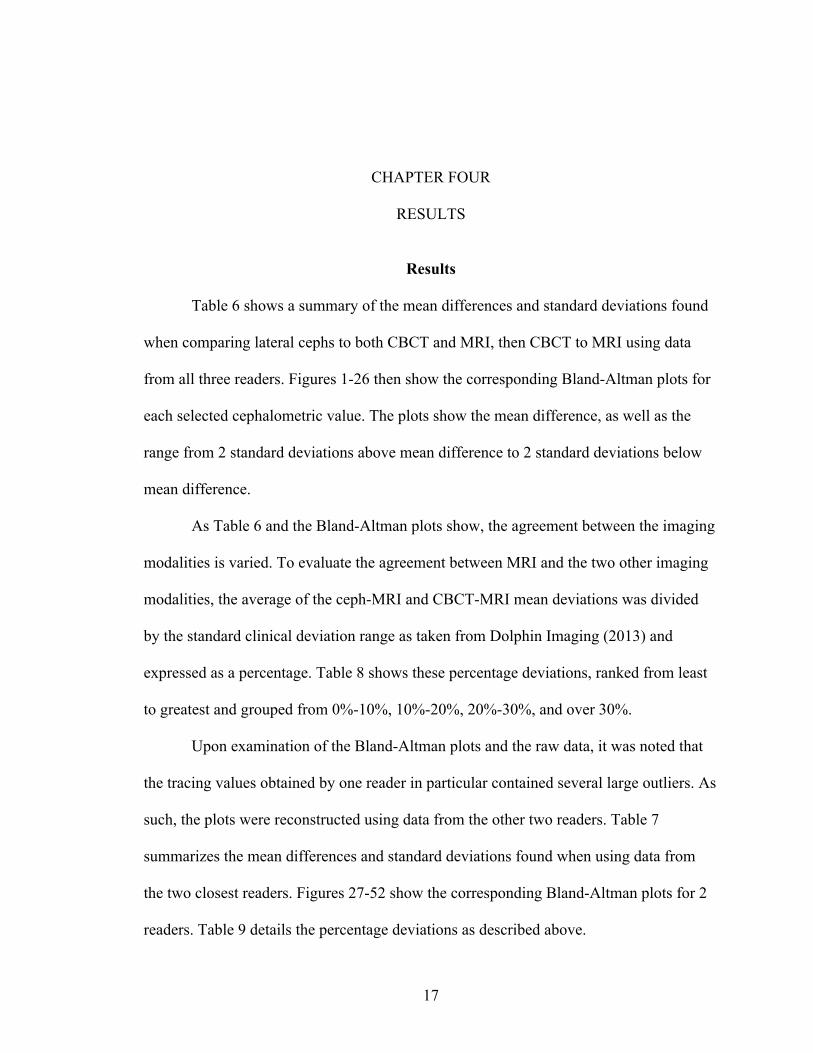
Table 6 shows a summary of the mean differences and standard deviations found
when comparing lateral cephs to both CBCT and MRI, then CBCT to MRI using data
from all three readers. Figures 1-26 then show the corresponding Bland-Altman plots for
each selected cephalometric value. The plots show the mean difference, as well as the
range from 2 standard deviations above mean difference to 2 standard deviations below
mean difference.
As Table 6 and the Bland-Altman plots show, the agreement between the imaging
modalities is varied. To evaluate the agreement between MRI and the two other imaging
modalities, the average of the ceph-MRI and CBCT-MRI mean deviations was divided
by the standard clinical deviation range as taken from Dolphin Imaging (2013) and
expressed as a percentage. Table 8 shows these percentage deviations, ranked from least
to greatest and grouped from 0%-10%, 10%-20%, 20%-30%, and over 30%.
Upon examination of the Bland-Altman plots and the raw data, it was noted that
the tracing values obtained by one reader in particular contained several large outliers. As
such, the plots were reconstructed using data from the other two readers. Table 7
summarizes the mean differences and standard deviations found when using data from
the two closest readers. Figures 27-52 show the corresponding Bland-Altman plots for 2
readers. Table 9 details the percentage deviations as described above.
18
Table 6. Mean Differences and Standard Deviations for 3 Readers
Measurement Ceph-CBCT Ceph-MRI CBCT-MRI
Mean Difference
Standard Deviation
Mean Difference
Standard Deviation
Mean Difference
Standard Deviation
(R)Cranial Deflection (º) -1.83 1.64 -1.43 2.04 0.40 1.14
(R)Maxillary Depth (FH-NA) (º) -1.27 1.32 -1.45 1.77 -0.18 1.19
(R)Facial Depth (FH-NPo) (º) -0.90 1.09 -0.54 1.56 0.37 1.06
(R)Facial Axis (NaBa-PtGn)(º) 1.92 1.02 1.09 1.19 -0.82 0.95
(R)Total Face Height (NaBa-PmXi) (º) -1.14 1.15 0.20 1.26 1.34 1.35
(R)Lower Face Height (ANS-Xi-Pm)(º) -0.98 1.40 -0.98 1.76 0.00 1.32
(R)Mandibular Arc (º) 1.10 2.61 -0.63 2.58 -1.73 2.39
(R)FMA (MP-FH) (º) 0.87 1.27 2.36 2.84 1.49 2.32
(R)L1 to A-Po (º) 0.49 2.31 -0.87 3.22 -1.36 3.03
(R)U1 to A-Po (º) 2.91 2.42 -1.12 3.50 -4.03 2.30
(R)Interincisal Angle (U1-L1) (º) -3.40 3.44 1.99 3.87 5.38 3.64
(R)U6 - PT Vertical (mm) -1.02 1.42 -1.78 2.25 -0.76 1.91
(R)U1 Protrusion (U1-APo) (mm) 0.24 0.44 -0.71 0.78 -0.95 0.63
(R)L1 Protrusion (L1-APo) (mm) 0.27 0.43 -0.32 0.63 -0.59 0.51
(R)Convexity (A-NPo) (mm) -0.38 0.54 -0.97 1.15 -0.59 0.99
(R)Lower Lip to E-Plane (mm) 0.51 1.15 -0.28 1.13 -0.79 1.20
(S)SNA (º) -0.25 0.96 -2.14 1.51 -1.89 1.32
(S)SNB (º) -0.03 0.83 -1.51 1.05 -1.48 0.94
(S)ANB (º) -0.21 0.46 -0.63 0.93 -0.42 0.88
(S)U1 - NA (º) 3.70 2.48 0.99 3.23 -2.71 2.01
(S)L1 - NB (º) -0.08 2.25 -2.13 3.15 -2.06 3.42
(S)Occ Plane to SN (º) -0.21 1.42 2.09 2.62 2.30 2.07
(S)MP - SN (º) -0.18 1.13 3.02 2.38 3.20 2.21
(S)U1 - NA (mm) 0.56 0.77 -0.02 1.26 -0.58 0.88
(S)L1 - NB (mm) 0.16 0.35 -0.55 0.69 -0.71 0.75
(S)Pog - NB (mm) 0.17 0.46 0.57 0.73 0.39 0.53

19
Table 7. Mean Differences and Standard Deviations for 2 Readers
Measurement Ceph-CBCT Ceph-MRI CBCT-MRI
Mean Difference
Standard Deviation
Mean Difference
Standard Deviation
Mean Difference
Standard Deviation
(R)Cranial Deflection (º) -1.60 1.78 -1.33 2.08 0.27 1.16
(R)Maxillary Depth (FH-NA) (º) -1.06 1.40 -1.80 2.13 -0.74 1.30
(R)Facial Depth (FH-NPo) (º) -0.81 1.31 -0.77 1.84 0.04 1.22
(R)Facial Axis (NaBa-PtGn)(º) 1.71 1.05 0.91 1.33 -0.80 0.88
(R)Total Face Height (NaBa-PmXi) (º) -1.35 1.19 0.24 1.54 1.59 1.19
(R)Lower Face Height (ANS-Xi-Pm)(º) -1.05 1.16 -0.47 1.75 0.58 1.18
(R)Mandibular Arc (º) 1.18 2.85 -0.67 2.92 -1.85 2.29
(R)FMA (MP-FH) (º) 1.01 1.45 2.92 2.40 1.91 1.75
(R)L1 to A-Po (º) 0.30 2.44 -0.83 3.38 -1.13 2.67
(R)U1 to A-Po (º) 2.41 2.42 -1.28 3.28 -3.69 2.62
(R)Interincisal Angle (U1-L1) (º) -2.70 3.31 2.11 4.11 4.81 3.96
(R)U6 - PT Vertical (mm) -0.90 1.55 -1.58 2.36 -0.67 1.76
(R)U1 Protrusion (U1-APo) (mm) 0.16 0.46 -0.56 0.87 -0.72 0.61
(R)L1 Protrusion (L1-APo) (mm) 0.24 0.44 -0.09 0.76 -0.33 0.66
(R)Convexity (A-NPo) (mm) -0.26 0.49 -1.09 1.25 -0.83 1.02
(R)Lower Lip to E-Plane (mm) 0.65 0.68 -0.27 1.12 -0.93 0.93
(S)SNA (º) -0.09 0.91 -2.24 1.59 -2.15 1.48
(S)SNB (º) -0.04 0.82 -1.59 1.10 -1.55 0.95
(S)ANB (º) -0.05 0.38 -0.65 1.03 -0.60 0.93
(S)U1 - NA (º) 3.00 2.17 0.89 2.67 -2.11 2.04
(S)L1 - NB (º) -0.22 2.56 -2.38 3.49 -2.16 3.38
(S)Occ Plane to SN (º) -0.49 1.48 0.97 2.64 1.46 1.99
(S)MP - SN (º) 0.00 1.18 3.36 1.93 3.36 1.23
(S)U1 - NA (mm) 0.40 0.77 0.19 1.25 -0.21 0.74
(S)L1 - NB (mm) 0.24 0.32 -0.33 0.87 -0.56 0.89
(S)Pog - NB (mm) 0.22 0.60 0.65 0.84 0.43 0.56

20
Lateral Ceph - CBCT
Lateral Ceph - MRI
CBCT-MRI
Figure 1. Cranial Deflection - 3 Readers

21
Lateral Ceph - CBCT
Lateral Ceph - MRI
CBCT-MRI
Figure 2. Maxillary Depth - 3 Readers

22
Lateral Ceph - CBCT
Lateral Ceph - MRI
CBCT-MRI
Figure 3. Facial Depth - 3 Readers
23
Lateral Ceph - CBCT
Lateral Ceph - MRI
CBCT-MRI
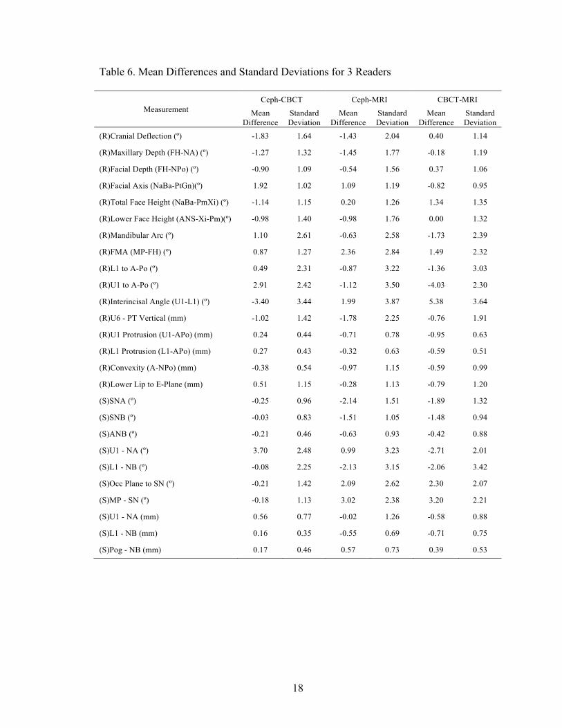
Figure 4. Facial Axis - 3 Readers

24
Lateral Ceph - CBCT
Lateral Ceph - MRI
CBCT-MRI
Figure 5. Total Face Height - 3 Readers

25
Lateral Ceph - CBCT
Lateral Ceph - MRI
CBCT-MRI
Figure 6. Lower Face Height - 3 Readers

26
Lateral Ceph - CBCT
Lateral Ceph - MRI
CBCT-MRI
Figure 7. Mandibular Arc - 3 Readers
27
Lateral Ceph - CBCT
Lateral Ceph - MRI
CBCT-MRI
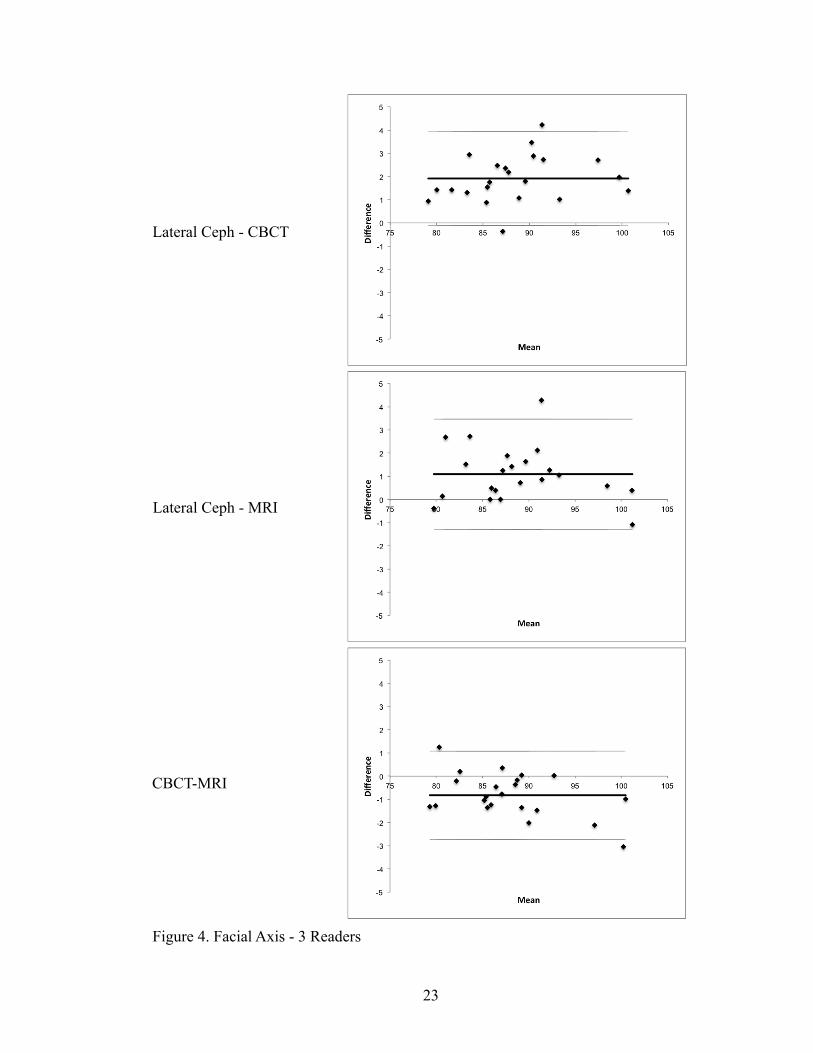
Figure 8. Mandibular Plane Angle - 3 Readers
28
Lateral Ceph - CBCT
Lateral Ceph - MRI
CBCT-MRI
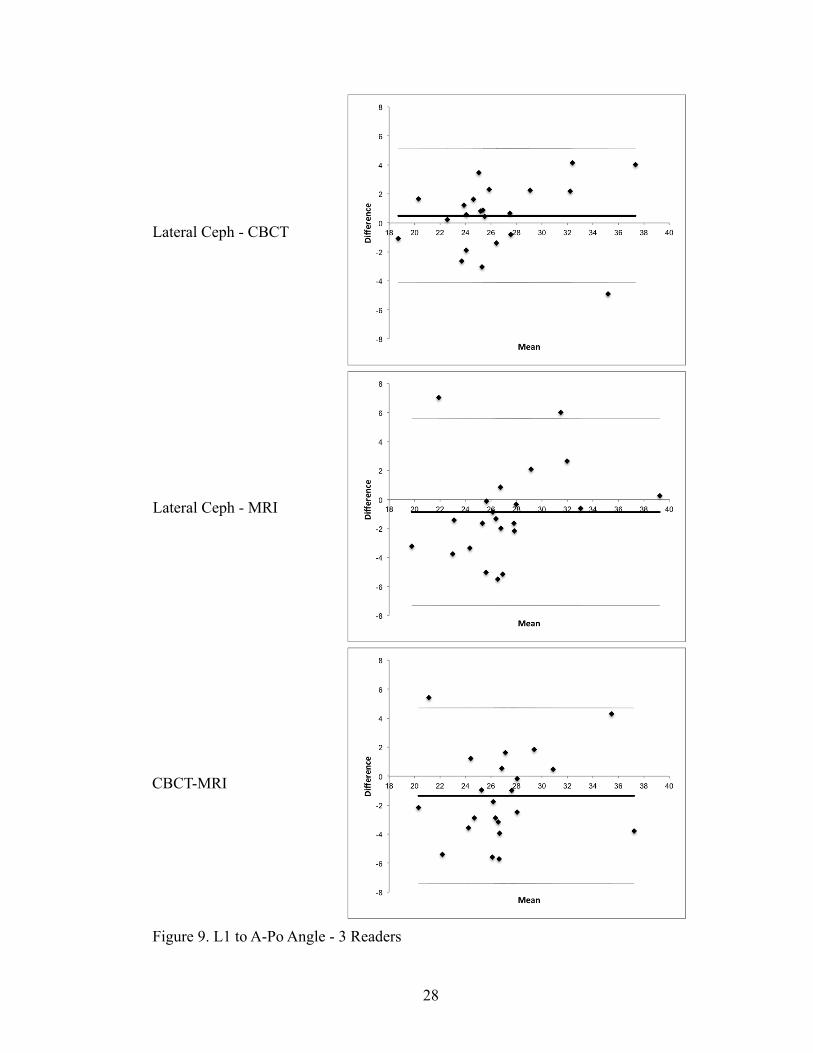
Figure 9. L1 to A-Po Angle - 3 Readers

29
Lateral Ceph - CBCT
Lateral Ceph - MRI
CBCT-MRI
Figure 10. U1 to A-Po Angle - 3 Readers

30
Lateral Ceph - CBCT
Lateral Ceph - MRI
CBCT-MRI
Figure 11. Interincisal Angle - 3 Readers

31
Lateral Ceph - CBCT
Lateral Ceph - MRI
CBCT-MRI
Figure 12. U6 to PtV - 3 Readers

32
Lateral Ceph - CBCT
Lateral Ceph - MRI
CBCT-MRI
Figure 13. U1 Protrusion - 3 Readers
33
Lateral Ceph - CBCT
Lateral Ceph - MRI
CBCT-MRI
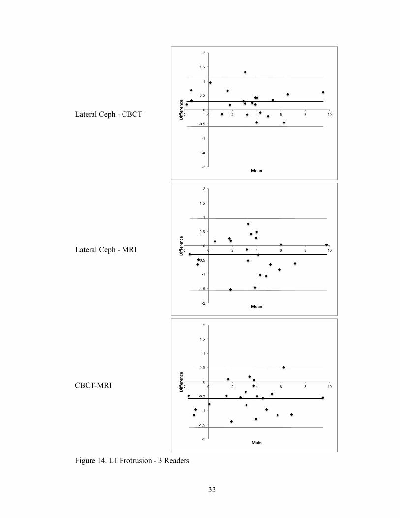
Figure 14. L1 Protrusion - 3 Readers

34
Lateral Ceph - CBCT
Lateral Ceph - MRI
CBCT-MRI
Figure 15. Convexity - 3 Readers

35
Lateral Ceph - CBCT
Lateral Ceph - MRI
CBCT-MRI
Figure 16. Lower Lip to E-Plane - 3 Readers
36
Lateral Ceph - CBCT
Lateral Ceph - MRI
CBCT-MRI
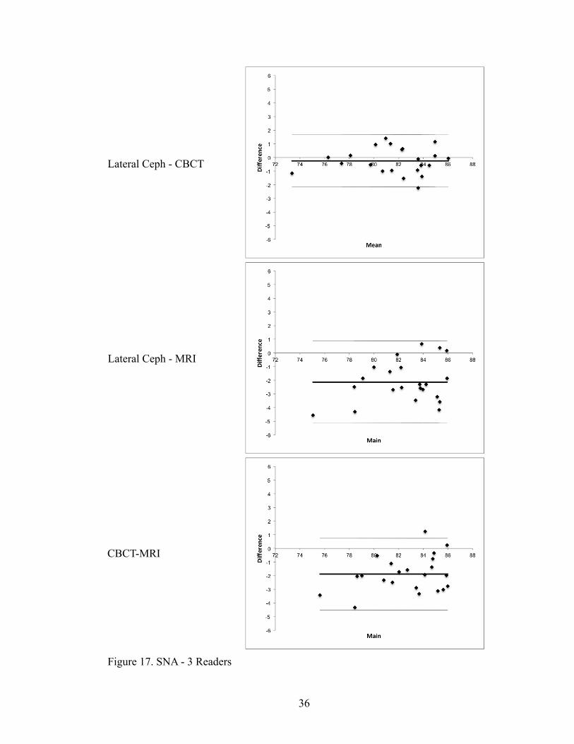
Figure 17. SNA - 3 Readers

37
Lateral Ceph - CBCT
Lateral Ceph - MRI
CBCT-MRI
Figure 18. SNB - 3 Readers

38
Lateral Ceph - CBCT
Lateral Ceph - MRI
CBCT-MRI
Figure 19. ANB - 3 Readers

39
Lateral Ceph - CBCT
Lateral Ceph - MRI
CBCT-MRI
Figure 20. U1-NA Angle - 3 Readers

40
Lateral Ceph - CBCT
Lateral Ceph - MRI
CBCT-MRI
Figure 21. L1-NB Angle - 3 Readers
41
Lateral Ceph - CBCT
Lateral Ceph - MRI
CBCT-MRI
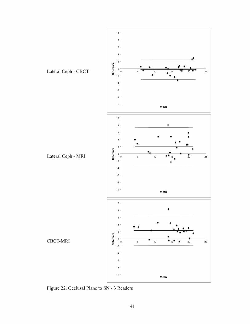
Figure 22. Occlusal Plane to SN - 3 Readers

42
Lateral Ceph - CBCT
Lateral Ceph - MRI
CBCT-MRI
Figure 23. SN-MP - 3 Readers

43
Lateral Ceph - CBCT
Lateral Ceph - MRI
CBCT-MRI
Figure 24. U1-NA Distance - 3 Readers

44
Lateral Ceph - CBCT
Lateral Ceph - MRI
CBCT-MRI
Figure 25. L1-NB Distance - 3 Readers

45
Lateral Ceph - CBCT
Lateral Ceph - MRI
CBCT-MRI
Figure 26. Pog-NB - 3 Readers

46
Lateral Ceph - CBCT
Lateral Ceph - MRI
CBCT-MRI
Figure 27. Cranial Deflection - 2 Readers

47
Lateral Ceph - CBCT
Lateral Ceph - MRI
CBCT-MRI
Figure 28. Maxillary Depth - 2 Readers

48
Lateral Ceph - CBCT
Lateral Ceph - MRI
CBCT-MRI
Figure 29. Facial Depth - 2 Readers

49
Lateral Ceph - CBCT
Lateral Ceph - MRI
CBCT-MRI
Figure 30. Facial Axis - 2 Readers

50
Lateral Ceph - CBCT
Lateral Ceph - MRI
CBCT-MRI
Figure 31. Total Face Height - 2 Readers
51
Lateral Ceph - CBCT
Lateral Ceph - MRI
CBCT-MRI
Figure 32. Lower Face Height - 2 Readers

52
Lateral Ceph - CBCT
Lateral Ceph - MRI
CBCT-MRI
Figure 33. Mandibular Arc - 2 Readers

53
Lateral Ceph - CBCT
Lateral Ceph - MRI
CBCT-MRI
Figure 34. Mandibular Plane Angle - 2 Readers
54
Lateral Ceph - CBCT
Lateral Ceph - MRI
CBCT-MRI
Figure 35. L1 to A-Po Angle - 2 Readers
55
Lateral Ceph - CBCT
Lateral Ceph - MRI
CBCT-MRI
Figure 36. U1 to A-Po Angle - 2 Readers

56
Lateral Ceph - CBCT
Lateral Ceph - MRI
CBCT-MRI
Figure 37. Interincisal Angle - 2 Readers

57
Lateral Ceph - CBCT
Lateral Ceph - MRI
CBCT-MRI
Figure 38. U6 to PtV - 2 Readers

58
Lateral Ceph - CBCT
Lateral Ceph - MRI
CBCT-MRI
Figure 39. U1 Protrusion - 2 Readers
59
Lateral Ceph - CBCT
Lateral Ceph - MRI
CBCT-MRI
Figure 40. L1 Protrusion - 2 Readers

60
Lateral Ceph - CBCT
Lateral Ceph - MRI
CBCT-MRI
Figure 41. Convexity - 2 Readers
61
Lateral Ceph - CBCT
Lateral Ceph - MRI
CBCT-MRI
Figure 42. Lower Lip to E-Plane - 2 Readers

62
Lateral Ceph - CBCT
Lateral Ceph - MRI
CBCT-MRI
Figure 43. SNA - 2 Readers
63
Lateral Ceph - CBCT
Lateral Ceph - MRI
CBCT-MRI
Figure 44. SNB - 2 Readers

64
Lateral Ceph - CBCT
Lateral Ceph - MRI
CBCT-MRI
Figure 45. ANB - 2 Readers

65
Lateral Ceph - CBCT
Lateral Ceph - MRI
CBCT-MRI
Figure 46. U1-NA Angle - 2 Readers

66
Lateral Ceph - CBCT
Lateral Ceph - MRI
CBCT-MRI
Figure 47. L1-NB Angle - 2 Readers

67
Lateral Ceph - CBCT
Lateral Ceph - MRI
CBCT-MRI
Figure 48. Occlusal Plane to SN - 2 Readers

68
Lateral Ceph - CBCT
Lateral Ceph - MRI
CBCT-MRI
Figure 49. SN-MP - 2 Readers

69
Lateral Ceph - CBCT
Lateral Ceph - MRI
CBCT-MRI
Figure 50. U1-NA Distance - 2 Readers

70
Lateral Ceph - CBCT
Lateral Ceph - MRI
CBCT-MRI
Figure 51. L1-NB Distance - 2 Readers

71
Lateral Ceph - CBCT
Lateral Ceph - MRI
CBCT-MRI
Figure 52. Pog-NB - 2 Readers

72
Table 8. Degree of Agreement – 3 Readers
Measurement Clinical Norm
Clinical Deviation
Range
Ceph-MRI Mean
CBCT-MRI Mean
Average Deviation
Deviation as
Percentage Clinical
Deviation Range
Degree of Agreement
(R)Facial Depth (FH-NPo) (º) 87.8 ± 3.0 6.0 -0.54 0.37 -0.08 1.4%
Very Good
(0-10%)
(R)Facial Axis (NaBa-PtGn)(º) 90 ± 3.5 7.0 1.09 -0.82 0.13 1.9%
(S)U1 - NA (mm) 4.3 ± 2.7 5.4 -0.02 -0.58 -0.30 5.5%
(R)Lower Face Height (ANS-Xi-Pm)(º) 45.0 ± 4.0 8.0 -0.98 0.00 -0.49 6.1%
(S)U1 - NA (º) 22.8 ± 5.7 11.4 0.99 -2.71 -0.86 7.5%
(R)Cranial Deflection (º) 27.3 ± 3.0 6.0 -1.43 0.40 -0.51 8.5%
(R)L1 Protrusion (L1-APo) (mm) 1.0 ± 2.3 4.6 -0.32 -0.59 -0.45 9.8%
(R)Total Face Height (NaBa-Pm-Xi)(º) 60.0 ± 3.0 6.0 0.20 1.34 0.77 12.8%
Good (10-20%)
(R)Lower Lip to E-Plane (mm) -2.0 ± 2.0 4.0 -0.28 -0.79 -0.53 13.3%
(R)Maxillary Depth (FH-NA) (º) 90.0 ± 3.0 6.0 -1.45 -0.18 -0.81 13.6%
(R)L1 to A-Po (º) 22.0 ± 4.0 8.0 -0.87 -1.36 -1.12 13.9%
(S)Pog - NB (mm) 1.9 ± 1.7 3.4 0.57 0.39 0.48 14.1%
(R)Mandibular Arc (º) 29.0 ± 4.0 8.0 -0.63 -1.73 -1.18 14.7%
(S)ANB (º) 1.6 ± 1.5 3.0 -0.63 -0.42 -0.52 17.3%
(S)L1 - NB (º) 25.3 ± 6.0 12.0 -2.13 -2.06 -2.10 17.5%
(S)L1 - NB (mm) 4.0 ± 1.8 3.6 -0.55 -0.71 -0.63 17.5%
(R)U-Incisor Protrusion (U1-APo) (mm) 3.5 ± 2.3 4.6 -0.71 -0.95 -0.83 18.0%
(R)Convexity (A-NPo) (mm) 1.2 ± 2.0 4.0 -0.97 -0.59 -0.78 19.5%
(R)U6 - PT Vertical (mm) 15.5 ± 3.0 6.0 -1.78 -0.76 -1.27 21.1%
Minor Bias
(20-30%)
(R)FMA (MP-FH) (º) 24.7 ± 4.5 9.0 2.36 1.49 1.93 21.4%
(S)SNB (º) 80.9 ± 3.4 6.8 -1.51 -1.48 -1.50 22.0%
(S)MP - SN (º) 33.0 ± 6.0 12.0 3.02 3.20 3.11 25.9%
(S)SNA (º) 82.0 ± 3.5 7.0 -2.14 -1.89 -2.01 28.7%
(R)Interincisal Angle (U1-L1) (º) 130.0 ± 6.0 12.0 1.99 5.38 3.68 30.7%
Significant Bias
(>30%) (R)U-Incisor Inclination (U1-APo) (º) 28.0 ± 4.0 8.0 -1.12 -4.03 -2.57 32.2%
(S)Occ Plane to SN (º) 14.4 ± 2.5 5.0 2.09 2.30 2.20 43.9%

73
Table 9. Degree of Agreement – 2 Readers
Measurement Clinical Norm
Clinical Deviation
Range
Ceph-MRI Mean
CBCT-MRI Mean
Average Deviation
Deviation as
Percentage Clinical
Deviation Range
Degree of Agreement
(S)U1 - NA (mm) 4.3 ± 2.7 5.4 0.19 -0.21 -0.01 0.1%
Very Good
(0-10%)
(R)Lower Face Height (ANS-Xi-Pm)(º) 45.0 ± 4.0 8.0 -0.47 0.58 0.06 0.7%
(R)Facial Axis (NaBa-PtGn)(º) 90 ± 3.5 7.0 0.91 -0.80 0.06 0.8%
(R)L1 Protrusion (L1-APo) (mm) 1.0 ± 2.3 4.6 -0.09 -0.33 -0.21 4.5%
(S)U1 - NA (º) 22.8 ± 5.7 11.4 0.89 -2.11 -0.61 5.3%
(R)Facial Depth (FH-NPo) (º) 87.8 ± 3.0 6.0 -0.77 0.04 -0.37 6.1%
(R)Cranial Deflection (º) 27.3 ± 3.0 6.0 -1.33 0.27 -0.53 8.8%
(R)L1 to A-Po (º) 22.0 ± 4.0 8.0 -0.83 -1.13 -0.98 12.2%
Good (10-20%)
(S)L1 - NB (mm) 4.0 ± 1.8 3.6 -0.33 -0.56 -0.45 12.4% (R)U-Incisor Protrusion (U1-APo) (mm) 3.5 ± 2.3 4.6 -0.56 -0.72 -0.64 13.8%
(R)Lower Lip to E-Plane (mm) -2.0 ± 2.0 4.0 -0.27 -0.93 -0.60 15.0%
(R)Total Face Height (NaBa-Pm-Xi)(º) 60.0 ± 3.0 6.0 0.24 1.59 0.91 15.2%
(R)Mandibular Arc (º) 29.0 ± 4.0 8.0 -0.67 -1.85 -1.26 15.8%
(S)Pog - NB (mm) 1.9 ± 1.7 3.4 0.65 0.43 0.54 15.9%
(R)U6 - PT Vertical (mm) 15.5 ± 3.0 6.0 -1.58 -0.67 -1.12 18.7%
(S)L1 - NB (º) 25.3 ± 6.0 12.0 -2.38 -2.16 -2.27 18.9%
(S)ANB (º) 1.6 ± 1.5 3.0 -0.65 -0.60 -0.62 20.8%
Minor Bias
(20-30%)
(R)Maxillary Depth (FH-NA) (º) 90.0 ± 3.0 6.0 -1.80 -0.74 -1.27 21.1%
(S)SNB (º) 80.9 ± 3.4 6.8 -1.59 -1.55 -1.57 23.1%
(R)Convexity (A-NPo) (mm) 1.2 ± 2.0 4.0 -1.09 -0.83 -0.96 24.1%
(S)Occ Plane to SN (º) 14.4 ± 2.5 5.0 0.97 1.46 1.21 24.3%
(R)FMA (MP-FH) (º) 24.7 ± 4.5 9.0 2.92 1.91 2.41 26.8%
(S)MP - SN (º) 33.0 ± 6.0 12.0 3.36 3.36 3.36 28.0%
(R)Interincisal Angle (U1-L1) (º) 130.0 ± 6.0 12.0 2.11 4.81 3.46 28.8%
(R)U-Incisor Inclination (U1-APo) (º) 28.0 ± 4.0 8.0 -1.28 -3.69 -2.49 31.1% Significant
Bias (>30%) (S)SNA (º) 82.0 ± 3.5 7.0 -2.24 -2.15 -2.19 31.3%

74
Table 10. Comparing Mean Differences for 2 and 3 Readers
Measurement Ceph-CBCT Ceph-MRI CBCT-MRI
3 Readers 2 Readers 3 Readers 2 Readers 3 Readers 2 Readers
(R)Cranial Deflection (º) -1.83 -1.60 -1.43 -1.33 0.40 0.27
(R)Maxillary Depth (FH-NA) (º) -1.27 -1.06 -1.45 -1.80 -0.18 -0.74
(R)Facial Depth (FH-NPo) (º) -0.90 -0.81 -0.54 -0.77 0.37 0.04
(R)Facial Axis (NaBa-PtGn)(º) 1.92 1.71 1.09 0.91 -0.82 -0.80
(R)Total Face Height (NaBa-PmXi) (º) -1.14 -1.35 0.20 0.24 1.34 1.59
(R)Lower Face Height (ANS-Xi-Pm)(º) -0.98 -1.05 -0.98 -0.47 0.00 0.58
(R)Mandibular Arc (º) 1.10 1.18 -0.63 -0.67 -1.73 -1.85
(R)FMA (MP-FH) (º) 0.87 1.01 2.36 2.92 1.49 1.91
(R)L1 to A-Po (º) 0.49 0.30 -0.87 -0.83 -1.36 -1.13
(R)U1 to A-Po (º) 2.91 2.41 -1.12 -1.28 -4.03 -3.69
(R)Interincisal Angle (U1-L1) (º) -3.40 -2.70 1.99 2.11 5.38 4.81
(R)U6 - PT Vertical (mm) -1.02 -0.90 -1.78 -1.58 -0.76 -0.67
(R)U1 Protrusion (U1-APo) (mm) 0.24 0.16 -0.71 -0.56 -0.95 -0.72
(R)L1 Protrusion (L1-APo) (mm) 0.27 0.24 -0.32 -0.09 -0.59 -0.33
(R)Convexity (A-NPo) (mm) -0.38 -0.26 -0.97 -1.09 -0.59 -0.83
(R)Lower Lip to E-Plane (mm) 0.51 0.65 -0.28 -0.27 -0.79 -0.93
(S)SNA (º) -0.25 -0.09 -2.14 -2.24 -1.89 -2.15
(S)SNB (º) -0.03 -0.04 -1.51 -1.59 -1.48 -1.55
(S)ANB (º) -0.21 -0.05 -0.63 -0.65 -0.42 -0.60
(S)U1 - NA (º) 3.70 3.00 0.99 0.89 -2.71 -2.11
(S)L1 - NB (º) -0.08 -0.22 -2.13 -2.38 -2.06 -2.16
(S)Occ Plane to SN (º) -0.21 -0.49 2.09 0.97 2.30 1.46
(S)MP - SN (º) -0.18 0.00 3.02 3.36 3.20 3.36
(S)U1 - NA (mm) 0.56 0.40 -0.02 0.19 -0.58 -0.21
(S)L1 - NB (mm) 0.16 0.24 -0.55 -0.33 -0.71 -0.56
(S)Pog - NB (mm) 0.17 0.22 0.57 0.65 0.39 0.43

75
Table 11. Comparing Standard Deviations for 2 and 3 Readers
Measurement Ceph-CBCT Ceph-MRI CBCT-MRI
3 Readers 2 Readers 3 Readers 2 Readers 3 Readers 2 Readers
(R)Cranial Deflection (º) 1.64 1.78 2.04 2.08 1.14 1.16
(R)Maxillary Depth (FH-NA) (º) 1.32 1.40 1.77 2.13 1.19 1.30
(R)Facial Depth (FH-NPo) (º) 1.09 1.31 1.56 1.84 1.06 1.22
(R)Facial Axis (NaBa-PtGn)(º) 1.02 1.05 1.19 1.33 0.95 0.88
(R)Total Face Height (NaBa-PmXi) (º) 1.15 1.19 1.26 1.54 1.35 1.19
(R)Lower Face Height (ANS-Xi-Pm)(º) 1.40 1.16 1.76 1.75 1.32 1.18
(R)Mandibular Arc (º) 2.61 2.85 2.58 2.92 2.39 2.29
(R)FMA (MP-FH) (º) 1.27 1.45 2.84 2.40 2.32 1.75
(R)L1 to A-Po (º) 2.31 2.44 3.22 3.38 3.03 2.67
(R)U1 to A-Po (º) 2.42 2.42 3.50 3.28 2.30 2.62
(R)Interincisal Angle (U1-L1) (º) 3.44 3.31 3.87 4.11 3.64 3.96
(R)U6 - PT Vertical (mm) 1.42 1.55 2.25 2.36 1.91 1.76
(R)U1 Protrusion (U1-APo) (mm) 0.44 0.46 0.78 0.87 0.63 0.61
(R)L1 Protrusion (L1-APo) (mm) 0.43 0.44 0.63 0.76 0.51 0.66
(R)Convexity (A-NPo) (mm) 0.54 0.49 1.15 1.25 0.99 1.02
(R)Lower Lip to E-Plane (mm) 1.15 0.68 1.13 1.12 1.20 0.93
(S)SNA (º) 0.96 0.91 1.51 1.59 1.32 1.48
(S)SNB (º) 0.83 0.82 1.05 1.10 0.94 0.95
(S)ANB (º) 0.46 0.38 0.93 1.03 0.88 0.93
(S)U1 - NA (º) 2.48 2.17 3.23 2.67 2.01 2.04
(S)L1 - NB (º) 2.25 2.56 3.15 3.49 3.42 3.38
(S)Occ Plane to SN (º) 1.42 1.48 2.62 2.64 2.07 1.99
(S)MP - SN (º) 1.13 1.18 2.38 1.93 2.21 1.23
(S)U1 - NA (mm) 0.77 0.77 1.26 1.25 0.88 0.74
(S)L1 - NB (mm) 0.35 0.32 0.69 0.87 0.75 0.89
(S)Pog - NB (mm) 0.46 0.60 0.73 0.84 0.53 0.56

76
CHAPTER FIVE
DISCUSSION
Analysis of Measures with Good Agreement or Minor Bias
A further examination of the Bland-Altman plots for each measurement reveals
trends in error. The plots for cranial deflection, maxillary depth and facial depth show a
bias where the cephalometric values obtained from the lateral cephs are less than that
obtained from the CBCTs and MRIs. This would suggest that when the lateral cephs are
traced, either Frankfort Horizontal is relatively the same and the NaBa plane, NA plane
and NPog plane show a more clockwise position as shown in Figure 53, or that Frankfort
Horizontal has a more counter-clockwise position as in Figure 54. Examining the plots
for MPA shows that the values obtained when tracing lateral cephs are greater than that
when tracing CBCTs or MRIs. This would also be indicative of a counter-clockwise
rotation of Frankfort Horizontal.
The two points comprising Frankfort Horizontal are porion and orbitale. It was
earlier identified in the methods and materials section that location of porion in a 3D
volume was only possible by scrolling through the sagittal slices and selecting the most
superior point along the roof of the bony external meatus. It is possible that this selected
point is lower than the one selected when tracing a 2 dimensional ceph, thus creating a
counter-clockwise rotation of Frankfort-Horizontal. The other possibility is that when
scrolling to select orbitale the point chosen is too high.

77
Figure 53. Frankfort-Horizontal Plane Constant
Figure 54. Frankfort-Horizontal Plane with Counter-Clockwise Rotation

78
An inspection of SNA and SNB reveals that the values obtained by tracing lateral
cephs and CBCTs are similar, with the MRI values showing a bias to be greater than
both. ANB shows good agreement among all 3 modalities. This would indicate either that
the MRI landmarks for A and B point are both more anteriorly positioned as shown in
Figure 55, or that the SN plane has a clockwise bias when tracing MRIs as shown in
Figure 56. When comparing the Bland-Altman plots for occlusal plane angle and Steiner
mandibular plane angle (GoGn-SN), the cephalometric values obtained from MRIs show
a bias towards being lesser than both lateral cephs and CBCTs. This would be in
agreement with a more clockwise SN plane when tracing MRIs.
When comparing the Ricketts analysis angular measurements for L1-APo, it is
apparent that tracing the MRIs gives the largest angular measurement and tracing CBCTs
the smallest measurement. Doing the same with U1-APo, MRI again gives the largest
measurement and CBCT the smallest. This indicates that compared to a lateral ceph, the
upper and lower incisors appear more flared when tracing an MRI and more upright when
tracing a CBCT. This trend is shown in Figure 57. This helps to account for some of the
other minor biases seen in other measurements, such as U1P, L1P, U1/NA and L1/NB,
U1-NA and L1-NB.
Analysis of Measures with Significant Bias
There are several measurements that show a larger amount of bias. However,
upon closer examination they could be due to the sum of a couple of the smaller biases.
The largest bias was seen in the interincisal angle measurement. The plots reveal that the
largest interincisal angle values come from CBCT, and the smallest from MRI. This is in

79
Figure 55. SN Plane Constant
Figure 56. SN Plane with Clockwise Rotation

80
Figure 57. Trends when Tracing Incisors
agreement with the earlier discussed minor biases of CBCT tracings indicating more
upright incisors and MRI tracings showing more flared incisors. Compounding these two
minor biases could account for the larger bias seen in interincisal angle measurements.
Comparing the Results from 3 Readers and 2 Readers
There were no significant differences noted when comparing the results between
3 readers and 2 readers. There were a few values that showed mildly better correlation
when comparing mean difference, such as Steiner’s U1-NA angle and occlusal plane to
SN angle. However, there were also measurements that showed mildly worse correlation,
such as Ricketts maxillary depth and FMA. When considering standard deviation, there
were also cases of slightly better correlation (SN-MP, FMA) and slightly worse
correlation (maxillary depth, facial depth). Overall, the trends of error were unchanged.
Legend
Red CBCT
Green Ceph
Blue MRI

81
Cephalometric Error
A discrepancy between cephalometric values obtained when comparing different
imaging modalities is not uncommon. Previous studies have shown statistically
significant differences when comparing manually traced radiographs to digitally scanned
and digitized images,23,24 as well as between lateral cephs and 3D CBCT scans.25
However, these studies have concluded that the differences were not clinically
significant.
Another earlier study examining magnification in common digital lateral
cephalometric machines showed 8.1% to 13.2% vertical magnification and 8.2% to
14.2% horizontal magnification. One machine in the study also displayed non-symmetric
magnification characteristics. However, the study concluded that for clinical purposes all
the machines evaluated in the study were adequate.26
The largest average error when comparing tracing lateral cephs to either CBCT or
MRI in this study occurred when comparing interincisal measurements. The Bland-
Altman plot for comparing lateral cephs to CBCTs for interincisal angle showed a bias of
-3.39°. Compared to the clinical norm for Ricketts analysis for Caucasian patients (from
Dolphin Imaging, 2013) of 130.0° ± 6.0°, this error is well within the roughly 8% to 14%
error seen noted in common lateral cephalometric machines. It is also only about half the
magnitude of the corresponding standard deviation.
Evaluation of Clinical Viability
This study suggests a good to very good agreement for almost half of the
measurements evaluated. The rest appear to show a small to moderate degree of bias, but

82
the biases appear to be well within the limits of clinical acceptability. They also appear
directional in most cases and can be adjusted for.
The larger issues at this time appear to be other limitations of practical MRI use
for orthodontic diagnosis. The current cost of having an MRI taken both prior to and post
orthodontic treatment is prohibitive in many cases. It would also likely not be covered by
insurance at the time of this study. There would be difficulty in having young patients
stay still for the duration of time required for an MRI to be taken. MRI is also not
applicable for progress examinations during orthodontic treatment due to the presence of
metal in most orthodontic appliances. However, some of the non-conventional modalities
of treatment such as the use of clear aligners would allow for this. A previous study also
noted that titanium brackets and some specific types of stainless steel brackets had no
effect on MRI.20 Lastly, most orthodontists are not familiar with reading MRIs and would
need training in order to be able to trace MR scans.
If MRI is the chosen imaging modality of the treating orthodontist and the patient,
this study suggests that with relatively quick training and the relevant software an
orthodontist would be able to obtain clinically adequate cephalometric data from an MRI
image.
Suggestions for Improvement
To improve the agreement between the imaging modalities, one suggestion would
be to have each reader reorient the 3D volumes on their own. In a clinical practice setting,
this would likely be the first action by an orthodontist tracing a 3D volume. In this study,
the decision was made after the pilot experiment to leave the head orientations as is.

83
However, in retrospect the agreement may have been better if the images had been
reoriented prior to landmark identification.
Another possible improvement would be to have a radiologist familiar with
evaluating MR scans aid with calibration of the readers. There was some degree of debate
during calibration as to the correct location of certain landmarks, and a radiologist with
more experience dealing with such images would have aided in more correct and
consistent landmark identification.

84
CHAPTER SIX
CONCLUSIONS
Conclusions
1. There are statistically significant differences in certain Ricketts and Steiner analysis
cephalometric measurements when comparing data obtained from digital lateral
cephalograms, cone beam computed tomography scans, and magnetic resonance
imaging scans.
2. The differences in cephalometric measurements are within the limits of clinical
variability and are adequate for clinical evaluation of a patient.
3. Under the conditions of this study, tracing magnetic resonance imaging scans can yield
similar orthodontic cephalometric values to conventional lateral cephalograms
and cone beam computed tomography scans.

85
REFERENCES
1. Parkin DM, Darby SC. Cancers in 2010 attributable to ionising radiation exposure in
the UK. Br J Cancer 2011;105:S57-S65.
2. Silva MAG, Wolf U, Heinicke F, Bumann A, Visser H, Hirsch E. Cone-beam computed tomography for routine orthodontic treatment planning: A radiation dose evaluation. Am J Orthod Dentofacial Orthop 2008;133:640.e1-640.e5.
3. Cattaneo PM, Bloch CB, Calmar D, Hjortshoj M, Melsen B. Comparison between conventional and cone-beam computed tomography–generated cephalograms. Am J Orthod Dentofacial Orthop 2008;134:798-802.
4. Ludlow JB, Gubler M, Cevidanes L, Mol A. Precision of cephalometric landmark identification: cone-beam computed tomography vs conventional cephalometric views. Am J Orthod Dentofacial Orthop 2009;136(3):312.
5. Gribel BF, Gribel MN, Frazäo DC, McNamara JA Jr, Manzi FR. Accuracy and reliability of craniometric measurements on lateral cephalometry and 3D measurements on CBCT scans. Angle Orthod 2011;81(1):26-35.
6. Suman S, Maniar M, Fornace AJ Jr, Datta K. Administration of ON 01210.Na after exposure to ionizing radiation protects bone marrow cells by attenuating DNA damage response. Radiat Oncol 2012;7:6.
7. De la Cal C, Fernández-Solari J, Mohn C, Prestifilippo J, Pugnaloni A, Medina V, Elverdin J. Radiation produces irreversible chronic dysfunction in the submandibular glands of the rat. Open Dent J 2012;6:8-13.
8. Williams PM, Fletcher S. Health effects of prenatal radiation exposure. Am Fam Physician 2010;82(5):488-93.
9. Rathnayaka K, Momot KI, Noser H, Volp A, Schuetz MA, Sahama T, Schmutz B. Quantification of the accuracy of MRI generated 3D models of long bones compared to CT generated 3D models. Med Eng Phys 2011;doi:10.1016/j.medengphy.2011.07.027.
10. Maizlin ZV, Nutiu N, Dent PB, Vos PM, Fenton DM, Kirby JM, Vora P, Gillies JH, Clement JJ. Displacement of the temporomandibular joint disk: correlation between clinical findings and MRI characteristics. J Can Dent Assoc 2010;76:a3.

86
11. Pirilä-Parkkinen K, Löppönen H, Nieminen P, Tolonen U, Paakko E, Pirttiniemi P. Validity of upper airway assessment in children: a clinical, cephalometric, and MRI study. Angle Orthod. 2011;81(3):433-9.
12. Plooij JM, Maal TJJ, Haers P, Borstlap WA, Kuijpers-Jagtman AM, Berge SJ. Digital three-dimensional image fusion processes for planning and evaluating orthodontics and orthognathic surgery. A systematic review. Int J Oral Maxillofac Surg 2011;40(4):341-52.
13. Terajima M, Yanagita N, Ozeki K, Hoshino Y, Mori N, Goto TK, Tokumori K, Aoki Y, Nakasima A. Three-dimensional analysis system for orthognathic surgery patients with jaw deformities. Am J Orthod Dentofacial Orthop 2008;134:100-11.
14. Ferretti F, Malventi M, Malasoma R. Dental magnetic resonance imaging: study of impacted mandibular third molars. Dentomaxillofac Radiol 2009;38(6):387-92.
15. Idiyatullin D, Corum C, Moeller S, Prasad HS, Garwood M, Mixdorf DR. Dental magnetic resonance imaging: making the invisible visible. J Endod 2011;37(6):745-52.
16. van Haute FRB, Taboada GF, Correa LL, Lima GAB, Fontes R, Riello AP, Dominici M, Gadelha MR. Prevalence of sleep apnea and metabolic abnormalities in patients with acromegaly and analysis of cephalometric parameters by magnetic resonance imaging. Eur J Endocrinol 2008;158(4):459-65.
17. Elison JM, Leggitt VL, Thomson M, Oyoyo U, Wycliffe ND. Influence of common orthodontic appliances on the diagnostic quality of cranial magnetic resonance images. Am J Orthod Dentofacial Orthop 2008;134(4):563-72.
18. Yilmaz S, Misirlioglu M. The effect of 3 T MRI on microleakage of amalgam restorations. Dentomaxillofac Radiol 2013;42:20130072
19. Hutton J, Walker LG, Gilbert FJ, Evans DG, Eeles R, Kwan-Lim GE, Thompson D, Pointon LJ, Sharp DM, Leach MO. Psychological impact and acceptability of magnetic resonance imaging and X-ray mammography: the MARIBS Study. Br J Cancer 2011;104(4):578-86.
20. McIsaac HK, Thordarson DS, Shafran R, Rachman S, Poole G. Claustrophobia and the magnetic resonance imaging procedure. J Behav Med 1998;21(3):255-68.
21. Williams WA. Cephalometric Analysis Using Magnetic Resonance Imaging: Unpublished Masters Thesis, Loma Linda University Graduate School, Department of Orthodontics 2008.
22. Sanders MA. Facial Type Analysis Comparison Between MRI, CBCT, and Lateral Cephalometrics: Unpublished Masters Thesis, Loma Linda University Graduate School, Department of Orthodontics 2010.

87
23. AlBarakati SF, Kula KS, Ghoneima AA. The reliability and reproducibility of cephalometric measurements: a comparison of conventional and digital methods. Dentomaxillofac Radiol 2012;41:11-17.
24. Naoumova J, Lindman R. A comparison of manual traced images and corresponding scanned radiographs digitally traced. Eur J Orthod 2009;31:247-253. Dentomaxillofac Radiol 2010;39:100-106.
25. Nalcaci R, Ozturk F, Sokucu O. A comparison of two-dimensional radiography and three-dimensional computed tomography in angular cephalometric measurements.
26. Schnepper GM. Magnification in Images Produced by Five Popular Digital Lateral Cephalometric Machines: Unpublished Masters Thesis, Loma Linda University Graduate School, Department of Orthodontics 2005.

88
APP
END
IX A
: Raw
Dat
a
Pt/R
eade
r M
easu
rem
ent
R1_
Cep
h R
1_C
BC
T R
1_M
RI
R2_
Cep
h R
2_C
BC
T R
2_M
RI
R3_
Cep
h R
3_C
BC
T R
3_M
RI
Pt1
(R)C
rani
al D
efle
ctio
n (º)
25
.9
26.1
26
.25
23.9
26
.15
26.0
5 26
.4
26
26.3
(R)M
axill
ary
Dep
th (F
H-N
A) (
º) 91
.9
91.4
87
.25
91.4
92
.1
90.8
91
.2
90.9
91
.2
(R
)Fac
ial D
epth
(FH
-NPo
) (º)
95.3
95
92
.85
95.4
95
.9
95.6
95
.8
94.8
94
.1
(R
)Fac
ial A
xis-
Ric
ketts
(NaB
a-Pt
Gn)
(º)
100
99.7
99
.75
103
100.
8 10
2.35
10
1.1
99.4
5 10
0.8
(R
)Tot
al F
ace
Hei
ght (
NaB
a-Pm
Xi)
(º)
44.3
46
.15
43.8
5 42
.9
45.6
5 42
.55
44.5
46
.3
45.9
(R)L
ower
Fac
e H
eigh
t (A
NS-
Xi-P
m)(
º) 35
.6
37.3
37
.1
36.6
36
.9
38.6
5 35
.7
37.0
5 38
.95
(R
)Man
dibu
lar A
rc (º
) 45
.9
41.7
5 46
43
.9
40.5
5 44
.85
43.7
42
.65
45.1
5
(R)F
MA
(MP-
FH) (
º) 12
.8
12.8
8.
75
11.1
12
.95
10.1
13
.5
13.5
10
.25
(R
)L1
to A
-Po
(º)
17.3
18
.85
22.9
24
.1
19.7
5 29
.15
22
19.8
5 22
.6
(R
)U1
to A
-Po
(º)
20.4
12
.1
16.7
5 18
.3
9.7
12.8
15
.2
11
12.2
5
(R)I
nter
inci
sal A
ngle
(U1-
L1) (
º) 14
2.3
149.
05
140.
25
137.
6 15
0.5
138.
05
142.
8 14
9.15
14
5.2
(R
)U6
- PT
Ver
tical
(mm
) 24
.2
23.4
5 24
.3
24.1
24
.45
28.4
23
.1
23.3
25
.95
(R
)U1
Prot
rusi
on (U
1-A
Po) (
mm
) 0.
6 0.
4 0.
65
0.4
0.4
1.4
0.7
0.55
1.
5
(R)L
1 Pr
otru
sion
(L1-
APo
) (m
m)
-2.4
-2
.15
-2.7
-1
.1
-1.7
-0
.7
-1.5
-1
.7
-0.7
(R)C
onve
xity
(A-N
Po) (
mm
) -3
.4
-3.5
-5
-3
.9
-3.6
5 -4
.55
-4.5
-3
.9
-2.8
5
(R)L
ower
Lip
to E
-Pla
ne (m
m)
-9.5
-9
.2
-9.4
5 -8
.3
-9
-10
-9.7
-9
.65
-9.1
5
(S)S
NA
(º)
86.2
86
.1
83.7
5 86
.7
86.3
86
.8
85.1
85
.8
86.9
(S)S
NB
(º)
85.8
86
.2
85.3
5 87
.2
86.7
5 88
.1
85.9
85
.95
86.8
5
(S)A
NB
(º)
0.4
-0.1
-1
.7
-0.5
-0
.4
-1.2
5 -0
.8
-0.1
5 0.
05
(S
)U1
- NA
(º)
27.9
19
.85
28.3
5 27
.2
17.8
5 23
.35
25.5
19
.7
18.5
5
(S)L
1 - N
B (º
) 9.
5 11
.15
13
15.6
12
.05
19.8
5 12
.6
11.3
16
.2
(S
)Occ
Pla
ne to
SN
(º)
7.2
6.85
6.
45
4.8
6.85
0.
3 6.
9 6.
55
3.55
(S)M
P - S
N (º
) 18
.5
18.0
5 12
.3
15.8
18
.8
14.1
19
.6
18.6
5 14
.6
(S
)U1
- NA
(mm
) 2.
9 2.
95
4.65
3.
1 3.
1 4.
85
2 3.
25
3.55
(S)L
1 - N
B (m
m)
0 -0
.15
-1.0
5 0.
5 0.
15
0.75
0.
1 0.
45
1.25
(S)P
og -
NB
(mm
) 6.
8 6.
4 6.
85
6.2
6.1
6.1
3.3
6.8
5.2
Pt2
(R)C
rani
al D
efle
ctio
n (º)
30
.7
31.3
5 33
.6
28.1
33
.85
32.8
28
.5
31.8
32
.3
(R
)Max
illar
y D
epth
(FH
-NA
) (º)
96.9
97
.25
97
96.1
99
.75
97.2
5 95
.9
97.1
5 99
.8
(R
)Fac
ial D
epth
(FH
-NPo
) (º)
92.8
92
.95
93.8
92
.9
96.2
94
.15
91.4
93
.2
94.8
5
(R)F
acia
l Axi
s-R
icke
tts (N
aBa-
PtG
n)(º)
88
89
.35
87.3
91
.7
88
89.4
5 88
.6
87.7
89
.4

89
Pt/R
eade
r M
easu
rem
ent
R1_
Cep
h R
1_C
BC
T R
1_M
RI
R2_
Cep
h R
2_C
BC
T R
2_M
RI
R3_
Cep
h R
3_C
BC
T R
3_M
RI
(R
)Tot
al F
ace
Hei
ght (
NaB
a-Pm
Xi)
(º)
56
55.7
55
.5
53.5
54
.9
53.0
5 56
.9
56.8
53
.8
(R
)Low
er F
ace
Hei
ght (
AN
S-X
i-Pm
)(º)
40.7
39
.8
40.4
5 41
.2
38.7
44
.1
42.5
39
.95
40
(R
)Man
dibu
lar A
rc (º
) 36
.9
38.2
5 39
.8
37.1
36
.35
40.9
5 34
.5
36
38.4
(R)F
MA
(MP-
FH) (
º) 20
.8
19.8
16
.35
20.3
17
.4
15.7
5 22
.8
19.8
14
.7
(R
)L1
to A
-Po
(º)
30.2
28
.35
28.2
5 34
.9
33.5
36
.1
34.8
31
.5
27.5
5
(R)U
1 to
A-P
o (º)
34
.1
31
36.9
5 38
.7
32.8
5 37
.4
38.7
28
.3
39.8
5
(R)I
nter
inci
sal A
ngle
(U1-
L1) (
º) 11
5.7
120.
65
114.
75
106.
4 11
3.7
106.
55
106.
5 12
0.15
11
2.6
(R
)U6
- PT
Ver
tical
(mm
) 20
.5
23.4
22
.55
21.5
22
.9
24.6
5 18
.6
20.3
21
.7
(R
)U1
Prot
rusi
on (U
1-A
Po) (
mm
) 6.
1 5.
75
9.6
6.8
5.9
8.7
5.8
6.2
5.05
(R)L
1 Pr
otru
sion
(L1-
APo
) (m
m)
3.7
2.95
3.
65
4.2
3.6
6.35
3.
4 4.
05
0.05
(R)C
onve
xity
(A-N
Po) (
mm
) 4.
1 4.
1 3.
3 3.
1 3.
5 2.
9 4.
4 3.
8 4.
8
(R)L
ower
Lip
to E
-Pla
ne (m
m)
-2.4
-2
.4
-1.5
5 -2
.6
-2.8
-1
.6
-1.5
-2
.3
-2.3
5
(S)S
NA
(º)
84.9
84
.55
83.4
5 85
.9
84.5
84
.3
85.8
84
.1
87.7
(S)S
NB
(º)
80.2
79
.95
80
82.1
80
.55
81.0
5 80
.7
80.0
5 82
.55
(S
)AN
B (º
) 4.
7 4.
6 3.
5 3.
9 3.
95
3.3
5.1
4.05
5.
15
(S
)U1
- NA
(º)
24.7
21
.5
29.2
31
.6
24.6
5 30
.7
28.6
19
.55
28.6
5
(S)L
1 - N
B (º
) 34
.9
33.3
32
.55
38.1
37
.7
39.5
39
.8
36.2
33
.6
(S
)Occ
Pla
ne to
SN
(º)
19.4
18
.95
19.3
5 18
.7
18.3
5 10
.4
18.9
17
.8
17.0
5
(S)M
P - S
N (º
) 32
.9
32.5
5 29
.9
30.5
32
.65
28.7
32
.9
32.8
5 26
.85
(S
)U1
- NA
(mm
) 3.
2 2.
6 7.
35
4.5
3.4
6.45
2.
7 3.
5 1.
95
(S
)L1
- NB
(mm
) 6.
7 5.
85
6.2
6.7
6.3
8.3
6.6
6.6
3.4
(S
)Pog
- N
B (m
m)
0.9
0.45
0.
45
1 0.
75
0.3
0.9
0.15
0.
4 Pt
3 (R
)Cra
nial
Def
lect
ion
(º)
22.5
28
26
.65
22.5
27
.55
27.1
5 20
.5
26.1
5 26
.85
(R
)Max
illar
y D
epth
(FH
-NA
) (º)
85.5
88
.05
88.4
84
.2
88.0
5 87
.3
83.6
86
.25
88.7
(R)F
acia
l Dep
th (F
H-N
Po) (
º) 85
.4
87.4
5 84
.75
84.5
87
.85
85.6
83
.4
85.7
5 84
.8
(R
)Fac
ial A
xis-
Ric
ketts
(NaB
a-Pt
Gn)
(º)
93.1
88
.5
88.6
93
.9
89.8
5 90
.85
93.5
89
.45
88.2
(R)T
otal
Fac
e H
eigh
t (N
aBa-
PmX
i) (º)
52
55
.65
54.6
52
.8
53.2
5 53
51
.1
55.8
55
.55
(R
)Low
er F
ace
Hei
ght (
AN
S-X
i-Pm
)(º)
39.3
42
42
.4
40.9
41
.45
42.6
5 40
.5
42.2
5 43
.5
(R
)Man
dibu
lar A
rc (º
) 34
.1
37.7
36
.7
31.1
36
.05
34.7
34
.8
34.4
38
.75
(R
)FM
A (M
P-FH
) (º)
24.2
21
.95
21.2
5 24
.1
22.6
5 20
.9
25.9
24
.6
22.8
(R)L
1 to
A-P
o (º)
29
.8
29.5
5 29
.05
36.3
32
.15
29.8
37
.3
29.2
5 26
.55
(R
)U1
to A
-Po
(º)
31.4
31
.05
38
31.1
31
39
.65
29.8
30
.2
37.8

90
Pt/R
eade
r M
easu
rem
ent
R1_
Cep
h R
1_C
BC
T R
1_M
RI
R2_
Cep
h R
2_C
BC
T R
2_M
RI
R3_
Cep
h R
3_C
BC
T R
3_M
RI
(R
)Int
erin
cisa
l Ang
le (U
1-L1
) (º)
118.
8 11
9.35
11
2.95
11
2.5
116.
85
110.
55
112.
9 12
0.55
11
5.7
(R
)U6
- PT
Ver
tical
(mm
) 19
21
.9
22.2
20
.5
24.4
26
.1
18.4
20
.55
22.4
5
(R)U
1 Pr
otru
sion
(U1-
APo
) (m
m)
8.4
8.55
10
.95
9 8.
75
11.0
5 7.
8 8.
75
11.2
(R)L
1 Pr
otru
sion
(L1-
APo
) (m
m)
5.3
4.9
6.1
6.3
5.3
6.8
4.8
5.2
6
(R)C
onve
xity
(A-N
Po) (
mm
) 0.
1 0.
6 3.
7 -0
.3
0.25
1.
65
0.2
0.5
4
(R)L
ower
Lip
to E
-Pla
ne (m
m)
-2.5
-4
-0
.3
-2.2
-4
.05
-0.8
5 -2
.8
-4
1.1
(S
)SN
A (º
) 82
.3
81.8
85
.1
83.4
82
.25
83.8
5 82
81
.9
85.6
5
(S)S
NB
(º)
81.6
81
.2
82.3
82
.9
81.6
5 82
.45
81.2
81
.5
82.3
(S)A
NB
(º)
0.7
0.65
2.
8 0.
4 0.
55
1.4
0.8
0.4
3.35
(S)U
1 - N
A (º
) 31
.2
29.8
5 30
.35
31.9
30
.5
35.9
5 29
.2
29.2
29
.45
(S
)L1
- NB
(º)
29.2
30
.15
33.9
35
.2
32.1
5 32
.05
37.1
29
.9
31.5
(S)O
cc P
lane
to S
N (º
) 13
.5
15.6
5 15
.65
12.5
13
.7
10.3
5 13
.1
13.5
5 14
.95
(S
)MP
- SN
(º)
27.4
28
.2
24.6
24
.9
28.5
24
.35
27.5
29
25
.85
(S
)U1
- NA
(mm
) 8.
4 8
8.2
9.3
8.55
9.
8 7.
6 8.
4 8.
05
(S
)L1
- NB
(mm
) 6.
2 5.
25
7.35
7.
2 5.
85
7.45
5.
7 5.
4 7.
65
(S
)Pog
- N
B (m
m)
1.2
0.05
-1
.65
1.4
0.6
-0.5
1
-0.2
-1
.2
Pt4
(R)C
rani
al D
efle
ctio
n (º)
30
.1
32.8
30
.8
28.9
32
.45
30.4
29
.2
31.8
5 32
.95
(R
)Max
illar
y D
epth
(FH
-NA
) (º)
92.9
96
.6
96.1
95
96
.35
95.2
91
.8
95.6
5 97
.35
(R
)Fac
ial D
epth
(FH
-NPo
) (º)
89.3
92
.3
89.9
5 90
.8
92.2
5 90
.2
88.1
91
.25
91.7
5
(R)F
acia
l Axi
s-R
icke
tts (N
aBa-
PtG
n)(º)
87
.7
85.9
86
.2
89.8
86
.1
88
88.3
86
.7
85.9
(R)T
otal
Fac
e H
eigh
t (N
aBa-
PmX
i) (º)
59
.9
59.9
5 58
.65
58.8
57
.1
59.1
5 61
61
.3
62.5
5
(R)L
ower
Fac
e H
eigh
t (A
NS-
Xi-P
m)(
º) 47
.9
47.9
47
.75
49.2
48
.45
50.3
5 51
50
.4
51.2
(R)M
andi
bula
r Arc
(º)
37.8
38
.95
38.5
5 37
.8
40.6
35
.9
37.2
39
.05
37.5
(R)F
MA
(MP-
FH) (
º) 18
.2
14.5
15
.65
18.4
15
.65
17.1
18
.3
16.8
16
.7
(R
)L1
to A
-Po
(º)
23.1
25
.7
27.6
27
24
.8
25.8
27
.1
25.4
27
.75
(R
)U1
to A
-Po
(º)
22.9
23
.5
29.5
24
.3
22.9
5 26
.6
27.4
22
.95
28.9
5
(R)I
nter
inci
sal A
ngle
(U1-
L1) (
º) 13
3.9
130.
8 12
2.9
128.
6 13
2.25
12
7.6
125.
4 13
1.75
12
3.3
(R
)U6
- PT
Ver
tical
(mm
) 22
.5
22.7
5 21
.9
22.6
23
.8
25.9
5 22
.2
22.6
5 23
.2
(R
)U1
Prot
rusi
on (U
1-A
Po) (
mm
) 5.
5 5.
55
7.6
6 5.
65
6.05
6.
1 5.
9 7.
45
(R
)L1
Prot
rusi
on (L
1-A
Po) (
mm
) 2.
6 2.
45
3.65
3.
5 2.
85
3.3
3 2.
9 3.
7
(R)C
onve
xity
(A-N
Po) (
mm
) 4.
1 4.
7 6.
45
4.3
4.5
5.35
4
4.7
6.15
(R)L
ower
Lip
to E
-Pla
ne (m
m)
-2
-3.4
-2
.25
-1.8
-3
.85
-1.8
-2
.4
-3.5
5 -2
.25

91
Pt/R
eade
r M
easu
rem
ent
R1_
Cep
h R
1_C
BC
T R
1_M
RI
R2_
Cep
h R
2_C
BC
T R
2_M
RI
R3_
Cep
h R
3_C
BC
T R
3_M
RI
(S
)SN
A (º
) 80
.6
82.6
84
84
83
.5
85.8
5 80
.3
83.4
85
.45
(S
)SN
B (º
) 76
.4
78.0
5 78
.1
79.4
79
.2
80.3
76
.3
78.9
79
.45
(S
)AN
B (º
) 4.
2 4.
55
5.95
4.
6 4.
3 5.
55
4 4.
55
6
(S)U
1 - N
A (º
) 15
.4
14.7
5 17
.55
16.1
14
.6
16.4
20
.2
14.2
17
.7
(S
)L1
- NB
(º)
26.5
29
.9
33.6
30
.7
28.8
5 30
.4
30.4
29
.55
33.0
5
(S)O
cc P
lane
to S
N (º
) 17
.7
17.8
17
.25
16.3
18
12
.8
18
17.2
16
.65
(S
)MP
- SN
(º)
30.5
28
.55
27.8
29
.4
28.5
26
.45
29.8
29
28
.6
(S
)U1
- NA
(mm
) 2.
2 1.
45
1.7
2.4
1.85
1.
85
2.7
1.8
2.2
(S
)L1
- NB
(mm
) 6
5.55
7.
2 6.
8 5.
85
7.45
5.
9 5.
95
8.1
(S
)Pog
- N
B (m
m)
1.2
0.4
-0.4
5 1
0.45
1.
1 0.
8 0.
35
0.8
Pt5
(R)C
rani
al D
efle
ctio
n (º)
29
28
.5
27.4
5 29
.3
28.7
28
.4
30.9
28
.95
28.7
5
(R)M
axill
ary
Dep
th (F
H-N
A) (
º) 91
.3
91.4
91
.95
91.8
90
.55
90.8
5 93
.4
91.9
90
.8
(R
)Fac
ial D
epth
(FH
-NPo
) (º)
88.1
88
88
.25
88.9
88
.1
88.1
5 90
.3
88.4
87
.55
(R
)Fac
ial A
xis-
Ric
ketts
(NaB
a-Pt
Gn)
(º)
85.2
84
.8
86.3
5 86
.2
84.7
5 86
.4
86.1
85
.3
84.7
5
(R)T
otal
Fac
e H
eigh
t (N
aBa-
PmX
i) (º)
60
.4
60.4
5 58
.05
60.2
61
.85
61.4
60
.4
60.7
5 60
.65
(R
)Low
er F
ace
Hei
ght (
AN
S-X
i-Pm
)(º)
44.6
46
44
.55
44.8
49
.65
49.8
5 44
.8
46
45.8
5
(R)M
andi
bula
r Arc
(º)
34.7
34
.95
35.8
5 36
.1
30.1
5 30
.25
35.5
35
.4
36
(R
)FM
A (M
P-FH
) (º)
24.6
24
.2
23.2
22
.4
24.7
5 19
.5
24.1
24
.9
23.2
(R)L
1 to
A-P
o (º)
19
27
.6
28.3
24
.3
26.5
5 32
.1
28
26.2
5 27
.4
(R
)U1
to A
-Po
(º)
25.2
26
.7
30.3
5 27
.8
21.9
5 37
.65
28.8
24
.25
28.7
5
(R)I
nter
inci
sal A
ngle
(U1-
L1) (
º) 13
5.9
125.
7 12
1.35
12
7.8
131.
5 11
0.2
123.
2 12
9.5
123.
85
(R
)U6
- PT
Ver
tical
(mm
) 20
.5
20.5
20
.9
22.3
21
.8
23.3
21
.6
20.8
18
.65
(R
)U1
Prot
rusi
on (U
1-A
Po) (
mm
) 5.
5 5.
65
6.05
6.
2 5.
65
7.8
5.8
5.8
6.7
(R
)L1
Prot
rusi
on (L
1-A
Po) (
mm
) 3.
1 3.
85
4 4.
2 4.
8 6.
25
4 4
4.15
(R)C
onve
xity
(A-N
Po) (
mm
) 3.
5 3.
5 3.
9 3.
1 2.
55
2.85
3.
4 3.
75
3.65
(R)L
ower
Lip
to E
-Pla
ne (m
m)
0.7
-0.1
5 0.
6 1.
6 -0
.05
0.2
1.3
-0.2
5 0.
7
(S)S
NA
(º)
80.9
81
.65
85.9
80
.8
81.6
5 83
.5
81.2
82
.45
81.1
(S)S
NB
(º)
77.5
78
.25
82.2
77
.7
79.5
78
.9
78
79.2
5 78
(S)A
NB
(º)
3.4
3.4
3.65
3.
1 2.
2 4.
6 3.
2 3.
2 3.
1
(S)U
1 - N
A (º
) 18
.1
19.6
5 22
.25
21.4
16
.9
19.4
22
16
.9
21.4
(S)L
1 - N
B (º
) 22
.7
31.2
5 32
.75
27.7
29
.45
30.6
31
.5
30.3
5 31
.6
(S
)Occ
Pla
ne to
SN
(º)
22.4
21
.55
17.4
21
.7
18.0
5 14
.4
22.7
19
.25
20.7

92
Pt/R
eade
r M
easu
rem
ent
R1_
Cep
h R
1_C
BC
T R
1_M
RI
R2_
Cep
h R
2_C
BC
T R
2_M
RI
R3_
Cep
h R
3_C
BC
T R
3_M
RI
(S
)MP
- SN
(º)
35
33.8
5 29
.3
33.5
33
.65
27.5
36
.3
34.2
5 32
.95
(S
)U1
- NA
(mm
) 2.
7 2.
7 3.
1 3.
6 3.
7 4.
2 3.
1 2.
85
3.95
(S)L
1 - N
B (m
m)
5.3
6 6.
3 6.
3 6
9.3
6.1
5.9
6.15
(S)P
og -
NB
(mm
) 0.
3 0.
1 -0
.1
0.4
-0.5
1.
3 0.
2 -0
.5
-0.3
Pt
6 (R
)Cra
nial
Def
lect
ion
(º)
25
23.9
24
22
.6
25.7
5 26
.25
16.7
23
.45
22.1
(R)M
axill
ary
Dep
th (F
H-N
A) (
º) 91
.5
90.1
90
.95
89.2
92
.65
91.1
5 84
.7
89.3
5 89
.6
(R
)Fac
ial D
epth
(FH
-NPo
) (º)
94.4
93
.75
95.6
94
.7
95.9
97
.2
88.3
93
.2
93.5
(R)F
acia
l Axi
s-R
icke
tts (N
aBa-
PtG
n)(º)
98
.9
98.3
10
1.5
101.
6 98
.45
102.
55
101.
5 99
.35
101.
2
(R)T
otal
Fac
e H
eigh
t (N
aBa-
PmX
i) (º)
47
.9
47.2
44
.85
45.7
47
.2
46.0
5 46
.8
48.7
45
.9
(R
)Low
er F
ace
Hei
ght (
AN
S-X
i-Pm
)(º)
40
42.4
40
.55
42.9
42
.35
43.6
5 43
.1
43.9
43
.35
(R
)Man
dibu
lar A
rc (º
) 42
.2
39.9
39
.5
41.5
36
.7
39.7
5 39
.7
36.6
5 40
.8
(R
)FM
A (M
P-FH
) (º)
20
17.9
5 14
.9
19.9
16
.2
12.4
26
.4
19.8
17
.95
(R
)L1
to A
-Po
(º)
37
34.0
5 38
.1
39.2
34
.55
40
41.9
37
.4
39.2
5
(R)U
1 to
A-P
o (º)
32
.6
33.9
5 34
.95
34
36.5
35
.3
33.4
32
.35
36.3
(R)I
nter
inci
sal A
ngle
(U1-
L1) (
º) 11
0.5
112
107
106.
7 10
9 10
4.7
104.
6 11
0.25
10
4.5
(R
)U6
- PT
Ver
tical
(mm
) 31
25
.55
31.7
31
.5
32.0
5 38
.8
14.8
23
.95
29.8
(R)U
1 Pr
otru
sion
(U1-
APo
) (m
m)
10.2
10
.35
11.4
5 11
.4
10.3
5 11
.4
11.1
10
.6
11.2
5
(R)L
1 Pr
otru
sion
(L1-
APo
) (m
m)
9 8.
9 9.
45
10.6
9.
1 10
.05
9.7
9.5
9.7
(R
)Con
vexi
ty (A
-NPo
) (m
m)
-2.7
-3
.3
-4.1
-4
.8
-3
-5.2
-3
.1
-3.5
5 -3
.4
(R
)Low
er L
ip to
E-P
lane
(mm
) 4.
6 4.
25
4.95
6.
1 4.
25
4.6
5.4
4.25
4.
75
(S
)SN
A (º
) 83
.7
84.8
85
.3
85.1
85
.65
87.2
5 86
.2
84.2
88
.05
(S
)SN
B (º
) 86
.3
87.9
5 89
.4
90.3
88
.6
91.6
5 89
.5
87.6
91
.6
(S
)AN
B (º
) -2
.6
-3.1
-4
.15
-5.2
-2
.9
-4.3
5 -3
.2
-3.4
-3
.55
(S
)U1
- NA
(º)
38.4
41
.05
43.8
5 44
.6
42.7
5 45
.85
40.3
39
.8
43.7
5
(S)L
1 - N
B (º
) 33
.7
30.1
33
.25
33.9
31
.15
33.8
38
.3
33.3
35
.35
(S
)Occ
Pla
ne to
SN
(º)
7.5
5.45
4.
1 4.
8 5.
35
0.85
6
5.85
1.
45
(S
)MP
- SN
(º)
27.8
23
.25
20.5
24
23
.2
17.6
5 24
.9
24.9
5 19
.5
(S
)U1
- NA
(mm
) 12
.3
13.1
5 14
.85
15.7
12
.75
14.3
5 13
.9
13.5
5 14
(S)L
1 - N
B (m
m)
7.7
7.55
7.
7 8.
3 7.
75
7.8
8.3
7.95
8.
1
(S)P
og -
NB
(mm
) 0.
5 0.
9 1.
05
0.5
0.6
1.25
0.
6 0.
9 0.
55
Pt7
(R)C
rani
al D
efle
ctio
n (º)
29
.3
31.3
28
.2
29.2
32
.1
34.2
27
.7
29.7
5 28
.95
(R
)Max
illar
y D
epth
(FH
-NA
) (º)
93
93.2
5 90
.5
91.7
94
.05
94.7
5 91
.4
92.4
5 92
.6

93
Pt/R
eade
r M
easu
rem
ent
R1_
Cep
h R
1_C
BC
T R
1_M
RI
R2_
Cep
h R
2_C
BC
T R
2_M
RI
R3_
Cep
h R
3_C
BC
T R
3_M
RI
(R
)Fac
ial D
epth
(FH
-NPo
) (º)
91.4
91
.7
88.1
91
.2
92.9
5 94
90
.1
90.8
90
.85
(R
)Fac
ial A
xis-
Ric
ketts
(NaB
a-Pt
Gn)
(º)
88.2
86
.25
86.5
5 88
.3
86.4
5 86
.9
90.1
87
.35
88.9
(R)T
otal
Fac
e H
eigh
t (N
aBa-
PmX
i) (º)
60
.3
62.5
5 60
.65
58.8
62
.25
62.1
58
.9
61.3
5 63
.1
(R
)Low
er F
ace
Hei
ght (
AN
S-X
i-Pm
)(º)
49.2
49
48
.1
47
50.6
52
.05
47.8
50
.4
50.5
(R)M
andi
bula
r Arc
(º)
30.7
30
.4
33.4
5 32
.5
27.4
5 32
.9
32.4
29
.9
23.9
5
(R)F
MA
(MP-
FH) (
º) 26
.8
27.4
28
.5
27.8
26
.6
24.3
28
28
.35
28.5
(R)L
1 to
A-P
o (º)
24
.9
25.3
5 15
.65
25.6
26
.7
20.1
5 25
.8
19.4
19
.4
(R
)U1
to A
-Po
(º)
24.4
25
.9
25.9
5 24
.9
23.2
35
.1
25.2
29
.75
27.6
5
(R)I
nter
inci
sal A
ngle
(U1-
L1) (
º) 13
0.6
128.
75
138.
4 12
9.5
130.
1 12
4.7
129
130.
9 13
3
(R)U
6 - P
T V
ertic
al (m
m)
20.8
21
.65
20.8
21
.2
22.7
5 24
.9
20.3
21
.15
22.4
5
(R)U
1 Pr
otru
sion
(U1-
APo
) (m
m)
5.9
6.3
7.25
6.
2 6.
3 6.
7 5.
8 6.
65
6.4
(R
)L1
Prot
rusi
on (L
1-A
Po) (
mm
) 3.
7 3.
6 3.
15
4.8
4.55
4.
4 3.
8 2.
9 3.
9
(R)C
onve
xity
(A-N
Po) (
mm
) 1.
6 1.
6 2.
4 0.
6 1.
1 0.
75
1.3
1.65
1.
7
(R)L
ower
Lip
to E
-Pla
ne (m
m)
-0.4
-1
.65
-1.7
5 0
-1.6
5 -1
.45
0.1
-2.3
-1
.8
(S
)SN
A (º
) 80
.5
81.0
5 82
.6
80.3
81
.3
82.2
79
.8
81.2
83
.9
(S
)SN
B (º
) 78
.1
78.4
5 79
.25
78.7
79
.05
80.3
5 77
.3
78.7
81
.2
(S
)AN
B (º
) 2.
4 2.
6 3.
35
1.6
2.25
1.
8 2.
5 2.
45
2.7
(S
)U1
- NA
(º)
21.2
22
.7
21.2
23
.8
20.9
5 33
.6
22.5
19
.9
24.3
(S)L
1 - N
B (º
) 25
.7
25.9
17
.1
25.2
26
.65
19.8
5 26
26
.65
20.1
(S)O
cc P
lane
to S
N (º
) 18
.5
17.6
12
.65
18.5
18
.15
6.35
16
.7
18.7
10
.5
(S
)MP
- SN
(º)
39.3
39
.65
36.4
39
.2
39.3
5 36
.9
39.6
41
.4
37.2
(S)U
1 - N
A (m
m)
4.6
4.85
5.
3 5.
7 5.
3 6.
25
4.7
4.6
5.1
(S
)L1
- NB
(mm
) 5.
8 5.
9 6
6.6
6.8
6.3
6.2
6.15
6.
25
(S
)Pog
- N
B (m
m)
1.6
2 1.
9 2.
1 2.
25
2.1
2.3
1.9
1.9
Pt8
(R)C
rani
al D
efle
ctio
n (º)
30
.4
31.8
32
.9
27.6
33
.35
34
28.5
33
.1
34.0
5
(R)M
axill
ary
Dep
th (F
H-N
A) (
º) 93
.4
94.0
5 96
.15
92.7
95
.35
96.2
5 92
.8
95
96.3
(R)F
acia
l Dep
th (F
H-N
Po) (
º) 92
.1
93.1
94
.1
92.7
94
.1
95.4
5 91
.3
94
94.2
5
(R)F
acia
l Axi
s-R
icke
tts (N
aBa-
PtG
n)(º)
90
.8
88.8
89
.95
93.8
88
.05
91.2
91
.4
88.7
5 88
.5
(R
)Tot
al F
ace
Hei
ght (
NaB
a-Pm
Xi)
(º)
56.3
58
.1
54.6
54
.8
57.2
52
.7
55.4
56
.7
57.2
5
(R)L
ower
Fac
e H
eigh
t (A
NS-
Xi-P
m)(
º) 44
.1
46.8
5 44
.25
45.1
45
.6
45.0
5 44
.5
44.4
45
.35
(R
)Man
dibu
lar A
rc (º
) 38
.6
40.2
43
.85
34.9
37
.25
39.7
38
.5
42.8
42
.75
(R
)FM
A (M
P-FH
) (º)
21.8
20
.65
18.6
20
.2
21.8
5 16
.55
26.2
22
.65
20.3

94
Pt/R
eade
r M
easu
rem
ent
R1_
Cep
h R
1_C
BC
T R
1_M
RI
R2_
Cep
h R
2_C
BC
T R
2_M
RI
R3_
Cep
h R
3_C
BC
T R
3_M
RI
(R
)L1
to A
-Po
(º)
22.7
23
.3
24.7
5 28
.4
26.4
5 26
.95
25.7
24
.55
25.4
5
(R)U
1 to
A-P
o (º)
25
24
.25
28.3
25
.3
26.0
5 34
.45
25
23.6
28
.55
(R
)Int
erin
cisa
l Ang
le (U
1-L1
) (º)
132.
3 13
2.45
12
6.95
12
6.3
127.
5 11
8.6
129.
4 13
1.75
12
5.95
(R)U
6 - P
T V
ertic
al (m
m)
25.7
26
.95
29.4
5 27
.3
29.0
5 32
.7
23.1
27
.75
28.0
5
(R)U
1 Pr
otru
sion
(U1-
APo
) (m
m)
5 5.
2 6.
1 5.
8 5.
15
7.7
4.7
5.35
6.
25
(R
)L1
Prot
rusi
on (L
1-A
Po) (
mm
) 2.
3 2.
8 3.
5 4.
3 3.
75
5.85
2.
8 3.
35
4.45
(R)C
onve
xity
(A-N
Po) (
mm
) 1.
5 1
2.2
0 1.
35
0.75
1.
6 1.
05
2.2
(R
)Low
er L
ip to
E-P
lane
(mm
) -0
.4
-1.2
5 -0
.7
-0.4
-1
.1
0 -0
.5
-1.2
-1
.35
(S
)SN
A (º
) 80
.4
79.7
81
.65
80.2
79
.95
81.9
5 81
.2
79.3
82
.3
(S
)SN
B (º
) 77
.8
77.7
78
.65
79.1
77
.55
80.4
78
.5
77.4
5 79
.7
(S
)AN
B (º
) 2.
6 1.
95
3.05
1.
2 2.
4 1.
6 2.
7 1.
9 2.
6
(S)U
1 - N
A (º
) 22
.1
22.3
24
.1
25.3
23
.4
32.9
5 21
.9
21.6
5 24
.25
(S
)L1
- NB
(º)
23
23.3
25
.95
27.3
26
.65
26.8
5 26
.1
24.6
5 27
.2
(S
)Occ
Pla
ne to
SN
(º)
13.4
12
.75
11.6
13
.9
14.1
5.
1 12
.8
12.5
9.
1
(S)M
P - S
N (º
) 34
.8
34.9
5 33
.1
32.7
37
.25
30.8
5 37
.8
38.3
5 34
.35
(S
)U1
- NA
(mm
) 3.
9 4.
45
4.45
5.
8 4.
15
7.2
3.4
4.55
4.
7
(S)L
1 - N
B (m
m)
5.1
4.95
6.
25
6 6.
35
7.45
5.
5 5.
4 6.
6
(S)P
og -
NB
(mm
) 2.
6 2.
15
1.9
2.4
2.5
1.6
2.4
1.95
1
Pt9
(R)C
rani
al D
efle
ctio
n (º)
31
.5
32.7
5 30
.2
30.8
34
.4
31.3
5 31
32
.2
32.2
(R)M
axill
ary
Dep
th (F
H-N
A) (
º) 91
.9
91.1
90
.6
88.3
93
.15
90.5
5 90
.2
90.4
92
.05
(R
)Fac
ial D
epth
(FH
-NPo
) (º)
94.6
93
.95
93
94
96.2
5 93
.95
93.8
93
.25
93.9
(R)F
acia
l Axi
s-R
icke
tts (N
aBa-
PtG
n)(º)
92
.7
89.4
5 91
.65
91.9
90
.2
91.8
94
90
.75
91.3
5
(R)T
otal
Fac
e H
eigh
t (N
aBa-
PmX
i) (º)
57
.8
60.7
5 56
.8
57.9
58
.6
57.3
56
.8
60.6
5 57
.85
(R
)Low
er F
ace
Hei
ght (
AN
S-X
i-Pm
)(º)
41.1
43
42
.75
43.4
43
.8
45.3
41
.5
43
42.0
5
(R)M
andi
bula
r Arc
(º)
37.2
35
.4
38.3
38
.5
32
36.9
5 44
.9
30.3
38
.95
(R
)FM
A (M
P-FH
) (º)
18.2
18
.15
19.0
5 19
.7
16.3
18
.6
19.4
19
.3
17.3
5
(R)L
1 to
A-P
o (º)
24
.1
23.9
5 26
.95
29.1
22
.95
33.4
5 27
.1
23.0
5 26
.35
(R
)U1
to A
-Po
(º)
19.7
14
.45
14.7
5 22
.8
13.2
16
.05
14.2
13
.65
15.7
(R)I
nter
inci
sal A
ngle
(U1-
L1) (
º) 13
6.3
141.
6 13
8.35
12
8.1
143.
8 13
0.45
13
8.7
143.
3 13
7.95
(R)U
6 - P
T V
ertic
al (m
m)
19.2
27
.05
26.8
28
.5
31.3
5 27
.85
28.4
27
.55
26.1
(R)U
1 Pr
otru
sion
(U1-
APo
) (m
m)
0.5
0.65
0.
95
2.7
0.85
3.
5 1.
3 0.
95
1.5
(R
)L1
Prot
rusi
on (L
1-A
Po) (
mm
) -2
.2
-2.1
-1
.6
0.4
-1.3
5 1.
15
-1.4
-1
.8
-1.3

95
Pt/R
eade
r M
easu
rem
ent
R1_
Cep
h R
1_C
BC
T R
1_M
RI
R2_
Cep
h R
2_C
BC
T R
2_M
RI
R3_
Cep
h R
3_C
BC
T R
3_M
RI
(R
)Con
vexi
ty (A
-NPo
) (m
m)
-3.1
-3
.35
-2.7
-6
.5
-3.6
5 -3
.85
-4.1
-3
.4
-2.2
(R)L
ower
Lip
to E
-Pla
ne (m
m)
-6.2
-7
.15
-6.3
-6
.3
-7.2
-6
.3
-6.5
-7
-6
.6
(S
)SN
A (º
) 79
.6
77.6
79
.55
76.2
78
.5
80
78.7
77
.95
80.5
(S)S
NB
(º)
78.2
76
.45
77.4
77
.5
77.4
79
.2
78
77
78.7
(S)A
NB
(º)
1.4
1.1
2.15
-1
.4
1.05
0.
8 0.
7 0.
95
1.85
(S)U
1 - N
A (º
) 25
.7
20.7
19
.7
35.1
20
.05
23.3
21
.9
20.1
19
.8
(S
)L1
- NB
(º)
16.7
16
.6
19.8
18
.1
15.1
25
.4
18.7
15
.65
20.4
5
(S)O
cc P
lane
to S
N (º
) 13
.9
15.6
16
.8
13.6
14
.65
15.6
5 13
.2
16.2
5 15
.25
(S
)MP
- SN
(º)
30.5
31
.7
30.1
5 31
.8
31
29.2
30
.9
31.8
28
.85
(S
)U1
- NA
(mm
) 2.
5 3
2.95
7.
1 3.
5 5.
95
4.2
3.4
3.1
(S
)L1
- NB
(mm
) 1.
6 1.
65
3.45
2.
4 2.
45
4.7
2.2
1.85
2.
9
(S)P
og -
NB
(mm
) 8.
7 8.
5 9.
85
9.1
8.95
8.
95
9.2
8.25
7.
9 Pt
10
(R)C
rani
al D
efle
ctio
n (º)
31
.1
31.1
5 28
.35
29.4
30
.95
30.1
5 23
.2
31.3
5 30
.95
(R
)Max
illar
y D
epth
(FH
-NA
) (º)
95.4
94
.85
94.8
95
.2
94.4
5 96
.35
88.1
95
.25
96.4
(R)F
acia
l Dep
th (F
H-N
Po) (
º) 92
.2
91.1
89
.4
91.5
91
.05
92.1
5 84
.1
91.5
92
(R)F
acia
l Axi
s-R
icke
tts (N
aBa-
PtG
n)(º)
85
.8
84.1
84
.6
87
85.7
88
.8
87
84.7
5 85
.2
(R
)Tot
al F
ace
Hei
ght (
NaB
a-Pm
Xi)
(º)
59.1
60
.25
57.1
5 56
.3
60.5
5 54
.95
59.7
60
.35
57.9
(R)L
ower
Fac
e H
eigh
t (A
NS-
Xi-P
m)(
º) 47
.3
49.7
5 48
.85
47.6
50
.65
45.3
5 49
.7
49.2
5 48
.2
(R
)Man
dibu
lar A
rc (º
) 30
.5
30.9
5 29
.6
35.6
27
.35
32
27.7
30
.35
32.2
5
(R)F
MA
(MP-
FH) (
º) 21
.6
22.1
20
.8
21.3
22
.55
17.9
5 31
.4
23.1
5 20
.35
(R
)L1
to A
-Po
(º)
18.1
23
.35
22.7
5 24
25
22
.55
25.1
26
.75
26.1
5
(R)U
1 to
A-P
o (º)
30
.3
26.4
5 32
.2
33.2
31
.4
30.6
5 31
.7
30.2
31
.6
(R
)Int
erin
cisa
l Ang
le (U
1-L1
) (º)
131.
6 13
0.2
125.
05
122.
8 12
3.55
12
6.85
12
3.2
123
122.
3
(R)U
6 - P
T V
ertic
al (m
m)
21.6
19
17
.8
23
22.3
25
.25
16.6
19
.1
19.2
5
(R)U
1 Pr
otru
sion
(U1-
APo
) (m
m)
6.9
6.25
7.
85
6.6
7.15
7.
8 6.
7 6.
7 7
(R
)L1
Prot
rusi
on (L
1-A
Po) (
mm
) 4.
4 4.
35
5.75
4.
9 5.
65
5.1
5.1
5.1
5.5
(R
)Con
vexi
ty (A
-NPo
) (m
m)
3.4
3.95
5.
45
4 3.
65
4.25
4.
1 4
4.65
(R)L
ower
Lip
to E
-Pla
ne (m
m)
0.1
-0.4
5 0.
85
0 -0
.2
0.25
0.
7 -0
.3
0.1
(S
)SN
A (º
) 82
.3
81.6
5 84
.45
82.9
82
.05
84.7
5 82
.7
82.3
86
.75
(S
)SN
B (º
) 79
.3
78.2
80
.35
79.5
79
.25
81.7
79
.2
79.1
83
.4
(S
)AN
B (º
) 3
3.5
4.1
3.4
2.8
3.1
3.6
3.2
3.35
(S)U
1 - N
A (º
) 23
.5
18.6
5 21
.25
25.1
24
.25
22.1
23
.5
22.2
22
.3

96
Pt/R
eade
r M
easu
rem
ent
R1_
Cep
h R
1_C
BC
T R
1_M
RI
R2_
Cep
h R
2_C
BC
T R
2_M
RI
R3_
Cep
h R
3_C
BC
T R
3_M
RI
(S
)L1
- NB
(º)
21.9
27
.65
29.5
5 28
.6
29.3
5 27
.95
29.8
31
.55
32.1
5
(S)O
cc P
lane
to S
N (º
) 17
.7
19.6
5 17
.55
18.7
17
.4
11.9
16
.5
17.8
14
(S)M
P - S
N (º
) 34
.7
35.3
5 31
.15
33.6
34
.9
29.3
36
.8
36.1
30
(S)U
1 - N
A (m
m)
4 2.
85
3.25
3.
4 4.
25
4.65
3.
2 3.
45
3.35
(S)L
1 - N
B (m
m)
5.9
6.2
7.1
6.6
6.85
6.
4 6.
9 6.
6 6.
65
(S
)Pog
- N
B (m
m)
-0.5
-0
.45
-2.5
-0
.7
-1.3
-1
.8
-0.8
-1
.05
-2.2
5 Pt
11
(R)C
rani
al D
efle
ctio
n (º)
30
.8
30.6
31
.9
30.2
31
.85
32.5
29
.3
30.7
5 30
.7
(R
)Max
illar
y D
epth
(FH
-NA
) (º)
92.5
91
.8
94.9
5 92
.5
92.0
5 95
.45
91.7
92
.1
94.7
(R)F
acia
l Dep
th (F
H-N
Po) (
º) 86
.8
85.9
87
.3
86.2
86
.8
87.0
5 85
.7
86.1
87
.05
(R
)Fac
ial A
xis-
Ric
ketts
(NaB
a-Pt
Gn)
(º)
83.8
82
.65
83.5
5 83
.7
82.3
79
.85
84.4
83
83
.95
(R
)Tot
al F
ace
Hei
ght (
NaB
a-Pm
Xi)
(º)
62.8
65
.4
62.8
63
.4
67.9
65
.75
64.3
65
.5
64.2
5
(R)L
ower
Fac
e H
eigh
t (A
NS-
Xi-P
m)(
º) 43
.6
47.1
45
.3
44.3
50
.05
50.1
5 45
.2
46.9
45
.65
(R
)Man
dibu
lar A
rc (º
) 34
.4
28.2
31
.7
31.6
22
.9
28
30.4
28
.4
28.6
(R)F
MA
(MP-
FH) (
º) 30
.5
30.9
5 25
.95
30.2
29
.2
54.2
5 32
.8
32.2
29
.35
(R
)L1
to A
-Po
(º)
25.3
22
.5
29.0
5 22
.9
24.2
22
.75
25.3
23
.1
26.6
(R)U
1 to
A-P
o (º)
34
.2
27.5
29
.25
33.2
26
.05
33.2
29
.9
25.7
32
(R)I
nter
inci
sal A
ngle
(U1-
L1) (
º) 12
0.5
130
121.
7 12
3.9
129.
85
124.
1 12
4.8
131.
15
121.
45
(R
)U6
- PT
Ver
tical
(mm
) 17
.9
18.7
21
.1
19.1
20
.25
22
17.6
17
.9
18.7
(R)U
1 Pr
otru
sion
(U1-
APo
) (m
m)
8.6
8.3
8.4
9.2
9.45
9.
05
9.4
8.1
8.05
(R)L
1 Pr
otru
sion
(L1-
APo
) (m
m)
3.6
3.3
4.2
4.4
4.75
5.
2 3.
9 3.
3 3.
45
(R
)Con
vexi
ty (A
-NPo
) (m
m)
5.5
5.8
7.3
6 5.
05
8.05
5.
8 5.
75
7.3
(R
)Low
er L
ip to
E-P
lane
(mm
) 0.
3 -0
.15
0.7
0.5
0.75
1.
7 0.
8 0.
25
0.65
(S)S
NA
(º)
83.3
83
.4
85.6
5 83
.8
83.4
86
.1
83.5
84
.1
88.5
(S)S
NB
(º)
77.4
77
.25
78.6
5 77
.3
78.1
78
.3
77.1
78
.2
81.7
5
(S)A
NB
(º)
5.9
6.2
7 6.
4 5.
35
7.8
6.4
5.95
6.
8
(S)U
1 - N
A (º
) 22
.3
15.5
14
.2
20.6
15
.9
17.1
17
.6
13.8
5 16
.9
(S
)L1
- NB
(º)
31.3
28
.3
37.1
5 29
.1
29
31.0
5 31
.3
29.0
5 36
.25
(S
)Occ
Pla
ne to
SN
(º)
17.2
18
.05
19.9
5 17
.4
16
15.5
5 18
.3
16.4
5 17
.15
(S
)MP
- SN
(º)
39.7
39
.35
35.2
5 38
.9
37.8
5 63
.6
41.1
40
.25
35.3
5
(S)U
1 - N
A (m
m)
3.9
3.1
2.35
4.
1 5.
05
3.05
4.
5 2.
8 1.
85
(S
)L1
- NB
(mm
) 7.
1 7.
25
7.9
8.3
8 9.
85
8 6.
75
7
(S)P
og -
NB
(mm
) 0.
4 0.
55
-1.2
5 0.
2 0.
1 -1
.15
0.7
-0.1
-1
.35

97
Pt/R
eade
r M
easu
rem
ent
R1_
Cep
h R
1_C
BC
T R
1_M
RI
R2_
Cep
h R
2_C
BC
T R
2_M
RI
R3_
Cep
h R
3_C
BC
T R
3_M
RI
Pt12
(R
)Cra
nial
Def
lect
ion
(º)
34.1
34
.65
33.1
34
.8
34.3
30
.7
33.1
34
.05
34.4
(R)M
axill
ary
Dep
th (F
H-N
A) (
º) 91
.9
91.4
5 93
.3
91.4
90
.85
88.2
5 91
.3
91.3
5 93
.8
(R
)Fac
ial D
epth
(FH
-NPo
) (º)
90.3
89
.9
89.6
90
.8
89.8
87
.7
89.4
89
.5
90.1
(R)F
acia
l Axi
s-R
icke
tts (N
aBa-
PtG
n)(º)
79
.9
78.7
5 80
.2
81
79.8
82
.4
81.3
79
.4
79.1
5
(R)T
otal
Fac
e H
eigh
t (N
aBa-
PmX
i) (º)
71
.2
72.7
5 70
.25
69.5
70
.15
69.4
5 71
.7
71.9
70
.8
(R
)Low
er F
ace
Hei
ght (
AN
S-X
i-Pm
)(º)
53.6
54
.65
52.1
56
.6
55.1
5 56
54
.5
53.9
5 53
.05
(R
)Man
dibu
lar A
rc (º
) 29
.5
29.8
34
.15
33
32.4
31
.6
28.5
30
.55
33.9
(R)F
MA
(MP-
FH) (
º) 27
.1
27.4
28
.15
25.6
27
.15
28.9
5 28
.2
29.2
28
.45
(R
)L1
to A
-Po
(º)
26.3
24
.5
28.2
27
.4
25.2
30
.85
27.3
24
.4
26.8
5
(R)U
1 to
A-P
o (º)
29
.4
26.9
36
.05
32.9
27
.2
30.6
5 30
.9
27.8
5 33
.65
(R
)Int
erin
cisa
l Ang
le (U
1-L1
) (º)
124.
3 12
8.65
11
5.7
119.
7 12
7.6
118.
5 12
1.9
127.
75
119.
55
(R
)U6
- PT
Ver
tical
(mm
) 18
.7
18.4
5 20
.3
22.6
20
.6
20.1
5 18
.9
18.1
5 19
.4
(R
)U1
Prot
rusi
on (U
1-A
Po) (
mm
) 8.
7 8.
35
10.5
5 9.
6 8.
95
12.4
8.
6 8.
25
8.85
(R)L
1 Pr
otru
sion
(L1-
APo
) (m
m)
6.3
6.05
6.
85
7.6
6.65
8.
9 6.
6 6.
2 6.
6
(R)C
onve
xity
(A-N
Po) (
mm
) 1.
8 1.
8 4.
25
0.7
1.2
0.6
2.3
2.15
4.
4
(R)L
ower
Lip
to E
-Pla
ne (m
m)
0.1
0.05
0.
85
0.4
0.55
2.
9 0.
7 0.
05
1.2
(S
)SN
A (º
) 76
.8
76
80.8
75
.2
76
79.4
5 76
.9
76.8
5 81
.6
(S
)SN
B (º
) 74
.4
73.6
76
.4
73.7
74
.05
78.3
73
.9
74.4
77
.6
(S
)AN
B (º
) 2.
4 2.
4 4.
4 1.
5 1.
85
1.2
2.9
2.5
3.95
(S)U
1 - N
A (º
) 26
.1
23.7
5 28
.5
31.7
25
.1
29.5
5 26
.8
24.1
25
.85
(S
)L1
- NB
(º)
27.3
25
.2
31.3
5 27
.1
25.3
5 30
.8
28.4
25
.65
30.6
5
(S)O
cc P
lane
to S
N (º
) 20
.3
22.4
21
.1
22.4
21
.05
16.1
5 20
20
.9
17.8
5
(S)M
P - S
N (º
) 42
.2
42.8
40
.65
41.7
41
.95
37.7
5 42
.7
43.7
5 40
.7
(S
)U1
- NA
(mm
) 7.
4 6.
95
7.5
9.1
8.05
11
.85
7 6.
65
5.65
(S)L
1 - N
B (m
m)
8.8
8.6
10.6
9.
4 8.
8 10
.25
9.5
8.6
9.8
(S
)Pog
- N
B (m
m)
1.8
2.05
1.
6 2
2 1.
35
2.2
1.5
0.5
Pt13
(R
)Cra
nial
Def
lect
ion
(º)
29.4
31
.95
29.9
31
.2
32.8
5 26
.4
27.7
31
.2
31.0
5
(R)M
axill
ary
Dep
th (F
H-N
A) (
º) 86
.8
89.2
5 91
87
91
.25
85.1
85
.7
90.0
5 91
.85
(R
)Fac
ial D
epth
(FH
-NPo
) (º)
85.3
86
.35
85.9
86
.9
88.8
82
84
86
.7
86.8
(R)F
acia
l Axi
s-R
icke
tts (N
aBa-
PtG
n)(º)
85
.8
83.8
5 85
.85
86.4
85
86
.3
86.5
85
.2
85.0
5
(R)T
otal
Fac
e H
eigh
t (N
aBa-
PmX
i) (º)
64
.9
66.4
62
.85
65.2
65
64
.3
65
65.1
64
.4
(R
)Low
er F
ace
Hei
ght (
AN
S-X
i-Pm
)(º)
48.3
48
.6
45.5
50
.6
49.9
49
.75
50.5
48
.8
49.2
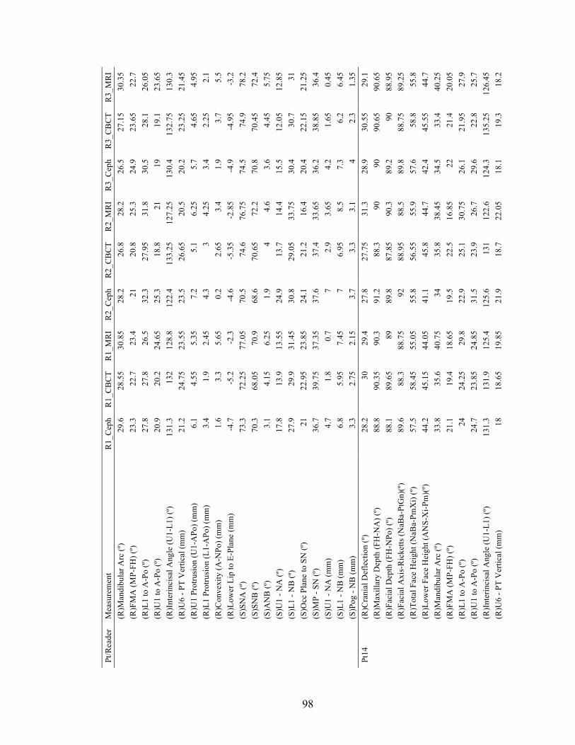
98
Pt/R
eade
r M
easu
rem
ent
R1_
Cep
h R
1_C
BC
T R
1_M
RI
R2_
Cep
h R
2_C
BC
T R
2_M
RI
R3_
Cep
h R
3_C
BC
T R
3_M
RI
(R
)Man
dibu
lar A
rc (º
) 29
.6
28.5
5 30
.85
28.2
26
.8
28.2
26
.5
27.1
5 30
.35
(R
)FM
A (M
P-FH
) (º)
23.3
22
.7
23.4
21
20
.8
25.3
24
.9
23.6
5 22
.7
(R
)L1
to A
-Po
(º)
27.8
27
.8
26.5
32
.3
27.9
5 31
.8
30.5
28
.1
26.0
5
(R)U
1 to
A-P
o (º)
20
.9
20.2
24
.65
25.3
18
.8
21
19
19.1
23
.65
(R
)Int
erin
cisa
l Ang
le (U
1-L1
) (º)
131.
3 13
2 12
8.8
122.
4 13
3.25
12
7.25
13
0.4
132.
75
130.
3
(R)U
6 - P
T V
ertic
al (m
m)
21.2
24
.75
23.5
5 23
.5
26.6
5 20
.5
20.2
23
.25
21.4
5
(R)U
1 Pr
otru
sion
(U1-
APo
) (m
m)
6.1
4.55
5.
35
7.2
5.1
6.25
5.
7 4.
65
4.95
(R)L
1 Pr
otru
sion
(L1-
APo
) (m
m)
3.4
1.9
2.45
4.
3 3
4.25
3.
4 2.
25
2.1
(R
)Con
vexi
ty (A
-NPo
) (m
m)
1.6
3.3
5.65
0.
2 2.
65
3.4
1.9
3.7
5.5
(R
)Low
er L
ip to
E-P
lane
(mm
) -4
.7
-5.2
-2
.3
-4.6
-5
.35
-2.8
5 -4
.9
-4.9
5 -3
.2
(S
)SN
A (º
) 73
.3
72.2
5 77
.05
70.5
74
.6
76.7
5 74
.5
74.9
78
.2
(S
)SN
B (º
) 70
.3
68.0
5 70
.9
68.6
70
.65
72.2
70
.8
70.4
5 72
.4
(S
)AN
B (º
) 3.
1 4.
15
6.25
1.
9 4
4.6
3.6
4.45
5.
75
(S
)U1
- NA
(º)
17.8
13
.9
13.5
5 24
.9
13.7
14
.4
15.5
12
.05
12.8
5
(S)L
1 - N
B (º
) 27
.9
29.9
31
.45
30.8
29
.05
33.7
5 30
.4
30.7
31
(S)O
cc P
lane
to S
N (º
) 21
22
.95
23.8
5 24
.1
21.2
16
.4
20.4
22
.15
21.2
5
(S)M
P - S
N (º
) 36
.7
39.7
5 37
.35
37.6
37
.4
33.6
5 36
.2
38.8
5 36
.4
(S
)U1
- NA
(mm
) 4.
7 1.
8 0.
7 7
2.9
3.65
4.
2 1.
65
0.45
(S)L
1 - N
B (m
m)
6.8
5.95
7.
45
7 6.
95
8.5
7.3
6.2
6.45
(S)P
og -
NB
(mm
) 3.
3 2.
75
2.15
3.
7 3.
3 3.
1 4
2.3
1.35
Pt
14
(R)C
rani
al D
efle
ctio
n (º)
28
.2
30
29.4
27
.8
27.7
5 31
.3
28.9
30
.55
29.1
(R)M
axill
ary
Dep
th (F
H-N
A) (
º) 88
.8
90.3
5 90
.3
91.2
88
.3
90
90
90.6
5 90
.65
(R
)Fac
ial D
epth
(FH
-NPo
) (º)
88.1
89
.65
89
89.8
87
.85
90.3
89
.2
90
88.9
5
(R)F
acia
l Axi
s-R
icke
tts (N
aBa-
PtG
n)(º)
89
.6
88.3
88
.75
92
88.9
5 88
.5
89.8
88
.75
89.2
5
(R)T
otal
Fac
e H
eigh
t (N
aBa-
PmX
i) (º)
57
.5
58.4
5 55
.05
55.8
56
.55
55.9
57
.6
58.8
55
.8
(R
)Low
er F
ace
Hei
ght (
AN
S-X
i-Pm
)(º)
44.2
45
.15
44.0
5 41
.1
45.8
44
.7
42.4
45
.55
44.7
(R)M
andi
bula
r Arc
(º)
33.8
35
.6
40.7
5 34
35
.8
38.4
5 34
.5
33.4
40
.25
(R
)FM
A (M
P-FH
) (º)
21.1
19
.4
18.6
5 19
.5
22.5
16
.85
22
21.4
20
.05
(R
)L1
to A
-Po
(º)
24
24.2
5 29
.8
22.9
25
.1
30.7
5 26
.1
21.9
5 27
.9
(R
)U1
to A
-Po
(º)
24.7
23
.85
24.8
5 31
.5
23.9
26
.7
29.6
22
.8
25.7
(R)I
nter
inci
sal A
ngle
(U1-
L1) (
º) 13
1.3
131.
9 12
5.4
125.
6 13
1 12
2.6
124.
3 13
5.25
12
6.45
(R)U
6 - P
T V
ertic
al (m
m)
18
18.6
5 19
.85
21.9
18
.7
22.0
5 18
.1
19.3
18
.2

99
Pt/R
eade
r M
easu
rem
ent
R1_
Cep
h R
1_C
BC
T R
1_M
RI
R2_
Cep
h R
2_C
BC
T R
2_M
RI
R3_
Cep
h R
3_C
BC
T R
3_M
RI
(R
)U1
Prot
rusi
on (U
1-A
Po) (
mm
) 4.
2 4
4.9
3.9
4.7
6.45
4.
4 4.
4 4.
75
(R
)L1
Prot
rusi
on (L
1-A
Po) (
mm
) 1.
3 0.
75
2.05
0.
7 1.
6 4
1.2
1.3
1.75
(R)C
onve
xity
(A-N
Po) (
mm
) 0.
7 0.
65
1.25
1.
4 0.
45
-0.3
0.
8 0.
65
1.6
(R
)Low
er L
ip to
E-P
lane
(mm
) -5
.7
-6.1
5 -5
.5
-5.4
-5
.95
-5.9
5 -5
.9
-6.3
5 -5
.7
(S
)SN
A (º
) 80
.6
80.5
82
.2
83.3
81
80
.25
81.6
81
83
.4
(S
)SN
B (º
) 78
.3
78
79.3
80
.3
78.7
5 78
.75
78.7
78
.6
80.3
5
(S)A
NB
(º)
2.2
2.5
2.95
3
2.3
1.5
2.9
2.35
3.
05
(S
)U1
- NA
(º)
23.2
22
.5
22.2
5 28
.4
22.9
5 27
.3
27.9
21
.5
22.2
(S)L
1 - N
B (º
) 23
.2
23.1
29
.5
23
23.8
28
.65
25
20.8
5 28
.4
(S
)Occ
Pla
ne to
SN
(º)
14.9
15
.85
15.4
13
.7
13.0
5 16
.05
12.9
12
.75
11.4
5
(S)M
P - S
N (º
) 29
.4
29.2
5 26
.75
27.4
29
.8
26.6
30
.4
31.1
27
.35
(S
)U1
- NA
(mm
) 3.
6 3.
45
3.85
3
4.35
6.
65
3.8
3.85
3.
45
(S
)L1
- NB
(mm
) 3.
7 3.
55
4.85
3.
6 4.
25
6.25
4.
3 3.
95
4.4
(S
)Pog
- N
B (m
m)
2.8
3.5
3 3
3.4
3.45
3.
7 3.
35
2.3
Pt15
(R
)Cra
nial
Def
lect
ion
(º)
31.2
26
.7
26.0
5 28
.5
29
28.4
27
.5
27.0
5 27
.45
(R
)Max
illar
y D
epth
(FH
-NA
) (º)
94
91.9
93
.45
93.5
93
.6
91.7
5 91
.9
91.7
5 93
.05
(R
)Fac
ial D
epth
(FH
-NPo
) (º)
94.3
91
.2
90.3
5 93
.1
93.4
90
.45
91.1
91
.4
92
(R
)Fac
ial A
xis-
Ric
ketts
(NaB
a-Pt
Gn)
(º)
91.9
92
.25
92.7
5 94
.8
92.8
91
.65
94.6
93
.2
93.7
5
(R)T
otal
Fac
e H
eigh
t (N
aBa-
PmX
i) (º)
55
.9
54.8
54
.05
56.6
54
.85
55.1
54
.1
54.4
5 53
.55
(R
)Low
er F
ace
Hei
ght (
AN
S-X
i-Pm
)(º)
41.8
43
.75
42.1
5 43
.5
43.4
5 43
.75
43.9
43
.2
44.1
5
(R)M
andi
bula
r Arc
(º)
39
36.7
35
.1
34.9
34
.35
38.3
5 43
.4
37.4
5 36
.65
(R
)FM
A (M
P-FH
) (º)
17.9
20
.85
19.8
5 21
18
.6
18.0
5 22
.1
21.3
5 17
.45
(R
)L1
to A
-Po
(º)
25.1
22
.4
28.4
5 21
.5
28.2
5 27
.2
22.7
24
.3
28.7
5
(R)U
1 to
A-P
o (º)
23
.4
23.8
33
25
.1
25.3
5 28
.2
26.3
25
.35
30.2
5
(R)I
nter
inci
sal A
ngle
(U1-
L1) (
º) 13
1.5
133.
75
118.
5 13
3.4
126.
4 12
4.55
13
1 13
0.3
120.
95
(R
)U6
- PT
Ver
tical
(mm
) 19
.9
18
16.8
19
.9
21.2
5 19
.95
19.5
17
.85
18.5
5
(R)U
1 Pr
otru
sion
(U1-
APo
) (m
m)
5.4
5.2
5.95
5.
1 5.
8 6.
5 5.
2 5.
45
6.45
(R)L
1 Pr
otru
sion
(L1-
APo
) (m
m)
3.3
2.5
3.25
2.
8 3.
55
4 3.
3 2.
7 2.
55
(R
)Con
vexi
ty (A
-NPo
) (m
m)
-0.2
0.
65
2.95
0.
4 0.
2 1.
2 0.
7 0.
3 1
(R
)Low
er L
ip to
E-P
lane
(mm
) -0
.6
-1.0
5 -0
.7
-0.3
-0
.9
-1.0
5 1.
2 -0
.6
-1
(S
)SN
A (º
) 82
.5
84.1
88
83
.9
84.3
85
.2
84.2
83
.9
88.1
5
(S)S
NB
(º)
81.8
82
.4
83.8
82
.5
83.1
5 83
.05
82.6
82
.5
85.6

100
Pt/R
eade
r M
easu
rem
ent
R1_
Cep
h R
1_C
BC
T R
1_M
RI
R2_
Cep
h R
2_C
BC
T R
2_M
RI
R3_
Cep
h R
3_C
BC
T R
3_M
RI
(S
)AN
B (º
) 0.
7 1.
6 4.
2 1.
5 1.
15
2.1
1.6
1.4
2.6
(S
)U1
- NA
(º)
23.9
22
.35
26.1
24
.2
24.9
25
.5
24.7
24
.65
27.9
5
(S)L
1 - N
B (º
) 23
.8
22.2
31
.2
20.9
27
.6
27.8
22
.7
23.6
5 28
.5
(S
)Occ
Pla
ne to
SN
(º)
17.7
18
.75
13.9
16
.3
15.3
5 13
.7
17.5
16
.1
9.25
(S)M
P - S
N (º
) 29
.4
28.7
25
.3
30.5
27
.9
24.6
29
.8
29.2
22
.4
(S
)U1
- NA
(mm
) 5.
6 4.
6 3.
65
4.8
5.65
5.
55
4.6
5.2
5.65
(S)L
1 - N
B (m
m)
4.4
4.15
6.
4 4.
4 4.
9 5.
7 4.
9 4.
25
5.1
(S
)Pog
- N
B (m
m)
1.8
1.7
1.8
1.9
1.65
1.
4 1.
5 1.
85
2.6
Pt16
(R
)Cra
nial
Def
lect
ion
(º)
27.6
27
.6
27.2
27
.3
29.8
28
.45
21.4
27
.2
26.5
5
(R)M
axill
ary
Dep
th (F
H-N
A) (
º) 93
.4
92.4
5 92
.25
90.3
95
.1
93.1
5 86
.6
91.9
5 93
.45
(R
)Fac
ial D
epth
(FH
-NPo
) (º)
94.1
92
.5
92.4
92
.8
95.1
5 94
.25
87.6
92
.2
93.2
5
(R)F
acia
l Axi
s-R
icke
tts (N
aBa-
PtG
n)(º)
98
.6
95.4
5 97
.65
98.5
96
.2
97.2
5 99
.2
96.5
99
.6
(R
)Tot
al F
ace
Hei
ght (
NaB
a-Pm
Xi)
(º)
45.9
48
.75
45.4
47
48
.2
45.0
5 43
.6
46.6
43
.7
(R
)Low
er F
ace
Hei
ght (
AN
S-X
i-Pm
)(º)
33.4
36
.55
37.0
5 35
.6
36.1
5 37
.1
35.2
35
.55
36.1
(R)M
andi
bula
r Arc
(º)
42.1
39
.75
42.9
40
.2
40.4
42
.4
44.1
41
.75
43.9
(R)F
MA
(MP-
FH) (
º) 11
.9
13.0
5 10
.7
13.6
11
.35
10
18.9
15
.4
12.1
5
(R)L
1 to
A-P
o (º)
19
.2
22.7
5 22
.5
26
21.8
5 29
.5
22.8
22
.75
26.0
5
(R)U
1 to
A-P
o (º)
23
.2
18.8
5 19
.7
24.5
17
.2
16.7
22
.3
18.4
5 18
.95
(R
)Int
erin
cisa
l Ang
le (U
1-L1
) (º)
137.
6 13
8.35
13
7.8
129.
5 14
0.9
133.
85
134.
9 13
8.85
13
4.95
(R)U
6 - P
T V
ertic
al (m
m)
24.9
24
.45
25.9
24
.4
28.3
5 27
.25
21.6
24
.7
25.8
(R)U
1 Pr
otru
sion
(U1-
APo
) (m
m)
1.5
1.5
2.55
2.
5 2.
05
2.7
1.6
1.55
1.
4
(R)L
1 Pr
otru
sion
(L1-
APo
) (m
m)
-2.2
-1
.8
-0.7
5 -0
.2
-1.1
5 0.
75
-1.2
-1
.6
-1.6
5
(R)C
onve
xity
(A-N
Po) (
mm
) -0
.7
-0.0
5 -0
.1
-2.4
-0
.05
-1
-1
-0.3
0.
2
(R)L
ower
Lip
to E
-Pla
ne (m
m)
-5.8
-5
-4
.1
-5.3
-4
.65
-5.0
5 -6
-5
.35
-5.0
5
(S)S
NA
(º)
84.2
83
.9
83.8
81
.9
84.6
85
.95
83.1
83
.5
86.3
5
(S)S
NB
(º)
81.4
81
.4
81.2
5 81
.1
81.2
5 83
.9
80.9
80
.85
83.0
5
(S)A
NB
(º)
2.8
2.5
2.5
0.8
3.35
2.
1 2.
3 2.
65
3.25
(S)U
1 - N
A (º
) 24
.7
18.9
5 20
29
.9
17.3
18
.95
24.7
19
18
.5
(S
)L1
- NB
(º)
14.9
20
.2
19.7
5 19
.9
18.4
25
.15
18.2
19
.5
23.2
5
(S)O
cc P
lane
to S
N (º
) 9.
4 8.
55
10.7
9
8.15
5.
85
7.6
8.1
8.85
(S)M
P - S
N (º
) 21
21
.6
19.2
22
21
.85
17.2
5 22
.4
23.8
5 19
.3
(S
)U1
- NA
(mm
) 1.
9 1.
55
2.6
4.2
2.05
3.
55
2.2
1.75
1.
25

101
Pt/R
eade
r M
easu
rem
ent
R1_
Cep
h R
1_C
BC
T R
1_M
RI
R2_
Cep
h R
2_C
BC
T R
2_M
RI
R3_
Cep
h R
3_C
BC
T R
3_M
RI
(S
)L1
- NB
(mm
) 1.
6 1.
45
2.45
2.
2 3.
05
3.9
2.1
1.9
2.25
(S)P
og -
NB
(mm
) 6.
3 4.
75
4.75
6
6.25
5.
65
5.9
5.4
5.5
Pt17
(R
)Cra
nial
Def
lect
ion
(º)
29.1
30
.5
28.6
28
.9
30.2
29
.9
28.2
30
.25
32
(R
)Max
illar
y D
epth
(FH
-NA
) (º)
89
89.8
5 89
.5
86.8
89
.25
90.1
87
.9
89.5
91
.3
(R
)Fac
ial D
epth
(FH
-NPo
) (º)
87.5
88
.1
87.3
5 87
.2
87.9
87
.85
86.4
87
.9
89.2
5
(R)F
acia
l Axi
s-R
icke
tts (N
aBa-
PtG
n)(º)
86
.7
84.8
86
.65
88.7
85
.55
87.4
5 88
85
.6
85.5
5
(R)T
otal
Fac
e H
eigh
t (N
aBa-
PmX
i) (º)
62
.4
63.6
5 61
.85
60.8
63
.05
62.2
61
.8
64.1
5 64
.05
(R
)Low
er F
ace
Hei
ght (
AN
S-X
i-Pm
)(º)
49.8
50
.5
51.3
50
.2
50.5
5 50
.5
48.7
51
52
.05
(R
)Man
dibu
lar A
rc (º
) 33
.6
32.5
5 32
.9
32.8
31
.6
29.0
5 32
.9
32.4
5 32
.7
(R
)FM
A (M
P-FH
) (º)
27.4
27
27
.5
26
27.4
5 23
.5
29
28.6
5 25
.25
(R
)L1
to A
-Po
(º)
16.6
19
.3
22.7
19
.1
18.8
5 20
.65
18.8
19
.6
20.8
5
(R)U
1 to
A-P
o (º)
17
17
.35
23.5
20
.1
16.7
27
.95
18.5
13
.9
16.4
(R)I
nter
inci
sal A
ngle
(U1-
L1) (
º) 14
6.4
143.
35
133.
8 14
0.8
144.
4 13
1.4
142.
7 14
6.5
142.
7
(R)U
6 - P
T V
ertic
al (m
m)
19
21.3
5 21
.05
22
22.8
5 22
.95
20.3
21
.25
22.2
(R)U
1 Pr
otru
sion
(U1-
APo
) (m
m)
3.8
3.75
4.
85
5.1
4.2
3.9
3.7
3.75
3.
7
(R)L
1 Pr
otru
sion
(L1-
APo
) (m
m)
1.7
1 2.
5 2.
5 1.
6 0.
55
1.6
1.2
2.2
(R
)Con
vexi
ty (A
-NPo
) (m
m)
1.5
1.75
2
-0.4
1.
35
2.2
1.5
1.6
2.05
(R)L
ower
Lip
to E
-Pla
ne (m
m)
-4.7
-5
.8
-4.6
5 -5
-5
.9
-4.3
5 -4
.1
-5.6
5 -4
.8
(S
)SN
A (º
) 80
.6
80
79.9
5 77
.6
79.9
5 81
.55
80.2
80
80
.05
(S
)SN
B (º
) 78
.3
77.1
76
.75
76.8
77
.3
77.8
5 77
.5
77.3
77
.3
(S
)AN
B (º
) 2.
3 2.
9 3.
3 0.
8 2.
6 3.
7 2.
7 2.
65
2.75
(S)U
1 - N
A (º
) 14
13
.95
19.4
5 20
.9
14.1
23
.65
15.5
10
.8
12.5
(S)L
1 - N
B (º
) 17
.4
19.8
23
.45
17.4
18
.9
21.3
19
20
22
.05
(S
)Occ
Pla
ne to
SN
(º)
14.6
18
.35
20.5
16
.2
18
12.7
14
.5
18.7
16
.4
(S
)MP
- SN
(º)
35.7
36
.85
37
35.2
36
.7
32
36.6
38
.15
36.4
5
(S)U
1 - N
A (m
m)
2.5
2.15
3
5.5
3.05
2.
25
2.5
2.25
1.
9
(S)L
1 - N
B (m
m)
3.8
3.65
5.
35
4 4.
2 4
4.3
3.75
4.
45
(S
)Pog
- N
B (m
m)
1.6
2.4
2.3
2.5
2.6
3.05
2.
6 2.
3 1.
4 Pt
18
(R)C
rani
al D
efle
ctio
n (º)
31
.5
30.5
27
.95
28.4
32
.3
29.5
5 28
.8
28.6
28
.85
(R
)Max
illar
y D
epth
(FH
-NA
) (º)
92.5
91
.45
88.5
89
.7
92.5
87
.4
89.9
89
.7
89.8
(R)F
acia
l Dep
th (F
H-N
Po) (
º) 91
.4
90.1
5 88
.4
89.2
91
.5
88.7
5 88
.5
87.9
89
.05
(R
)Fac
ial A
xis-
Ric
ketts
(NaB
a-Pt
Gn)
(º)
90.9
89
.05
91.6
93
88
.65
89.7
5 91
.7
89.2
5 91
.65

102
Pt/R
eade
r M
easu
rem
ent
R1_
Cep
h R
1_C
BC
T R
1_M
RI
R2_
Cep
h R
2_C
BC
T R
2_M
RI
R3_
Cep
h R
3_C
BC
T R
3_M
RI
(R
)Tot
al F
ace
Hei
ght (
NaB
a-Pm
Xi)
(º)
53.2
53
.35
51.9
5 53
.5
54.2
5 53
.3
54.1
54
.5
52
(R
)Low
er F
ace
Hei
ght (
AN
S-X
i-Pm
)(º)
38.3
38
.9
40.3
39
.1
39.8
45
.2
39.8
40
.6
39.9
5
(R)M
andi
bula
r Arc
(º)
41.5
40
.85
43.7
37
.9
39.9
5 37
.4
43.5
41
43
.35
(R
)FM
A (M
P-FH
) (º)
15.4
15
.2
12.2
16
.9
13.7
5 13
.45
17.4
19
.05
14.9
5
(R)L
1 to
A-P
o (º)
25
.7
28.5
5 29
.25
28.1
27
.9
24.4
5 27
.7
27.4
25
.25
(R
)U1
to A
-Po
(º)
25.1
21
.8
22.2
24
.5
20.1
23
.85
27.7
22
.2
22.2
(R)I
nter
inci
sal A
ngle
(U1-
L1) (
º) 12
9.1
129.
7 12
8.55
12
7.4
132
131.
7 12
4.6
130.
45
132.
6
(R)U
6 - P
T V
ertic
al (m
m)
24.2
22
.3
22.6
5 24
.9
24.5
5 23
.65
23.2
20
.15
21.9
(R)U
1 Pr
otru
sion
(U1-
APo
) (m
m)
3.1
2 3.
5 3.
3 2.
95
5.3
3 2.
55
2.65
(R)L
1 Pr
otru
sion
(L1-
APo
) (m
m)
0.5
-1.1
1
0.9
0.25
1.
4 0.
5 -0
.1
-1
(R
)Con
vexi
ty (A
-NPo
) (m
m)
1.1
1.4
0.1
0.5
1.1
-1.4
1.
5 1.
95
0.75
(R)L
ower
Lip
to E
-Pla
ne (m
m)
-4.4
-6
.7
-5.5
-5
.5
-6.7
-5
.8
-5.6
-6
.55
-6.3
5
(S)S
NA
(º)
84.1
84
.85
83.3
5 83
.8
84.5
5 82
.05
84.7
84
.95
85.2
(S)S
NB
(º)
81
81.1
5 81
.35
81.1
81
.35
81.3
5 81
.3
81.1
82
.2
(S
)AN
B (º
) 3.
1 3.
7 2
2.7
3.2
0.7
3.4
3.8
2.95
(S)U
1 - N
A (º
) 22
.7
18.9
22
23
.3
17.9
5 26
.7
24.6
18
.25
20.5
5
(S)L
1 - N
B (º
) 25
.1
27.7
27
.4
26.5
26
.9
20.8
5 27
.4
27.5
5 23
.85
(S
)Occ
Pla
ne to
SN
(º)
8.3
9.6
7.45
8.
7 10
.3
7.6
8.1
10.5
8.
2
(S)M
P - S
N (º
) 23
.8
21.8
17
.4
22.8
21
.7
18.8
22
.7
23.8
19
.55
(S
)U1
- NA
(mm
) 2.
2 0.
9 3.
45
2.8
2.05
6.
35
1.8
1.05
2.
1
(S)L
1 - N
B (m
m)
3.8
3.1
3.6
4.2
3.9
3.25
4
3.9
2.45
(S)P
og -
NB
(mm
) 3.
7 4.
65
3.65
4.
1 4.
2 4
3.7
3.9
4.35
Pt
19
(R)C
rani
al D
efle
ctio
n (º)
31
33
.15
32.5
5 29
.9
33.4
32
.25
31.4
33
.65
33.3
(R)M
axill
ary
Dep
th (F
H-N
A) (
º) 91
92
.2
91.2
93
93
.5
93.2
5 91
.5
92.5
93
.1
(R
)Fac
ial D
epth
(FH
-NPo
) (º)
89.5
90
.55
88.6
90
.6
91.6
5 89
.7
90.3
90
.75
90.5
5
(R)F
acia
l Axi
s-R
icke
tts (N
aBa-
PtG
n)(º)
84
.1
81.7
5 81
.85
85.6
82
.45
82.5
85
.3
82
82.4
5
(R)T
otal
Fac
e H
eigh
t (N
aBa-
PmX
i) (º)
62
.9
63.3
65
.8
63.3
61
.9
62.2
62
.2
63.9
5 62
.9
(R
)Low
er F
ace
Hei
ght (
AN
S-X
i-Pm
)(º)
46.8
47
.15
47.8
48
.4
48.6
5 48
.2
48.3
47
.7
46.3
5
(R)M
andi
bula
r Arc
(º)
38.6
39
.75
37.8
5 34
.6
38.8
36
.4
40.6
39
.55
42.6
5
(R)F
MA
(MP-
FH) (
º) 24
.8
22.6
5 23
.2
23.4
21
.95
21.1
5 23
.6
24
21.4
(R)L
1 to
A-P
o (º)
26
.5
28.2
5 28
.05
27.2
27
.45
27.3
23
.5
25.7
24
.4
(R
)U1
to A
-Po
(º)
22.2
21
.8
23.2
23
.5
21.3
25
.95
22.1
21
.75
22.8
5

103
Pt/R
eade
r M
easu
rem
ent
R1_
Cep
h R
1_C
BC
T R
1_M
RI
R2_
Cep
h R
2_C
BC
T R
2_M
RI
R3_
Cep
h R
3_C
BC
T R
3_M
RI
(R
)Int
erin
cisa
l Ang
le (U
1-L1
) (º)
131.
3 12
9.9
128.
75
129.
3 13
1.25
12
6.75
13
4.4
132.
5 13
2.75
(R)U
6 - P
T V
ertic
al (m
m)
18.9
19
.35
18.9
5 19
.6
21.6
20
.75
19.8
19
.7
18.2
5
(R)U
1 Pr
otru
sion
(U1-
APo
) (m
m)
4.9
5.5
5.65
5.
7 5.
7 6.
6 5.
6 5.
55
5
(R)L
1 Pr
otru
sion
(L1-
APo
) (m
m)
1.5
1.9
0.55
2.
3 1.
95
3.15
1.
8 1.
25
1.1
(R
)Con
vexi
ty (A
-NPo
) (m
m)
1.7
1.8
3 2.
5 2
3.85
1.
4 2
2.9
(R
)Low
er L
ip to
E-P
lane
(mm
) -0
.3
0.1
1.1
0.2
10.8
1.
25
0.6
0.15
0.
75
(S
)SN
A (º
) 80
.8
80
80.0
5 84
.7
81
84.9
5 79
.5
79.7
5 83
.2
(S
)SN
B (º
) 77
.1
76.3
5 75
.6
80.5
77
.2
80.0
5 76
.1
76.2
5 78
.8
(S
)AN
B (º
) 3.
7 3.
65
4.45
4.
2 3.
8 4.
9 3.
4 3.
5 4.
35
(S
)U1
- NA
(º)
18.9
18
.55
17.6
5 18
.5
17.5
18
.55
19.5
18
.1
17.4
(S)L
1 - N
B (º
) 26
.1
27.9
29
.2
28
27.4
5 29
.75
22.7
25
.9
25.5
(S)O
cc P
lane
to S
N (º
) 15
.7
17.2
5 18
.55
13.1
16
.5
11
15.1
17
.25
13.2
(S)M
P - S
N (º
) 35
34
.85
34.4
31
.7
34.4
5 29
.5
35.6
36
.75
31.3
5
(S)U
1 - N
A (m
m)
3.5
3.9
3.3
3.7
3.85
3.
5 4.
4 3.
8 2.
65
(S
)L1
- NB
(mm
) 5.
6 6
5.2
6.5
6.15
7.
45
5.9
5.1
5.6
(S
)Pog
- N
B (m
m)
4.4
4.35
3.
95
3.7
4.2
2.65
4.
5 3.
7 3.
85
Pt20
(R
)Cra
nial
Def
lect
ion
(º)
28.9
28
.15
28.8
25
.2
26.6
5 29
.4
25.6
28
.3
29.3
5
(R)M
axill
ary
Dep
th (F
H-N
A) (
º) 90
.2
90.5
5 90
.45
86.3
89
.8
90.3
5 88
.7
90.7
5 92
.65
(R
)Fac
ial D
epth
(FH
-NPo
) (º)
83.6
83
.8
83.5
81
.4
83.8
5 82
.7
81.4
83
.8
85.2
5
(R)F
acia
l Axi
s-R
icke
tts (N
aBa-
PtG
n)(º)
80
.8
79.9
80
.05
82.6
81
.6
78
83.7
81
.3
81
(R
)Tot
al F
ace
Hei
ght (
NaB
a-Pm
Xi)
(º)
68
69.2
5 66
.65
68
64.9
5 64
.5
66.1
69
.8
65.8
5
(R)L
ower
Fac
e H
eigh
t (A
NS-
Xi-P
m)(
º) 46
.5
49.1
5 48
.6
46.5
49
.1
50.0
5 45
.6
49.4
5 47
.45
(R
)Man
dibu
lar A
rc (º
) 32
26
.5
34.0
5 28
.4
32.4
42
.2
35.6
27
.4
33.2
5
(R)F
MA
(MP-
FH) (
º) 33
32
.55
29.5
5 34
.3
33.6
5 29
.3
34.2
34
30
.4
(R
)L1
to A
-Po
(º)
22.3
23
.15
24.9
30
27
.5
33.5
5 25
.1
24.1
24
.9
(R
)U1
to A
-Po
(º)
30
26.6
30
.7
28.8
26
.15
30.7
34
.7
26.3
30
.75
(R
)Int
erin
cisa
l Ang
le (U
1-L1
) (º)
127.
8 13
0.3
124.
4 12
1.2
126.
35
115.
7 12
0.1
129.
6 12
4.25
(R)U
6 - P
T V
ertic
al (m
m)
14.4
12
.9
13.4
5 11
.9
15.6
15
12
.3
13.8
5 12
.9
(R
)U1
Prot
rusi
on (U
1-A
Po) (
mm
) 8.
2 7.
65
7.7
9.9
9.05
10
.75
8.4
7.9
7.6
(R
)L1
Prot
rusi
on (L
1-A
Po) (
mm
) 3.
7 2.
95
2.75
5.
7 5.
05
5.8
3.3
3.45
2.
7
(R)C
onve
xity
(A-N
Po) (
mm
) 7.
6 7.
7 7.
95
5.4
6.35
8.
3 8.
1 7.
9 8.
45
(R
)Low
er L
ip to
E-P
lane
(mm
) 0.
8 0.
75
1.7
0.8
1 1
0.9
0.65
1.
25

104
Pt/R
eade
r M
easu
rem
ent
R1_
Cep
h R
1_C
BC
T R
1_M
RI
R2_
Cep
h R
2_C
BC
T R
2_M
RI
R3_
Cep
h R
3_C
BC
T R
3_M
RI
(S
)SN
A (º
) 81
.1
83.6
5 84
.15
81.9
85
.85
84.7
84
.4
84.6
86
.3
(S
)SN
B (º
) 73
.6
76.0
5 76
.75
76.2
78
.8
76.8
76
.3
77
78.2
5
(S)A
NB
(º)
7.5
7.6
7.4
5.8
7.05
7.
85
8.1
7.6
8.05
(S)U
1 - N
A (º
) 15
11
.3
14.4
17
.8
13.4
14
18
.5
10.8
5 13
.5
(S
)L1
- NB
(º)
29.8
30
.85
33.7
5 35
.2
33.2
5 42
.4
33.3
31
.95
34.2
(S)O
cc P
lane
to S
N (º
) 20
.9
20.3
5 21
19
.6
19.8
5 20
.6
19
20.6
18
.8
(S
)MP
- SN
(º)
42.1
39
.45
35.9
38
.7
37.5
5 34
.9
38.5
40
.15
36.7
(S)U
1 - N
A (m
m)
2.2
1.6
2 5.
5 3.
65
4.35
1.
9 1.
6 1.
5
(S)L
1 - N
B (m
m)
9.8
9.25
8.
65
10.2
10
.5
11.4
9.
4 9.
5 9.
15
(S
)Pog
- N
B (m
m)
1.8
1.65
0.
95
1.6
2.15
0.
6 1.
5 1.
3 1.
25
Pt21
(R
)Cra
nial
Def
lect
ion
(º)
27.7
27
.55
24.4
28
.5
26.2
25
.8
27.2
28
.55
28.9
5
(R)M
axill
ary
Dep
th (F
H-N
A) (
º) 94
.2
93.9
96
.6
94.7
94
.8
92.5
93
94
.45
93.3
(R)F
acia
l Dep
th (F
H-N
Po) (
º) 88
.5
87.9
5 88
89
.5
88.8
87
.25
88.2
88
.6
87.2
5
(R)F
acia
l Axi
s-R
icke
tts (N
aBa-
PtG
n)(º)
86
.6
86.2
5 89
86
.4
88.7
87
.2
87.8
86
.95
84.6
(R)T
otal
Fac
e H
eigh
t (N
aBa-
PmX
i) (º)
55
.5
55.6
5 52
.35
56.2
51
.1
56.4
5 52
.8
56
59.8
5
(R)L
ower
Fac
e H
eigh
t (A
NS-
Xi-P
m)(
º) 42
.2
43.1
5 41
.7
42.7
42
.3
50.8
40
.9
43.1
44
.2
(R
)Man
dibu
lar A
rc (º
) 39
.5
38.3
5 39
.7
40.3
43
.35
39.7
44
.2
39.6
36
.25
(R
)FM
A (M
P-FH
) (º)
18.3
15
.85
16.0
5 15
.1
17.5
5 15
.5
18.1
18
.05
18.4
5
(R)L
1 to
A-P
o (º)
30
.7
37.5
36
.45
32.9
38
.1
27.9
34
.6
37.3
35
.65
(R
)U1
to A
-Po
(º)
31.1
32
.25
37.9
33
.2
30.4
30
.9
35.2
31
.1
35.7
(R)I
nter
inci
sal A
ngle
(U1-
L1) (
º) 11
8.2
110.
25
105.
65
114
111.
5 12
1.2
110.
2 11
1.55
10
8.65
(R)U
6 - P
T V
ertic
al (m
m)
18.8
19
.45
19.9
5 19
.8
21.9
22
.05
18.1
21
.25
19
(R
)U1
Prot
rusi
on (U
1-A
Po) (
mm
) 8.
2 8.
4 8.
6 8.
7 8.
65
8.85
8.
8 8.
55
8.95
(R)L
1 Pr
otru
sion
(L1-
APo
) (m
m)
5.7
6.15
5.
55
6.1
6.8
5.85
6.
3 6.
5 6.
55
(R
)Con
vexi
ty (A
-NPo
) (m
m)
6.3
6.65
9
5.6
6.2
5.4
5 6.
55
7.05
(R)L
ower
Lip
to E
-Pla
ne (m
m)
1.4
2.9
4.55
0.
6 2.
05
5.05
2.
2 2.
05
3.75
(S)S
NA
(º)
83.7
83
.25
91.5
83
.5
86.9
5 87
.85
82.4
83
.6
82.7
5
(S)S
NB
(º)
77.1
76
.35
82.5
77
.3
80.1
5 81
.75
76.9
77
.45
76.4
5
(S)A
NB
(º)
6.6
6.9
9 6.
2 6.
85
6.15
5.
5 6.
15
6.25
(S)U
1 - N
A (º
) 19
19
.5
19.8
22
.3
18.1
5 20
.35
24.6
18
.7
22.5
(S)L
1 - N
B (º
) 36
.1
43.3
45
.6
37.5
43
.55
32.3
39
.7
43.5
42
.55
(S
)Occ
Pla
ne to
SN
(º)
19.7
21
17
.75
21.2
18
.65
15.1
5 20
.9
21.5
21
.45

105
Pt/R
eade
r M
easu
rem
ent
R1_
Cep
h R
1_C
BC
T R
1_M
RI
R2_
Cep
h R
2_C
BC
T R
2_M
RI
R3_
Cep
h R
3_C
BC
T R
3_M
RI
(S
)MP
- SN
(º)
28.8
26
.5
21.1
5 26
.2
25.3
20
.1
28.7
28
.85
28.9
5
(S)U
1 - N
A (m
m)
3.7
3.15
2
4.4
3.9
4.85
5.
2 3.
45
3.95
(S)L
1 - N
B (m
m)
11
11.5
5 11
.85
11.1
11
.95
10.6
10
.4
11
11.3
5
(S)P
og -
NB
(mm
) 1.
9 1.
9 0.
8 2.
1 1.
8 1.
9 1.
4 0.
65
0.6
Pt22
(R
)Cra
nial
Def
lect
ion
(º)
32.2
34
.35
32.8
31
.6
35.3
34
.85
31.4
32
.75
40.7
5
(R)M
axill
ary
Dep
th (F
H-N
A) (
º) 89
.9
91.9
5 91
.2
90.6
92
.5
91.5
5 89
.3
90.9
5 98
.65
(R
)Fac
ial D
epth
(FH
-NPo
) (º)
86.5
88
.3
87.8
87
.7
89.8
88
.65
86.7
87
.6
95.6
(R)F
acia
l Axi
s-R
icke
tts (N
aBa-
PtG
n)(º)
78
.3
77.7
80
.2
80.8
79
.05
79.5
5 79
.6
79.1
5 80
.1
(R
)Tot
al F
ace
Hei
ght (
NaB
a-Pm
Xi)
(º)
66.6
66
.1
64.2
5 65
.6
65.9
5 67
.65
65.4
66
.4
65
(R
)Low
er F
ace
Hei
ght (
AN
S-X
i-Pm
)(º)
56.4
56
.35
50.8
58
.4
55.6
56
.9
56.7
56
.15
52.8
5
(R)M
andi
bula
r Arc
(º)
32
34.5
32
.85
31.5
32
.45
28.5
32
.7
32.4
35
.1
(R
)FM
A (M
P-FH
) (º)
31.1
28
.4
28.3
5 29
.8
27.9
24
.6
32.7
30
.85
18.9
(R)L
1 to
A-P
o (º)
26
.4
27.0
5 29
.25
26.5
25
.8
28
30.5
28
.6
27.1
5
(R)U
1 to
A-P
o (º)
28
.9
27.3
5 26
.75
29.4
24
.7
28.5
5 29
.2
26.5
5 28
.35
(R
)Int
erin
cisa
l Ang
le (U
1-L1
) (º)
124.
7 12
5.6
123.
95
124.
1 12
9.5
123.
45
120.
3 12
4.9
124.
5
(R)U
6 - P
T V
ertic
al (m
m)
20.2
22
22
.7
21.4
24
.15
27.4
5 21
.6
22.0
5 30
.1
(R
)U1
Prot
rusi
on (U
1-A
Po) (
mm
) 7.
9 7.
5 7.
1 8.
2 8.
05
11.0
5 8.
7 7.
55
8.4
(R
)L1
Prot
rusi
on (L
1-A
Po) (
mm
) 4.
1 3.
85
3.7
3.8
4.9
7.55
4.
8 4.
25
4.65
(R)C
onve
xity
(A-N
Po) (
mm
) 3.
6 3.
85
3.55
3
2.8
3.05
2.
7 3.
5 3.
25
(R
)Low
er L
ip to
E-P
lane
(mm
) 3.
4 2.
05
2.8
4.3
2.15
3.
4 2.
8 2
2.9
(S
)SN
A (º
) 77
.7
77.4
80
.25
77.4
77
.55
80.2
76
.4
77.8
5 78
.5
(S
)SN
B (º
) 73
.8
73.4
76
.2
74
74.1
5 77
.25
73.3
74
.15
75.6
5
(S)A
NB
(º)
3.9
4 4.
1 3.
4 3.
3 2.
95
3.1
3.7
2.8
(S
)U1
- NA
(º)
22.3
20
.3
19.6
5 23
.7
19.5
22
.7
24.1
20
.05
22.2
(S)L
1 - N
B (º
) 29
.2
30.0
5 32
.3
28.9
27
.65
30.8
5 32
.5
31.3
5 30
.45
(S
)Occ
Pla
ne to
SN
(º)
22.1
20
.45
19.4
24
.5
19.6
5 15
.6
21.8
19
.45
15.8
(S)M
P - S
N (º
) 43
.3
42.9
39
.2
43
42.8
5 35
.95
45.6
43
.9
39.0
5
(S)U
1 - N
A (m
m)
4.8
4.1
3.9
5.5
5.6
8.45
6.
3 4.
45
5.75
(S)L
1 - N
B (m
m)
6.9
6.65
6.
65
6.2
7.55
9.
45
7.1
6.9
6.25
(S)P
og -
NB
(mm
) 1.
1 0.
8 1.
35
1 1.
5 0.
1 1
0.85
-0
.5
![FRONT VIEW TOP VIEW SIDE VIEW - Dent Unit · FRONT VIEW TOP VIEW SIDE VIEW Function ... [TB&PNS] · 17 x 11[Airway ... [Lateral], Auto Ceph[SMV] and Auto Ceph[Waters’ view]. The](https://img.pdfslide.net/doc/110x75/5ac40a767f8b9a57528cd1a6/front-view-top-view-side-view-dent-view-top-view-side-view-function-tbpns.jpg)