Embed Size (px)
Citation preview

23
Comparison between Different Supply Port Configurations in Gas Journal Bearings
Federico Colombo Terenziano Raparelli and Vladimir Viktorov Politecnico di Torino Department of Mechanics
Italy
1 Introduction
Because of their precision gas bearings are widely used for very high speed spindle applications Compared to conventional oil bearings gas bearings generate less heat and do not pollute the environment Air viscosity is three orders of magnitude lower than oil so the power dissipated in gas bearings is very low The major disadvantage of these bearings is rotor whirl instability which restricts the possible range of applications Researchers have studied this problem using different methods since the 60s Gross first
applied a perturbation method to evaluate the stability of an infinitely long journal bearing
(Gross amp Zachmanaglou 1961) Galerkinrsquos method was used by others to calculate rotor
speed and mass at the stability threshold (Cheng amp Pan 1965) Lund investigated the
stiffness and damping coefficients of hydrostatic gas bearing and used these coefficients to
investigate whirl instability (Lund 1968) Wadhwa et al adapted the perturbation method
to calculate the dynamic coefficients and to study the stability of a rotor supported by orifice
compensated gas bearings (Wadhwa et al 1983) Results show that aerostatic bearings have
a larger load capacity and higher stability than plain journal bearings Han et al proved that
more circumferential supply ports result in increased stiffness coefficient but reduced
damping (Han et al 1994) Others found that orifice-compensated and shallow-pocket type
hybrid gas journal bearings offer better stability than eight-orifice type bearings (Zhang amp
Chang 1995)
Also porous journal bearings were studied (Sun 1975) and compared against hybrid gas
bearings with multi-array entries (Su amp Lie 2006) (Heller et al 1971) Despite the fact that
damping is generally higher in porous bearings than in aerostatic bearings the results of (Su
amp Lie 2006) suggest that at high operating speeds multi-array entry bearings are more
stable than porous bearings
Other studies (Andres 1990) (Sawcki et al 1997) (Yoshikawa et al 1999) considered
various pressurized air compensated configurations but very few papers analysed the
influence of the number and location of entry ports
In (Su amp Lie 2003) hybrid air journal bearings with multi-array supply orifices were
compared to porous bearings One to five rows of orifices were considered It was found
that five rows of supply orifices perform as well as porous bearings whilst supply orifice
feeding has the advantage of consuming less power than porous feeding Paper (Yang et al
2009) compared bearing systems with double-array orifice restrictions to three and six entry
wwwintechopencom
New Tribological Ways
478
systems Results show that the stability threshold is better with six-ports than with three
ports
In (Colombo et al 2009) the authors analysed two externally pressurized gas bearings one with a central row of supply orifices the other with a double row The supply port downstream pressure was found to be proportional to the critical mass At this pressure reading the second bearing type was 30 stiffer and 50 more stable The aim of this work is to compare three externally pressurized gas journal bearings at given air consumption rates The idea was to investigate which offers the best spatial distribution of supply orifices under the same pneumatic power The study compared radial stiffness and pressure distribution for the three bearing types also evaluating the damping factor and the whirl ratio of the shaft The stability threshold was calculated for different restriction parameters so that the proposed bearing types could be compared
2 Description of the problem
The object of the study was a rigid rotor supported by two identical gas journal bearings situated symmetrically with respect to the journal centre The rotor with diameter D=50 mm was considered to be perfectly balanced The radial air clearance was h0=20 microm and the bearings had LD ratio equal to unity Three bearing types were considered as illustrated in figure 1 Bearing type 1 featured four supply ports situated in the centre plane of the bearing bearing type 2 featured two sets of supply ports situated at z=L4 and z=3L4 bearing type 3 also featured a central vented circumferential chamber The three bearing types were comparable in terms of stiffness and damping coefficients air consumption and stability In (Colombo et al 2009) the authors compared bearing types 1 and 2 (see figure 1) considering the same supply port diameter ds The bearing with double array entries (bearing type 2) was found to be 30 stiffer than the one with a single central array (bearing type 1) but the air consumption was two times as much Moreover bearing 2 was more stable the rotor mass at incipient whirl instability was about 50 greater Another point of interest was which bearing type was to be preferred for the same level of air consumption In this paper the bearings illustrated in figure 1 were compared considering different supply port diameters in order to have the same air consumption
3 Lubrication analysis
31 Mathematical model
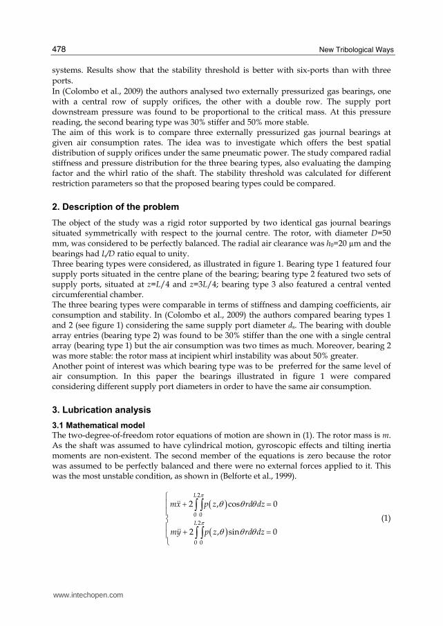
The two-degree-of-freedom rotor equations of motion are shown in (1) The rotor mass is m As the shaft was assumed to have cylindrical motion gyroscopic effects and tilting inertia moments are non-existent The second member of the equations is zero because the rotor was assumed to be perfectly balanced and there were no external forces applied to it This was the most unstable condition as shown in (Belforte et al 1999)
( )( )
2
0 0
2
0 0
2 cos 0
2 sin 0
L
L
mx p z rd dz
my p z rd dz
π
πθ θ θ
θ θ θ
⎧ + =⎪⎪⎨⎪ + =⎪⎩
int intint int
$$
$$ (1)
wwwintechopencom
Comparison between Different Supply Port Configurations in Gas Journal Bearings
479
Fig 1 Bearing types under study
The pressure distribution in clearance h was calculated solving the distributed parameters problem described by the Reynolds equation for a compressible-fluid-film journal bearing (2) assuming isothermal gas expansion
( ) ( )3 3 0 012 6 12ph php p G
ph ph R Tz z r r rdrd t
μ μω μθ θ θ θpart partpart partpart part⎛ ⎞ ⎛ ⎞+ + = +⎜ ⎟ ⎜ ⎟part part part part part part⎝ ⎠ ⎝ ⎠ (2)
Mass flow rate G at supply orifice was calculated in accordance with the isentropic expansion formula (3) corrected by experimentally identified discharge coefficient cd expressed by eq (4) Reynolds number at the supply hole was calculated as per equation (5) Formula (4) is the result of an extensive set of experimental tests carried out on air pads with different inherence parameters (Belforte et al 2008)
2 12 2
4 1
k
k kc c cs
d ss s s
p p pd kG c p if b
k p p RT pπ
+⎡ ⎤⎛ ⎞ ⎛ ⎞⎢ ⎥= minus ge⎜ ⎟ ⎜ ⎟⎢ ⎥minus ⎝ ⎠ ⎝ ⎠⎢ ⎥⎣ ⎦
22
1
0 0
2 2 if 4 1 1
k csd s
s
pd kG c p b
k k pR Tπ minus⎛ ⎞= lt⎜ ⎟+ +⎝ ⎠ (3)
wwwintechopencom
New Tribological Ways
480
( )820001085 1 1 s
h
d Redc e e
minus minus⎛ ⎞⎜ ⎟= minus minus⎜ ⎟⎝ ⎠ (4)
4
s
GRe
dπ μ= (5)
Assuming a cylindrical shaft motion the clearance may be expressed by the following
( )0( ) 1 cos sinx yh z h ε θ ε θ= minus minus (6)
32 Solution method The Reynolds equation was discretized using a finite difference method along directions z and θ for integration over the fluid film A rectangular grid with equi-spaced nodes in both directions was considered The number of nodes in the axial (index i) and circumferential (index j) directions were n and m respectively Equation (2) may be written for each node as follows
( ) ( ) ( ) ( )( ) ( )
2 2 2 21 1 1 1
1 2
1 1
10 0
2 24
2424
i j i j i j i j i j i j i j i j i j i j i j i j
t ti j i j
i j i j i j i j i j i j i j i j
t ti j i jt
i j i j
p a b p a b p c d p c d
h hp a c p p e p g
t
p pR TG h
r z t
μμ μθ
+ minus + minusminus
+ minus+
+ + minus + + + minus +⎛ ⎞minus⎜ ⎟minus + + minus minus + +⎜ ⎟Δ⎝ ⎠
minus+ =Δ Δ Δ
(7)
where
3 2
2
3 2
2 2 2
3
2
3
2
6 12
i j i ji j i j
i j
i j i ji j i j
i j
i ji j i j
i j
h h ha b
z zz
h h hc d
r r
h he g
θθ θμω μωθ θ
part⎛ ⎞= = ⎜ ⎟Δ partΔ ⎝ ⎠part⎛ ⎞= = ⎜ ⎟partΔ Δ ⎝ ⎠part⎛ ⎞= = ⎜ ⎟Δ part⎝ ⎠
At the supply port Gij was calculated using equation (3) whereas elsewhere it was zero The boundary conditions imposed were
bull p=pa at z=0 and z=L for bearing type 3 p=pa also at z=L2
bull periodic condition at θ=0 and θ=2π The Euler explicit method was used so equation (7) becomes
1 1 1 1 1 1
t t
t t t t t t t t ti j i j i j i j i j i j i j i j i j
i j i j
h hp p t f p p p p p h h
zθ+ minus+ minus + minus⎡ ⎤part part⎛ ⎞ ⎛ ⎞= + Δ sdot ⎢ ⎥⎜ ⎟ ⎜ ⎟part part⎝ ⎠ ⎝ ⎠⎢ ⎥⎣ ⎦ (8)
The system of nxm equations (8) was solved together with equations (3) to (6) and rotor equations of motion (1)
wwwintechopencom
Comparison between Different Supply Port Configurations in Gas Journal Bearings
481
The solution procedure started with a set of input data (shaft diameter radial clearance bearing axial length position and diameter of supply orifices shaft speed) To calculate the static pressure distribution h was maintained constant in time and the system was solved with initial condition pij=pa for each node Pressure distribution was evaluated at each time step and the bearing forces acting on the shaft were updated in equation (1) Thus the rotor trajectory was determined starting with the initial static pressure distribution and using the following set of initial conditions
( ) ( )00 0xx h ε= ( ) ( )00 0yy h ε=
( ) 00 (0)xx h ε=$ $ ( ) 00 (0)yy h ε= $$
33 Mesh size and time step definition Calculations were made with different mesh sizes and the results were compared for optimum trade-off between computational time and accuracy of the solution The grids are detailed in table 1
nxm Δz (mm) rΔθ (mm)
13x24 417 654 17x32 312 491 25x48 208 327 49x96 104 164
Table 1 Mesh sizes used in calculations r=25 mm LD=1
Figure 2 shows the axial and circumferential pressure distributions obtained for bearing type 1 with different numbers of grid points If the number of grid points is increased the pressure distribution becomes more clearly defined but the difference is almost negligible Only at the supply ports where pressure gradients are high the difference is more marked The grid selected for calculation was n=49 m=96
0 20 40 601
12
14
16
18x 10
5
z axis [mm]
p [
Pa]
bearing 1
13x24
17x32
25x48
49x96
0 30 60 9012
13
14
15
16
17
18x 10
5
circumferential axis [deg]
p [
Pa]
bearing 1
13x24
17x32
25x48
49x96
Fig 2 Axial and circumferential pressure distributions for bearing type 1 obtained with
different mesh grids h0=20 μm ps=5middot105 Pa rel ds=01 mm ω=60 krpm ε=0
wwwintechopencom
New Tribological Ways
482
Euler explicit method was used to solve the time progression of the system The rotor trajectories obtained with different time steps Δt are compared in figure 3 The rotor initial conditions were
( ) ( )0 0 0 0x yε ε= =
( ) ( )0 0 0 0x yεε = =$$
The trajectories are increasingly adjacent with decreasing Δt The time step used in the paper was Δt=10-7 s
-006 -004 -002 0 002 004 006 008-008
-006
-004
-002
0
002
004
006
εx
ε y
n=25 m=48
dt=4e-7
dt=2e-7
dt=1e-7
dt=5e-8
Fig 3 Rotor trajectories with bearing type 1 obtained with different time steps and grid
25x48 initial conditions specified by εx(0)=005 εy(0)=0 ( ) ( )0 0 0 0x yε ε= =$ $ h0=20 μm
ps=5middot105 Pa rel ds=01 mm ω=60 krpm
4 Discussion and results
41 Resistance analysis
The air supply system may be described with an equivalent lumped parameters system illustrated in figure 4 Orifice restriction resistance Rs is related to the supply ports and decreases with increasing diameter ds It may be calculated using linearizing expression (3) with respect to downstream pressure pc Clearance resistance Rh depends on clearance h0 on bearing dimensions size and on the arrangement of the supply ports It is obtained by solving the distributed parameters problem and calculating pressure distribution in the clearance Imposing mass continuity in the lumped parameters system of figure 4 supply port downstream pressure pc can be obtained by
( )sc s s a
s h
Rp p p p
R R= minus minus+ (9)
wwwintechopencom
Comparison between Different Supply Port Configurations in Gas Journal Bearings
483
This pressure depends both on the supply system and on clearance at reduced ds supply port downstream pressure pc approximates ambient pressure pa whereas with increased ds it approaches supply pressure ps Analysis of resistances at different supply pressures with the shaft rotating in central position was performed for bearings 1 and 2 in (Colombo et al 2009) which shows the relationship between supply port diameter ds and downstream pressure pc confirming that
the influence of bearing number Λ on pc with rotor in centred position is almost negligible and air consumption is almost independent of speed
Fig 4 Lumped parameters model of the restriction and clearance resistances
42 Air consumption
The three bearings of figure 1 were compared in terms of air consumption as shown in figure 5 The air mass flow was calculated as a function of the clearance for different supply port diameters At reduced ds the air consumption for bearing types 2 and 3 was quite identical Only for ds=02 mm a difference was noted at reduced clearance The air flow in different bearings (for different resistance Rh) was found to be the same for supply orifices in critical conditions when air flow is only a function of ps As air consumption is a function of ds and h0 the supply ports diameter is determined at specific rates of air consumption G as shown in table 2 Bearing type 1 was not considered for the last two values of G because the volume of air passing through its orifices when pc=ps (in this condition Rs=0) was lower than these values
5 10 15 20 25 30 350
1
x 10-4
clearance [μm]
mass a
ir f
low
[kgs
]
type 1 ds=005 mm
type 1 ds=01 mm
type 1 ds=02 mm
type 2 ds=005 mm
type 2 ds=01 mm
type 2 ds=02 mm
type 3 ds=005 mm
type 3 ds=01 mm
type 3 ds=02 mm
Fig 5 Air consumption of the three bearings vs air clearance for different supply port
diameters calculations are for Λ=0 and with rotor in central position ps=5middot105 Pa rel
wwwintechopencom
New Tribological Ways
484
bearing type diameter ds [mm] air flow G104 [kgs]
1 0155
2 01
3 01
05
1 0383
2 02
3 02
142
1 08
2 0282
3 0275
214
2 04
3 0372 294
2 06 3 08
428
Table 2 Supply port diameter ds considered in calculations for the three bearings at different air consumption G ps=5middot105 Pa rel
43 Pressure distribution
Figures 6 and 7 compare the axial and circumferential pressure distributions in the three bearings with rotor in central position and restriction parameters specified in table 2 Bearing type 1 shows a lower ratio RsRh than the other bearings because its maximum pressure is the highest At G=0510-4 kgs all bearings have orifices in sonic conditions being pcpsltb At G=21410-4 kgs bearing type 1 is near saturation condition (pc 0 ps) Speed stretches the circumferential pressure profile toward the direction of rotation as visible in figure 7
44 Bearing stiffness
Bearing stiffness was calculated by imposing a shaft displacement of 1 μm along direction x and evaluating the bearing reaction force Bearing stiffness k was
2 2xx xyk k k= + (10)
where the stiffness coefficients calculated in steady-state conditions were
( )2
0 0
0 0
cosL
xxx
x x
p z rd dzFk
h h
π θ θ θε ε= = int int
( )2
0 0
0 0
sinL
yxy
x x
p z rd dzFk
h h
π θ θ θε ε= = int int
Non-dimensional stiffness k given by
0
a
hk k
p LD= (11)
wwwintechopencom
Comparison between Different Supply Port Configurations in Gas Journal Bearings
485
0 10 20 30 40 501
12
14
16
18
2
22
24x 10
5 G=05e-4 kgs ω=0
z axis [mm]
p [
Pa]
bearing 1
bearing 2
bearing 3
0 10 20 30 40 501
12
14
16
18
2
22x 10
5 G=05e-4 kgs ω=200 krpm
z axis [mm]
p [
Pa]
bearing 1
bearing 2
bearing 3
0 10 20 30 40 501
15
2
25
3
35
4x 10
5 G=142e-4 kgs ω=0
z axis [mm]
p [
Pa]
bearing 1
bearing 2
bearing 3
0 10 20 30 40 501
15
2
25
3
35
4x 10
5 G=142e-4 kgs ω=200 krpm
z axis [mm]
p [
Pa]
bearing 1
bearing 2
bearing 3
0 10 20 30 40 501
2
3
4
5x 10
5 G=214e-4 kgs ω=0
z axis [mm]
p [
Pa]
bearing 1
bearing 2
bearing 3
0 10 20 30 40 501
15
2
25
3
35
4
45x 10
5 G=214e-4 kgs ω=200 krpm
z axis [mm]
p [
Pa]
bearing 1
bearing 2
bearing 3
wwwintechopencom
New Tribological Ways
486
0 10 20 30 40 501
15
2
25
3
35
4x 10
5 G=294e-4 kgs ω=0
z axis [mm]
p [
Pa]
bearing 2
bearing 3
0 10 20 30 40 501
15
2
25
3
35
4x 10
5 G=294e-4 kgs ω=200 krpm
z axis [mm]
p [
Pa]
bearing 2
bearing 3
0 10 20 30 40 501
15
2
25
3
35
4
45x 10
5 G=428e-4 kgs ω=0
z axis [mm]
p [
Pa]
bearing 2
bearing 3
0 10 20 30 40 501
15
2
25
3
35
4
45x 10
5 G=428e-4 kgs ω=200 krpm
z axis [mm]
p [
Pa]
bearing 2
bearing 3
Fig 6 Axial pressure distribution in the three bearings with ω=0 and ω=200 krpm for five
different air consumption rates restriction parameters are specified in table 2 h0=20 μm
ps=5middot105 Pa rel ε=0
0 90 180 270 3601
12
14
16
18
2
22
24x 10
5 G=05e-4 kgs ω=0
circumferential axis [deg]
p [
Pa]
bearing 1
bearing 2
bearing 3
0 90 180 270 3601
12
14
16
18
2
22x 10
5 G=05e-4 kgs ω=200 krpm
circumferential axis [deg]
p [
Pa]
bearing 1
bearing 2
bearing 3
Fig 7 Axial pressure distribution in bearing type 1 with ω=0 and ω=200 krpm for G=0510-4
kgs h0=20 μm ps=5middot105 Pa rel ε=0
wwwintechopencom
Comparison between Different Supply Port Configurations in Gas Journal Bearings
487
is shown in figure 9 vs Λ for the three bearings considering different restriction parameters
Figure 9 also shows steady-state attitude angle β calculated as follows
1tan xy
xx
k
kβ minus= (12)
Fig 8 Bearing reaction force on the journal in steady-state conditions due to shaft displacement along direction x
Stiffness increased with Λ up to saturation (Λgt100) At G=0510-4 kgs bearing type 1 was
found to be stiffer than the other two regardless of Λ but at higher air consumption bearing
type 2 exhibited greater stiffness at low speeds (Λlt9) With the three bearings in sonic conditions (G=0510-4 kgs) stiffness trends do not intersect and their difference was almost constant When bearing type 1 approached saturation (pc 0 ps) its stiffness at low speed dropped (see case with G=14210-4 kgs) This happened
also for bearing type 2 but at greater air consumptions Stiffness at high speeds (Λgt100) always increased with G At G=42810-4 kgs stiffness at low speeds for bearing types 2 and 3 coincided at very low values due to saturation of bearings
The attitude angle with increasing Λ also increased from zero to a maximum and then returned to zero The extent of maximum depended on the difference between bearing
stiffness at low and high speeds where this difference was high also maximum β was high
Table 3 shows ratio k(Λgt100)k(Λ=0) for the three bearings to highlight this relationship
45 Rotor trajectories
The whirl motion of the perfectly balanced rotor during rotation is represented in figure 10 The motion can be stable or unstable In the former case the rotor is attracted toward the centre of the bushing after initial disturbance in the latter case the bearing forces move the rotor away from central position
wwwintechopencom
New Tribological Ways
488
bearing type k(Λgt100)k(Λ=0) air flow G104 [kgs]
1 262
2 271
3 375
05
1 254
2 182
3 24
142
1 58
2 2
3 22
214
2 25
3 226 294
2 533 3 308
428
Table 3 Ratio k(Λgt100)k(Λ=0) for the three bearings given different air consumptions G
10-1
100
101
102
0
05
1
15
2
25G=05e-4 kgs
Λ
k
bearing 1
bearing 2
bearing 3
10-1
100
101
102
-40
-30
-20
-10
0G=05e-4 kgs
Λ
β [deg]
bearing 1
bearing 2
bearing 3
10-1
100
101
102
05
1
15
2
25
3G=142e-4 kgs
Λ
k
bearing 1
bearing 2
bearing 3
10-1
100
101
102
-25
-20
-15
-10
-5
0G=142e-4 kgs
Λ
β [deg]
bearing 1
bearing 2
bearing 3
wwwintechopencom
Comparison between Different Supply Port Configurations in Gas Journal Bearings
489
10-1
100
101
102
05
1
15
2
25
3
35
4G=214e-4 kgs
Λ
k
bearing 1
bearing 2
bearing 3
10-1
100
101
102
-50
-40
-30
-20
-10
0G=214e-4 kgs
Λβ [d
eg]
bearing 1
bearing 2
bearing 3
10-1
100
101
102
05
1
15
2
25
3
35G=294e-4 kgs
Λ
k
bearing 2
bearing 3
10-1
100
101
102
-25
-20
-15
-10
-5
0G=294e-4 kgs
Λ
β [deg]
bearing 2
bearing 3
10-1
100
101
102
0
1
2
3
4
5G=428e-4 kgs
Λ
k
bearing 2
bearing 3
10-1
100
101
102
-40
-30
-20
-10
0G=428e-4 kgs
Λ
β [deg]
bearing 2
bearing 3
Fig 9 Non-dimensional bearing stiffness k and attitude angle β vs bearing number Λ for the three bearings
wwwintechopencom
New Tribological Ways
490
The initial condition used in the following curves are specified by
( ) ( )0 005 0 0x yε ε= =
( ) ( ) ( )0 0 0 0 xxkx y x
m= =$ $
Initial tangential speed was imposed on the rotor to produce a centrifugal force equal to the
static radial force This particular condition was adopted to decrease the simulation time
required to distinguish stability from instability In fact with a different initial condition on
y$ the trajectory would have been less circular necessitating simulation of a longer
transient Stability decreased with increasing rotor mass m figure 10 shows a comparison of
rotor trajectories obtained for the same initial condition but at different values of m The
rotor-bearing system became unstable when the dynamic attitude angle turned negative as
shown in figure 11 In the stable condition the rotor angular moment calculated relative to
the centre of the bushing decreased with time In unstable conditions the mechanical work
done by bearing forces was found to be positive and the rotor angular moment increased
(see figure 11b) The curves in figure 11 help distinguish stable versus unstable conditions
as resulting when compared to figure 10
-2 -1 0 1 2
x 10-6
-2
-15
-1
-05
0
05
1
15
2x 10
-6
xg [m]
yg [
m]
m=9 kg
m=95 kg
m=11 kg
Fig 10 Rotor trajectories with different rotor masses and initial condition x(0)=1 μm
dydt(0)=x(0)(kxxm)^(05) ω=20 krpm bearing type 1
wwwintechopencom
Comparison between Different Supply Port Configurations in Gas Journal Bearings
491
0 0005 001 0015 002-25
-20
-15
-10
-5
0
5
10
t [s]
att
itude a
ngle
β [deg]
m=9 kg
m=95 kg
m=11 kg
0 0005 001 0015 00205
1
15
2
25
3x 10
-8
t [s]
angula
r m
om
ent
[kgm
2s
]
m=9 kg
m=95 kg
m=11 kg
(a) (b)
Fig 11 Attitude angle vs time (a) and rotor angular moment vs time (b) with different
rotor masses and initial condition x(0)=1 μm dydt(0)=x(0)(kxxm)^(05) ω=20 krpm bearing type 1
The three bearings are compared in figures 12 and 13 showing the rotor trajectories for identical initial condition the attitude angle vs time and the rotor angular moment vs time In this case bearing types 1 and 2 are very similar while bearing type 3 is unstable
-3 -2 -1 0 1 2 3 4-3
-2
-1
0
1
2
3
xg [μm]
yg [
μm]
bearing 1
bearing 2
bearing 3
Fig 12 Rotor trajectories with the three bearing types m=1 kg ω=50 krpm initial conditions
x(0)=1 μm and dydt(0)=x(0)(kxxm)^(05)
wwwintechopencom
New Tribological Ways
492
0 2 4 6
x 10-3
-40
-20
0
20
40
60
80
t [s]
att
itude a
ngle
[deg]
bearing 1
bearing 2
bearing 3
1 2 3 4 5
x 10-3
0
05
1
15
2
25
x 10-8
t [s]
angula
r m
om
ent
[kgm
2s
]
bearing 1
bearing 2
bearing 3
(a) (b)
Fig 13 Attitude angle vs time a) and rotor angular moment vs time b) for the three bearing
types m=1 kg ω=50 krpm initial conditions x(0)=1 μm and dydt(0)=x(0)(kxxm)^(05)
46 Bearing damping factor
Stiffness and damping coefficients of gas bearings are known to depend on bearing number Λ and also on whirl frequency ν Stability may also be evaluated through the equivalent damping factor calculated by identifying the system with a second-order differential equation having constant coefficients
0mx cx kx+ + =$ $ (13)
The damping factor is expressed by
2
c
kmζ = (14)
and the radial coordinate of the journal centre is
( )0 ntr r e ζωminus= (15)
where the natural frequency is
n
k
mω = (16)
The journal motion is stable when described by a spiral which decreases with time In this
case ζ is positive When the damping factor is negative the spiral increases with time
Figure 14 shows damping factor ζ vs m for G=0510-4 kgs In this case bearing type 3 exhibited lower damping capacity than the other bearings
47 Whirl ratio
The shaft whirl frequency vs m is shown in figure 15 for G=0510-4 kgs The whirl
frequency decreases with m and increases with ω The rotor mass at stability threshold is
wwwintechopencom
Comparison between Different Supply Port Configurations in Gas Journal Bearings
493
10-1
100
101
102
-015
-01
-005
0
005
01
015
02
m [kg]
ζ
bearing 1 20 krpm
bearing 1 50 krpm
bearing 1 100 krpm
bearing 1 200 krpm
bearing 2 20 krpm
bearing 2 50 krpm
bearing 2 100 krpm
bearing 2 200 krpm
bearing 3 20 krpm
bearing 3 50 krpm
bearing 3 100 krpm
bearing 3 200 krpm
Fig 14 Damping factor vs rotor mass at different rotating speeds G=0510-4 kgs
10-1
100
101
104
105
m [kg]
ν [rpm
]
bearing 1 20 krpm
bearing 1 50 krpm
bearing 1 100 krpm
bearing 1 200 krpm
bearing 2 20 krpm
bearing 2 50 krpm
bearing 2 100 krpm
bearing 2 200 krpm
bearing 3 20 krpm
bearing 3 50 krpm
bearing 3 100 krpm
bearing 3 200 krpm
Fig 15 Whirl frequency ν vs m at different rotating speeds G=0510-4 kgs
wwwintechopencom
New Tribological Ways
494
05 1 15 204
045
05
055
mmth
γ
20 krpm
50 krpm
100 krpm
200 krpm
Fig 16 Whirl ratio γ vs mmth at different speeds bearing type 1 G=0510-4 kgs
indicated as mth Figure 16 shows whirl ratio γ vs ratio mmth At the stability threshold it is slightly lower than 05 and decreases with shaft mass m
48 Stability threshold
Figure 17 shows rotor mass m vs bearing number Λ at the stability threshold for the three bearings On logarithmic axes the curves are linear and may be expressed by
( )10 10 0 10 10 0log log log logm m αminus = Λ minus Λ (17)
where m0 and Λ0 refer to a reference condition Angular coefficient α is -2 approx From this equation we obtain the following relation
0 0
m
m
α⎛ ⎞Λ= ⎜ ⎟Λ⎝ ⎠ (18)
The stability thresholds with different inherence parameters were found to be similar but translated to different mass values
49 Comparison of bearing types at different restriction parameters
Figure 18 shows the trends of bearing stiffness vs G for ω=0 rpm and ω=200 krpm and figure 19 shows critical journal mass mth vs G The order of preference of the bearings changes when different air consumption rates are considered If stiffness at low bearing numbers is the most important parameter bearing type 1 is the best option only for Gle05104 kgs in other cases bearing type 2 is to be preferred If it is important to maximize the bearing stiffness at high bearing numbers bearing type is to be chosen Considering the stability threshold bearing type 2 is the best one for Ggt05104 kgs while for Gle05104 kgs bearing 1 is to be preferred
wwwintechopencom
Comparison between Different Supply Port Configurations in Gas Journal Bearings
495
101
10-2
10-1
100
101
102
Λ
mth
[kg]
bearing 1 G=05e-4 kgs
bearing 2 G=05e-4 kgs
bearing 3 G=05e-4 kgs
bearing 1 G=142e-4 kgs
bearing 2 G=142e-4 kgs
bearing 3 G=142e-4 kgs
Fig 17 Rotor mass m at stability threshold vs bearing number Λ for the three bearings
0 2 4 6
x 10-4
02
04
06
08
1
12
14
16ω=0 krpm
air consumption [kgs]
k
bearing 1
bearing 2
bearing 3
0 2 4 6
x 10-4
1
15
2
25
3
35
4ω=200 krpm
air consumption [kgs]
k
bearing 1
bearing 2
bearing 3
a) b)
Fig 18 Bearing stiffness k vs air consumption for the three bearings a) ω=0 rpm b) ω=200 krpm
wwwintechopencom
New Tribological Ways
496
05 1 15 2 25 3 35 4 45
x 10-4
004
006
008
01
012
014
016
018
02
022
024
air consumption [kgs]
mth
bearing 1
bearing 2
bearing 3
Fig 19 Rotor mass at stability threshold vs air consumption for the three bearings
5 Conclusion
Three bearing types were compared for different restriction parameters Bearing type 1 featured four supply ports situated in the bearing centre plane Bearing type 2 featured two sets of supply ports situated at z=L4 and z=3L4 Bearing type 3 also featured a central vented circumferential chamber The following conclusions were drawn
bull bearing type 2 in general is to be preferred to the other bearing types because of the higher stiffness and stability threshold at equal air consumption
bull with increasing Λ the attitude angle went from zero to max subsequently returning to zero max value was proportional to the difference between bearing stiffness at low and at high speeds
bull at the stability threshold the whirl ratio was slightly lower than 05
bull the curve of mth vs Λ on the logarithmic axes was linear and with changing restriction parameters the shaft critical mass changed by a factor regardless of speed
6 List of symbols
D bearing diameter F bearing force on journal G air mass flow rate L bearing axial length Rs pneumatic resistance of the supply hole Rh pneumatic resistance of clearance R0 gas constant in calculations R0=2876 m2s2K Re Reynolds number T0 absolute temperature in calculations T0=288 K
wwwintechopencom
Comparison between Different Supply Port Configurations in Gas Journal Bearings
497
b ratio of critical pressure to admission pressure b=0528 c damping coefficient cd supply hole discharge coefficient h local air clearance h0 clearance with rotor in centred position k bearing radial stiffness k non-dimensional bearing radial stiffness m rotor mass mth rotor mass at stability threshold nm number of nodes along axial and circumferential directions xyz cartesian coordinates pa ambient pressure pc supply hole downstream pressure ps bearing supply pressure
rθz cylindrical coordinates t time Λ bearing number Λ=6mωpa(D2h0)2 β steady attitude angle γ whirl ratio γ =νω ε eccentricity ratio μ dynamic viscosity in calculations μ=178910-6 Pas ν whirl frequency ζ bearing damping factor ω rotor angular speed
7 References
Andres LS (1990) Approximate analysis of turbulent hybrid bearings static and dynamic performance for centered operation ASME Journal of Tribology Vol 112 692-698
Belforte G Raparelli T Viktorov V (1999) Theoretical investigation of fluid inertia effects and stability of self-acting gas journal bearings ASME Journal of Tribology Vol 121 836-843
Belforte G Raparelli T Viktorov V Trivella A (2008) Discharge coefficients of orifice-type restrictor for aerostatic bearings Tribology International Vol 40 512-521
Cheng HS Pan CHT (1965) Stability analysis of gas-lubricated self-acting plain cylindrical journal bearings of finite length using Galerkinrsquos method ASME Journal of Basic Engineering 185-192
Colombo F Raparelli T Viktorov V (2009) Externally pressurized gas bearings a comparison between two supply holes configurations Tribology International Vol 42 303-310
Gross WA Zachmanaglou EC (1961) Perturbation solutions for Gas lubricating films Trans ASME Journal of Basic Engineering Vol 83 139-144
Han DC Park SS Kim WJ KimJW (1994) A study on the characteristics of externally pressurized gas bearings Precision Engineering Vol 16 No 3 164-173
Heller S Shapiro W Decker O (1971) A porous hydrostatic gas bearing for use in miniature turbomachinery ASLE Transactions 144-155
wwwintechopencom
New Tribological Ways
498
Lund JW (1968) Calculation of stiffness and damping properties of gas bearings ASME Journal of Lubrication Technology 793-803
Sawicki JT Capaldi RJ Adams ML (1997) Experimental and theoretical rotordynamic characteristics of a hybrid journal bearing ASME Journal of Tribology Vol 119 132-141
Su JCT Lie KN (2003) Rotation effects on hybrid air journal bearings Tribology International Vol 36 717-726
Su JCT Lie KN (2006) Rotor dynamic instability analysis on hybrid air journal bearings Tribology International Vol 39 No 1 238-248
Sun DC (1975) Stability of gas-lubricated externally pressurized porous journal bearings ASME Journal of Lubrication Technology 494-505
Wadhwa SS Sinhasant R Singh DV (1983) Analysis of orifice compensated externally pressurized gas bearing Tribology International Vol 16 No 4 203-211
Yang DW Chen CH Kang Y Hwang RM Shyr SS (2009) Influence of orifices on stability of rotor-aerostatic bearing system Tribology International Vol 42 1206-1219
Yoshikawa H Ota T Higashino K Nakai S (1999) Numerical analysis on dynamic characteristics of cryogenic hydrostatic journal bearing ASME Journal of Tribology Vol 121 879-885
Zhang RQ Chang HS (1995) A new type of hydrostatichydrodynamic gas journal bearing and its optimization for maximum stability Tribology Transactions Vol 38 No 3 589-594
wwwintechopencom
New Tribological WaysEdited by Dr Taher Ghrib
ISBN 978-953-307-206-7Hard cover 498 pagesPublisher InTechPublished online 26 April 2011Published in print edition April 2011
InTech EuropeUniversity Campus STeP Ri Slavka Krautzeka 83A 51000 Rijeka Croatia Phone +385 (51) 770 447 Fax +385 (51) 686 166wwwintechopencom
InTech ChinaUnit 405 Office Block Hotel Equatorial Shanghai No65 Yan An Road (West) Shanghai 200040 China
Phone +86-21-62489820 Fax +86-21-62489821
This book aims to recapitulate old informations available and brings new informations that are with the fashionresearch on an atomic and nanometric scale in various fields by introducing several mathematical models tomeasure some parameters characterizing metals like the hydrodynamic elasticity coefficient hardnesslubricant viscosity viscosity coefficient tensile strength It uses new measurement techniques verydeveloped and nondestructive Its principal distinctions of the other books that it brings practical manners tomodel and to optimize the cutting process using various parameters and different techniques namely usingwater of high-velocity stream tool with different form and radius the cutting temperature effect that can bemeasured with sufficient accuracy not only at a research lab and also with a theoretical forecast This bookaspire to minimize and eliminate the losses resulting from surfaces friction and wear which leads to a greatermachining efficiency and to a better execution fewer breakdowns and a significant saving A great part isdevoted to lubrication of which the goal is to find the famous techniques using solid and liquid lubricant filmsapplied for giving super low friction coefficients and improving the lubricant properties on surfaces
How to referenceIn order to correctly reference this scholarly work feel free to copy and paste the following
Federico Colombo Terenziano Raparelli and Vladimir Viktorov (2011) Comparison between Different SupplyPort Configurations in Gas Journal Bearings New Tribological Ways Dr Taher Ghrib (Ed) ISBN 978-953-307-206-7 InTech Available from httpwwwintechopencombooksnew-tribological-wayscomparison-between-different-supply-port-configurations-in-gas-journal-bearings
copy 2011 The Author(s) Licensee IntechOpen This chapter is distributedunder the terms of the Creative Commons Attribution-NonCommercial-ShareAlike-30 License which permits use distribution and reproduction fornon-commercial purposes provided the original is properly cited andderivative works building on this content are distributed under the samelicense
New Tribological Ways
478
systems Results show that the stability threshold is better with six-ports than with three
ports
In (Colombo et al 2009) the authors analysed two externally pressurized gas bearings one with a central row of supply orifices the other with a double row The supply port downstream pressure was found to be proportional to the critical mass At this pressure reading the second bearing type was 30 stiffer and 50 more stable The aim of this work is to compare three externally pressurized gas journal bearings at given air consumption rates The idea was to investigate which offers the best spatial distribution of supply orifices under the same pneumatic power The study compared radial stiffness and pressure distribution for the three bearing types also evaluating the damping factor and the whirl ratio of the shaft The stability threshold was calculated for different restriction parameters so that the proposed bearing types could be compared
2 Description of the problem
The object of the study was a rigid rotor supported by two identical gas journal bearings situated symmetrically with respect to the journal centre The rotor with diameter D=50 mm was considered to be perfectly balanced The radial air clearance was h0=20 microm and the bearings had LD ratio equal to unity Three bearing types were considered as illustrated in figure 1 Bearing type 1 featured four supply ports situated in the centre plane of the bearing bearing type 2 featured two sets of supply ports situated at z=L4 and z=3L4 bearing type 3 also featured a central vented circumferential chamber The three bearing types were comparable in terms of stiffness and damping coefficients air consumption and stability In (Colombo et al 2009) the authors compared bearing types 1 and 2 (see figure 1) considering the same supply port diameter ds The bearing with double array entries (bearing type 2) was found to be 30 stiffer than the one with a single central array (bearing type 1) but the air consumption was two times as much Moreover bearing 2 was more stable the rotor mass at incipient whirl instability was about 50 greater Another point of interest was which bearing type was to be preferred for the same level of air consumption In this paper the bearings illustrated in figure 1 were compared considering different supply port diameters in order to have the same air consumption
3 Lubrication analysis
31 Mathematical model
The two-degree-of-freedom rotor equations of motion are shown in (1) The rotor mass is m As the shaft was assumed to have cylindrical motion gyroscopic effects and tilting inertia moments are non-existent The second member of the equations is zero because the rotor was assumed to be perfectly balanced and there were no external forces applied to it This was the most unstable condition as shown in (Belforte et al 1999)
( )( )
2
0 0
2
0 0
2 cos 0
2 sin 0
L
L
mx p z rd dz
my p z rd dz
π
πθ θ θ
θ θ θ
⎧ + =⎪⎪⎨⎪ + =⎪⎩
int intint int
$$
$$ (1)
wwwintechopencom
Comparison between Different Supply Port Configurations in Gas Journal Bearings
479
Fig 1 Bearing types under study
The pressure distribution in clearance h was calculated solving the distributed parameters problem described by the Reynolds equation for a compressible-fluid-film journal bearing (2) assuming isothermal gas expansion
( ) ( )3 3 0 012 6 12ph php p G
ph ph R Tz z r r rdrd t
μ μω μθ θ θ θpart partpart partpart part⎛ ⎞ ⎛ ⎞+ + = +⎜ ⎟ ⎜ ⎟part part part part part part⎝ ⎠ ⎝ ⎠ (2)
Mass flow rate G at supply orifice was calculated in accordance with the isentropic expansion formula (3) corrected by experimentally identified discharge coefficient cd expressed by eq (4) Reynolds number at the supply hole was calculated as per equation (5) Formula (4) is the result of an extensive set of experimental tests carried out on air pads with different inherence parameters (Belforte et al 2008)
2 12 2
4 1
k
k kc c cs
d ss s s
p p pd kG c p if b
k p p RT pπ
+⎡ ⎤⎛ ⎞ ⎛ ⎞⎢ ⎥= minus ge⎜ ⎟ ⎜ ⎟⎢ ⎥minus ⎝ ⎠ ⎝ ⎠⎢ ⎥⎣ ⎦
22
1
0 0
2 2 if 4 1 1
k csd s
s
pd kG c p b
k k pR Tπ minus⎛ ⎞= lt⎜ ⎟+ +⎝ ⎠ (3)
wwwintechopencom
New Tribological Ways
480
( )820001085 1 1 s
h
d Redc e e
minus minus⎛ ⎞⎜ ⎟= minus minus⎜ ⎟⎝ ⎠ (4)
4
s
GRe
dπ μ= (5)
Assuming a cylindrical shaft motion the clearance may be expressed by the following
( )0( ) 1 cos sinx yh z h ε θ ε θ= minus minus (6)
32 Solution method The Reynolds equation was discretized using a finite difference method along directions z and θ for integration over the fluid film A rectangular grid with equi-spaced nodes in both directions was considered The number of nodes in the axial (index i) and circumferential (index j) directions were n and m respectively Equation (2) may be written for each node as follows
( ) ( ) ( ) ( )( ) ( )
2 2 2 21 1 1 1
1 2
1 1
10 0
2 24
2424
i j i j i j i j i j i j i j i j i j i j i j i j
t ti j i j
i j i j i j i j i j i j i j i j
t ti j i jt
i j i j
p a b p a b p c d p c d
h hp a c p p e p g
t
p pR TG h
r z t
μμ μθ
+ minus + minusminus
+ minus+
+ + minus + + + minus +⎛ ⎞minus⎜ ⎟minus + + minus minus + +⎜ ⎟Δ⎝ ⎠
minus+ =Δ Δ Δ
(7)
where
3 2
2
3 2
2 2 2
3
2
3
2
6 12
i j i ji j i j
i j
i j i ji j i j
i j
i ji j i j
i j
h h ha b
z zz
h h hc d
r r
h he g
θθ θμω μωθ θ
part⎛ ⎞= = ⎜ ⎟Δ partΔ ⎝ ⎠part⎛ ⎞= = ⎜ ⎟partΔ Δ ⎝ ⎠part⎛ ⎞= = ⎜ ⎟Δ part⎝ ⎠
At the supply port Gij was calculated using equation (3) whereas elsewhere it was zero The boundary conditions imposed were
bull p=pa at z=0 and z=L for bearing type 3 p=pa also at z=L2
bull periodic condition at θ=0 and θ=2π The Euler explicit method was used so equation (7) becomes
1 1 1 1 1 1
t t
t t t t t t t t ti j i j i j i j i j i j i j i j i j
i j i j
h hp p t f p p p p p h h
zθ+ minus+ minus + minus⎡ ⎤part part⎛ ⎞ ⎛ ⎞= + Δ sdot ⎢ ⎥⎜ ⎟ ⎜ ⎟part part⎝ ⎠ ⎝ ⎠⎢ ⎥⎣ ⎦ (8)
The system of nxm equations (8) was solved together with equations (3) to (6) and rotor equations of motion (1)
wwwintechopencom
Comparison between Different Supply Port Configurations in Gas Journal Bearings
481
The solution procedure started with a set of input data (shaft diameter radial clearance bearing axial length position and diameter of supply orifices shaft speed) To calculate the static pressure distribution h was maintained constant in time and the system was solved with initial condition pij=pa for each node Pressure distribution was evaluated at each time step and the bearing forces acting on the shaft were updated in equation (1) Thus the rotor trajectory was determined starting with the initial static pressure distribution and using the following set of initial conditions
( ) ( )00 0xx h ε= ( ) ( )00 0yy h ε=
( ) 00 (0)xx h ε=$ $ ( ) 00 (0)yy h ε= $$
33 Mesh size and time step definition Calculations were made with different mesh sizes and the results were compared for optimum trade-off between computational time and accuracy of the solution The grids are detailed in table 1
nxm Δz (mm) rΔθ (mm)
13x24 417 654 17x32 312 491 25x48 208 327 49x96 104 164
Table 1 Mesh sizes used in calculations r=25 mm LD=1
Figure 2 shows the axial and circumferential pressure distributions obtained for bearing type 1 with different numbers of grid points If the number of grid points is increased the pressure distribution becomes more clearly defined but the difference is almost negligible Only at the supply ports where pressure gradients are high the difference is more marked The grid selected for calculation was n=49 m=96
0 20 40 601
12
14
16
18x 10
5
z axis [mm]
p [
Pa]
bearing 1
13x24
17x32
25x48
49x96
0 30 60 9012
13
14
15
16
17
18x 10
5
circumferential axis [deg]
p [
Pa]
bearing 1
13x24
17x32
25x48
49x96
Fig 2 Axial and circumferential pressure distributions for bearing type 1 obtained with
different mesh grids h0=20 μm ps=5middot105 Pa rel ds=01 mm ω=60 krpm ε=0
wwwintechopencom
New Tribological Ways
482
Euler explicit method was used to solve the time progression of the system The rotor trajectories obtained with different time steps Δt are compared in figure 3 The rotor initial conditions were
( ) ( )0 0 0 0x yε ε= =
( ) ( )0 0 0 0x yεε = =$$
The trajectories are increasingly adjacent with decreasing Δt The time step used in the paper was Δt=10-7 s
-006 -004 -002 0 002 004 006 008-008
-006
-004
-002
0
002
004
006
εx
ε y
n=25 m=48
dt=4e-7
dt=2e-7
dt=1e-7
dt=5e-8
Fig 3 Rotor trajectories with bearing type 1 obtained with different time steps and grid
25x48 initial conditions specified by εx(0)=005 εy(0)=0 ( ) ( )0 0 0 0x yε ε= =$ $ h0=20 μm
ps=5middot105 Pa rel ds=01 mm ω=60 krpm
4 Discussion and results
41 Resistance analysis
The air supply system may be described with an equivalent lumped parameters system illustrated in figure 4 Orifice restriction resistance Rs is related to the supply ports and decreases with increasing diameter ds It may be calculated using linearizing expression (3) with respect to downstream pressure pc Clearance resistance Rh depends on clearance h0 on bearing dimensions size and on the arrangement of the supply ports It is obtained by solving the distributed parameters problem and calculating pressure distribution in the clearance Imposing mass continuity in the lumped parameters system of figure 4 supply port downstream pressure pc can be obtained by
( )sc s s a
s h
Rp p p p
R R= minus minus+ (9)
wwwintechopencom
Comparison between Different Supply Port Configurations in Gas Journal Bearings
483
This pressure depends both on the supply system and on clearance at reduced ds supply port downstream pressure pc approximates ambient pressure pa whereas with increased ds it approaches supply pressure ps Analysis of resistances at different supply pressures with the shaft rotating in central position was performed for bearings 1 and 2 in (Colombo et al 2009) which shows the relationship between supply port diameter ds and downstream pressure pc confirming that
the influence of bearing number Λ on pc with rotor in centred position is almost negligible and air consumption is almost independent of speed
Fig 4 Lumped parameters model of the restriction and clearance resistances
42 Air consumption
The three bearings of figure 1 were compared in terms of air consumption as shown in figure 5 The air mass flow was calculated as a function of the clearance for different supply port diameters At reduced ds the air consumption for bearing types 2 and 3 was quite identical Only for ds=02 mm a difference was noted at reduced clearance The air flow in different bearings (for different resistance Rh) was found to be the same for supply orifices in critical conditions when air flow is only a function of ps As air consumption is a function of ds and h0 the supply ports diameter is determined at specific rates of air consumption G as shown in table 2 Bearing type 1 was not considered for the last two values of G because the volume of air passing through its orifices when pc=ps (in this condition Rs=0) was lower than these values
5 10 15 20 25 30 350
1
x 10-4
clearance [μm]
mass a
ir f
low
[kgs
]
type 1 ds=005 mm
type 1 ds=01 mm
type 1 ds=02 mm
type 2 ds=005 mm
type 2 ds=01 mm
type 2 ds=02 mm
type 3 ds=005 mm
type 3 ds=01 mm
type 3 ds=02 mm
Fig 5 Air consumption of the three bearings vs air clearance for different supply port
diameters calculations are for Λ=0 and with rotor in central position ps=5middot105 Pa rel
wwwintechopencom
New Tribological Ways
484
bearing type diameter ds [mm] air flow G104 [kgs]
1 0155
2 01
3 01
05
1 0383
2 02
3 02
142
1 08
2 0282
3 0275
214
2 04
3 0372 294
2 06 3 08
428
Table 2 Supply port diameter ds considered in calculations for the three bearings at different air consumption G ps=5middot105 Pa rel
43 Pressure distribution
Figures 6 and 7 compare the axial and circumferential pressure distributions in the three bearings with rotor in central position and restriction parameters specified in table 2 Bearing type 1 shows a lower ratio RsRh than the other bearings because its maximum pressure is the highest At G=0510-4 kgs all bearings have orifices in sonic conditions being pcpsltb At G=21410-4 kgs bearing type 1 is near saturation condition (pc 0 ps) Speed stretches the circumferential pressure profile toward the direction of rotation as visible in figure 7
44 Bearing stiffness
Bearing stiffness was calculated by imposing a shaft displacement of 1 μm along direction x and evaluating the bearing reaction force Bearing stiffness k was
2 2xx xyk k k= + (10)
where the stiffness coefficients calculated in steady-state conditions were
( )2
0 0
0 0
cosL
xxx
x x
p z rd dzFk
h h
π θ θ θε ε= = int int
( )2
0 0
0 0
sinL
yxy
x x
p z rd dzFk
h h
π θ θ θε ε= = int int
Non-dimensional stiffness k given by
0
a
hk k
p LD= (11)
wwwintechopencom
Comparison between Different Supply Port Configurations in Gas Journal Bearings
485
0 10 20 30 40 501
12
14
16
18
2
22
24x 10
5 G=05e-4 kgs ω=0
z axis [mm]
p [
Pa]
bearing 1
bearing 2
bearing 3
0 10 20 30 40 501
12
14
16
18
2
22x 10
5 G=05e-4 kgs ω=200 krpm
z axis [mm]
p [
Pa]
bearing 1
bearing 2
bearing 3
0 10 20 30 40 501
15
2
25
3
35
4x 10
5 G=142e-4 kgs ω=0
z axis [mm]
p [
Pa]
bearing 1
bearing 2
bearing 3
0 10 20 30 40 501
15
2
25
3
35
4x 10
5 G=142e-4 kgs ω=200 krpm
z axis [mm]
p [
Pa]
bearing 1
bearing 2
bearing 3
0 10 20 30 40 501
2
3
4
5x 10
5 G=214e-4 kgs ω=0
z axis [mm]
p [
Pa]
bearing 1
bearing 2
bearing 3
0 10 20 30 40 501
15
2
25
3
35
4
45x 10
5 G=214e-4 kgs ω=200 krpm
z axis [mm]
p [
Pa]
bearing 1
bearing 2
bearing 3
wwwintechopencom
New Tribological Ways
486
0 10 20 30 40 501
15
2
25
3
35
4x 10
5 G=294e-4 kgs ω=0
z axis [mm]
p [
Pa]
bearing 2
bearing 3
0 10 20 30 40 501
15
2
25
3
35
4x 10
5 G=294e-4 kgs ω=200 krpm
z axis [mm]
p [
Pa]
bearing 2
bearing 3
0 10 20 30 40 501
15
2
25
3
35
4
45x 10
5 G=428e-4 kgs ω=0
z axis [mm]
p [
Pa]
bearing 2
bearing 3
0 10 20 30 40 501
15
2
25
3
35
4
45x 10
5 G=428e-4 kgs ω=200 krpm
z axis [mm]
p [
Pa]
bearing 2
bearing 3
Fig 6 Axial pressure distribution in the three bearings with ω=0 and ω=200 krpm for five
different air consumption rates restriction parameters are specified in table 2 h0=20 μm
ps=5middot105 Pa rel ε=0
0 90 180 270 3601
12
14
16
18
2
22
24x 10
5 G=05e-4 kgs ω=0
circumferential axis [deg]
p [
Pa]
bearing 1
bearing 2
bearing 3
0 90 180 270 3601
12
14
16
18
2
22x 10
5 G=05e-4 kgs ω=200 krpm
circumferential axis [deg]
p [
Pa]
bearing 1
bearing 2
bearing 3
Fig 7 Axial pressure distribution in bearing type 1 with ω=0 and ω=200 krpm for G=0510-4
kgs h0=20 μm ps=5middot105 Pa rel ε=0
wwwintechopencom
Comparison between Different Supply Port Configurations in Gas Journal Bearings
487
is shown in figure 9 vs Λ for the three bearings considering different restriction parameters
Figure 9 also shows steady-state attitude angle β calculated as follows
1tan xy
xx
k
kβ minus= (12)
Fig 8 Bearing reaction force on the journal in steady-state conditions due to shaft displacement along direction x
Stiffness increased with Λ up to saturation (Λgt100) At G=0510-4 kgs bearing type 1 was
found to be stiffer than the other two regardless of Λ but at higher air consumption bearing
type 2 exhibited greater stiffness at low speeds (Λlt9) With the three bearings in sonic conditions (G=0510-4 kgs) stiffness trends do not intersect and their difference was almost constant When bearing type 1 approached saturation (pc 0 ps) its stiffness at low speed dropped (see case with G=14210-4 kgs) This happened
also for bearing type 2 but at greater air consumptions Stiffness at high speeds (Λgt100) always increased with G At G=42810-4 kgs stiffness at low speeds for bearing types 2 and 3 coincided at very low values due to saturation of bearings
The attitude angle with increasing Λ also increased from zero to a maximum and then returned to zero The extent of maximum depended on the difference between bearing
stiffness at low and high speeds where this difference was high also maximum β was high
Table 3 shows ratio k(Λgt100)k(Λ=0) for the three bearings to highlight this relationship
45 Rotor trajectories
The whirl motion of the perfectly balanced rotor during rotation is represented in figure 10 The motion can be stable or unstable In the former case the rotor is attracted toward the centre of the bushing after initial disturbance in the latter case the bearing forces move the rotor away from central position
wwwintechopencom
New Tribological Ways
488
bearing type k(Λgt100)k(Λ=0) air flow G104 [kgs]
1 262
2 271
3 375
05
1 254
2 182
3 24
142
1 58
2 2
3 22
214
2 25
3 226 294
2 533 3 308
428
Table 3 Ratio k(Λgt100)k(Λ=0) for the three bearings given different air consumptions G
10-1
100
101
102
0
05
1
15
2
25G=05e-4 kgs
Λ
k
bearing 1
bearing 2
bearing 3
10-1
100
101
102
-40
-30
-20
-10
0G=05e-4 kgs
Λ
β [deg]
bearing 1
bearing 2
bearing 3
10-1
100
101
102
05
1
15
2
25
3G=142e-4 kgs
Λ
k
bearing 1
bearing 2
bearing 3
10-1
100
101
102
-25
-20
-15
-10
-5
0G=142e-4 kgs
Λ
β [deg]
bearing 1
bearing 2
bearing 3
wwwintechopencom
Comparison between Different Supply Port Configurations in Gas Journal Bearings
489
10-1
100
101
102
05
1
15
2
25
3
35
4G=214e-4 kgs
Λ
k
bearing 1
bearing 2
bearing 3
10-1
100
101
102
-50
-40
-30
-20
-10
0G=214e-4 kgs
Λβ [d
eg]
bearing 1
bearing 2
bearing 3
10-1
100
101
102
05
1
15
2
25
3
35G=294e-4 kgs
Λ
k
bearing 2
bearing 3
10-1
100
101
102
-25
-20
-15
-10
-5
0G=294e-4 kgs
Λ
β [deg]
bearing 2
bearing 3
10-1
100
101
102
0
1
2
3
4
5G=428e-4 kgs
Λ
k
bearing 2
bearing 3
10-1
100
101
102
-40
-30
-20
-10
0G=428e-4 kgs
Λ
β [deg]
bearing 2
bearing 3
Fig 9 Non-dimensional bearing stiffness k and attitude angle β vs bearing number Λ for the three bearings
wwwintechopencom
New Tribological Ways
490
The initial condition used in the following curves are specified by
( ) ( )0 005 0 0x yε ε= =
( ) ( ) ( )0 0 0 0 xxkx y x
m= =$ $
Initial tangential speed was imposed on the rotor to produce a centrifugal force equal to the
static radial force This particular condition was adopted to decrease the simulation time
required to distinguish stability from instability In fact with a different initial condition on
y$ the trajectory would have been less circular necessitating simulation of a longer
transient Stability decreased with increasing rotor mass m figure 10 shows a comparison of
rotor trajectories obtained for the same initial condition but at different values of m The
rotor-bearing system became unstable when the dynamic attitude angle turned negative as
shown in figure 11 In the stable condition the rotor angular moment calculated relative to
the centre of the bushing decreased with time In unstable conditions the mechanical work
done by bearing forces was found to be positive and the rotor angular moment increased
(see figure 11b) The curves in figure 11 help distinguish stable versus unstable conditions
as resulting when compared to figure 10
-2 -1 0 1 2
x 10-6
-2
-15
-1
-05
0
05
1
15
2x 10
-6
xg [m]
yg [
m]
m=9 kg
m=95 kg
m=11 kg
Fig 10 Rotor trajectories with different rotor masses and initial condition x(0)=1 μm
dydt(0)=x(0)(kxxm)^(05) ω=20 krpm bearing type 1
wwwintechopencom
Comparison between Different Supply Port Configurations in Gas Journal Bearings
491
0 0005 001 0015 002-25
-20
-15
-10
-5
0
5
10
t [s]
att
itude a
ngle
β [deg]
m=9 kg
m=95 kg
m=11 kg
0 0005 001 0015 00205
1
15
2
25
3x 10
-8
t [s]
angula
r m
om
ent
[kgm
2s
]
m=9 kg
m=95 kg
m=11 kg
(a) (b)
Fig 11 Attitude angle vs time (a) and rotor angular moment vs time (b) with different
rotor masses and initial condition x(0)=1 μm dydt(0)=x(0)(kxxm)^(05) ω=20 krpm bearing type 1
The three bearings are compared in figures 12 and 13 showing the rotor trajectories for identical initial condition the attitude angle vs time and the rotor angular moment vs time In this case bearing types 1 and 2 are very similar while bearing type 3 is unstable
-3 -2 -1 0 1 2 3 4-3
-2
-1
0
1
2
3
xg [μm]
yg [
μm]
bearing 1
bearing 2
bearing 3
Fig 12 Rotor trajectories with the three bearing types m=1 kg ω=50 krpm initial conditions
x(0)=1 μm and dydt(0)=x(0)(kxxm)^(05)
wwwintechopencom
New Tribological Ways
492
0 2 4 6
x 10-3
-40
-20
0
20
40
60
80
t [s]
att
itude a
ngle
[deg]
bearing 1
bearing 2
bearing 3
1 2 3 4 5
x 10-3
0
05
1
15
2
25
x 10-8
t [s]
angula
r m
om
ent
[kgm
2s
]
bearing 1
bearing 2
bearing 3
(a) (b)
Fig 13 Attitude angle vs time a) and rotor angular moment vs time b) for the three bearing
types m=1 kg ω=50 krpm initial conditions x(0)=1 μm and dydt(0)=x(0)(kxxm)^(05)
46 Bearing damping factor
Stiffness and damping coefficients of gas bearings are known to depend on bearing number Λ and also on whirl frequency ν Stability may also be evaluated through the equivalent damping factor calculated by identifying the system with a second-order differential equation having constant coefficients
0mx cx kx+ + =$ $ (13)
The damping factor is expressed by
2
c
kmζ = (14)
and the radial coordinate of the journal centre is
( )0 ntr r e ζωminus= (15)
where the natural frequency is
n
k
mω = (16)
The journal motion is stable when described by a spiral which decreases with time In this
case ζ is positive When the damping factor is negative the spiral increases with time
Figure 14 shows damping factor ζ vs m for G=0510-4 kgs In this case bearing type 3 exhibited lower damping capacity than the other bearings
47 Whirl ratio
The shaft whirl frequency vs m is shown in figure 15 for G=0510-4 kgs The whirl
frequency decreases with m and increases with ω The rotor mass at stability threshold is
wwwintechopencom
Comparison between Different Supply Port Configurations in Gas Journal Bearings
493
10-1
100
101
102
-015
-01
-005
0
005
01
015
02
m [kg]
ζ
bearing 1 20 krpm
bearing 1 50 krpm
bearing 1 100 krpm
bearing 1 200 krpm
bearing 2 20 krpm
bearing 2 50 krpm
bearing 2 100 krpm
bearing 2 200 krpm
bearing 3 20 krpm
bearing 3 50 krpm
bearing 3 100 krpm
bearing 3 200 krpm
Fig 14 Damping factor vs rotor mass at different rotating speeds G=0510-4 kgs
10-1
100
101
104
105
m [kg]
ν [rpm
]
bearing 1 20 krpm
bearing 1 50 krpm
bearing 1 100 krpm
bearing 1 200 krpm
bearing 2 20 krpm
bearing 2 50 krpm
bearing 2 100 krpm
bearing 2 200 krpm
bearing 3 20 krpm
bearing 3 50 krpm
bearing 3 100 krpm
bearing 3 200 krpm
Fig 15 Whirl frequency ν vs m at different rotating speeds G=0510-4 kgs
wwwintechopencom
New Tribological Ways
494
05 1 15 204
045
05
055
mmth
γ
20 krpm
50 krpm
100 krpm
200 krpm
Fig 16 Whirl ratio γ vs mmth at different speeds bearing type 1 G=0510-4 kgs
indicated as mth Figure 16 shows whirl ratio γ vs ratio mmth At the stability threshold it is slightly lower than 05 and decreases with shaft mass m
48 Stability threshold
Figure 17 shows rotor mass m vs bearing number Λ at the stability threshold for the three bearings On logarithmic axes the curves are linear and may be expressed by
( )10 10 0 10 10 0log log log logm m αminus = Λ minus Λ (17)
where m0 and Λ0 refer to a reference condition Angular coefficient α is -2 approx From this equation we obtain the following relation
0 0
m
m
α⎛ ⎞Λ= ⎜ ⎟Λ⎝ ⎠ (18)
The stability thresholds with different inherence parameters were found to be similar but translated to different mass values
49 Comparison of bearing types at different restriction parameters
Figure 18 shows the trends of bearing stiffness vs G for ω=0 rpm and ω=200 krpm and figure 19 shows critical journal mass mth vs G The order of preference of the bearings changes when different air consumption rates are considered If stiffness at low bearing numbers is the most important parameter bearing type 1 is the best option only for Gle05104 kgs in other cases bearing type 2 is to be preferred If it is important to maximize the bearing stiffness at high bearing numbers bearing type is to be chosen Considering the stability threshold bearing type 2 is the best one for Ggt05104 kgs while for Gle05104 kgs bearing 1 is to be preferred
wwwintechopencom
Comparison between Different Supply Port Configurations in Gas Journal Bearings
495
101
10-2
10-1
100
101
102
Λ
mth
[kg]
bearing 1 G=05e-4 kgs
bearing 2 G=05e-4 kgs
bearing 3 G=05e-4 kgs
bearing 1 G=142e-4 kgs
bearing 2 G=142e-4 kgs
bearing 3 G=142e-4 kgs
Fig 17 Rotor mass m at stability threshold vs bearing number Λ for the three bearings
0 2 4 6
x 10-4
02
04
06
08
1
12
14
16ω=0 krpm
air consumption [kgs]
k
bearing 1
bearing 2
bearing 3
0 2 4 6
x 10-4
1
15
2
25
3
35
4ω=200 krpm
air consumption [kgs]
k
bearing 1
bearing 2
bearing 3
a) b)
Fig 18 Bearing stiffness k vs air consumption for the three bearings a) ω=0 rpm b) ω=200 krpm
wwwintechopencom
New Tribological Ways
496
05 1 15 2 25 3 35 4 45
x 10-4
004
006
008
01
012
014
016
018
02
022
024
air consumption [kgs]
mth
bearing 1
bearing 2
bearing 3
Fig 19 Rotor mass at stability threshold vs air consumption for the three bearings
5 Conclusion
Three bearing types were compared for different restriction parameters Bearing type 1 featured four supply ports situated in the bearing centre plane Bearing type 2 featured two sets of supply ports situated at z=L4 and z=3L4 Bearing type 3 also featured a central vented circumferential chamber The following conclusions were drawn
bull bearing type 2 in general is to be preferred to the other bearing types because of the higher stiffness and stability threshold at equal air consumption
bull with increasing Λ the attitude angle went from zero to max subsequently returning to zero max value was proportional to the difference between bearing stiffness at low and at high speeds
bull at the stability threshold the whirl ratio was slightly lower than 05
bull the curve of mth vs Λ on the logarithmic axes was linear and with changing restriction parameters the shaft critical mass changed by a factor regardless of speed
6 List of symbols
D bearing diameter F bearing force on journal G air mass flow rate L bearing axial length Rs pneumatic resistance of the supply hole Rh pneumatic resistance of clearance R0 gas constant in calculations R0=2876 m2s2K Re Reynolds number T0 absolute temperature in calculations T0=288 K
wwwintechopencom
Comparison between Different Supply Port Configurations in Gas Journal Bearings
497
b ratio of critical pressure to admission pressure b=0528 c damping coefficient cd supply hole discharge coefficient h local air clearance h0 clearance with rotor in centred position k bearing radial stiffness k non-dimensional bearing radial stiffness m rotor mass mth rotor mass at stability threshold nm number of nodes along axial and circumferential directions xyz cartesian coordinates pa ambient pressure pc supply hole downstream pressure ps bearing supply pressure
rθz cylindrical coordinates t time Λ bearing number Λ=6mωpa(D2h0)2 β steady attitude angle γ whirl ratio γ =νω ε eccentricity ratio μ dynamic viscosity in calculations μ=178910-6 Pas ν whirl frequency ζ bearing damping factor ω rotor angular speed
7 References
Andres LS (1990) Approximate analysis of turbulent hybrid bearings static and dynamic performance for centered operation ASME Journal of Tribology Vol 112 692-698
Belforte G Raparelli T Viktorov V (1999) Theoretical investigation of fluid inertia effects and stability of self-acting gas journal bearings ASME Journal of Tribology Vol 121 836-843
Belforte G Raparelli T Viktorov V Trivella A (2008) Discharge coefficients of orifice-type restrictor for aerostatic bearings Tribology International Vol 40 512-521
Cheng HS Pan CHT (1965) Stability analysis of gas-lubricated self-acting plain cylindrical journal bearings of finite length using Galerkinrsquos method ASME Journal of Basic Engineering 185-192
Colombo F Raparelli T Viktorov V (2009) Externally pressurized gas bearings a comparison between two supply holes configurations Tribology International Vol 42 303-310
Gross WA Zachmanaglou EC (1961) Perturbation solutions for Gas lubricating films Trans ASME Journal of Basic Engineering Vol 83 139-144
Han DC Park SS Kim WJ KimJW (1994) A study on the characteristics of externally pressurized gas bearings Precision Engineering Vol 16 No 3 164-173
Heller S Shapiro W Decker O (1971) A porous hydrostatic gas bearing for use in miniature turbomachinery ASLE Transactions 144-155
wwwintechopencom
New Tribological Ways
498
Lund JW (1968) Calculation of stiffness and damping properties of gas bearings ASME Journal of Lubrication Technology 793-803
Sawicki JT Capaldi RJ Adams ML (1997) Experimental and theoretical rotordynamic characteristics of a hybrid journal bearing ASME Journal of Tribology Vol 119 132-141
Su JCT Lie KN (2003) Rotation effects on hybrid air journal bearings Tribology International Vol 36 717-726
Su JCT Lie KN (2006) Rotor dynamic instability analysis on hybrid air journal bearings Tribology International Vol 39 No 1 238-248
Sun DC (1975) Stability of gas-lubricated externally pressurized porous journal bearings ASME Journal of Lubrication Technology 494-505
Wadhwa SS Sinhasant R Singh DV (1983) Analysis of orifice compensated externally pressurized gas bearing Tribology International Vol 16 No 4 203-211
Yang DW Chen CH Kang Y Hwang RM Shyr SS (2009) Influence of orifices on stability of rotor-aerostatic bearing system Tribology International Vol 42 1206-1219
Yoshikawa H Ota T Higashino K Nakai S (1999) Numerical analysis on dynamic characteristics of cryogenic hydrostatic journal bearing ASME Journal of Tribology Vol 121 879-885
Zhang RQ Chang HS (1995) A new type of hydrostatichydrodynamic gas journal bearing and its optimization for maximum stability Tribology Transactions Vol 38 No 3 589-594
wwwintechopencom
New Tribological WaysEdited by Dr Taher Ghrib
ISBN 978-953-307-206-7Hard cover 498 pagesPublisher InTechPublished online 26 April 2011Published in print edition April 2011
InTech EuropeUniversity Campus STeP Ri Slavka Krautzeka 83A 51000 Rijeka Croatia Phone +385 (51) 770 447 Fax +385 (51) 686 166wwwintechopencom
InTech ChinaUnit 405 Office Block Hotel Equatorial Shanghai No65 Yan An Road (West) Shanghai 200040 China
Phone +86-21-62489820 Fax +86-21-62489821
This book aims to recapitulate old informations available and brings new informations that are with the fashionresearch on an atomic and nanometric scale in various fields by introducing several mathematical models tomeasure some parameters characterizing metals like the hydrodynamic elasticity coefficient hardnesslubricant viscosity viscosity coefficient tensile strength It uses new measurement techniques verydeveloped and nondestructive Its principal distinctions of the other books that it brings practical manners tomodel and to optimize the cutting process using various parameters and different techniques namely usingwater of high-velocity stream tool with different form and radius the cutting temperature effect that can bemeasured with sufficient accuracy not only at a research lab and also with a theoretical forecast This bookaspire to minimize and eliminate the losses resulting from surfaces friction and wear which leads to a greatermachining efficiency and to a better execution fewer breakdowns and a significant saving A great part isdevoted to lubrication of which the goal is to find the famous techniques using solid and liquid lubricant filmsapplied for giving super low friction coefficients and improving the lubricant properties on surfaces
How to referenceIn order to correctly reference this scholarly work feel free to copy and paste the following
Federico Colombo Terenziano Raparelli and Vladimir Viktorov (2011) Comparison between Different SupplyPort Configurations in Gas Journal Bearings New Tribological Ways Dr Taher Ghrib (Ed) ISBN 978-953-307-206-7 InTech Available from httpwwwintechopencombooksnew-tribological-wayscomparison-between-different-supply-port-configurations-in-gas-journal-bearings
copy 2011 The Author(s) Licensee IntechOpen This chapter is distributedunder the terms of the Creative Commons Attribution-NonCommercial-ShareAlike-30 License which permits use distribution and reproduction fornon-commercial purposes provided the original is properly cited andderivative works building on this content are distributed under the samelicense

Comparison between Different Supply Port Configurations in Gas Journal Bearings
479
Fig 1 Bearing types under study
The pressure distribution in clearance h was calculated solving the distributed parameters problem described by the Reynolds equation for a compressible-fluid-film journal bearing (2) assuming isothermal gas expansion
( ) ( )3 3 0 012 6 12ph php p G
ph ph R Tz z r r rdrd t
μ μω μθ θ θ θpart partpart partpart part⎛ ⎞ ⎛ ⎞+ + = +⎜ ⎟ ⎜ ⎟part part part part part part⎝ ⎠ ⎝ ⎠ (2)
Mass flow rate G at supply orifice was calculated in accordance with the isentropic expansion formula (3) corrected by experimentally identified discharge coefficient cd expressed by eq (4) Reynolds number at the supply hole was calculated as per equation (5) Formula (4) is the result of an extensive set of experimental tests carried out on air pads with different inherence parameters (Belforte et al 2008)
2 12 2
4 1
k
k kc c cs
d ss s s
p p pd kG c p if b
k p p RT pπ
+⎡ ⎤⎛ ⎞ ⎛ ⎞⎢ ⎥= minus ge⎜ ⎟ ⎜ ⎟⎢ ⎥minus ⎝ ⎠ ⎝ ⎠⎢ ⎥⎣ ⎦
22
1
0 0
2 2 if 4 1 1
k csd s
s
pd kG c p b
k k pR Tπ minus⎛ ⎞= lt⎜ ⎟+ +⎝ ⎠ (3)
wwwintechopencom
New Tribological Ways
480
( )820001085 1 1 s
h
d Redc e e
minus minus⎛ ⎞⎜ ⎟= minus minus⎜ ⎟⎝ ⎠ (4)
4
s
GRe
dπ μ= (5)
Assuming a cylindrical shaft motion the clearance may be expressed by the following
( )0( ) 1 cos sinx yh z h ε θ ε θ= minus minus (6)
32 Solution method The Reynolds equation was discretized using a finite difference method along directions z and θ for integration over the fluid film A rectangular grid with equi-spaced nodes in both directions was considered The number of nodes in the axial (index i) and circumferential (index j) directions were n and m respectively Equation (2) may be written for each node as follows
( ) ( ) ( ) ( )( ) ( )
2 2 2 21 1 1 1
1 2
1 1
10 0
2 24
2424
i j i j i j i j i j i j i j i j i j i j i j i j
t ti j i j
i j i j i j i j i j i j i j i j
t ti j i jt
i j i j
p a b p a b p c d p c d
h hp a c p p e p g
t
p pR TG h
r z t
μμ μθ
+ minus + minusminus
+ minus+
+ + minus + + + minus +⎛ ⎞minus⎜ ⎟minus + + minus minus + +⎜ ⎟Δ⎝ ⎠
minus+ =Δ Δ Δ
(7)
where
3 2
2
3 2
2 2 2
3
2
3
2
6 12
i j i ji j i j
i j
i j i ji j i j
i j
i ji j i j
i j
h h ha b
z zz
h h hc d
r r
h he g
θθ θμω μωθ θ
part⎛ ⎞= = ⎜ ⎟Δ partΔ ⎝ ⎠part⎛ ⎞= = ⎜ ⎟partΔ Δ ⎝ ⎠part⎛ ⎞= = ⎜ ⎟Δ part⎝ ⎠
At the supply port Gij was calculated using equation (3) whereas elsewhere it was zero The boundary conditions imposed were
bull p=pa at z=0 and z=L for bearing type 3 p=pa also at z=L2
bull periodic condition at θ=0 and θ=2π The Euler explicit method was used so equation (7) becomes
1 1 1 1 1 1
t t
t t t t t t t t ti j i j i j i j i j i j i j i j i j
i j i j
h hp p t f p p p p p h h
zθ+ minus+ minus + minus⎡ ⎤part part⎛ ⎞ ⎛ ⎞= + Δ sdot ⎢ ⎥⎜ ⎟ ⎜ ⎟part part⎝ ⎠ ⎝ ⎠⎢ ⎥⎣ ⎦ (8)
The system of nxm equations (8) was solved together with equations (3) to (6) and rotor equations of motion (1)
wwwintechopencom
Comparison between Different Supply Port Configurations in Gas Journal Bearings
481
The solution procedure started with a set of input data (shaft diameter radial clearance bearing axial length position and diameter of supply orifices shaft speed) To calculate the static pressure distribution h was maintained constant in time and the system was solved with initial condition pij=pa for each node Pressure distribution was evaluated at each time step and the bearing forces acting on the shaft were updated in equation (1) Thus the rotor trajectory was determined starting with the initial static pressure distribution and using the following set of initial conditions
( ) ( )00 0xx h ε= ( ) ( )00 0yy h ε=
( ) 00 (0)xx h ε=$ $ ( ) 00 (0)yy h ε= $$
33 Mesh size and time step definition Calculations were made with different mesh sizes and the results were compared for optimum trade-off between computational time and accuracy of the solution The grids are detailed in table 1
nxm Δz (mm) rΔθ (mm)
13x24 417 654 17x32 312 491 25x48 208 327 49x96 104 164
Table 1 Mesh sizes used in calculations r=25 mm LD=1
Figure 2 shows the axial and circumferential pressure distributions obtained for bearing type 1 with different numbers of grid points If the number of grid points is increased the pressure distribution becomes more clearly defined but the difference is almost negligible Only at the supply ports where pressure gradients are high the difference is more marked The grid selected for calculation was n=49 m=96
0 20 40 601
12
14
16
18x 10
5
z axis [mm]
p [
Pa]
bearing 1
13x24
17x32
25x48
49x96
0 30 60 9012
13
14
15
16
17
18x 10
5
circumferential axis [deg]
p [
Pa]
bearing 1
13x24
17x32
25x48
49x96
Fig 2 Axial and circumferential pressure distributions for bearing type 1 obtained with
different mesh grids h0=20 μm ps=5middot105 Pa rel ds=01 mm ω=60 krpm ε=0
wwwintechopencom
New Tribological Ways
482
Euler explicit method was used to solve the time progression of the system The rotor trajectories obtained with different time steps Δt are compared in figure 3 The rotor initial conditions were
( ) ( )0 0 0 0x yε ε= =
( ) ( )0 0 0 0x yεε = =$$
The trajectories are increasingly adjacent with decreasing Δt The time step used in the paper was Δt=10-7 s
-006 -004 -002 0 002 004 006 008-008
-006
-004
-002
0
002
004
006
εx
ε y
n=25 m=48
dt=4e-7
dt=2e-7
dt=1e-7
dt=5e-8
Fig 3 Rotor trajectories with bearing type 1 obtained with different time steps and grid
25x48 initial conditions specified by εx(0)=005 εy(0)=0 ( ) ( )0 0 0 0x yε ε= =$ $ h0=20 μm
ps=5middot105 Pa rel ds=01 mm ω=60 krpm
4 Discussion and results
41 Resistance analysis
The air supply system may be described with an equivalent lumped parameters system illustrated in figure 4 Orifice restriction resistance Rs is related to the supply ports and decreases with increasing diameter ds It may be calculated using linearizing expression (3) with respect to downstream pressure pc Clearance resistance Rh depends on clearance h0 on bearing dimensions size and on the arrangement of the supply ports It is obtained by solving the distributed parameters problem and calculating pressure distribution in the clearance Imposing mass continuity in the lumped parameters system of figure 4 supply port downstream pressure pc can be obtained by
( )sc s s a
s h
Rp p p p
R R= minus minus+ (9)
wwwintechopencom
Comparison between Different Supply Port Configurations in Gas Journal Bearings
483
This pressure depends both on the supply system and on clearance at reduced ds supply port downstream pressure pc approximates ambient pressure pa whereas with increased ds it approaches supply pressure ps Analysis of resistances at different supply pressures with the shaft rotating in central position was performed for bearings 1 and 2 in (Colombo et al 2009) which shows the relationship between supply port diameter ds and downstream pressure pc confirming that
the influence of bearing number Λ on pc with rotor in centred position is almost negligible and air consumption is almost independent of speed
Fig 4 Lumped parameters model of the restriction and clearance resistances
42 Air consumption
The three bearings of figure 1 were compared in terms of air consumption as shown in figure 5 The air mass flow was calculated as a function of the clearance for different supply port diameters At reduced ds the air consumption for bearing types 2 and 3 was quite identical Only for ds=02 mm a difference was noted at reduced clearance The air flow in different bearings (for different resistance Rh) was found to be the same for supply orifices in critical conditions when air flow is only a function of ps As air consumption is a function of ds and h0 the supply ports diameter is determined at specific rates of air consumption G as shown in table 2 Bearing type 1 was not considered for the last two values of G because the volume of air passing through its orifices when pc=ps (in this condition Rs=0) was lower than these values
5 10 15 20 25 30 350
1
x 10-4
clearance [μm]
mass a
ir f
low
[kgs
]
type 1 ds=005 mm
type 1 ds=01 mm
type 1 ds=02 mm
type 2 ds=005 mm
type 2 ds=01 mm
type 2 ds=02 mm
type 3 ds=005 mm
type 3 ds=01 mm
type 3 ds=02 mm
Fig 5 Air consumption of the three bearings vs air clearance for different supply port
diameters calculations are for Λ=0 and with rotor in central position ps=5middot105 Pa rel
wwwintechopencom
New Tribological Ways
484
bearing type diameter ds [mm] air flow G104 [kgs]
1 0155
2 01
3 01
05
1 0383
2 02
3 02
142
1 08
2 0282
3 0275
214
2 04
3 0372 294
2 06 3 08
428
Table 2 Supply port diameter ds considered in calculations for the three bearings at different air consumption G ps=5middot105 Pa rel
43 Pressure distribution
Figures 6 and 7 compare the axial and circumferential pressure distributions in the three bearings with rotor in central position and restriction parameters specified in table 2 Bearing type 1 shows a lower ratio RsRh than the other bearings because its maximum pressure is the highest At G=0510-4 kgs all bearings have orifices in sonic conditions being pcpsltb At G=21410-4 kgs bearing type 1 is near saturation condition (pc 0 ps) Speed stretches the circumferential pressure profile toward the direction of rotation as visible in figure 7
44 Bearing stiffness
Bearing stiffness was calculated by imposing a shaft displacement of 1 μm along direction x and evaluating the bearing reaction force Bearing stiffness k was
2 2xx xyk k k= + (10)
where the stiffness coefficients calculated in steady-state conditions were
( )2
0 0
0 0
cosL
xxx
x x
p z rd dzFk
h h
π θ θ θε ε= = int int
( )2
0 0
0 0
sinL
yxy
x x
p z rd dzFk
h h
π θ θ θε ε= = int int
Non-dimensional stiffness k given by
0
a
hk k
p LD= (11)
wwwintechopencom
Comparison between Different Supply Port Configurations in Gas Journal Bearings
485
0 10 20 30 40 501
12
14
16
18
2
22
24x 10
5 G=05e-4 kgs ω=0
z axis [mm]
p [
Pa]
bearing 1
bearing 2
bearing 3
0 10 20 30 40 501
12
14
16
18
2
22x 10
5 G=05e-4 kgs ω=200 krpm
z axis [mm]
p [
Pa]
bearing 1
bearing 2
bearing 3
0 10 20 30 40 501
15
2
25
3
35
4x 10
5 G=142e-4 kgs ω=0
z axis [mm]
p [
Pa]
bearing 1
bearing 2
bearing 3
0 10 20 30 40 501
15
2
25
3
35
4x 10
5 G=142e-4 kgs ω=200 krpm
z axis [mm]
p [
Pa]
bearing 1
bearing 2
bearing 3
0 10 20 30 40 501
2
3
4
5x 10
5 G=214e-4 kgs ω=0
z axis [mm]
p [
Pa]
bearing 1
bearing 2
bearing 3
0 10 20 30 40 501
15
2
25
3
35
4
45x 10
5 G=214e-4 kgs ω=200 krpm
z axis [mm]
p [
Pa]
bearing 1
bearing 2
bearing 3
wwwintechopencom
New Tribological Ways
486
0 10 20 30 40 501
15
2
25
3
35
4x 10
5 G=294e-4 kgs ω=0
z axis [mm]
p [
Pa]
bearing 2
bearing 3
0 10 20 30 40 501
15
2
25
3
35
4x 10
5 G=294e-4 kgs ω=200 krpm
z axis [mm]
p [
Pa]
bearing 2
bearing 3
0 10 20 30 40 501
15
2
25
3
35
4
45x 10
5 G=428e-4 kgs ω=0
z axis [mm]
p [
Pa]
bearing 2
bearing 3
0 10 20 30 40 501
15
2
25
3
35
4
45x 10
5 G=428e-4 kgs ω=200 krpm
z axis [mm]
p [
Pa]
bearing 2
bearing 3
Fig 6 Axial pressure distribution in the three bearings with ω=0 and ω=200 krpm for five
different air consumption rates restriction parameters are specified in table 2 h0=20 μm
ps=5middot105 Pa rel ε=0
0 90 180 270 3601
12
14
16
18
2
22
24x 10
5 G=05e-4 kgs ω=0
circumferential axis [deg]
p [
Pa]
bearing 1
bearing 2
bearing 3
0 90 180 270 3601
12
14
16
18
2
22x 10
5 G=05e-4 kgs ω=200 krpm
circumferential axis [deg]
p [
Pa]
bearing 1
bearing 2
bearing 3
Fig 7 Axial pressure distribution in bearing type 1 with ω=0 and ω=200 krpm for G=0510-4
kgs h0=20 μm ps=5middot105 Pa rel ε=0
wwwintechopencom
Comparison between Different Supply Port Configurations in Gas Journal Bearings
487
is shown in figure 9 vs Λ for the three bearings considering different restriction parameters
Figure 9 also shows steady-state attitude angle β calculated as follows
1tan xy
xx
k
kβ minus= (12)
Fig 8 Bearing reaction force on the journal in steady-state conditions due to shaft displacement along direction x
Stiffness increased with Λ up to saturation (Λgt100) At G=0510-4 kgs bearing type 1 was
found to be stiffer than the other two regardless of Λ but at higher air consumption bearing
type 2 exhibited greater stiffness at low speeds (Λlt9) With the three bearings in sonic conditions (G=0510-4 kgs) stiffness trends do not intersect and their difference was almost constant When bearing type 1 approached saturation (pc 0 ps) its stiffness at low speed dropped (see case with G=14210-4 kgs) This happened
also for bearing type 2 but at greater air consumptions Stiffness at high speeds (Λgt100) always increased with G At G=42810-4 kgs stiffness at low speeds for bearing types 2 and 3 coincided at very low values due to saturation of bearings
The attitude angle with increasing Λ also increased from zero to a maximum and then returned to zero The extent of maximum depended on the difference between bearing
stiffness at low and high speeds where this difference was high also maximum β was high
Table 3 shows ratio k(Λgt100)k(Λ=0) for the three bearings to highlight this relationship
45 Rotor trajectories
The whirl motion of the perfectly balanced rotor during rotation is represented in figure 10 The motion can be stable or unstable In the former case the rotor is attracted toward the centre of the bushing after initial disturbance in the latter case the bearing forces move the rotor away from central position
wwwintechopencom
New Tribological Ways
488
bearing type k(Λgt100)k(Λ=0) air flow G104 [kgs]
1 262
2 271
3 375
05
1 254
2 182
3 24
142
1 58
2 2
3 22
214
2 25
3 226 294
2 533 3 308
428
Table 3 Ratio k(Λgt100)k(Λ=0) for the three bearings given different air consumptions G
10-1
100
101
102
0
05
1
15
2
25G=05e-4 kgs
Λ
k
bearing 1
bearing 2
bearing 3
10-1
100
101
102
-40
-30
-20
-10
0G=05e-4 kgs
Λ
β [deg]
bearing 1
bearing 2
bearing 3
10-1
100
101
102
05
1
15
2
25
3G=142e-4 kgs
Λ
k
bearing 1
bearing 2
bearing 3
10-1
100
101
102
-25
-20
-15
-10
-5
0G=142e-4 kgs
Λ
β [deg]
bearing 1
bearing 2
bearing 3
wwwintechopencom
Comparison between Different Supply Port Configurations in Gas Journal Bearings
489
10-1
100
101
102
05
1
15
2
25
3
35
4G=214e-4 kgs
Λ
k
bearing 1
bearing 2
bearing 3
10-1
100
101
102
-50
-40
-30
-20
-10
0G=214e-4 kgs
Λβ [d
eg]
bearing 1
bearing 2
bearing 3
10-1
100
101
102
05
1
15
2
25
3
35G=294e-4 kgs
Λ
k
bearing 2
bearing 3
10-1
100
101
102
-25
-20
-15
-10
-5
0G=294e-4 kgs
Λ
β [deg]
bearing 2
bearing 3
10-1
100
101
102
0
1
2
3
4
5G=428e-4 kgs
Λ
k
bearing 2
bearing 3
10-1
100
101
102
-40
-30
-20
-10
0G=428e-4 kgs
Λ
β [deg]
bearing 2
bearing 3
Fig 9 Non-dimensional bearing stiffness k and attitude angle β vs bearing number Λ for the three bearings
wwwintechopencom
New Tribological Ways
490
The initial condition used in the following curves are specified by
( ) ( )0 005 0 0x yε ε= =
( ) ( ) ( )0 0 0 0 xxkx y x
m= =$ $
Initial tangential speed was imposed on the rotor to produce a centrifugal force equal to the
static radial force This particular condition was adopted to decrease the simulation time
required to distinguish stability from instability In fact with a different initial condition on
y$ the trajectory would have been less circular necessitating simulation of a longer
transient Stability decreased with increasing rotor mass m figure 10 shows a comparison of
rotor trajectories obtained for the same initial condition but at different values of m The
rotor-bearing system became unstable when the dynamic attitude angle turned negative as
shown in figure 11 In the stable condition the rotor angular moment calculated relative to
the centre of the bushing decreased with time In unstable conditions the mechanical work
done by bearing forces was found to be positive and the rotor angular moment increased
(see figure 11b) The curves in figure 11 help distinguish stable versus unstable conditions
as resulting when compared to figure 10
-2 -1 0 1 2
x 10-6
-2
-15
-1
-05
0
05
1
15
2x 10
-6
xg [m]
yg [
m]
m=9 kg
m=95 kg
m=11 kg
Fig 10 Rotor trajectories with different rotor masses and initial condition x(0)=1 μm
dydt(0)=x(0)(kxxm)^(05) ω=20 krpm bearing type 1
wwwintechopencom
Comparison between Different Supply Port Configurations in Gas Journal Bearings
491
0 0005 001 0015 002-25
-20
-15
-10
-5
0
5
10
t [s]
att
itude a
ngle
β [deg]
m=9 kg
m=95 kg
m=11 kg
0 0005 001 0015 00205
1
15
2
25
3x 10
-8
t [s]
angula
r m
om
ent
[kgm
2s
]
m=9 kg
m=95 kg
m=11 kg
(a) (b)
Fig 11 Attitude angle vs time (a) and rotor angular moment vs time (b) with different
rotor masses and initial condition x(0)=1 μm dydt(0)=x(0)(kxxm)^(05) ω=20 krpm bearing type 1
The three bearings are compared in figures 12 and 13 showing the rotor trajectories for identical initial condition the attitude angle vs time and the rotor angular moment vs time In this case bearing types 1 and 2 are very similar while bearing type 3 is unstable
-3 -2 -1 0 1 2 3 4-3
-2
-1
0
1
2
3
xg [μm]
yg [
μm]
bearing 1
bearing 2
bearing 3
Fig 12 Rotor trajectories with the three bearing types m=1 kg ω=50 krpm initial conditions
x(0)=1 μm and dydt(0)=x(0)(kxxm)^(05)
wwwintechopencom
New Tribological Ways
492
0 2 4 6
x 10-3
-40
-20
0
20
40
60
80
t [s]
att
itude a
ngle
[deg]
bearing 1
bearing 2
bearing 3
1 2 3 4 5
x 10-3
0
05
1
15
2
25
x 10-8
t [s]
angula
r m
om
ent
[kgm
2s
]
bearing 1
bearing 2
bearing 3
(a) (b)
Fig 13 Attitude angle vs time a) and rotor angular moment vs time b) for the three bearing
types m=1 kg ω=50 krpm initial conditions x(0)=1 μm and dydt(0)=x(0)(kxxm)^(05)
46 Bearing damping factor
Stiffness and damping coefficients of gas bearings are known to depend on bearing number Λ and also on whirl frequency ν Stability may also be evaluated through the equivalent damping factor calculated by identifying the system with a second-order differential equation having constant coefficients
0mx cx kx+ + =$ $ (13)
The damping factor is expressed by
2
c
kmζ = (14)
and the radial coordinate of the journal centre is
( )0 ntr r e ζωminus= (15)
where the natural frequency is
n
k
mω = (16)
The journal motion is stable when described by a spiral which decreases with time In this
case ζ is positive When the damping factor is negative the spiral increases with time
Figure 14 shows damping factor ζ vs m for G=0510-4 kgs In this case bearing type 3 exhibited lower damping capacity than the other bearings
47 Whirl ratio
The shaft whirl frequency vs m is shown in figure 15 for G=0510-4 kgs The whirl
frequency decreases with m and increases with ω The rotor mass at stability threshold is
wwwintechopencom
Comparison between Different Supply Port Configurations in Gas Journal Bearings
493
10-1
100
101
102
-015
-01
-005
0
005
01
015
02
m [kg]
ζ
bearing 1 20 krpm
bearing 1 50 krpm
bearing 1 100 krpm
bearing 1 200 krpm
bearing 2 20 krpm
bearing 2 50 krpm
bearing 2 100 krpm
bearing 2 200 krpm
bearing 3 20 krpm
bearing 3 50 krpm
bearing 3 100 krpm
bearing 3 200 krpm
Fig 14 Damping factor vs rotor mass at different rotating speeds G=0510-4 kgs
10-1
100
101
104
105
m [kg]
ν [rpm
]
bearing 1 20 krpm
bearing 1 50 krpm
bearing 1 100 krpm
bearing 1 200 krpm
bearing 2 20 krpm
bearing 2 50 krpm
bearing 2 100 krpm
bearing 2 200 krpm
bearing 3 20 krpm
bearing 3 50 krpm
bearing 3 100 krpm
bearing 3 200 krpm
Fig 15 Whirl frequency ν vs m at different rotating speeds G=0510-4 kgs
wwwintechopencom
New Tribological Ways
494
05 1 15 204
045
05
055
mmth
γ
20 krpm
50 krpm
100 krpm
200 krpm
Fig 16 Whirl ratio γ vs mmth at different speeds bearing type 1 G=0510-4 kgs
indicated as mth Figure 16 shows whirl ratio γ vs ratio mmth At the stability threshold it is slightly lower than 05 and decreases with shaft mass m
48 Stability threshold
Figure 17 shows rotor mass m vs bearing number Λ at the stability threshold for the three bearings On logarithmic axes the curves are linear and may be expressed by
( )10 10 0 10 10 0log log log logm m αminus = Λ minus Λ (17)
where m0 and Λ0 refer to a reference condition Angular coefficient α is -2 approx From this equation we obtain the following relation
0 0
m
m
α⎛ ⎞Λ= ⎜ ⎟Λ⎝ ⎠ (18)
The stability thresholds with different inherence parameters were found to be similar but translated to different mass values
49 Comparison of bearing types at different restriction parameters
Figure 18 shows the trends of bearing stiffness vs G for ω=0 rpm and ω=200 krpm and figure 19 shows critical journal mass mth vs G The order of preference of the bearings changes when different air consumption rates are considered If stiffness at low bearing numbers is the most important parameter bearing type 1 is the best option only for Gle05104 kgs in other cases bearing type 2 is to be preferred If it is important to maximize the bearing stiffness at high bearing numbers bearing type is to be chosen Considering the stability threshold bearing type 2 is the best one for Ggt05104 kgs while for Gle05104 kgs bearing 1 is to be preferred
wwwintechopencom
Comparison between Different Supply Port Configurations in Gas Journal Bearings
495
101
10-2
10-1
100
101
102
Λ
mth
[kg]
bearing 1 G=05e-4 kgs
bearing 2 G=05e-4 kgs
bearing 3 G=05e-4 kgs
bearing 1 G=142e-4 kgs
bearing 2 G=142e-4 kgs
bearing 3 G=142e-4 kgs
Fig 17 Rotor mass m at stability threshold vs bearing number Λ for the three bearings
0 2 4 6
x 10-4
02
04
06
08
1
12
14
16ω=0 krpm
air consumption [kgs]
k
bearing 1
bearing 2
bearing 3
0 2 4 6
x 10-4
1
15
2
25
3
35
4ω=200 krpm
air consumption [kgs]
k
bearing 1
bearing 2
bearing 3
a) b)
Fig 18 Bearing stiffness k vs air consumption for the three bearings a) ω=0 rpm b) ω=200 krpm
wwwintechopencom
New Tribological Ways
496
05 1 15 2 25 3 35 4 45
x 10-4
004
006
008
01
012
014
016
018
02
022
024
air consumption [kgs]
mth
bearing 1
bearing 2
bearing 3
Fig 19 Rotor mass at stability threshold vs air consumption for the three bearings
5 Conclusion
Three bearing types were compared for different restriction parameters Bearing type 1 featured four supply ports situated in the bearing centre plane Bearing type 2 featured two sets of supply ports situated at z=L4 and z=3L4 Bearing type 3 also featured a central vented circumferential chamber The following conclusions were drawn
bull bearing type 2 in general is to be preferred to the other bearing types because of the higher stiffness and stability threshold at equal air consumption
bull with increasing Λ the attitude angle went from zero to max subsequently returning to zero max value was proportional to the difference between bearing stiffness at low and at high speeds
bull at the stability threshold the whirl ratio was slightly lower than 05
bull the curve of mth vs Λ on the logarithmic axes was linear and with changing restriction parameters the shaft critical mass changed by a factor regardless of speed
6 List of symbols
D bearing diameter F bearing force on journal G air mass flow rate L bearing axial length Rs pneumatic resistance of the supply hole Rh pneumatic resistance of clearance R0 gas constant in calculations R0=2876 m2s2K Re Reynolds number T0 absolute temperature in calculations T0=288 K
wwwintechopencom
Comparison between Different Supply Port Configurations in Gas Journal Bearings
497
b ratio of critical pressure to admission pressure b=0528 c damping coefficient cd supply hole discharge coefficient h local air clearance h0 clearance with rotor in centred position k bearing radial stiffness k non-dimensional bearing radial stiffness m rotor mass mth rotor mass at stability threshold nm number of nodes along axial and circumferential directions xyz cartesian coordinates pa ambient pressure pc supply hole downstream pressure ps bearing supply pressure
rθz cylindrical coordinates t time Λ bearing number Λ=6mωpa(D2h0)2 β steady attitude angle γ whirl ratio γ =νω ε eccentricity ratio μ dynamic viscosity in calculations μ=178910-6 Pas ν whirl frequency ζ bearing damping factor ω rotor angular speed
7 References
Andres LS (1990) Approximate analysis of turbulent hybrid bearings static and dynamic performance for centered operation ASME Journal of Tribology Vol 112 692-698
Belforte G Raparelli T Viktorov V (1999) Theoretical investigation of fluid inertia effects and stability of self-acting gas journal bearings ASME Journal of Tribology Vol 121 836-843
Belforte G Raparelli T Viktorov V Trivella A (2008) Discharge coefficients of orifice-type restrictor for aerostatic bearings Tribology International Vol 40 512-521
Cheng HS Pan CHT (1965) Stability analysis of gas-lubricated self-acting plain cylindrical journal bearings of finite length using Galerkinrsquos method ASME Journal of Basic Engineering 185-192
Colombo F Raparelli T Viktorov V (2009) Externally pressurized gas bearings a comparison between two supply holes configurations Tribology International Vol 42 303-310
Gross WA Zachmanaglou EC (1961) Perturbation solutions for Gas lubricating films Trans ASME Journal of Basic Engineering Vol 83 139-144
Han DC Park SS Kim WJ KimJW (1994) A study on the characteristics of externally pressurized gas bearings Precision Engineering Vol 16 No 3 164-173
Heller S Shapiro W Decker O (1971) A porous hydrostatic gas bearing for use in miniature turbomachinery ASLE Transactions 144-155
wwwintechopencom
New Tribological Ways
498
Lund JW (1968) Calculation of stiffness and damping properties of gas bearings ASME Journal of Lubrication Technology 793-803
Sawicki JT Capaldi RJ Adams ML (1997) Experimental and theoretical rotordynamic characteristics of a hybrid journal bearing ASME Journal of Tribology Vol 119 132-141
Su JCT Lie KN (2003) Rotation effects on hybrid air journal bearings Tribology International Vol 36 717-726
Su JCT Lie KN (2006) Rotor dynamic instability analysis on hybrid air journal bearings Tribology International Vol 39 No 1 238-248
Sun DC (1975) Stability of gas-lubricated externally pressurized porous journal bearings ASME Journal of Lubrication Technology 494-505
Wadhwa SS Sinhasant R Singh DV (1983) Analysis of orifice compensated externally pressurized gas bearing Tribology International Vol 16 No 4 203-211
Yang DW Chen CH Kang Y Hwang RM Shyr SS (2009) Influence of orifices on stability of rotor-aerostatic bearing system Tribology International Vol 42 1206-1219
Yoshikawa H Ota T Higashino K Nakai S (1999) Numerical analysis on dynamic characteristics of cryogenic hydrostatic journal bearing ASME Journal of Tribology Vol 121 879-885
Zhang RQ Chang HS (1995) A new type of hydrostatichydrodynamic gas journal bearing and its optimization for maximum stability Tribology Transactions Vol 38 No 3 589-594
wwwintechopencom
New Tribological WaysEdited by Dr Taher Ghrib
ISBN 978-953-307-206-7Hard cover 498 pagesPublisher InTechPublished online 26 April 2011Published in print edition April 2011
InTech EuropeUniversity Campus STeP Ri Slavka Krautzeka 83A 51000 Rijeka Croatia Phone +385 (51) 770 447 Fax +385 (51) 686 166wwwintechopencom
InTech ChinaUnit 405 Office Block Hotel Equatorial Shanghai No65 Yan An Road (West) Shanghai 200040 China
Phone +86-21-62489820 Fax +86-21-62489821
This book aims to recapitulate old informations available and brings new informations that are with the fashionresearch on an atomic and nanometric scale in various fields by introducing several mathematical models tomeasure some parameters characterizing metals like the hydrodynamic elasticity coefficient hardnesslubricant viscosity viscosity coefficient tensile strength It uses new measurement techniques verydeveloped and nondestructive Its principal distinctions of the other books that it brings practical manners tomodel and to optimize the cutting process using various parameters and different techniques namely usingwater of high-velocity stream tool with different form and radius the cutting temperature effect that can bemeasured with sufficient accuracy not only at a research lab and also with a theoretical forecast This bookaspire to minimize and eliminate the losses resulting from surfaces friction and wear which leads to a greatermachining efficiency and to a better execution fewer breakdowns and a significant saving A great part isdevoted to lubrication of which the goal is to find the famous techniques using solid and liquid lubricant filmsapplied for giving super low friction coefficients and improving the lubricant properties on surfaces
How to referenceIn order to correctly reference this scholarly work feel free to copy and paste the following
Federico Colombo Terenziano Raparelli and Vladimir Viktorov (2011) Comparison between Different SupplyPort Configurations in Gas Journal Bearings New Tribological Ways Dr Taher Ghrib (Ed) ISBN 978-953-307-206-7 InTech Available from httpwwwintechopencombooksnew-tribological-wayscomparison-between-different-supply-port-configurations-in-gas-journal-bearings
copy 2011 The Author(s) Licensee IntechOpen This chapter is distributedunder the terms of the Creative Commons Attribution-NonCommercial-ShareAlike-30 License which permits use distribution and reproduction fornon-commercial purposes provided the original is properly cited andderivative works building on this content are distributed under the samelicense

New Tribological Ways
480
( )820001085 1 1 s
h
d Redc e e
minus minus⎛ ⎞⎜ ⎟= minus minus⎜ ⎟⎝ ⎠ (4)
4
s
GRe
dπ μ= (5)
Assuming a cylindrical shaft motion the clearance may be expressed by the following
( )0( ) 1 cos sinx yh z h ε θ ε θ= minus minus (6)
32 Solution method The Reynolds equation was discretized using a finite difference method along directions z and θ for integration over the fluid film A rectangular grid with equi-spaced nodes in both directions was considered The number of nodes in the axial (index i) and circumferential (index j) directions were n and m respectively Equation (2) may be written for each node as follows
( ) ( ) ( ) ( )( ) ( )
2 2 2 21 1 1 1
1 2
1 1
10 0
2 24
2424
i j i j i j i j i j i j i j i j i j i j i j i j
t ti j i j
i j i j i j i j i j i j i j i j
t ti j i jt
i j i j
p a b p a b p c d p c d
h hp a c p p e p g
t
p pR TG h
r z t
μμ μθ
+ minus + minusminus
+ minus+
+ + minus + + + minus +⎛ ⎞minus⎜ ⎟minus + + minus minus + +⎜ ⎟Δ⎝ ⎠
minus+ =Δ Δ Δ
(7)
where
3 2
2
3 2
2 2 2
3
2
3
2
6 12
i j i ji j i j
i j
i j i ji j i j
i j
i ji j i j
i j
h h ha b
z zz
h h hc d
r r
h he g
θθ θμω μωθ θ
part⎛ ⎞= = ⎜ ⎟Δ partΔ ⎝ ⎠part⎛ ⎞= = ⎜ ⎟partΔ Δ ⎝ ⎠part⎛ ⎞= = ⎜ ⎟Δ part⎝ ⎠
At the supply port Gij was calculated using equation (3) whereas elsewhere it was zero The boundary conditions imposed were
bull p=pa at z=0 and z=L for bearing type 3 p=pa also at z=L2
bull periodic condition at θ=0 and θ=2π The Euler explicit method was used so equation (7) becomes
1 1 1 1 1 1
t t
t t t t t t t t ti j i j i j i j i j i j i j i j i j
i j i j
h hp p t f p p p p p h h
zθ+ minus+ minus + minus⎡ ⎤part part⎛ ⎞ ⎛ ⎞= + Δ sdot ⎢ ⎥⎜ ⎟ ⎜ ⎟part part⎝ ⎠ ⎝ ⎠⎢ ⎥⎣ ⎦ (8)
The system of nxm equations (8) was solved together with equations (3) to (6) and rotor equations of motion (1)
wwwintechopencom
Comparison between Different Supply Port Configurations in Gas Journal Bearings
481
The solution procedure started with a set of input data (shaft diameter radial clearance bearing axial length position and diameter of supply orifices shaft speed) To calculate the static pressure distribution h was maintained constant in time and the system was solved with initial condition pij=pa for each node Pressure distribution was evaluated at each time step and the bearing forces acting on the shaft were updated in equation (1) Thus the rotor trajectory was determined starting with the initial static pressure distribution and using the following set of initial conditions
( ) ( )00 0xx h ε= ( ) ( )00 0yy h ε=
( ) 00 (0)xx h ε=$ $ ( ) 00 (0)yy h ε= $$
33 Mesh size and time step definition Calculations were made with different mesh sizes and the results were compared for optimum trade-off between computational time and accuracy of the solution The grids are detailed in table 1
nxm Δz (mm) rΔθ (mm)
13x24 417 654 17x32 312 491 25x48 208 327 49x96 104 164
Table 1 Mesh sizes used in calculations r=25 mm LD=1
Figure 2 shows the axial and circumferential pressure distributions obtained for bearing type 1 with different numbers of grid points If the number of grid points is increased the pressure distribution becomes more clearly defined but the difference is almost negligible Only at the supply ports where pressure gradients are high the difference is more marked The grid selected for calculation was n=49 m=96
0 20 40 601
12
14
16
18x 10
5
z axis [mm]
p [
Pa]
bearing 1
13x24
17x32
25x48
49x96
0 30 60 9012
13
14
15
16
17
18x 10
5
circumferential axis [deg]
p [
Pa]
bearing 1
13x24
17x32
25x48
49x96
Fig 2 Axial and circumferential pressure distributions for bearing type 1 obtained with
different mesh grids h0=20 μm ps=5middot105 Pa rel ds=01 mm ω=60 krpm ε=0
wwwintechopencom
New Tribological Ways
482
Euler explicit method was used to solve the time progression of the system The rotor trajectories obtained with different time steps Δt are compared in figure 3 The rotor initial conditions were
( ) ( )0 0 0 0x yε ε= =
( ) ( )0 0 0 0x yεε = =$$
The trajectories are increasingly adjacent with decreasing Δt The time step used in the paper was Δt=10-7 s
-006 -004 -002 0 002 004 006 008-008
-006
-004
-002
0
002
004
006
εx
ε y
n=25 m=48
dt=4e-7
dt=2e-7
dt=1e-7
dt=5e-8
Fig 3 Rotor trajectories with bearing type 1 obtained with different time steps and grid
25x48 initial conditions specified by εx(0)=005 εy(0)=0 ( ) ( )0 0 0 0x yε ε= =$ $ h0=20 μm
ps=5middot105 Pa rel ds=01 mm ω=60 krpm
4 Discussion and results
41 Resistance analysis
The air supply system may be described with an equivalent lumped parameters system illustrated in figure 4 Orifice restriction resistance Rs is related to the supply ports and decreases with increasing diameter ds It may be calculated using linearizing expression (3) with respect to downstream pressure pc Clearance resistance Rh depends on clearance h0 on bearing dimensions size and on the arrangement of the supply ports It is obtained by solving the distributed parameters problem and calculating pressure distribution in the clearance Imposing mass continuity in the lumped parameters system of figure 4 supply port downstream pressure pc can be obtained by
( )sc s s a
s h
Rp p p p
R R= minus minus+ (9)
wwwintechopencom
Comparison between Different Supply Port Configurations in Gas Journal Bearings
483
This pressure depends both on the supply system and on clearance at reduced ds supply port downstream pressure pc approximates ambient pressure pa whereas with increased ds it approaches supply pressure ps Analysis of resistances at different supply pressures with the shaft rotating in central position was performed for bearings 1 and 2 in (Colombo et al 2009) which shows the relationship between supply port diameter ds and downstream pressure pc confirming that
the influence of bearing number Λ on pc with rotor in centred position is almost negligible and air consumption is almost independent of speed
Fig 4 Lumped parameters model of the restriction and clearance resistances
42 Air consumption
The three bearings of figure 1 were compared in terms of air consumption as shown in figure 5 The air mass flow was calculated as a function of the clearance for different supply port diameters At reduced ds the air consumption for bearing types 2 and 3 was quite identical Only for ds=02 mm a difference was noted at reduced clearance The air flow in different bearings (for different resistance Rh) was found to be the same for supply orifices in critical conditions when air flow is only a function of ps As air consumption is a function of ds and h0 the supply ports diameter is determined at specific rates of air consumption G as shown in table 2 Bearing type 1 was not considered for the last two values of G because the volume of air passing through its orifices when pc=ps (in this condition Rs=0) was lower than these values
5 10 15 20 25 30 350
1
x 10-4
clearance [μm]
mass a
ir f
low
[kgs
]
type 1 ds=005 mm
type 1 ds=01 mm
type 1 ds=02 mm
type 2 ds=005 mm
type 2 ds=01 mm
type 2 ds=02 mm
type 3 ds=005 mm
type 3 ds=01 mm
type 3 ds=02 mm
Fig 5 Air consumption of the three bearings vs air clearance for different supply port
diameters calculations are for Λ=0 and with rotor in central position ps=5middot105 Pa rel
wwwintechopencom
New Tribological Ways
484
bearing type diameter ds [mm] air flow G104 [kgs]
1 0155
2 01
3 01
05
1 0383
2 02
3 02
142
1 08
2 0282
3 0275
214
2 04
3 0372 294
2 06 3 08
428
Table 2 Supply port diameter ds considered in calculations for the three bearings at different air consumption G ps=5middot105 Pa rel
43 Pressure distribution
Figures 6 and 7 compare the axial and circumferential pressure distributions in the three bearings with rotor in central position and restriction parameters specified in table 2 Bearing type 1 shows a lower ratio RsRh than the other bearings because its maximum pressure is the highest At G=0510-4 kgs all bearings have orifices in sonic conditions being pcpsltb At G=21410-4 kgs bearing type 1 is near saturation condition (pc 0 ps) Speed stretches the circumferential pressure profile toward the direction of rotation as visible in figure 7
44 Bearing stiffness
Bearing stiffness was calculated by imposing a shaft displacement of 1 μm along direction x and evaluating the bearing reaction force Bearing stiffness k was
2 2xx xyk k k= + (10)
where the stiffness coefficients calculated in steady-state conditions were
( )2
0 0
0 0
cosL
xxx
x x
p z rd dzFk
h h
π θ θ θε ε= = int int
( )2
0 0
0 0
sinL
yxy
x x
p z rd dzFk
h h
π θ θ θε ε= = int int
Non-dimensional stiffness k given by
0
a
hk k
p LD= (11)
wwwintechopencom
Comparison between Different Supply Port Configurations in Gas Journal Bearings
485
0 10 20 30 40 501
12
14
16
18
2
22
24x 10
5 G=05e-4 kgs ω=0
z axis [mm]
p [
Pa]
bearing 1
bearing 2
bearing 3
0 10 20 30 40 501
12
14
16
18
2
22x 10
5 G=05e-4 kgs ω=200 krpm
z axis [mm]
p [
Pa]
bearing 1
bearing 2
bearing 3
0 10 20 30 40 501
15
2
25
3
35
4x 10
5 G=142e-4 kgs ω=0
z axis [mm]
p [
Pa]
bearing 1
bearing 2
bearing 3
0 10 20 30 40 501
15
2
25
3
35
4x 10
5 G=142e-4 kgs ω=200 krpm
z axis [mm]
p [
Pa]
bearing 1
bearing 2
bearing 3
0 10 20 30 40 501
2
3
4
5x 10
5 G=214e-4 kgs ω=0
z axis [mm]
p [
Pa]
bearing 1
bearing 2
bearing 3
0 10 20 30 40 501
15
2
25
3
35
4
45x 10
5 G=214e-4 kgs ω=200 krpm
z axis [mm]
p [
Pa]
bearing 1
bearing 2
bearing 3
wwwintechopencom
New Tribological Ways
486
0 10 20 30 40 501
15
2
25
3
35
4x 10
5 G=294e-4 kgs ω=0
z axis [mm]
p [
Pa]
bearing 2
bearing 3
0 10 20 30 40 501
15
2
25
3
35
4x 10
5 G=294e-4 kgs ω=200 krpm
z axis [mm]
p [
Pa]
bearing 2
bearing 3
0 10 20 30 40 501
15
2
25
3
35
4
45x 10
5 G=428e-4 kgs ω=0
z axis [mm]
p [
Pa]
bearing 2
bearing 3
0 10 20 30 40 501
15
2
25
3
35
4
45x 10
5 G=428e-4 kgs ω=200 krpm
z axis [mm]
p [
Pa]
bearing 2
bearing 3
Fig 6 Axial pressure distribution in the three bearings with ω=0 and ω=200 krpm for five
different air consumption rates restriction parameters are specified in table 2 h0=20 μm
ps=5middot105 Pa rel ε=0
0 90 180 270 3601
12
14
16
18
2
22
24x 10
5 G=05e-4 kgs ω=0
circumferential axis [deg]
p [
Pa]
bearing 1
bearing 2
bearing 3
0 90 180 270 3601
12
14
16
18
2
22x 10
5 G=05e-4 kgs ω=200 krpm
circumferential axis [deg]
p [
Pa]
bearing 1
bearing 2
bearing 3
Fig 7 Axial pressure distribution in bearing type 1 with ω=0 and ω=200 krpm for G=0510-4
kgs h0=20 μm ps=5middot105 Pa rel ε=0
wwwintechopencom
Comparison between Different Supply Port Configurations in Gas Journal Bearings
487
is shown in figure 9 vs Λ for the three bearings considering different restriction parameters
Figure 9 also shows steady-state attitude angle β calculated as follows
1tan xy
xx
k
kβ minus= (12)
Fig 8 Bearing reaction force on the journal in steady-state conditions due to shaft displacement along direction x
Stiffness increased with Λ up to saturation (Λgt100) At G=0510-4 kgs bearing type 1 was
found to be stiffer than the other two regardless of Λ but at higher air consumption bearing
type 2 exhibited greater stiffness at low speeds (Λlt9) With the three bearings in sonic conditions (G=0510-4 kgs) stiffness trends do not intersect and their difference was almost constant When bearing type 1 approached saturation (pc 0 ps) its stiffness at low speed dropped (see case with G=14210-4 kgs) This happened
also for bearing type 2 but at greater air consumptions Stiffness at high speeds (Λgt100) always increased with G At G=42810-4 kgs stiffness at low speeds for bearing types 2 and 3 coincided at very low values due to saturation of bearings
The attitude angle with increasing Λ also increased from zero to a maximum and then returned to zero The extent of maximum depended on the difference between bearing
stiffness at low and high speeds where this difference was high also maximum β was high
Table 3 shows ratio k(Λgt100)k(Λ=0) for the three bearings to highlight this relationship
45 Rotor trajectories
The whirl motion of the perfectly balanced rotor during rotation is represented in figure 10 The motion can be stable or unstable In the former case the rotor is attracted toward the centre of the bushing after initial disturbance in the latter case the bearing forces move the rotor away from central position
wwwintechopencom
New Tribological Ways
488
bearing type k(Λgt100)k(Λ=0) air flow G104 [kgs]
1 262
2 271
3 375
05
1 254
2 182
3 24
142
1 58
2 2
3 22
214
2 25
3 226 294
2 533 3 308
428
Table 3 Ratio k(Λgt100)k(Λ=0) for the three bearings given different air consumptions G
10-1
100
101
102
0
05
1
15
2
25G=05e-4 kgs
Λ
k
bearing 1
bearing 2
bearing 3
10-1
100
101
102
-40
-30
-20
-10
0G=05e-4 kgs
Λ
β [deg]
bearing 1
bearing 2
bearing 3
10-1
100
101
102
05
1
15
2
25
3G=142e-4 kgs
Λ
k
bearing 1
bearing 2
bearing 3
10-1
100
101
102
-25
-20
-15
-10
-5
0G=142e-4 kgs
Λ
β [deg]
bearing 1
bearing 2
bearing 3
wwwintechopencom
Comparison between Different Supply Port Configurations in Gas Journal Bearings
489
10-1
100
101
102
05
1
15
2
25
3
35
4G=214e-4 kgs
Λ
k
bearing 1
bearing 2
bearing 3
10-1
100
101
102
-50
-40
-30
-20
-10
0G=214e-4 kgs
Λβ [d
eg]
bearing 1
bearing 2
bearing 3
10-1
100
101
102
05
1
15
2
25
3
35G=294e-4 kgs
Λ
k
bearing 2
bearing 3
10-1
100
101
102
-25
-20
-15
-10
-5
0G=294e-4 kgs
Λ
β [deg]
bearing 2
bearing 3
10-1
100
101
102
0
1
2
3
4
5G=428e-4 kgs
Λ
k
bearing 2
bearing 3
10-1
100
101
102
-40
-30
-20
-10
0G=428e-4 kgs
Λ
β [deg]
bearing 2
bearing 3
Fig 9 Non-dimensional bearing stiffness k and attitude angle β vs bearing number Λ for the three bearings
wwwintechopencom
New Tribological Ways
490
The initial condition used in the following curves are specified by
( ) ( )0 005 0 0x yε ε= =
( ) ( ) ( )0 0 0 0 xxkx y x
m= =$ $
Initial tangential speed was imposed on the rotor to produce a centrifugal force equal to the
static radial force This particular condition was adopted to decrease the simulation time
required to distinguish stability from instability In fact with a different initial condition on
y$ the trajectory would have been less circular necessitating simulation of a longer
transient Stability decreased with increasing rotor mass m figure 10 shows a comparison of
rotor trajectories obtained for the same initial condition but at different values of m The
rotor-bearing system became unstable when the dynamic attitude angle turned negative as
shown in figure 11 In the stable condition the rotor angular moment calculated relative to
the centre of the bushing decreased with time In unstable conditions the mechanical work
done by bearing forces was found to be positive and the rotor angular moment increased
(see figure 11b) The curves in figure 11 help distinguish stable versus unstable conditions
as resulting when compared to figure 10
-2 -1 0 1 2
x 10-6
-2
-15
-1
-05
0
05
1
15
2x 10
-6
xg [m]
yg [
m]
m=9 kg
m=95 kg
m=11 kg
Fig 10 Rotor trajectories with different rotor masses and initial condition x(0)=1 μm
dydt(0)=x(0)(kxxm)^(05) ω=20 krpm bearing type 1
wwwintechopencom
Comparison between Different Supply Port Configurations in Gas Journal Bearings
491
0 0005 001 0015 002-25
-20
-15
-10
-5
0
5
10
t [s]
att
itude a
ngle
β [deg]
m=9 kg
m=95 kg
m=11 kg
0 0005 001 0015 00205
1
15
2
25
3x 10
-8
t [s]
angula
r m
om
ent
[kgm
2s
]
m=9 kg
m=95 kg
m=11 kg
(a) (b)
Fig 11 Attitude angle vs time (a) and rotor angular moment vs time (b) with different
rotor masses and initial condition x(0)=1 μm dydt(0)=x(0)(kxxm)^(05) ω=20 krpm bearing type 1
The three bearings are compared in figures 12 and 13 showing the rotor trajectories for identical initial condition the attitude angle vs time and the rotor angular moment vs time In this case bearing types 1 and 2 are very similar while bearing type 3 is unstable
-3 -2 -1 0 1 2 3 4-3
-2
-1
0
1
2
3
xg [μm]
yg [
μm]
bearing 1
bearing 2
bearing 3
Fig 12 Rotor trajectories with the three bearing types m=1 kg ω=50 krpm initial conditions
x(0)=1 μm and dydt(0)=x(0)(kxxm)^(05)
wwwintechopencom
New Tribological Ways
492
0 2 4 6
x 10-3
-40
-20
0
20
40
60
80
t [s]
att
itude a
ngle
[deg]
bearing 1
bearing 2
bearing 3
1 2 3 4 5
x 10-3
0
05
1
15
2
25
x 10-8
t [s]
angula
r m
om
ent
[kgm
2s
]
bearing 1
bearing 2
bearing 3
(a) (b)
Fig 13 Attitude angle vs time a) and rotor angular moment vs time b) for the three bearing
types m=1 kg ω=50 krpm initial conditions x(0)=1 μm and dydt(0)=x(0)(kxxm)^(05)
46 Bearing damping factor
Stiffness and damping coefficients of gas bearings are known to depend on bearing number Λ and also on whirl frequency ν Stability may also be evaluated through the equivalent damping factor calculated by identifying the system with a second-order differential equation having constant coefficients
0mx cx kx+ + =$ $ (13)
The damping factor is expressed by
2
c
kmζ = (14)
and the radial coordinate of the journal centre is
( )0 ntr r e ζωminus= (15)
where the natural frequency is
n
k
mω = (16)
The journal motion is stable when described by a spiral which decreases with time In this
case ζ is positive When the damping factor is negative the spiral increases with time
Figure 14 shows damping factor ζ vs m for G=0510-4 kgs In this case bearing type 3 exhibited lower damping capacity than the other bearings
47 Whirl ratio
The shaft whirl frequency vs m is shown in figure 15 for G=0510-4 kgs The whirl
frequency decreases with m and increases with ω The rotor mass at stability threshold is
wwwintechopencom
Comparison between Different Supply Port Configurations in Gas Journal Bearings
493
10-1
100
101
102
-015
-01
-005
0
005
01
015
02
m [kg]
ζ
bearing 1 20 krpm
bearing 1 50 krpm
bearing 1 100 krpm
bearing 1 200 krpm
bearing 2 20 krpm
bearing 2 50 krpm
bearing 2 100 krpm
bearing 2 200 krpm
bearing 3 20 krpm
bearing 3 50 krpm
bearing 3 100 krpm
bearing 3 200 krpm
Fig 14 Damping factor vs rotor mass at different rotating speeds G=0510-4 kgs
10-1
100
101
104
105
m [kg]
ν [rpm
]
bearing 1 20 krpm
bearing 1 50 krpm
bearing 1 100 krpm
bearing 1 200 krpm
bearing 2 20 krpm
bearing 2 50 krpm
bearing 2 100 krpm
bearing 2 200 krpm
bearing 3 20 krpm
bearing 3 50 krpm
bearing 3 100 krpm
bearing 3 200 krpm
Fig 15 Whirl frequency ν vs m at different rotating speeds G=0510-4 kgs
wwwintechopencom
New Tribological Ways
494
05 1 15 204
045
05
055
mmth
γ
20 krpm
50 krpm
100 krpm
200 krpm
Fig 16 Whirl ratio γ vs mmth at different speeds bearing type 1 G=0510-4 kgs
indicated as mth Figure 16 shows whirl ratio γ vs ratio mmth At the stability threshold it is slightly lower than 05 and decreases with shaft mass m
48 Stability threshold
Figure 17 shows rotor mass m vs bearing number Λ at the stability threshold for the three bearings On logarithmic axes the curves are linear and may be expressed by
( )10 10 0 10 10 0log log log logm m αminus = Λ minus Λ (17)
where m0 and Λ0 refer to a reference condition Angular coefficient α is -2 approx From this equation we obtain the following relation
0 0
m
m
α⎛ ⎞Λ= ⎜ ⎟Λ⎝ ⎠ (18)
The stability thresholds with different inherence parameters were found to be similar but translated to different mass values
49 Comparison of bearing types at different restriction parameters
Figure 18 shows the trends of bearing stiffness vs G for ω=0 rpm and ω=200 krpm and figure 19 shows critical journal mass mth vs G The order of preference of the bearings changes when different air consumption rates are considered If stiffness at low bearing numbers is the most important parameter bearing type 1 is the best option only for Gle05104 kgs in other cases bearing type 2 is to be preferred If it is important to maximize the bearing stiffness at high bearing numbers bearing type is to be chosen Considering the stability threshold bearing type 2 is the best one for Ggt05104 kgs while for Gle05104 kgs bearing 1 is to be preferred
wwwintechopencom
Comparison between Different Supply Port Configurations in Gas Journal Bearings
495
101
10-2
10-1
100
101
102
Λ
mth
[kg]
bearing 1 G=05e-4 kgs
bearing 2 G=05e-4 kgs
bearing 3 G=05e-4 kgs
bearing 1 G=142e-4 kgs
bearing 2 G=142e-4 kgs
bearing 3 G=142e-4 kgs
Fig 17 Rotor mass m at stability threshold vs bearing number Λ for the three bearings
0 2 4 6
x 10-4
02
04
06
08
1
12
14
16ω=0 krpm
air consumption [kgs]
k
bearing 1
bearing 2
bearing 3
0 2 4 6
x 10-4
1
15
2
25
3
35
4ω=200 krpm
air consumption [kgs]
k
bearing 1
bearing 2
bearing 3
a) b)
Fig 18 Bearing stiffness k vs air consumption for the three bearings a) ω=0 rpm b) ω=200 krpm
wwwintechopencom
New Tribological Ways
496
05 1 15 2 25 3 35 4 45
x 10-4
004
006
008
01
012
014
016
018
02
022
024
air consumption [kgs]
mth
bearing 1
bearing 2
bearing 3
Fig 19 Rotor mass at stability threshold vs air consumption for the three bearings
5 Conclusion
Three bearing types were compared for different restriction parameters Bearing type 1 featured four supply ports situated in the bearing centre plane Bearing type 2 featured two sets of supply ports situated at z=L4 and z=3L4 Bearing type 3 also featured a central vented circumferential chamber The following conclusions were drawn
bull bearing type 2 in general is to be preferred to the other bearing types because of the higher stiffness and stability threshold at equal air consumption
bull with increasing Λ the attitude angle went from zero to max subsequently returning to zero max value was proportional to the difference between bearing stiffness at low and at high speeds
bull at the stability threshold the whirl ratio was slightly lower than 05
bull the curve of mth vs Λ on the logarithmic axes was linear and with changing restriction parameters the shaft critical mass changed by a factor regardless of speed
6 List of symbols
D bearing diameter F bearing force on journal G air mass flow rate L bearing axial length Rs pneumatic resistance of the supply hole Rh pneumatic resistance of clearance R0 gas constant in calculations R0=2876 m2s2K Re Reynolds number T0 absolute temperature in calculations T0=288 K
wwwintechopencom
Comparison between Different Supply Port Configurations in Gas Journal Bearings
497
b ratio of critical pressure to admission pressure b=0528 c damping coefficient cd supply hole discharge coefficient h local air clearance h0 clearance with rotor in centred position k bearing radial stiffness k non-dimensional bearing radial stiffness m rotor mass mth rotor mass at stability threshold nm number of nodes along axial and circumferential directions xyz cartesian coordinates pa ambient pressure pc supply hole downstream pressure ps bearing supply pressure
rθz cylindrical coordinates t time Λ bearing number Λ=6mωpa(D2h0)2 β steady attitude angle γ whirl ratio γ =νω ε eccentricity ratio μ dynamic viscosity in calculations μ=178910-6 Pas ν whirl frequency ζ bearing damping factor ω rotor angular speed
7 References
Andres LS (1990) Approximate analysis of turbulent hybrid bearings static and dynamic performance for centered operation ASME Journal of Tribology Vol 112 692-698
Belforte G Raparelli T Viktorov V (1999) Theoretical investigation of fluid inertia effects and stability of self-acting gas journal bearings ASME Journal of Tribology Vol 121 836-843
Belforte G Raparelli T Viktorov V Trivella A (2008) Discharge coefficients of orifice-type restrictor for aerostatic bearings Tribology International Vol 40 512-521
Cheng HS Pan CHT (1965) Stability analysis of gas-lubricated self-acting plain cylindrical journal bearings of finite length using Galerkinrsquos method ASME Journal of Basic Engineering 185-192
Colombo F Raparelli T Viktorov V (2009) Externally pressurized gas bearings a comparison between two supply holes configurations Tribology International Vol 42 303-310
Gross WA Zachmanaglou EC (1961) Perturbation solutions for Gas lubricating films Trans ASME Journal of Basic Engineering Vol 83 139-144
Han DC Park SS Kim WJ KimJW (1994) A study on the characteristics of externally pressurized gas bearings Precision Engineering Vol 16 No 3 164-173
Heller S Shapiro W Decker O (1971) A porous hydrostatic gas bearing for use in miniature turbomachinery ASLE Transactions 144-155
wwwintechopencom
New Tribological Ways
498
Lund JW (1968) Calculation of stiffness and damping properties of gas bearings ASME Journal of Lubrication Technology 793-803
Sawicki JT Capaldi RJ Adams ML (1997) Experimental and theoretical rotordynamic characteristics of a hybrid journal bearing ASME Journal of Tribology Vol 119 132-141
Su JCT Lie KN (2003) Rotation effects on hybrid air journal bearings Tribology International Vol 36 717-726
Su JCT Lie KN (2006) Rotor dynamic instability analysis on hybrid air journal bearings Tribology International Vol 39 No 1 238-248
Sun DC (1975) Stability of gas-lubricated externally pressurized porous journal bearings ASME Journal of Lubrication Technology 494-505
Wadhwa SS Sinhasant R Singh DV (1983) Analysis of orifice compensated externally pressurized gas bearing Tribology International Vol 16 No 4 203-211
Yang DW Chen CH Kang Y Hwang RM Shyr SS (2009) Influence of orifices on stability of rotor-aerostatic bearing system Tribology International Vol 42 1206-1219
Yoshikawa H Ota T Higashino K Nakai S (1999) Numerical analysis on dynamic characteristics of cryogenic hydrostatic journal bearing ASME Journal of Tribology Vol 121 879-885
Zhang RQ Chang HS (1995) A new type of hydrostatichydrodynamic gas journal bearing and its optimization for maximum stability Tribology Transactions Vol 38 No 3 589-594
wwwintechopencom
New Tribological WaysEdited by Dr Taher Ghrib
ISBN 978-953-307-206-7Hard cover 498 pagesPublisher InTechPublished online 26 April 2011Published in print edition April 2011
InTech EuropeUniversity Campus STeP Ri Slavka Krautzeka 83A 51000 Rijeka Croatia Phone +385 (51) 770 447 Fax +385 (51) 686 166wwwintechopencom
InTech ChinaUnit 405 Office Block Hotel Equatorial Shanghai No65 Yan An Road (West) Shanghai 200040 China
Phone +86-21-62489820 Fax +86-21-62489821
This book aims to recapitulate old informations available and brings new informations that are with the fashionresearch on an atomic and nanometric scale in various fields by introducing several mathematical models tomeasure some parameters characterizing metals like the hydrodynamic elasticity coefficient hardnesslubricant viscosity viscosity coefficient tensile strength It uses new measurement techniques verydeveloped and nondestructive Its principal distinctions of the other books that it brings practical manners tomodel and to optimize the cutting process using various parameters and different techniques namely usingwater of high-velocity stream tool with different form and radius the cutting temperature effect that can bemeasured with sufficient accuracy not only at a research lab and also with a theoretical forecast This bookaspire to minimize and eliminate the losses resulting from surfaces friction and wear which leads to a greatermachining efficiency and to a better execution fewer breakdowns and a significant saving A great part isdevoted to lubrication of which the goal is to find the famous techniques using solid and liquid lubricant filmsapplied for giving super low friction coefficients and improving the lubricant properties on surfaces
How to referenceIn order to correctly reference this scholarly work feel free to copy and paste the following
Federico Colombo Terenziano Raparelli and Vladimir Viktorov (2011) Comparison between Different SupplyPort Configurations in Gas Journal Bearings New Tribological Ways Dr Taher Ghrib (Ed) ISBN 978-953-307-206-7 InTech Available from httpwwwintechopencombooksnew-tribological-wayscomparison-between-different-supply-port-configurations-in-gas-journal-bearings
copy 2011 The Author(s) Licensee IntechOpen This chapter is distributedunder the terms of the Creative Commons Attribution-NonCommercial-ShareAlike-30 License which permits use distribution and reproduction fornon-commercial purposes provided the original is properly cited andderivative works building on this content are distributed under the samelicense

Comparison between Different Supply Port Configurations in Gas Journal Bearings
481
The solution procedure started with a set of input data (shaft diameter radial clearance bearing axial length position and diameter of supply orifices shaft speed) To calculate the static pressure distribution h was maintained constant in time and the system was solved with initial condition pij=pa for each node Pressure distribution was evaluated at each time step and the bearing forces acting on the shaft were updated in equation (1) Thus the rotor trajectory was determined starting with the initial static pressure distribution and using the following set of initial conditions
( ) ( )00 0xx h ε= ( ) ( )00 0yy h ε=
( ) 00 (0)xx h ε=$ $ ( ) 00 (0)yy h ε= $$
33 Mesh size and time step definition Calculations were made with different mesh sizes and the results were compared for optimum trade-off between computational time and accuracy of the solution The grids are detailed in table 1
nxm Δz (mm) rΔθ (mm)
13x24 417 654 17x32 312 491 25x48 208 327 49x96 104 164
Table 1 Mesh sizes used in calculations r=25 mm LD=1
Figure 2 shows the axial and circumferential pressure distributions obtained for bearing type 1 with different numbers of grid points If the number of grid points is increased the pressure distribution becomes more clearly defined but the difference is almost negligible Only at the supply ports where pressure gradients are high the difference is more marked The grid selected for calculation was n=49 m=96
0 20 40 601
12
14
16
18x 10
5
z axis [mm]
p [
Pa]
bearing 1
13x24
17x32
25x48
49x96
0 30 60 9012
13
14
15
16
17
18x 10
5
circumferential axis [deg]
p [
Pa]
bearing 1
13x24
17x32
25x48
49x96
Fig 2 Axial and circumferential pressure distributions for bearing type 1 obtained with
different mesh grids h0=20 μm ps=5middot105 Pa rel ds=01 mm ω=60 krpm ε=0
wwwintechopencom
New Tribological Ways
482
Euler explicit method was used to solve the time progression of the system The rotor trajectories obtained with different time steps Δt are compared in figure 3 The rotor initial conditions were
( ) ( )0 0 0 0x yε ε= =
( ) ( )0 0 0 0x yεε = =$$
The trajectories are increasingly adjacent with decreasing Δt The time step used in the paper was Δt=10-7 s
-006 -004 -002 0 002 004 006 008-008
-006
-004
-002
0
002
004
006
εx
ε y
n=25 m=48
dt=4e-7
dt=2e-7
dt=1e-7
dt=5e-8
Fig 3 Rotor trajectories with bearing type 1 obtained with different time steps and grid
25x48 initial conditions specified by εx(0)=005 εy(0)=0 ( ) ( )0 0 0 0x yε ε= =$ $ h0=20 μm
ps=5middot105 Pa rel ds=01 mm ω=60 krpm
4 Discussion and results
41 Resistance analysis
The air supply system may be described with an equivalent lumped parameters system illustrated in figure 4 Orifice restriction resistance Rs is related to the supply ports and decreases with increasing diameter ds It may be calculated using linearizing expression (3) with respect to downstream pressure pc Clearance resistance Rh depends on clearance h0 on bearing dimensions size and on the arrangement of the supply ports It is obtained by solving the distributed parameters problem and calculating pressure distribution in the clearance Imposing mass continuity in the lumped parameters system of figure 4 supply port downstream pressure pc can be obtained by
( )sc s s a
s h
Rp p p p
R R= minus minus+ (9)
wwwintechopencom
Comparison between Different Supply Port Configurations in Gas Journal Bearings
483
This pressure depends both on the supply system and on clearance at reduced ds supply port downstream pressure pc approximates ambient pressure pa whereas with increased ds it approaches supply pressure ps Analysis of resistances at different supply pressures with the shaft rotating in central position was performed for bearings 1 and 2 in (Colombo et al 2009) which shows the relationship between supply port diameter ds and downstream pressure pc confirming that
the influence of bearing number Λ on pc with rotor in centred position is almost negligible and air consumption is almost independent of speed
Fig 4 Lumped parameters model of the restriction and clearance resistances
42 Air consumption
The three bearings of figure 1 were compared in terms of air consumption as shown in figure 5 The air mass flow was calculated as a function of the clearance for different supply port diameters At reduced ds the air consumption for bearing types 2 and 3 was quite identical Only for ds=02 mm a difference was noted at reduced clearance The air flow in different bearings (for different resistance Rh) was found to be the same for supply orifices in critical conditions when air flow is only a function of ps As air consumption is a function of ds and h0 the supply ports diameter is determined at specific rates of air consumption G as shown in table 2 Bearing type 1 was not considered for the last two values of G because the volume of air passing through its orifices when pc=ps (in this condition Rs=0) was lower than these values
5 10 15 20 25 30 350
1
x 10-4
clearance [μm]
mass a
ir f
low
[kgs
]
type 1 ds=005 mm
type 1 ds=01 mm
type 1 ds=02 mm
type 2 ds=005 mm
type 2 ds=01 mm
type 2 ds=02 mm
type 3 ds=005 mm
type 3 ds=01 mm
type 3 ds=02 mm
Fig 5 Air consumption of the three bearings vs air clearance for different supply port
diameters calculations are for Λ=0 and with rotor in central position ps=5middot105 Pa rel
wwwintechopencom
New Tribological Ways
484
bearing type diameter ds [mm] air flow G104 [kgs]
1 0155
2 01
3 01
05
1 0383
2 02
3 02
142
1 08
2 0282
3 0275
214
2 04
3 0372 294
2 06 3 08
428
Table 2 Supply port diameter ds considered in calculations for the three bearings at different air consumption G ps=5middot105 Pa rel
43 Pressure distribution
Figures 6 and 7 compare the axial and circumferential pressure distributions in the three bearings with rotor in central position and restriction parameters specified in table 2 Bearing type 1 shows a lower ratio RsRh than the other bearings because its maximum pressure is the highest At G=0510-4 kgs all bearings have orifices in sonic conditions being pcpsltb At G=21410-4 kgs bearing type 1 is near saturation condition (pc 0 ps) Speed stretches the circumferential pressure profile toward the direction of rotation as visible in figure 7
44 Bearing stiffness
Bearing stiffness was calculated by imposing a shaft displacement of 1 μm along direction x and evaluating the bearing reaction force Bearing stiffness k was
2 2xx xyk k k= + (10)
where the stiffness coefficients calculated in steady-state conditions were
( )2
0 0
0 0
cosL
xxx
x x
p z rd dzFk
h h
π θ θ θε ε= = int int
( )2
0 0
0 0
sinL
yxy
x x
p z rd dzFk
h h
π θ θ θε ε= = int int
Non-dimensional stiffness k given by
0
a
hk k
p LD= (11)
wwwintechopencom
Comparison between Different Supply Port Configurations in Gas Journal Bearings
485
0 10 20 30 40 501
12
14
16
18
2
22
24x 10
5 G=05e-4 kgs ω=0
z axis [mm]
p [
Pa]
bearing 1
bearing 2
bearing 3
0 10 20 30 40 501
12
14
16
18
2
22x 10
5 G=05e-4 kgs ω=200 krpm
z axis [mm]
p [
Pa]
bearing 1
bearing 2
bearing 3
0 10 20 30 40 501
15
2
25
3
35
4x 10
5 G=142e-4 kgs ω=0
z axis [mm]
p [
Pa]
bearing 1
bearing 2
bearing 3
0 10 20 30 40 501
15
2
25
3
35
4x 10
5 G=142e-4 kgs ω=200 krpm
z axis [mm]
p [
Pa]
bearing 1
bearing 2
bearing 3
0 10 20 30 40 501
2
3
4
5x 10
5 G=214e-4 kgs ω=0
z axis [mm]
p [
Pa]
bearing 1
bearing 2
bearing 3
0 10 20 30 40 501
15
2
25
3
35
4
45x 10
5 G=214e-4 kgs ω=200 krpm
z axis [mm]
p [
Pa]
bearing 1
bearing 2
bearing 3
wwwintechopencom
New Tribological Ways
486
0 10 20 30 40 501
15
2
25
3
35
4x 10
5 G=294e-4 kgs ω=0
z axis [mm]
p [
Pa]
bearing 2
bearing 3
0 10 20 30 40 501
15
2
25
3
35
4x 10
5 G=294e-4 kgs ω=200 krpm
z axis [mm]
p [
Pa]
bearing 2
bearing 3
0 10 20 30 40 501
15
2
25
3
35
4
45x 10
5 G=428e-4 kgs ω=0
z axis [mm]
p [
Pa]
bearing 2
bearing 3
0 10 20 30 40 501
15
2
25
3
35
4
45x 10
5 G=428e-4 kgs ω=200 krpm
z axis [mm]
p [
Pa]
bearing 2
bearing 3
Fig 6 Axial pressure distribution in the three bearings with ω=0 and ω=200 krpm for five
different air consumption rates restriction parameters are specified in table 2 h0=20 μm
ps=5middot105 Pa rel ε=0
0 90 180 270 3601
12
14
16
18
2
22
24x 10
5 G=05e-4 kgs ω=0
circumferential axis [deg]
p [
Pa]
bearing 1
bearing 2
bearing 3
0 90 180 270 3601
12
14
16
18
2
22x 10
5 G=05e-4 kgs ω=200 krpm
circumferential axis [deg]
p [
Pa]
bearing 1
bearing 2
bearing 3
Fig 7 Axial pressure distribution in bearing type 1 with ω=0 and ω=200 krpm for G=0510-4
kgs h0=20 μm ps=5middot105 Pa rel ε=0
wwwintechopencom
Comparison between Different Supply Port Configurations in Gas Journal Bearings
487
is shown in figure 9 vs Λ for the three bearings considering different restriction parameters
Figure 9 also shows steady-state attitude angle β calculated as follows
1tan xy
xx
k
kβ minus= (12)
Fig 8 Bearing reaction force on the journal in steady-state conditions due to shaft displacement along direction x
Stiffness increased with Λ up to saturation (Λgt100) At G=0510-4 kgs bearing type 1 was
found to be stiffer than the other two regardless of Λ but at higher air consumption bearing
type 2 exhibited greater stiffness at low speeds (Λlt9) With the three bearings in sonic conditions (G=0510-4 kgs) stiffness trends do not intersect and their difference was almost constant When bearing type 1 approached saturation (pc 0 ps) its stiffness at low speed dropped (see case with G=14210-4 kgs) This happened
also for bearing type 2 but at greater air consumptions Stiffness at high speeds (Λgt100) always increased with G At G=42810-4 kgs stiffness at low speeds for bearing types 2 and 3 coincided at very low values due to saturation of bearings
The attitude angle with increasing Λ also increased from zero to a maximum and then returned to zero The extent of maximum depended on the difference between bearing
stiffness at low and high speeds where this difference was high also maximum β was high
Table 3 shows ratio k(Λgt100)k(Λ=0) for the three bearings to highlight this relationship
45 Rotor trajectories
The whirl motion of the perfectly balanced rotor during rotation is represented in figure 10 The motion can be stable or unstable In the former case the rotor is attracted toward the centre of the bushing after initial disturbance in the latter case the bearing forces move the rotor away from central position
wwwintechopencom
New Tribological Ways
488
bearing type k(Λgt100)k(Λ=0) air flow G104 [kgs]
1 262
2 271
3 375
05
1 254
2 182
3 24
142
1 58
2 2
3 22
214
2 25
3 226 294
2 533 3 308
428
Table 3 Ratio k(Λgt100)k(Λ=0) for the three bearings given different air consumptions G
10-1
100
101
102
0
05
1
15
2
25G=05e-4 kgs
Λ
k
bearing 1
bearing 2
bearing 3
10-1
100
101
102
-40
-30
-20
-10
0G=05e-4 kgs
Λ
β [deg]
bearing 1
bearing 2
bearing 3
10-1
100
101
102
05
1
15
2
25
3G=142e-4 kgs
Λ
k
bearing 1
bearing 2
bearing 3
10-1
100
101
102
-25
-20
-15
-10
-5
0G=142e-4 kgs
Λ
β [deg]
bearing 1
bearing 2
bearing 3
wwwintechopencom
Comparison between Different Supply Port Configurations in Gas Journal Bearings
489
10-1
100
101
102
05
1
15
2
25
3
35
4G=214e-4 kgs
Λ
k
bearing 1
bearing 2
bearing 3
10-1
100
101
102
-50
-40
-30
-20
-10
0G=214e-4 kgs
Λβ [d
eg]
bearing 1
bearing 2
bearing 3
10-1
100
101
102
05
1
15
2
25
3
35G=294e-4 kgs
Λ
k
bearing 2
bearing 3
10-1
100
101
102
-25
-20
-15
-10
-5
0G=294e-4 kgs
Λ
β [deg]
bearing 2
bearing 3
10-1
100
101
102
0
1
2
3
4
5G=428e-4 kgs
Λ
k
bearing 2
bearing 3
10-1
100
101
102
-40
-30
-20
-10
0G=428e-4 kgs
Λ
β [deg]
bearing 2
bearing 3
Fig 9 Non-dimensional bearing stiffness k and attitude angle β vs bearing number Λ for the three bearings
wwwintechopencom
New Tribological Ways
490
The initial condition used in the following curves are specified by
( ) ( )0 005 0 0x yε ε= =
( ) ( ) ( )0 0 0 0 xxkx y x
m= =$ $
Initial tangential speed was imposed on the rotor to produce a centrifugal force equal to the
static radial force This particular condition was adopted to decrease the simulation time
required to distinguish stability from instability In fact with a different initial condition on
y$ the trajectory would have been less circular necessitating simulation of a longer
transient Stability decreased with increasing rotor mass m figure 10 shows a comparison of
rotor trajectories obtained for the same initial condition but at different values of m The
rotor-bearing system became unstable when the dynamic attitude angle turned negative as
shown in figure 11 In the stable condition the rotor angular moment calculated relative to
the centre of the bushing decreased with time In unstable conditions the mechanical work
done by bearing forces was found to be positive and the rotor angular moment increased
(see figure 11b) The curves in figure 11 help distinguish stable versus unstable conditions
as resulting when compared to figure 10
-2 -1 0 1 2
x 10-6
-2
-15
-1
-05
0
05
1
15
2x 10
-6
xg [m]
yg [
m]
m=9 kg
m=95 kg
m=11 kg
Fig 10 Rotor trajectories with different rotor masses and initial condition x(0)=1 μm
dydt(0)=x(0)(kxxm)^(05) ω=20 krpm bearing type 1
wwwintechopencom
Comparison between Different Supply Port Configurations in Gas Journal Bearings
491
0 0005 001 0015 002-25
-20
-15
-10
-5
0
5
10
t [s]
att
itude a
ngle
β [deg]
m=9 kg
m=95 kg
m=11 kg
0 0005 001 0015 00205
1
15
2
25
3x 10
-8
t [s]
angula
r m
om
ent
[kgm
2s
]
m=9 kg
m=95 kg
m=11 kg
(a) (b)
Fig 11 Attitude angle vs time (a) and rotor angular moment vs time (b) with different
rotor masses and initial condition x(0)=1 μm dydt(0)=x(0)(kxxm)^(05) ω=20 krpm bearing type 1
The three bearings are compared in figures 12 and 13 showing the rotor trajectories for identical initial condition the attitude angle vs time and the rotor angular moment vs time In this case bearing types 1 and 2 are very similar while bearing type 3 is unstable
-3 -2 -1 0 1 2 3 4-3
-2
-1
0
1
2
3
xg [μm]
yg [
μm]
bearing 1
bearing 2
bearing 3
Fig 12 Rotor trajectories with the three bearing types m=1 kg ω=50 krpm initial conditions
x(0)=1 μm and dydt(0)=x(0)(kxxm)^(05)
wwwintechopencom
New Tribological Ways
492
0 2 4 6
x 10-3
-40
-20
0
20
40
60
80
t [s]
att
itude a
ngle
[deg]
bearing 1
bearing 2
bearing 3
1 2 3 4 5
x 10-3
0
05
1
15
2
25
x 10-8
t [s]
angula
r m
om
ent
[kgm
2s
]
bearing 1
bearing 2
bearing 3
(a) (b)
Fig 13 Attitude angle vs time a) and rotor angular moment vs time b) for the three bearing
types m=1 kg ω=50 krpm initial conditions x(0)=1 μm and dydt(0)=x(0)(kxxm)^(05)
46 Bearing damping factor
Stiffness and damping coefficients of gas bearings are known to depend on bearing number Λ and also on whirl frequency ν Stability may also be evaluated through the equivalent damping factor calculated by identifying the system with a second-order differential equation having constant coefficients
0mx cx kx+ + =$ $ (13)
The damping factor is expressed by
2
c
kmζ = (14)
and the radial coordinate of the journal centre is
( )0 ntr r e ζωminus= (15)
where the natural frequency is
n
k
mω = (16)
The journal motion is stable when described by a spiral which decreases with time In this
case ζ is positive When the damping factor is negative the spiral increases with time
Figure 14 shows damping factor ζ vs m for G=0510-4 kgs In this case bearing type 3 exhibited lower damping capacity than the other bearings
47 Whirl ratio
The shaft whirl frequency vs m is shown in figure 15 for G=0510-4 kgs The whirl
frequency decreases with m and increases with ω The rotor mass at stability threshold is
wwwintechopencom
Comparison between Different Supply Port Configurations in Gas Journal Bearings
493
10-1
100
101
102
-015
-01
-005
0
005
01
015
02
m [kg]
ζ
bearing 1 20 krpm
bearing 1 50 krpm
bearing 1 100 krpm
bearing 1 200 krpm
bearing 2 20 krpm
bearing 2 50 krpm
bearing 2 100 krpm
bearing 2 200 krpm
bearing 3 20 krpm
bearing 3 50 krpm
bearing 3 100 krpm
bearing 3 200 krpm
Fig 14 Damping factor vs rotor mass at different rotating speeds G=0510-4 kgs
10-1
100
101
104
105
m [kg]
ν [rpm
]
bearing 1 20 krpm
bearing 1 50 krpm
bearing 1 100 krpm
bearing 1 200 krpm
bearing 2 20 krpm
bearing 2 50 krpm
bearing 2 100 krpm
bearing 2 200 krpm
bearing 3 20 krpm
bearing 3 50 krpm
bearing 3 100 krpm
bearing 3 200 krpm
Fig 15 Whirl frequency ν vs m at different rotating speeds G=0510-4 kgs
wwwintechopencom
New Tribological Ways
494
05 1 15 204
045
05
055
mmth
γ
20 krpm
50 krpm
100 krpm
200 krpm
Fig 16 Whirl ratio γ vs mmth at different speeds bearing type 1 G=0510-4 kgs
indicated as mth Figure 16 shows whirl ratio γ vs ratio mmth At the stability threshold it is slightly lower than 05 and decreases with shaft mass m
48 Stability threshold
Figure 17 shows rotor mass m vs bearing number Λ at the stability threshold for the three bearings On logarithmic axes the curves are linear and may be expressed by
( )10 10 0 10 10 0log log log logm m αminus = Λ minus Λ (17)
where m0 and Λ0 refer to a reference condition Angular coefficient α is -2 approx From this equation we obtain the following relation
0 0
m
m
α⎛ ⎞Λ= ⎜ ⎟Λ⎝ ⎠ (18)
The stability thresholds with different inherence parameters were found to be similar but translated to different mass values
49 Comparison of bearing types at different restriction parameters
Figure 18 shows the trends of bearing stiffness vs G for ω=0 rpm and ω=200 krpm and figure 19 shows critical journal mass mth vs G The order of preference of the bearings changes when different air consumption rates are considered If stiffness at low bearing numbers is the most important parameter bearing type 1 is the best option only for Gle05104 kgs in other cases bearing type 2 is to be preferred If it is important to maximize the bearing stiffness at high bearing numbers bearing type is to be chosen Considering the stability threshold bearing type 2 is the best one for Ggt05104 kgs while for Gle05104 kgs bearing 1 is to be preferred
wwwintechopencom
Comparison between Different Supply Port Configurations in Gas Journal Bearings
495
101
10-2
10-1
100
101
102
Λ
mth
[kg]
bearing 1 G=05e-4 kgs
bearing 2 G=05e-4 kgs
bearing 3 G=05e-4 kgs
bearing 1 G=142e-4 kgs
bearing 2 G=142e-4 kgs
bearing 3 G=142e-4 kgs
Fig 17 Rotor mass m at stability threshold vs bearing number Λ for the three bearings
0 2 4 6
x 10-4
02
04
06
08
1
12
14
16ω=0 krpm
air consumption [kgs]
k
bearing 1
bearing 2
bearing 3
0 2 4 6
x 10-4
1
15
2
25
3
35
4ω=200 krpm
air consumption [kgs]
k
bearing 1
bearing 2
bearing 3
a) b)
Fig 18 Bearing stiffness k vs air consumption for the three bearings a) ω=0 rpm b) ω=200 krpm
wwwintechopencom
New Tribological Ways
496
05 1 15 2 25 3 35 4 45
x 10-4
004
006
008
01
012
014
016
018
02
022
024
air consumption [kgs]
mth
bearing 1
bearing 2
bearing 3
Fig 19 Rotor mass at stability threshold vs air consumption for the three bearings
5 Conclusion
Three bearing types were compared for different restriction parameters Bearing type 1 featured four supply ports situated in the bearing centre plane Bearing type 2 featured two sets of supply ports situated at z=L4 and z=3L4 Bearing type 3 also featured a central vented circumferential chamber The following conclusions were drawn
bull bearing type 2 in general is to be preferred to the other bearing types because of the higher stiffness and stability threshold at equal air consumption
bull with increasing Λ the attitude angle went from zero to max subsequently returning to zero max value was proportional to the difference between bearing stiffness at low and at high speeds
bull at the stability threshold the whirl ratio was slightly lower than 05
bull the curve of mth vs Λ on the logarithmic axes was linear and with changing restriction parameters the shaft critical mass changed by a factor regardless of speed
6 List of symbols
D bearing diameter F bearing force on journal G air mass flow rate L bearing axial length Rs pneumatic resistance of the supply hole Rh pneumatic resistance of clearance R0 gas constant in calculations R0=2876 m2s2K Re Reynolds number T0 absolute temperature in calculations T0=288 K
wwwintechopencom
Comparison between Different Supply Port Configurations in Gas Journal Bearings
497
b ratio of critical pressure to admission pressure b=0528 c damping coefficient cd supply hole discharge coefficient h local air clearance h0 clearance with rotor in centred position k bearing radial stiffness k non-dimensional bearing radial stiffness m rotor mass mth rotor mass at stability threshold nm number of nodes along axial and circumferential directions xyz cartesian coordinates pa ambient pressure pc supply hole downstream pressure ps bearing supply pressure
rθz cylindrical coordinates t time Λ bearing number Λ=6mωpa(D2h0)2 β steady attitude angle γ whirl ratio γ =νω ε eccentricity ratio μ dynamic viscosity in calculations μ=178910-6 Pas ν whirl frequency ζ bearing damping factor ω rotor angular speed
7 References
Andres LS (1990) Approximate analysis of turbulent hybrid bearings static and dynamic performance for centered operation ASME Journal of Tribology Vol 112 692-698
Belforte G Raparelli T Viktorov V (1999) Theoretical investigation of fluid inertia effects and stability of self-acting gas journal bearings ASME Journal of Tribology Vol 121 836-843
Belforte G Raparelli T Viktorov V Trivella A (2008) Discharge coefficients of orifice-type restrictor for aerostatic bearings Tribology International Vol 40 512-521
Cheng HS Pan CHT (1965) Stability analysis of gas-lubricated self-acting plain cylindrical journal bearings of finite length using Galerkinrsquos method ASME Journal of Basic Engineering 185-192
Colombo F Raparelli T Viktorov V (2009) Externally pressurized gas bearings a comparison between two supply holes configurations Tribology International Vol 42 303-310
Gross WA Zachmanaglou EC (1961) Perturbation solutions for Gas lubricating films Trans ASME Journal of Basic Engineering Vol 83 139-144
Han DC Park SS Kim WJ KimJW (1994) A study on the characteristics of externally pressurized gas bearings Precision Engineering Vol 16 No 3 164-173
Heller S Shapiro W Decker O (1971) A porous hydrostatic gas bearing for use in miniature turbomachinery ASLE Transactions 144-155
wwwintechopencom
New Tribological Ways
498
Lund JW (1968) Calculation of stiffness and damping properties of gas bearings ASME Journal of Lubrication Technology 793-803
Sawicki JT Capaldi RJ Adams ML (1997) Experimental and theoretical rotordynamic characteristics of a hybrid journal bearing ASME Journal of Tribology Vol 119 132-141
Su JCT Lie KN (2003) Rotation effects on hybrid air journal bearings Tribology International Vol 36 717-726
Su JCT Lie KN (2006) Rotor dynamic instability analysis on hybrid air journal bearings Tribology International Vol 39 No 1 238-248
Sun DC (1975) Stability of gas-lubricated externally pressurized porous journal bearings ASME Journal of Lubrication Technology 494-505
Wadhwa SS Sinhasant R Singh DV (1983) Analysis of orifice compensated externally pressurized gas bearing Tribology International Vol 16 No 4 203-211
Yang DW Chen CH Kang Y Hwang RM Shyr SS (2009) Influence of orifices on stability of rotor-aerostatic bearing system Tribology International Vol 42 1206-1219
Yoshikawa H Ota T Higashino K Nakai S (1999) Numerical analysis on dynamic characteristics of cryogenic hydrostatic journal bearing ASME Journal of Tribology Vol 121 879-885
Zhang RQ Chang HS (1995) A new type of hydrostatichydrodynamic gas journal bearing and its optimization for maximum stability Tribology Transactions Vol 38 No 3 589-594
wwwintechopencom
New Tribological WaysEdited by Dr Taher Ghrib
ISBN 978-953-307-206-7Hard cover 498 pagesPublisher InTechPublished online 26 April 2011Published in print edition April 2011
InTech EuropeUniversity Campus STeP Ri Slavka Krautzeka 83A 51000 Rijeka Croatia Phone +385 (51) 770 447 Fax +385 (51) 686 166wwwintechopencom
InTech ChinaUnit 405 Office Block Hotel Equatorial Shanghai No65 Yan An Road (West) Shanghai 200040 China
Phone +86-21-62489820 Fax +86-21-62489821
This book aims to recapitulate old informations available and brings new informations that are with the fashionresearch on an atomic and nanometric scale in various fields by introducing several mathematical models tomeasure some parameters characterizing metals like the hydrodynamic elasticity coefficient hardnesslubricant viscosity viscosity coefficient tensile strength It uses new measurement techniques verydeveloped and nondestructive Its principal distinctions of the other books that it brings practical manners tomodel and to optimize the cutting process using various parameters and different techniques namely usingwater of high-velocity stream tool with different form and radius the cutting temperature effect that can bemeasured with sufficient accuracy not only at a research lab and also with a theoretical forecast This bookaspire to minimize and eliminate the losses resulting from surfaces friction and wear which leads to a greatermachining efficiency and to a better execution fewer breakdowns and a significant saving A great part isdevoted to lubrication of which the goal is to find the famous techniques using solid and liquid lubricant filmsapplied for giving super low friction coefficients and improving the lubricant properties on surfaces
How to referenceIn order to correctly reference this scholarly work feel free to copy and paste the following
Federico Colombo Terenziano Raparelli and Vladimir Viktorov (2011) Comparison between Different SupplyPort Configurations in Gas Journal Bearings New Tribological Ways Dr Taher Ghrib (Ed) ISBN 978-953-307-206-7 InTech Available from httpwwwintechopencombooksnew-tribological-wayscomparison-between-different-supply-port-configurations-in-gas-journal-bearings
copy 2011 The Author(s) Licensee IntechOpen This chapter is distributedunder the terms of the Creative Commons Attribution-NonCommercial-ShareAlike-30 License which permits use distribution and reproduction fornon-commercial purposes provided the original is properly cited andderivative works building on this content are distributed under the samelicense

New Tribological Ways
482
Euler explicit method was used to solve the time progression of the system The rotor trajectories obtained with different time steps Δt are compared in figure 3 The rotor initial conditions were
( ) ( )0 0 0 0x yε ε= =
( ) ( )0 0 0 0x yεε = =$$
The trajectories are increasingly adjacent with decreasing Δt The time step used in the paper was Δt=10-7 s
-006 -004 -002 0 002 004 006 008-008
-006
-004
-002
0
002
004
006
εx
ε y
n=25 m=48
dt=4e-7
dt=2e-7
dt=1e-7
dt=5e-8
Fig 3 Rotor trajectories with bearing type 1 obtained with different time steps and grid
25x48 initial conditions specified by εx(0)=005 εy(0)=0 ( ) ( )0 0 0 0x yε ε= =$ $ h0=20 μm
ps=5middot105 Pa rel ds=01 mm ω=60 krpm
4 Discussion and results
41 Resistance analysis
The air supply system may be described with an equivalent lumped parameters system illustrated in figure 4 Orifice restriction resistance Rs is related to the supply ports and decreases with increasing diameter ds It may be calculated using linearizing expression (3) with respect to downstream pressure pc Clearance resistance Rh depends on clearance h0 on bearing dimensions size and on the arrangement of the supply ports It is obtained by solving the distributed parameters problem and calculating pressure distribution in the clearance Imposing mass continuity in the lumped parameters system of figure 4 supply port downstream pressure pc can be obtained by
( )sc s s a
s h
Rp p p p
R R= minus minus+ (9)
wwwintechopencom
Comparison between Different Supply Port Configurations in Gas Journal Bearings
483
This pressure depends both on the supply system and on clearance at reduced ds supply port downstream pressure pc approximates ambient pressure pa whereas with increased ds it approaches supply pressure ps Analysis of resistances at different supply pressures with the shaft rotating in central position was performed for bearings 1 and 2 in (Colombo et al 2009) which shows the relationship between supply port diameter ds and downstream pressure pc confirming that
the influence of bearing number Λ on pc with rotor in centred position is almost negligible and air consumption is almost independent of speed
Fig 4 Lumped parameters model of the restriction and clearance resistances
42 Air consumption
The three bearings of figure 1 were compared in terms of air consumption as shown in figure 5 The air mass flow was calculated as a function of the clearance for different supply port diameters At reduced ds the air consumption for bearing types 2 and 3 was quite identical Only for ds=02 mm a difference was noted at reduced clearance The air flow in different bearings (for different resistance Rh) was found to be the same for supply orifices in critical conditions when air flow is only a function of ps As air consumption is a function of ds and h0 the supply ports diameter is determined at specific rates of air consumption G as shown in table 2 Bearing type 1 was not considered for the last two values of G because the volume of air passing through its orifices when pc=ps (in this condition Rs=0) was lower than these values
5 10 15 20 25 30 350
1
x 10-4
clearance [μm]
mass a
ir f
low
[kgs
]
type 1 ds=005 mm
type 1 ds=01 mm
type 1 ds=02 mm
type 2 ds=005 mm
type 2 ds=01 mm
type 2 ds=02 mm
type 3 ds=005 mm
type 3 ds=01 mm
type 3 ds=02 mm
Fig 5 Air consumption of the three bearings vs air clearance for different supply port
diameters calculations are for Λ=0 and with rotor in central position ps=5middot105 Pa rel
wwwintechopencom
New Tribological Ways
484
bearing type diameter ds [mm] air flow G104 [kgs]
1 0155
2 01
3 01
05
1 0383
2 02
3 02
142
1 08
2 0282
3 0275
214
2 04
3 0372 294
2 06 3 08
428
Table 2 Supply port diameter ds considered in calculations for the three bearings at different air consumption G ps=5middot105 Pa rel
43 Pressure distribution
Figures 6 and 7 compare the axial and circumferential pressure distributions in the three bearings with rotor in central position and restriction parameters specified in table 2 Bearing type 1 shows a lower ratio RsRh than the other bearings because its maximum pressure is the highest At G=0510-4 kgs all bearings have orifices in sonic conditions being pcpsltb At G=21410-4 kgs bearing type 1 is near saturation condition (pc 0 ps) Speed stretches the circumferential pressure profile toward the direction of rotation as visible in figure 7
44 Bearing stiffness
Bearing stiffness was calculated by imposing a shaft displacement of 1 μm along direction x and evaluating the bearing reaction force Bearing stiffness k was
2 2xx xyk k k= + (10)
where the stiffness coefficients calculated in steady-state conditions were
( )2
0 0
0 0
cosL
xxx
x x
p z rd dzFk
h h
π θ θ θε ε= = int int
( )2
0 0
0 0
sinL
yxy
x x
p z rd dzFk
h h
π θ θ θε ε= = int int
Non-dimensional stiffness k given by
0
a
hk k
p LD= (11)
wwwintechopencom
Comparison between Different Supply Port Configurations in Gas Journal Bearings
485
0 10 20 30 40 501
12
14
16
18
2
22
24x 10
5 G=05e-4 kgs ω=0
z axis [mm]
p [
Pa]
bearing 1
bearing 2
bearing 3
0 10 20 30 40 501
12
14
16
18
2
22x 10
5 G=05e-4 kgs ω=200 krpm
z axis [mm]
p [
Pa]
bearing 1
bearing 2
bearing 3
0 10 20 30 40 501
15
2
25
3
35
4x 10
5 G=142e-4 kgs ω=0
z axis [mm]
p [
Pa]
bearing 1
bearing 2
bearing 3
0 10 20 30 40 501
15
2
25
3
35
4x 10
5 G=142e-4 kgs ω=200 krpm
z axis [mm]
p [
Pa]
bearing 1
bearing 2
bearing 3
0 10 20 30 40 501
2
3
4
5x 10
5 G=214e-4 kgs ω=0
z axis [mm]
p [
Pa]
bearing 1
bearing 2
bearing 3
0 10 20 30 40 501
15
2
25
3
35
4
45x 10
5 G=214e-4 kgs ω=200 krpm
z axis [mm]
p [
Pa]
bearing 1
bearing 2
bearing 3
wwwintechopencom
New Tribological Ways
486
0 10 20 30 40 501
15
2
25
3
35
4x 10
5 G=294e-4 kgs ω=0
z axis [mm]
p [
Pa]
bearing 2
bearing 3
0 10 20 30 40 501
15
2
25
3
35
4x 10
5 G=294e-4 kgs ω=200 krpm
z axis [mm]
p [
Pa]
bearing 2
bearing 3
0 10 20 30 40 501
15
2
25
3
35
4
45x 10
5 G=428e-4 kgs ω=0
z axis [mm]
p [
Pa]
bearing 2
bearing 3
0 10 20 30 40 501
15
2
25
3
35
4
45x 10
5 G=428e-4 kgs ω=200 krpm
z axis [mm]
p [
Pa]
bearing 2
bearing 3
Fig 6 Axial pressure distribution in the three bearings with ω=0 and ω=200 krpm for five
different air consumption rates restriction parameters are specified in table 2 h0=20 μm
ps=5middot105 Pa rel ε=0
0 90 180 270 3601
12
14
16
18
2
22
24x 10
5 G=05e-4 kgs ω=0
circumferential axis [deg]
p [
Pa]
bearing 1
bearing 2
bearing 3
0 90 180 270 3601
12
14
16
18
2
22x 10
5 G=05e-4 kgs ω=200 krpm
circumferential axis [deg]
p [
Pa]
bearing 1
bearing 2
bearing 3
Fig 7 Axial pressure distribution in bearing type 1 with ω=0 and ω=200 krpm for G=0510-4
kgs h0=20 μm ps=5middot105 Pa rel ε=0
wwwintechopencom
Comparison between Different Supply Port Configurations in Gas Journal Bearings
487
is shown in figure 9 vs Λ for the three bearings considering different restriction parameters
Figure 9 also shows steady-state attitude angle β calculated as follows
1tan xy
xx
k
kβ minus= (12)
Fig 8 Bearing reaction force on the journal in steady-state conditions due to shaft displacement along direction x
Stiffness increased with Λ up to saturation (Λgt100) At G=0510-4 kgs bearing type 1 was
found to be stiffer than the other two regardless of Λ but at higher air consumption bearing
type 2 exhibited greater stiffness at low speeds (Λlt9) With the three bearings in sonic conditions (G=0510-4 kgs) stiffness trends do not intersect and their difference was almost constant When bearing type 1 approached saturation (pc 0 ps) its stiffness at low speed dropped (see case with G=14210-4 kgs) This happened
also for bearing type 2 but at greater air consumptions Stiffness at high speeds (Λgt100) always increased with G At G=42810-4 kgs stiffness at low speeds for bearing types 2 and 3 coincided at very low values due to saturation of bearings
The attitude angle with increasing Λ also increased from zero to a maximum and then returned to zero The extent of maximum depended on the difference between bearing
stiffness at low and high speeds where this difference was high also maximum β was high
Table 3 shows ratio k(Λgt100)k(Λ=0) for the three bearings to highlight this relationship
45 Rotor trajectories
The whirl motion of the perfectly balanced rotor during rotation is represented in figure 10 The motion can be stable or unstable In the former case the rotor is attracted toward the centre of the bushing after initial disturbance in the latter case the bearing forces move the rotor away from central position
wwwintechopencom
New Tribological Ways
488
bearing type k(Λgt100)k(Λ=0) air flow G104 [kgs]
1 262
2 271
3 375
05
1 254
2 182
3 24
142
1 58
2 2
3 22
214
2 25
3 226 294
2 533 3 308
428
Table 3 Ratio k(Λgt100)k(Λ=0) for the three bearings given different air consumptions G
10-1
100
101
102
0
05
1
15
2
25G=05e-4 kgs
Λ
k
bearing 1
bearing 2
bearing 3
10-1
100
101
102
-40
-30
-20
-10
0G=05e-4 kgs
Λ
β [deg]
bearing 1
bearing 2
bearing 3
10-1
100
101
102
05
1
15
2
25
3G=142e-4 kgs
Λ
k
bearing 1
bearing 2
bearing 3
10-1
100
101
102
-25
-20
-15
-10
-5
0G=142e-4 kgs
Λ
β [deg]
bearing 1
bearing 2
bearing 3
wwwintechopencom
Comparison between Different Supply Port Configurations in Gas Journal Bearings
489
10-1
100
101
102
05
1
15
2
25
3
35
4G=214e-4 kgs
Λ
k
bearing 1
bearing 2
bearing 3
10-1
100
101
102
-50
-40
-30
-20
-10
0G=214e-4 kgs
Λβ [d
eg]
bearing 1
bearing 2
bearing 3
10-1
100
101
102
05
1
15
2
25
3
35G=294e-4 kgs
Λ
k
bearing 2
bearing 3
10-1
100
101
102
-25
-20
-15
-10
-5
0G=294e-4 kgs
Λ
β [deg]
bearing 2
bearing 3
10-1
100
101
102
0
1
2
3
4
5G=428e-4 kgs
Λ
k
bearing 2
bearing 3
10-1
100
101
102
-40
-30
-20
-10
0G=428e-4 kgs
Λ
β [deg]
bearing 2
bearing 3
Fig 9 Non-dimensional bearing stiffness k and attitude angle β vs bearing number Λ for the three bearings
wwwintechopencom
New Tribological Ways
490
The initial condition used in the following curves are specified by
( ) ( )0 005 0 0x yε ε= =
( ) ( ) ( )0 0 0 0 xxkx y x
m= =$ $
Initial tangential speed was imposed on the rotor to produce a centrifugal force equal to the
static radial force This particular condition was adopted to decrease the simulation time
required to distinguish stability from instability In fact with a different initial condition on
y$ the trajectory would have been less circular necessitating simulation of a longer
transient Stability decreased with increasing rotor mass m figure 10 shows a comparison of
rotor trajectories obtained for the same initial condition but at different values of m The
rotor-bearing system became unstable when the dynamic attitude angle turned negative as
shown in figure 11 In the stable condition the rotor angular moment calculated relative to
the centre of the bushing decreased with time In unstable conditions the mechanical work
done by bearing forces was found to be positive and the rotor angular moment increased
(see figure 11b) The curves in figure 11 help distinguish stable versus unstable conditions
as resulting when compared to figure 10
-2 -1 0 1 2
x 10-6
-2
-15
-1
-05
0
05
1
15
2x 10
-6
xg [m]
yg [
m]
m=9 kg
m=95 kg
m=11 kg
Fig 10 Rotor trajectories with different rotor masses and initial condition x(0)=1 μm
dydt(0)=x(0)(kxxm)^(05) ω=20 krpm bearing type 1
wwwintechopencom
Comparison between Different Supply Port Configurations in Gas Journal Bearings
491
0 0005 001 0015 002-25
-20
-15
-10
-5
0
5
10
t [s]
att
itude a
ngle
β [deg]
m=9 kg
m=95 kg
m=11 kg
0 0005 001 0015 00205
1
15
2
25
3x 10
-8
t [s]
angula
r m
om
ent
[kgm
2s
]
m=9 kg
m=95 kg
m=11 kg
(a) (b)
Fig 11 Attitude angle vs time (a) and rotor angular moment vs time (b) with different
rotor masses and initial condition x(0)=1 μm dydt(0)=x(0)(kxxm)^(05) ω=20 krpm bearing type 1
The three bearings are compared in figures 12 and 13 showing the rotor trajectories for identical initial condition the attitude angle vs time and the rotor angular moment vs time In this case bearing types 1 and 2 are very similar while bearing type 3 is unstable
-3 -2 -1 0 1 2 3 4-3
-2
-1
0
1
2
3
xg [μm]
yg [
μm]
bearing 1
bearing 2
bearing 3
Fig 12 Rotor trajectories with the three bearing types m=1 kg ω=50 krpm initial conditions
x(0)=1 μm and dydt(0)=x(0)(kxxm)^(05)
wwwintechopencom
New Tribological Ways
492
0 2 4 6
x 10-3
-40
-20
0
20
40
60
80
t [s]
att
itude a
ngle
[deg]
bearing 1
bearing 2
bearing 3
1 2 3 4 5
x 10-3
0
05
1
15
2
25
x 10-8
t [s]
angula
r m
om
ent
[kgm
2s
]
bearing 1
bearing 2
bearing 3
(a) (b)
Fig 13 Attitude angle vs time a) and rotor angular moment vs time b) for the three bearing
types m=1 kg ω=50 krpm initial conditions x(0)=1 μm and dydt(0)=x(0)(kxxm)^(05)
46 Bearing damping factor
Stiffness and damping coefficients of gas bearings are known to depend on bearing number Λ and also on whirl frequency ν Stability may also be evaluated through the equivalent damping factor calculated by identifying the system with a second-order differential equation having constant coefficients
0mx cx kx+ + =$ $ (13)
The damping factor is expressed by
2
c
kmζ = (14)
and the radial coordinate of the journal centre is
( )0 ntr r e ζωminus= (15)
where the natural frequency is
n
k
mω = (16)
The journal motion is stable when described by a spiral which decreases with time In this
case ζ is positive When the damping factor is negative the spiral increases with time
Figure 14 shows damping factor ζ vs m for G=0510-4 kgs In this case bearing type 3 exhibited lower damping capacity than the other bearings
47 Whirl ratio
The shaft whirl frequency vs m is shown in figure 15 for G=0510-4 kgs The whirl
frequency decreases with m and increases with ω The rotor mass at stability threshold is
wwwintechopencom
Comparison between Different Supply Port Configurations in Gas Journal Bearings
493
10-1
100
101
102
-015
-01
-005
0
005
01
015
02
m [kg]
ζ
bearing 1 20 krpm
bearing 1 50 krpm
bearing 1 100 krpm
bearing 1 200 krpm
bearing 2 20 krpm
bearing 2 50 krpm
bearing 2 100 krpm
bearing 2 200 krpm
bearing 3 20 krpm
bearing 3 50 krpm
bearing 3 100 krpm
bearing 3 200 krpm
Fig 14 Damping factor vs rotor mass at different rotating speeds G=0510-4 kgs
10-1
100
101
104
105
m [kg]
ν [rpm
]
bearing 1 20 krpm
bearing 1 50 krpm
bearing 1 100 krpm
bearing 1 200 krpm
bearing 2 20 krpm
bearing 2 50 krpm
bearing 2 100 krpm
bearing 2 200 krpm
bearing 3 20 krpm
bearing 3 50 krpm
bearing 3 100 krpm
bearing 3 200 krpm
Fig 15 Whirl frequency ν vs m at different rotating speeds G=0510-4 kgs
wwwintechopencom
New Tribological Ways
494
05 1 15 204
045
05
055
mmth
γ
20 krpm
50 krpm
100 krpm
200 krpm
Fig 16 Whirl ratio γ vs mmth at different speeds bearing type 1 G=0510-4 kgs
indicated as mth Figure 16 shows whirl ratio γ vs ratio mmth At the stability threshold it is slightly lower than 05 and decreases with shaft mass m
48 Stability threshold
Figure 17 shows rotor mass m vs bearing number Λ at the stability threshold for the three bearings On logarithmic axes the curves are linear and may be expressed by
( )10 10 0 10 10 0log log log logm m αminus = Λ minus Λ (17)
where m0 and Λ0 refer to a reference condition Angular coefficient α is -2 approx From this equation we obtain the following relation
0 0
m
m
α⎛ ⎞Λ= ⎜ ⎟Λ⎝ ⎠ (18)
The stability thresholds with different inherence parameters were found to be similar but translated to different mass values
49 Comparison of bearing types at different restriction parameters
Figure 18 shows the trends of bearing stiffness vs G for ω=0 rpm and ω=200 krpm and figure 19 shows critical journal mass mth vs G The order of preference of the bearings changes when different air consumption rates are considered If stiffness at low bearing numbers is the most important parameter bearing type 1 is the best option only for Gle05104 kgs in other cases bearing type 2 is to be preferred If it is important to maximize the bearing stiffness at high bearing numbers bearing type is to be chosen Considering the stability threshold bearing type 2 is the best one for Ggt05104 kgs while for Gle05104 kgs bearing 1 is to be preferred
wwwintechopencom
Comparison between Different Supply Port Configurations in Gas Journal Bearings
495
101
10-2
10-1
100
101
102
Λ
mth
[kg]
bearing 1 G=05e-4 kgs
bearing 2 G=05e-4 kgs
bearing 3 G=05e-4 kgs
bearing 1 G=142e-4 kgs
bearing 2 G=142e-4 kgs
bearing 3 G=142e-4 kgs
Fig 17 Rotor mass m at stability threshold vs bearing number Λ for the three bearings
0 2 4 6
x 10-4
02
04
06
08
1
12
14
16ω=0 krpm
air consumption [kgs]
k
bearing 1
bearing 2
bearing 3
0 2 4 6
x 10-4
1
15
2
25
3
35
4ω=200 krpm
air consumption [kgs]
k
bearing 1
bearing 2
bearing 3
a) b)
Fig 18 Bearing stiffness k vs air consumption for the three bearings a) ω=0 rpm b) ω=200 krpm
wwwintechopencom
New Tribological Ways
496
05 1 15 2 25 3 35 4 45
x 10-4
004
006
008
01
012
014
016
018
02
022
024
air consumption [kgs]
mth
bearing 1
bearing 2
bearing 3
Fig 19 Rotor mass at stability threshold vs air consumption for the three bearings
5 Conclusion
Three bearing types were compared for different restriction parameters Bearing type 1 featured four supply ports situated in the bearing centre plane Bearing type 2 featured two sets of supply ports situated at z=L4 and z=3L4 Bearing type 3 also featured a central vented circumferential chamber The following conclusions were drawn
bull bearing type 2 in general is to be preferred to the other bearing types because of the higher stiffness and stability threshold at equal air consumption
bull with increasing Λ the attitude angle went from zero to max subsequently returning to zero max value was proportional to the difference between bearing stiffness at low and at high speeds
bull at the stability threshold the whirl ratio was slightly lower than 05
bull the curve of mth vs Λ on the logarithmic axes was linear and with changing restriction parameters the shaft critical mass changed by a factor regardless of speed
6 List of symbols
D bearing diameter F bearing force on journal G air mass flow rate L bearing axial length Rs pneumatic resistance of the supply hole Rh pneumatic resistance of clearance R0 gas constant in calculations R0=2876 m2s2K Re Reynolds number T0 absolute temperature in calculations T0=288 K
wwwintechopencom
Comparison between Different Supply Port Configurations in Gas Journal Bearings
497
b ratio of critical pressure to admission pressure b=0528 c damping coefficient cd supply hole discharge coefficient h local air clearance h0 clearance with rotor in centred position k bearing radial stiffness k non-dimensional bearing radial stiffness m rotor mass mth rotor mass at stability threshold nm number of nodes along axial and circumferential directions xyz cartesian coordinates pa ambient pressure pc supply hole downstream pressure ps bearing supply pressure
rθz cylindrical coordinates t time Λ bearing number Λ=6mωpa(D2h0)2 β steady attitude angle γ whirl ratio γ =νω ε eccentricity ratio μ dynamic viscosity in calculations μ=178910-6 Pas ν whirl frequency ζ bearing damping factor ω rotor angular speed
7 References
Andres LS (1990) Approximate analysis of turbulent hybrid bearings static and dynamic performance for centered operation ASME Journal of Tribology Vol 112 692-698
Belforte G Raparelli T Viktorov V (1999) Theoretical investigation of fluid inertia effects and stability of self-acting gas journal bearings ASME Journal of Tribology Vol 121 836-843
Belforte G Raparelli T Viktorov V Trivella A (2008) Discharge coefficients of orifice-type restrictor for aerostatic bearings Tribology International Vol 40 512-521
Cheng HS Pan CHT (1965) Stability analysis of gas-lubricated self-acting plain cylindrical journal bearings of finite length using Galerkinrsquos method ASME Journal of Basic Engineering 185-192
Colombo F Raparelli T Viktorov V (2009) Externally pressurized gas bearings a comparison between two supply holes configurations Tribology International Vol 42 303-310
Gross WA Zachmanaglou EC (1961) Perturbation solutions for Gas lubricating films Trans ASME Journal of Basic Engineering Vol 83 139-144
Han DC Park SS Kim WJ KimJW (1994) A study on the characteristics of externally pressurized gas bearings Precision Engineering Vol 16 No 3 164-173
Heller S Shapiro W Decker O (1971) A porous hydrostatic gas bearing for use in miniature turbomachinery ASLE Transactions 144-155
wwwintechopencom
New Tribological Ways
498
Lund JW (1968) Calculation of stiffness and damping properties of gas bearings ASME Journal of Lubrication Technology 793-803
Sawicki JT Capaldi RJ Adams ML (1997) Experimental and theoretical rotordynamic characteristics of a hybrid journal bearing ASME Journal of Tribology Vol 119 132-141
Su JCT Lie KN (2003) Rotation effects on hybrid air journal bearings Tribology International Vol 36 717-726
Su JCT Lie KN (2006) Rotor dynamic instability analysis on hybrid air journal bearings Tribology International Vol 39 No 1 238-248
Sun DC (1975) Stability of gas-lubricated externally pressurized porous journal bearings ASME Journal of Lubrication Technology 494-505
Wadhwa SS Sinhasant R Singh DV (1983) Analysis of orifice compensated externally pressurized gas bearing Tribology International Vol 16 No 4 203-211
Yang DW Chen CH Kang Y Hwang RM Shyr SS (2009) Influence of orifices on stability of rotor-aerostatic bearing system Tribology International Vol 42 1206-1219
Yoshikawa H Ota T Higashino K Nakai S (1999) Numerical analysis on dynamic characteristics of cryogenic hydrostatic journal bearing ASME Journal of Tribology Vol 121 879-885
Zhang RQ Chang HS (1995) A new type of hydrostatichydrodynamic gas journal bearing and its optimization for maximum stability Tribology Transactions Vol 38 No 3 589-594
wwwintechopencom
New Tribological WaysEdited by Dr Taher Ghrib
ISBN 978-953-307-206-7Hard cover 498 pagesPublisher InTechPublished online 26 April 2011Published in print edition April 2011
InTech EuropeUniversity Campus STeP Ri Slavka Krautzeka 83A 51000 Rijeka Croatia Phone +385 (51) 770 447 Fax +385 (51) 686 166wwwintechopencom
InTech ChinaUnit 405 Office Block Hotel Equatorial Shanghai No65 Yan An Road (West) Shanghai 200040 China
Phone +86-21-62489820 Fax +86-21-62489821
This book aims to recapitulate old informations available and brings new informations that are with the fashionresearch on an atomic and nanometric scale in various fields by introducing several mathematical models tomeasure some parameters characterizing metals like the hydrodynamic elasticity coefficient hardnesslubricant viscosity viscosity coefficient tensile strength It uses new measurement techniques verydeveloped and nondestructive Its principal distinctions of the other books that it brings practical manners tomodel and to optimize the cutting process using various parameters and different techniques namely usingwater of high-velocity stream tool with different form and radius the cutting temperature effect that can bemeasured with sufficient accuracy not only at a research lab and also with a theoretical forecast This bookaspire to minimize and eliminate the losses resulting from surfaces friction and wear which leads to a greatermachining efficiency and to a better execution fewer breakdowns and a significant saving A great part isdevoted to lubrication of which the goal is to find the famous techniques using solid and liquid lubricant filmsapplied for giving super low friction coefficients and improving the lubricant properties on surfaces
How to referenceIn order to correctly reference this scholarly work feel free to copy and paste the following
Federico Colombo Terenziano Raparelli and Vladimir Viktorov (2011) Comparison between Different SupplyPort Configurations in Gas Journal Bearings New Tribological Ways Dr Taher Ghrib (Ed) ISBN 978-953-307-206-7 InTech Available from httpwwwintechopencombooksnew-tribological-wayscomparison-between-different-supply-port-configurations-in-gas-journal-bearings
copy 2011 The Author(s) Licensee IntechOpen This chapter is distributedunder the terms of the Creative Commons Attribution-NonCommercial-ShareAlike-30 License which permits use distribution and reproduction fornon-commercial purposes provided the original is properly cited andderivative works building on this content are distributed under the samelicense

Comparison between Different Supply Port Configurations in Gas Journal Bearings
483
This pressure depends both on the supply system and on clearance at reduced ds supply port downstream pressure pc approximates ambient pressure pa whereas with increased ds it approaches supply pressure ps Analysis of resistances at different supply pressures with the shaft rotating in central position was performed for bearings 1 and 2 in (Colombo et al 2009) which shows the relationship between supply port diameter ds and downstream pressure pc confirming that
the influence of bearing number Λ on pc with rotor in centred position is almost negligible and air consumption is almost independent of speed
Fig 4 Lumped parameters model of the restriction and clearance resistances
42 Air consumption
The three bearings of figure 1 were compared in terms of air consumption as shown in figure 5 The air mass flow was calculated as a function of the clearance for different supply port diameters At reduced ds the air consumption for bearing types 2 and 3 was quite identical Only for ds=02 mm a difference was noted at reduced clearance The air flow in different bearings (for different resistance Rh) was found to be the same for supply orifices in critical conditions when air flow is only a function of ps As air consumption is a function of ds and h0 the supply ports diameter is determined at specific rates of air consumption G as shown in table 2 Bearing type 1 was not considered for the last two values of G because the volume of air passing through its orifices when pc=ps (in this condition Rs=0) was lower than these values
5 10 15 20 25 30 350
1
x 10-4
clearance [μm]
mass a
ir f
low
[kgs
]
type 1 ds=005 mm
type 1 ds=01 mm
type 1 ds=02 mm
type 2 ds=005 mm
type 2 ds=01 mm
type 2 ds=02 mm
type 3 ds=005 mm
type 3 ds=01 mm
type 3 ds=02 mm
Fig 5 Air consumption of the three bearings vs air clearance for different supply port
diameters calculations are for Λ=0 and with rotor in central position ps=5middot105 Pa rel
wwwintechopencom
New Tribological Ways
484
bearing type diameter ds [mm] air flow G104 [kgs]
1 0155
2 01
3 01
05
1 0383
2 02
3 02
142
1 08
2 0282
3 0275
214
2 04
3 0372 294
2 06 3 08
428
Table 2 Supply port diameter ds considered in calculations for the three bearings at different air consumption G ps=5middot105 Pa rel
43 Pressure distribution
Figures 6 and 7 compare the axial and circumferential pressure distributions in the three bearings with rotor in central position and restriction parameters specified in table 2 Bearing type 1 shows a lower ratio RsRh than the other bearings because its maximum pressure is the highest At G=0510-4 kgs all bearings have orifices in sonic conditions being pcpsltb At G=21410-4 kgs bearing type 1 is near saturation condition (pc 0 ps) Speed stretches the circumferential pressure profile toward the direction of rotation as visible in figure 7
44 Bearing stiffness
Bearing stiffness was calculated by imposing a shaft displacement of 1 μm along direction x and evaluating the bearing reaction force Bearing stiffness k was
2 2xx xyk k k= + (10)
where the stiffness coefficients calculated in steady-state conditions were
( )2
0 0
0 0
cosL
xxx
x x
p z rd dzFk
h h
π θ θ θε ε= = int int
( )2
0 0
0 0
sinL
yxy
x x
p z rd dzFk
h h
π θ θ θε ε= = int int
Non-dimensional stiffness k given by
0
a
hk k
p LD= (11)
wwwintechopencom
Comparison between Different Supply Port Configurations in Gas Journal Bearings
485
0 10 20 30 40 501
12
14
16
18
2
22
24x 10
5 G=05e-4 kgs ω=0
z axis [mm]
p [
Pa]
bearing 1
bearing 2
bearing 3
0 10 20 30 40 501
12
14
16
18
2
22x 10
5 G=05e-4 kgs ω=200 krpm
z axis [mm]
p [
Pa]
bearing 1
bearing 2
bearing 3
0 10 20 30 40 501
15
2
25
3
35
4x 10
5 G=142e-4 kgs ω=0
z axis [mm]
p [
Pa]
bearing 1
bearing 2
bearing 3
0 10 20 30 40 501
15
2
25
3
35
4x 10
5 G=142e-4 kgs ω=200 krpm
z axis [mm]
p [
Pa]
bearing 1
bearing 2
bearing 3
0 10 20 30 40 501
2
3
4
5x 10
5 G=214e-4 kgs ω=0
z axis [mm]
p [
Pa]
bearing 1
bearing 2
bearing 3
0 10 20 30 40 501
15
2
25
3
35
4
45x 10
5 G=214e-4 kgs ω=200 krpm
z axis [mm]
p [
Pa]
bearing 1
bearing 2
bearing 3
wwwintechopencom
New Tribological Ways
486
0 10 20 30 40 501
15
2
25
3
35
4x 10
5 G=294e-4 kgs ω=0
z axis [mm]
p [
Pa]
bearing 2
bearing 3
0 10 20 30 40 501
15
2
25
3
35
4x 10
5 G=294e-4 kgs ω=200 krpm
z axis [mm]
p [
Pa]
bearing 2
bearing 3
0 10 20 30 40 501
15
2
25
3
35
4
45x 10
5 G=428e-4 kgs ω=0
z axis [mm]
p [
Pa]
bearing 2
bearing 3
0 10 20 30 40 501
15
2
25
3
35
4
45x 10
5 G=428e-4 kgs ω=200 krpm
z axis [mm]
p [
Pa]
bearing 2
bearing 3
Fig 6 Axial pressure distribution in the three bearings with ω=0 and ω=200 krpm for five
different air consumption rates restriction parameters are specified in table 2 h0=20 μm
ps=5middot105 Pa rel ε=0
0 90 180 270 3601
12
14
16
18
2
22
24x 10
5 G=05e-4 kgs ω=0
circumferential axis [deg]
p [
Pa]
bearing 1
bearing 2
bearing 3
0 90 180 270 3601
12
14
16
18
2
22x 10
5 G=05e-4 kgs ω=200 krpm
circumferential axis [deg]
p [
Pa]
bearing 1
bearing 2
bearing 3
Fig 7 Axial pressure distribution in bearing type 1 with ω=0 and ω=200 krpm for G=0510-4
kgs h0=20 μm ps=5middot105 Pa rel ε=0
wwwintechopencom
Comparison between Different Supply Port Configurations in Gas Journal Bearings
487
is shown in figure 9 vs Λ for the three bearings considering different restriction parameters
Figure 9 also shows steady-state attitude angle β calculated as follows
1tan xy
xx
k
kβ minus= (12)
Fig 8 Bearing reaction force on the journal in steady-state conditions due to shaft displacement along direction x
Stiffness increased with Λ up to saturation (Λgt100) At G=0510-4 kgs bearing type 1 was
found to be stiffer than the other two regardless of Λ but at higher air consumption bearing
type 2 exhibited greater stiffness at low speeds (Λlt9) With the three bearings in sonic conditions (G=0510-4 kgs) stiffness trends do not intersect and their difference was almost constant When bearing type 1 approached saturation (pc 0 ps) its stiffness at low speed dropped (see case with G=14210-4 kgs) This happened
also for bearing type 2 but at greater air consumptions Stiffness at high speeds (Λgt100) always increased with G At G=42810-4 kgs stiffness at low speeds for bearing types 2 and 3 coincided at very low values due to saturation of bearings
The attitude angle with increasing Λ also increased from zero to a maximum and then returned to zero The extent of maximum depended on the difference between bearing
stiffness at low and high speeds where this difference was high also maximum β was high
Table 3 shows ratio k(Λgt100)k(Λ=0) for the three bearings to highlight this relationship
45 Rotor trajectories
The whirl motion of the perfectly balanced rotor during rotation is represented in figure 10 The motion can be stable or unstable In the former case the rotor is attracted toward the centre of the bushing after initial disturbance in the latter case the bearing forces move the rotor away from central position
wwwintechopencom
New Tribological Ways
488
bearing type k(Λgt100)k(Λ=0) air flow G104 [kgs]
1 262
2 271
3 375
05
1 254
2 182
3 24
142
1 58
2 2
3 22
214
2 25
3 226 294
2 533 3 308
428
Table 3 Ratio k(Λgt100)k(Λ=0) for the three bearings given different air consumptions G
10-1
100
101
102
0
05
1
15
2
25G=05e-4 kgs
Λ
k
bearing 1
bearing 2
bearing 3
10-1
100
101
102
-40
-30
-20
-10
0G=05e-4 kgs
Λ
β [deg]
bearing 1
bearing 2
bearing 3
10-1
100
101
102
05
1
15
2
25
3G=142e-4 kgs
Λ
k
bearing 1
bearing 2
bearing 3
10-1
100
101
102
-25
-20
-15
-10
-5
0G=142e-4 kgs
Λ
β [deg]
bearing 1
bearing 2
bearing 3
wwwintechopencom
Comparison between Different Supply Port Configurations in Gas Journal Bearings
489
10-1
100
101
102
05
1
15
2
25
3
35
4G=214e-4 kgs
Λ
k
bearing 1
bearing 2
bearing 3
10-1
100
101
102
-50
-40
-30
-20
-10
0G=214e-4 kgs
Λβ [d
eg]
bearing 1
bearing 2
bearing 3
10-1
100
101
102
05
1
15
2
25
3
35G=294e-4 kgs
Λ
k
bearing 2
bearing 3
10-1
100
101
102
-25
-20
-15
-10
-5
0G=294e-4 kgs
Λ
β [deg]
bearing 2
bearing 3
10-1
100
101
102
0
1
2
3
4
5G=428e-4 kgs
Λ
k
bearing 2
bearing 3
10-1
100
101
102
-40
-30
-20
-10
0G=428e-4 kgs
Λ
β [deg]
bearing 2
bearing 3
Fig 9 Non-dimensional bearing stiffness k and attitude angle β vs bearing number Λ for the three bearings
wwwintechopencom
New Tribological Ways
490
The initial condition used in the following curves are specified by
( ) ( )0 005 0 0x yε ε= =
( ) ( ) ( )0 0 0 0 xxkx y x
m= =$ $
Initial tangential speed was imposed on the rotor to produce a centrifugal force equal to the
static radial force This particular condition was adopted to decrease the simulation time
required to distinguish stability from instability In fact with a different initial condition on
y$ the trajectory would have been less circular necessitating simulation of a longer
transient Stability decreased with increasing rotor mass m figure 10 shows a comparison of
rotor trajectories obtained for the same initial condition but at different values of m The
rotor-bearing system became unstable when the dynamic attitude angle turned negative as
shown in figure 11 In the stable condition the rotor angular moment calculated relative to
the centre of the bushing decreased with time In unstable conditions the mechanical work
done by bearing forces was found to be positive and the rotor angular moment increased
(see figure 11b) The curves in figure 11 help distinguish stable versus unstable conditions
as resulting when compared to figure 10
-2 -1 0 1 2
x 10-6
-2
-15
-1
-05
0
05
1
15
2x 10
-6
xg [m]
yg [
m]
m=9 kg
m=95 kg
m=11 kg
Fig 10 Rotor trajectories with different rotor masses and initial condition x(0)=1 μm
dydt(0)=x(0)(kxxm)^(05) ω=20 krpm bearing type 1
wwwintechopencom
Comparison between Different Supply Port Configurations in Gas Journal Bearings
491
0 0005 001 0015 002-25
-20
-15
-10
-5
0
5
10
t [s]
att
itude a
ngle
β [deg]
m=9 kg
m=95 kg
m=11 kg
0 0005 001 0015 00205
1
15
2
25
3x 10
-8
t [s]
angula
r m
om
ent
[kgm
2s
]
m=9 kg
m=95 kg
m=11 kg
(a) (b)
Fig 11 Attitude angle vs time (a) and rotor angular moment vs time (b) with different
rotor masses and initial condition x(0)=1 μm dydt(0)=x(0)(kxxm)^(05) ω=20 krpm bearing type 1
The three bearings are compared in figures 12 and 13 showing the rotor trajectories for identical initial condition the attitude angle vs time and the rotor angular moment vs time In this case bearing types 1 and 2 are very similar while bearing type 3 is unstable
-3 -2 -1 0 1 2 3 4-3
-2
-1
0
1
2
3
xg [μm]
yg [
μm]
bearing 1
bearing 2
bearing 3
Fig 12 Rotor trajectories with the three bearing types m=1 kg ω=50 krpm initial conditions
x(0)=1 μm and dydt(0)=x(0)(kxxm)^(05)
wwwintechopencom
New Tribological Ways
492
0 2 4 6
x 10-3
-40
-20
0
20
40
60
80
t [s]
att
itude a
ngle
[deg]
bearing 1
bearing 2
bearing 3
1 2 3 4 5
x 10-3
0
05
1
15
2
25
x 10-8
t [s]
angula
r m
om
ent
[kgm
2s
]
bearing 1
bearing 2
bearing 3
(a) (b)
Fig 13 Attitude angle vs time a) and rotor angular moment vs time b) for the three bearing
types m=1 kg ω=50 krpm initial conditions x(0)=1 μm and dydt(0)=x(0)(kxxm)^(05)
46 Bearing damping factor
Stiffness and damping coefficients of gas bearings are known to depend on bearing number Λ and also on whirl frequency ν Stability may also be evaluated through the equivalent damping factor calculated by identifying the system with a second-order differential equation having constant coefficients
0mx cx kx+ + =$ $ (13)
The damping factor is expressed by
2
c
kmζ = (14)
and the radial coordinate of the journal centre is
( )0 ntr r e ζωminus= (15)
where the natural frequency is
n
k
mω = (16)
The journal motion is stable when described by a spiral which decreases with time In this
case ζ is positive When the damping factor is negative the spiral increases with time
Figure 14 shows damping factor ζ vs m for G=0510-4 kgs In this case bearing type 3 exhibited lower damping capacity than the other bearings
47 Whirl ratio
The shaft whirl frequency vs m is shown in figure 15 for G=0510-4 kgs The whirl
frequency decreases with m and increases with ω The rotor mass at stability threshold is
wwwintechopencom
Comparison between Different Supply Port Configurations in Gas Journal Bearings
493
10-1
100
101
102
-015
-01
-005
0
005
01
015
02
m [kg]
ζ
bearing 1 20 krpm
bearing 1 50 krpm
bearing 1 100 krpm
bearing 1 200 krpm
bearing 2 20 krpm
bearing 2 50 krpm
bearing 2 100 krpm
bearing 2 200 krpm
bearing 3 20 krpm
bearing 3 50 krpm
bearing 3 100 krpm
bearing 3 200 krpm
Fig 14 Damping factor vs rotor mass at different rotating speeds G=0510-4 kgs
10-1
100
101
104
105
m [kg]
ν [rpm
]
bearing 1 20 krpm
bearing 1 50 krpm
bearing 1 100 krpm
bearing 1 200 krpm
bearing 2 20 krpm
bearing 2 50 krpm
bearing 2 100 krpm
bearing 2 200 krpm
bearing 3 20 krpm
bearing 3 50 krpm
bearing 3 100 krpm
bearing 3 200 krpm
Fig 15 Whirl frequency ν vs m at different rotating speeds G=0510-4 kgs
wwwintechopencom
New Tribological Ways
494
05 1 15 204
045
05
055
mmth
γ
20 krpm
50 krpm
100 krpm
200 krpm
Fig 16 Whirl ratio γ vs mmth at different speeds bearing type 1 G=0510-4 kgs
indicated as mth Figure 16 shows whirl ratio γ vs ratio mmth At the stability threshold it is slightly lower than 05 and decreases with shaft mass m
48 Stability threshold
Figure 17 shows rotor mass m vs bearing number Λ at the stability threshold for the three bearings On logarithmic axes the curves are linear and may be expressed by
( )10 10 0 10 10 0log log log logm m αminus = Λ minus Λ (17)
where m0 and Λ0 refer to a reference condition Angular coefficient α is -2 approx From this equation we obtain the following relation
0 0
m
m
α⎛ ⎞Λ= ⎜ ⎟Λ⎝ ⎠ (18)
The stability thresholds with different inherence parameters were found to be similar but translated to different mass values
49 Comparison of bearing types at different restriction parameters
Figure 18 shows the trends of bearing stiffness vs G for ω=0 rpm and ω=200 krpm and figure 19 shows critical journal mass mth vs G The order of preference of the bearings changes when different air consumption rates are considered If stiffness at low bearing numbers is the most important parameter bearing type 1 is the best option only for Gle05104 kgs in other cases bearing type 2 is to be preferred If it is important to maximize the bearing stiffness at high bearing numbers bearing type is to be chosen Considering the stability threshold bearing type 2 is the best one for Ggt05104 kgs while for Gle05104 kgs bearing 1 is to be preferred
wwwintechopencom
Comparison between Different Supply Port Configurations in Gas Journal Bearings
495
101
10-2
10-1
100
101
102
Λ
mth
[kg]
bearing 1 G=05e-4 kgs
bearing 2 G=05e-4 kgs
bearing 3 G=05e-4 kgs
bearing 1 G=142e-4 kgs
bearing 2 G=142e-4 kgs
bearing 3 G=142e-4 kgs
Fig 17 Rotor mass m at stability threshold vs bearing number Λ for the three bearings
0 2 4 6
x 10-4
02
04
06
08
1
12
14
16ω=0 krpm
air consumption [kgs]
k
bearing 1
bearing 2
bearing 3
0 2 4 6
x 10-4
1
15
2
25
3
35
4ω=200 krpm
air consumption [kgs]
k
bearing 1
bearing 2
bearing 3
a) b)
Fig 18 Bearing stiffness k vs air consumption for the three bearings a) ω=0 rpm b) ω=200 krpm
wwwintechopencom
New Tribological Ways
496
05 1 15 2 25 3 35 4 45
x 10-4
004
006
008
01
012
014
016
018
02
022
024
air consumption [kgs]
mth
bearing 1
bearing 2
bearing 3
Fig 19 Rotor mass at stability threshold vs air consumption for the three bearings
5 Conclusion
Three bearing types were compared for different restriction parameters Bearing type 1 featured four supply ports situated in the bearing centre plane Bearing type 2 featured two sets of supply ports situated at z=L4 and z=3L4 Bearing type 3 also featured a central vented circumferential chamber The following conclusions were drawn
bull bearing type 2 in general is to be preferred to the other bearing types because of the higher stiffness and stability threshold at equal air consumption
bull with increasing Λ the attitude angle went from zero to max subsequently returning to zero max value was proportional to the difference between bearing stiffness at low and at high speeds
bull at the stability threshold the whirl ratio was slightly lower than 05
bull the curve of mth vs Λ on the logarithmic axes was linear and with changing restriction parameters the shaft critical mass changed by a factor regardless of speed
6 List of symbols
D bearing diameter F bearing force on journal G air mass flow rate L bearing axial length Rs pneumatic resistance of the supply hole Rh pneumatic resistance of clearance R0 gas constant in calculations R0=2876 m2s2K Re Reynolds number T0 absolute temperature in calculations T0=288 K
wwwintechopencom
Comparison between Different Supply Port Configurations in Gas Journal Bearings
497
b ratio of critical pressure to admission pressure b=0528 c damping coefficient cd supply hole discharge coefficient h local air clearance h0 clearance with rotor in centred position k bearing radial stiffness k non-dimensional bearing radial stiffness m rotor mass mth rotor mass at stability threshold nm number of nodes along axial and circumferential directions xyz cartesian coordinates pa ambient pressure pc supply hole downstream pressure ps bearing supply pressure
rθz cylindrical coordinates t time Λ bearing number Λ=6mωpa(D2h0)2 β steady attitude angle γ whirl ratio γ =νω ε eccentricity ratio μ dynamic viscosity in calculations μ=178910-6 Pas ν whirl frequency ζ bearing damping factor ω rotor angular speed
7 References
Andres LS (1990) Approximate analysis of turbulent hybrid bearings static and dynamic performance for centered operation ASME Journal of Tribology Vol 112 692-698
Belforte G Raparelli T Viktorov V (1999) Theoretical investigation of fluid inertia effects and stability of self-acting gas journal bearings ASME Journal of Tribology Vol 121 836-843
Belforte G Raparelli T Viktorov V Trivella A (2008) Discharge coefficients of orifice-type restrictor for aerostatic bearings Tribology International Vol 40 512-521
Cheng HS Pan CHT (1965) Stability analysis of gas-lubricated self-acting plain cylindrical journal bearings of finite length using Galerkinrsquos method ASME Journal of Basic Engineering 185-192
Colombo F Raparelli T Viktorov V (2009) Externally pressurized gas bearings a comparison between two supply holes configurations Tribology International Vol 42 303-310
Gross WA Zachmanaglou EC (1961) Perturbation solutions for Gas lubricating films Trans ASME Journal of Basic Engineering Vol 83 139-144
Han DC Park SS Kim WJ KimJW (1994) A study on the characteristics of externally pressurized gas bearings Precision Engineering Vol 16 No 3 164-173
Heller S Shapiro W Decker O (1971) A porous hydrostatic gas bearing for use in miniature turbomachinery ASLE Transactions 144-155
wwwintechopencom
New Tribological Ways
498
Lund JW (1968) Calculation of stiffness and damping properties of gas bearings ASME Journal of Lubrication Technology 793-803
Sawicki JT Capaldi RJ Adams ML (1997) Experimental and theoretical rotordynamic characteristics of a hybrid journal bearing ASME Journal of Tribology Vol 119 132-141
Su JCT Lie KN (2003) Rotation effects on hybrid air journal bearings Tribology International Vol 36 717-726
Su JCT Lie KN (2006) Rotor dynamic instability analysis on hybrid air journal bearings Tribology International Vol 39 No 1 238-248
Sun DC (1975) Stability of gas-lubricated externally pressurized porous journal bearings ASME Journal of Lubrication Technology 494-505
Wadhwa SS Sinhasant R Singh DV (1983) Analysis of orifice compensated externally pressurized gas bearing Tribology International Vol 16 No 4 203-211
Yang DW Chen CH Kang Y Hwang RM Shyr SS (2009) Influence of orifices on stability of rotor-aerostatic bearing system Tribology International Vol 42 1206-1219
Yoshikawa H Ota T Higashino K Nakai S (1999) Numerical analysis on dynamic characteristics of cryogenic hydrostatic journal bearing ASME Journal of Tribology Vol 121 879-885
Zhang RQ Chang HS (1995) A new type of hydrostatichydrodynamic gas journal bearing and its optimization for maximum stability Tribology Transactions Vol 38 No 3 589-594
wwwintechopencom
New Tribological WaysEdited by Dr Taher Ghrib
ISBN 978-953-307-206-7Hard cover 498 pagesPublisher InTechPublished online 26 April 2011Published in print edition April 2011
InTech EuropeUniversity Campus STeP Ri Slavka Krautzeka 83A 51000 Rijeka Croatia Phone +385 (51) 770 447 Fax +385 (51) 686 166wwwintechopencom
InTech ChinaUnit 405 Office Block Hotel Equatorial Shanghai No65 Yan An Road (West) Shanghai 200040 China
Phone +86-21-62489820 Fax +86-21-62489821
This book aims to recapitulate old informations available and brings new informations that are with the fashionresearch on an atomic and nanometric scale in various fields by introducing several mathematical models tomeasure some parameters characterizing metals like the hydrodynamic elasticity coefficient hardnesslubricant viscosity viscosity coefficient tensile strength It uses new measurement techniques verydeveloped and nondestructive Its principal distinctions of the other books that it brings practical manners tomodel and to optimize the cutting process using various parameters and different techniques namely usingwater of high-velocity stream tool with different form and radius the cutting temperature effect that can bemeasured with sufficient accuracy not only at a research lab and also with a theoretical forecast This bookaspire to minimize and eliminate the losses resulting from surfaces friction and wear which leads to a greatermachining efficiency and to a better execution fewer breakdowns and a significant saving A great part isdevoted to lubrication of which the goal is to find the famous techniques using solid and liquid lubricant filmsapplied for giving super low friction coefficients and improving the lubricant properties on surfaces
How to referenceIn order to correctly reference this scholarly work feel free to copy and paste the following
Federico Colombo Terenziano Raparelli and Vladimir Viktorov (2011) Comparison between Different SupplyPort Configurations in Gas Journal Bearings New Tribological Ways Dr Taher Ghrib (Ed) ISBN 978-953-307-206-7 InTech Available from httpwwwintechopencombooksnew-tribological-wayscomparison-between-different-supply-port-configurations-in-gas-journal-bearings
copy 2011 The Author(s) Licensee IntechOpen This chapter is distributedunder the terms of the Creative Commons Attribution-NonCommercial-ShareAlike-30 License which permits use distribution and reproduction fornon-commercial purposes provided the original is properly cited andderivative works building on this content are distributed under the samelicense

New Tribological Ways
484
bearing type diameter ds [mm] air flow G104 [kgs]
1 0155
2 01
3 01
05
1 0383
2 02
3 02
142
1 08
2 0282
3 0275
214
2 04
3 0372 294
2 06 3 08
428
Table 2 Supply port diameter ds considered in calculations for the three bearings at different air consumption G ps=5middot105 Pa rel
43 Pressure distribution
Figures 6 and 7 compare the axial and circumferential pressure distributions in the three bearings with rotor in central position and restriction parameters specified in table 2 Bearing type 1 shows a lower ratio RsRh than the other bearings because its maximum pressure is the highest At G=0510-4 kgs all bearings have orifices in sonic conditions being pcpsltb At G=21410-4 kgs bearing type 1 is near saturation condition (pc 0 ps) Speed stretches the circumferential pressure profile toward the direction of rotation as visible in figure 7
44 Bearing stiffness
Bearing stiffness was calculated by imposing a shaft displacement of 1 μm along direction x and evaluating the bearing reaction force Bearing stiffness k was
2 2xx xyk k k= + (10)
where the stiffness coefficients calculated in steady-state conditions were
( )2
0 0
0 0
cosL
xxx
x x
p z rd dzFk
h h
π θ θ θε ε= = int int
( )2
0 0
0 0
sinL
yxy
x x
p z rd dzFk
h h
π θ θ θε ε= = int int
Non-dimensional stiffness k given by
0
a
hk k
p LD= (11)
wwwintechopencom
Comparison between Different Supply Port Configurations in Gas Journal Bearings
485
0 10 20 30 40 501
12
14
16
18
2
22
24x 10
5 G=05e-4 kgs ω=0
z axis [mm]
p [
Pa]
bearing 1
bearing 2
bearing 3
0 10 20 30 40 501
12
14
16
18
2
22x 10
5 G=05e-4 kgs ω=200 krpm
z axis [mm]
p [
Pa]
bearing 1
bearing 2
bearing 3
0 10 20 30 40 501
15
2
25
3
35
4x 10
5 G=142e-4 kgs ω=0
z axis [mm]
p [
Pa]
bearing 1
bearing 2
bearing 3
0 10 20 30 40 501
15
2
25
3
35
4x 10
5 G=142e-4 kgs ω=200 krpm
z axis [mm]
p [
Pa]
bearing 1
bearing 2
bearing 3
0 10 20 30 40 501
2
3
4
5x 10
5 G=214e-4 kgs ω=0
z axis [mm]
p [
Pa]
bearing 1
bearing 2
bearing 3
0 10 20 30 40 501
15
2
25
3
35
4
45x 10
5 G=214e-4 kgs ω=200 krpm
z axis [mm]
p [
Pa]
bearing 1
bearing 2
bearing 3
wwwintechopencom
New Tribological Ways
486
0 10 20 30 40 501
15
2
25
3
35
4x 10
5 G=294e-4 kgs ω=0
z axis [mm]
p [
Pa]
bearing 2
bearing 3
0 10 20 30 40 501
15
2
25
3
35
4x 10
5 G=294e-4 kgs ω=200 krpm
z axis [mm]
p [
Pa]
bearing 2
bearing 3
0 10 20 30 40 501
15
2
25
3
35
4
45x 10
5 G=428e-4 kgs ω=0
z axis [mm]
p [
Pa]
bearing 2
bearing 3
0 10 20 30 40 501
15
2
25
3
35
4
45x 10
5 G=428e-4 kgs ω=200 krpm
z axis [mm]
p [
Pa]
bearing 2
bearing 3
Fig 6 Axial pressure distribution in the three bearings with ω=0 and ω=200 krpm for five
different air consumption rates restriction parameters are specified in table 2 h0=20 μm
ps=5middot105 Pa rel ε=0
0 90 180 270 3601
12
14
16
18
2
22
24x 10
5 G=05e-4 kgs ω=0
circumferential axis [deg]
p [
Pa]
bearing 1
bearing 2
bearing 3
0 90 180 270 3601
12
14
16
18
2
22x 10
5 G=05e-4 kgs ω=200 krpm
circumferential axis [deg]
p [
Pa]
bearing 1
bearing 2
bearing 3
Fig 7 Axial pressure distribution in bearing type 1 with ω=0 and ω=200 krpm for G=0510-4
kgs h0=20 μm ps=5middot105 Pa rel ε=0
wwwintechopencom
Comparison between Different Supply Port Configurations in Gas Journal Bearings
487
is shown in figure 9 vs Λ for the three bearings considering different restriction parameters
Figure 9 also shows steady-state attitude angle β calculated as follows
1tan xy
xx
k
kβ minus= (12)
Fig 8 Bearing reaction force on the journal in steady-state conditions due to shaft displacement along direction x
Stiffness increased with Λ up to saturation (Λgt100) At G=0510-4 kgs bearing type 1 was
found to be stiffer than the other two regardless of Λ but at higher air consumption bearing
type 2 exhibited greater stiffness at low speeds (Λlt9) With the three bearings in sonic conditions (G=0510-4 kgs) stiffness trends do not intersect and their difference was almost constant When bearing type 1 approached saturation (pc 0 ps) its stiffness at low speed dropped (see case with G=14210-4 kgs) This happened
also for bearing type 2 but at greater air consumptions Stiffness at high speeds (Λgt100) always increased with G At G=42810-4 kgs stiffness at low speeds for bearing types 2 and 3 coincided at very low values due to saturation of bearings
The attitude angle with increasing Λ also increased from zero to a maximum and then returned to zero The extent of maximum depended on the difference between bearing
stiffness at low and high speeds where this difference was high also maximum β was high
Table 3 shows ratio k(Λgt100)k(Λ=0) for the three bearings to highlight this relationship
45 Rotor trajectories
The whirl motion of the perfectly balanced rotor during rotation is represented in figure 10 The motion can be stable or unstable In the former case the rotor is attracted toward the centre of the bushing after initial disturbance in the latter case the bearing forces move the rotor away from central position
wwwintechopencom
New Tribological Ways
488
bearing type k(Λgt100)k(Λ=0) air flow G104 [kgs]
1 262
2 271
3 375
05
1 254
2 182
3 24
142
1 58
2 2
3 22
214
2 25
3 226 294
2 533 3 308
428
Table 3 Ratio k(Λgt100)k(Λ=0) for the three bearings given different air consumptions G
10-1
100
101
102
0
05
1
15
2
25G=05e-4 kgs
Λ
k
bearing 1
bearing 2
bearing 3
10-1
100
101
102
-40
-30
-20
-10
0G=05e-4 kgs
Λ
β [deg]
bearing 1
bearing 2
bearing 3
10-1
100
101
102
05
1
15
2
25
3G=142e-4 kgs
Λ
k
bearing 1
bearing 2
bearing 3
10-1
100
101
102
-25
-20
-15
-10
-5
0G=142e-4 kgs
Λ
β [deg]
bearing 1
bearing 2
bearing 3
wwwintechopencom
Comparison between Different Supply Port Configurations in Gas Journal Bearings
489
10-1
100
101
102
05
1
15
2
25
3
35
4G=214e-4 kgs
Λ
k
bearing 1
bearing 2
bearing 3
10-1
100
101
102
-50
-40
-30
-20
-10
0G=214e-4 kgs
Λβ [d
eg]
bearing 1
bearing 2
bearing 3
10-1
100
101
102
05
1
15
2
25
3
35G=294e-4 kgs
Λ
k
bearing 2
bearing 3
10-1
100
101
102
-25
-20
-15
-10
-5
0G=294e-4 kgs
Λ
β [deg]
bearing 2
bearing 3
10-1
100
101
102
0
1
2
3
4
5G=428e-4 kgs
Λ
k
bearing 2
bearing 3
10-1
100
101
102
-40
-30
-20
-10
0G=428e-4 kgs
Λ
β [deg]
bearing 2
bearing 3
Fig 9 Non-dimensional bearing stiffness k and attitude angle β vs bearing number Λ for the three bearings
wwwintechopencom
New Tribological Ways
490
The initial condition used in the following curves are specified by
( ) ( )0 005 0 0x yε ε= =
( ) ( ) ( )0 0 0 0 xxkx y x
m= =$ $
Initial tangential speed was imposed on the rotor to produce a centrifugal force equal to the
static radial force This particular condition was adopted to decrease the simulation time
required to distinguish stability from instability In fact with a different initial condition on
y$ the trajectory would have been less circular necessitating simulation of a longer
transient Stability decreased with increasing rotor mass m figure 10 shows a comparison of
rotor trajectories obtained for the same initial condition but at different values of m The
rotor-bearing system became unstable when the dynamic attitude angle turned negative as
shown in figure 11 In the stable condition the rotor angular moment calculated relative to
the centre of the bushing decreased with time In unstable conditions the mechanical work
done by bearing forces was found to be positive and the rotor angular moment increased
(see figure 11b) The curves in figure 11 help distinguish stable versus unstable conditions
as resulting when compared to figure 10
-2 -1 0 1 2
x 10-6
-2
-15
-1
-05
0
05
1
15
2x 10
-6
xg [m]
yg [
m]
m=9 kg
m=95 kg
m=11 kg
Fig 10 Rotor trajectories with different rotor masses and initial condition x(0)=1 μm
dydt(0)=x(0)(kxxm)^(05) ω=20 krpm bearing type 1
wwwintechopencom
Comparison between Different Supply Port Configurations in Gas Journal Bearings
491
0 0005 001 0015 002-25
-20
-15
-10
-5
0
5
10
t [s]
att
itude a
ngle
β [deg]
m=9 kg
m=95 kg
m=11 kg
0 0005 001 0015 00205
1
15
2
25
3x 10
-8
t [s]
angula
r m
om
ent
[kgm
2s
]
m=9 kg
m=95 kg
m=11 kg
(a) (b)
Fig 11 Attitude angle vs time (a) and rotor angular moment vs time (b) with different
rotor masses and initial condition x(0)=1 μm dydt(0)=x(0)(kxxm)^(05) ω=20 krpm bearing type 1
The three bearings are compared in figures 12 and 13 showing the rotor trajectories for identical initial condition the attitude angle vs time and the rotor angular moment vs time In this case bearing types 1 and 2 are very similar while bearing type 3 is unstable
-3 -2 -1 0 1 2 3 4-3
-2
-1
0
1
2
3
xg [μm]
yg [
μm]
bearing 1
bearing 2
bearing 3
Fig 12 Rotor trajectories with the three bearing types m=1 kg ω=50 krpm initial conditions
x(0)=1 μm and dydt(0)=x(0)(kxxm)^(05)
wwwintechopencom
New Tribological Ways
492
0 2 4 6
x 10-3
-40
-20
0
20
40
60
80
t [s]
att
itude a
ngle
[deg]
bearing 1
bearing 2
bearing 3
1 2 3 4 5
x 10-3
0
05
1
15
2
25
x 10-8
t [s]
angula
r m
om
ent
[kgm
2s
]
bearing 1
bearing 2
bearing 3
(a) (b)
Fig 13 Attitude angle vs time a) and rotor angular moment vs time b) for the three bearing
types m=1 kg ω=50 krpm initial conditions x(0)=1 μm and dydt(0)=x(0)(kxxm)^(05)
46 Bearing damping factor
Stiffness and damping coefficients of gas bearings are known to depend on bearing number Λ and also on whirl frequency ν Stability may also be evaluated through the equivalent damping factor calculated by identifying the system with a second-order differential equation having constant coefficients
0mx cx kx+ + =$ $ (13)
The damping factor is expressed by
2
c
kmζ = (14)
and the radial coordinate of the journal centre is
( )0 ntr r e ζωminus= (15)
where the natural frequency is
n
k
mω = (16)
The journal motion is stable when described by a spiral which decreases with time In this
case ζ is positive When the damping factor is negative the spiral increases with time
Figure 14 shows damping factor ζ vs m for G=0510-4 kgs In this case bearing type 3 exhibited lower damping capacity than the other bearings
47 Whirl ratio
The shaft whirl frequency vs m is shown in figure 15 for G=0510-4 kgs The whirl
frequency decreases with m and increases with ω The rotor mass at stability threshold is
wwwintechopencom
Comparison between Different Supply Port Configurations in Gas Journal Bearings
493
10-1
100
101
102
-015
-01
-005
0
005
01
015
02
m [kg]
ζ
bearing 1 20 krpm
bearing 1 50 krpm
bearing 1 100 krpm
bearing 1 200 krpm
bearing 2 20 krpm
bearing 2 50 krpm
bearing 2 100 krpm
bearing 2 200 krpm
bearing 3 20 krpm
bearing 3 50 krpm
bearing 3 100 krpm
bearing 3 200 krpm
Fig 14 Damping factor vs rotor mass at different rotating speeds G=0510-4 kgs
10-1
100
101
104
105
m [kg]
ν [rpm
]
bearing 1 20 krpm
bearing 1 50 krpm
bearing 1 100 krpm
bearing 1 200 krpm
bearing 2 20 krpm
bearing 2 50 krpm
bearing 2 100 krpm
bearing 2 200 krpm
bearing 3 20 krpm
bearing 3 50 krpm
bearing 3 100 krpm
bearing 3 200 krpm
Fig 15 Whirl frequency ν vs m at different rotating speeds G=0510-4 kgs
wwwintechopencom
New Tribological Ways
494
05 1 15 204
045
05
055
mmth
γ
20 krpm
50 krpm
100 krpm
200 krpm
Fig 16 Whirl ratio γ vs mmth at different speeds bearing type 1 G=0510-4 kgs
indicated as mth Figure 16 shows whirl ratio γ vs ratio mmth At the stability threshold it is slightly lower than 05 and decreases with shaft mass m
48 Stability threshold
Figure 17 shows rotor mass m vs bearing number Λ at the stability threshold for the three bearings On logarithmic axes the curves are linear and may be expressed by
( )10 10 0 10 10 0log log log logm m αminus = Λ minus Λ (17)
where m0 and Λ0 refer to a reference condition Angular coefficient α is -2 approx From this equation we obtain the following relation
0 0
m
m
α⎛ ⎞Λ= ⎜ ⎟Λ⎝ ⎠ (18)
The stability thresholds with different inherence parameters were found to be similar but translated to different mass values
49 Comparison of bearing types at different restriction parameters
Figure 18 shows the trends of bearing stiffness vs G for ω=0 rpm and ω=200 krpm and figure 19 shows critical journal mass mth vs G The order of preference of the bearings changes when different air consumption rates are considered If stiffness at low bearing numbers is the most important parameter bearing type 1 is the best option only for Gle05104 kgs in other cases bearing type 2 is to be preferred If it is important to maximize the bearing stiffness at high bearing numbers bearing type is to be chosen Considering the stability threshold bearing type 2 is the best one for Ggt05104 kgs while for Gle05104 kgs bearing 1 is to be preferred
wwwintechopencom
Comparison between Different Supply Port Configurations in Gas Journal Bearings
495
101
10-2
10-1
100
101
102
Λ
mth
[kg]
bearing 1 G=05e-4 kgs
bearing 2 G=05e-4 kgs
bearing 3 G=05e-4 kgs
bearing 1 G=142e-4 kgs
bearing 2 G=142e-4 kgs
bearing 3 G=142e-4 kgs
Fig 17 Rotor mass m at stability threshold vs bearing number Λ for the three bearings
0 2 4 6
x 10-4
02
04
06
08
1
12
14
16ω=0 krpm
air consumption [kgs]
k
bearing 1
bearing 2
bearing 3
0 2 4 6
x 10-4
1
15
2
25
3
35
4ω=200 krpm
air consumption [kgs]
k
bearing 1
bearing 2
bearing 3
a) b)
Fig 18 Bearing stiffness k vs air consumption for the three bearings a) ω=0 rpm b) ω=200 krpm
wwwintechopencom
New Tribological Ways
496
05 1 15 2 25 3 35 4 45
x 10-4
004
006
008
01
012
014
016
018
02
022
024
air consumption [kgs]
mth
bearing 1
bearing 2
bearing 3
Fig 19 Rotor mass at stability threshold vs air consumption for the three bearings
5 Conclusion
Three bearing types were compared for different restriction parameters Bearing type 1 featured four supply ports situated in the bearing centre plane Bearing type 2 featured two sets of supply ports situated at z=L4 and z=3L4 Bearing type 3 also featured a central vented circumferential chamber The following conclusions were drawn
bull bearing type 2 in general is to be preferred to the other bearing types because of the higher stiffness and stability threshold at equal air consumption
bull with increasing Λ the attitude angle went from zero to max subsequently returning to zero max value was proportional to the difference between bearing stiffness at low and at high speeds
bull at the stability threshold the whirl ratio was slightly lower than 05
bull the curve of mth vs Λ on the logarithmic axes was linear and with changing restriction parameters the shaft critical mass changed by a factor regardless of speed
6 List of symbols
D bearing diameter F bearing force on journal G air mass flow rate L bearing axial length Rs pneumatic resistance of the supply hole Rh pneumatic resistance of clearance R0 gas constant in calculations R0=2876 m2s2K Re Reynolds number T0 absolute temperature in calculations T0=288 K
wwwintechopencom
Comparison between Different Supply Port Configurations in Gas Journal Bearings
497
b ratio of critical pressure to admission pressure b=0528 c damping coefficient cd supply hole discharge coefficient h local air clearance h0 clearance with rotor in centred position k bearing radial stiffness k non-dimensional bearing radial stiffness m rotor mass mth rotor mass at stability threshold nm number of nodes along axial and circumferential directions xyz cartesian coordinates pa ambient pressure pc supply hole downstream pressure ps bearing supply pressure
rθz cylindrical coordinates t time Λ bearing number Λ=6mωpa(D2h0)2 β steady attitude angle γ whirl ratio γ =νω ε eccentricity ratio μ dynamic viscosity in calculations μ=178910-6 Pas ν whirl frequency ζ bearing damping factor ω rotor angular speed
7 References
Andres LS (1990) Approximate analysis of turbulent hybrid bearings static and dynamic performance for centered operation ASME Journal of Tribology Vol 112 692-698
Belforte G Raparelli T Viktorov V (1999) Theoretical investigation of fluid inertia effects and stability of self-acting gas journal bearings ASME Journal of Tribology Vol 121 836-843
Belforte G Raparelli T Viktorov V Trivella A (2008) Discharge coefficients of orifice-type restrictor for aerostatic bearings Tribology International Vol 40 512-521
Cheng HS Pan CHT (1965) Stability analysis of gas-lubricated self-acting plain cylindrical journal bearings of finite length using Galerkinrsquos method ASME Journal of Basic Engineering 185-192
Colombo F Raparelli T Viktorov V (2009) Externally pressurized gas bearings a comparison between two supply holes configurations Tribology International Vol 42 303-310
Gross WA Zachmanaglou EC (1961) Perturbation solutions for Gas lubricating films Trans ASME Journal of Basic Engineering Vol 83 139-144
Han DC Park SS Kim WJ KimJW (1994) A study on the characteristics of externally pressurized gas bearings Precision Engineering Vol 16 No 3 164-173
Heller S Shapiro W Decker O (1971) A porous hydrostatic gas bearing for use in miniature turbomachinery ASLE Transactions 144-155
wwwintechopencom
New Tribological Ways
498
Lund JW (1968) Calculation of stiffness and damping properties of gas bearings ASME Journal of Lubrication Technology 793-803
Sawicki JT Capaldi RJ Adams ML (1997) Experimental and theoretical rotordynamic characteristics of a hybrid journal bearing ASME Journal of Tribology Vol 119 132-141
Su JCT Lie KN (2003) Rotation effects on hybrid air journal bearings Tribology International Vol 36 717-726
Su JCT Lie KN (2006) Rotor dynamic instability analysis on hybrid air journal bearings Tribology International Vol 39 No 1 238-248
Sun DC (1975) Stability of gas-lubricated externally pressurized porous journal bearings ASME Journal of Lubrication Technology 494-505
Wadhwa SS Sinhasant R Singh DV (1983) Analysis of orifice compensated externally pressurized gas bearing Tribology International Vol 16 No 4 203-211
Yang DW Chen CH Kang Y Hwang RM Shyr SS (2009) Influence of orifices on stability of rotor-aerostatic bearing system Tribology International Vol 42 1206-1219
Yoshikawa H Ota T Higashino K Nakai S (1999) Numerical analysis on dynamic characteristics of cryogenic hydrostatic journal bearing ASME Journal of Tribology Vol 121 879-885
Zhang RQ Chang HS (1995) A new type of hydrostatichydrodynamic gas journal bearing and its optimization for maximum stability Tribology Transactions Vol 38 No 3 589-594
wwwintechopencom
New Tribological WaysEdited by Dr Taher Ghrib
ISBN 978-953-307-206-7Hard cover 498 pagesPublisher InTechPublished online 26 April 2011Published in print edition April 2011
InTech EuropeUniversity Campus STeP Ri Slavka Krautzeka 83A 51000 Rijeka Croatia Phone +385 (51) 770 447 Fax +385 (51) 686 166wwwintechopencom
InTech ChinaUnit 405 Office Block Hotel Equatorial Shanghai No65 Yan An Road (West) Shanghai 200040 China
Phone +86-21-62489820 Fax +86-21-62489821
This book aims to recapitulate old informations available and brings new informations that are with the fashionresearch on an atomic and nanometric scale in various fields by introducing several mathematical models tomeasure some parameters characterizing metals like the hydrodynamic elasticity coefficient hardnesslubricant viscosity viscosity coefficient tensile strength It uses new measurement techniques verydeveloped and nondestructive Its principal distinctions of the other books that it brings practical manners tomodel and to optimize the cutting process using various parameters and different techniques namely usingwater of high-velocity stream tool with different form and radius the cutting temperature effect that can bemeasured with sufficient accuracy not only at a research lab and also with a theoretical forecast This bookaspire to minimize and eliminate the losses resulting from surfaces friction and wear which leads to a greatermachining efficiency and to a better execution fewer breakdowns and a significant saving A great part isdevoted to lubrication of which the goal is to find the famous techniques using solid and liquid lubricant filmsapplied for giving super low friction coefficients and improving the lubricant properties on surfaces
How to referenceIn order to correctly reference this scholarly work feel free to copy and paste the following
Federico Colombo Terenziano Raparelli and Vladimir Viktorov (2011) Comparison between Different SupplyPort Configurations in Gas Journal Bearings New Tribological Ways Dr Taher Ghrib (Ed) ISBN 978-953-307-206-7 InTech Available from httpwwwintechopencombooksnew-tribological-wayscomparison-between-different-supply-port-configurations-in-gas-journal-bearings
copy 2011 The Author(s) Licensee IntechOpen This chapter is distributedunder the terms of the Creative Commons Attribution-NonCommercial-ShareAlike-30 License which permits use distribution and reproduction fornon-commercial purposes provided the original is properly cited andderivative works building on this content are distributed under the samelicense

Comparison between Different Supply Port Configurations in Gas Journal Bearings
485
0 10 20 30 40 501
12
14
16
18
2
22
24x 10
5 G=05e-4 kgs ω=0
z axis [mm]
p [
Pa]
bearing 1
bearing 2
bearing 3
0 10 20 30 40 501
12
14
16
18
2
22x 10
5 G=05e-4 kgs ω=200 krpm
z axis [mm]
p [
Pa]
bearing 1
bearing 2
bearing 3
0 10 20 30 40 501
15
2
25
3
35
4x 10
5 G=142e-4 kgs ω=0
z axis [mm]
p [
Pa]
bearing 1
bearing 2
bearing 3
0 10 20 30 40 501
15
2
25
3
35
4x 10
5 G=142e-4 kgs ω=200 krpm
z axis [mm]
p [
Pa]
bearing 1
bearing 2
bearing 3
0 10 20 30 40 501
2
3
4
5x 10
5 G=214e-4 kgs ω=0
z axis [mm]
p [
Pa]
bearing 1
bearing 2
bearing 3
0 10 20 30 40 501
15
2
25
3
35
4
45x 10
5 G=214e-4 kgs ω=200 krpm
z axis [mm]
p [
Pa]
bearing 1
bearing 2
bearing 3
wwwintechopencom
New Tribological Ways
486
0 10 20 30 40 501
15
2
25
3
35
4x 10
5 G=294e-4 kgs ω=0
z axis [mm]
p [
Pa]
bearing 2
bearing 3
0 10 20 30 40 501
15
2
25
3
35
4x 10
5 G=294e-4 kgs ω=200 krpm
z axis [mm]
p [
Pa]
bearing 2
bearing 3
0 10 20 30 40 501
15
2
25
3
35
4
45x 10
5 G=428e-4 kgs ω=0
z axis [mm]
p [
Pa]
bearing 2
bearing 3
0 10 20 30 40 501
15
2
25
3
35
4
45x 10
5 G=428e-4 kgs ω=200 krpm
z axis [mm]
p [
Pa]
bearing 2
bearing 3
Fig 6 Axial pressure distribution in the three bearings with ω=0 and ω=200 krpm for five
different air consumption rates restriction parameters are specified in table 2 h0=20 μm
ps=5middot105 Pa rel ε=0
0 90 180 270 3601
12
14
16
18
2
22
24x 10
5 G=05e-4 kgs ω=0
circumferential axis [deg]
p [
Pa]
bearing 1
bearing 2
bearing 3
0 90 180 270 3601
12
14
16
18
2
22x 10
5 G=05e-4 kgs ω=200 krpm
circumferential axis [deg]
p [
Pa]
bearing 1
bearing 2
bearing 3
Fig 7 Axial pressure distribution in bearing type 1 with ω=0 and ω=200 krpm for G=0510-4
kgs h0=20 μm ps=5middot105 Pa rel ε=0
wwwintechopencom
Comparison between Different Supply Port Configurations in Gas Journal Bearings
487
is shown in figure 9 vs Λ for the three bearings considering different restriction parameters
Figure 9 also shows steady-state attitude angle β calculated as follows
1tan xy
xx
k
kβ minus= (12)
Fig 8 Bearing reaction force on the journal in steady-state conditions due to shaft displacement along direction x
Stiffness increased with Λ up to saturation (Λgt100) At G=0510-4 kgs bearing type 1 was
found to be stiffer than the other two regardless of Λ but at higher air consumption bearing
type 2 exhibited greater stiffness at low speeds (Λlt9) With the three bearings in sonic conditions (G=0510-4 kgs) stiffness trends do not intersect and their difference was almost constant When bearing type 1 approached saturation (pc 0 ps) its stiffness at low speed dropped (see case with G=14210-4 kgs) This happened
also for bearing type 2 but at greater air consumptions Stiffness at high speeds (Λgt100) always increased with G At G=42810-4 kgs stiffness at low speeds for bearing types 2 and 3 coincided at very low values due to saturation of bearings
The attitude angle with increasing Λ also increased from zero to a maximum and then returned to zero The extent of maximum depended on the difference between bearing
stiffness at low and high speeds where this difference was high also maximum β was high
Table 3 shows ratio k(Λgt100)k(Λ=0) for the three bearings to highlight this relationship
45 Rotor trajectories
The whirl motion of the perfectly balanced rotor during rotation is represented in figure 10 The motion can be stable or unstable In the former case the rotor is attracted toward the centre of the bushing after initial disturbance in the latter case the bearing forces move the rotor away from central position
wwwintechopencom
New Tribological Ways
488
bearing type k(Λgt100)k(Λ=0) air flow G104 [kgs]
1 262
2 271
3 375
05
1 254
2 182
3 24
142
1 58
2 2
3 22
214
2 25
3 226 294
2 533 3 308
428
Table 3 Ratio k(Λgt100)k(Λ=0) for the three bearings given different air consumptions G
10-1
100
101
102
0
05
1
15
2
25G=05e-4 kgs
Λ
k
bearing 1
bearing 2
bearing 3
10-1
100
101
102
-40
-30
-20
-10
0G=05e-4 kgs
Λ
β [deg]
bearing 1
bearing 2
bearing 3
10-1
100
101
102
05
1
15
2
25
3G=142e-4 kgs
Λ
k
bearing 1
bearing 2
bearing 3
10-1
100
101
102
-25
-20
-15
-10
-5
0G=142e-4 kgs
Λ
β [deg]
bearing 1
bearing 2
bearing 3
wwwintechopencom
Comparison between Different Supply Port Configurations in Gas Journal Bearings
489
10-1
100
101
102
05
1
15
2
25
3
35
4G=214e-4 kgs
Λ
k
bearing 1
bearing 2
bearing 3
10-1
100
101
102
-50
-40
-30
-20
-10
0G=214e-4 kgs
Λβ [d
eg]
bearing 1
bearing 2
bearing 3
10-1
100
101
102
05
1
15
2
25
3
35G=294e-4 kgs
Λ
k
bearing 2
bearing 3
10-1
100
101
102
-25
-20
-15
-10
-5
0G=294e-4 kgs
Λ
β [deg]
bearing 2
bearing 3
10-1
100
101
102
0
1
2
3
4
5G=428e-4 kgs
Λ
k
bearing 2
bearing 3
10-1
100
101
102
-40
-30
-20
-10
0G=428e-4 kgs
Λ
β [deg]
bearing 2
bearing 3
Fig 9 Non-dimensional bearing stiffness k and attitude angle β vs bearing number Λ for the three bearings
wwwintechopencom
New Tribological Ways
490
The initial condition used in the following curves are specified by
( ) ( )0 005 0 0x yε ε= =
( ) ( ) ( )0 0 0 0 xxkx y x
m= =$ $
Initial tangential speed was imposed on the rotor to produce a centrifugal force equal to the
static radial force This particular condition was adopted to decrease the simulation time
required to distinguish stability from instability In fact with a different initial condition on
y$ the trajectory would have been less circular necessitating simulation of a longer
transient Stability decreased with increasing rotor mass m figure 10 shows a comparison of
rotor trajectories obtained for the same initial condition but at different values of m The
rotor-bearing system became unstable when the dynamic attitude angle turned negative as
shown in figure 11 In the stable condition the rotor angular moment calculated relative to
the centre of the bushing decreased with time In unstable conditions the mechanical work
done by bearing forces was found to be positive and the rotor angular moment increased
(see figure 11b) The curves in figure 11 help distinguish stable versus unstable conditions
as resulting when compared to figure 10
-2 -1 0 1 2
x 10-6
-2
-15
-1
-05
0
05
1
15
2x 10
-6
xg [m]
yg [
m]
m=9 kg
m=95 kg
m=11 kg
Fig 10 Rotor trajectories with different rotor masses and initial condition x(0)=1 μm
dydt(0)=x(0)(kxxm)^(05) ω=20 krpm bearing type 1
wwwintechopencom
Comparison between Different Supply Port Configurations in Gas Journal Bearings
491
0 0005 001 0015 002-25
-20
-15
-10
-5
0
5
10
t [s]
att
itude a
ngle
β [deg]
m=9 kg
m=95 kg
m=11 kg
0 0005 001 0015 00205
1
15
2
25
3x 10
-8
t [s]
angula
r m
om
ent
[kgm
2s
]
m=9 kg
m=95 kg
m=11 kg
(a) (b)
Fig 11 Attitude angle vs time (a) and rotor angular moment vs time (b) with different
rotor masses and initial condition x(0)=1 μm dydt(0)=x(0)(kxxm)^(05) ω=20 krpm bearing type 1
The three bearings are compared in figures 12 and 13 showing the rotor trajectories for identical initial condition the attitude angle vs time and the rotor angular moment vs time In this case bearing types 1 and 2 are very similar while bearing type 3 is unstable
-3 -2 -1 0 1 2 3 4-3
-2
-1
0
1
2
3
xg [μm]
yg [
μm]
bearing 1
bearing 2
bearing 3
Fig 12 Rotor trajectories with the three bearing types m=1 kg ω=50 krpm initial conditions
x(0)=1 μm and dydt(0)=x(0)(kxxm)^(05)
wwwintechopencom
New Tribological Ways
492
0 2 4 6
x 10-3
-40
-20
0
20
40
60
80
t [s]
att
itude a
ngle
[deg]
bearing 1
bearing 2
bearing 3
1 2 3 4 5
x 10-3
0
05
1
15
2
25
x 10-8
t [s]
angula
r m
om
ent
[kgm
2s
]
bearing 1
bearing 2
bearing 3
(a) (b)
Fig 13 Attitude angle vs time a) and rotor angular moment vs time b) for the three bearing
types m=1 kg ω=50 krpm initial conditions x(0)=1 μm and dydt(0)=x(0)(kxxm)^(05)
46 Bearing damping factor
Stiffness and damping coefficients of gas bearings are known to depend on bearing number Λ and also on whirl frequency ν Stability may also be evaluated through the equivalent damping factor calculated by identifying the system with a second-order differential equation having constant coefficients
0mx cx kx+ + =$ $ (13)
The damping factor is expressed by
2
c
kmζ = (14)
and the radial coordinate of the journal centre is
( )0 ntr r e ζωminus= (15)
where the natural frequency is
n
k
mω = (16)
The journal motion is stable when described by a spiral which decreases with time In this
case ζ is positive When the damping factor is negative the spiral increases with time
Figure 14 shows damping factor ζ vs m for G=0510-4 kgs In this case bearing type 3 exhibited lower damping capacity than the other bearings
47 Whirl ratio
The shaft whirl frequency vs m is shown in figure 15 for G=0510-4 kgs The whirl
frequency decreases with m and increases with ω The rotor mass at stability threshold is
wwwintechopencom
Comparison between Different Supply Port Configurations in Gas Journal Bearings
493
10-1
100
101
102
-015
-01
-005
0
005
01
015
02
m [kg]
ζ
bearing 1 20 krpm
bearing 1 50 krpm
bearing 1 100 krpm
bearing 1 200 krpm
bearing 2 20 krpm
bearing 2 50 krpm
bearing 2 100 krpm
bearing 2 200 krpm
bearing 3 20 krpm
bearing 3 50 krpm
bearing 3 100 krpm
bearing 3 200 krpm
Fig 14 Damping factor vs rotor mass at different rotating speeds G=0510-4 kgs
10-1
100
101
104
105
m [kg]
ν [rpm
]
bearing 1 20 krpm
bearing 1 50 krpm
bearing 1 100 krpm
bearing 1 200 krpm
bearing 2 20 krpm
bearing 2 50 krpm
bearing 2 100 krpm
bearing 2 200 krpm
bearing 3 20 krpm
bearing 3 50 krpm
bearing 3 100 krpm
bearing 3 200 krpm
Fig 15 Whirl frequency ν vs m at different rotating speeds G=0510-4 kgs
wwwintechopencom
New Tribological Ways
494
05 1 15 204
045
05
055
mmth
γ
20 krpm
50 krpm
100 krpm
200 krpm
Fig 16 Whirl ratio γ vs mmth at different speeds bearing type 1 G=0510-4 kgs
indicated as mth Figure 16 shows whirl ratio γ vs ratio mmth At the stability threshold it is slightly lower than 05 and decreases with shaft mass m
48 Stability threshold
Figure 17 shows rotor mass m vs bearing number Λ at the stability threshold for the three bearings On logarithmic axes the curves are linear and may be expressed by
( )10 10 0 10 10 0log log log logm m αminus = Λ minus Λ (17)
where m0 and Λ0 refer to a reference condition Angular coefficient α is -2 approx From this equation we obtain the following relation
0 0
m
m
α⎛ ⎞Λ= ⎜ ⎟Λ⎝ ⎠ (18)
The stability thresholds with different inherence parameters were found to be similar but translated to different mass values
49 Comparison of bearing types at different restriction parameters
Figure 18 shows the trends of bearing stiffness vs G for ω=0 rpm and ω=200 krpm and figure 19 shows critical journal mass mth vs G The order of preference of the bearings changes when different air consumption rates are considered If stiffness at low bearing numbers is the most important parameter bearing type 1 is the best option only for Gle05104 kgs in other cases bearing type 2 is to be preferred If it is important to maximize the bearing stiffness at high bearing numbers bearing type is to be chosen Considering the stability threshold bearing type 2 is the best one for Ggt05104 kgs while for Gle05104 kgs bearing 1 is to be preferred
wwwintechopencom
Comparison between Different Supply Port Configurations in Gas Journal Bearings
495
101
10-2
10-1
100
101
102
Λ
mth
[kg]
bearing 1 G=05e-4 kgs
bearing 2 G=05e-4 kgs
bearing 3 G=05e-4 kgs
bearing 1 G=142e-4 kgs
bearing 2 G=142e-4 kgs
bearing 3 G=142e-4 kgs
Fig 17 Rotor mass m at stability threshold vs bearing number Λ for the three bearings
0 2 4 6
x 10-4
02
04
06
08
1
12
14
16ω=0 krpm
air consumption [kgs]
k
bearing 1
bearing 2
bearing 3
0 2 4 6
x 10-4
1
15
2
25
3
35
4ω=200 krpm
air consumption [kgs]
k
bearing 1
bearing 2
bearing 3
a) b)
Fig 18 Bearing stiffness k vs air consumption for the three bearings a) ω=0 rpm b) ω=200 krpm
wwwintechopencom
New Tribological Ways
496
05 1 15 2 25 3 35 4 45
x 10-4
004
006
008
01
012
014
016
018
02
022
024
air consumption [kgs]
mth
bearing 1
bearing 2
bearing 3
Fig 19 Rotor mass at stability threshold vs air consumption for the three bearings
5 Conclusion
Three bearing types were compared for different restriction parameters Bearing type 1 featured four supply ports situated in the bearing centre plane Bearing type 2 featured two sets of supply ports situated at z=L4 and z=3L4 Bearing type 3 also featured a central vented circumferential chamber The following conclusions were drawn
bull bearing type 2 in general is to be preferred to the other bearing types because of the higher stiffness and stability threshold at equal air consumption
bull with increasing Λ the attitude angle went from zero to max subsequently returning to zero max value was proportional to the difference between bearing stiffness at low and at high speeds
bull at the stability threshold the whirl ratio was slightly lower than 05
bull the curve of mth vs Λ on the logarithmic axes was linear and with changing restriction parameters the shaft critical mass changed by a factor regardless of speed
6 List of symbols
D bearing diameter F bearing force on journal G air mass flow rate L bearing axial length Rs pneumatic resistance of the supply hole Rh pneumatic resistance of clearance R0 gas constant in calculations R0=2876 m2s2K Re Reynolds number T0 absolute temperature in calculations T0=288 K
wwwintechopencom
Comparison between Different Supply Port Configurations in Gas Journal Bearings
497
b ratio of critical pressure to admission pressure b=0528 c damping coefficient cd supply hole discharge coefficient h local air clearance h0 clearance with rotor in centred position k bearing radial stiffness k non-dimensional bearing radial stiffness m rotor mass mth rotor mass at stability threshold nm number of nodes along axial and circumferential directions xyz cartesian coordinates pa ambient pressure pc supply hole downstream pressure ps bearing supply pressure
rθz cylindrical coordinates t time Λ bearing number Λ=6mωpa(D2h0)2 β steady attitude angle γ whirl ratio γ =νω ε eccentricity ratio μ dynamic viscosity in calculations μ=178910-6 Pas ν whirl frequency ζ bearing damping factor ω rotor angular speed
7 References
Andres LS (1990) Approximate analysis of turbulent hybrid bearings static and dynamic performance for centered operation ASME Journal of Tribology Vol 112 692-698
Belforte G Raparelli T Viktorov V (1999) Theoretical investigation of fluid inertia effects and stability of self-acting gas journal bearings ASME Journal of Tribology Vol 121 836-843
Belforte G Raparelli T Viktorov V Trivella A (2008) Discharge coefficients of orifice-type restrictor for aerostatic bearings Tribology International Vol 40 512-521
Cheng HS Pan CHT (1965) Stability analysis of gas-lubricated self-acting plain cylindrical journal bearings of finite length using Galerkinrsquos method ASME Journal of Basic Engineering 185-192
Colombo F Raparelli T Viktorov V (2009) Externally pressurized gas bearings a comparison between two supply holes configurations Tribology International Vol 42 303-310
Gross WA Zachmanaglou EC (1961) Perturbation solutions for Gas lubricating films Trans ASME Journal of Basic Engineering Vol 83 139-144
Han DC Park SS Kim WJ KimJW (1994) A study on the characteristics of externally pressurized gas bearings Precision Engineering Vol 16 No 3 164-173
Heller S Shapiro W Decker O (1971) A porous hydrostatic gas bearing for use in miniature turbomachinery ASLE Transactions 144-155
wwwintechopencom
New Tribological Ways
498
Lund JW (1968) Calculation of stiffness and damping properties of gas bearings ASME Journal of Lubrication Technology 793-803
Sawicki JT Capaldi RJ Adams ML (1997) Experimental and theoretical rotordynamic characteristics of a hybrid journal bearing ASME Journal of Tribology Vol 119 132-141
Su JCT Lie KN (2003) Rotation effects on hybrid air journal bearings Tribology International Vol 36 717-726
Su JCT Lie KN (2006) Rotor dynamic instability analysis on hybrid air journal bearings Tribology International Vol 39 No 1 238-248
Sun DC (1975) Stability of gas-lubricated externally pressurized porous journal bearings ASME Journal of Lubrication Technology 494-505
Wadhwa SS Sinhasant R Singh DV (1983) Analysis of orifice compensated externally pressurized gas bearing Tribology International Vol 16 No 4 203-211
Yang DW Chen CH Kang Y Hwang RM Shyr SS (2009) Influence of orifices on stability of rotor-aerostatic bearing system Tribology International Vol 42 1206-1219
Yoshikawa H Ota T Higashino K Nakai S (1999) Numerical analysis on dynamic characteristics of cryogenic hydrostatic journal bearing ASME Journal of Tribology Vol 121 879-885
Zhang RQ Chang HS (1995) A new type of hydrostatichydrodynamic gas journal bearing and its optimization for maximum stability Tribology Transactions Vol 38 No 3 589-594
wwwintechopencom
New Tribological WaysEdited by Dr Taher Ghrib
ISBN 978-953-307-206-7Hard cover 498 pagesPublisher InTechPublished online 26 April 2011Published in print edition April 2011
InTech EuropeUniversity Campus STeP Ri Slavka Krautzeka 83A 51000 Rijeka Croatia Phone +385 (51) 770 447 Fax +385 (51) 686 166wwwintechopencom
InTech ChinaUnit 405 Office Block Hotel Equatorial Shanghai No65 Yan An Road (West) Shanghai 200040 China
Phone +86-21-62489820 Fax +86-21-62489821
This book aims to recapitulate old informations available and brings new informations that are with the fashionresearch on an atomic and nanometric scale in various fields by introducing several mathematical models tomeasure some parameters characterizing metals like the hydrodynamic elasticity coefficient hardnesslubricant viscosity viscosity coefficient tensile strength It uses new measurement techniques verydeveloped and nondestructive Its principal distinctions of the other books that it brings practical manners tomodel and to optimize the cutting process using various parameters and different techniques namely usingwater of high-velocity stream tool with different form and radius the cutting temperature effect that can bemeasured with sufficient accuracy not only at a research lab and also with a theoretical forecast This bookaspire to minimize and eliminate the losses resulting from surfaces friction and wear which leads to a greatermachining efficiency and to a better execution fewer breakdowns and a significant saving A great part isdevoted to lubrication of which the goal is to find the famous techniques using solid and liquid lubricant filmsapplied for giving super low friction coefficients and improving the lubricant properties on surfaces
How to referenceIn order to correctly reference this scholarly work feel free to copy and paste the following
Federico Colombo Terenziano Raparelli and Vladimir Viktorov (2011) Comparison between Different SupplyPort Configurations in Gas Journal Bearings New Tribological Ways Dr Taher Ghrib (Ed) ISBN 978-953-307-206-7 InTech Available from httpwwwintechopencombooksnew-tribological-wayscomparison-between-different-supply-port-configurations-in-gas-journal-bearings
copy 2011 The Author(s) Licensee IntechOpen This chapter is distributedunder the terms of the Creative Commons Attribution-NonCommercial-ShareAlike-30 License which permits use distribution and reproduction fornon-commercial purposes provided the original is properly cited andderivative works building on this content are distributed under the samelicense
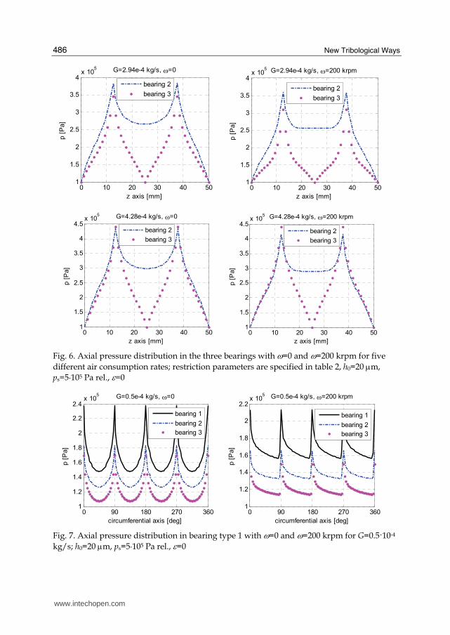
New Tribological Ways
486
0 10 20 30 40 501
15
2
25
3
35
4x 10
5 G=294e-4 kgs ω=0
z axis [mm]
p [
Pa]
bearing 2
bearing 3
0 10 20 30 40 501
15
2
25
3
35
4x 10
5 G=294e-4 kgs ω=200 krpm
z axis [mm]
p [
Pa]
bearing 2
bearing 3
0 10 20 30 40 501
15
2
25
3
35
4
45x 10
5 G=428e-4 kgs ω=0
z axis [mm]
p [
Pa]
bearing 2
bearing 3
0 10 20 30 40 501
15
2
25
3
35
4
45x 10
5 G=428e-4 kgs ω=200 krpm
z axis [mm]
p [
Pa]
bearing 2
bearing 3
Fig 6 Axial pressure distribution in the three bearings with ω=0 and ω=200 krpm for five
different air consumption rates restriction parameters are specified in table 2 h0=20 μm
ps=5middot105 Pa rel ε=0
0 90 180 270 3601
12
14
16
18
2
22
24x 10
5 G=05e-4 kgs ω=0
circumferential axis [deg]
p [
Pa]
bearing 1
bearing 2
bearing 3
0 90 180 270 3601
12
14
16
18
2
22x 10
5 G=05e-4 kgs ω=200 krpm
circumferential axis [deg]
p [
Pa]
bearing 1
bearing 2
bearing 3
Fig 7 Axial pressure distribution in bearing type 1 with ω=0 and ω=200 krpm for G=0510-4
kgs h0=20 μm ps=5middot105 Pa rel ε=0
wwwintechopencom
Comparison between Different Supply Port Configurations in Gas Journal Bearings
487
is shown in figure 9 vs Λ for the three bearings considering different restriction parameters
Figure 9 also shows steady-state attitude angle β calculated as follows
1tan xy
xx
k
kβ minus= (12)
Fig 8 Bearing reaction force on the journal in steady-state conditions due to shaft displacement along direction x
Stiffness increased with Λ up to saturation (Λgt100) At G=0510-4 kgs bearing type 1 was
found to be stiffer than the other two regardless of Λ but at higher air consumption bearing
type 2 exhibited greater stiffness at low speeds (Λlt9) With the three bearings in sonic conditions (G=0510-4 kgs) stiffness trends do not intersect and their difference was almost constant When bearing type 1 approached saturation (pc 0 ps) its stiffness at low speed dropped (see case with G=14210-4 kgs) This happened
also for bearing type 2 but at greater air consumptions Stiffness at high speeds (Λgt100) always increased with G At G=42810-4 kgs stiffness at low speeds for bearing types 2 and 3 coincided at very low values due to saturation of bearings
The attitude angle with increasing Λ also increased from zero to a maximum and then returned to zero The extent of maximum depended on the difference between bearing
stiffness at low and high speeds where this difference was high also maximum β was high
Table 3 shows ratio k(Λgt100)k(Λ=0) for the three bearings to highlight this relationship
45 Rotor trajectories
The whirl motion of the perfectly balanced rotor during rotation is represented in figure 10 The motion can be stable or unstable In the former case the rotor is attracted toward the centre of the bushing after initial disturbance in the latter case the bearing forces move the rotor away from central position
wwwintechopencom
New Tribological Ways
488
bearing type k(Λgt100)k(Λ=0) air flow G104 [kgs]
1 262
2 271
3 375
05
1 254
2 182
3 24
142
1 58
2 2
3 22
214
2 25
3 226 294
2 533 3 308
428
Table 3 Ratio k(Λgt100)k(Λ=0) for the three bearings given different air consumptions G
10-1
100
101
102
0
05
1
15
2
25G=05e-4 kgs
Λ
k
bearing 1
bearing 2
bearing 3
10-1
100
101
102
-40
-30
-20
-10
0G=05e-4 kgs
Λ
β [deg]
bearing 1
bearing 2
bearing 3
10-1
100
101
102
05
1
15
2
25
3G=142e-4 kgs
Λ
k
bearing 1
bearing 2
bearing 3
10-1
100
101
102
-25
-20
-15
-10
-5
0G=142e-4 kgs
Λ
β [deg]
bearing 1
bearing 2
bearing 3
wwwintechopencom
Comparison between Different Supply Port Configurations in Gas Journal Bearings
489
10-1
100
101
102
05
1
15
2
25
3
35
4G=214e-4 kgs
Λ
k
bearing 1
bearing 2
bearing 3
10-1
100
101
102
-50
-40
-30
-20
-10
0G=214e-4 kgs
Λβ [d
eg]
bearing 1
bearing 2
bearing 3
10-1
100
101
102
05
1
15
2
25
3
35G=294e-4 kgs
Λ
k
bearing 2
bearing 3
10-1
100
101
102
-25
-20
-15
-10
-5
0G=294e-4 kgs
Λ
β [deg]
bearing 2
bearing 3
10-1
100
101
102
0
1
2
3
4
5G=428e-4 kgs
Λ
k
bearing 2
bearing 3
10-1
100
101
102
-40
-30
-20
-10
0G=428e-4 kgs
Λ
β [deg]
bearing 2
bearing 3
Fig 9 Non-dimensional bearing stiffness k and attitude angle β vs bearing number Λ for the three bearings
wwwintechopencom
New Tribological Ways
490
The initial condition used in the following curves are specified by
( ) ( )0 005 0 0x yε ε= =
( ) ( ) ( )0 0 0 0 xxkx y x
m= =$ $
Initial tangential speed was imposed on the rotor to produce a centrifugal force equal to the
static radial force This particular condition was adopted to decrease the simulation time
required to distinguish stability from instability In fact with a different initial condition on
y$ the trajectory would have been less circular necessitating simulation of a longer
transient Stability decreased with increasing rotor mass m figure 10 shows a comparison of
rotor trajectories obtained for the same initial condition but at different values of m The
rotor-bearing system became unstable when the dynamic attitude angle turned negative as
shown in figure 11 In the stable condition the rotor angular moment calculated relative to
the centre of the bushing decreased with time In unstable conditions the mechanical work
done by bearing forces was found to be positive and the rotor angular moment increased
(see figure 11b) The curves in figure 11 help distinguish stable versus unstable conditions
as resulting when compared to figure 10
-2 -1 0 1 2
x 10-6
-2
-15
-1
-05
0
05
1
15
2x 10
-6
xg [m]
yg [
m]
m=9 kg
m=95 kg
m=11 kg
Fig 10 Rotor trajectories with different rotor masses and initial condition x(0)=1 μm
dydt(0)=x(0)(kxxm)^(05) ω=20 krpm bearing type 1
wwwintechopencom
Comparison between Different Supply Port Configurations in Gas Journal Bearings
491
0 0005 001 0015 002-25
-20
-15
-10
-5
0
5
10
t [s]
att
itude a
ngle
β [deg]
m=9 kg
m=95 kg
m=11 kg
0 0005 001 0015 00205
1
15
2
25
3x 10
-8
t [s]
angula
r m
om
ent
[kgm
2s
]
m=9 kg
m=95 kg
m=11 kg
(a) (b)
Fig 11 Attitude angle vs time (a) and rotor angular moment vs time (b) with different
rotor masses and initial condition x(0)=1 μm dydt(0)=x(0)(kxxm)^(05) ω=20 krpm bearing type 1
The three bearings are compared in figures 12 and 13 showing the rotor trajectories for identical initial condition the attitude angle vs time and the rotor angular moment vs time In this case bearing types 1 and 2 are very similar while bearing type 3 is unstable
-3 -2 -1 0 1 2 3 4-3
-2
-1
0
1
2
3
xg [μm]
yg [
μm]
bearing 1
bearing 2
bearing 3
Fig 12 Rotor trajectories with the three bearing types m=1 kg ω=50 krpm initial conditions
x(0)=1 μm and dydt(0)=x(0)(kxxm)^(05)
wwwintechopencom
New Tribological Ways
492
0 2 4 6
x 10-3
-40
-20
0
20
40
60
80
t [s]
att
itude a
ngle
[deg]
bearing 1
bearing 2
bearing 3
1 2 3 4 5
x 10-3
0
05
1
15
2
25
x 10-8
t [s]
angula
r m
om
ent
[kgm
2s
]
bearing 1
bearing 2
bearing 3
(a) (b)
Fig 13 Attitude angle vs time a) and rotor angular moment vs time b) for the three bearing
types m=1 kg ω=50 krpm initial conditions x(0)=1 μm and dydt(0)=x(0)(kxxm)^(05)
46 Bearing damping factor
Stiffness and damping coefficients of gas bearings are known to depend on bearing number Λ and also on whirl frequency ν Stability may also be evaluated through the equivalent damping factor calculated by identifying the system with a second-order differential equation having constant coefficients
0mx cx kx+ + =$ $ (13)
The damping factor is expressed by
2
c
kmζ = (14)
and the radial coordinate of the journal centre is
( )0 ntr r e ζωminus= (15)
where the natural frequency is
n
k
mω = (16)
The journal motion is stable when described by a spiral which decreases with time In this
case ζ is positive When the damping factor is negative the spiral increases with time
Figure 14 shows damping factor ζ vs m for G=0510-4 kgs In this case bearing type 3 exhibited lower damping capacity than the other bearings
47 Whirl ratio
The shaft whirl frequency vs m is shown in figure 15 for G=0510-4 kgs The whirl
frequency decreases with m and increases with ω The rotor mass at stability threshold is
wwwintechopencom
Comparison between Different Supply Port Configurations in Gas Journal Bearings
493
10-1
100
101
102
-015
-01
-005
0
005
01
015
02
m [kg]
ζ
bearing 1 20 krpm
bearing 1 50 krpm
bearing 1 100 krpm
bearing 1 200 krpm
bearing 2 20 krpm
bearing 2 50 krpm
bearing 2 100 krpm
bearing 2 200 krpm
bearing 3 20 krpm
bearing 3 50 krpm
bearing 3 100 krpm
bearing 3 200 krpm
Fig 14 Damping factor vs rotor mass at different rotating speeds G=0510-4 kgs
10-1
100
101
104
105
m [kg]
ν [rpm
]
bearing 1 20 krpm
bearing 1 50 krpm
bearing 1 100 krpm
bearing 1 200 krpm
bearing 2 20 krpm
bearing 2 50 krpm
bearing 2 100 krpm
bearing 2 200 krpm
bearing 3 20 krpm
bearing 3 50 krpm
bearing 3 100 krpm
bearing 3 200 krpm
Fig 15 Whirl frequency ν vs m at different rotating speeds G=0510-4 kgs
wwwintechopencom
New Tribological Ways
494
05 1 15 204
045
05
055
mmth
γ
20 krpm
50 krpm
100 krpm
200 krpm
Fig 16 Whirl ratio γ vs mmth at different speeds bearing type 1 G=0510-4 kgs
indicated as mth Figure 16 shows whirl ratio γ vs ratio mmth At the stability threshold it is slightly lower than 05 and decreases with shaft mass m
48 Stability threshold
Figure 17 shows rotor mass m vs bearing number Λ at the stability threshold for the three bearings On logarithmic axes the curves are linear and may be expressed by
( )10 10 0 10 10 0log log log logm m αminus = Λ minus Λ (17)
where m0 and Λ0 refer to a reference condition Angular coefficient α is -2 approx From this equation we obtain the following relation
0 0
m
m
α⎛ ⎞Λ= ⎜ ⎟Λ⎝ ⎠ (18)
The stability thresholds with different inherence parameters were found to be similar but translated to different mass values
49 Comparison of bearing types at different restriction parameters
Figure 18 shows the trends of bearing stiffness vs G for ω=0 rpm and ω=200 krpm and figure 19 shows critical journal mass mth vs G The order of preference of the bearings changes when different air consumption rates are considered If stiffness at low bearing numbers is the most important parameter bearing type 1 is the best option only for Gle05104 kgs in other cases bearing type 2 is to be preferred If it is important to maximize the bearing stiffness at high bearing numbers bearing type is to be chosen Considering the stability threshold bearing type 2 is the best one for Ggt05104 kgs while for Gle05104 kgs bearing 1 is to be preferred
wwwintechopencom
Comparison between Different Supply Port Configurations in Gas Journal Bearings
495
101
10-2
10-1
100
101
102
Λ
mth
[kg]
bearing 1 G=05e-4 kgs
bearing 2 G=05e-4 kgs
bearing 3 G=05e-4 kgs
bearing 1 G=142e-4 kgs
bearing 2 G=142e-4 kgs
bearing 3 G=142e-4 kgs
Fig 17 Rotor mass m at stability threshold vs bearing number Λ for the three bearings
0 2 4 6
x 10-4
02
04
06
08
1
12
14
16ω=0 krpm
air consumption [kgs]
k
bearing 1
bearing 2
bearing 3
0 2 4 6
x 10-4
1
15
2
25
3
35
4ω=200 krpm
air consumption [kgs]
k
bearing 1
bearing 2
bearing 3
a) b)
Fig 18 Bearing stiffness k vs air consumption for the three bearings a) ω=0 rpm b) ω=200 krpm
wwwintechopencom
New Tribological Ways
496
05 1 15 2 25 3 35 4 45
x 10-4
004
006
008
01
012
014
016
018
02
022
024
air consumption [kgs]
mth
bearing 1
bearing 2
bearing 3
Fig 19 Rotor mass at stability threshold vs air consumption for the three bearings
5 Conclusion
Three bearing types were compared for different restriction parameters Bearing type 1 featured four supply ports situated in the bearing centre plane Bearing type 2 featured two sets of supply ports situated at z=L4 and z=3L4 Bearing type 3 also featured a central vented circumferential chamber The following conclusions were drawn
bull bearing type 2 in general is to be preferred to the other bearing types because of the higher stiffness and stability threshold at equal air consumption
bull with increasing Λ the attitude angle went from zero to max subsequently returning to zero max value was proportional to the difference between bearing stiffness at low and at high speeds
bull at the stability threshold the whirl ratio was slightly lower than 05
bull the curve of mth vs Λ on the logarithmic axes was linear and with changing restriction parameters the shaft critical mass changed by a factor regardless of speed
6 List of symbols
D bearing diameter F bearing force on journal G air mass flow rate L bearing axial length Rs pneumatic resistance of the supply hole Rh pneumatic resistance of clearance R0 gas constant in calculations R0=2876 m2s2K Re Reynolds number T0 absolute temperature in calculations T0=288 K
wwwintechopencom
Comparison between Different Supply Port Configurations in Gas Journal Bearings
497
b ratio of critical pressure to admission pressure b=0528 c damping coefficient cd supply hole discharge coefficient h local air clearance h0 clearance with rotor in centred position k bearing radial stiffness k non-dimensional bearing radial stiffness m rotor mass mth rotor mass at stability threshold nm number of nodes along axial and circumferential directions xyz cartesian coordinates pa ambient pressure pc supply hole downstream pressure ps bearing supply pressure
rθz cylindrical coordinates t time Λ bearing number Λ=6mωpa(D2h0)2 β steady attitude angle γ whirl ratio γ =νω ε eccentricity ratio μ dynamic viscosity in calculations μ=178910-6 Pas ν whirl frequency ζ bearing damping factor ω rotor angular speed
7 References
Andres LS (1990) Approximate analysis of turbulent hybrid bearings static and dynamic performance for centered operation ASME Journal of Tribology Vol 112 692-698
Belforte G Raparelli T Viktorov V (1999) Theoretical investigation of fluid inertia effects and stability of self-acting gas journal bearings ASME Journal of Tribology Vol 121 836-843
Belforte G Raparelli T Viktorov V Trivella A (2008) Discharge coefficients of orifice-type restrictor for aerostatic bearings Tribology International Vol 40 512-521
Cheng HS Pan CHT (1965) Stability analysis of gas-lubricated self-acting plain cylindrical journal bearings of finite length using Galerkinrsquos method ASME Journal of Basic Engineering 185-192
Colombo F Raparelli T Viktorov V (2009) Externally pressurized gas bearings a comparison between two supply holes configurations Tribology International Vol 42 303-310
Gross WA Zachmanaglou EC (1961) Perturbation solutions for Gas lubricating films Trans ASME Journal of Basic Engineering Vol 83 139-144
Han DC Park SS Kim WJ KimJW (1994) A study on the characteristics of externally pressurized gas bearings Precision Engineering Vol 16 No 3 164-173
Heller S Shapiro W Decker O (1971) A porous hydrostatic gas bearing for use in miniature turbomachinery ASLE Transactions 144-155
wwwintechopencom
New Tribological Ways
498
Lund JW (1968) Calculation of stiffness and damping properties of gas bearings ASME Journal of Lubrication Technology 793-803
Sawicki JT Capaldi RJ Adams ML (1997) Experimental and theoretical rotordynamic characteristics of a hybrid journal bearing ASME Journal of Tribology Vol 119 132-141
Su JCT Lie KN (2003) Rotation effects on hybrid air journal bearings Tribology International Vol 36 717-726
Su JCT Lie KN (2006) Rotor dynamic instability analysis on hybrid air journal bearings Tribology International Vol 39 No 1 238-248
Sun DC (1975) Stability of gas-lubricated externally pressurized porous journal bearings ASME Journal of Lubrication Technology 494-505
Wadhwa SS Sinhasant R Singh DV (1983) Analysis of orifice compensated externally pressurized gas bearing Tribology International Vol 16 No 4 203-211
Yang DW Chen CH Kang Y Hwang RM Shyr SS (2009) Influence of orifices on stability of rotor-aerostatic bearing system Tribology International Vol 42 1206-1219
Yoshikawa H Ota T Higashino K Nakai S (1999) Numerical analysis on dynamic characteristics of cryogenic hydrostatic journal bearing ASME Journal of Tribology Vol 121 879-885
Zhang RQ Chang HS (1995) A new type of hydrostatichydrodynamic gas journal bearing and its optimization for maximum stability Tribology Transactions Vol 38 No 3 589-594
wwwintechopencom
New Tribological WaysEdited by Dr Taher Ghrib
ISBN 978-953-307-206-7Hard cover 498 pagesPublisher InTechPublished online 26 April 2011Published in print edition April 2011
InTech EuropeUniversity Campus STeP Ri Slavka Krautzeka 83A 51000 Rijeka Croatia Phone +385 (51) 770 447 Fax +385 (51) 686 166wwwintechopencom
InTech ChinaUnit 405 Office Block Hotel Equatorial Shanghai No65 Yan An Road (West) Shanghai 200040 China
Phone +86-21-62489820 Fax +86-21-62489821
This book aims to recapitulate old informations available and brings new informations that are with the fashionresearch on an atomic and nanometric scale in various fields by introducing several mathematical models tomeasure some parameters characterizing metals like the hydrodynamic elasticity coefficient hardnesslubricant viscosity viscosity coefficient tensile strength It uses new measurement techniques verydeveloped and nondestructive Its principal distinctions of the other books that it brings practical manners tomodel and to optimize the cutting process using various parameters and different techniques namely usingwater of high-velocity stream tool with different form and radius the cutting temperature effect that can bemeasured with sufficient accuracy not only at a research lab and also with a theoretical forecast This bookaspire to minimize and eliminate the losses resulting from surfaces friction and wear which leads to a greatermachining efficiency and to a better execution fewer breakdowns and a significant saving A great part isdevoted to lubrication of which the goal is to find the famous techniques using solid and liquid lubricant filmsapplied for giving super low friction coefficients and improving the lubricant properties on surfaces
How to referenceIn order to correctly reference this scholarly work feel free to copy and paste the following
Federico Colombo Terenziano Raparelli and Vladimir Viktorov (2011) Comparison between Different SupplyPort Configurations in Gas Journal Bearings New Tribological Ways Dr Taher Ghrib (Ed) ISBN 978-953-307-206-7 InTech Available from httpwwwintechopencombooksnew-tribological-wayscomparison-between-different-supply-port-configurations-in-gas-journal-bearings
copy 2011 The Author(s) Licensee IntechOpen This chapter is distributedunder the terms of the Creative Commons Attribution-NonCommercial-ShareAlike-30 License which permits use distribution and reproduction fornon-commercial purposes provided the original is properly cited andderivative works building on this content are distributed under the samelicense

Comparison between Different Supply Port Configurations in Gas Journal Bearings
487
is shown in figure 9 vs Λ for the three bearings considering different restriction parameters
Figure 9 also shows steady-state attitude angle β calculated as follows
1tan xy
xx
k
kβ minus= (12)
Fig 8 Bearing reaction force on the journal in steady-state conditions due to shaft displacement along direction x
Stiffness increased with Λ up to saturation (Λgt100) At G=0510-4 kgs bearing type 1 was
found to be stiffer than the other two regardless of Λ but at higher air consumption bearing
type 2 exhibited greater stiffness at low speeds (Λlt9) With the three bearings in sonic conditions (G=0510-4 kgs) stiffness trends do not intersect and their difference was almost constant When bearing type 1 approached saturation (pc 0 ps) its stiffness at low speed dropped (see case with G=14210-4 kgs) This happened
also for bearing type 2 but at greater air consumptions Stiffness at high speeds (Λgt100) always increased with G At G=42810-4 kgs stiffness at low speeds for bearing types 2 and 3 coincided at very low values due to saturation of bearings
The attitude angle with increasing Λ also increased from zero to a maximum and then returned to zero The extent of maximum depended on the difference between bearing
stiffness at low and high speeds where this difference was high also maximum β was high
Table 3 shows ratio k(Λgt100)k(Λ=0) for the three bearings to highlight this relationship
45 Rotor trajectories
The whirl motion of the perfectly balanced rotor during rotation is represented in figure 10 The motion can be stable or unstable In the former case the rotor is attracted toward the centre of the bushing after initial disturbance in the latter case the bearing forces move the rotor away from central position
wwwintechopencom
New Tribological Ways
488
bearing type k(Λgt100)k(Λ=0) air flow G104 [kgs]
1 262
2 271
3 375
05
1 254
2 182
3 24
142
1 58
2 2
3 22
214
2 25
3 226 294
2 533 3 308
428
Table 3 Ratio k(Λgt100)k(Λ=0) for the three bearings given different air consumptions G
10-1
100
101
102
0
05
1
15
2
25G=05e-4 kgs
Λ
k
bearing 1
bearing 2
bearing 3
10-1
100
101
102
-40
-30
-20
-10
0G=05e-4 kgs
Λ
β [deg]
bearing 1
bearing 2
bearing 3
10-1
100
101
102
05
1
15
2
25
3G=142e-4 kgs
Λ
k
bearing 1
bearing 2
bearing 3
10-1
100
101
102
-25
-20
-15
-10
-5
0G=142e-4 kgs
Λ
β [deg]
bearing 1
bearing 2
bearing 3
wwwintechopencom
Comparison between Different Supply Port Configurations in Gas Journal Bearings
489
10-1
100
101
102
05
1
15
2
25
3
35
4G=214e-4 kgs
Λ
k
bearing 1
bearing 2
bearing 3
10-1
100
101
102
-50
-40
-30
-20
-10
0G=214e-4 kgs
Λβ [d
eg]
bearing 1
bearing 2
bearing 3
10-1
100
101
102
05
1
15
2
25
3
35G=294e-4 kgs
Λ
k
bearing 2
bearing 3
10-1
100
101
102
-25
-20
-15
-10
-5
0G=294e-4 kgs
Λ
β [deg]
bearing 2
bearing 3
10-1
100
101
102
0
1
2
3
4
5G=428e-4 kgs
Λ
k
bearing 2
bearing 3
10-1
100
101
102
-40
-30
-20
-10
0G=428e-4 kgs
Λ
β [deg]
bearing 2
bearing 3
Fig 9 Non-dimensional bearing stiffness k and attitude angle β vs bearing number Λ for the three bearings
wwwintechopencom
New Tribological Ways
490
The initial condition used in the following curves are specified by
( ) ( )0 005 0 0x yε ε= =
( ) ( ) ( )0 0 0 0 xxkx y x
m= =$ $
Initial tangential speed was imposed on the rotor to produce a centrifugal force equal to the
static radial force This particular condition was adopted to decrease the simulation time
required to distinguish stability from instability In fact with a different initial condition on
y$ the trajectory would have been less circular necessitating simulation of a longer
transient Stability decreased with increasing rotor mass m figure 10 shows a comparison of
rotor trajectories obtained for the same initial condition but at different values of m The
rotor-bearing system became unstable when the dynamic attitude angle turned negative as
shown in figure 11 In the stable condition the rotor angular moment calculated relative to
the centre of the bushing decreased with time In unstable conditions the mechanical work
done by bearing forces was found to be positive and the rotor angular moment increased
(see figure 11b) The curves in figure 11 help distinguish stable versus unstable conditions
as resulting when compared to figure 10
-2 -1 0 1 2
x 10-6
-2
-15
-1
-05
0
05
1
15
2x 10
-6
xg [m]
yg [
m]
m=9 kg
m=95 kg
m=11 kg
Fig 10 Rotor trajectories with different rotor masses and initial condition x(0)=1 μm
dydt(0)=x(0)(kxxm)^(05) ω=20 krpm bearing type 1
wwwintechopencom
Comparison between Different Supply Port Configurations in Gas Journal Bearings
491
0 0005 001 0015 002-25
-20
-15
-10
-5
0
5
10
t [s]
att
itude a
ngle
β [deg]
m=9 kg
m=95 kg
m=11 kg
0 0005 001 0015 00205
1
15
2
25
3x 10
-8
t [s]
angula
r m
om
ent
[kgm
2s
]
m=9 kg
m=95 kg
m=11 kg
(a) (b)
Fig 11 Attitude angle vs time (a) and rotor angular moment vs time (b) with different
rotor masses and initial condition x(0)=1 μm dydt(0)=x(0)(kxxm)^(05) ω=20 krpm bearing type 1
The three bearings are compared in figures 12 and 13 showing the rotor trajectories for identical initial condition the attitude angle vs time and the rotor angular moment vs time In this case bearing types 1 and 2 are very similar while bearing type 3 is unstable
-3 -2 -1 0 1 2 3 4-3
-2
-1
0
1
2
3
xg [μm]
yg [
μm]
bearing 1
bearing 2
bearing 3
Fig 12 Rotor trajectories with the three bearing types m=1 kg ω=50 krpm initial conditions
x(0)=1 μm and dydt(0)=x(0)(kxxm)^(05)
wwwintechopencom
New Tribological Ways
492
0 2 4 6
x 10-3
-40
-20
0
20
40
60
80
t [s]
att
itude a
ngle
[deg]
bearing 1
bearing 2
bearing 3
1 2 3 4 5
x 10-3
0
05
1
15
2
25
x 10-8
t [s]
angula
r m
om
ent
[kgm
2s
]
bearing 1
bearing 2
bearing 3
(a) (b)
Fig 13 Attitude angle vs time a) and rotor angular moment vs time b) for the three bearing
types m=1 kg ω=50 krpm initial conditions x(0)=1 μm and dydt(0)=x(0)(kxxm)^(05)
46 Bearing damping factor
Stiffness and damping coefficients of gas bearings are known to depend on bearing number Λ and also on whirl frequency ν Stability may also be evaluated through the equivalent damping factor calculated by identifying the system with a second-order differential equation having constant coefficients
0mx cx kx+ + =$ $ (13)
The damping factor is expressed by
2
c
kmζ = (14)
and the radial coordinate of the journal centre is
( )0 ntr r e ζωminus= (15)
where the natural frequency is
n
k
mω = (16)
The journal motion is stable when described by a spiral which decreases with time In this
case ζ is positive When the damping factor is negative the spiral increases with time
Figure 14 shows damping factor ζ vs m for G=0510-4 kgs In this case bearing type 3 exhibited lower damping capacity than the other bearings
47 Whirl ratio
The shaft whirl frequency vs m is shown in figure 15 for G=0510-4 kgs The whirl
frequency decreases with m and increases with ω The rotor mass at stability threshold is
wwwintechopencom
Comparison between Different Supply Port Configurations in Gas Journal Bearings
493
10-1
100
101
102
-015
-01
-005
0
005
01
015
02
m [kg]
ζ
bearing 1 20 krpm
bearing 1 50 krpm
bearing 1 100 krpm
bearing 1 200 krpm
bearing 2 20 krpm
bearing 2 50 krpm
bearing 2 100 krpm
bearing 2 200 krpm
bearing 3 20 krpm
bearing 3 50 krpm
bearing 3 100 krpm
bearing 3 200 krpm
Fig 14 Damping factor vs rotor mass at different rotating speeds G=0510-4 kgs
10-1
100
101
104
105
m [kg]
ν [rpm
]
bearing 1 20 krpm
bearing 1 50 krpm
bearing 1 100 krpm
bearing 1 200 krpm
bearing 2 20 krpm
bearing 2 50 krpm
bearing 2 100 krpm
bearing 2 200 krpm
bearing 3 20 krpm
bearing 3 50 krpm
bearing 3 100 krpm
bearing 3 200 krpm
Fig 15 Whirl frequency ν vs m at different rotating speeds G=0510-4 kgs
wwwintechopencom
New Tribological Ways
494
05 1 15 204
045
05
055
mmth
γ
20 krpm
50 krpm
100 krpm
200 krpm
Fig 16 Whirl ratio γ vs mmth at different speeds bearing type 1 G=0510-4 kgs
indicated as mth Figure 16 shows whirl ratio γ vs ratio mmth At the stability threshold it is slightly lower than 05 and decreases with shaft mass m
48 Stability threshold
Figure 17 shows rotor mass m vs bearing number Λ at the stability threshold for the three bearings On logarithmic axes the curves are linear and may be expressed by
( )10 10 0 10 10 0log log log logm m αminus = Λ minus Λ (17)
where m0 and Λ0 refer to a reference condition Angular coefficient α is -2 approx From this equation we obtain the following relation
0 0
m
m
α⎛ ⎞Λ= ⎜ ⎟Λ⎝ ⎠ (18)
The stability thresholds with different inherence parameters were found to be similar but translated to different mass values
49 Comparison of bearing types at different restriction parameters
Figure 18 shows the trends of bearing stiffness vs G for ω=0 rpm and ω=200 krpm and figure 19 shows critical journal mass mth vs G The order of preference of the bearings changes when different air consumption rates are considered If stiffness at low bearing numbers is the most important parameter bearing type 1 is the best option only for Gle05104 kgs in other cases bearing type 2 is to be preferred If it is important to maximize the bearing stiffness at high bearing numbers bearing type is to be chosen Considering the stability threshold bearing type 2 is the best one for Ggt05104 kgs while for Gle05104 kgs bearing 1 is to be preferred
wwwintechopencom
Comparison between Different Supply Port Configurations in Gas Journal Bearings
495
101
10-2
10-1
100
101
102
Λ
mth
[kg]
bearing 1 G=05e-4 kgs
bearing 2 G=05e-4 kgs
bearing 3 G=05e-4 kgs
bearing 1 G=142e-4 kgs
bearing 2 G=142e-4 kgs
bearing 3 G=142e-4 kgs
Fig 17 Rotor mass m at stability threshold vs bearing number Λ for the three bearings
0 2 4 6
x 10-4
02
04
06
08
1
12
14
16ω=0 krpm
air consumption [kgs]
k
bearing 1
bearing 2
bearing 3
0 2 4 6
x 10-4
1
15
2
25
3
35
4ω=200 krpm
air consumption [kgs]
k
bearing 1
bearing 2
bearing 3
a) b)
Fig 18 Bearing stiffness k vs air consumption for the three bearings a) ω=0 rpm b) ω=200 krpm
wwwintechopencom
New Tribological Ways
496
05 1 15 2 25 3 35 4 45
x 10-4
004
006
008
01
012
014
016
018
02
022
024
air consumption [kgs]
mth
bearing 1
bearing 2
bearing 3
Fig 19 Rotor mass at stability threshold vs air consumption for the three bearings
5 Conclusion
Three bearing types were compared for different restriction parameters Bearing type 1 featured four supply ports situated in the bearing centre plane Bearing type 2 featured two sets of supply ports situated at z=L4 and z=3L4 Bearing type 3 also featured a central vented circumferential chamber The following conclusions were drawn
bull bearing type 2 in general is to be preferred to the other bearing types because of the higher stiffness and stability threshold at equal air consumption
bull with increasing Λ the attitude angle went from zero to max subsequently returning to zero max value was proportional to the difference between bearing stiffness at low and at high speeds
bull at the stability threshold the whirl ratio was slightly lower than 05
bull the curve of mth vs Λ on the logarithmic axes was linear and with changing restriction parameters the shaft critical mass changed by a factor regardless of speed
6 List of symbols
D bearing diameter F bearing force on journal G air mass flow rate L bearing axial length Rs pneumatic resistance of the supply hole Rh pneumatic resistance of clearance R0 gas constant in calculations R0=2876 m2s2K Re Reynolds number T0 absolute temperature in calculations T0=288 K
wwwintechopencom
Comparison between Different Supply Port Configurations in Gas Journal Bearings
497
b ratio of critical pressure to admission pressure b=0528 c damping coefficient cd supply hole discharge coefficient h local air clearance h0 clearance with rotor in centred position k bearing radial stiffness k non-dimensional bearing radial stiffness m rotor mass mth rotor mass at stability threshold nm number of nodes along axial and circumferential directions xyz cartesian coordinates pa ambient pressure pc supply hole downstream pressure ps bearing supply pressure
rθz cylindrical coordinates t time Λ bearing number Λ=6mωpa(D2h0)2 β steady attitude angle γ whirl ratio γ =νω ε eccentricity ratio μ dynamic viscosity in calculations μ=178910-6 Pas ν whirl frequency ζ bearing damping factor ω rotor angular speed
7 References
Andres LS (1990) Approximate analysis of turbulent hybrid bearings static and dynamic performance for centered operation ASME Journal of Tribology Vol 112 692-698
Belforte G Raparelli T Viktorov V (1999) Theoretical investigation of fluid inertia effects and stability of self-acting gas journal bearings ASME Journal of Tribology Vol 121 836-843
Belforte G Raparelli T Viktorov V Trivella A (2008) Discharge coefficients of orifice-type restrictor for aerostatic bearings Tribology International Vol 40 512-521
Cheng HS Pan CHT (1965) Stability analysis of gas-lubricated self-acting plain cylindrical journal bearings of finite length using Galerkinrsquos method ASME Journal of Basic Engineering 185-192
Colombo F Raparelli T Viktorov V (2009) Externally pressurized gas bearings a comparison between two supply holes configurations Tribology International Vol 42 303-310
Gross WA Zachmanaglou EC (1961) Perturbation solutions for Gas lubricating films Trans ASME Journal of Basic Engineering Vol 83 139-144
Han DC Park SS Kim WJ KimJW (1994) A study on the characteristics of externally pressurized gas bearings Precision Engineering Vol 16 No 3 164-173
Heller S Shapiro W Decker O (1971) A porous hydrostatic gas bearing for use in miniature turbomachinery ASLE Transactions 144-155
wwwintechopencom
New Tribological Ways
498
Lund JW (1968) Calculation of stiffness and damping properties of gas bearings ASME Journal of Lubrication Technology 793-803
Sawicki JT Capaldi RJ Adams ML (1997) Experimental and theoretical rotordynamic characteristics of a hybrid journal bearing ASME Journal of Tribology Vol 119 132-141
Su JCT Lie KN (2003) Rotation effects on hybrid air journal bearings Tribology International Vol 36 717-726
Su JCT Lie KN (2006) Rotor dynamic instability analysis on hybrid air journal bearings Tribology International Vol 39 No 1 238-248
Sun DC (1975) Stability of gas-lubricated externally pressurized porous journal bearings ASME Journal of Lubrication Technology 494-505
Wadhwa SS Sinhasant R Singh DV (1983) Analysis of orifice compensated externally pressurized gas bearing Tribology International Vol 16 No 4 203-211
Yang DW Chen CH Kang Y Hwang RM Shyr SS (2009) Influence of orifices on stability of rotor-aerostatic bearing system Tribology International Vol 42 1206-1219
Yoshikawa H Ota T Higashino K Nakai S (1999) Numerical analysis on dynamic characteristics of cryogenic hydrostatic journal bearing ASME Journal of Tribology Vol 121 879-885
Zhang RQ Chang HS (1995) A new type of hydrostatichydrodynamic gas journal bearing and its optimization for maximum stability Tribology Transactions Vol 38 No 3 589-594
wwwintechopencom
New Tribological WaysEdited by Dr Taher Ghrib
ISBN 978-953-307-206-7Hard cover 498 pagesPublisher InTechPublished online 26 April 2011Published in print edition April 2011
InTech EuropeUniversity Campus STeP Ri Slavka Krautzeka 83A 51000 Rijeka Croatia Phone +385 (51) 770 447 Fax +385 (51) 686 166wwwintechopencom
InTech ChinaUnit 405 Office Block Hotel Equatorial Shanghai No65 Yan An Road (West) Shanghai 200040 China
Phone +86-21-62489820 Fax +86-21-62489821
This book aims to recapitulate old informations available and brings new informations that are with the fashionresearch on an atomic and nanometric scale in various fields by introducing several mathematical models tomeasure some parameters characterizing metals like the hydrodynamic elasticity coefficient hardnesslubricant viscosity viscosity coefficient tensile strength It uses new measurement techniques verydeveloped and nondestructive Its principal distinctions of the other books that it brings practical manners tomodel and to optimize the cutting process using various parameters and different techniques namely usingwater of high-velocity stream tool with different form and radius the cutting temperature effect that can bemeasured with sufficient accuracy not only at a research lab and also with a theoretical forecast This bookaspire to minimize and eliminate the losses resulting from surfaces friction and wear which leads to a greatermachining efficiency and to a better execution fewer breakdowns and a significant saving A great part isdevoted to lubrication of which the goal is to find the famous techniques using solid and liquid lubricant filmsapplied for giving super low friction coefficients and improving the lubricant properties on surfaces
How to referenceIn order to correctly reference this scholarly work feel free to copy and paste the following
Federico Colombo Terenziano Raparelli and Vladimir Viktorov (2011) Comparison between Different SupplyPort Configurations in Gas Journal Bearings New Tribological Ways Dr Taher Ghrib (Ed) ISBN 978-953-307-206-7 InTech Available from httpwwwintechopencombooksnew-tribological-wayscomparison-between-different-supply-port-configurations-in-gas-journal-bearings
copy 2011 The Author(s) Licensee IntechOpen This chapter is distributedunder the terms of the Creative Commons Attribution-NonCommercial-ShareAlike-30 License which permits use distribution and reproduction fornon-commercial purposes provided the original is properly cited andderivative works building on this content are distributed under the samelicense

New Tribological Ways
488
bearing type k(Λgt100)k(Λ=0) air flow G104 [kgs]
1 262
2 271
3 375
05
1 254
2 182
3 24
142
1 58
2 2
3 22
214
2 25
3 226 294
2 533 3 308
428
Table 3 Ratio k(Λgt100)k(Λ=0) for the three bearings given different air consumptions G
10-1
100
101
102
0
05
1
15
2
25G=05e-4 kgs
Λ
k
bearing 1
bearing 2
bearing 3
10-1
100
101
102
-40
-30
-20
-10
0G=05e-4 kgs
Λ
β [deg]
bearing 1
bearing 2
bearing 3
10-1
100
101
102
05
1
15
2
25
3G=142e-4 kgs
Λ
k
bearing 1
bearing 2
bearing 3
10-1
100
101
102
-25
-20
-15
-10
-5
0G=142e-4 kgs
Λ
β [deg]
bearing 1
bearing 2
bearing 3
wwwintechopencom
Comparison between Different Supply Port Configurations in Gas Journal Bearings
489
10-1
100
101
102
05
1
15
2
25
3
35
4G=214e-4 kgs
Λ
k
bearing 1
bearing 2
bearing 3
10-1
100
101
102
-50
-40
-30
-20
-10
0G=214e-4 kgs
Λβ [d
eg]
bearing 1
bearing 2
bearing 3
10-1
100
101
102
05
1
15
2
25
3
35G=294e-4 kgs
Λ
k
bearing 2
bearing 3
10-1
100
101
102
-25
-20
-15
-10
-5
0G=294e-4 kgs
Λ
β [deg]
bearing 2
bearing 3
10-1
100
101
102
0
1
2
3
4
5G=428e-4 kgs
Λ
k
bearing 2
bearing 3
10-1
100
101
102
-40
-30
-20
-10
0G=428e-4 kgs
Λ
β [deg]
bearing 2
bearing 3
Fig 9 Non-dimensional bearing stiffness k and attitude angle β vs bearing number Λ for the three bearings
wwwintechopencom
New Tribological Ways
490
The initial condition used in the following curves are specified by
( ) ( )0 005 0 0x yε ε= =
( ) ( ) ( )0 0 0 0 xxkx y x
m= =$ $
Initial tangential speed was imposed on the rotor to produce a centrifugal force equal to the
static radial force This particular condition was adopted to decrease the simulation time
required to distinguish stability from instability In fact with a different initial condition on
y$ the trajectory would have been less circular necessitating simulation of a longer
transient Stability decreased with increasing rotor mass m figure 10 shows a comparison of
rotor trajectories obtained for the same initial condition but at different values of m The
rotor-bearing system became unstable when the dynamic attitude angle turned negative as
shown in figure 11 In the stable condition the rotor angular moment calculated relative to
the centre of the bushing decreased with time In unstable conditions the mechanical work
done by bearing forces was found to be positive and the rotor angular moment increased
(see figure 11b) The curves in figure 11 help distinguish stable versus unstable conditions
as resulting when compared to figure 10
-2 -1 0 1 2
x 10-6
-2
-15
-1
-05
0
05
1
15
2x 10
-6
xg [m]
yg [
m]
m=9 kg
m=95 kg
m=11 kg
Fig 10 Rotor trajectories with different rotor masses and initial condition x(0)=1 μm
dydt(0)=x(0)(kxxm)^(05) ω=20 krpm bearing type 1
wwwintechopencom
Comparison between Different Supply Port Configurations in Gas Journal Bearings
491
0 0005 001 0015 002-25
-20
-15
-10
-5
0
5
10
t [s]
att
itude a
ngle
β [deg]
m=9 kg
m=95 kg
m=11 kg
0 0005 001 0015 00205
1
15
2
25
3x 10
-8
t [s]
angula
r m
om
ent
[kgm
2s
]
m=9 kg
m=95 kg
m=11 kg
(a) (b)
Fig 11 Attitude angle vs time (a) and rotor angular moment vs time (b) with different
rotor masses and initial condition x(0)=1 μm dydt(0)=x(0)(kxxm)^(05) ω=20 krpm bearing type 1
The three bearings are compared in figures 12 and 13 showing the rotor trajectories for identical initial condition the attitude angle vs time and the rotor angular moment vs time In this case bearing types 1 and 2 are very similar while bearing type 3 is unstable
-3 -2 -1 0 1 2 3 4-3
-2
-1
0
1
2
3
xg [μm]
yg [
μm]
bearing 1
bearing 2
bearing 3
Fig 12 Rotor trajectories with the three bearing types m=1 kg ω=50 krpm initial conditions
x(0)=1 μm and dydt(0)=x(0)(kxxm)^(05)
wwwintechopencom
New Tribological Ways
492
0 2 4 6
x 10-3
-40
-20
0
20
40
60
80
t [s]
att
itude a
ngle
[deg]
bearing 1
bearing 2
bearing 3
1 2 3 4 5
x 10-3
0
05
1
15
2
25
x 10-8
t [s]
angula
r m
om
ent
[kgm
2s
]
bearing 1
bearing 2
bearing 3
(a) (b)
Fig 13 Attitude angle vs time a) and rotor angular moment vs time b) for the three bearing
types m=1 kg ω=50 krpm initial conditions x(0)=1 μm and dydt(0)=x(0)(kxxm)^(05)
46 Bearing damping factor
Stiffness and damping coefficients of gas bearings are known to depend on bearing number Λ and also on whirl frequency ν Stability may also be evaluated through the equivalent damping factor calculated by identifying the system with a second-order differential equation having constant coefficients
0mx cx kx+ + =$ $ (13)
The damping factor is expressed by
2
c
kmζ = (14)
and the radial coordinate of the journal centre is
( )0 ntr r e ζωminus= (15)
where the natural frequency is
n
k
mω = (16)
The journal motion is stable when described by a spiral which decreases with time In this
case ζ is positive When the damping factor is negative the spiral increases with time
Figure 14 shows damping factor ζ vs m for G=0510-4 kgs In this case bearing type 3 exhibited lower damping capacity than the other bearings
47 Whirl ratio
The shaft whirl frequency vs m is shown in figure 15 for G=0510-4 kgs The whirl
frequency decreases with m and increases with ω The rotor mass at stability threshold is
wwwintechopencom
Comparison between Different Supply Port Configurations in Gas Journal Bearings
493
10-1
100
101
102
-015
-01
-005
0
005
01
015
02
m [kg]
ζ
bearing 1 20 krpm
bearing 1 50 krpm
bearing 1 100 krpm
bearing 1 200 krpm
bearing 2 20 krpm
bearing 2 50 krpm
bearing 2 100 krpm
bearing 2 200 krpm
bearing 3 20 krpm
bearing 3 50 krpm
bearing 3 100 krpm
bearing 3 200 krpm
Fig 14 Damping factor vs rotor mass at different rotating speeds G=0510-4 kgs
10-1
100
101
104
105
m [kg]
ν [rpm
]
bearing 1 20 krpm
bearing 1 50 krpm
bearing 1 100 krpm
bearing 1 200 krpm
bearing 2 20 krpm
bearing 2 50 krpm
bearing 2 100 krpm
bearing 2 200 krpm
bearing 3 20 krpm
bearing 3 50 krpm
bearing 3 100 krpm
bearing 3 200 krpm
Fig 15 Whirl frequency ν vs m at different rotating speeds G=0510-4 kgs
wwwintechopencom
New Tribological Ways
494
05 1 15 204
045
05
055
mmth
γ
20 krpm
50 krpm
100 krpm
200 krpm
Fig 16 Whirl ratio γ vs mmth at different speeds bearing type 1 G=0510-4 kgs
indicated as mth Figure 16 shows whirl ratio γ vs ratio mmth At the stability threshold it is slightly lower than 05 and decreases with shaft mass m
48 Stability threshold
Figure 17 shows rotor mass m vs bearing number Λ at the stability threshold for the three bearings On logarithmic axes the curves are linear and may be expressed by
( )10 10 0 10 10 0log log log logm m αminus = Λ minus Λ (17)
where m0 and Λ0 refer to a reference condition Angular coefficient α is -2 approx From this equation we obtain the following relation
0 0
m
m
α⎛ ⎞Λ= ⎜ ⎟Λ⎝ ⎠ (18)
The stability thresholds with different inherence parameters were found to be similar but translated to different mass values
49 Comparison of bearing types at different restriction parameters
Figure 18 shows the trends of bearing stiffness vs G for ω=0 rpm and ω=200 krpm and figure 19 shows critical journal mass mth vs G The order of preference of the bearings changes when different air consumption rates are considered If stiffness at low bearing numbers is the most important parameter bearing type 1 is the best option only for Gle05104 kgs in other cases bearing type 2 is to be preferred If it is important to maximize the bearing stiffness at high bearing numbers bearing type is to be chosen Considering the stability threshold bearing type 2 is the best one for Ggt05104 kgs while for Gle05104 kgs bearing 1 is to be preferred
wwwintechopencom
Comparison between Different Supply Port Configurations in Gas Journal Bearings
495
101
10-2
10-1
100
101
102
Λ
mth
[kg]
bearing 1 G=05e-4 kgs
bearing 2 G=05e-4 kgs
bearing 3 G=05e-4 kgs
bearing 1 G=142e-4 kgs
bearing 2 G=142e-4 kgs
bearing 3 G=142e-4 kgs
Fig 17 Rotor mass m at stability threshold vs bearing number Λ for the three bearings
0 2 4 6
x 10-4
02
04
06
08
1
12
14
16ω=0 krpm
air consumption [kgs]
k
bearing 1
bearing 2
bearing 3
0 2 4 6
x 10-4
1
15
2
25
3
35
4ω=200 krpm
air consumption [kgs]
k
bearing 1
bearing 2
bearing 3
a) b)
Fig 18 Bearing stiffness k vs air consumption for the three bearings a) ω=0 rpm b) ω=200 krpm
wwwintechopencom
New Tribological Ways
496
05 1 15 2 25 3 35 4 45
x 10-4
004
006
008
01
012
014
016
018
02
022
024
air consumption [kgs]
mth
bearing 1
bearing 2
bearing 3
Fig 19 Rotor mass at stability threshold vs air consumption for the three bearings
5 Conclusion
Three bearing types were compared for different restriction parameters Bearing type 1 featured four supply ports situated in the bearing centre plane Bearing type 2 featured two sets of supply ports situated at z=L4 and z=3L4 Bearing type 3 also featured a central vented circumferential chamber The following conclusions were drawn
bull bearing type 2 in general is to be preferred to the other bearing types because of the higher stiffness and stability threshold at equal air consumption
bull with increasing Λ the attitude angle went from zero to max subsequently returning to zero max value was proportional to the difference between bearing stiffness at low and at high speeds
bull at the stability threshold the whirl ratio was slightly lower than 05
bull the curve of mth vs Λ on the logarithmic axes was linear and with changing restriction parameters the shaft critical mass changed by a factor regardless of speed
6 List of symbols
D bearing diameter F bearing force on journal G air mass flow rate L bearing axial length Rs pneumatic resistance of the supply hole Rh pneumatic resistance of clearance R0 gas constant in calculations R0=2876 m2s2K Re Reynolds number T0 absolute temperature in calculations T0=288 K
wwwintechopencom
Comparison between Different Supply Port Configurations in Gas Journal Bearings
497
b ratio of critical pressure to admission pressure b=0528 c damping coefficient cd supply hole discharge coefficient h local air clearance h0 clearance with rotor in centred position k bearing radial stiffness k non-dimensional bearing radial stiffness m rotor mass mth rotor mass at stability threshold nm number of nodes along axial and circumferential directions xyz cartesian coordinates pa ambient pressure pc supply hole downstream pressure ps bearing supply pressure
rθz cylindrical coordinates t time Λ bearing number Λ=6mωpa(D2h0)2 β steady attitude angle γ whirl ratio γ =νω ε eccentricity ratio μ dynamic viscosity in calculations μ=178910-6 Pas ν whirl frequency ζ bearing damping factor ω rotor angular speed
7 References
Andres LS (1990) Approximate analysis of turbulent hybrid bearings static and dynamic performance for centered operation ASME Journal of Tribology Vol 112 692-698
Belforte G Raparelli T Viktorov V (1999) Theoretical investigation of fluid inertia effects and stability of self-acting gas journal bearings ASME Journal of Tribology Vol 121 836-843
Belforte G Raparelli T Viktorov V Trivella A (2008) Discharge coefficients of orifice-type restrictor for aerostatic bearings Tribology International Vol 40 512-521
Cheng HS Pan CHT (1965) Stability analysis of gas-lubricated self-acting plain cylindrical journal bearings of finite length using Galerkinrsquos method ASME Journal of Basic Engineering 185-192
Colombo F Raparelli T Viktorov V (2009) Externally pressurized gas bearings a comparison between two supply holes configurations Tribology International Vol 42 303-310
Gross WA Zachmanaglou EC (1961) Perturbation solutions for Gas lubricating films Trans ASME Journal of Basic Engineering Vol 83 139-144
Han DC Park SS Kim WJ KimJW (1994) A study on the characteristics of externally pressurized gas bearings Precision Engineering Vol 16 No 3 164-173
Heller S Shapiro W Decker O (1971) A porous hydrostatic gas bearing for use in miniature turbomachinery ASLE Transactions 144-155
wwwintechopencom
New Tribological Ways
498
Lund JW (1968) Calculation of stiffness and damping properties of gas bearings ASME Journal of Lubrication Technology 793-803
Sawicki JT Capaldi RJ Adams ML (1997) Experimental and theoretical rotordynamic characteristics of a hybrid journal bearing ASME Journal of Tribology Vol 119 132-141
Su JCT Lie KN (2003) Rotation effects on hybrid air journal bearings Tribology International Vol 36 717-726
Su JCT Lie KN (2006) Rotor dynamic instability analysis on hybrid air journal bearings Tribology International Vol 39 No 1 238-248
Sun DC (1975) Stability of gas-lubricated externally pressurized porous journal bearings ASME Journal of Lubrication Technology 494-505
Wadhwa SS Sinhasant R Singh DV (1983) Analysis of orifice compensated externally pressurized gas bearing Tribology International Vol 16 No 4 203-211
Yang DW Chen CH Kang Y Hwang RM Shyr SS (2009) Influence of orifices on stability of rotor-aerostatic bearing system Tribology International Vol 42 1206-1219
Yoshikawa H Ota T Higashino K Nakai S (1999) Numerical analysis on dynamic characteristics of cryogenic hydrostatic journal bearing ASME Journal of Tribology Vol 121 879-885
Zhang RQ Chang HS (1995) A new type of hydrostatichydrodynamic gas journal bearing and its optimization for maximum stability Tribology Transactions Vol 38 No 3 589-594
wwwintechopencom
New Tribological WaysEdited by Dr Taher Ghrib
ISBN 978-953-307-206-7Hard cover 498 pagesPublisher InTechPublished online 26 April 2011Published in print edition April 2011
InTech EuropeUniversity Campus STeP Ri Slavka Krautzeka 83A 51000 Rijeka Croatia Phone +385 (51) 770 447 Fax +385 (51) 686 166wwwintechopencom
InTech ChinaUnit 405 Office Block Hotel Equatorial Shanghai No65 Yan An Road (West) Shanghai 200040 China
Phone +86-21-62489820 Fax +86-21-62489821
This book aims to recapitulate old informations available and brings new informations that are with the fashionresearch on an atomic and nanometric scale in various fields by introducing several mathematical models tomeasure some parameters characterizing metals like the hydrodynamic elasticity coefficient hardnesslubricant viscosity viscosity coefficient tensile strength It uses new measurement techniques verydeveloped and nondestructive Its principal distinctions of the other books that it brings practical manners tomodel and to optimize the cutting process using various parameters and different techniques namely usingwater of high-velocity stream tool with different form and radius the cutting temperature effect that can bemeasured with sufficient accuracy not only at a research lab and also with a theoretical forecast This bookaspire to minimize and eliminate the losses resulting from surfaces friction and wear which leads to a greatermachining efficiency and to a better execution fewer breakdowns and a significant saving A great part isdevoted to lubrication of which the goal is to find the famous techniques using solid and liquid lubricant filmsapplied for giving super low friction coefficients and improving the lubricant properties on surfaces
How to referenceIn order to correctly reference this scholarly work feel free to copy and paste the following
Federico Colombo Terenziano Raparelli and Vladimir Viktorov (2011) Comparison between Different SupplyPort Configurations in Gas Journal Bearings New Tribological Ways Dr Taher Ghrib (Ed) ISBN 978-953-307-206-7 InTech Available from httpwwwintechopencombooksnew-tribological-wayscomparison-between-different-supply-port-configurations-in-gas-journal-bearings
copy 2011 The Author(s) Licensee IntechOpen This chapter is distributedunder the terms of the Creative Commons Attribution-NonCommercial-ShareAlike-30 License which permits use distribution and reproduction fornon-commercial purposes provided the original is properly cited andderivative works building on this content are distributed under the samelicense

Comparison between Different Supply Port Configurations in Gas Journal Bearings
489
10-1
100
101
102
05
1
15
2
25
3
35
4G=214e-4 kgs
Λ
k
bearing 1
bearing 2
bearing 3
10-1
100
101
102
-50
-40
-30
-20
-10
0G=214e-4 kgs
Λβ [d
eg]
bearing 1
bearing 2
bearing 3
10-1
100
101
102
05
1
15
2
25
3
35G=294e-4 kgs
Λ
k
bearing 2
bearing 3
10-1
100
101
102
-25
-20
-15
-10
-5
0G=294e-4 kgs
Λ
β [deg]
bearing 2
bearing 3
10-1
100
101
102
0
1
2
3
4
5G=428e-4 kgs
Λ
k
bearing 2
bearing 3
10-1
100
101
102
-40
-30
-20
-10
0G=428e-4 kgs
Λ
β [deg]
bearing 2
bearing 3
Fig 9 Non-dimensional bearing stiffness k and attitude angle β vs bearing number Λ for the three bearings
wwwintechopencom
New Tribological Ways
490
The initial condition used in the following curves are specified by
( ) ( )0 005 0 0x yε ε= =
( ) ( ) ( )0 0 0 0 xxkx y x
m= =$ $
Initial tangential speed was imposed on the rotor to produce a centrifugal force equal to the
static radial force This particular condition was adopted to decrease the simulation time
required to distinguish stability from instability In fact with a different initial condition on
y$ the trajectory would have been less circular necessitating simulation of a longer
transient Stability decreased with increasing rotor mass m figure 10 shows a comparison of
rotor trajectories obtained for the same initial condition but at different values of m The
rotor-bearing system became unstable when the dynamic attitude angle turned negative as
shown in figure 11 In the stable condition the rotor angular moment calculated relative to
the centre of the bushing decreased with time In unstable conditions the mechanical work
done by bearing forces was found to be positive and the rotor angular moment increased
(see figure 11b) The curves in figure 11 help distinguish stable versus unstable conditions
as resulting when compared to figure 10
-2 -1 0 1 2
x 10-6
-2
-15
-1
-05
0
05
1
15
2x 10
-6
xg [m]
yg [
m]
m=9 kg
m=95 kg
m=11 kg
Fig 10 Rotor trajectories with different rotor masses and initial condition x(0)=1 μm
dydt(0)=x(0)(kxxm)^(05) ω=20 krpm bearing type 1
wwwintechopencom
Comparison between Different Supply Port Configurations in Gas Journal Bearings
491
0 0005 001 0015 002-25
-20
-15
-10
-5
0
5
10
t [s]
att
itude a
ngle
β [deg]
m=9 kg
m=95 kg
m=11 kg
0 0005 001 0015 00205
1
15
2
25
3x 10
-8
t [s]
angula
r m
om
ent
[kgm
2s
]
m=9 kg
m=95 kg
m=11 kg
(a) (b)
Fig 11 Attitude angle vs time (a) and rotor angular moment vs time (b) with different
rotor masses and initial condition x(0)=1 μm dydt(0)=x(0)(kxxm)^(05) ω=20 krpm bearing type 1
The three bearings are compared in figures 12 and 13 showing the rotor trajectories for identical initial condition the attitude angle vs time and the rotor angular moment vs time In this case bearing types 1 and 2 are very similar while bearing type 3 is unstable
-3 -2 -1 0 1 2 3 4-3
-2
-1
0
1
2
3
xg [μm]
yg [
μm]
bearing 1
bearing 2
bearing 3
Fig 12 Rotor trajectories with the three bearing types m=1 kg ω=50 krpm initial conditions
x(0)=1 μm and dydt(0)=x(0)(kxxm)^(05)
wwwintechopencom
New Tribological Ways
492
0 2 4 6
x 10-3
-40
-20
0
20
40
60
80
t [s]
att
itude a
ngle
[deg]
bearing 1
bearing 2
bearing 3
1 2 3 4 5
x 10-3
0
05
1
15
2
25
x 10-8
t [s]
angula
r m
om
ent
[kgm
2s
]
bearing 1
bearing 2
bearing 3
(a) (b)
Fig 13 Attitude angle vs time a) and rotor angular moment vs time b) for the three bearing
types m=1 kg ω=50 krpm initial conditions x(0)=1 μm and dydt(0)=x(0)(kxxm)^(05)
46 Bearing damping factor
Stiffness and damping coefficients of gas bearings are known to depend on bearing number Λ and also on whirl frequency ν Stability may also be evaluated through the equivalent damping factor calculated by identifying the system with a second-order differential equation having constant coefficients
0mx cx kx+ + =$ $ (13)
The damping factor is expressed by
2
c
kmζ = (14)
and the radial coordinate of the journal centre is
( )0 ntr r e ζωminus= (15)
where the natural frequency is
n
k
mω = (16)
The journal motion is stable when described by a spiral which decreases with time In this
case ζ is positive When the damping factor is negative the spiral increases with time
Figure 14 shows damping factor ζ vs m for G=0510-4 kgs In this case bearing type 3 exhibited lower damping capacity than the other bearings
47 Whirl ratio
The shaft whirl frequency vs m is shown in figure 15 for G=0510-4 kgs The whirl
frequency decreases with m and increases with ω The rotor mass at stability threshold is
wwwintechopencom
Comparison between Different Supply Port Configurations in Gas Journal Bearings
493
10-1
100
101
102
-015
-01
-005
0
005
01
015
02
m [kg]
ζ
bearing 1 20 krpm
bearing 1 50 krpm
bearing 1 100 krpm
bearing 1 200 krpm
bearing 2 20 krpm
bearing 2 50 krpm
bearing 2 100 krpm
bearing 2 200 krpm
bearing 3 20 krpm
bearing 3 50 krpm
bearing 3 100 krpm
bearing 3 200 krpm
Fig 14 Damping factor vs rotor mass at different rotating speeds G=0510-4 kgs
10-1
100
101
104
105
m [kg]
ν [rpm
]
bearing 1 20 krpm
bearing 1 50 krpm
bearing 1 100 krpm
bearing 1 200 krpm
bearing 2 20 krpm
bearing 2 50 krpm
bearing 2 100 krpm
bearing 2 200 krpm
bearing 3 20 krpm
bearing 3 50 krpm
bearing 3 100 krpm
bearing 3 200 krpm
Fig 15 Whirl frequency ν vs m at different rotating speeds G=0510-4 kgs
wwwintechopencom
New Tribological Ways
494
05 1 15 204
045
05
055
mmth
γ
20 krpm
50 krpm
100 krpm
200 krpm
Fig 16 Whirl ratio γ vs mmth at different speeds bearing type 1 G=0510-4 kgs
indicated as mth Figure 16 shows whirl ratio γ vs ratio mmth At the stability threshold it is slightly lower than 05 and decreases with shaft mass m
48 Stability threshold
Figure 17 shows rotor mass m vs bearing number Λ at the stability threshold for the three bearings On logarithmic axes the curves are linear and may be expressed by
( )10 10 0 10 10 0log log log logm m αminus = Λ minus Λ (17)
where m0 and Λ0 refer to a reference condition Angular coefficient α is -2 approx From this equation we obtain the following relation
0 0
m
m
α⎛ ⎞Λ= ⎜ ⎟Λ⎝ ⎠ (18)
The stability thresholds with different inherence parameters were found to be similar but translated to different mass values
49 Comparison of bearing types at different restriction parameters
Figure 18 shows the trends of bearing stiffness vs G for ω=0 rpm and ω=200 krpm and figure 19 shows critical journal mass mth vs G The order of preference of the bearings changes when different air consumption rates are considered If stiffness at low bearing numbers is the most important parameter bearing type 1 is the best option only for Gle05104 kgs in other cases bearing type 2 is to be preferred If it is important to maximize the bearing stiffness at high bearing numbers bearing type is to be chosen Considering the stability threshold bearing type 2 is the best one for Ggt05104 kgs while for Gle05104 kgs bearing 1 is to be preferred
wwwintechopencom
Comparison between Different Supply Port Configurations in Gas Journal Bearings
495
101
10-2
10-1
100
101
102
Λ
mth
[kg]
bearing 1 G=05e-4 kgs
bearing 2 G=05e-4 kgs
bearing 3 G=05e-4 kgs
bearing 1 G=142e-4 kgs
bearing 2 G=142e-4 kgs
bearing 3 G=142e-4 kgs
Fig 17 Rotor mass m at stability threshold vs bearing number Λ for the three bearings
0 2 4 6
x 10-4
02
04
06
08
1
12
14
16ω=0 krpm
air consumption [kgs]
k
bearing 1
bearing 2
bearing 3
0 2 4 6
x 10-4
1
15
2
25
3
35
4ω=200 krpm
air consumption [kgs]
k
bearing 1
bearing 2
bearing 3
a) b)
Fig 18 Bearing stiffness k vs air consumption for the three bearings a) ω=0 rpm b) ω=200 krpm
wwwintechopencom
New Tribological Ways
496
05 1 15 2 25 3 35 4 45
x 10-4
004
006
008
01
012
014
016
018
02
022
024
air consumption [kgs]
mth
bearing 1
bearing 2
bearing 3
Fig 19 Rotor mass at stability threshold vs air consumption for the three bearings
5 Conclusion
Three bearing types were compared for different restriction parameters Bearing type 1 featured four supply ports situated in the bearing centre plane Bearing type 2 featured two sets of supply ports situated at z=L4 and z=3L4 Bearing type 3 also featured a central vented circumferential chamber The following conclusions were drawn
bull bearing type 2 in general is to be preferred to the other bearing types because of the higher stiffness and stability threshold at equal air consumption
bull with increasing Λ the attitude angle went from zero to max subsequently returning to zero max value was proportional to the difference between bearing stiffness at low and at high speeds
bull at the stability threshold the whirl ratio was slightly lower than 05
bull the curve of mth vs Λ on the logarithmic axes was linear and with changing restriction parameters the shaft critical mass changed by a factor regardless of speed
6 List of symbols
D bearing diameter F bearing force on journal G air mass flow rate L bearing axial length Rs pneumatic resistance of the supply hole Rh pneumatic resistance of clearance R0 gas constant in calculations R0=2876 m2s2K Re Reynolds number T0 absolute temperature in calculations T0=288 K
wwwintechopencom
Comparison between Different Supply Port Configurations in Gas Journal Bearings
497
b ratio of critical pressure to admission pressure b=0528 c damping coefficient cd supply hole discharge coefficient h local air clearance h0 clearance with rotor in centred position k bearing radial stiffness k non-dimensional bearing radial stiffness m rotor mass mth rotor mass at stability threshold nm number of nodes along axial and circumferential directions xyz cartesian coordinates pa ambient pressure pc supply hole downstream pressure ps bearing supply pressure
rθz cylindrical coordinates t time Λ bearing number Λ=6mωpa(D2h0)2 β steady attitude angle γ whirl ratio γ =νω ε eccentricity ratio μ dynamic viscosity in calculations μ=178910-6 Pas ν whirl frequency ζ bearing damping factor ω rotor angular speed
7 References
Andres LS (1990) Approximate analysis of turbulent hybrid bearings static and dynamic performance for centered operation ASME Journal of Tribology Vol 112 692-698
Belforte G Raparelli T Viktorov V (1999) Theoretical investigation of fluid inertia effects and stability of self-acting gas journal bearings ASME Journal of Tribology Vol 121 836-843
Belforte G Raparelli T Viktorov V Trivella A (2008) Discharge coefficients of orifice-type restrictor for aerostatic bearings Tribology International Vol 40 512-521
Cheng HS Pan CHT (1965) Stability analysis of gas-lubricated self-acting plain cylindrical journal bearings of finite length using Galerkinrsquos method ASME Journal of Basic Engineering 185-192
Colombo F Raparelli T Viktorov V (2009) Externally pressurized gas bearings a comparison between two supply holes configurations Tribology International Vol 42 303-310
Gross WA Zachmanaglou EC (1961) Perturbation solutions for Gas lubricating films Trans ASME Journal of Basic Engineering Vol 83 139-144
Han DC Park SS Kim WJ KimJW (1994) A study on the characteristics of externally pressurized gas bearings Precision Engineering Vol 16 No 3 164-173
Heller S Shapiro W Decker O (1971) A porous hydrostatic gas bearing for use in miniature turbomachinery ASLE Transactions 144-155
wwwintechopencom
New Tribological Ways
498
Lund JW (1968) Calculation of stiffness and damping properties of gas bearings ASME Journal of Lubrication Technology 793-803
Sawicki JT Capaldi RJ Adams ML (1997) Experimental and theoretical rotordynamic characteristics of a hybrid journal bearing ASME Journal of Tribology Vol 119 132-141
Su JCT Lie KN (2003) Rotation effects on hybrid air journal bearings Tribology International Vol 36 717-726
Su JCT Lie KN (2006) Rotor dynamic instability analysis on hybrid air journal bearings Tribology International Vol 39 No 1 238-248
Sun DC (1975) Stability of gas-lubricated externally pressurized porous journal bearings ASME Journal of Lubrication Technology 494-505
Wadhwa SS Sinhasant R Singh DV (1983) Analysis of orifice compensated externally pressurized gas bearing Tribology International Vol 16 No 4 203-211
Yang DW Chen CH Kang Y Hwang RM Shyr SS (2009) Influence of orifices on stability of rotor-aerostatic bearing system Tribology International Vol 42 1206-1219
Yoshikawa H Ota T Higashino K Nakai S (1999) Numerical analysis on dynamic characteristics of cryogenic hydrostatic journal bearing ASME Journal of Tribology Vol 121 879-885
Zhang RQ Chang HS (1995) A new type of hydrostatichydrodynamic gas journal bearing and its optimization for maximum stability Tribology Transactions Vol 38 No 3 589-594
wwwintechopencom
New Tribological WaysEdited by Dr Taher Ghrib
ISBN 978-953-307-206-7Hard cover 498 pagesPublisher InTechPublished online 26 April 2011Published in print edition April 2011
InTech EuropeUniversity Campus STeP Ri Slavka Krautzeka 83A 51000 Rijeka Croatia Phone +385 (51) 770 447 Fax +385 (51) 686 166wwwintechopencom
InTech ChinaUnit 405 Office Block Hotel Equatorial Shanghai No65 Yan An Road (West) Shanghai 200040 China
Phone +86-21-62489820 Fax +86-21-62489821
This book aims to recapitulate old informations available and brings new informations that are with the fashionresearch on an atomic and nanometric scale in various fields by introducing several mathematical models tomeasure some parameters characterizing metals like the hydrodynamic elasticity coefficient hardnesslubricant viscosity viscosity coefficient tensile strength It uses new measurement techniques verydeveloped and nondestructive Its principal distinctions of the other books that it brings practical manners tomodel and to optimize the cutting process using various parameters and different techniques namely usingwater of high-velocity stream tool with different form and radius the cutting temperature effect that can bemeasured with sufficient accuracy not only at a research lab and also with a theoretical forecast This bookaspire to minimize and eliminate the losses resulting from surfaces friction and wear which leads to a greatermachining efficiency and to a better execution fewer breakdowns and a significant saving A great part isdevoted to lubrication of which the goal is to find the famous techniques using solid and liquid lubricant filmsapplied for giving super low friction coefficients and improving the lubricant properties on surfaces
How to referenceIn order to correctly reference this scholarly work feel free to copy and paste the following
Federico Colombo Terenziano Raparelli and Vladimir Viktorov (2011) Comparison between Different SupplyPort Configurations in Gas Journal Bearings New Tribological Ways Dr Taher Ghrib (Ed) ISBN 978-953-307-206-7 InTech Available from httpwwwintechopencombooksnew-tribological-wayscomparison-between-different-supply-port-configurations-in-gas-journal-bearings
copy 2011 The Author(s) Licensee IntechOpen This chapter is distributedunder the terms of the Creative Commons Attribution-NonCommercial-ShareAlike-30 License which permits use distribution and reproduction fornon-commercial purposes provided the original is properly cited andderivative works building on this content are distributed under the samelicense
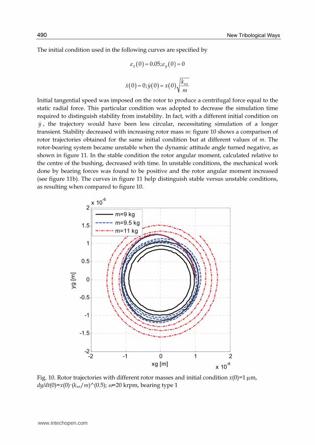
New Tribological Ways
490
The initial condition used in the following curves are specified by
( ) ( )0 005 0 0x yε ε= =
( ) ( ) ( )0 0 0 0 xxkx y x
m= =$ $
Initial tangential speed was imposed on the rotor to produce a centrifugal force equal to the
static radial force This particular condition was adopted to decrease the simulation time
required to distinguish stability from instability In fact with a different initial condition on
y$ the trajectory would have been less circular necessitating simulation of a longer
transient Stability decreased with increasing rotor mass m figure 10 shows a comparison of
rotor trajectories obtained for the same initial condition but at different values of m The
rotor-bearing system became unstable when the dynamic attitude angle turned negative as
shown in figure 11 In the stable condition the rotor angular moment calculated relative to
the centre of the bushing decreased with time In unstable conditions the mechanical work
done by bearing forces was found to be positive and the rotor angular moment increased
(see figure 11b) The curves in figure 11 help distinguish stable versus unstable conditions
as resulting when compared to figure 10
-2 -1 0 1 2
x 10-6
-2
-15
-1
-05
0
05
1
15
2x 10
-6
xg [m]
yg [
m]
m=9 kg
m=95 kg
m=11 kg
Fig 10 Rotor trajectories with different rotor masses and initial condition x(0)=1 μm
dydt(0)=x(0)(kxxm)^(05) ω=20 krpm bearing type 1
wwwintechopencom
Comparison between Different Supply Port Configurations in Gas Journal Bearings
491
0 0005 001 0015 002-25
-20
-15
-10
-5
0
5
10
t [s]
att
itude a
ngle
β [deg]
m=9 kg
m=95 kg
m=11 kg
0 0005 001 0015 00205
1
15
2
25
3x 10
-8
t [s]
angula
r m
om
ent
[kgm
2s
]
m=9 kg
m=95 kg
m=11 kg
(a) (b)
Fig 11 Attitude angle vs time (a) and rotor angular moment vs time (b) with different
rotor masses and initial condition x(0)=1 μm dydt(0)=x(0)(kxxm)^(05) ω=20 krpm bearing type 1
The three bearings are compared in figures 12 and 13 showing the rotor trajectories for identical initial condition the attitude angle vs time and the rotor angular moment vs time In this case bearing types 1 and 2 are very similar while bearing type 3 is unstable
-3 -2 -1 0 1 2 3 4-3
-2
-1
0
1
2
3
xg [μm]
yg [
μm]
bearing 1
bearing 2
bearing 3
Fig 12 Rotor trajectories with the three bearing types m=1 kg ω=50 krpm initial conditions
x(0)=1 μm and dydt(0)=x(0)(kxxm)^(05)
wwwintechopencom
New Tribological Ways
492
0 2 4 6
x 10-3
-40
-20
0
20
40
60
80
t [s]
att
itude a
ngle
[deg]
bearing 1
bearing 2
bearing 3
1 2 3 4 5
x 10-3
0
05
1
15
2
25
x 10-8
t [s]
angula
r m
om
ent
[kgm
2s
]
bearing 1
bearing 2
bearing 3
(a) (b)
Fig 13 Attitude angle vs time a) and rotor angular moment vs time b) for the three bearing
types m=1 kg ω=50 krpm initial conditions x(0)=1 μm and dydt(0)=x(0)(kxxm)^(05)
46 Bearing damping factor
Stiffness and damping coefficients of gas bearings are known to depend on bearing number Λ and also on whirl frequency ν Stability may also be evaluated through the equivalent damping factor calculated by identifying the system with a second-order differential equation having constant coefficients
0mx cx kx+ + =$ $ (13)
The damping factor is expressed by
2
c
kmζ = (14)
and the radial coordinate of the journal centre is
( )0 ntr r e ζωminus= (15)
where the natural frequency is
n
k
mω = (16)
The journal motion is stable when described by a spiral which decreases with time In this
case ζ is positive When the damping factor is negative the spiral increases with time
Figure 14 shows damping factor ζ vs m for G=0510-4 kgs In this case bearing type 3 exhibited lower damping capacity than the other bearings
47 Whirl ratio
The shaft whirl frequency vs m is shown in figure 15 for G=0510-4 kgs The whirl
frequency decreases with m and increases with ω The rotor mass at stability threshold is
wwwintechopencom
Comparison between Different Supply Port Configurations in Gas Journal Bearings
493
10-1
100
101
102
-015
-01
-005
0
005
01
015
02
m [kg]
ζ
bearing 1 20 krpm
bearing 1 50 krpm
bearing 1 100 krpm
bearing 1 200 krpm
bearing 2 20 krpm
bearing 2 50 krpm
bearing 2 100 krpm
bearing 2 200 krpm
bearing 3 20 krpm
bearing 3 50 krpm
bearing 3 100 krpm
bearing 3 200 krpm
Fig 14 Damping factor vs rotor mass at different rotating speeds G=0510-4 kgs
10-1
100
101
104
105
m [kg]
ν [rpm
]
bearing 1 20 krpm
bearing 1 50 krpm
bearing 1 100 krpm
bearing 1 200 krpm
bearing 2 20 krpm
bearing 2 50 krpm
bearing 2 100 krpm
bearing 2 200 krpm
bearing 3 20 krpm
bearing 3 50 krpm
bearing 3 100 krpm
bearing 3 200 krpm
Fig 15 Whirl frequency ν vs m at different rotating speeds G=0510-4 kgs
wwwintechopencom
New Tribological Ways
494
05 1 15 204
045
05
055
mmth
γ
20 krpm
50 krpm
100 krpm
200 krpm
Fig 16 Whirl ratio γ vs mmth at different speeds bearing type 1 G=0510-4 kgs
indicated as mth Figure 16 shows whirl ratio γ vs ratio mmth At the stability threshold it is slightly lower than 05 and decreases with shaft mass m
48 Stability threshold
Figure 17 shows rotor mass m vs bearing number Λ at the stability threshold for the three bearings On logarithmic axes the curves are linear and may be expressed by
( )10 10 0 10 10 0log log log logm m αminus = Λ minus Λ (17)
where m0 and Λ0 refer to a reference condition Angular coefficient α is -2 approx From this equation we obtain the following relation
0 0
m
m
α⎛ ⎞Λ= ⎜ ⎟Λ⎝ ⎠ (18)
The stability thresholds with different inherence parameters were found to be similar but translated to different mass values
49 Comparison of bearing types at different restriction parameters
Figure 18 shows the trends of bearing stiffness vs G for ω=0 rpm and ω=200 krpm and figure 19 shows critical journal mass mth vs G The order of preference of the bearings changes when different air consumption rates are considered If stiffness at low bearing numbers is the most important parameter bearing type 1 is the best option only for Gle05104 kgs in other cases bearing type 2 is to be preferred If it is important to maximize the bearing stiffness at high bearing numbers bearing type is to be chosen Considering the stability threshold bearing type 2 is the best one for Ggt05104 kgs while for Gle05104 kgs bearing 1 is to be preferred
wwwintechopencom
Comparison between Different Supply Port Configurations in Gas Journal Bearings
495
101
10-2
10-1
100
101
102
Λ
mth
[kg]
bearing 1 G=05e-4 kgs
bearing 2 G=05e-4 kgs
bearing 3 G=05e-4 kgs
bearing 1 G=142e-4 kgs
bearing 2 G=142e-4 kgs
bearing 3 G=142e-4 kgs
Fig 17 Rotor mass m at stability threshold vs bearing number Λ for the three bearings
0 2 4 6
x 10-4
02
04
06
08
1
12
14
16ω=0 krpm
air consumption [kgs]
k
bearing 1
bearing 2
bearing 3
0 2 4 6
x 10-4
1
15
2
25
3
35
4ω=200 krpm
air consumption [kgs]
k
bearing 1
bearing 2
bearing 3
a) b)
Fig 18 Bearing stiffness k vs air consumption for the three bearings a) ω=0 rpm b) ω=200 krpm
wwwintechopencom
New Tribological Ways
496
05 1 15 2 25 3 35 4 45
x 10-4
004
006
008
01
012
014
016
018
02
022
024
air consumption [kgs]
mth
bearing 1
bearing 2
bearing 3
Fig 19 Rotor mass at stability threshold vs air consumption for the three bearings
5 Conclusion
Three bearing types were compared for different restriction parameters Bearing type 1 featured four supply ports situated in the bearing centre plane Bearing type 2 featured two sets of supply ports situated at z=L4 and z=3L4 Bearing type 3 also featured a central vented circumferential chamber The following conclusions were drawn
bull bearing type 2 in general is to be preferred to the other bearing types because of the higher stiffness and stability threshold at equal air consumption
bull with increasing Λ the attitude angle went from zero to max subsequently returning to zero max value was proportional to the difference between bearing stiffness at low and at high speeds
bull at the stability threshold the whirl ratio was slightly lower than 05
bull the curve of mth vs Λ on the logarithmic axes was linear and with changing restriction parameters the shaft critical mass changed by a factor regardless of speed
6 List of symbols
D bearing diameter F bearing force on journal G air mass flow rate L bearing axial length Rs pneumatic resistance of the supply hole Rh pneumatic resistance of clearance R0 gas constant in calculations R0=2876 m2s2K Re Reynolds number T0 absolute temperature in calculations T0=288 K
wwwintechopencom
Comparison between Different Supply Port Configurations in Gas Journal Bearings
497
b ratio of critical pressure to admission pressure b=0528 c damping coefficient cd supply hole discharge coefficient h local air clearance h0 clearance with rotor in centred position k bearing radial stiffness k non-dimensional bearing radial stiffness m rotor mass mth rotor mass at stability threshold nm number of nodes along axial and circumferential directions xyz cartesian coordinates pa ambient pressure pc supply hole downstream pressure ps bearing supply pressure
rθz cylindrical coordinates t time Λ bearing number Λ=6mωpa(D2h0)2 β steady attitude angle γ whirl ratio γ =νω ε eccentricity ratio μ dynamic viscosity in calculations μ=178910-6 Pas ν whirl frequency ζ bearing damping factor ω rotor angular speed
7 References
Andres LS (1990) Approximate analysis of turbulent hybrid bearings static and dynamic performance for centered operation ASME Journal of Tribology Vol 112 692-698
Belforte G Raparelli T Viktorov V (1999) Theoretical investigation of fluid inertia effects and stability of self-acting gas journal bearings ASME Journal of Tribology Vol 121 836-843
Belforte G Raparelli T Viktorov V Trivella A (2008) Discharge coefficients of orifice-type restrictor for aerostatic bearings Tribology International Vol 40 512-521
Cheng HS Pan CHT (1965) Stability analysis of gas-lubricated self-acting plain cylindrical journal bearings of finite length using Galerkinrsquos method ASME Journal of Basic Engineering 185-192
Colombo F Raparelli T Viktorov V (2009) Externally pressurized gas bearings a comparison between two supply holes configurations Tribology International Vol 42 303-310
Gross WA Zachmanaglou EC (1961) Perturbation solutions for Gas lubricating films Trans ASME Journal of Basic Engineering Vol 83 139-144
Han DC Park SS Kim WJ KimJW (1994) A study on the characteristics of externally pressurized gas bearings Precision Engineering Vol 16 No 3 164-173
Heller S Shapiro W Decker O (1971) A porous hydrostatic gas bearing for use in miniature turbomachinery ASLE Transactions 144-155
wwwintechopencom
New Tribological Ways
498
Lund JW (1968) Calculation of stiffness and damping properties of gas bearings ASME Journal of Lubrication Technology 793-803
Sawicki JT Capaldi RJ Adams ML (1997) Experimental and theoretical rotordynamic characteristics of a hybrid journal bearing ASME Journal of Tribology Vol 119 132-141
Su JCT Lie KN (2003) Rotation effects on hybrid air journal bearings Tribology International Vol 36 717-726
Su JCT Lie KN (2006) Rotor dynamic instability analysis on hybrid air journal bearings Tribology International Vol 39 No 1 238-248
Sun DC (1975) Stability of gas-lubricated externally pressurized porous journal bearings ASME Journal of Lubrication Technology 494-505
Wadhwa SS Sinhasant R Singh DV (1983) Analysis of orifice compensated externally pressurized gas bearing Tribology International Vol 16 No 4 203-211
Yang DW Chen CH Kang Y Hwang RM Shyr SS (2009) Influence of orifices on stability of rotor-aerostatic bearing system Tribology International Vol 42 1206-1219
Yoshikawa H Ota T Higashino K Nakai S (1999) Numerical analysis on dynamic characteristics of cryogenic hydrostatic journal bearing ASME Journal of Tribology Vol 121 879-885
Zhang RQ Chang HS (1995) A new type of hydrostatichydrodynamic gas journal bearing and its optimization for maximum stability Tribology Transactions Vol 38 No 3 589-594
wwwintechopencom
New Tribological WaysEdited by Dr Taher Ghrib
ISBN 978-953-307-206-7Hard cover 498 pagesPublisher InTechPublished online 26 April 2011Published in print edition April 2011
InTech EuropeUniversity Campus STeP Ri Slavka Krautzeka 83A 51000 Rijeka Croatia Phone +385 (51) 770 447 Fax +385 (51) 686 166wwwintechopencom
InTech ChinaUnit 405 Office Block Hotel Equatorial Shanghai No65 Yan An Road (West) Shanghai 200040 China
Phone +86-21-62489820 Fax +86-21-62489821
This book aims to recapitulate old informations available and brings new informations that are with the fashionresearch on an atomic and nanometric scale in various fields by introducing several mathematical models tomeasure some parameters characterizing metals like the hydrodynamic elasticity coefficient hardnesslubricant viscosity viscosity coefficient tensile strength It uses new measurement techniques verydeveloped and nondestructive Its principal distinctions of the other books that it brings practical manners tomodel and to optimize the cutting process using various parameters and different techniques namely usingwater of high-velocity stream tool with different form and radius the cutting temperature effect that can bemeasured with sufficient accuracy not only at a research lab and also with a theoretical forecast This bookaspire to minimize and eliminate the losses resulting from surfaces friction and wear which leads to a greatermachining efficiency and to a better execution fewer breakdowns and a significant saving A great part isdevoted to lubrication of which the goal is to find the famous techniques using solid and liquid lubricant filmsapplied for giving super low friction coefficients and improving the lubricant properties on surfaces
How to referenceIn order to correctly reference this scholarly work feel free to copy and paste the following
Federico Colombo Terenziano Raparelli and Vladimir Viktorov (2011) Comparison between Different SupplyPort Configurations in Gas Journal Bearings New Tribological Ways Dr Taher Ghrib (Ed) ISBN 978-953-307-206-7 InTech Available from httpwwwintechopencombooksnew-tribological-wayscomparison-between-different-supply-port-configurations-in-gas-journal-bearings
copy 2011 The Author(s) Licensee IntechOpen This chapter is distributedunder the terms of the Creative Commons Attribution-NonCommercial-ShareAlike-30 License which permits use distribution and reproduction fornon-commercial purposes provided the original is properly cited andderivative works building on this content are distributed under the samelicense

Comparison between Different Supply Port Configurations in Gas Journal Bearings
491
0 0005 001 0015 002-25
-20
-15
-10
-5
0
5
10
t [s]
att
itude a
ngle
β [deg]
m=9 kg
m=95 kg
m=11 kg
0 0005 001 0015 00205
1
15
2
25
3x 10
-8
t [s]
angula
r m
om
ent
[kgm
2s
]
m=9 kg
m=95 kg
m=11 kg
(a) (b)
Fig 11 Attitude angle vs time (a) and rotor angular moment vs time (b) with different
rotor masses and initial condition x(0)=1 μm dydt(0)=x(0)(kxxm)^(05) ω=20 krpm bearing type 1
The three bearings are compared in figures 12 and 13 showing the rotor trajectories for identical initial condition the attitude angle vs time and the rotor angular moment vs time In this case bearing types 1 and 2 are very similar while bearing type 3 is unstable
-3 -2 -1 0 1 2 3 4-3
-2
-1
0
1
2
3
xg [μm]
yg [
μm]
bearing 1
bearing 2
bearing 3
Fig 12 Rotor trajectories with the three bearing types m=1 kg ω=50 krpm initial conditions
x(0)=1 μm and dydt(0)=x(0)(kxxm)^(05)
wwwintechopencom
New Tribological Ways
492
0 2 4 6
x 10-3
-40
-20
0
20
40
60
80
t [s]
att
itude a
ngle
[deg]
bearing 1
bearing 2
bearing 3
1 2 3 4 5
x 10-3
0
05
1
15
2
25
x 10-8
t [s]
angula
r m
om
ent
[kgm
2s
]
bearing 1
bearing 2
bearing 3
(a) (b)
Fig 13 Attitude angle vs time a) and rotor angular moment vs time b) for the three bearing
types m=1 kg ω=50 krpm initial conditions x(0)=1 μm and dydt(0)=x(0)(kxxm)^(05)
46 Bearing damping factor
Stiffness and damping coefficients of gas bearings are known to depend on bearing number Λ and also on whirl frequency ν Stability may also be evaluated through the equivalent damping factor calculated by identifying the system with a second-order differential equation having constant coefficients
0mx cx kx+ + =$ $ (13)
The damping factor is expressed by
2
c
kmζ = (14)
and the radial coordinate of the journal centre is
( )0 ntr r e ζωminus= (15)
where the natural frequency is
n
k
mω = (16)
The journal motion is stable when described by a spiral which decreases with time In this
case ζ is positive When the damping factor is negative the spiral increases with time
Figure 14 shows damping factor ζ vs m for G=0510-4 kgs In this case bearing type 3 exhibited lower damping capacity than the other bearings
47 Whirl ratio
The shaft whirl frequency vs m is shown in figure 15 for G=0510-4 kgs The whirl
frequency decreases with m and increases with ω The rotor mass at stability threshold is
wwwintechopencom
Comparison between Different Supply Port Configurations in Gas Journal Bearings
493
10-1
100
101
102
-015
-01
-005
0
005
01
015
02
m [kg]
ζ
bearing 1 20 krpm
bearing 1 50 krpm
bearing 1 100 krpm
bearing 1 200 krpm
bearing 2 20 krpm
bearing 2 50 krpm
bearing 2 100 krpm
bearing 2 200 krpm
bearing 3 20 krpm
bearing 3 50 krpm
bearing 3 100 krpm
bearing 3 200 krpm
Fig 14 Damping factor vs rotor mass at different rotating speeds G=0510-4 kgs
10-1
100
101
104
105
m [kg]
ν [rpm
]
bearing 1 20 krpm
bearing 1 50 krpm
bearing 1 100 krpm
bearing 1 200 krpm
bearing 2 20 krpm
bearing 2 50 krpm
bearing 2 100 krpm
bearing 2 200 krpm
bearing 3 20 krpm
bearing 3 50 krpm
bearing 3 100 krpm
bearing 3 200 krpm
Fig 15 Whirl frequency ν vs m at different rotating speeds G=0510-4 kgs
wwwintechopencom
New Tribological Ways
494
05 1 15 204
045
05
055
mmth
γ
20 krpm
50 krpm
100 krpm
200 krpm
Fig 16 Whirl ratio γ vs mmth at different speeds bearing type 1 G=0510-4 kgs
indicated as mth Figure 16 shows whirl ratio γ vs ratio mmth At the stability threshold it is slightly lower than 05 and decreases with shaft mass m
48 Stability threshold
Figure 17 shows rotor mass m vs bearing number Λ at the stability threshold for the three bearings On logarithmic axes the curves are linear and may be expressed by
( )10 10 0 10 10 0log log log logm m αminus = Λ minus Λ (17)
where m0 and Λ0 refer to a reference condition Angular coefficient α is -2 approx From this equation we obtain the following relation
0 0
m
m
α⎛ ⎞Λ= ⎜ ⎟Λ⎝ ⎠ (18)
The stability thresholds with different inherence parameters were found to be similar but translated to different mass values
49 Comparison of bearing types at different restriction parameters
Figure 18 shows the trends of bearing stiffness vs G for ω=0 rpm and ω=200 krpm and figure 19 shows critical journal mass mth vs G The order of preference of the bearings changes when different air consumption rates are considered If stiffness at low bearing numbers is the most important parameter bearing type 1 is the best option only for Gle05104 kgs in other cases bearing type 2 is to be preferred If it is important to maximize the bearing stiffness at high bearing numbers bearing type is to be chosen Considering the stability threshold bearing type 2 is the best one for Ggt05104 kgs while for Gle05104 kgs bearing 1 is to be preferred
wwwintechopencom
Comparison between Different Supply Port Configurations in Gas Journal Bearings
495
101
10-2
10-1
100
101
102
Λ
mth
[kg]
bearing 1 G=05e-4 kgs
bearing 2 G=05e-4 kgs
bearing 3 G=05e-4 kgs
bearing 1 G=142e-4 kgs
bearing 2 G=142e-4 kgs
bearing 3 G=142e-4 kgs
Fig 17 Rotor mass m at stability threshold vs bearing number Λ for the three bearings
0 2 4 6
x 10-4
02
04
06
08
1
12
14
16ω=0 krpm
air consumption [kgs]
k
bearing 1
bearing 2
bearing 3
0 2 4 6
x 10-4
1
15
2
25
3
35
4ω=200 krpm
air consumption [kgs]
k
bearing 1
bearing 2
bearing 3
a) b)
Fig 18 Bearing stiffness k vs air consumption for the three bearings a) ω=0 rpm b) ω=200 krpm
wwwintechopencom
New Tribological Ways
496
05 1 15 2 25 3 35 4 45
x 10-4
004
006
008
01
012
014
016
018
02
022
024
air consumption [kgs]
mth
bearing 1
bearing 2
bearing 3
Fig 19 Rotor mass at stability threshold vs air consumption for the three bearings
5 Conclusion
Three bearing types were compared for different restriction parameters Bearing type 1 featured four supply ports situated in the bearing centre plane Bearing type 2 featured two sets of supply ports situated at z=L4 and z=3L4 Bearing type 3 also featured a central vented circumferential chamber The following conclusions were drawn
bull bearing type 2 in general is to be preferred to the other bearing types because of the higher stiffness and stability threshold at equal air consumption
bull with increasing Λ the attitude angle went from zero to max subsequently returning to zero max value was proportional to the difference between bearing stiffness at low and at high speeds
bull at the stability threshold the whirl ratio was slightly lower than 05
bull the curve of mth vs Λ on the logarithmic axes was linear and with changing restriction parameters the shaft critical mass changed by a factor regardless of speed
6 List of symbols
D bearing diameter F bearing force on journal G air mass flow rate L bearing axial length Rs pneumatic resistance of the supply hole Rh pneumatic resistance of clearance R0 gas constant in calculations R0=2876 m2s2K Re Reynolds number T0 absolute temperature in calculations T0=288 K
wwwintechopencom
Comparison between Different Supply Port Configurations in Gas Journal Bearings
497
b ratio of critical pressure to admission pressure b=0528 c damping coefficient cd supply hole discharge coefficient h local air clearance h0 clearance with rotor in centred position k bearing radial stiffness k non-dimensional bearing radial stiffness m rotor mass mth rotor mass at stability threshold nm number of nodes along axial and circumferential directions xyz cartesian coordinates pa ambient pressure pc supply hole downstream pressure ps bearing supply pressure
rθz cylindrical coordinates t time Λ bearing number Λ=6mωpa(D2h0)2 β steady attitude angle γ whirl ratio γ =νω ε eccentricity ratio μ dynamic viscosity in calculations μ=178910-6 Pas ν whirl frequency ζ bearing damping factor ω rotor angular speed
7 References
Andres LS (1990) Approximate analysis of turbulent hybrid bearings static and dynamic performance for centered operation ASME Journal of Tribology Vol 112 692-698
Belforte G Raparelli T Viktorov V (1999) Theoretical investigation of fluid inertia effects and stability of self-acting gas journal bearings ASME Journal of Tribology Vol 121 836-843
Belforte G Raparelli T Viktorov V Trivella A (2008) Discharge coefficients of orifice-type restrictor for aerostatic bearings Tribology International Vol 40 512-521
Cheng HS Pan CHT (1965) Stability analysis of gas-lubricated self-acting plain cylindrical journal bearings of finite length using Galerkinrsquos method ASME Journal of Basic Engineering 185-192
Colombo F Raparelli T Viktorov V (2009) Externally pressurized gas bearings a comparison between two supply holes configurations Tribology International Vol 42 303-310
Gross WA Zachmanaglou EC (1961) Perturbation solutions for Gas lubricating films Trans ASME Journal of Basic Engineering Vol 83 139-144
Han DC Park SS Kim WJ KimJW (1994) A study on the characteristics of externally pressurized gas bearings Precision Engineering Vol 16 No 3 164-173
Heller S Shapiro W Decker O (1971) A porous hydrostatic gas bearing for use in miniature turbomachinery ASLE Transactions 144-155
wwwintechopencom
New Tribological Ways
498
Lund JW (1968) Calculation of stiffness and damping properties of gas bearings ASME Journal of Lubrication Technology 793-803
Sawicki JT Capaldi RJ Adams ML (1997) Experimental and theoretical rotordynamic characteristics of a hybrid journal bearing ASME Journal of Tribology Vol 119 132-141
Su JCT Lie KN (2003) Rotation effects on hybrid air journal bearings Tribology International Vol 36 717-726
Su JCT Lie KN (2006) Rotor dynamic instability analysis on hybrid air journal bearings Tribology International Vol 39 No 1 238-248
Sun DC (1975) Stability of gas-lubricated externally pressurized porous journal bearings ASME Journal of Lubrication Technology 494-505
Wadhwa SS Sinhasant R Singh DV (1983) Analysis of orifice compensated externally pressurized gas bearing Tribology International Vol 16 No 4 203-211
Yang DW Chen CH Kang Y Hwang RM Shyr SS (2009) Influence of orifices on stability of rotor-aerostatic bearing system Tribology International Vol 42 1206-1219
Yoshikawa H Ota T Higashino K Nakai S (1999) Numerical analysis on dynamic characteristics of cryogenic hydrostatic journal bearing ASME Journal of Tribology Vol 121 879-885
Zhang RQ Chang HS (1995) A new type of hydrostatichydrodynamic gas journal bearing and its optimization for maximum stability Tribology Transactions Vol 38 No 3 589-594
wwwintechopencom
New Tribological WaysEdited by Dr Taher Ghrib
ISBN 978-953-307-206-7Hard cover 498 pagesPublisher InTechPublished online 26 April 2011Published in print edition April 2011
InTech EuropeUniversity Campus STeP Ri Slavka Krautzeka 83A 51000 Rijeka Croatia Phone +385 (51) 770 447 Fax +385 (51) 686 166wwwintechopencom
InTech ChinaUnit 405 Office Block Hotel Equatorial Shanghai No65 Yan An Road (West) Shanghai 200040 China
Phone +86-21-62489820 Fax +86-21-62489821
This book aims to recapitulate old informations available and brings new informations that are with the fashionresearch on an atomic and nanometric scale in various fields by introducing several mathematical models tomeasure some parameters characterizing metals like the hydrodynamic elasticity coefficient hardnesslubricant viscosity viscosity coefficient tensile strength It uses new measurement techniques verydeveloped and nondestructive Its principal distinctions of the other books that it brings practical manners tomodel and to optimize the cutting process using various parameters and different techniques namely usingwater of high-velocity stream tool with different form and radius the cutting temperature effect that can bemeasured with sufficient accuracy not only at a research lab and also with a theoretical forecast This bookaspire to minimize and eliminate the losses resulting from surfaces friction and wear which leads to a greatermachining efficiency and to a better execution fewer breakdowns and a significant saving A great part isdevoted to lubrication of which the goal is to find the famous techniques using solid and liquid lubricant filmsapplied for giving super low friction coefficients and improving the lubricant properties on surfaces
How to referenceIn order to correctly reference this scholarly work feel free to copy and paste the following
Federico Colombo Terenziano Raparelli and Vladimir Viktorov (2011) Comparison between Different SupplyPort Configurations in Gas Journal Bearings New Tribological Ways Dr Taher Ghrib (Ed) ISBN 978-953-307-206-7 InTech Available from httpwwwintechopencombooksnew-tribological-wayscomparison-between-different-supply-port-configurations-in-gas-journal-bearings
copy 2011 The Author(s) Licensee IntechOpen This chapter is distributedunder the terms of the Creative Commons Attribution-NonCommercial-ShareAlike-30 License which permits use distribution and reproduction fornon-commercial purposes provided the original is properly cited andderivative works building on this content are distributed under the samelicense

New Tribological Ways
492
0 2 4 6
x 10-3
-40
-20
0
20
40
60
80
t [s]
att
itude a
ngle
[deg]
bearing 1
bearing 2
bearing 3
1 2 3 4 5
x 10-3
0
05
1
15
2
25
x 10-8
t [s]
angula
r m
om
ent
[kgm
2s
]
bearing 1
bearing 2
bearing 3
(a) (b)
Fig 13 Attitude angle vs time a) and rotor angular moment vs time b) for the three bearing
types m=1 kg ω=50 krpm initial conditions x(0)=1 μm and dydt(0)=x(0)(kxxm)^(05)
46 Bearing damping factor
Stiffness and damping coefficients of gas bearings are known to depend on bearing number Λ and also on whirl frequency ν Stability may also be evaluated through the equivalent damping factor calculated by identifying the system with a second-order differential equation having constant coefficients
0mx cx kx+ + =$ $ (13)
The damping factor is expressed by
2
c
kmζ = (14)
and the radial coordinate of the journal centre is
( )0 ntr r e ζωminus= (15)
where the natural frequency is
n
k
mω = (16)
The journal motion is stable when described by a spiral which decreases with time In this
case ζ is positive When the damping factor is negative the spiral increases with time
Figure 14 shows damping factor ζ vs m for G=0510-4 kgs In this case bearing type 3 exhibited lower damping capacity than the other bearings
47 Whirl ratio
The shaft whirl frequency vs m is shown in figure 15 for G=0510-4 kgs The whirl
frequency decreases with m and increases with ω The rotor mass at stability threshold is
wwwintechopencom
Comparison between Different Supply Port Configurations in Gas Journal Bearings
493
10-1
100
101
102
-015
-01
-005
0
005
01
015
02
m [kg]
ζ
bearing 1 20 krpm
bearing 1 50 krpm
bearing 1 100 krpm
bearing 1 200 krpm
bearing 2 20 krpm
bearing 2 50 krpm
bearing 2 100 krpm
bearing 2 200 krpm
bearing 3 20 krpm
bearing 3 50 krpm
bearing 3 100 krpm
bearing 3 200 krpm
Fig 14 Damping factor vs rotor mass at different rotating speeds G=0510-4 kgs
10-1
100
101
104
105
m [kg]
ν [rpm
]
bearing 1 20 krpm
bearing 1 50 krpm
bearing 1 100 krpm
bearing 1 200 krpm
bearing 2 20 krpm
bearing 2 50 krpm
bearing 2 100 krpm
bearing 2 200 krpm
bearing 3 20 krpm
bearing 3 50 krpm
bearing 3 100 krpm
bearing 3 200 krpm
Fig 15 Whirl frequency ν vs m at different rotating speeds G=0510-4 kgs
wwwintechopencom
New Tribological Ways
494
05 1 15 204
045
05
055
mmth
γ
20 krpm
50 krpm
100 krpm
200 krpm
Fig 16 Whirl ratio γ vs mmth at different speeds bearing type 1 G=0510-4 kgs
indicated as mth Figure 16 shows whirl ratio γ vs ratio mmth At the stability threshold it is slightly lower than 05 and decreases with shaft mass m
48 Stability threshold
Figure 17 shows rotor mass m vs bearing number Λ at the stability threshold for the three bearings On logarithmic axes the curves are linear and may be expressed by
( )10 10 0 10 10 0log log log logm m αminus = Λ minus Λ (17)
where m0 and Λ0 refer to a reference condition Angular coefficient α is -2 approx From this equation we obtain the following relation
0 0
m
m
α⎛ ⎞Λ= ⎜ ⎟Λ⎝ ⎠ (18)
The stability thresholds with different inherence parameters were found to be similar but translated to different mass values
49 Comparison of bearing types at different restriction parameters
Figure 18 shows the trends of bearing stiffness vs G for ω=0 rpm and ω=200 krpm and figure 19 shows critical journal mass mth vs G The order of preference of the bearings changes when different air consumption rates are considered If stiffness at low bearing numbers is the most important parameter bearing type 1 is the best option only for Gle05104 kgs in other cases bearing type 2 is to be preferred If it is important to maximize the bearing stiffness at high bearing numbers bearing type is to be chosen Considering the stability threshold bearing type 2 is the best one for Ggt05104 kgs while for Gle05104 kgs bearing 1 is to be preferred
wwwintechopencom
Comparison between Different Supply Port Configurations in Gas Journal Bearings
495
101
10-2
10-1
100
101
102
Λ
mth
[kg]
bearing 1 G=05e-4 kgs
bearing 2 G=05e-4 kgs
bearing 3 G=05e-4 kgs
bearing 1 G=142e-4 kgs
bearing 2 G=142e-4 kgs
bearing 3 G=142e-4 kgs
Fig 17 Rotor mass m at stability threshold vs bearing number Λ for the three bearings
0 2 4 6
x 10-4
02
04
06
08
1
12
14
16ω=0 krpm
air consumption [kgs]
k
bearing 1
bearing 2
bearing 3
0 2 4 6
x 10-4
1
15
2
25
3
35
4ω=200 krpm
air consumption [kgs]
k
bearing 1
bearing 2
bearing 3
a) b)
Fig 18 Bearing stiffness k vs air consumption for the three bearings a) ω=0 rpm b) ω=200 krpm
wwwintechopencom
New Tribological Ways
496
05 1 15 2 25 3 35 4 45
x 10-4
004
006
008
01
012
014
016
018
02
022
024
air consumption [kgs]
mth
bearing 1
bearing 2
bearing 3
Fig 19 Rotor mass at stability threshold vs air consumption for the three bearings
5 Conclusion
Three bearing types were compared for different restriction parameters Bearing type 1 featured four supply ports situated in the bearing centre plane Bearing type 2 featured two sets of supply ports situated at z=L4 and z=3L4 Bearing type 3 also featured a central vented circumferential chamber The following conclusions were drawn
bull bearing type 2 in general is to be preferred to the other bearing types because of the higher stiffness and stability threshold at equal air consumption
bull with increasing Λ the attitude angle went from zero to max subsequently returning to zero max value was proportional to the difference between bearing stiffness at low and at high speeds
bull at the stability threshold the whirl ratio was slightly lower than 05
bull the curve of mth vs Λ on the logarithmic axes was linear and with changing restriction parameters the shaft critical mass changed by a factor regardless of speed
6 List of symbols
D bearing diameter F bearing force on journal G air mass flow rate L bearing axial length Rs pneumatic resistance of the supply hole Rh pneumatic resistance of clearance R0 gas constant in calculations R0=2876 m2s2K Re Reynolds number T0 absolute temperature in calculations T0=288 K
wwwintechopencom
Comparison between Different Supply Port Configurations in Gas Journal Bearings
497
b ratio of critical pressure to admission pressure b=0528 c damping coefficient cd supply hole discharge coefficient h local air clearance h0 clearance with rotor in centred position k bearing radial stiffness k non-dimensional bearing radial stiffness m rotor mass mth rotor mass at stability threshold nm number of nodes along axial and circumferential directions xyz cartesian coordinates pa ambient pressure pc supply hole downstream pressure ps bearing supply pressure
rθz cylindrical coordinates t time Λ bearing number Λ=6mωpa(D2h0)2 β steady attitude angle γ whirl ratio γ =νω ε eccentricity ratio μ dynamic viscosity in calculations μ=178910-6 Pas ν whirl frequency ζ bearing damping factor ω rotor angular speed
7 References
Andres LS (1990) Approximate analysis of turbulent hybrid bearings static and dynamic performance for centered operation ASME Journal of Tribology Vol 112 692-698
Belforte G Raparelli T Viktorov V (1999) Theoretical investigation of fluid inertia effects and stability of self-acting gas journal bearings ASME Journal of Tribology Vol 121 836-843
Belforte G Raparelli T Viktorov V Trivella A (2008) Discharge coefficients of orifice-type restrictor for aerostatic bearings Tribology International Vol 40 512-521
Cheng HS Pan CHT (1965) Stability analysis of gas-lubricated self-acting plain cylindrical journal bearings of finite length using Galerkinrsquos method ASME Journal of Basic Engineering 185-192
Colombo F Raparelli T Viktorov V (2009) Externally pressurized gas bearings a comparison between two supply holes configurations Tribology International Vol 42 303-310
Gross WA Zachmanaglou EC (1961) Perturbation solutions for Gas lubricating films Trans ASME Journal of Basic Engineering Vol 83 139-144
Han DC Park SS Kim WJ KimJW (1994) A study on the characteristics of externally pressurized gas bearings Precision Engineering Vol 16 No 3 164-173
Heller S Shapiro W Decker O (1971) A porous hydrostatic gas bearing for use in miniature turbomachinery ASLE Transactions 144-155
wwwintechopencom
New Tribological Ways
498
Lund JW (1968) Calculation of stiffness and damping properties of gas bearings ASME Journal of Lubrication Technology 793-803
Sawicki JT Capaldi RJ Adams ML (1997) Experimental and theoretical rotordynamic characteristics of a hybrid journal bearing ASME Journal of Tribology Vol 119 132-141
Su JCT Lie KN (2003) Rotation effects on hybrid air journal bearings Tribology International Vol 36 717-726
Su JCT Lie KN (2006) Rotor dynamic instability analysis on hybrid air journal bearings Tribology International Vol 39 No 1 238-248
Sun DC (1975) Stability of gas-lubricated externally pressurized porous journal bearings ASME Journal of Lubrication Technology 494-505
Wadhwa SS Sinhasant R Singh DV (1983) Analysis of orifice compensated externally pressurized gas bearing Tribology International Vol 16 No 4 203-211
Yang DW Chen CH Kang Y Hwang RM Shyr SS (2009) Influence of orifices on stability of rotor-aerostatic bearing system Tribology International Vol 42 1206-1219
Yoshikawa H Ota T Higashino K Nakai S (1999) Numerical analysis on dynamic characteristics of cryogenic hydrostatic journal bearing ASME Journal of Tribology Vol 121 879-885
Zhang RQ Chang HS (1995) A new type of hydrostatichydrodynamic gas journal bearing and its optimization for maximum stability Tribology Transactions Vol 38 No 3 589-594
wwwintechopencom
New Tribological WaysEdited by Dr Taher Ghrib
ISBN 978-953-307-206-7Hard cover 498 pagesPublisher InTechPublished online 26 April 2011Published in print edition April 2011
InTech EuropeUniversity Campus STeP Ri Slavka Krautzeka 83A 51000 Rijeka Croatia Phone +385 (51) 770 447 Fax +385 (51) 686 166wwwintechopencom
InTech ChinaUnit 405 Office Block Hotel Equatorial Shanghai No65 Yan An Road (West) Shanghai 200040 China
Phone +86-21-62489820 Fax +86-21-62489821
This book aims to recapitulate old informations available and brings new informations that are with the fashionresearch on an atomic and nanometric scale in various fields by introducing several mathematical models tomeasure some parameters characterizing metals like the hydrodynamic elasticity coefficient hardnesslubricant viscosity viscosity coefficient tensile strength It uses new measurement techniques verydeveloped and nondestructive Its principal distinctions of the other books that it brings practical manners tomodel and to optimize the cutting process using various parameters and different techniques namely usingwater of high-velocity stream tool with different form and radius the cutting temperature effect that can bemeasured with sufficient accuracy not only at a research lab and also with a theoretical forecast This bookaspire to minimize and eliminate the losses resulting from surfaces friction and wear which leads to a greatermachining efficiency and to a better execution fewer breakdowns and a significant saving A great part isdevoted to lubrication of which the goal is to find the famous techniques using solid and liquid lubricant filmsapplied for giving super low friction coefficients and improving the lubricant properties on surfaces
How to referenceIn order to correctly reference this scholarly work feel free to copy and paste the following
Federico Colombo Terenziano Raparelli and Vladimir Viktorov (2011) Comparison between Different SupplyPort Configurations in Gas Journal Bearings New Tribological Ways Dr Taher Ghrib (Ed) ISBN 978-953-307-206-7 InTech Available from httpwwwintechopencombooksnew-tribological-wayscomparison-between-different-supply-port-configurations-in-gas-journal-bearings
copy 2011 The Author(s) Licensee IntechOpen This chapter is distributedunder the terms of the Creative Commons Attribution-NonCommercial-ShareAlike-30 License which permits use distribution and reproduction fornon-commercial purposes provided the original is properly cited andderivative works building on this content are distributed under the samelicense

Comparison between Different Supply Port Configurations in Gas Journal Bearings
493
10-1
100
101
102
-015
-01
-005
0
005
01
015
02
m [kg]
ζ
bearing 1 20 krpm
bearing 1 50 krpm
bearing 1 100 krpm
bearing 1 200 krpm
bearing 2 20 krpm
bearing 2 50 krpm
bearing 2 100 krpm
bearing 2 200 krpm
bearing 3 20 krpm
bearing 3 50 krpm
bearing 3 100 krpm
bearing 3 200 krpm
Fig 14 Damping factor vs rotor mass at different rotating speeds G=0510-4 kgs
10-1
100
101
104
105
m [kg]
ν [rpm
]
bearing 1 20 krpm
bearing 1 50 krpm
bearing 1 100 krpm
bearing 1 200 krpm
bearing 2 20 krpm
bearing 2 50 krpm
bearing 2 100 krpm
bearing 2 200 krpm
bearing 3 20 krpm
bearing 3 50 krpm
bearing 3 100 krpm
bearing 3 200 krpm
Fig 15 Whirl frequency ν vs m at different rotating speeds G=0510-4 kgs
wwwintechopencom
New Tribological Ways
494
05 1 15 204
045
05
055
mmth
γ
20 krpm
50 krpm
100 krpm
200 krpm
Fig 16 Whirl ratio γ vs mmth at different speeds bearing type 1 G=0510-4 kgs
indicated as mth Figure 16 shows whirl ratio γ vs ratio mmth At the stability threshold it is slightly lower than 05 and decreases with shaft mass m
48 Stability threshold
Figure 17 shows rotor mass m vs bearing number Λ at the stability threshold for the three bearings On logarithmic axes the curves are linear and may be expressed by
( )10 10 0 10 10 0log log log logm m αminus = Λ minus Λ (17)
where m0 and Λ0 refer to a reference condition Angular coefficient α is -2 approx From this equation we obtain the following relation
0 0
m
m
α⎛ ⎞Λ= ⎜ ⎟Λ⎝ ⎠ (18)
The stability thresholds with different inherence parameters were found to be similar but translated to different mass values
49 Comparison of bearing types at different restriction parameters
Figure 18 shows the trends of bearing stiffness vs G for ω=0 rpm and ω=200 krpm and figure 19 shows critical journal mass mth vs G The order of preference of the bearings changes when different air consumption rates are considered If stiffness at low bearing numbers is the most important parameter bearing type 1 is the best option only for Gle05104 kgs in other cases bearing type 2 is to be preferred If it is important to maximize the bearing stiffness at high bearing numbers bearing type is to be chosen Considering the stability threshold bearing type 2 is the best one for Ggt05104 kgs while for Gle05104 kgs bearing 1 is to be preferred
wwwintechopencom
Comparison between Different Supply Port Configurations in Gas Journal Bearings
495
101
10-2
10-1
100
101
102
Λ
mth
[kg]
bearing 1 G=05e-4 kgs
bearing 2 G=05e-4 kgs
bearing 3 G=05e-4 kgs
bearing 1 G=142e-4 kgs
bearing 2 G=142e-4 kgs
bearing 3 G=142e-4 kgs
Fig 17 Rotor mass m at stability threshold vs bearing number Λ for the three bearings
0 2 4 6
x 10-4
02
04
06
08
1
12
14
16ω=0 krpm
air consumption [kgs]
k
bearing 1
bearing 2
bearing 3
0 2 4 6
x 10-4
1
15
2
25
3
35
4ω=200 krpm
air consumption [kgs]
k
bearing 1
bearing 2
bearing 3
a) b)
Fig 18 Bearing stiffness k vs air consumption for the three bearings a) ω=0 rpm b) ω=200 krpm
wwwintechopencom
New Tribological Ways
496
05 1 15 2 25 3 35 4 45
x 10-4
004
006
008
01
012
014
016
018
02
022
024
air consumption [kgs]
mth
bearing 1
bearing 2
bearing 3
Fig 19 Rotor mass at stability threshold vs air consumption for the three bearings
5 Conclusion
Three bearing types were compared for different restriction parameters Bearing type 1 featured four supply ports situated in the bearing centre plane Bearing type 2 featured two sets of supply ports situated at z=L4 and z=3L4 Bearing type 3 also featured a central vented circumferential chamber The following conclusions were drawn
bull bearing type 2 in general is to be preferred to the other bearing types because of the higher stiffness and stability threshold at equal air consumption
bull with increasing Λ the attitude angle went from zero to max subsequently returning to zero max value was proportional to the difference between bearing stiffness at low and at high speeds
bull at the stability threshold the whirl ratio was slightly lower than 05
bull the curve of mth vs Λ on the logarithmic axes was linear and with changing restriction parameters the shaft critical mass changed by a factor regardless of speed
6 List of symbols
D bearing diameter F bearing force on journal G air mass flow rate L bearing axial length Rs pneumatic resistance of the supply hole Rh pneumatic resistance of clearance R0 gas constant in calculations R0=2876 m2s2K Re Reynolds number T0 absolute temperature in calculations T0=288 K
wwwintechopencom
Comparison between Different Supply Port Configurations in Gas Journal Bearings
497
b ratio of critical pressure to admission pressure b=0528 c damping coefficient cd supply hole discharge coefficient h local air clearance h0 clearance with rotor in centred position k bearing radial stiffness k non-dimensional bearing radial stiffness m rotor mass mth rotor mass at stability threshold nm number of nodes along axial and circumferential directions xyz cartesian coordinates pa ambient pressure pc supply hole downstream pressure ps bearing supply pressure
rθz cylindrical coordinates t time Λ bearing number Λ=6mωpa(D2h0)2 β steady attitude angle γ whirl ratio γ =νω ε eccentricity ratio μ dynamic viscosity in calculations μ=178910-6 Pas ν whirl frequency ζ bearing damping factor ω rotor angular speed
7 References
Andres LS (1990) Approximate analysis of turbulent hybrid bearings static and dynamic performance for centered operation ASME Journal of Tribology Vol 112 692-698
Belforte G Raparelli T Viktorov V (1999) Theoretical investigation of fluid inertia effects and stability of self-acting gas journal bearings ASME Journal of Tribology Vol 121 836-843
Belforte G Raparelli T Viktorov V Trivella A (2008) Discharge coefficients of orifice-type restrictor for aerostatic bearings Tribology International Vol 40 512-521
Cheng HS Pan CHT (1965) Stability analysis of gas-lubricated self-acting plain cylindrical journal bearings of finite length using Galerkinrsquos method ASME Journal of Basic Engineering 185-192
Colombo F Raparelli T Viktorov V (2009) Externally pressurized gas bearings a comparison between two supply holes configurations Tribology International Vol 42 303-310
Gross WA Zachmanaglou EC (1961) Perturbation solutions for Gas lubricating films Trans ASME Journal of Basic Engineering Vol 83 139-144
Han DC Park SS Kim WJ KimJW (1994) A study on the characteristics of externally pressurized gas bearings Precision Engineering Vol 16 No 3 164-173
Heller S Shapiro W Decker O (1971) A porous hydrostatic gas bearing for use in miniature turbomachinery ASLE Transactions 144-155
wwwintechopencom
New Tribological Ways
498
Lund JW (1968) Calculation of stiffness and damping properties of gas bearings ASME Journal of Lubrication Technology 793-803
Sawicki JT Capaldi RJ Adams ML (1997) Experimental and theoretical rotordynamic characteristics of a hybrid journal bearing ASME Journal of Tribology Vol 119 132-141
Su JCT Lie KN (2003) Rotation effects on hybrid air journal bearings Tribology International Vol 36 717-726
Su JCT Lie KN (2006) Rotor dynamic instability analysis on hybrid air journal bearings Tribology International Vol 39 No 1 238-248
Sun DC (1975) Stability of gas-lubricated externally pressurized porous journal bearings ASME Journal of Lubrication Technology 494-505
Wadhwa SS Sinhasant R Singh DV (1983) Analysis of orifice compensated externally pressurized gas bearing Tribology International Vol 16 No 4 203-211
Yang DW Chen CH Kang Y Hwang RM Shyr SS (2009) Influence of orifices on stability of rotor-aerostatic bearing system Tribology International Vol 42 1206-1219
Yoshikawa H Ota T Higashino K Nakai S (1999) Numerical analysis on dynamic characteristics of cryogenic hydrostatic journal bearing ASME Journal of Tribology Vol 121 879-885
Zhang RQ Chang HS (1995) A new type of hydrostatichydrodynamic gas journal bearing and its optimization for maximum stability Tribology Transactions Vol 38 No 3 589-594
wwwintechopencom
New Tribological WaysEdited by Dr Taher Ghrib
ISBN 978-953-307-206-7Hard cover 498 pagesPublisher InTechPublished online 26 April 2011Published in print edition April 2011
InTech EuropeUniversity Campus STeP Ri Slavka Krautzeka 83A 51000 Rijeka Croatia Phone +385 (51) 770 447 Fax +385 (51) 686 166wwwintechopencom
InTech ChinaUnit 405 Office Block Hotel Equatorial Shanghai No65 Yan An Road (West) Shanghai 200040 China
Phone +86-21-62489820 Fax +86-21-62489821
This book aims to recapitulate old informations available and brings new informations that are with the fashionresearch on an atomic and nanometric scale in various fields by introducing several mathematical models tomeasure some parameters characterizing metals like the hydrodynamic elasticity coefficient hardnesslubricant viscosity viscosity coefficient tensile strength It uses new measurement techniques verydeveloped and nondestructive Its principal distinctions of the other books that it brings practical manners tomodel and to optimize the cutting process using various parameters and different techniques namely usingwater of high-velocity stream tool with different form and radius the cutting temperature effect that can bemeasured with sufficient accuracy not only at a research lab and also with a theoretical forecast This bookaspire to minimize and eliminate the losses resulting from surfaces friction and wear which leads to a greatermachining efficiency and to a better execution fewer breakdowns and a significant saving A great part isdevoted to lubrication of which the goal is to find the famous techniques using solid and liquid lubricant filmsapplied for giving super low friction coefficients and improving the lubricant properties on surfaces
How to referenceIn order to correctly reference this scholarly work feel free to copy and paste the following
Federico Colombo Terenziano Raparelli and Vladimir Viktorov (2011) Comparison between Different SupplyPort Configurations in Gas Journal Bearings New Tribological Ways Dr Taher Ghrib (Ed) ISBN 978-953-307-206-7 InTech Available from httpwwwintechopencombooksnew-tribological-wayscomparison-between-different-supply-port-configurations-in-gas-journal-bearings
copy 2011 The Author(s) Licensee IntechOpen This chapter is distributedunder the terms of the Creative Commons Attribution-NonCommercial-ShareAlike-30 License which permits use distribution and reproduction fornon-commercial purposes provided the original is properly cited andderivative works building on this content are distributed under the samelicense
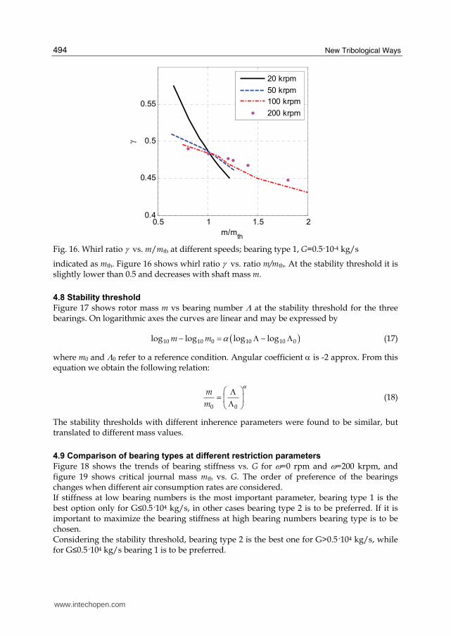
New Tribological Ways
494
05 1 15 204
045
05
055
mmth
γ
20 krpm
50 krpm
100 krpm
200 krpm
Fig 16 Whirl ratio γ vs mmth at different speeds bearing type 1 G=0510-4 kgs
indicated as mth Figure 16 shows whirl ratio γ vs ratio mmth At the stability threshold it is slightly lower than 05 and decreases with shaft mass m
48 Stability threshold
Figure 17 shows rotor mass m vs bearing number Λ at the stability threshold for the three bearings On logarithmic axes the curves are linear and may be expressed by
( )10 10 0 10 10 0log log log logm m αminus = Λ minus Λ (17)
where m0 and Λ0 refer to a reference condition Angular coefficient α is -2 approx From this equation we obtain the following relation
0 0
m
m
α⎛ ⎞Λ= ⎜ ⎟Λ⎝ ⎠ (18)
The stability thresholds with different inherence parameters were found to be similar but translated to different mass values
49 Comparison of bearing types at different restriction parameters
Figure 18 shows the trends of bearing stiffness vs G for ω=0 rpm and ω=200 krpm and figure 19 shows critical journal mass mth vs G The order of preference of the bearings changes when different air consumption rates are considered If stiffness at low bearing numbers is the most important parameter bearing type 1 is the best option only for Gle05104 kgs in other cases bearing type 2 is to be preferred If it is important to maximize the bearing stiffness at high bearing numbers bearing type is to be chosen Considering the stability threshold bearing type 2 is the best one for Ggt05104 kgs while for Gle05104 kgs bearing 1 is to be preferred
wwwintechopencom
Comparison between Different Supply Port Configurations in Gas Journal Bearings
495
101
10-2
10-1
100
101
102
Λ
mth
[kg]
bearing 1 G=05e-4 kgs
bearing 2 G=05e-4 kgs
bearing 3 G=05e-4 kgs
bearing 1 G=142e-4 kgs
bearing 2 G=142e-4 kgs
bearing 3 G=142e-4 kgs
Fig 17 Rotor mass m at stability threshold vs bearing number Λ for the three bearings
0 2 4 6
x 10-4
02
04
06
08
1
12
14
16ω=0 krpm
air consumption [kgs]
k
bearing 1
bearing 2
bearing 3
0 2 4 6
x 10-4
1
15
2
25
3
35
4ω=200 krpm
air consumption [kgs]
k
bearing 1
bearing 2
bearing 3
a) b)
Fig 18 Bearing stiffness k vs air consumption for the three bearings a) ω=0 rpm b) ω=200 krpm
wwwintechopencom
New Tribological Ways
496
05 1 15 2 25 3 35 4 45
x 10-4
004
006
008
01
012
014
016
018
02
022
024
air consumption [kgs]
mth
bearing 1
bearing 2
bearing 3
Fig 19 Rotor mass at stability threshold vs air consumption for the three bearings
5 Conclusion
Three bearing types were compared for different restriction parameters Bearing type 1 featured four supply ports situated in the bearing centre plane Bearing type 2 featured two sets of supply ports situated at z=L4 and z=3L4 Bearing type 3 also featured a central vented circumferential chamber The following conclusions were drawn
bull bearing type 2 in general is to be preferred to the other bearing types because of the higher stiffness and stability threshold at equal air consumption
bull with increasing Λ the attitude angle went from zero to max subsequently returning to zero max value was proportional to the difference between bearing stiffness at low and at high speeds
bull at the stability threshold the whirl ratio was slightly lower than 05
bull the curve of mth vs Λ on the logarithmic axes was linear and with changing restriction parameters the shaft critical mass changed by a factor regardless of speed
6 List of symbols
D bearing diameter F bearing force on journal G air mass flow rate L bearing axial length Rs pneumatic resistance of the supply hole Rh pneumatic resistance of clearance R0 gas constant in calculations R0=2876 m2s2K Re Reynolds number T0 absolute temperature in calculations T0=288 K
wwwintechopencom
Comparison between Different Supply Port Configurations in Gas Journal Bearings
497
b ratio of critical pressure to admission pressure b=0528 c damping coefficient cd supply hole discharge coefficient h local air clearance h0 clearance with rotor in centred position k bearing radial stiffness k non-dimensional bearing radial stiffness m rotor mass mth rotor mass at stability threshold nm number of nodes along axial and circumferential directions xyz cartesian coordinates pa ambient pressure pc supply hole downstream pressure ps bearing supply pressure
rθz cylindrical coordinates t time Λ bearing number Λ=6mωpa(D2h0)2 β steady attitude angle γ whirl ratio γ =νω ε eccentricity ratio μ dynamic viscosity in calculations μ=178910-6 Pas ν whirl frequency ζ bearing damping factor ω rotor angular speed
7 References
Andres LS (1990) Approximate analysis of turbulent hybrid bearings static and dynamic performance for centered operation ASME Journal of Tribology Vol 112 692-698
Belforte G Raparelli T Viktorov V (1999) Theoretical investigation of fluid inertia effects and stability of self-acting gas journal bearings ASME Journal of Tribology Vol 121 836-843
Belforte G Raparelli T Viktorov V Trivella A (2008) Discharge coefficients of orifice-type restrictor for aerostatic bearings Tribology International Vol 40 512-521
Cheng HS Pan CHT (1965) Stability analysis of gas-lubricated self-acting plain cylindrical journal bearings of finite length using Galerkinrsquos method ASME Journal of Basic Engineering 185-192
Colombo F Raparelli T Viktorov V (2009) Externally pressurized gas bearings a comparison between two supply holes configurations Tribology International Vol 42 303-310
Gross WA Zachmanaglou EC (1961) Perturbation solutions for Gas lubricating films Trans ASME Journal of Basic Engineering Vol 83 139-144
Han DC Park SS Kim WJ KimJW (1994) A study on the characteristics of externally pressurized gas bearings Precision Engineering Vol 16 No 3 164-173
Heller S Shapiro W Decker O (1971) A porous hydrostatic gas bearing for use in miniature turbomachinery ASLE Transactions 144-155
wwwintechopencom
New Tribological Ways
498
Lund JW (1968) Calculation of stiffness and damping properties of gas bearings ASME Journal of Lubrication Technology 793-803
Sawicki JT Capaldi RJ Adams ML (1997) Experimental and theoretical rotordynamic characteristics of a hybrid journal bearing ASME Journal of Tribology Vol 119 132-141
Su JCT Lie KN (2003) Rotation effects on hybrid air journal bearings Tribology International Vol 36 717-726
Su JCT Lie KN (2006) Rotor dynamic instability analysis on hybrid air journal bearings Tribology International Vol 39 No 1 238-248
Sun DC (1975) Stability of gas-lubricated externally pressurized porous journal bearings ASME Journal of Lubrication Technology 494-505
Wadhwa SS Sinhasant R Singh DV (1983) Analysis of orifice compensated externally pressurized gas bearing Tribology International Vol 16 No 4 203-211
Yang DW Chen CH Kang Y Hwang RM Shyr SS (2009) Influence of orifices on stability of rotor-aerostatic bearing system Tribology International Vol 42 1206-1219
Yoshikawa H Ota T Higashino K Nakai S (1999) Numerical analysis on dynamic characteristics of cryogenic hydrostatic journal bearing ASME Journal of Tribology Vol 121 879-885
Zhang RQ Chang HS (1995) A new type of hydrostatichydrodynamic gas journal bearing and its optimization for maximum stability Tribology Transactions Vol 38 No 3 589-594
wwwintechopencom
New Tribological WaysEdited by Dr Taher Ghrib
ISBN 978-953-307-206-7Hard cover 498 pagesPublisher InTechPublished online 26 April 2011Published in print edition April 2011
InTech EuropeUniversity Campus STeP Ri Slavka Krautzeka 83A 51000 Rijeka Croatia Phone +385 (51) 770 447 Fax +385 (51) 686 166wwwintechopencom
InTech ChinaUnit 405 Office Block Hotel Equatorial Shanghai No65 Yan An Road (West) Shanghai 200040 China
Phone +86-21-62489820 Fax +86-21-62489821
This book aims to recapitulate old informations available and brings new informations that are with the fashionresearch on an atomic and nanometric scale in various fields by introducing several mathematical models tomeasure some parameters characterizing metals like the hydrodynamic elasticity coefficient hardnesslubricant viscosity viscosity coefficient tensile strength It uses new measurement techniques verydeveloped and nondestructive Its principal distinctions of the other books that it brings practical manners tomodel and to optimize the cutting process using various parameters and different techniques namely usingwater of high-velocity stream tool with different form and radius the cutting temperature effect that can bemeasured with sufficient accuracy not only at a research lab and also with a theoretical forecast This bookaspire to minimize and eliminate the losses resulting from surfaces friction and wear which leads to a greatermachining efficiency and to a better execution fewer breakdowns and a significant saving A great part isdevoted to lubrication of which the goal is to find the famous techniques using solid and liquid lubricant filmsapplied for giving super low friction coefficients and improving the lubricant properties on surfaces
How to referenceIn order to correctly reference this scholarly work feel free to copy and paste the following
Federico Colombo Terenziano Raparelli and Vladimir Viktorov (2011) Comparison between Different SupplyPort Configurations in Gas Journal Bearings New Tribological Ways Dr Taher Ghrib (Ed) ISBN 978-953-307-206-7 InTech Available from httpwwwintechopencombooksnew-tribological-wayscomparison-between-different-supply-port-configurations-in-gas-journal-bearings
copy 2011 The Author(s) Licensee IntechOpen This chapter is distributedunder the terms of the Creative Commons Attribution-NonCommercial-ShareAlike-30 License which permits use distribution and reproduction fornon-commercial purposes provided the original is properly cited andderivative works building on this content are distributed under the samelicense

Comparison between Different Supply Port Configurations in Gas Journal Bearings
495
101
10-2
10-1
100
101
102
Λ
mth
[kg]
bearing 1 G=05e-4 kgs
bearing 2 G=05e-4 kgs
bearing 3 G=05e-4 kgs
bearing 1 G=142e-4 kgs
bearing 2 G=142e-4 kgs
bearing 3 G=142e-4 kgs
Fig 17 Rotor mass m at stability threshold vs bearing number Λ for the three bearings
0 2 4 6
x 10-4
02
04
06
08
1
12
14
16ω=0 krpm
air consumption [kgs]
k
bearing 1
bearing 2
bearing 3
0 2 4 6
x 10-4
1
15
2
25
3
35
4ω=200 krpm
air consumption [kgs]
k
bearing 1
bearing 2
bearing 3
a) b)
Fig 18 Bearing stiffness k vs air consumption for the three bearings a) ω=0 rpm b) ω=200 krpm
wwwintechopencom
New Tribological Ways
496
05 1 15 2 25 3 35 4 45
x 10-4
004
006
008
01
012
014
016
018
02
022
024
air consumption [kgs]
mth
bearing 1
bearing 2
bearing 3
Fig 19 Rotor mass at stability threshold vs air consumption for the three bearings
5 Conclusion
Three bearing types were compared for different restriction parameters Bearing type 1 featured four supply ports situated in the bearing centre plane Bearing type 2 featured two sets of supply ports situated at z=L4 and z=3L4 Bearing type 3 also featured a central vented circumferential chamber The following conclusions were drawn
bull bearing type 2 in general is to be preferred to the other bearing types because of the higher stiffness and stability threshold at equal air consumption
bull with increasing Λ the attitude angle went from zero to max subsequently returning to zero max value was proportional to the difference between bearing stiffness at low and at high speeds
bull at the stability threshold the whirl ratio was slightly lower than 05
bull the curve of mth vs Λ on the logarithmic axes was linear and with changing restriction parameters the shaft critical mass changed by a factor regardless of speed
6 List of symbols
D bearing diameter F bearing force on journal G air mass flow rate L bearing axial length Rs pneumatic resistance of the supply hole Rh pneumatic resistance of clearance R0 gas constant in calculations R0=2876 m2s2K Re Reynolds number T0 absolute temperature in calculations T0=288 K
wwwintechopencom
Comparison between Different Supply Port Configurations in Gas Journal Bearings
497
b ratio of critical pressure to admission pressure b=0528 c damping coefficient cd supply hole discharge coefficient h local air clearance h0 clearance with rotor in centred position k bearing radial stiffness k non-dimensional bearing radial stiffness m rotor mass mth rotor mass at stability threshold nm number of nodes along axial and circumferential directions xyz cartesian coordinates pa ambient pressure pc supply hole downstream pressure ps bearing supply pressure
rθz cylindrical coordinates t time Λ bearing number Λ=6mωpa(D2h0)2 β steady attitude angle γ whirl ratio γ =νω ε eccentricity ratio μ dynamic viscosity in calculations μ=178910-6 Pas ν whirl frequency ζ bearing damping factor ω rotor angular speed
7 References
Andres LS (1990) Approximate analysis of turbulent hybrid bearings static and dynamic performance for centered operation ASME Journal of Tribology Vol 112 692-698
Belforte G Raparelli T Viktorov V (1999) Theoretical investigation of fluid inertia effects and stability of self-acting gas journal bearings ASME Journal of Tribology Vol 121 836-843
Belforte G Raparelli T Viktorov V Trivella A (2008) Discharge coefficients of orifice-type restrictor for aerostatic bearings Tribology International Vol 40 512-521
Cheng HS Pan CHT (1965) Stability analysis of gas-lubricated self-acting plain cylindrical journal bearings of finite length using Galerkinrsquos method ASME Journal of Basic Engineering 185-192
Colombo F Raparelli T Viktorov V (2009) Externally pressurized gas bearings a comparison between two supply holes configurations Tribology International Vol 42 303-310
Gross WA Zachmanaglou EC (1961) Perturbation solutions for Gas lubricating films Trans ASME Journal of Basic Engineering Vol 83 139-144
Han DC Park SS Kim WJ KimJW (1994) A study on the characteristics of externally pressurized gas bearings Precision Engineering Vol 16 No 3 164-173
Heller S Shapiro W Decker O (1971) A porous hydrostatic gas bearing for use in miniature turbomachinery ASLE Transactions 144-155
wwwintechopencom
New Tribological Ways
498
Lund JW (1968) Calculation of stiffness and damping properties of gas bearings ASME Journal of Lubrication Technology 793-803
Sawicki JT Capaldi RJ Adams ML (1997) Experimental and theoretical rotordynamic characteristics of a hybrid journal bearing ASME Journal of Tribology Vol 119 132-141
Su JCT Lie KN (2003) Rotation effects on hybrid air journal bearings Tribology International Vol 36 717-726
Su JCT Lie KN (2006) Rotor dynamic instability analysis on hybrid air journal bearings Tribology International Vol 39 No 1 238-248
Sun DC (1975) Stability of gas-lubricated externally pressurized porous journal bearings ASME Journal of Lubrication Technology 494-505
Wadhwa SS Sinhasant R Singh DV (1983) Analysis of orifice compensated externally pressurized gas bearing Tribology International Vol 16 No 4 203-211
Yang DW Chen CH Kang Y Hwang RM Shyr SS (2009) Influence of orifices on stability of rotor-aerostatic bearing system Tribology International Vol 42 1206-1219
Yoshikawa H Ota T Higashino K Nakai S (1999) Numerical analysis on dynamic characteristics of cryogenic hydrostatic journal bearing ASME Journal of Tribology Vol 121 879-885
Zhang RQ Chang HS (1995) A new type of hydrostatichydrodynamic gas journal bearing and its optimization for maximum stability Tribology Transactions Vol 38 No 3 589-594
wwwintechopencom
New Tribological WaysEdited by Dr Taher Ghrib
ISBN 978-953-307-206-7Hard cover 498 pagesPublisher InTechPublished online 26 April 2011Published in print edition April 2011
InTech EuropeUniversity Campus STeP Ri Slavka Krautzeka 83A 51000 Rijeka Croatia Phone +385 (51) 770 447 Fax +385 (51) 686 166wwwintechopencom
InTech ChinaUnit 405 Office Block Hotel Equatorial Shanghai No65 Yan An Road (West) Shanghai 200040 China
Phone +86-21-62489820 Fax +86-21-62489821
This book aims to recapitulate old informations available and brings new informations that are with the fashionresearch on an atomic and nanometric scale in various fields by introducing several mathematical models tomeasure some parameters characterizing metals like the hydrodynamic elasticity coefficient hardnesslubricant viscosity viscosity coefficient tensile strength It uses new measurement techniques verydeveloped and nondestructive Its principal distinctions of the other books that it brings practical manners tomodel and to optimize the cutting process using various parameters and different techniques namely usingwater of high-velocity stream tool with different form and radius the cutting temperature effect that can bemeasured with sufficient accuracy not only at a research lab and also with a theoretical forecast This bookaspire to minimize and eliminate the losses resulting from surfaces friction and wear which leads to a greatermachining efficiency and to a better execution fewer breakdowns and a significant saving A great part isdevoted to lubrication of which the goal is to find the famous techniques using solid and liquid lubricant filmsapplied for giving super low friction coefficients and improving the lubricant properties on surfaces
How to referenceIn order to correctly reference this scholarly work feel free to copy and paste the following
Federico Colombo Terenziano Raparelli and Vladimir Viktorov (2011) Comparison between Different SupplyPort Configurations in Gas Journal Bearings New Tribological Ways Dr Taher Ghrib (Ed) ISBN 978-953-307-206-7 InTech Available from httpwwwintechopencombooksnew-tribological-wayscomparison-between-different-supply-port-configurations-in-gas-journal-bearings
copy 2011 The Author(s) Licensee IntechOpen This chapter is distributedunder the terms of the Creative Commons Attribution-NonCommercial-ShareAlike-30 License which permits use distribution and reproduction fornon-commercial purposes provided the original is properly cited andderivative works building on this content are distributed under the samelicense

New Tribological Ways
496
05 1 15 2 25 3 35 4 45
x 10-4
004
006
008
01
012
014
016
018
02
022
024
air consumption [kgs]
mth
bearing 1
bearing 2
bearing 3
Fig 19 Rotor mass at stability threshold vs air consumption for the three bearings
5 Conclusion
Three bearing types were compared for different restriction parameters Bearing type 1 featured four supply ports situated in the bearing centre plane Bearing type 2 featured two sets of supply ports situated at z=L4 and z=3L4 Bearing type 3 also featured a central vented circumferential chamber The following conclusions were drawn
bull bearing type 2 in general is to be preferred to the other bearing types because of the higher stiffness and stability threshold at equal air consumption
bull with increasing Λ the attitude angle went from zero to max subsequently returning to zero max value was proportional to the difference between bearing stiffness at low and at high speeds
bull at the stability threshold the whirl ratio was slightly lower than 05
bull the curve of mth vs Λ on the logarithmic axes was linear and with changing restriction parameters the shaft critical mass changed by a factor regardless of speed
6 List of symbols
D bearing diameter F bearing force on journal G air mass flow rate L bearing axial length Rs pneumatic resistance of the supply hole Rh pneumatic resistance of clearance R0 gas constant in calculations R0=2876 m2s2K Re Reynolds number T0 absolute temperature in calculations T0=288 K
wwwintechopencom
Comparison between Different Supply Port Configurations in Gas Journal Bearings
497
b ratio of critical pressure to admission pressure b=0528 c damping coefficient cd supply hole discharge coefficient h local air clearance h0 clearance with rotor in centred position k bearing radial stiffness k non-dimensional bearing radial stiffness m rotor mass mth rotor mass at stability threshold nm number of nodes along axial and circumferential directions xyz cartesian coordinates pa ambient pressure pc supply hole downstream pressure ps bearing supply pressure
rθz cylindrical coordinates t time Λ bearing number Λ=6mωpa(D2h0)2 β steady attitude angle γ whirl ratio γ =νω ε eccentricity ratio μ dynamic viscosity in calculations μ=178910-6 Pas ν whirl frequency ζ bearing damping factor ω rotor angular speed
7 References
Andres LS (1990) Approximate analysis of turbulent hybrid bearings static and dynamic performance for centered operation ASME Journal of Tribology Vol 112 692-698
Belforte G Raparelli T Viktorov V (1999) Theoretical investigation of fluid inertia effects and stability of self-acting gas journal bearings ASME Journal of Tribology Vol 121 836-843
Belforte G Raparelli T Viktorov V Trivella A (2008) Discharge coefficients of orifice-type restrictor for aerostatic bearings Tribology International Vol 40 512-521
Cheng HS Pan CHT (1965) Stability analysis of gas-lubricated self-acting plain cylindrical journal bearings of finite length using Galerkinrsquos method ASME Journal of Basic Engineering 185-192
Colombo F Raparelli T Viktorov V (2009) Externally pressurized gas bearings a comparison between two supply holes configurations Tribology International Vol 42 303-310
Gross WA Zachmanaglou EC (1961) Perturbation solutions for Gas lubricating films Trans ASME Journal of Basic Engineering Vol 83 139-144
Han DC Park SS Kim WJ KimJW (1994) A study on the characteristics of externally pressurized gas bearings Precision Engineering Vol 16 No 3 164-173
Heller S Shapiro W Decker O (1971) A porous hydrostatic gas bearing for use in miniature turbomachinery ASLE Transactions 144-155
wwwintechopencom
New Tribological Ways
498
Lund JW (1968) Calculation of stiffness and damping properties of gas bearings ASME Journal of Lubrication Technology 793-803
Sawicki JT Capaldi RJ Adams ML (1997) Experimental and theoretical rotordynamic characteristics of a hybrid journal bearing ASME Journal of Tribology Vol 119 132-141
Su JCT Lie KN (2003) Rotation effects on hybrid air journal bearings Tribology International Vol 36 717-726
Su JCT Lie KN (2006) Rotor dynamic instability analysis on hybrid air journal bearings Tribology International Vol 39 No 1 238-248
Sun DC (1975) Stability of gas-lubricated externally pressurized porous journal bearings ASME Journal of Lubrication Technology 494-505
Wadhwa SS Sinhasant R Singh DV (1983) Analysis of orifice compensated externally pressurized gas bearing Tribology International Vol 16 No 4 203-211
Yang DW Chen CH Kang Y Hwang RM Shyr SS (2009) Influence of orifices on stability of rotor-aerostatic bearing system Tribology International Vol 42 1206-1219
Yoshikawa H Ota T Higashino K Nakai S (1999) Numerical analysis on dynamic characteristics of cryogenic hydrostatic journal bearing ASME Journal of Tribology Vol 121 879-885
Zhang RQ Chang HS (1995) A new type of hydrostatichydrodynamic gas journal bearing and its optimization for maximum stability Tribology Transactions Vol 38 No 3 589-594
wwwintechopencom
New Tribological WaysEdited by Dr Taher Ghrib
ISBN 978-953-307-206-7Hard cover 498 pagesPublisher InTechPublished online 26 April 2011Published in print edition April 2011
InTech EuropeUniversity Campus STeP Ri Slavka Krautzeka 83A 51000 Rijeka Croatia Phone +385 (51) 770 447 Fax +385 (51) 686 166wwwintechopencom
InTech ChinaUnit 405 Office Block Hotel Equatorial Shanghai No65 Yan An Road (West) Shanghai 200040 China
Phone +86-21-62489820 Fax +86-21-62489821
This book aims to recapitulate old informations available and brings new informations that are with the fashionresearch on an atomic and nanometric scale in various fields by introducing several mathematical models tomeasure some parameters characterizing metals like the hydrodynamic elasticity coefficient hardnesslubricant viscosity viscosity coefficient tensile strength It uses new measurement techniques verydeveloped and nondestructive Its principal distinctions of the other books that it brings practical manners tomodel and to optimize the cutting process using various parameters and different techniques namely usingwater of high-velocity stream tool with different form and radius the cutting temperature effect that can bemeasured with sufficient accuracy not only at a research lab and also with a theoretical forecast This bookaspire to minimize and eliminate the losses resulting from surfaces friction and wear which leads to a greatermachining efficiency and to a better execution fewer breakdowns and a significant saving A great part isdevoted to lubrication of which the goal is to find the famous techniques using solid and liquid lubricant filmsapplied for giving super low friction coefficients and improving the lubricant properties on surfaces
How to referenceIn order to correctly reference this scholarly work feel free to copy and paste the following
Federico Colombo Terenziano Raparelli and Vladimir Viktorov (2011) Comparison between Different SupplyPort Configurations in Gas Journal Bearings New Tribological Ways Dr Taher Ghrib (Ed) ISBN 978-953-307-206-7 InTech Available from httpwwwintechopencombooksnew-tribological-wayscomparison-between-different-supply-port-configurations-in-gas-journal-bearings
copy 2011 The Author(s) Licensee IntechOpen This chapter is distributedunder the terms of the Creative Commons Attribution-NonCommercial-ShareAlike-30 License which permits use distribution and reproduction fornon-commercial purposes provided the original is properly cited andderivative works building on this content are distributed under the samelicense

copy 2011 The Author(s) Licensee IntechOpen This chapter is distributedunder the terms of the Creative Commons Attribution-NonCommercial-ShareAlike-30 License which permits use distribution and reproduction fornon-commercial purposes provided the original is properly cited andderivative works building on this content are distributed under the samelicense