Embed Size (px)
Citation preview
International Journal of Aviation, International Journal of Aviation,
Aeronautics, and Aerospace Aeronautics, and Aerospace
Volume 2 Issue 1 Article 2
3-2-2015
Comparison of Aircraft Tire Wear with Initial Wheel Rotational Comparison of Aircraft Tire Wear with Initial Wheel Rotational
Speed Speed
Abdurrhman A. Alroqi University of Sussex, [email protected] Weiji Wang University of Sussex, [email protected]
Follow this and additional works at: https://commons.erau.edu/ijaaa
Part of the Aeronautical Vehicles Commons
Scholarly Commons Citation Scholarly Commons Citation Alroqi, A. A., & Wang, W. (2015). Comparison of Aircraft Tire Wear with Initial Wheel Rotational Speed. International Journal of Aviation, Aeronautics, and Aerospace, 2(1). https://doi.org/10.15394/ijaaa.2015.1043
This Article is brought to you for free and open access by the Journals at Scholarly Commons. It has been accepted for inclusion in International Journal of Aviation, Aeronautics, and Aerospace by an authorized administrator of Scholarly Commons. For more information, please contact [email protected].
Comparison of Aircraft Tire Wear with Initial Wheel Rotational Speed Comparison of Aircraft Tire Wear with Initial Wheel Rotational Speed
Cover Page Footnote Cover Page Footnote The authors would like to acknowledge University of Sussex for its support with the literature and related resources.
This article is available in International Journal of Aviation, Aeronautics, and Aerospace: https://commons.erau.edu/ijaaa/vol2/iss1/2
In this paper, the landing impact of an aircraft is described using a
physical model of a single wheel in the main landing gear. The purpose of this
study is to understand potential tire-life improvements that could be made by
reducing abrasive skidding between aircraft tires and runway surfaces
immediately after touchdown.
The physical model assumes the following chain of events during a
typical landing: Firstly, the landing gear is extended during the aircraft
approach towards the runway. The main wheels first contact the ground while
the wheels are not spinning at ground-speed. A difference between the
translational ground-speed of the aircraft and the tangential speed of the tire
radius results in a skid which reduces in severity as the wheels accelerate to
match the forward speed of the aircraft along the runway. A small cloud of
smoke is often visible following the initial touchdown. The cause of landing
smoke has been identified as resulting from high friction between the tire and
runway surfaces (Cadle & Williams, 1978). This friction generates significant
heat, which can trigger burning of the softer surface (Tomita, 1964). The
softer surface is the tire tread, which for civilian aircraft is made of nearly
100% natural rubber (Hunter, 1997), which has highly elastic dynamic
properties and high resistance to heat (De & White, 2001).
The main landing gear of a Boeing 747-400 is modelled as a one-
dimensional mass-spring-damper system for analysis of forces during the short
period between touchdown and the wheels spinning up to match the ground
speed of the aircraft. Distinct dynamic states of the tire during landing have
been identified in this case study: touchdown, traction-limited skidding, tire
spin-up and free rolling.
Literature Review
Literature describing the physical process that causes aircraft tire
rubber to vaporize under landing loads is sparse, although multiple studies
have been reported in the automotive field. Tire skid-marks are caused by
material being removed by abrasion between slipping tires and the asphalt
runway surface. Persson (2006) states that the friction force generated between
the tire and asphalt surfaces is related to the internal friction of the rubber,
which is a bulk property. The hysteretic friction component is determined by
gripping and sliding of the rubber over a rough surface. These oscillating
forces lead to energy dissipation, which can cause heating of the tire material
to a level where smoke is produced.
Few studies were found to have attempted simulation modelling of
longitudinal tire dynamics during landings. In the first, Padovan, Kazempour
and Kim (1990) built an energy-balance model to compute the rate of work
due to interfacial friction between tire and runway surfaces and its effect on
1
Alroqi and Wang: Comparison of Aircraft Tire Wear with Initial Wheel Rotational Speed
Published by Scholarly Commons, 2015
the growth of wheel rotary inertia and slip work. In the study, calculations
were based on a model of the space-shuttle, which experiences a large amount
of tire wear per landing. A simple Coulomb-friction formulation �� � ���
tire friction model was employed, using a constant friction coefficient µ and a
non-linear curve fitted to experimental data to express vertical tire load ��.
Padovan, Kazempour and Kim (1990) concluded from various simulations that
tire wear was increased with horizontal landing speed, sink rate and surface
friction coefficients.
Slagmaat (1992) investigated suitable tire models for simulating
longitudinal aircraft tire dynamics and found the Pacejka “magic formula”
models, popular in automotive literature, were not suitable to represent the
fast-dynamics in aircraft landings. Significant simplifications were applied to
the Pacejka tire model in (Slagmaat, 1992), and a multi-body nonlinear
landing gear model was implemented for vertical tire-load simulation,
although comparisons with experimental results were not made due to a lack
of reliable experimental data being available.
In (Li & Jiao, 2013), a simulation model was built for an anti-lock
braking system (ABS) to be used on large aircraft. The highly dynamic tire
forces were successfully modeled in that study with the use of a modern
LuGre tire model.
Besselink (2000) produced a sophisticated model for simulating lateral
“shimmy” oscillations in main landing gear of a Boeing 747-400 aircraft.
Although the scope of this work does not involve lateral dynamics, some
important experimental data was recorded, including experimental wheel-
speed time traces measured on a Boeing 747-400 aircraft during landing,
which are useful for validating our simulations. Measured data in both
Besselink (2000) and Khapane (2004) show aircraft tires accelerating from
zero rotational speed to a free-rolling velocity within about 0.1 seconds from
touchdown.
However, some example aircraft wheel spinner patents designed to
prevent the aircraft landing smoke are presented here. No valid proof of the
systems that those patents define validated to eliminate landing smoke and tire
wear arose in the literature review, and to our knowledge no aircraft industries
use these patents. Aircraft landings continue to generate smoke, a screeching
sound, flat spots on tires, and the need to periodically replace the tires;
indicating a significant issue that is addressed in this paper. Patented solutions
have been suggested by Beazley (1947) and others. The benefits of a
successful design include longer tire life, improved landing safety, reduced
parts fatigue and maintenance costs, less tarmac rubber-cleaning, a lower risk
of tire blow-outs, and a lower risk of tire debris being ingested into jet engines.
Additionally, there are environmental benefits such as reduction of tire smoke,
2
International Journal of Aviation, Aeronautics, and Aerospace, Vol. 2 [2015], Iss. 1, Art. 2
https://commons.erau.edu/ijaaa/vol2/iss1/2DOI: https://doi.org/10.15394/ijaaa.2015.1043
noise, and air pollution caused by the disintegrating tires (Beazley, 1947). As a
result, various ideas have circulated since as early as the 1940s, several of
which are presented here.
Patents for aircraft wheel rotational devices and methods focus on
ideas that range from the simple to mechanically complex. The literature
indicates that some pre-rotating systems are mechanically complex, heavy, or
not durable. Therefore, several patents focus on passive air flow systems that
require modifications to the wheels themselves to cause the air stream to rotate
the descending wheels before they touch the ground. Most of these are wheel-
mounted accessories intended to utilize the air stream during descent to start
aircraft tires rotating before touchdown, while others are complex systems
utilising magnetic, hydraulics, compressed air and gas, and other mechanical
systems.
Pre-rotation is the primary means of getting tires on an airborne plane
to begin spinning before they hit the tarmac on landing. Khal and Khal (2013),
utilize a flap system made of a flexible resin plastic base, then Kevlar-type
material, then a top layer of similar material as the base, all bonded together
with stitching, adhesive, and/or thermoplastic bonding. Each disc-shaped piece
has passive, auto-retracting flaps or vanes that open when exposed to the air
stream created by the descending plane. Above the horizontal centreline of the
wheel, the hinged flap leads into wind and the flaps close; below the tire's
centreline, air pushes the flaps open and fully open at the bottom; this torque is
aerodynamically generated, forcing the wheel into rotation. Additional
structures keep the flap from exceeding 90 degrees when open. One
complication of operating this device is that the outer circumference of the
disc may include a weighted ring to supply centrifugal force to reset a disc
displaced by a rough landing, bolting into the tires themselves may
compromise their inherent structure. Thus, this assembly does not appear to be
as viable a design as some others.
Horvath and Szoke (2006), avoid the addition of an assembly to the
wheel and instead alter the tire’s design to incorporate curved air foils that
protrude from both sides of each tire. Placing the foils on both sides, it is
claimed, will minimize protrusion. The inventors suggest the foils could also
be attached to existing tires and made of “durable material”, suggesting
rubber, synthetic rubber, and closed or open cell foam. This material can then
be bonded to “the carcass plies by nylon fabric or other methods, and covered
by rubber or other synthetic materials”. While there is a potentially good
concept, Horvath and Szoke have not executed their idea in real-world testing.
Moreover, such a tire design change would likely also require all new wheel
assemblies and enclosures to accommodate them, which is neither cost
effective nor feasible.
3
Alroqi and Wang: Comparison of Aircraft Tire Wear with Initial Wheel Rotational Speed
Published by Scholarly Commons, 2015
Numerous inventions have been registered to pre-spin aircraft tires before
touchdown, although none of the patents researched mentioned any estimate
on expected improvements on tire life. The goal of this study is to predict the
difference in tire wear between pre-spun and un-spun aircraft wheels.
Simulation Model
The following subsections describe physical relationships used in the
development of a Simulink model that is used to predict the forces acting on a
tire during a typical landing event, and also predict the tire wear with different
initial conditions.
The following assumptions (with the support of references) were used to
simplify calculations.
• The pilot does not brake during the spin-up phase after touchdown.
This avoidance of immediate brake use avoids locked wheels,
increased skidding, and a tire flat spot that leads to more tire and brake
pad wear (United states air force, 2007).
• The aircraft will touchdown with all of the main wheels and zero wing
lift (Jingzhe, 2007) and (Daidzic & Shrestha , 2008); the landing is
smooth with an acceptable sink rate (vertical speed) to be absorbed by
the shock absorbers and tires. Additionally, the nose wheel will not
touch the ground for two seconds after the main wheels. This latter
assumption is because the aircraft may touchdown on the runway with
some lift still generated by the wing, and the aircraft weight will not be
applied equally to all wheels simultaneously because it might be
affected by cross wind, and pilot action. Furthermore, the aircraft may
land on one wheels leg, which leads to hard landing and strong forces
applied to the wheels (FAA, 2004).
• Static friction coefficients of the tire and runway materials are constant
throughout the landing process, and a Lugre tire model (Canudas-de-
Wit, Tsiotras, Velenis, Basset & Gissinger, 2003) is used to determine
the dynamic friction forces acting friction.
• Shock absorbers in the landing gear structure absorb the majority
highly dynamic vertical forces, and tire deflection is assumed to vary
linearly with vertical load according to a spring law.
• Wheel spin-up or “skid” time is the measured time between touchdown
and the landing gear wheels reaching a steady speed that matches the
ground speed of the aircraft.
Landing Gear Dynamics
The mass-spring-damper system depicted in Figure 1 was used to
model vertical forces acting on the aircraft mass and tires contact patch. The
4
International Journal of Aviation, Aeronautics, and Aerospace, Vol. 2 [2015], Iss. 1, Art. 2
https://commons.erau.edu/ijaaa/vol2/iss1/2DOI: https://doi.org/10.15394/ijaaa.2015.1043
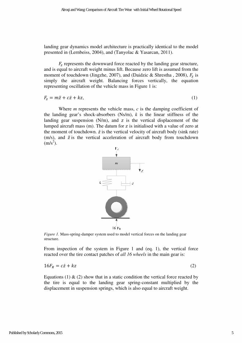
landing gear dynamics model architecture is practically identical to the model
presented in (Lernbeiss, 2004), and (Tanyolac & Yasarcan, 2011).
�� represents the downward force reacted by the landing gear structure,
and is equal to aircraft weight minus lift. Because zero lift is assumed from the
moment of touchdown (Jingzhe, 2007), and (Daidzic & Shrestha , 2008), �� is
simply the aircraft weight. Balancing forces vertically, the equation
representing oscillation of the vehicle mass in Figure 1 is:
�� � � � � � �, (1)
Where m represents the vehicle mass, c is the damping coefficient of
the landing gear’s shock-absorbers (Ns/m), k is the linear stiffness of the
landing gear suspension (N/m), and is the vertical displacement of the
lumped aircraft mass (m). The datum for is initialised with a value of zero at
the moment of touchdown. is the vertical velocity of aircraft body (sink rate)
(m/s), and is the vertical acceleration of aircraft body from touchdown
(m/s2).
Figure 1. Mass-spring-damper system used to model vertical forces on the landing gear
structure.
From inspection of the system in Figure 1 and (eq. 1), the vertical force
reacted over the tire contact patches of all 16 wheels in the main gear is:
16�� � � � � (2)
Equations (1) & (2) show that in a static condition the vertical force reacted by
the tire is equal to the landing gear spring-constant multiplied by the
displacement in suspension springs, which is also equal to aircraft weight.
5
Alroqi and Wang: Comparison of Aircraft Tire Wear with Initial Wheel Rotational Speed
Published by Scholarly Commons, 2015
The damping term c in (eq. 2) shows the vertical force acting on the tire at the
instant of touchdown will be larger at higher sink rates, i.e. the vertical
velocity at which the wheel initially hits the ground.
The combined spring constant for the main landing gear of a Boeing
747-400 (four oleo struts in parallel) is 5×10⁶ N/m and the damping
coefficient of the landing gear shock absorber is 5.473×10⁶ Ns/m (Jingzhe,
2007). The aircraft mass is 295,743 kg (Boeing, 2011), so in a static condition
the force FR is equal to 181.33 kN (mg/16).
Wheel Geometry
The wheels are assumed to start to spin up from zero rotational speed
when the aircraft lands until they reach the aircraft forward speed, and then
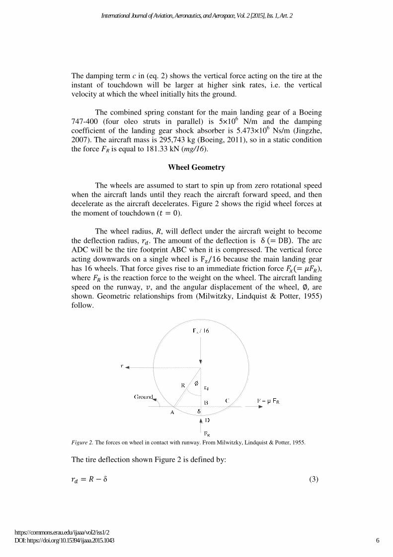
decelerate as the aircraft decelerates. Figure 2 shows the rigid wheel forces at
the moment of touchdown (� � 0).
The wheel radius, R, will deflect under the aircraft weight to become
the deflection radius, ��. The amount of the deflection is δ �� DB�. The arc
ADC will be the tire footprint ABC when it is compressed. The vertical force
acting downwards on a single wheel is F�/16 because the main landing gear
has 16 wheels. That force gives rise to an immediate friction force ���� ���),
where �� is the reaction force to the weight on the wheel. The aircraft landing
speed on the runway, �, and the angular displacement of the wheel, , are
shown. Geometric relationships from (Milwitzky, Lindquist & Potter, 1955)
follow.
Figure 2. The forces on wheel in contact with runway. From Milwitzky, Lindquist & Potter, 1955.
The tire deflection shown Figure 2 is defined by:
�� � " # δ (3)
6
International Journal of Aviation, Aeronautics, and Aerospace, Vol. 2 [2015], Iss. 1, Art. 2
https://commons.erau.edu/ijaaa/vol2/iss1/2DOI: https://doi.org/10.15394/ijaaa.2015.1043
If there was enough slip across the extent of the tire contact patch then the tire
might rotate as if the true radius were the geometric value of the axle height
��. However, this is not the case for a generalized pneumatic tire with bias-ply
construction, although an effective radius �$ can be used, as in (Daugherty,
2003) which generalizes the rolling radius across the tire contact patch AC.
From trigonometry the angular displacement between the center and edge of
the contact patch is:
� sin() *�+(,-+� (4)
And the horizontal translation of rolling is:
./ � *R1 # r�1 (5)
Combining (eq. 4) with (eq. 5) yields the effective rolling radius;
�$ � 34 � *5+(6-+
789:;<=+:>-+=
� �<)(?-+@+
789:;<)(?-+@+
(6)
Proof in (Milwitzky, Lindquist & Potter, 1955) concludes that the right-hand side
of (eq. 6) is closely approximated by the linear function 1�A,-
B , so that:
�$ C 1�A,-B (7)
or, since �� � " # δ from (eq. 3) ,
�$ � " # δ
B . (8)
The tire deflection can be calculated by modeling linear deflection from
deflection vs. load data in (Lindsley & Talekar, 2000) with a spring constant
of �D � 1.7F10G meters per Newton vertical load ��D � �� H⁄ �, which gives a
constant effective tire rolling radius of 0.586 m when the aircraft is in a static
condition. Tire geometry data is given in Table 2.
LuGre Tire/Road Friction Model
The LuGre model was selected for use in preference to static brush
models (Bartram, Mavros, & Biggs, 2010) for the LuGre model’s ability to
capture fast dynamic conditions. The dynamic Dahl model (Dahl, 1968) is
7
Alroqi and Wang: Comparison of Aircraft Tire Wear with Initial Wheel Rotational Speed
Published by Scholarly Commons, 2015
unable to model the Stribeck effect, which describes sticking and slipping
motion, whereas LuGre model can. The LuGre tire model only requires 6
input parameters (given in Table 1), unlike Pacejka models which can require
a vast amount of curve-fitting parameters to which the force output can be
sensitive (Hamza, 2014). As explained by (Slagmaat, 1992), the Pacejka
"magic formula" is not a first order differential equation like conventional tire
models, but an algebraic equation simply fitted to steady-state observations.
The lack of dependence on time-derivatives results in less accurate predictions
if transient behavior is of interest. Another reason for not choosing the "magic
formula", which is popular in automotive literature, as computational tire
model is the lack of appropriate parameter values for aircraft tires. Parameters
in Pacejka’s “magic formula” form curve fittings of force coefficients from
measurements under varying normal loads. The range of aircraft tire normal
loads is up to fifteen times wider than typical automotive tire loads and starts
from zero, rendering car tire curve fittings invalid in most of the used range in
the aircraft tire.
The longitudinal friction force �� that acts at the tire contact point and
acts to accelerate the wheel rotationally is modeled using the LuGre tire model
described by (Li & Jiao, 2013).
The aircraft tire/runway friction coefficient is defined by the ratio of
friction force and the normal force, which can be expressed as:
� � JKJ= (9)
where the friction coefficient µ is a complex function of the aircraft
longitudinal slip and other factors, such as tire and runway conditions.
Longitudinal slip between a point on the tire’s outer radius and the ground is
defined by:
L � M(,NOM (10)
where v is the aircraft’s forward speed along the runway and ω is the
rotational speed of the wheel in radians per second.
The LuGre tire model formulation is based on a distribution of
longitudinal and normal forces distributed within the tire contact patch
(Canudas-de-Wit, Tsiotras, Velenis, Basset & Gissinger, 2003) although, as
demonstrated in (ESDU, 1995), the lumped LuGre model is a good
approximation of the distributed LuGre model, as they have similar steady-
state and dynamic behavior.
8
International Journal of Aviation, Aeronautics, and Aerospace, Vol. 2 [2015], Iss. 1, Art. 2
https://commons.erau.edu/ijaaa/vol2/iss1/2DOI: https://doi.org/10.15394/ijaaa.2015.1043
Frictional forces in the LuGre model depend upon evolution of the
mean internal friction state ̃, which is effectively the average stretched
displacement of rubber across the tire contact patch. The internal friction state
within the contact patch, from (Canudas-de-Wit, Petersen & Shiriaev, 2003) is
defined by the differential equation:
��Q�D � �, # RS|M>|
U�M>,MV� ̃ (11)
Where WX is the normalized tire stiffness, and �, is the relative speed between
a point tangential to the outer tire surface and the forward speed of the aircraft
along the runway:
�, � � # �$Y (12)
The symbol Z in (eq. 11) is the function which defines the Stribeck tire-road
sliding friction (Andersson, Soderberg, & Bjorklund, 2007):
Z��, , �[� � �\ � ��] # �\�^(|M> MV⁄ |S._ (13)
where �\ is the normalized Coulomb friction, �] is the normalized static
friction ( �\ ` �] , ∈ [0, 1]) and �[ is the Stribeck relative velocity, all of
which are physical characteristics observed upon contact between the tire
rubber and runway asphalt materials. Stribeck velocity �[ is a boundary value
of relative velocity at which surfaces stop sticking to one another and begin to
slide relative to one another (Wojewoda, Stefanski, Wiercigroch, &
Kapitaniak, 2008).
Dynamic stiffness and damping properties for the tire material are
included to measure the tire/road friction force applied on the ground across
the entire contact patch over time:
�� � bWX̃ � W) ��Q�D � W1�,c �� (14)
Where W) is the normalized tire damping, and W1 is the normalized tire viscous
friction. Combining equations (9) and (14), the friction coefficient can be
expressed with:
� � bWX̃ � W) ��Q�D � W1�,c (15)
Suitable LuGre tire model parameters for the rubber used in aircraft tires are
given in Table 1 (Li & Jiao, 2013).
9
Alroqi and Wang: Comparison of Aircraft Tire Wear with Initial Wheel Rotational Speed
Published by Scholarly Commons, 2015
Table 1
LuGre tire model parameters.
Name WX W) W1 �\ �] �[
Value 1 0.1487 0.0038 0.5 0.9 12.5
Units 1/m s/m s/m - - m/s
Inspection of (eq. 15) and Table 1 entails that the friction between tire and
runway surface are strongly dependent upon the internal friction state and
stretching of rubber within the tire contact patch. Friction coefficient with
relative slip ratio L is shown in Figure 3 for the tire model described above.
Figure 3 shows that the friction coefficient varies most rapidly between slip
ratios of zero to 0.1 where a maximum is observed. Beyond the peak friction
value, the amount of tractive friction force available decreases with increasing
slip and the tire becomes less effective at providing traction.
Wheel Inertia
The wheel moment of inertia consists of two components, the tire and rim
moments of inertia, as in (Day, 2014):
d � dD � d, (16)
where dD and d, are the tire and rim moments of inertia, respectively. The tire
can be assumed to be a circular ring; therefore its moment of inertia, If (circular ring) is:
dD � �D"1 (17)
where mf represents the tire mass and R is its radius. The other wheel part is
the rim, which can be approximated as two parts, a flat circular plate, and a
circular ring. The mass of the flat plate is assumed equal to that of the circular
ring. Therefore the rim moment of inertia is:
d, � d,�hi,hjkl,� � d,�mklD� (18)
10
International Journal of Aviation, Aeronautics, and Aerospace, Vol. 2 [2015], Iss. 1, Art. 2
https://commons.erau.edu/ijaaa/vol2/iss1/2DOI: https://doi.org/10.15394/ijaaa.2015.1043
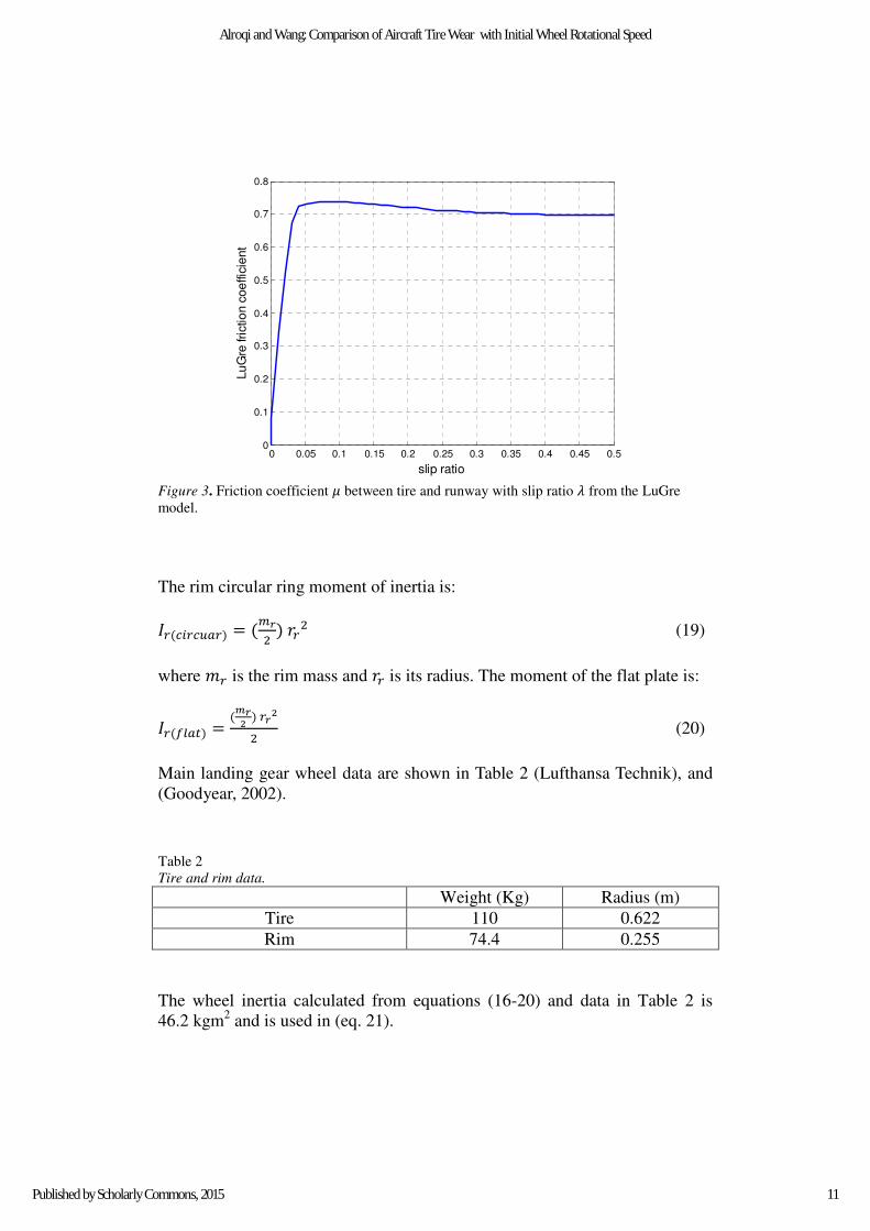
Figure 3. Friction coefficient � between tire and runway with slip ratio L from the LuGre
model.
The rim circular ring moment of inertia is:
d,�hi,hjl,� � �n>1 � �,1 (19)
where �, is the rim mass and �, is its radius. The moment of the flat plate is:
d,�mklD� � �o>+ � ,>+
1 (20)
Main landing gear wheel data are shown in Table 2 (Lufthansa Technik), and
(Goodyear, 2002).
Table 2
Tire and rim data.
Radius (m) Weight (Kg)
0.622 110 Tire
0.255 74.4 Rim
The wheel inertia calculated from equations (16-20) and data in Table 2 is
46.2 kgm2 and is used in (eq. 21).
0 0.05 0.1 0.15 0.2 0.25 0.3 0.35 0.4 0.45 0.50
0.1
0.2
0.3
0.4
0.5
0.6
0.7
0.8
slip ratio
Lu
Gre
frictio
n c
oe
ffic
ient
11
Alroqi and Wang: Comparison of Aircraft Tire Wear with Initial Wheel Rotational Speed
Published by Scholarly Commons, 2015
Wheel Rotational Dynamics
The friction force �� (eq. 14) acts at the tire contact patch, distanced
from the wheel’s axle by the effective radius. Utilising the rotational form of
Newton’s 2nd
law, rotational acceleration of the wheel is:
Y � ���$/d (21)
where Y is the wheel acceleration (rad/s2), and re is the effective radius of the
wheel under the immediate loading conditions.
Wheel speed with time is simply calculated as the integral of (eq. 21) with
respect to time, plus an initial wheel speed:
Y � p Y q� � YiriD (22)
Where, Y is the wheel speed (rad/s), and YiriD is the wheel speed prior to
touchdown.
Aircraft Landing Path and Speed
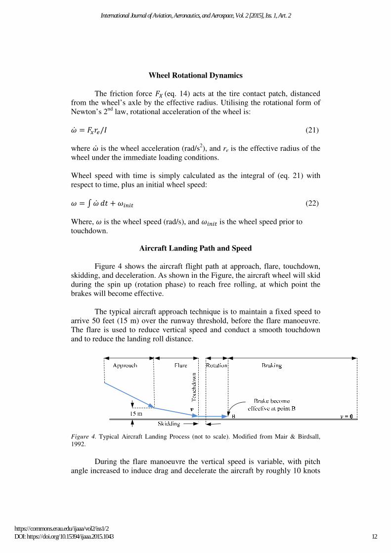
Figure 4 shows the aircraft flight path at approach, flare, touchdown,
skidding, and deceleration. As shown in the Figure, the aircraft wheel will skid
during the spin up (rotation phase) to reach free rolling, at which point the
brakes will become effective.
The typical aircraft approach technique is to maintain a fixed speed to
arrive 50 feet (15 m) over the runway threshold, before the flare manoeuvre.
The flare is used to reduce vertical speed and conduct a smooth touchdown
and to reduce the landing roll distance.
Figure 4. Typical Aircraft Landing Process (not to scale). Modified from Mair & Birdsall,
1992.
During the flare manoeuvre the vertical speed is variable, with pitch
angle increased to induce drag and decelerate the aircraft by roughly 10 knots
12
International Journal of Aviation, Aeronautics, and Aerospace, Vol. 2 [2015], Iss. 1, Art. 2
https://commons.erau.edu/ijaaa/vol2/iss1/2DOI: https://doi.org/10.15394/ijaaa.2015.1043
(Ochi & Kanai, 1999). Li and Jiao (2013) states that the vertical sink rate at
the instant of touchdown for the Boeing 747-400 aircraft typically varies
between 1.5 m/s and 3 m/s.
A sink rate of 2 m/s is used at the start of each landing simulation in
this study, and horizontal speed at touchdown speed is equal to the approach
speed from Boeing (2011), 80.78 m/s, minus 5.14 m/s from flare deceleration
(Ochi & Kanai, 1999), resulting in a horizontal touchdown speed of 75.6 m/s.
That horizontal speed is assumed constant for the entire simulation, which is
small and within the assumed two-second period before the pilot applies the
brakes.
Tire Wear
The primary location of the abrasive action between tire and pavement
during vehicle operation is on a thin layer of rubber in the tread immediately
in contact with the road, called the footprint. This layer and the underlying belt
layers are cyclically compressed and uncompressed, creating shear stresses
and strains. These stresses and strains make up the frictional work between
surfaces, which in turn causes wear of the tread. The magnitude of tread
erosion is a function of the intensity and duration of the frictional work, the
nature of the pavement, properties of the rubber, and other environmental
factors (Li & Jiao, 2013).
Different methods independently attempt to quantify tire wear by
isolating all but a few factors. The method by (Saibel & Tsai, 1969),
aggregating abrasion pattern, slippage, and temperature effects, fatigue theory
and the geometry of the contact surface. Other methods, such as Pacejka’s
“Magic Formula” (Braghin, Cheli, Melzi, & Resta, 2006) uses laboratory
observed data to determine constants that best fit tire wear models. Pacejka’s
series of tire design models were named “magic” because they are not formed
on any physical basis, but fit a wide array of construction and operating
conditions.
The Archard wear theory is a simple model used to associate tire wear
with slip, and is based around the theory of asperity contact. The calculation of
adhesive wear is proposed by Archard (Zglimbea, Finca, Greaban, &
Constantin, 2009), (Li, Zhang, & Guan, 2012), (Zhang, Zhang, & Yu, 2012),
and (Tong, Wang & Jin, 2012).
The volume of tire material eroded in Archard wear theory is defined as:
s � t J=u v (23)
13
Alroqi and Wang: Comparison of Aircraft Tire Wear with Initial Wheel Rotational Speed
Published by Scholarly Commons, 2015
where V represents the total volume of wear amount (m3), K is the wear
coefficient, �� is the normal load applied to the tire contact patch (eq. 2), H is
the hardness of the softer material in the contact (in our case the tire rubber),
and L is the slip distance.
In the process of tire rolling, the slip distance can be defined as the integral of
slip ratio from (eq. 10) with respect to time:
v � p L q�. (24)
The rate of volume wear is then described as:
s � t J=u L (25)
Where s is the tire wear volumetric rate (m3/s). Because K and H are
constants in the simple Archard model, the rate of volumetric tire wear is
directly proportional to the product normal force and slip ratio or relative
slipping velocity between the two contact materials. The inclusion of normal
force implies that tire wear will scale linearly with aircraft mass. This implies
that tire wear is roughly proportional to the amount of frictional work (force ×
slipping distance) at slip ratios above the peak in Figure 3; where µ is
practically constant, which is also reported to be a reasonable in (Tong, & Jin,
2012), and (Lupker, Montanaro, Donadio, Gelosa, & Vis, 2002).
Eliminating the constants K and H, a “normalized wear” measure can
be used to measure the relative difference in wear between landing simulations
using different initial conditions without needing the material properties used
in a calculation of volumetric wear. This normalized wear factor simply
eliminates the constant wear coefficient and material hardness K and H from
(eq. 25) to consider only the varying normal force and slip ratio. Normalized
wear volume (Ns) is then simply:
sw � p��� · L� q�. (26)
Normalised wear volume expressed in (eq. 26) is analogous to the “slip
work” measure used in (Padovan, Kazempour & Kim, 1990), and was used in
that study to represent the amount of tire wear between simulations and
physical measurements.
Simulation Model Details
A schematic of calculation flow in the simulation model is presented in
Figure 5. Computation begins with calculation of the vertical landing gear
dynamics in equations (1-2), initialized with a non-zero starting sink rate and
14
International Journal of Aviation, Aeronautics, and Aerospace, Vol. 2 [2015], Iss. 1, Art. 2
https://commons.erau.edu/ijaaa/vol2/iss1/2DOI: https://doi.org/10.15394/ijaaa.2015.1043
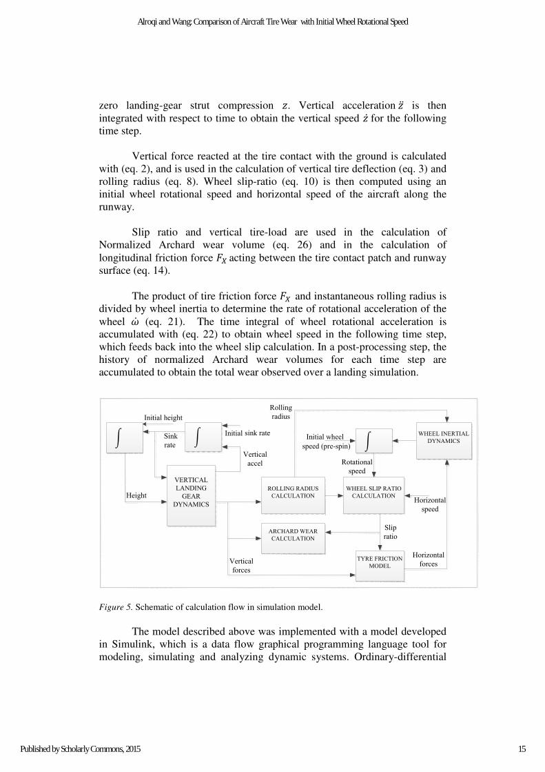
zero landing-gear strut compression . Vertical acceleration is then
integrated with respect to time to obtain the vertical speed for the following
time step.
Vertical force reacted at the tire contact with the ground is calculated
with (eq. 2), and is used in the calculation of vertical tire deflection (eq. 3) and
rolling radius (eq. 8). Wheel slip-ratio (eq. 10) is then computed using an
initial wheel rotational speed and horizontal speed of the aircraft along the
runway.
Slip ratio and vertical tire-load are used in the calculation of
Normalized Archard wear volume (eq. 26) and in the calculation of
longitudinal friction force �� acting between the tire contact patch and runway
surface (eq. 14).
The product of tire friction force �� and instantaneous rolling radius is
divided by wheel inertia to determine the rate of rotational acceleration of the
wheel Y (eq. 21). The time integral of wheel rotational acceleration is
accumulated with (eq. 22) to obtain wheel speed in the following time step,
which feeds back into the wheel slip calculation. In a post-processing step, the
history of normalized Archard wear volumes for each time step are
accumulated to obtain the total wear observed over a landing simulation.
TYRE FRICTION
MODEL
WHEEL SLIP RATIO
CALCULATION
ARCHARD WEAR
CALCULATION
WHEEL INERTIAL
DYNAMICS
ROLLING RADIUS
CALCULATION
VERTICAL
LANDING
GEAR
DYNAMICS
y ���� y ���� y ����
Horizontal
forcesVertical
forces
Horizontal
speed
Slip
ratio
Vertical
accel
sink rateInitial Sink
rate
Initial height
Height
Initial wheel
speed (pre-spin)
Rolling
radius
Rotational
speed
Figure 5. Schematic of calculation flow in simulation model.
The model described above was implemented with a model developed
in Simulink, which is a data flow graphical programming language tool for
modeling, simulating and analyzing dynamic systems. Ordinary-differential
15
Alroqi and Wang: Comparison of Aircraft Tire Wear with Initial Wheel Rotational Speed
Published by Scholarly Commons, 2015
equations in the model were solved using the Runge-Kutta Dormand-Prince
(RKDP) method. A variable time-step was allowed between limits of 1x10⁻⁶
and 1x10⁻³
seconds, where the time step is reduced automatically if absolute
and relative errors exceed a tolerance of 1x10⁻³
units.
The model was initiated with initial sink rate of 2 m/s and horizontal
speed of 75.6 m/s for baseline calculations, and later the initial sink rates and
vertical speeds where altered to allow the sensitivity of tire wear to initial
aircraft speed to be estimated. For each set of initial vertical and horizontal
aircraft speeds, a range of individual simulations were performed with various
initial wheel rotational speeds at touchdown, to investigate potential
improvements on tire wear from technologies that pre-spin an aircraft tire
before touchdown. Vehicle mass was set to 295,743 kg (Boeing, 2011) for the
simulations, with the vertical force on one tire being �� from (eq. 2).
Longitudinal tire force was initialized with a value of zero, and was
accumulated with the tire dynamics described by the LuGre model above.
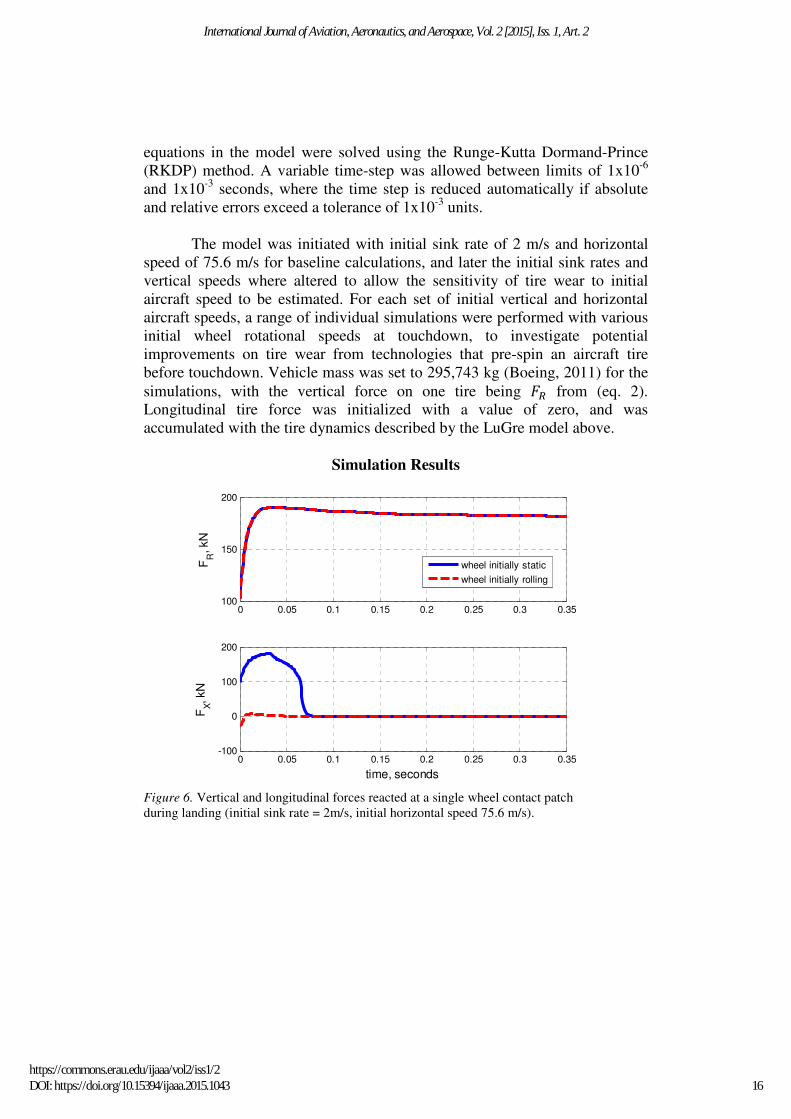
Simulation Results
Figure 6. Vertical and longitudinal forces reacted at a single wheel contact patch
during landing (initial sink rate = 2m/s, initial horizontal speed 75.6 m/s).
0 0.05 0.1 0.15 0.2 0.25 0.3 0.35100
150
200
FR
, kN
0 0.05 0.1 0.15 0.2 0.25 0.3 0.35-100
0
100
200
FX, kN
time, seconds
wheel initially static
wheel initially rolling
16
International Journal of Aviation, Aeronautics, and Aerospace, Vol. 2 [2015], Iss. 1, Art. 2
https://commons.erau.edu/ijaaa/vol2/iss1/2DOI: https://doi.org/10.15394/ijaaa.2015.1043
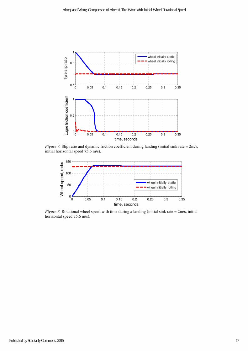
Figure 7. Slip ratio and dynamic friction coefficient during landing (initial sink rate = 2m/s,
initial horizontal speed 75.6 m/s).
Figure 8. Rotational wheel speed with time during a landing (initial sink rate = 2m/s, initial
horizontal speed 75.6 m/s).
0 0.05 0.1 0.15 0.2 0.25 0.3 0.35-0.5
0
0.5
1
Tyre
slip
ra
tio
0 0.05 0.1 0.15 0.2 0.25 0.3 0.350
0.5
1
Lu
gre
fri
ctio
n c
oe
ffic
ien
t
time, seconds
wheel initially static
wheel initially rolling
0 0.05 0.1 0.15 0.2 0.25 0.3 0.350
50
100
150
Wh
ee
l sp
ee
d, ra
d/s
time, seconds
wheel initially static
wheel initially rolling
17
Alroqi and Wang: Comparison of Aircraft Tire Wear with Initial Wheel Rotational Speed
Published by Scholarly Commons, 2015
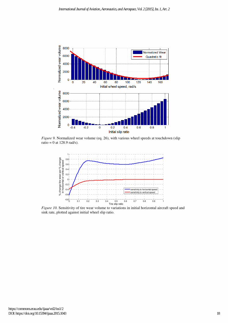
Figure 9. Normalized wear volume (eq. 26), with various wheel speeds at touchdown (slip
ratio = 0 at 128.9 rad/s).
Figure 10. Sensitivity of tire wear volume to variations in initial horizontal aircraft speed and
sink rate, plotted against initial wheel slip ratio.
0 0.1 0.2 0.3 0.4 0.5 0.6 0.7 0.8 0.9 1-0.8
-0.6
-0.4
-0.2
0
0.2
0.4
0.6
0.8
1
Tire slip ratio
% c
ha
ng
e tire
we
ar
pe
r %
ch
an
ge
in h
orizo
nta
l or
ve
rtic
al s
pe
ed
sensitivity to horizontal speed
sensitivity to vertical speed
18
International Journal of Aviation, Aeronautics, and Aerospace, Vol. 2 [2015], Iss. 1, Art. 2
https://commons.erau.edu/ijaaa/vol2/iss1/2DOI: https://doi.org/10.15394/ijaaa.2015.1043
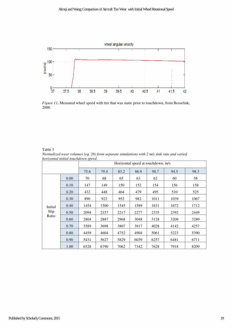
Figure 11. Measured wheel speed with tire that was static prior to touchdown, from Besselink,
2000.
Table 3
Normalized wear volumes (eq. 26) from separate simulations with 2 m/s sink rate and varied
horizontal initial touchdown speed.
Horizontal speed at touchdown, m/s
75.6 79.4 83.2 86.9 90.7 94.5 98.3
Initial
Slip
Ratio
0.00 70 68 65 63 62 60 58
0.10 147 149 150 152 154 156 158
0.20 432 448 464 479 495 510 525
0.30 890 922 952 982 1011 1039 1067
0.40 1454 1500 1545 1589 1631 1672 1712
0.50 2094 2157 2217 2277 2335 2392 2449
0.60 2804 2887 2968 3048 3128 3209 3289
0.70 3589 3698 3807 3917 4028 4142 4257
0.80 4459 4604 4752 4904 5061 5223 5390
0.90 5431 5627 5829 6039 6257 6481 6711
1.00 6528 6790 7062 7342 7628 7918 8209
19
Alroqi and Wang: Comparison of Aircraft Tire Wear with Initial Wheel Rotational Speed
Published by Scholarly Commons, 2015
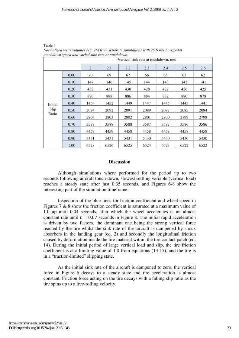
Table 4
Normalized wear volumes (eq. 26) from separate simulations with 75.6 m/s horizontal
touchdown speed and varied sink rate at touchdown.
Vertical sink rate at touchdown, m/s
2 2.1 2.2 2.3 2.4 2.5 2.6
Initial
Slip
Ratio
0.00 70 69 67 66 65 63 62
0.10 147 146 145 144 143 142 141
0.20 432 431 430 428 427 426 425
0.30 890 888 886 884 882 880 878
0.40 1454 1452 1449 1447 1445 1443 1441
0.50 2094 2092 2091 2089 2087 2085 2084
0.60 2804 2803 2802 2801 2800 2799 2798
0.70 3589 3588 3588 3587 3587 3586 3586
0.80 4459 4459 4458 4458 4458 4458 4458
0.90 5431 5431 5431 5430 5430 5430 5430
1.00 6528 6526 6525 6524 6523 6522 6522
Discussion
Although simulations where performed for the period up to two
seconds following aircraft touch-down, slowest settling variable (vertical load)
reaches a steady state after just 0.35 seconds, and Figures 6-8 show the
interesting part of the simulation timeframe.
Inspection of the blue lines for friction coefficient and wheel speed in
Figures 7 & 8 show the friction coefficient is saturated at a maximum value of
1.0 up until 0.04 seconds, after which the wheel accelerates at an almost
constant rate until � � 0.07 seconds in Figure 8. The initial rapid acceleration
is driven by two factors, the dominant one being the strong vertical force
reacted by the tire whilst the sink rate of the aircraft is dampened by shock
absorbers in the landing gear (eq. 2) and secondly the longitudinal friction
caused by deformation inside the tire material within the tire contact patch (eq.
14). During the initial period of large vertical load and slip, the tire friction
coefficient is at a limiting value of 1.0 from equations (13-15), and the tire is
in a “traction-limited” slipping state.
As the initial sink rate of the aircraft is dampened to zero, the vertical
force in Figure 6 decays to a steady state and tire acceleration is almost
constant. Friction force acting on the tire decays with a falling slip ratio as the
tire spins up to a free-rolling velocity.
20
International Journal of Aviation, Aeronautics, and Aerospace, Vol. 2 [2015], Iss. 1, Art. 2
https://commons.erau.edu/ijaaa/vol2/iss1/2DOI: https://doi.org/10.15394/ijaaa.2015.1043
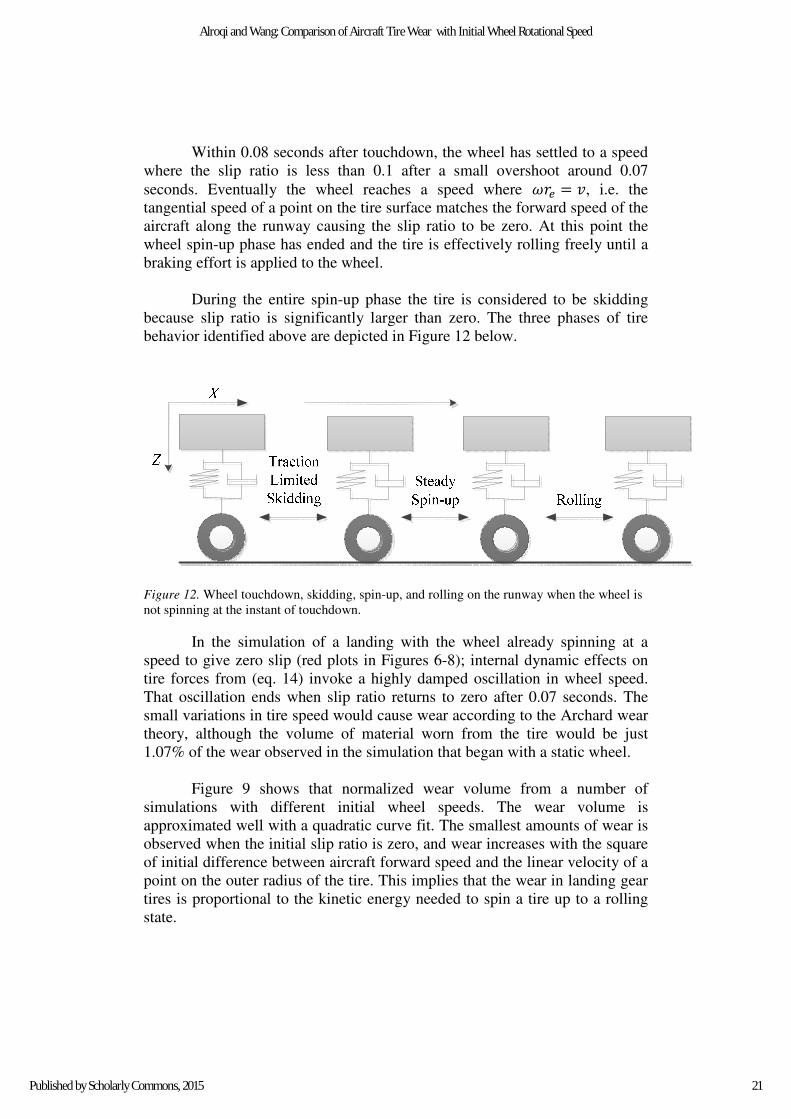
Within 0.08 seconds after touchdown, the wheel has settled to a speed
where the slip ratio is less than 0.1 after a small overshoot around 0.07
seconds. Eventually the wheel reaches a speed where Y�$ � �, i.e. the
tangential speed of a point on the tire surface matches the forward speed of the
aircraft along the runway causing the slip ratio to be zero. At this point the
wheel spin-up phase has ended and the tire is effectively rolling freely until a
braking effort is applied to the wheel.
During the entire spin-up phase the tire is considered to be skidding
because slip ratio is significantly larger than zero. The three phases of tire
behavior identified above are depicted in Figure 12 below.
Figure 12. Wheel touchdown, skidding, spin-up, and rolling on the runway when the wheel is
not spinning at the instant of touchdown.
In the simulation of a landing with the wheel already spinning at a
speed to give zero slip (red plots in Figures 6-8); internal dynamic effects on
tire forces from (eq. 14) invoke a highly damped oscillation in wheel speed.
That oscillation ends when slip ratio returns to zero after 0.07 seconds. The
small variations in tire speed would cause wear according to the Archard wear
theory, although the volume of material worn from the tire would be just
1.07% of the wear observed in the simulation that began with a static wheel.
Figure 9 shows that normalized wear volume from a number of
simulations with different initial wheel speeds. The wear volume is
approximated well with a quadratic curve fit. The smallest amounts of wear is
observed when the initial slip ratio is zero, and wear increases with the square
of initial difference between aircraft forward speed and the linear velocity of a
point on the outer radius of the tire. This implies that the wear in landing gear
tires is proportional to the kinetic energy needed to spin a tire up to a rolling
state.
21
Alroqi and Wang: Comparison of Aircraft Tire Wear with Initial Wheel Rotational Speed
Published by Scholarly Commons, 2015
Sensitivity analysis was performed by varying initial sink rate and
horizontal speed in 5% increments up to 30% larger than the base values of 2
m/s and 75.6 m/s respectively. Results from sensitivity analysis on the data in
tables 3 & 4 are shown in Figure 10, Tire wear is more sensitive to increases
in aircraft horizontal speed than it is sensitive to increases in the vertical sink
rate at touchdown. A one-percent increase in horizontal speed at touchdown is
expected to increase tire wear by between 0.59% and 0.83% at slip ratios
greater than 0.2. At lower initial slip ratios the sensitivity of tire wear to
horizontal landing speed reduces.
When the wheel is already spinning at the free-rolling speed, at an
initial slip ratio of zero, simulations showed tire wear actually reducing by
0.6% for every one-percent increase in landing speed, although the wear
volume at such slip ratios is already very small so change in wear volume at
zero slip in cubic metre s is practically negligible. Sensitivity to touchdown is
about zero for initial slip ratios of 0.6 and above, and nonzero although
practically negligible at lower slip ratios when a tangible measure of wear
volume is considered. Slightly negative values of tire wear sensitivity to sink
rate imply that heavier landings make the tire spin-up process more efficient,
with larger vertical forces increasing the spin-up torque compared to more
gentle touchdowns.
Figure 11 shows the tire speed with time from an experimental test
performed on a Boeing 747-400 aircraft from (Besselink, 2000). The spin-up
time of ~ 0.1 seconds corresponds well with our simulation, although the
oscillation in wheel speed seen in the data was not present in our simulation
results (Figure 8). It is expected that the flexible aircraft body is responsible
for variations in tire vertical loading after touchdown, which would vary the
friction force �� acting on the tire, and is a second-order effect not captured by
our lumped-mass vertical dynamics model.
Conclusions
A simulation model has been developed for comparing tire wear
between an initially non-spinning aircraft main-gear wheel and a wheel that is
already spinning at the instant of touchdown. A tire that is pre-spun to match
the forward speed of the aircraft prior to touchdown will typically experience
just 1.07% of the material removal from abrasive wear that would take place
on an un-spun tire.
Tire wear increases by less than per one-percent increase in aircraft
horizontal speed for un-spun tires. If a pre-spinning device is used to make the
touchdown wheel slip ratio smaller than 0.2, sensitivity to longitudinal speed
reduces. Tire wear is barely affected by touchdown sink rate in comparison to
variations in horizontal speed.
22
International Journal of Aviation, Aeronautics, and Aerospace, Vol. 2 [2015], Iss. 1, Art. 2
https://commons.erau.edu/ijaaa/vol2/iss1/2DOI: https://doi.org/10.15394/ijaaa.2015.1043
Simplification of the Archard wear (eq. 23) to a normalized wear
volume (eq. 26) allowed a relative comparison of tire wear between separate
simulations to be made, without the need for tire or runway material
properties. From simulating landings with a variety of initial wheel rotational
speeds, Archard wear theory predicts that the amount of material worn from
the tire on each landing is proportional to the square of the speed difference
between aircraft forward speed and the tangential speed of a point on the tire
tread at the instant of touchdown, i.e. the kinetic energy that the wheel must
gain in order to reach a free-rolling state with zero slip. If the wheel was pre-
spun to the free-rolling speed before the moment of touchdown, Archard wear
theory predicts that tire wear would be reduced and therefore tire life could be
improved significantly.
Future Work
The work performed in this study strongly suggests that a wheel spin-
up device can improve the life of heavy aircraft main landing gear tires.
Additional research should pursue the feasibility in terms of mechanical
complexity and financial costs and benefits of implementing pre-spinning
technologies on commercial aircraft. Simulation of the technologies
highlighted in the literature review would be useful in identifying the
characteristics of a pre-opening device that performs most effectively.
The Archard wear theory used to compare tire wear is a very simple
linear approximation, and it would be advisable to compare with more other
wear models to confirm the relative wear prediction from simulations between
un-spun and pre-spun tires.
Only longitudinal dynamics where included in the case study presented
in this paper. A further study could include the tire wear induced with initial
lateral slip as well as longitudinal slip for cross-wind landings, although
quantifying the distribution of crosswind component over a large number of
landing events would be difficult. The cosine component of tire forces in
crosswind landings would be interesting to add to the model, although it is
expected that the tire wear component from this would be small.
23
Alroqi and Wang: Comparison of Aircraft Tire Wear with Initial Wheel Rotational Speed
Published by Scholarly Commons, 2015
References
Andersson, S., Soderberg, A., & Bjorklund, S. (2007). Friction models for
sliding dry, boundary and mixed lubricated contacts. Elsevier:
Tribology International, 40(4), 580-587.
doi:10.1016/j.triboint.2005.11.014
Bartram, M., Mavros, G., & Biggs, S. (2010). A study on the effect of road
friction on driveline vibrations. Proceedings of the Institution of
Mechanical Engineers, Part K: Journal of Multi-body Dynamics,
224(4), 321-340. doi: 10.1243/14644193jmbd266
Beazley, R. H. (1947). Aircraft wheel spinner and control. U.S. Patent,
Publication No. US2414849 A. Washington, DC: U.S. Patent and
Trademark Office. Retrieved from
http://www.google.com/patents/US2414849
Besselink, I.J.M. (2000). Shimmy of aircraft main landing gears. Delft:
Technische Universiteit Delft. PhD thesis. Retrieved from
http://www.tue.nl/en/publication/ep/p/d/ep-uid/227775/
Boeing Commercial Airplane Co. (2011). Approach speeds for Boeing
airplanes. Retrieved from
http://www.boeing.com/assets/pdf/commercial/airports/faqs/
arcandapproachspeeds.pdf
Braghin, F. Cheli, F., Melzi, S., & Resta, F. (2006). Tire wear model:
validation and sensitivity analysis. Springer:Meccanica, 41(2)143-
156. doi: 10.1007/s11012-005-1058-9
Cadle, S.H. & Williams, R.L. (1978). Gas and particle emissions from
automobile tires in laboratory and field studies. Taylor & Francis:
Journal of the Air Pollution Control Association, 28(5), 502-507.
doi: 10.1080/00022470.1978.10470623
Canudas-de-Wit, C., Petersen, M. L., & Shiriaev, A. (2003). A new nonlinear
observer for tire/road distributed contact friction. 42nd IEEE
International Conference on Decision and Control (IEEE Cat.
No.03CH37475). doi: 10.1109/CDC.2003.1272952
Canudas-de-Wit, C., Tsiotras, P., Velenis, E., Basset, M. & Gissinger, G.
(2003). Dynamic friction models for road/tire longitudinal interaction.
Vehicle System, 39(3),189-226. doi: 10.1076/vesd.39.3.189.14152
24
International Journal of Aviation, Aeronautics, and Aerospace, Vol. 2 [2015], Iss. 1, Art. 2
https://commons.erau.edu/ijaaa/vol2/iss1/2DOI: https://doi.org/10.15394/ijaaa.2015.1043
Dahl, P. R. (1968). A solid friction model. The Aerospace Corporation.
Technical report. Los Angeles: Los Angeles Air Force Station.
Retrieved from www.dtic.mil/dtic/tr/fulltext/u2/a041920.pdf
Daidzic, N. E., & Shrestha, J. (2008). Airplane landing performance on
contaminated runways in adverse conditions. Journal of Aircraft
45(6), 2131-2144. doi: 10.2514/1.38056
Daugherty, R. H. (2003). A study of the mechanical properties of modern
radial aircraft tires. Retrieved from
http://citeseerx.ist.psu.edu/viewdoc/download?doi=10.1.1.74.1702&r
p=re&type=pdf
Day, A. J. (2014). Braking of road vehicles. Portsmouth, UK: Butterworth
Heinemann.
De, S. K., & White, J. R. (Eds.), (2001). Rubber technologist's handbook.,
Shrewsbury, UK: ISmithers Rapra Publishing.
ESDU 71025. (1995). Frictional and retarding forces on aircraft tyres. Part I:
introduction. The Royal Aeronautical Society, 1971 amended 1995.
London: IHS Inc.
FAA. (2004). Airplane Flying Handbook. FAA Handbooks series. US
Department of Transportation, Federal Aviation Administration.
Washington, DC: Author.
Goodyear. (2002). Aircraft data tire book. Akron, OH: The Goodyear Tire &
Rubber Co.
Hamza, S. (2014). Sensitivity analysis of tire model micro-coefficients.
MascotNum Annual Conference, ETH Zurich (Switzerland). Retrieved
from http://www.ibk.ethz.ch/su/mascotnum2014/PhDStudentsDay/
PhDAbstracts MN14_-_Hamza.pdf
Horvath, V. & Szoke, B. B. (2006). Airplane tire saver by protrusion air
foils. World Intellectual Property Organization. Patent, Publication
No. WO/2006/130944.
Hunter, J. R. (1997). Simple things won't save the Earth. Austin, TX:
University of Texas Press.
25
Alroqi and Wang: Comparison of Aircraft Tire Wear with Initial Wheel Rotational Speed
Published by Scholarly Commons, 2015
Jingzhe, J. (2007). A mixed mode function – Boundary element method for
very large floating structure – Water interaction systems excited by
airplane landing impacts. Doctoral thesis, Southampton University.
Khal, S., & Khal, A. (2013). Apparatus for pre-rotating aircraft tires. U.S.
Patent, Publication No. US20130112809A1.
Khapane, P. D. (2004). Simulation of aircraft landing gear dynamics using
flexible multibody dynamics methods in SIMPACK. Conference:
ICAS, Yokohama, Japan. Retrieved from
http://icas.org/ICAS_ARCHIVE/ICAS2004/PAPERS/262.PDF
Lernbeiss, R. (2004). Simulation of the dynamic behavior of an aircraft
landing gear during landing. Simpack User Meeting, Vienna
University of Technology. Retrieved from
http://www.simpack.com/fileadmin/simpack/doc/usermeeting04/
um04_tu-wien-lernb.pdf
Li, F. & Jiao, Z. (2013). Robust control for aircraft anti-skid braking system
based on dynamic tire/road friction force model. Proceedings of the
2nd International Conference on Computer Science and Electronics
Engineering (ICCSEE). doi:10.2991/iccsee.2013.409
Li, Y., Zhang, J., & Guan, X. (2012). Estimation of vehicle parameters and
road friction using steering torque and wheel speeds. WSEAS
Transactions on Systems. Retrieved from
http://www.wseas.org/multimedia/journals/systems/2012/54-561.pdf
Lindsley, N. J., & Talekar, N. B. (2000). A tire model for air vehicle landing
gear dynamics. International ADAMS User Conference. Retrieved
from http://web.mscsoftware.com/support/library/conf/
adams/na/2000/18_usaf_tire_landing_gear.pdf
Lufthansa Technik. (n.d.). Aircraft tires: more than just rubber on steel.
Retrieved from http://www.lufthansa-technik.com/aircraft-tires
Lupker, H.A, Montanaro, F., Donadio, D., Gelosa, E., & Vis, M.A. (2002).
Truck tire wear assessment and prediction. 7th International
Symposium on Heavy Vehicle Weights & Dimensions, Delft, The
Netherlands. Retrieved from http://road-transport-technology.org/
Proceedings/7%20%20ISHVWD/Truck%20Tyre%20Wear%20
Assessment%20And%20Predicion%20-%20L%20upker.pdf
Mair, A. W., & Birdsall, D. L. (1992). Aircraft performance. Cambridge, UK:
Cambridge University Press.
26
International Journal of Aviation, Aeronautics, and Aerospace, Vol. 2 [2015], Iss. 1, Art. 2
https://commons.erau.edu/ijaaa/vol2/iss1/2DOI: https://doi.org/10.15394/ijaaa.2015.1043
Milwitzky, B., Lindquist, D. C., & Potter, D. M. (1955). An experimental
study of applied ground loads in landing. National advisory committee
for aeronautics, Langley aeronautical laboratory, Washington,
DC. Retrieved from http://hdl.handle.net/2060/19930092250
Ochi, Y., & Kanai, K. (1999). Automatic approach and landing for propulsion
controlled aircraft by H∞ control. Proceedings of the 1999 IEEE
International Conference on Control Applications (Cat.
No.99CH36328). vol.2, pp.997-1002. doi: 10.1109/CCA.1999.800951
Padovan, J., Kazempour, A., & Kim, Y. H. (1990). Aircraft landing-induced
tire spinup. Journal of Aircraft, 28(12), 849-854.
doi: 10.2514/3.46108
Persson, B. (2006). Rubber friction: role of the flash temperature. Journal of
Physics: Condensed Matter, 18(32), 7789-7823.
doi: 10.1088/0953-8984/18/32/025
Saibel, E., & Tsai, C. (1969). Tire wear model. Interim Report, Issue 2.
Carnegie Mellon University. New York: Clearing house.
Slagmaat, V. M.T.P. (1992). Tire models in aircraft landing gear simulation.
VehicleSystem Dynamics, 21(sup001), 108-115.
doi: 10.1080/00423119208970002
Tanyolac, T. & Yasarcan, H. (2011). A soft landing model and a mass
spring damper based control heuristic. Proceedings of The 29th
International System Dynamics Conference. Retrieved from
http://www.systemdynamics.org/conferences/2011/proceed/papers/P11
19.pdf
Tomita, H. (1964). Friction coefficients between tires and pavements
surfaces. Naval Civil Engineering Lab Port Hueneme Calif. Retrieved
from http://www.dtic.mil/cgibin/GetTRDoc?AD=AD0705987
Tong, G., & Jin, X. (2012). Study on the simulation of radial tire wear
Characteristics. WSEAS Transaction on Systems, 11(8), 419-429.
Retrieved from http://www.wseas.org/multimedia/journals/
systems/2012/56-433.pdf
Tong, G., Wang, Q., & Jin, X. (2012). Adaptive lane keeping control of
vehicles with tire influence. International journal of Advancements in
Computing Technology, 4(18), 433-440.
doi:10.4156/ijact.vol4.issue18.51
27
Alroqi and Wang: Comparison of Aircraft Tire Wear with Initial Wheel Rotational Speed
Published by Scholarly Commons, 2015
United States Air Force (2007). Republic F-84 Thunderjet pilot's flight
operating manual. Los Angeles: Periscope Film.
Wojewoda, J., Stefanski, A., Wiercigroch, M., & Kapitaniak, T. (2008).
Hysteretic effects of dry friction: modelling and experimental studies.
Philosophical Transactions of the Royal Society A: Mathematical,
Physical and Engineering Sciences, 366(1866), 747-765.
doi:10.1098/rsta.2007.2125
Zglimbea, R., Finca, V., Greaban, E., & Constantin, M. (2009). Research on
parameter identification of modified friction LuGre Model based
distributions theory. WSEAS Transactions on Systems, 8(8), 978-987.
Retrieved from http://www.wseas.us/e-library/transactions/systems/
2009/29-647.pdf
Zhang, Y., Zhang, G., & Yu, F. (2012). Modeling and µ synthesis control of
vehicle active suspension with motor actuator. WSEAS Transactions
on Systems, 11(5), 173-186. Retrieved from
http://www.wseas.org/multimedia/journals/systems/2012/55-235.pdf
28
International Journal of Aviation, Aeronautics, and Aerospace, Vol. 2 [2015], Iss. 1, Art. 2
https://commons.erau.edu/ijaaa/vol2/iss1/2DOI: https://doi.org/10.15394/ijaaa.2015.1043