Embed Size (px)
Citation preview
Hydrol. Earth Syst. Sci., 14, 729–750, 2010www.hydrol-earth-syst-sci.net/14/729/2010/doi:10.5194/hess-14-729-2010© Author(s) 2010. CC Attribution 3.0 License.
Hydrology andEarth System
Sciences
Comparison of algorithms and parameterisations for infiltrationinto organic-covered permafrost soils
Y. Zhang1, S. K. Carey1, W. L. Quinton 2, J. R. Janowicz3, J. W. Pomeroy4, and G. N. Flerchinger5
1Dept. of Geography and Environmental Studies, Carleton University, Ottawa, Canada2Cold Regions Research Centre, Wilfrid Laurier University, Waterloo, Canada3Environmental Programs Branch, Yukon Department of Environment, Whitehorse, Canada4Centre for Hydrology, University of Saskatchewan, Saskatoon, Canada5Northwest Watershed Research Center, USDA Agricultural Research Service, Boise, USA
Received: 11 August 2009 – Published in Hydrol. Earth Syst. Sci. Discuss.: 4 September 2009Revised: 6 April 2010 – Accepted: 3 May 2010 – Published: 11 May 2010
Abstract. Infiltration into frozen and unfrozen soils is crit-ical in hydrology, controlling active layer soil water dy-namics and influencing runoff. Few Land Surface Models(LSMs) and Hydrological Models (HMs) have been devel-oped, adapted or tested for frozen conditions and permafrostsoils. Considering the vast geographical area influenced byfreeze/thaw processes and permafrost, and the rapid environ-mental change observed worldwide in these regions, a needexists to improve models to better represent their hydrology.
In this study, various infiltration algorithms and parameter-isation methods, which are commonly employed in currentLSMs and HMs were tested against detailed measurements atthree sites in Canada’s discontinuous permafrost region withorganic soil depths ranging from 0.02 to 3 m. Field data fromtwo consecutive years were used to calibrate and evaluate theinfiltration algorithms and parameterisations. Important con-clusions include: (1) the single most important factor thatcontrols the infiltration at permafrost sites is ground thawdepth, (2) differences among the simulated infiltration bydifferent algorithms and parameterisations were only foundwhen the ground was frozen or during the initial fast thawingstages, but not after ground thaw reaches a critical depth of15 to 30 cm, (3) despite similarities in simulated total infiltra-tion after ground thaw reaches the critical depth, the choiceof algorithm influenced the distribution of water among thesoil layers, and (4) the ice impedance factor for hydraulicconductivity, which is commonly used in LSMs and HMs,may not be necessary once the water potential driven frozen
Correspondence to:Y. Zhang([email protected])
soil parameterisation is employed. Results from this workprovide guidelines that can be directly implemented in LSMsand HMs to improve their application in organic covered per-mafrost soils.
1 Introduction
Infiltration of snowmelt or rain into frozen ground or theunfrozen active layer is a critical hydrological process inpermafrost regions (Woo, 1986) and its simulation is a keycomponent in almost all process-based Land Surface Mod-els (LSMs) (e.g. Bonan, 1991; Verseghy, 1991; Desbor-ough and Pitman, 1998; Gusev and Nasonova, 2003; Daiet al., 2003) and Hydrological Models (HMs) (e.g. Bevenand Kirkby, 1979; Liang et al., 1994; Yang and Niu, 2003;Pomeroy et al., 2007; Peckham, 2008). However, math-ematically quantifying infiltration has always been a chal-lenge (Smith et al., 2002), due mainly to the heterogeneityof most natural soils and highly dynamic changes of soil wa-ter status and hydraulic properties during infiltration. Thosedifficulties become extreme in permafrost environments dueto ground thawing/freezing processes and a surface organiclayer that frequently mantles permafrost terrain (Kane andStein, 1983; Kane and Chacho, 1990; Slater et al., 1998).Soil hydraulic properties change rapidly during infiltrationor abruptly within infiltration depth between: (1) frozen andunfrozen states (Burt and Williams, 1976; Kane and Stein,1983), (2) saturated and unsaturated conditions (Dingman,2002; Carey et al., 2007), (3) organic and mineral soils(Carey and Woo, 2001; Quinton et al., 2008) and (4) eventhe upper and lower layers of organic soil (Slaughter and
Published by Copernicus Publications on behalf of the European Geosciences Union.
730 Y. Zhang et al.: Cold region infiltration algorithms
Kane, 1979; Quinton et al., 2005), which may cause con-vergence problems for numerical infiltration schemes (e.g.Zhao et al., 1997) or violate the assumptions for many an-alytical infiltration schemes (e.g. Green and Ampt, 1911).Other complicating factors for infiltration in permafrost ter-rain include macropore-induced preferential flow (Mackay,1983), ineffective pore spaces in organic soils (Quinton etal., 2008), and hysteresis effects during thawing and freezing(Horiguchi and Miller, 1980). Mathematical representationof infiltration into permafrost soils is poorly developed com-pared to those in non-permafrost soils (Kane and Chacho,1990; Luo et al., 2003).
Most early LSMs and HMs do not have an explicit frozensoil scheme (Luo et al., 2003; Zhang et al., 2008). Theinfluence of frozen soil on infiltration and runoff is typi-cally treated with a few simple assumptions such as: (1) liq-uid soil moisture remains at zero or a small constant valueonce the soil temperature passes below 0◦C (e.g. Verseghy.,1991; Dai et al., 2003), and (2) hydraulic conductivity be-comes zero once frozen (e.g. Bonan, 1991; Verseghy, 1991;Dai et al., 2003). Recent improvements of frozen soil pro-cesses in LSMs and HMs include: (1) soil ice content is ex-plicitly represented as a diagnostic variable (e.g. Cherkaueret al., 2003; Niu and Yang, 2006; Nicolsky et al., 2007),(2) thawing/freezing depth is recognized as a controlling fac-tor for infiltration/runoff and is dynamically simulated withimproved algorithms, parameterisations and model configu-rations (e.g. Slater et al., 1998; Kuchment et al., 2000; Yiet al., 2006; Zhang et al., 2008), (3) variable unfrozen watercontent is parameterized using relationships with subfreez-ing soil temperature (e.g. Li and Koike, 2003; Zhang et al.,2008), and (4) frozen soil infiltration is allowed based uponsoil ice content or subfreezing soil temperature (Niu andYang, 2006; Nicolsky et al., 2007; Pomeroy et al., 2007).In some cold region hydrological models (e.g. Flerchingerand Saxton, 1989; Zhao and Gray, 1997; Zhang et al., 2000;Pomeroy et al., 2007), infiltration schemes for frozen soilhave been explicitly designed. However, their algorithmsvary widely from first order empirical estimation (e.g. Grayet al., 1985) to complex numerical solutions of the simul-taneously coupled thermal and moisture transfer equationswith phase changes (e.g. Tao and Gray, 1994; Zhao et al.,1997). Some models even provide multiple options for in-filtration simulations during different infiltration stages ordifferent site conditions (e.g. Pomeroy et al., 2007; Peck-ham, 2008). Testing and comparison of infiltration schemeswere only found for mineral soil conditions (e.g. Slater et al.,1998; Cherkauer and Lettenmaier, 1999; Cherkauer et al.,2003; Niu et al., 2005), and many of them only dealt withhomogeneous soils (e.g. Flerchinger et al., 1988; Zhao et al.,1997; Boike et al., 1998; Mishra et al., 2003; Chahinian etal., 2005). The validation of infiltration simulations in or-ganic covered permafrost soils is extremely scarce due to thelimited quantity and quality of field data in such regions.
In this study, we present a comprehensive review of infil-tration algorithms and parameterisations and evaluate theirapplicability for organic-covered permafrost soils. Selectedalgorithms and parameterisations are evaluated using fielddata obtained from three organic-covered sites in Canada’sdiscontinuous permafrost region. The overall objective is toprovide guidelines for the implementation of appropriate in-filtration algorithms/parameterisations in LSMs and HMs toimprove their performance in permafrost regions.
2 Review of infiltration algorithms andparameterisations
2.1 Infiltration algorithms
Infiltration of surface water is controlled by many factors,including soil depth and its texture profile, soil hydraulicproperties and water status, water supply intensity and pat-terns, infiltration time, and thawing/freezing depth. Effortshave been made to numerically solve the water transfer equa-tion or its coupled form with the heat transfer equation fornon-uniform unfrozen soil infiltration (e.g. Celia et al., 1990;Ross, 1990;Simunek et al., 2005), or uniform frozen soil in-filtration (e.g. Harlan, 1973; Guymon and Luthin, 1974; Taoand Gray, 1994; Zhao et al., 1997; Hansson et al., 2004), butto the best of our knowledge, no successful application ex-ists for infiltration problems in non-uniform soil with thaw-ing/freezing process involved. Moreover, since most of theinfiltration events in cold environments involve large vol-umes of water flux in a short period, extremely fine resolu-tions in temporal (seconds or less) and in spatial (centimetersor less) domains are required to achieve stable numerical so-lutions (Jame and Norum, 1980; Tao and Gray, 1994; Zhao etal., 1997; Smith et al., 2002), imposing considerable compu-tational expense. Consequently, operational LSMs and HMsrarely utilize numerical schemes for infiltration. Typically,infiltration is separately calculated using conceptual, empir-ical or analytical methods and added as a source term tothe numerical scheme, which is used to calculate the heattransfer and water redistribution within the vadose zone (e.g.SHAW, Flerchinger and Saxton, 1989; CLASS, Verseghy,1991; CLM3.5, Oleson et al., 2008). Considering this, nu-merical infiltration schemes are excluded from this study.
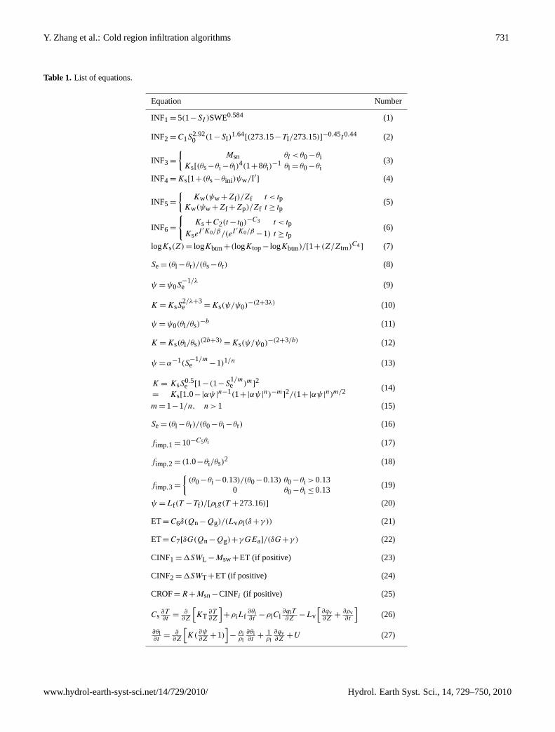
Table 1 lists equations of infiltration algorithms and pa-rameterisations referenced in this study. Table 2 summarisesmost infiltration schemes in current LSMs and HMs thatare applicable for soils involving thawing/freezing. Theconceptual models are typically developed for extreme soilconditions. For example, examining snowmelt infiltrationin frozen prairie soils, Granger et al. (1984) and Gray etal. (1985) grouped infiltration patterns into three broad cat-egories: (1) restricted; for soils with impermeable surfacelayers such as ice lenses, (2) unlimited; for soils with a highpercentage of air-filled macropores, and (3) limited; for soils
Hydrol. Earth Syst. Sci., 14, 729–750, 2010 www.hydrol-earth-syst-sci.net/14/729/2010/
Y. Zhang et al.: Cold region infiltration algorithms 731
Table 1. List of equations.
Equation Number
INF1 = 5(1−SI )SWE0.584 (1)
INF2 =C1S2.920 (1−SI)
1.64[(273.15−TI/273.15)]−0.45t0.44 (2)
INF3 =
{Msn θl <θ0−θi
Ks[(θs−θi −θl)4(1+8θi)
−1 θl = θ0−θi(3)
INF4 =Ks[1+(θs−θini)ψw/I′] (4)
INF5 =
{Kw(ψw +Zf)/Zf t < tp
Kw(ψw +Zf +Zp)/Zf t ≥ tp(5)
INF6 =
{Ks+C2(t− t0)
−C3 t < tp
KseI ′K0/β/(eI
′K0/β−1) t ≥ tp(6)
logKs(Z)= logKbtm+(logKtop− logKbtm)/[1+(Z/Ztrn)C4] (7)
Se= (θl −θr)/(θs−θr) (8)
ψ =ψ0S−1/λe (9)
K =KsS2/λ+3e =Ks(ψ/ψ0)
−(2+3λ) (10)
ψ =ψ0(θl/θs)−b (11)
K =Ks(θl/θs)(2b+3)
=Ks(ψ/ψ0)−(2+3/b) (12)
ψ =α−1(S−1/me −1)1/n (13)
K = KsS0.5e [1−(1−S
1/me )m]
2
= Ks[1.0−|αψ |n−1(1+|αψ |
n)−m]2/(1+|αψ |
n)m/2(14)
m= 1−1/n, n> 1 (15)
Se= (θl −θr)/(θ0−θi −θr) (16)
fimp,1 = 10−C5θi (17)
fimp,2 = (1.0−θi/θs)2 (18)
fimp,3 =
{(θ0−θi −0.13)/(θ0−0.13) θ0−θi >0.13
0 θ0−θi ≤ 0.13(19)
ψ =Lf(T −Tf)/[ρlg(T +273.16)] (20)
ET=C6δ(Qn−Qg)/(Lvρl(δ+γ )) (21)
ET=C7[δG(Qn−Qg)+γGEa]/(δG+γ ) (22)
CINF1 =1SWL −Msw+ET (if positive) (23)
CINF2 =1SWT +ET (if positive) (24)
CROF=R+Msn−CINFi (if positive) (25)
Cs∂T∂t
=∂∂Z
[KT
∂T∂Z
]+ρiLf
∂θi∂t
−ρlCl∂qlT∂Z
−Lv
[∂qv∂Z
+∂ρv∂t
](26)
∂θl∂t
=∂∂Z
[K(
∂ψ∂Z
+1)]−ρiρl
∂θi∂t
+1ρl
∂qv∂Z
+U (27)
www.hydrol-earth-syst-sci.net/14/729/2010/ Hydrol. Earth Syst. Sci., 14, 729–750, 2010
732 Y. Zhang et al.: Cold region infiltration algorithms
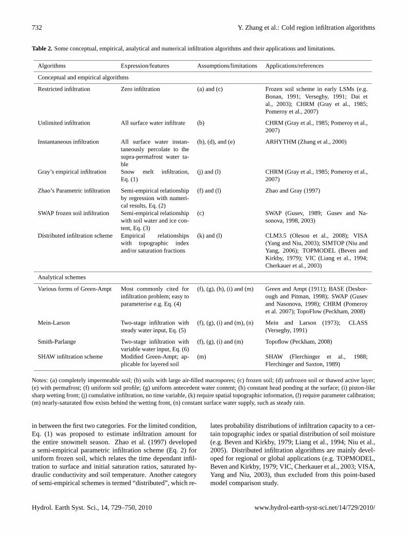
Table 2. Some conceptual, empirical, analytical and numerical infiltration algorithms and their applications and limitations.
Algorithms Expression/features Assumptions/limitations Applications/references
Conceptual and empirical algorithms
Restricted infiltration Zero infiltration (a) and (c) Frozen soil scheme in early LSMs (e.g.Bonan, 1991; Verseghy, 1991; Dai etal., 2003); CHRM (Gray et al., 1985;Pomeroy et al., 2007)
Unlimited infiltration All surface water infiltrate (b) CHRM (Gray et al., 1985; Pomeroy et al.,2007)
Instantaneous infiltration All surface water instan-taneously percolate to thesupra-permafrost water ta-ble
(b), (d), and (e) ARHYTHM (Zhang et al., 2000)
Gray’s empirical infiltration Snow melt infiltration,Eq. (1)
(j) and (l) CHRM (Gray et al., 1985; Pomeroy et al.,2007)
Zhao’s Parametric infiltration Semi-empirical relationshipby regression with numeri-cal results, Eq. (2)
(f) and (l) Zhao and Gray (1997)
SWAP frozen soil infiltration Semi-empirical relationshipwith soil water and ice con-tent, Eq. (3)
(c) SWAP (Gusev, 1989; Gusev and Na-sonova, 1998, 2003)
Distributed infiltration scheme Empirical relationshipswith topographic indexand/or saturation fractions
(k) and (l) CLM3.5 (Oleson et al., 2008); VISA(Yang and Niu, 2003); SIMTOP (Niu andYang, 2006); TOPMODEL (Beven andKirkby, 1979); VIC (Liang et al., 1994;Cherkauer et al., 2003)
Analytical schemes
Various forms of Green-Ampt Most commonly cited forinfiltration problem; easy toparameterise e.g. Eq. (4)
(f), (g), (h), (i) and (m) Green and Ampt (1911); BASE (Desbor-ough and Pitman, 1998); SWAP (Gusevand Nasonova, 1998); CHRM (Pomeroyet al. 2007); TopoFlow (Peckham, 2008)
Mein-Larson Two-stage infiltration withsteady water input, Eq. (5)
(f), (g), (i) and (m), (n) Mein and Larson (1973); CLASS(Verseghy, 1991)
Smith-Parlange Two-stage infiltration withvariable water input, Eq. (6)
(f), (g), (i) and (m) Topoflow (Peckham, 2008)
SHAW infiltration scheme Modified Green-Ampt; ap-plicable for layered soil
(m) SHAW (Flerchinger et al., 1988;Flerchinger and Saxton, 1989)
Notes: (a) completely impermeable soil; (b) soils with large air-filled macropores; (c) frozen soil; (d) unfrozen soil or thawed active layer;(e) with permafrost; (f) uniform soil profile; (g) uniform antecedent water content; (h) constant head ponding at the surface; (i) piston-likesharp wetting front; (j) cumulative infiltration, no time variable, (k) require spatial topographic information, (l) require parameter calibration;(m) nearly-saturated flow exists behind the wetting front, (n) constant surface water supply, such as steady rain.
in between the first two categories. For the limited condition,Eq. (1) was proposed to estimate infiltration amount forthe entire snowmelt season. Zhao et al. (1997) developeda semi-empirical parametric infiltration scheme (Eq. 2) foruniform frozen soil, which relates the time dependant infil-tration to surface and initial saturation ratios, saturated hy-draulic conductivity and soil temperature. Another categoryof semi-empirical schemes is termed “distributed”, which re-
lates probability distributions of infiltration capacity to a cer-tain topographic index or spatial distribution of soil moisture(e.g. Beven and Kirkby, 1979; Liang et al., 1994; Niu et al.,2005). Distributed infiltration algorithms are mainly devel-oped for regional or global applications (e.g. TOPMODEL,Beven and Kirkby, 1979; VIC, Cherkauer et al., 2003; VISA,Yang and Niu, 2003), thus excluded from this point-basedmodel comparison study.
Hydrol. Earth Syst. Sci., 14, 729–750, 2010 www.hydrol-earth-syst-sci.net/14/729/2010/
Y. Zhang et al.: Cold region infiltration algorithms 733
Analytical algorithms are exact solutions of the watertransfer equation (e.g. Richards’ equation) under specific soilconditions and water supply patterns. Despite their lim-iting assumptions (Table 2), analytical algorithms are themost frequently employed algorithms in LSMs and HMs,due to their solid physical base and ability to obtain pa-rameters through field measurements, texture associations(Clapp and Hornberger, 1978) or pedo-transfer functions(Wosten, 1999; Wagner et al., 2001). The most frequentlycited Green and Ampt (1911) algorithm (Eq. 4) has the fol-lowing assumptions: (1) uniform soil extending to half in-finite plane, (2) uniform antecedent water content, (3) con-stant head ponding at the surface, and (4) a piston-like sharpwetting front. Among the numerous efforts (e.g. Bouwer,1969; Smith et al., 2002; Chu and Marino, 2005; Talbotand Ogden, 2008) in relaxing these assumptions, the two-stage Mein and Larson (1973) infiltration scheme simulatesboth the pre-ponding and ponded infiltration of steady raininto uniform soil (Eq. 5), while the two-stage Smith and Par-lange (1978) scheme allows for variable rainfall rates (Eq. 6).Flerchinger et al. (1988) modified Green and Ampt algorithmto simulate infiltration into layered non-uniform soil and em-ployed it in the Simultaneous Heat and Water (SHAW) model(Flerchinger and Saxton, 1989).
2.2 Essential parameters for simulating infiltration
Practically all of the parameters in Eqs. (1–6) can be de-termined from basic soil hydraulic properties (i.e.θs, Ks,ψ0) and characteristics (i.e. relationships among water po-tential, water content and hydraulic conductivity). In thecontext of LSMs and HMs, basic hydraulic properties andcharacteristics are typically associated with texture classes(e.g. Clapp and Hornberger, 1978; Letts et al., 2000) or othersoil attributes such as bulk density or grain-size fraction (e.g.Wosten, 1999; Wagner et al., 2001). For frozen soils, param-eterisations of unfrozen water content and ice impedance tohydraulic conductivity are also crucial to infiltration simula-tion (Kane and Stein, 1983; Kane and Chacho, 1990; Slateret al., 1998; Quinton et al., 2008).
2.2.1 Soil hydraulic properties
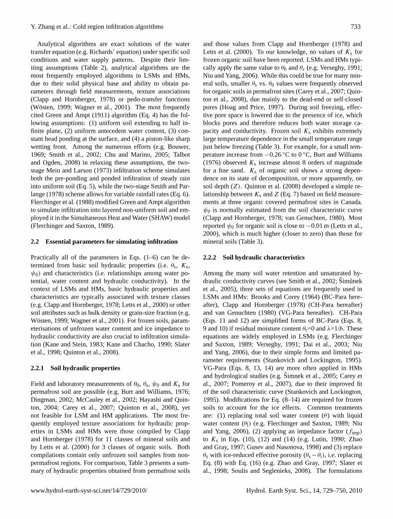
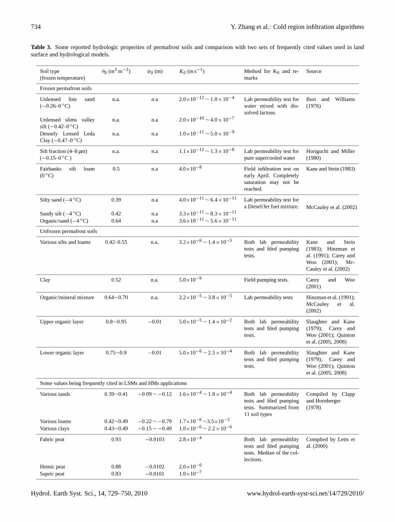
Field and laboratory measurements ofθ0, θs, ψ0 andKs forpermafrost soil are possible (e.g. Burt and Williams, 1976;Dingman, 2002; McCauley et al., 2002; Hayashi and Quin-ton, 2004; Carey et al., 2007; Quinton et al., 2008), yetnot feasible for LSM and HM applications. The most fre-quently employed texture associations for hydraulic prop-erties in LSMs and HMs were those compiled by Clappand Hornberger (1978) for 11 classes of mineral soils andby Letts et al. (2000) for 3 classes of organic soils. Bothcompilations contain only unfrozen soil samples from non-permafrost regions. For comparison, Table 3 presents a sum-mary of hydraulic properties obtained from permafrost soils
and those values from Clapp and Hornberger (1978) andLetts et al. (2000). To our knowledge, no values ofKs forfrozen organic soil have been reported. LSMs and HMs typi-cally apply the same value toθ0 andθs (e.g. Verseghy, 1991;Niu and Yang, 2006). While this could be true for many min-eral soils, smallerθs vs. θ0 values were frequently observedfor organic soils in permafrost sites (Carey et al., 2007; Quin-ton et al., 2008), due mainly to the dead-end or self-closedpores (Hoag and Price, 1997). During soil freezing, effec-tive pore space is lowered due to the presence of ice, whichblocks pores and therefore reduces both water storage ca-pacity and conductivity. Frozen soilKs exhibits extremelylarge temperature dependence in the small temperature rangejust below freezing (Table 3). For example, for a small tem-perature increase from−0.26◦C to 0◦C, Burt and Williams(1976) observedKs increase almost 8 orders of magnitudefor a fine sand.Ks of organic soil shows a strong depen-dence on its state of decomposition, or more apparently, onsoil depth (Z). Quinton et al. (2008) developed a simple re-lationship betweenKs andZ (Eq. 7) based on field measure-ments at three organic covered permafrost sites in Canada.ψ0 is normally estimated from the soil characteristic curve(Clapp and Hornberger, 1978; van Genuchten, 1980). Mostreportedψ0 for organic soil is close to−0.01 m (Letts et al.,2000), which is much higher (closer to zero) than those formineral soils (Table 3).
2.2.2 Soil hydraulic characteristics
Among the many soil water retention and unsaturated hy-draulic conductivity curves (see Smith et al., 2002;Simuneket al., 2005), three sets of equations are frequently used inLSMs and HMs: Brooks and Corey (1964) (BC-Para here-after), Clapp and Hornberger (1978) (CH-Para hereafter)and van Genuchten (1980) (VG-Para hereafter). CH-Para(Eqs. 11 and 12) are simplified forms of BC-Para (Eqs. 8,9 and 10) if residual moisture contentθr=0 andλ=1/b. Theseequations are widely employed in LSMs (e.g. Flerchingerand Saxton, 1989; Verseghy, 1991; Dai et al., 2003; Niuand Yang, 2006), due to their simple forms and limited pa-rameter requirements (Stankovich and Lockington, 1995).VG-Para (Eqs. 8, 13, 14) are more often applied in HMsand hydrological studies (e.g.Simnek et al., 2005; Carey etal., 2007; Pomeroy et al., 2007), due to their improved fitof the soil characteristic curve (Stankovich and Lockington,1995). Modifications for Eq. (8–14) are required for frozensoils to account for the ice effects. Common treatmentsare: (1) replacing total soil water content (θ ) with liquidwater content (θl) (e.g. Flerchinger and Saxton, 1989; Niuand Yang, 2006), (2) applying an impedance factor (fimp)
to Ks in Eqs. (10), (12) and (14) (e.g. Lutin, 1990; Zhaoand Gray, 1997; Gusev and Nasonova, 1998) and (3) replaceθs with ice-reduced effective porosity (θs−θi), i.e. replacingEq. (8) with Eq. (16) (e.g. Zhao and Gray, 1997; Slater etal., 1998; Soulis and Seglenieks, 2008). The formulations
www.hydrol-earth-syst-sci.net/14/729/2010/ Hydrol. Earth Syst. Sci., 14, 729–750, 2010
734 Y. Zhang et al.: Cold region infiltration algorithms
Table 3. Some reported hydrologic properties of permafrost soils and comparison with two sets of frequently cited values used in landsurface and hydrological models.
Soil type(frozen temperature)
θ0 (m3 m−3) ψ0 (m) K0 (m s−1) Method for K0 and re-marks
Source
Frozen permafrost soils
Unlensed fine sand(−0.26–0◦C)
n.a. n.a 2.0×10⁻¹²∼ 1.0×10⁻⁴ Lab permeability test for
water mixed with dis-solved lactose.
Burt and Williams(1976)
Unlensed slims valleysilt (−0.42–0◦C)
n.a. n.a 2.0×10⁻¹⁰∼ 4.0×10⁻⁷
Densely Lensed LedaClay (−0.47–0◦C)
n.a. n.a 1.0×10⁻¹¹∼ 5.0×10⁻⁹
Silt fraction (4–8 µm)(−0.15–0◦C )
n.a. n.a 1.1×10⁻¹²∼ 1.3×10⁻⁸ Lab permeability test for
pure supercooled waterHoriguchi and Miller(1980)
Fairbanks silt loam(0◦C)
0.5 n.a 4.0×10⁻⁸ Field infiltration test onearly April. Completelysaturation may not bereached.
Kane and Stein (1983)
Silty sand (−4◦C) 0.39 n.a 4.0×10⁻¹¹∼ 6.4×10⁻¹¹ Lab permeability test for
a Diesel/Jet fuel mixture. McCauley et al. (2002)Sandy silt (−4◦C) 0.42 n.a 3.3×10⁻¹¹
∼ 8.3×10⁻¹¹
Organic/sand (−4◦C) 0.64 n.a 3.6×10⁻¹¹∼ 5.6×10⁻¹¹
Unfrozen permafrost soils
Various silts and loams 0.42–0.55 n.a. 3.2×10⁻⁶∼ 1.4×10⁻⁵ Both lab permeability
tests and filed pumpingtests.
Kane and Stein(1983); Hinzman etal. (1991); Carey andWoo (2001); Mc-Cauley et al. (2002)
Clay 0.52 n.a. 5.0×10⁻⁹ Field pumping tests. Carey and Woo(2001)
Organic/mineral mixture 0.64∼0.70 n.a. 2.2×10⁻⁵∼ 3.8×10⁻⁵ Lab permeability tests Hinzman et al. (1991);
McCauley et al.(2002)
Upper organic layer 0.8∼0.95 −0.01 5.0×10⁻⁵∼ 1.4×10⁻² Both lab permeability
tests and filed pumpingtests.
Slaughter and Kane(1979); Carey andWoo (2001); Quintonet al. (2005, 2008)
Lower organic layer 0.75∼0.9 −0.01 5.0×10⁻⁶∼ 2.5×10⁻⁴ Both lab permeability
tests and filed pumpingtests.
Slaughter and Kane(1979); Carey andWoo (2001); Quintonet al. (2005, 2008)
Some values being frequently cited in LSMs and HMs applications
Various sands 0.39∼0.41 −0.09∼ −0.12 1.6×10⁻⁴∼ 1.8×10⁻⁴ Both lab permeability
tests and filed pumpingtests. Summarized from11 soil types
Compiled by Clappand Hornberger(1978)
Various loams 0.42∼0.49 −0.22∼ −0.79 1.7×10⁻⁶∼3.5×10⁻⁵
Various clays 0.43∼0.49 −0.15∼ −0.49 1.0×10⁻⁶∼ 2.2×10⁻⁶
Fabric peat 0.93 −0.0103 2.8×10⁻⁴ Both lab permeabilitytests and filed pumpingtests. Median of the col-lections.
Complied by Letts etal. (2000)
Hemic peat 0.88 −0.0102 2.0×10⁻⁶
Sapric peat 0.83 −0.0101 1.0×10⁻⁷
Hydrol. Earth Syst. Sci., 14, 729–750, 2010 www.hydrol-earth-syst-sci.net/14/729/2010/
Y. Zhang et al.: Cold region infiltration algorithms 735
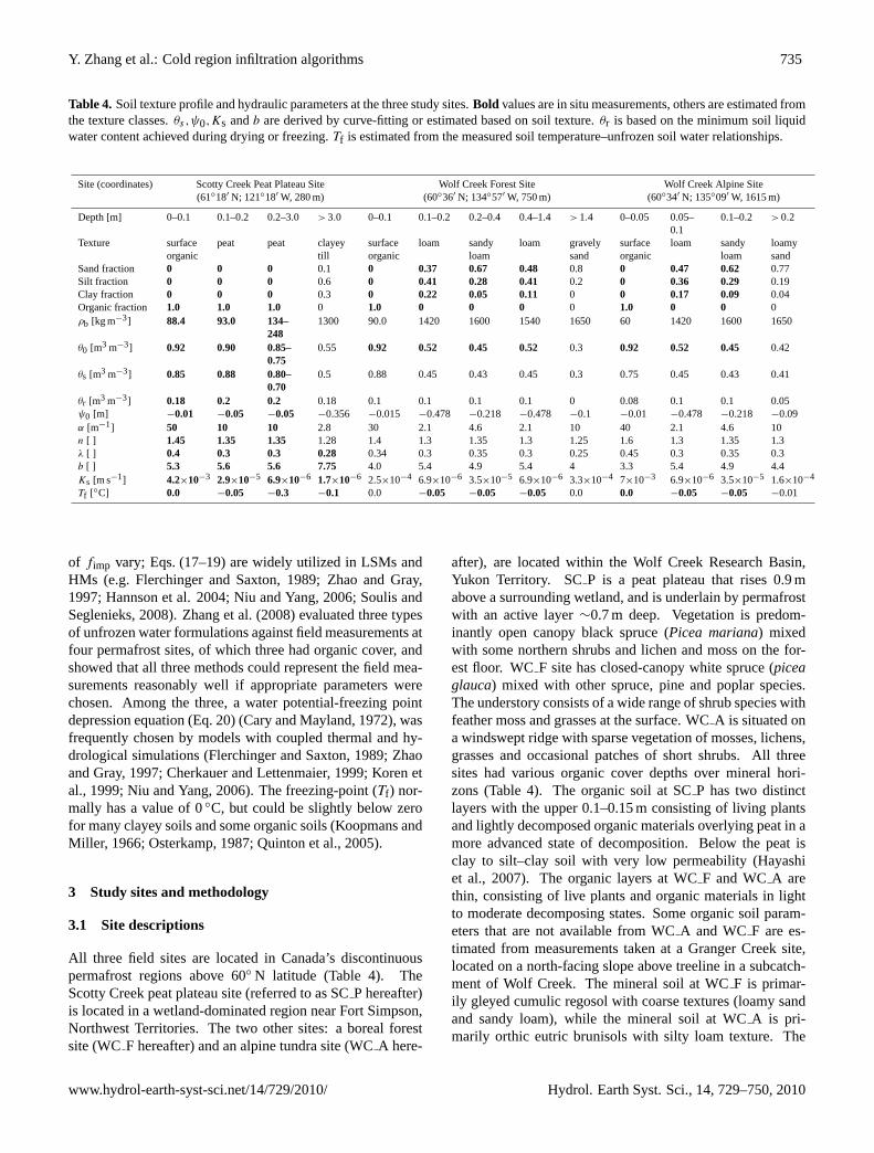
Table 4. Soil texture profile and hydraulic parameters at the three study sites.Bold values are in situ measurements, others are estimated fromthe texture classes.θs ,ψ0,Ks andb are derived by curve-fitting or estimated based on soil texture.θr is based on the minimum soil liquidwater content achieved during drying or freezing.Tf is estimated from the measured soil temperature–unfrozen soil water relationships.
Site (coordinates) Scotty Creek Peat Plateau Site Wolf Creek Forest Site Wolf Creek Alpine Site(61◦18′ N; 121◦18′ W, 280 m) (60◦36′ N; 134◦57′ W, 750 m) (60◦34′ N; 135◦09′ W, 1615 m)
Depth [m] 0–0.1 0.1–0.2 0.2–3.0 >3.0 0–0.1 0.1–0.2 0.2–0.4 0.4–1.4 >1.4 0–0.05 0.05–0.1
0.1–0.2 >0.2
Texture surfaceorganic
peat peat clayeytill
surfaceorganic
loam sandyloam
loam gravelysand
surfaceorganic
loam sandyloam
loamysand
Sand fraction 0 0 0 0.1 0 0.37 0.67 0.48 0.8 0 0.47 0.62 0.77Silt fraction 0 0 0 0.6 0 0.41 0.28 0.41 0.2 0 0.36 0.29 0.19Clay fraction 0 0 0 0.3 0 0.22 0.05 0.11 0 0 0.17 0.09 0.04Organic fraction 1.0 1.0 1.0 0 1.0 0 0 0 0 1.0 0 0 0ρb [kg m−3] 88.4 93.0 134–
2481300 90.0 1420 1600 1540 1650 60 1420 1600 1650
θ0 [m3 m−3] 0.92 0.90 0.85–0.75
0.55 0.92 0.52 0.45 0.52 0.3 0.92 0.52 0.45 0.42
θs [m3 m−3] 0.85 0.88 0.80–0.70
0.5 0.88 0.45 0.43 0.45 0.3 0.75 0.45 0.43 0.41
θr [m3 m−3] 0.18 0.2 0.2 0.18 0.1 0.1 0.1 0.1 0 0.08 0.1 0.1 0.05ψ0 [m] −0.01 −0.05 −0.05 −0.356 −0.015 −0.478 −0.218 −0.478 −0.1 −0.01 −0.478 −0.218 −0.09α [m−1] 50 10 10 2.8 30 2.1 4.6 2.1 10 40 2.1 4.6 10n [ ] 1.45 1.35 1.35 1.28 1.4 1.3 1.35 1.3 1.25 1.6 1.3 1.35 1.3λ [ ] 0.4 0.3 0.3 0.28 0.34 0.3 0.35 0.3 0.25 0.45 0.3 0.35 0.3b [ ] 5.3 5.6 5.6 7.75 4.0 5.4 4.9 5.4 4 3.3 5.4 4.9 4.4Ks [m s−1] 4.2×10⁻³ 2.9×10⁻⁵ 6.9×10⁻⁶ 1.7×10⁻⁶ 2.5×10⁻⁴ 6.9×10⁻⁶ 3.5×10⁻⁵ 6.9×10⁻⁶ 3.3×10⁻⁴ 7×10⁻³ 6.9×10⁻⁶ 3.5×10⁻⁵ 1.6×10⁻⁴
Tf [◦C] 0.0 −0.05 −0.3 −0.1 0.0 −0.05 −0.05 −0.05 0.0 0.0 −0.05 −0.05 −0.01
of fimp vary; Eqs. (17–19) are widely utilized in LSMs andHMs (e.g. Flerchinger and Saxton, 1989; Zhao and Gray,1997; Hannson et al. 2004; Niu and Yang, 2006; Soulis andSeglenieks, 2008). Zhang et al. (2008) evaluated three typesof unfrozen water formulations against field measurements atfour permafrost sites, of which three had organic cover, andshowed that all three methods could represent the field mea-surements reasonably well if appropriate parameters werechosen. Among the three, a water potential-freezing pointdepression equation (Eq. 20) (Cary and Mayland, 1972), wasfrequently chosen by models with coupled thermal and hy-drological simulations (Flerchinger and Saxton, 1989; Zhaoand Gray, 1997; Cherkauer and Lettenmaier, 1999; Koren etal., 1999; Niu and Yang, 2006). The freezing-point (Tf) nor-mally has a value of 0◦C, but could be slightly below zerofor many clayey soils and some organic soils (Koopmans andMiller, 1966; Osterkamp, 1987; Quinton et al., 2005).
3 Study sites and methodology
3.1 Site descriptions
All three field sites are located in Canada’s discontinuouspermafrost regions above 60◦ N latitude (Table 4). TheScotty Creek peat plateau site (referred to as SCP hereafter)is located in a wetland-dominated region near Fort Simpson,Northwest Territories. The two other sites: a boreal forestsite (WCF hereafter) and an alpine tundra site (WCA here-
after), are located within the Wolf Creek Research Basin,Yukon Territory. SCP is a peat plateau that rises 0.9 mabove a surrounding wetland, and is underlain by permafrostwith an active layer∼0.7 m deep. Vegetation is predom-inantly open canopy black spruce (Picea mariana) mixedwith some northern shrubs and lichen and moss on the for-est floor. WCF site has closed-canopy white spruce (piceaglauca) mixed with other spruce, pine and poplar species.The understory consists of a wide range of shrub species withfeather moss and grasses at the surface. WCA is situated ona windswept ridge with sparse vegetation of mosses, lichens,grasses and occasional patches of short shrubs. All threesites had various organic cover depths over mineral hori-zons (Table 4). The organic soil at SCP has two distinctlayers with the upper 0.1–0.15 m consisting of living plantsand lightly decomposed organic materials overlying peat in amore advanced state of decomposition. Below the peat isclay to silt–clay soil with very low permeability (Hayashiet al., 2007). The organic layers at WCF and WCA arethin, consisting of live plants and organic materials in lightto moderate decomposing states. Some organic soil param-eters that are not available from WCA and WCF are es-timated from measurements taken at a Granger Creek site,located on a north-facing slope above treeline in a subcatch-ment of Wolf Creek. The mineral soil at WCF is primar-ily gleyed cumulic regosol with coarse textures (loamy sandand sandy loam), while the mineral soil at WCA is pri-marily orthic eutric brunisols with silty loam texture. The
www.hydrol-earth-syst-sci.net/14/729/2010/ Hydrol. Earth Syst. Sci., 14, 729–750, 2010
736 Y. Zhang et al.: Cold region infiltration algorithms
climate of Scotty Creek and Wolf Creek is characterized assub-arctic dry continental climate, with short, dry summers,and long cold winters. Based on 1971–2000 averages (Envi-ronment Canada, 2009), mean annual air temperature at FortSimpson airport (50 km north of Scotty Creek) is−3.2◦C,and the mean January and July temperatures are−25.4◦Cand 17.2◦C, respectively. Average annual precipitation is369 mm, of which 39% falls as snow. Mean annual air tem-perature at Whitehorse airport (15 km north of Wolf Creek)is −0.7◦C, with mean January and July temperatures are−17.7◦C and 14.1◦C, respectively. Average annual precip-itation is 267.4 mm, of which 39% falls as snow. Springsnowmelt accounts for considerable amount of water inputsat both watersheds (Carey and Woo, 2001; Wright et al.,2008).
3.2 Field measurements and water balance components
Field measurement periods extending from late March orearly April to end of August were chosen to conduct modeltests at all three sites. Infiltration scenarios include snowmeltinfiltration into frozen or thawing ground, and rainfall infil-tration into the thawed active layer. Two seasons from eachsite, i.e. 2004 and 2005 for SCP, and 1998 and 1999 forWC F and WCA, were selected based on the availabilityof field data. Data from 1998 and 2004 were used for cali-bration of unknown parameters and initial conditions, whiledata from 1999 and 2005 were used for model validation.Details of field measurements and the methods to quantifythe water balance components can be found in Hayashi etal. (2007) and Wright et al. (2008) for Scotty Creek site,and in Pomeroy and Granger (1999) and Janowicz (2000) forWolf Creek sites.
3.2.1 Snowmelt (Msn)
Daily Msn was calculated from the difference in successivedaily values of snow water equivalent (SWE). This approachassumes that sublimation and evaporation from the meltingsnow are negligible. SWE at SCP was directly measured at5 m intervals along a 41 m transect, while SWE at WCF andWC A were determined by daily snow depth measurementsvia ultrasonic depth sensors (Campbell UDG01) and snowdensity sampled at variable times at 25 m intervals along a625 m transect. Average SWE values along the transectswere used in this study.
3.2.2 Soil temperature (T ) and thaw depth (ZT)
Soil temperatures at various depths were continuouslyrecorded at all three sites. The depths are 0.05 m, 0.1 m,0.15 m, 0.2 m, 0.25 m, 0.3 m, 0.4 m, 0.5 m, 0.6 m and 0.7 m atSC P, 0.05 m, 0.15 m, 0.3 m and 0.8 m at WCF, and 0.05 mand 0.15 m at WCA. ZT was derived from the temperaturemeasurements after Zhang et al. (2008). Ground surface tem-perature (Ts) at SCP was directly measured by thermistor
under snow cover and by infrared sensor once snowfree.Tsat WC F and WCA is estimated from air temperature duringsnowfree period and from temperatures measured at 0.1 mabove and 0.05 m below the ground surface during snow-cover period.
3.2.3 Evapotranspiration (ET)
Wright et al. (2008) calibrated the coefficientC6 in Priestley-Taylor ET Eq. (21) for three different land-cover types atSC P site with lysimeter measured ET data. The averageC6 value for the peat plateau ground surface ranged from0.68–0.91. Here, a value of 0.82 gave the best soil mois-ture simulations during the calibration period (2004), thusadopted for model testing period (2005). At Wolf Creek(WC F and WCP), an ET estimation method (Eq. 22), de-veloped by Granger and Gray (1989), was implemented byGranger (1999), and thus adopted in this study.
3.2.4 Soil water content
Daily liquid soil water contents (θl) were measured at allthree sites using site-calibrated TDR or water content reflec-tometer (CS-615) probes throughout the study period. Themeasurement depths are 0.1 m, 0.2 m, 0.3 m, and 0.4 m atSC P; 0.05 m, 0.15 m, 0.3 m and 0.8 m at WCF; and 0.05 mand 0.15 m at WCA. At WC F and WCA, changes of to-tal soil water content (ice + liquid water,θT) were monitoredduring snowmelt seasons using twin-probe gamma attenua-tion techniques as described by Gray and Granger (1986).The maximum monitoring depths were 1.2 m at WCF and0.8 m at WCA. Absolute values ofθT were estimated fromthe changes with respect to a reference measurement the pre-vious fall or subsequent summer when the active layer isthawed. θT was not regularly measured at SCP site, how-ever, values forθT prior to snow melt were estimated fromtwo θT profile measurements, one by TDR in the fall of 2002immediately before the freeze-up and another by two 0.7 mdeep frozen peat cores sampled near the study pit on 6 April2003 (Hayashi et al., 2007), using the procedure described inWright et al. (2008).
3.2.5 Infiltration and runoff
The cumulative infiltration (CINFi) of snowmelt (Msn)
and/or rainfall (R) is estimated from other measured waterbalance components as listed in Eqs. (23–24). Equation (23)is used for SCP and Eq. (24) is used for WCF and WCA.Equation (23) assumes that the freezing of infiltrated liquidwater during the melt period is negligible, thus the meltedsoil water (Msw) could be estimated from changingZT be-tween two time steps. Runoff (CROF) is estimated by thedifference between water input (R+Msn) and infiltration(Eq. 25).
Hydrol. Earth Syst. Sci., 14, 729–750, 2010 www.hydrol-earth-syst-sci.net/14/729/2010/
Y. Zhang et al.: Cold region infiltration algorithms 737
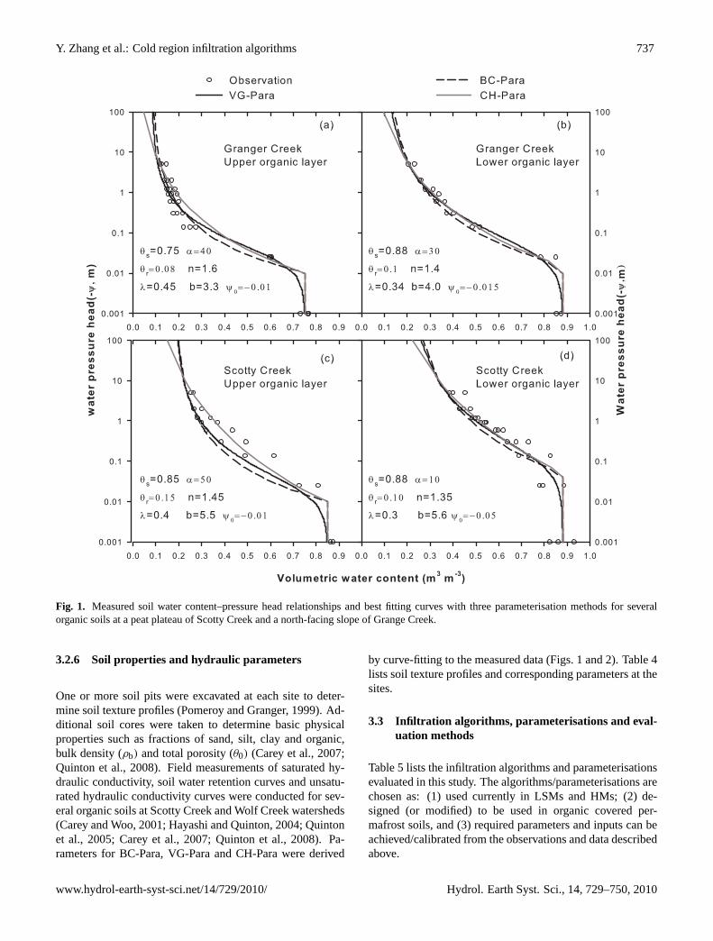
Fig. 1. Measured soil water content–pressure head relationships and best fitting curves with three parameterisation methods for severalorganic soils at a peat plateau of Scotty Creek and a north-facing slope of Grange Creek.
3.2.6 Soil properties and hydraulic parameters
One or more soil pits were excavated at each site to deter-mine soil texture profiles (Pomeroy and Granger, 1999). Ad-ditional soil cores were taken to determine basic physicalproperties such as fractions of sand, silt, clay and organic,bulk density (ρb) and total porosity (θ0) (Carey et al., 2007;Quinton et al., 2008). Field measurements of saturated hy-draulic conductivity, soil water retention curves and unsatu-rated hydraulic conductivity curves were conducted for sev-eral organic soils at Scotty Creek and Wolf Creek watersheds(Carey and Woo, 2001; Hayashi and Quinton, 2004; Quintonet al., 2005; Carey et al., 2007; Quinton et al., 2008). Pa-rameters for BC-Para, VG-Para and CH-Para were derived
by curve-fitting to the measured data (Figs. 1 and 2). Table 4lists soil texture profiles and corresponding parameters at thesites.
3.3 Infiltration algorithms, parameterisations and eval-uation methods
Table 5 lists the infiltration algorithms and parameterisationsevaluated in this study. The algorithms/parameterisations arechosen as: (1) used currently in LSMs and HMs; (2) de-signed (or modified) to be used in organic covered per-mafrost soils, and (3) required parameters and inputs can beachieved/calibrated from the observations and data describedabove.
www.hydrol-earth-syst-sci.net/14/729/2010/ Hydrol. Earth Syst. Sci., 14, 729–750, 2010
738 Y. Zhang et al.: Cold region infiltration algorithms
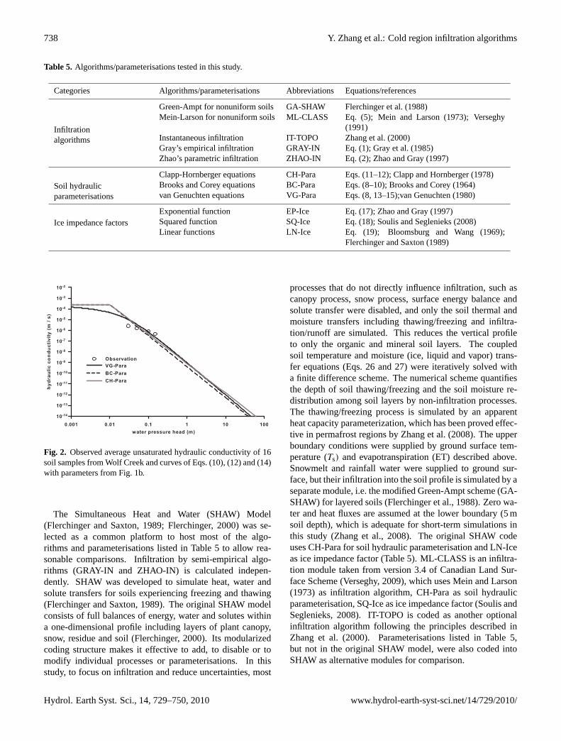
Table 5. Algorithms/parameterisations tested in this study.
Categories Algorithms/parameterisations Abbreviations Equations/references
Infiltration
Green-Ampt for nonuniform soils GA-SHAW Flerchinger et al. (1988)
algorithms
Mein-Larson for nonuniform soils ML-CLASS Eq. (5); Mein and Larson (1973); Verseghy(1991)
Instantaneous infiltration IT-TOPO Zhang et al. (2000)Gray’s empirical infiltration GRAY-IN Eq. (1); Gray et al. (1985)Zhao’s parametric infiltration ZHAO-IN Eq. (2); Zhao and Gray (1997)
Soil hydraulicClapp-Hornberger equations CH-Para Eqs. (11–12); Clapp and Hornberger (1978)
parameterisationsBrooks and Corey equations BC-Para Eqs. (8–10); Brooks and Corey (1964)van Genuchten equations VG-Para Eqs. (8, 13–15);van Genuchten (1980)
Ice impedance factorsExponential function EP-Ice Eq. (17); Zhao and Gray (1997)Squared function SQ-Ice Eq. (18); Soulis and Seglenieks (2008)Linear functions LN-Ice Eq. (19); Bloomsburg and Wang (1969);
Flerchinger and Saxton (1989)
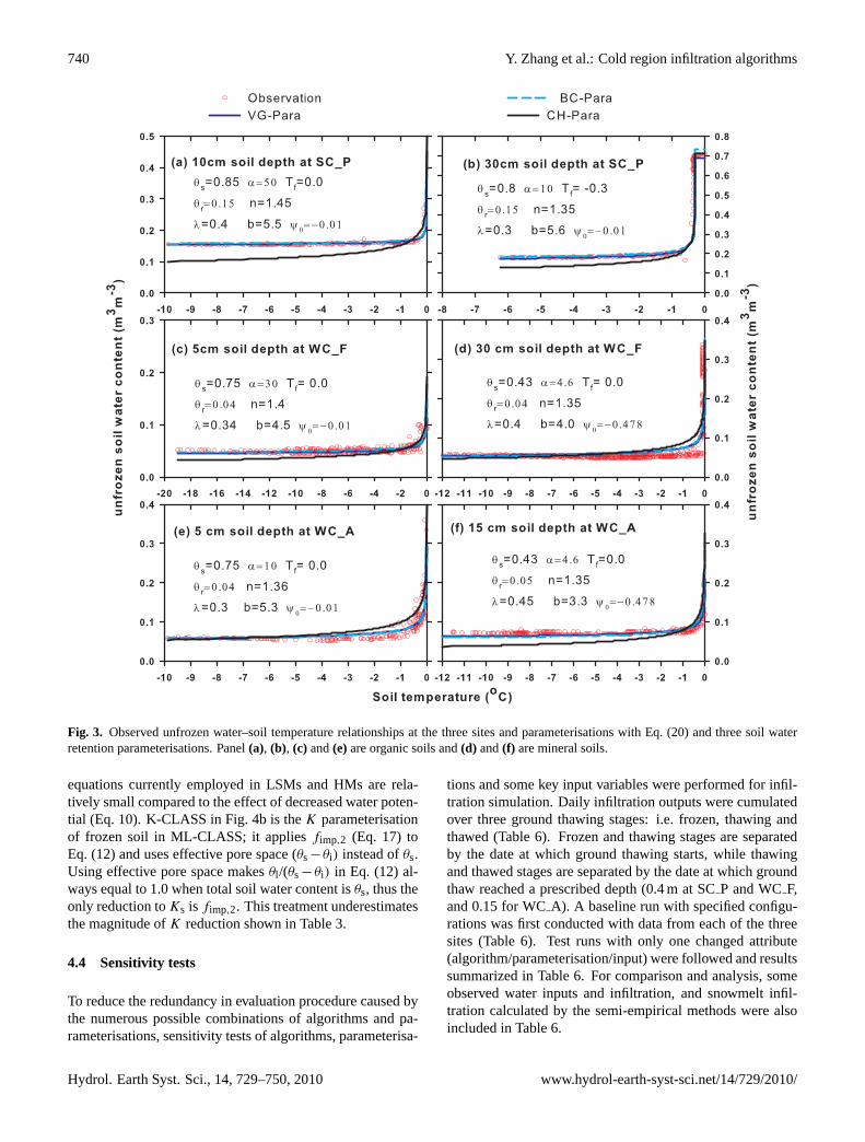
Fig. 2. Observed average unsaturated hydraulic conductivity of 16soil samples from Wolf Creek and curves of Eqs. (10), (12) and (14)with parameters from Fig. 1b.
The Simultaneous Heat and Water (SHAW) Model(Flerchinger and Saxton, 1989; Flerchinger, 2000) was se-lected as a common platform to host most of the algo-rithms and parameterisations listed in Table 5 to allow rea-sonable comparisons. Infiltration by semi-empirical algo-rithms (GRAY-IN and ZHAO-IN) is calculated indepen-dently. SHAW was developed to simulate heat, water andsolute transfers for soils experiencing freezing and thawing(Flerchinger and Saxton, 1989). The original SHAW modelconsists of full balances of energy, water and solutes withina one-dimensional profile including layers of plant canopy,snow, residue and soil (Flerchinger, 2000). Its modularizedcoding structure makes it effective to add, to disable or tomodify individual processes or parameterisations. In thisstudy, to focus on infiltration and reduce uncertainties, most
processes that do not directly influence infiltration, such ascanopy process, snow process, surface energy balance andsolute transfer were disabled, and only the soil thermal andmoisture transfers including thawing/freezing and infiltra-tion/runoff are simulated. This reduces the vertical profileto only the organic and mineral soil layers. The coupledsoil temperature and moisture (ice, liquid and vapor) trans-fer equations (Eqs. 26 and 27) were iteratively solved witha finite difference scheme. The numerical scheme quantifiesthe depth of soil thawing/freezing and the soil moisture re-distribution among soil layers by non-infiltration processes.The thawing/freezing process is simulated by an apparentheat capacity parameterization, which has been proved effec-tive in permafrost regions by Zhang et al. (2008). The upperboundary conditions were supplied by ground surface tem-perature (Ts) and evapotranspiration (ET) described above.Snowmelt and rainfall water were supplied to ground sur-face, but their infiltration into the soil profile is simulated by aseparate module, i.e. the modified Green-Ampt scheme (GA-SHAW) for layered soils (Flerchinger et al., 1988). Zero wa-ter and heat fluxes are assumed at the lower boundary (5 msoil depth), which is adequate for short-term simulations inthis study (Zhang et al., 2008). The original SHAW codeuses CH-Para for soil hydraulic parameterisation and LN-Iceas ice impedance factor (Table 5). ML-CLASS is an infiltra-tion module taken from version 3.4 of Canadian Land Sur-face Scheme (Verseghy, 2009), which uses Mein and Larson(1973) as infiltration algorithm, CH-Para as soil hydraulicparameterisation, SQ-Ice as ice impedance factor (Soulis andSeglenieks, 2008). IT-TOPO is coded as another optionalinfiltration algorithm following the principles described inZhang et al. (2000). Parameterisations listed in Table 5,but not in the original SHAW model, were also coded intoSHAW as alternative modules for comparison.
Hydrol. Earth Syst. Sci., 14, 729–750, 2010 www.hydrol-earth-syst-sci.net/14/729/2010/

Y. Zhang et al.: Cold region infiltration algorithms 739
The modified SHAW model is fed with daily surface forc-ing variables includingTs, R, Msn and ET. Much smallerand dynamic time step (half-hourly or smaller) is used in-ternally to ensure convergence of the numerical scheme. A16-layer soil vertical resolution is used at all three sites. Thelayer depths are 0.05 m for top two layers, 0.1 m for 0.1–0.8 m depth and progressively increasing for deeper layersuntil the simulated soil bottom at 5 m. Site specific parame-ters (e.g. coefficients to quantifyTs and ET from known me-teorological variables) and unknown initial conditions (e.g.initial soil temperatures and moisture profiles below the ob-servation depth) were achieved by fitting the simulated di-agnostic variables to their observed values during calibrationyears (1998 and 2004). The principal diagnostic variablesare thawing depth, cumulative infiltration/runoff and soil liq-uid water content corresponding to the measurement depths.Since multiple unknowns and multiple diagnostic variablesare involved, an iterative procedure is performed until all thediagnostic variables achieve their best fitting results. Sim-ilar procedure has been performed in evaluating the thaw-ing/freezing simulations in Zhang et al. (2008). The cali-brated parameters and conditions at the end of calibrationperiods are then used to quantify the required inputs and ini-tiation conditions during the model validations years (1999and 2005). A common set of inputs and initial conditions areused for all the model validation runs with different infiltra-tion algorithms to ensure valid comparison of the algorithms.
4 Results and discussions
4.1 Soil hydraulic parameterisations
The most important soil hydraulic parameterisations for in-filtration/redistribution are the water retention curve (waterpotential vs. water content) and hydraulic conductivity curve(hydraulic conductivity vs. water potential or content). Allthree commonly used methods in Table 5 are able to fit ob-served soil water retention curves in moderate soil moistureranges for several organic soils (Fig. 1). Upon approach-ing saturation, both CH-Para and BC-Para calculate valuesaboveθs, which have to be capped byθs. When liquid wa-ter declines under frozen conditions with very low water po-tential, CH-Para gives liquid water content values belowθr.To counter this, many LSMs and HMs assume a minimumvalue for liquid water content (e.g. CLASS, Verseghy, 1991;SHAW, Flerchinger and Saxton, 1989). The discontinuity ofCH-Para and BC-Para for saturated or extremely dry (frozen)conditions may result in numerical convergence problems forthe moisture transfer equations (e.g. Eq. 27). Alternativetreatments such as the water balance method, or explicit so-lutions must be used when soil moisture approachesθs or θr(Flerchinger, 2000). Theoretically, VG-Para is more suitablefor numerical water transfer models due to its smoothnessover the entire soil moisture range. However, its current ap-
plication in operational LSMs and HMs is limited due to poorparameter availability of many soil types. Figure 2 shows un-saturated hydraulic conductivityK values observed by Careyet al. (2007) and simulated by the three parameterisationmethods using an estimatedKs value of 2.5×10⁻⁴ m s−1 andparameters in Fig. 1b. All three methods gave similarK val-ues in normal pressure head ranges, except under saturatedconditions when pressure head reaches zero. In this case,K
values calculated by CH-Para and BC-Para have to be cappedby Ks. Although only in a small pressure head range, ob-servedK values generally match calculated values.
4.2 Parameterisation of unfrozen water content
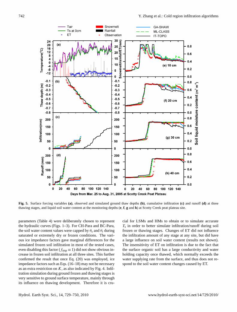
In this study, unfrozen water content is calculated by a waterpotential-freezing point depression equation (Eq. 20), com-bined with the reversed form of one of the three water reten-tion equations (Eq. 9, or 11, or 13). Values forψ0 are takenfrom Letts et al. (2000) for organic soils and from Clapp andHornberger (1978) for mineral soils, based on correspond-ing texture class. Similar to the performance in water re-tention simulations (Fig. 1), the discrepancies in simulatedunfrozen water curves by the three water retention equationswere mostly found when liquid water content reaches max-imum or minimum values due to soil temperature changes(Fig. 3). Those errors could be easily corrected by bound-ing the calculated unfrozen water content with observedθrand θs. Although from two different data sets, parametersobtained in Figs. 1 and 3 are similar for the same soil. Forexample, the parameters in Fig. 1c worked equally well inFig. 3a. Since unfrozen water and soil temperature are eas-ier to measure in permafrost soil than the soil water potential,these datasets can be an effective alternative to derive soil hy-draulic parameters from traditional pressure head measure-ments, as demonstrated by Spaans and Baker (1996) andFlerchinger et al. (2006). Most of the soil hydraulic parame-ters in Table 4 are derived by this method.
4.3 Reduction of hydraulic conductivity (K) due to soilfreezing
During soil freezing, two effects act to reduceK. First, thereduction of liquid water content will lower the water poten-tialψ (Eq. 9, or 11, or 13), reducingK in a similar manner assoil drying (Eq. 10, or 12, or 14). Second, an impedance fac-tor due to the presence of ice is applied toK (e.g. Eq. 17, or18, or 19). Figure 4 illustrates the changes of ice impedancefactors (Fig. 4a) and hydraulic conductivity with increasingsoil ice fraction (Fig. 4b). Soil parameters used are the sameas in Fig. 3d andKs is set for a typical loam as outlined inClapp and Hornberger (1978). The drying effect alone re-ducesK to similar orders of magnitude as those reported forfrozen soils in Table 3 (Fig. 4b). Although further reductionby an impedance factor such as Eq. (17) with aC5 value ashigh as 10 is noticeable, restrictions imposed by impedance
www.hydrol-earth-syst-sci.net/14/729/2010/ Hydrol. Earth Syst. Sci., 14, 729–750, 2010
740 Y. Zhang et al.: Cold region infiltration algorithms
Fig. 3. Observed unfrozen water–soil temperature relationships at the three sites and parameterisations with Eq. (20) and three soil waterretention parameterisations. Panel(a), (b), (c) and(e)are organic soils and(d) and(f) are mineral soils.
equations currently employed in LSMs and HMs are rela-tively small compared to the effect of decreased water poten-tial (Eq. 10). K-CLASS in Fig. 4b is theK parameterisationof frozen soil in ML-CLASS; it appliesfimp,2 (Eq. 17) toEq. (12) and uses effective pore space (θs−θi) instead ofθs.Using effective pore space makesθl /(θs−θi) in Eq. (12) al-ways equal to 1.0 when total soil water content isθs, thus theonly reduction toKs is fimp,2. This treatment underestimatesthe magnitude ofK reduction shown in Table 3.
4.4 Sensitivity tests
To reduce the redundancy in evaluation procedure caused bythe numerous possible combinations of algorithms and pa-rameterisations, sensitivity tests of algorithms, parameterisa-
tions and some key input variables were performed for infil-tration simulation. Daily infiltration outputs were cumulatedover three ground thawing stages: i.e. frozen, thawing andthawed (Table 6). Frozen and thawing stages are separatedby the date at which ground thawing starts, while thawingand thawed stages are separated by the date at which groundthaw reached a prescribed depth (0.4 m at SCP and WCF,and 0.15 for WCA). A baseline run with specified configu-rations was first conducted with data from each of the threesites (Table 6). Test runs with only one changed attribute(algorithm/parameterisation/input) were followed and resultssummarized in Table 6. For comparison and analysis, someobserved water inputs and infiltration, and snowmelt infil-tration calculated by the semi-empirical methods were alsoincluded in Table 6.
Hydrol. Earth Syst. Sci., 14, 729–750, 2010 www.hydrol-earth-syst-sci.net/14/729/2010/

Y. Zhang et al.: Cold region infiltration algorithms 741
Fig. 4. Parameterisations of ice impedance factor(a) and their reductions to hydraulic conductivity when applied to Eq. (10). The soilhydraulic parameters used are as in Fig. 3d.
Table 6. Observed and simulated infiltration (mm) by different algorithms, parameterisations and boundary inputs for three ground thawingstages at the three permafrost sites.
Site Scotty Creek Peat Plateau Site Wolf Creek Forest Site Wolf Creek Alpine Site
Stagea Frozen Thawing Thawed Frozen Thawing Thawed Frozen Thawing ThawedSnowmelt + Rain 203.1 125.0 170.0 4.5 59.8 83.5 78.5 77.3 34.9Observation 24.0 80.0 – – 33.8d – 19.1 – –GRAY-INb 16.8 – 38.8 – 49.6 –ZHAO-IN 44.8 – – 10.1 41.0 – 29.7 7.7 –Baseline Runc 14.1 84.0 170.0 4.5 59.8 83.5 30.5 68.7 34.9ML-CLASS 23.0 78.0 170.0 4.5 59.8 83.5 67.9 77.3 34.9IT-TOPO 11.2 69.6 170.0 0 18.2 83.5 0 4.7 34.9BC-Para 14.9 89.3 170.0 4.5 59.8 83.5 30.5 67.5 34.9VG-Para 14.6 88.2 170.0 4.5 59.8 83.5 20.8 68.7 34.9SQ-Ice 12.8 85.0 170.0 4.5 59.8 83.5 30.4 67.5 34.9EP-Ice (C5=2) 12.9 84.9 170.0 4.5 59.8 83.5 30.4 68.4 34.9EP-Ice (C5=10) 3.3 94.8 170.0 4.5 59.8 83.5 30.4 60.2 34.9fimp ≡ 1 17.5 80.6 170.0 4.5 59.8 83.5 30.5 67.5 34.9Ts+1◦C 24.4 73.1 170.0 4.5 59.8 83.5 51.5 74.4 34.9Ts–1◦C 9.2 89.7 170.0 2.7 51.0 83.5 1.5 67.5 34.9ET increase 20% 14.1 84.0 170.0 4.5 59.8 83.5 30.5 68.7 34.9ET decrease 20% 14.1 84.0 170.0 4.5 59.8 83.5 30.5 68.7 34.9
a Frozen, thawing and thawed stages are 26 March–26 April, 27 April–6 June and 7 June–31 August 2005 for SCP, 1 April–15 April, 16April–24 May and 25 May–31 August 1999 for WCF, and 1 April–12 May, 13 May–4 June, and 5 June–31 August 1999 for WCA.b This method gives the total snowmelt infiltration, which include all infiltration during ground frozen and some during thawing.c Baseline run is defined as using SHAW infiltration algorithm, LN-Para for soil water retention and hydraulic conductivity, SQ-Ice for iceimpedance factor with standard inputs from observation/estimation.d This value only accounted for infiltration from 16 April to 27 April 1999.
The sensitivity of the simulated infiltration to the changesof algorithms, parameterisations or inputs only occurred dur-ing soil frozen and thawing stages at all sites (Table 6). Oncethe ground thawed to a certain depth, all water infiltrated
into the soil regardless the configured algorithms, parame-terisations or inputs. The three soil hydraulic parameterisa-tions (CH-Para, BC-Para and VG-Para) had little influenceon the simulations during all three stages. In this study,
www.hydrol-earth-syst-sci.net/14/729/2010/ Hydrol. Earth Syst. Sci., 14, 729–750, 2010
742 Y. Zhang et al.: Cold region infiltration algorithms
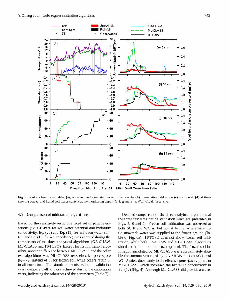
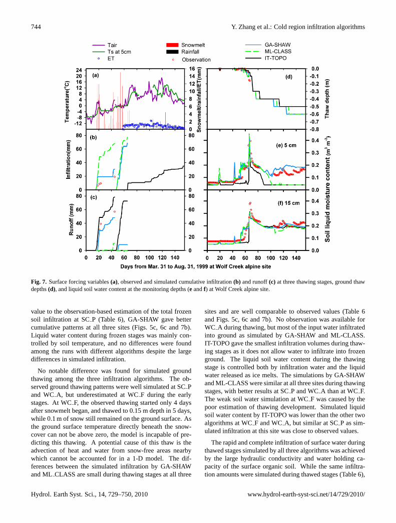
Fig. 5. Surface forcing variables(a), observed and simulated ground thaw depths(b), cumulative infiltration(c) and runoff(d) at threethawing stages, and liquid soil water content at the monitoring depths (e, f, g andh) at Scotty Creek peat plateau site.
parameters (Table 4) were deliberately chosen to representthe hydraulic curves (Figs. 1–3). For CH-Para and BC-Para,the soil water content values were capped byθs andθr duringsaturated or extremely dry or frozen conditions. The vari-ous ice impedance factors gave marginal differences for thesimulated frozen soil infiltration in most of the tested cases,even disabling this factor (fimp ≡ 1) did not show obvious in-crease in frozen soil infiltration at all three sites. This furtherconfirmed the result that once Eq. (20) was employed, iceimpedance factors such as Eqs. (16–18) may not be necessaryas an extra restriction onK, as also indicated by Fig. 4. Infil-tration simulation during ground frozen and thawing stages isvery sensitive to ground surface temperature, mainly throughits influence on thawing development. Therefore it is cru-
cial for LSMs and HMs to obtain or to simulate accurateTs in order to better simulate infiltration/runoff during soilfrozen or thawing stages. Changes of ET did not influencethe infiltration amount of any stage at any site, but did havea large influence on soil water content (results not shown).The insensitivity of ET on infiltration is due to the fact thatthe surface organic soil has a large conductivity and waterholding capacity once thawed, which normally exceeds thewater supplying rate from the surface, and thus does not re-spond to the soil water content changes caused by ET.
Hydrol. Earth Syst. Sci., 14, 729–750, 2010 www.hydrol-earth-syst-sci.net/14/729/2010/
Y. Zhang et al.: Cold region infiltration algorithms 743
Fig. 6. Surface forcing variables(a), observed and simulated ground thaw depths(b), cumulative infiltration(c) and runoff(d) at threethawing stages, and liquid soil water content at the monitoring depths (e, f, g andh) at Wolf Creek forest site.
4.5 Comparison of infiltration algorithms
Based on the sensitivity tests, one fixed set of parameteri-sations (i.e. CH-Para for soil water potential and hydraulicconductivity, Eq. (20) and Eq. (11) for unfrozen water con-tent and Eq. (18) for ice impedance), was adopted during thecomparison of the three analytical algorithms (GA-SHAW,ML-CLASS and IT-TOPO). Except for its infiltration algo-rithm, another difference between ML-CLASS and the othertwo algorithms was ML-CLASS uses effective pore space(θs− θi) instead ofθs for frozen soil while others retainθsin all conditions. The simulation statistics in the validationyears compare well to those achieved during the calibrationyears, indicating the robustness of the parameters (Table 7).
Detailed comparison of the three analytical algorithms atthe three test sites during validation years are presented inFigs. 5, 6 and 7. Frozen soil infiltration was observed atboth SCP and WCA, but not at WCF, where very lit-tle snowmelt water was supplied to the frozen ground (Ta-ble 6, Fig. 6a). IT-TOPO does not allow frozen soil infil-tration, while both GA-SHAW and ML-CLASS algorithmssimulated infiltration into frozen ground. The frozen soil in-filtration simulated by ML-CLASS was approximately dou-ble the amount simulated by GA-SHAW at both SCP andWC A sites, due mainly to the effective pore space applied inML-CLASS, which increased the hydraulic conductivity inEq. (12) (Fig. 4). Although ML-CLASS did provide a closer
www.hydrol-earth-syst-sci.net/14/729/2010/ Hydrol. Earth Syst. Sci., 14, 729–750, 2010
744 Y. Zhang et al.: Cold region infiltration algorithms
Fig. 7. Surface forcing variables(a), observed and simulated cumulative infiltration(b) and runoff(c) at three thawing stages, ground thawdepths(d), and liquid soil water content at the monitoring depths (eandf) at Wolf Creek alpine site.
value to the observation-based estimation of the total frozensoil infiltration at SCP (Table 6), GA-SHAW gave bettercumulative patterns at all three sites (Figs. 5c, 6c and 7b).Liquid water content during frozen stages was mainly con-trolled by soil temperature, and no differences were foundamong the runs with different algorithms despite the largedifferences in simulated infiltration.
No notable difference was found for simulated groundthawing among the three infiltration algorithms. The ob-served ground thawing patterns were well simulated at SCPand WCA, but underestimated at WCF during the earlystages. At WCF, the observed thawing started only 4 daysafter snowmelt began, and thawed to 0.15 m depth in 5 days,while 0.1 m of snow still remained on the ground surface. Asthe ground surface temperature directly beneath the snow-cover can not be above zero, the model is incapable of pre-dicting this thawing. A potential cause of this thaw is theadvection of heat and water from snow-free areas nearbywhich cannot be accounted for in a 1-D model. The dif-ferences between the simulated infiltration by GA-SHAWand ML CLASS are small during thawing stages at all three
sites and are well comparable to observed values (Table 6and Figs. 5c, 6c and 7b). No observation was available forWC A during thawing, but most of the input water infiltratedinto ground as simulated by GA-SHAW and ML-CLASS.IT-TOPO gave the smallest infiltration volumes during thaw-ing stages as it does not allow water to infiltrate into frozenground. The liquid soil water content during the thawingstage is controlled both by infiltration water and the liquidwater released as ice melts. The simulations by GA-SHAWand ML-CLASS were similar at all three sites during thawingstages, with better results at SCP and WCA than at WCF.The weak soil water simulation at WCF was caused by thepoor estimation of thawing development. Simulated liquidsoil water content by IT-TOPO was lower than the other twoalgorithms at WCF and WCA, but similar at SCP as sim-ulated infiltration at this site was close to observed values.
The rapid and complete infiltration of surface water duringthawed stages simulated by all three algorithms was achievedby the large hydraulic conductivity and water holding ca-pacity of the surface organic soil. While the same infiltra-tion amounts were simulated during thawed stages (Table 6),
Hydrol. Earth Syst. Sci., 14, 729–750, 2010 www.hydrol-earth-syst-sci.net/14/729/2010/
Y. Zhang et al.: Cold region infiltration algorithms 745
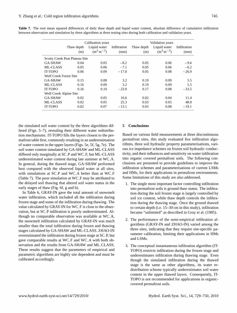
Table 7. The root mean squared differences of daily thaw depth and liquid water content, absolute difference of cumulative infiltrationbetween observation and simulation by three algorithms at three testing sites during both calibration and validation years.
Calibration years Validation yearsThaw depth Liquid water Infiltration Thaw depth Liquid water Infiltration
(m) (m3 m−3) (mm) (m) (m3 m−3) (mm)
Scotty Creek Peat Plateau SiteGA-SHAW 0.04 0.05 −8.2 0.05 0.06 −9.6ML-CLASS 0.05 0.06 −7.1 0.05 0.06 −6.2IT-TOPO 0.06 0.09 −17.0 0.05 0.08 −26.9Wolf Creek Forest SiteGA-SHAW 0.15 0.08 3.2 0.19 0.09 5.5ML-CLASS 0.16 0.09 3.2 0.19 0.09 5.5IT-TOPO 0.16 0.10 −23.0 0.17 0.08 −33.5Wolf Creek Alpine SiteGA-SHAW 0.02 0.05 10.6 0.02 0.04 11.4ML-CLASS 0.02 0.05 25.3 0.03 0.05 48.8IT-TOPO 0.02 0.07 −13.1 0.03 0.08 −19.1
the simulated soil water content by the three algorithms dif-fered (Figs. 5–7), revealing their different water redistribu-tion mechanisms. IT-TOPO fills the layers closest to the per-mafrost table first, commonly resulting in an underestimationof water content in the upper layers (Figs. 5e, 5f, 5g, 7e). Thesoil water content simulated by GA-SHAW and ML-CLASSdiffered only marginally at SCP and WCF, but ML-CLASSunderestimated water content during late summer at WCA.In general, during the thawed stage, GA-SHAW performedbest compared with the observed liquid water at all sites,with simulations at SCP and WCA better than at WCF(Table 7). The poor simulation at WCF may be attributed tothe delayed soil thawing that altered soil water status in theearly stages of thaw (Fig. 6f, g and h).
In Table 6, GRAY-IN gave the total amount of snowmeltwater infiltration, which included all the infiltration duringfrozen stage and some of the infiltration during thawing. Thevalue calculated by GRAY-IN for WCF is close to the obser-vation, but at SCP infiltration is poorly underestimated. Al-though no comparable observation was available at WCA,the snowmelt infiltration calculated by GRAY-IN was muchsmaller than the total infiltration during frozen and thawingstages calculated by GA-SHAW and ML-CLASS. ZHAO-INoverestimated the infiltration during frozen stage at SCP, butgave comparable results at WCF and WCA with both ob-servation and the results from GA-SHAW and MLCLASS.These results suggest that the parameters of empirical andparametric algorithms are highly site dependent and must becalibrated accordingly.
5 Conclusions
Based on various field measurements at three discontinuouspermafrost sites, this study evaluated five infiltration algo-rithms, three soil hydraulic property parameterisations, vari-ous ice impedance schemes on frozen soil hydraulic conduc-tivity, and their influences and sensitivity on water infiltrationinto organic covered permafrost soils. The following con-clusions are presented to provide guidelines to improve theinfiltration schemes and parameterisations of current LSMsand HMs, for their applications in permafrost environments.Some limitations of this study are also addressed.
1. The single most important factor controlling infiltrationinto permafrost soils is ground thaw status. The infiltra-tion during the soil frozen stage is largely controlled bysoil ice content, while thaw depth controls the infiltra-tion during the thawing stage. Once the ground thawedto certain depth (i.e. 15–30 cm in this study), infiltrationbecame “unlimited” as described in Gray et al. (1985).
2. The performance of the semi-empirical infiltration al-gorithms (GRAY-IN and ZHAO-IN) varied among thethree sites, indicating that they require site-specific pa-rameter calibration, limiting their applications in HMsand LSMs.
3. The conceptual instantaneous infiltration algorithm (IT-TOPO) restricts infiltration during the frozen stage andunderestimates infiltration during thawing stage. Eventhough the simulated infiltration during the thawedstage is the same as other algorithms, its water re-distribution scheme typically underestimates soil watercontent in the upper thawed layers. Consequently, IT-TOPO is not recommended for applications in organic-covered permafrost soils.
www.hydrol-earth-syst-sci.net/14/729/2010/ Hydrol. Earth Syst. Sci., 14, 729–750, 2010
746 Y. Zhang et al.: Cold region infiltration algorithms
4. The two analytical algorithms (GA-SHAW and ML-CLASS) gave similar infiltration simulations duringmost stages and site conditions. Some differences ex-hibited during the ground frozen and thawing stageswere caused by their different parameterisation offrozen soil hydraulic conductivity (K), rather than theinfiltration algorithms used: i.e. modified Green-Amptand Mein-Larson for layered soil. This study recom-mends both algorithms for infiltration simulation at or-ganic cover permafrost sites, but the parameterisation offrozen groundK in current CLASS frozen soil module(Verseghy, 2009), particularly the introduction of an ef-fective pore space (Soulis and Seglenieks, 2008), mayoverestimate the frozen soilK.
5. With properly chosen parameters, the three soil hy-draulic property parameterisations, i.e. Clapp and Horn-berger (CH-Para), Brooks and Corey (BC-Para), andvan Genuchten (VG-Para), achieve similar soil waterretention and hydraulic conductivity curves for normalsoil moisture ranges. However, the calculated soil liq-uid water content and hydraulic conductivity by CH-Para and BC-Para should be bounded by maximum andminimum values during saturation or frozen conditions.This treatment could cause convergence problems forinfiltration schemes coupled with numerical moistureredistribution schemes. While VG-Para gives smoothparameterisation curves for all soil moisture range, itsapplication is restricted by the general availability of pa-rameters. Paired measurement data of unfrozen watercontent (θl) and subfreezing soil temperature (Ts) couldbe used to derive soil hydraulic parameters by fittingθl −Ts relationships derived from Eq. (20) and the soilwater retention equations.
6. Only by applying Eq. (20) to unsaturated hydraulic con-ductivity (K) equations (Eq. 10, 12 or 14) could realis-tic simulation of the reduction ofK due to soil frozenbe achieved in the range of observations. Further reduc-tion by various ice impedance factors as employed inmany land surface and hydrological models may not benecessary in organic-covered permafrost soils.
7. Sensitivity tests indicate that simulated infiltration issensitive to algorithms, parameterisations and inputchanges only during the frozen and fast thawing stages.The infiltration at these stages is sensitive to ground sur-face temperature but not to evapotranspiration.
8. All three sites in this study are located in relative flatareas, reducing the potential for lateral flow. However,the abnormal ground thaw under snowcover at WCFsite (Fig. 6b) was most likely caused by the advectionof heat and/or water from snow-free patches. Slopesare common feature in permafrost terrain and cannot beomitted in operational LSMs or HMs for infiltration andrunoff simulations.
9. The preferential flow suggested by many permafrost in-filtration studies (e.g. Mackay, 1983) can be representedby high hydraulic conductivity values parameterised forsurface organic layers. No additional algorithm is nec-essary to account for preferential flow at these sites.
Appendix A
Notation
b empirical coefficient in Clapp-Hornberger equations, [ ]
Ci,i= 1,7 empirical coefficients, [ ]CINFi,i= 1,2 cumulative infiltration estimated from
field observation, [mm]CROF cumulative runoff estimated from
field observation, [mm]Cs volumetric heat capacity of soil,
[J m−3 C−1]Cl specific heat capacity of soil, [J kg−1
C−1]Ea relative drying power of air in
Granger equation, [mm d−1].ET evapotranspiration, [mm d−1]fimp,i i= 1,3 different expressions of impedance
factor, [ ]g gravitational acceleration, [9.8 m s−2]G relative ET coefficient in Granger
equation, [ ]I ′ incremented infiltration depth, [m]INFi,i= 1,6 different expressions of rate of infil-
tration, [mm s−1]Ks saturated hydraulic conductivity for
unfrozen soil, [m s−1]◦
K unsaturated hydraulic conductivity,[m s−1]
KT soil thermal conductivity, [W m−1
C−1]◦
Kbtm saturated hydraulic conductivity atbottom layer, [m s−1]
Ktop saturated hydraulic conductivity attop layer, [m s−1]
Kw hydraulic conductivity at wettingfront, [m s−1]◦
m,n empirical coefficients in vanGenuchten equations, [ ]
Lf latent heat of fusion, 3.34×10⁸
[J m−3]Lv latent heat of vaporization, 2.51×10⁹
[J m−3]Msn amount of melt snow, [mm]Msw amount of melt soil ice, [mm]
Hydrol. Earth Syst. Sci., 14, 729–750, 2010 www.hydrol-earth-syst-sci.net/14/729/2010/
Y. Zhang et al.: Cold region infiltration algorithms 747
Qn net radiation, [J m−2 d−1]Qg soil heat flux, [J m−2 d−1]ql,qv soil liquid and vapor fluxes respec-
tively, [m s−1]R rainfall, [mm]S0 surface saturation during infiltration,
higher thanSI , [m3 m−3]Se effective saturation, [m3 m−3]SI premelt pore saturation in top 0–
30 cm soil layer, [m3 m−3]SWE premelt total snow water equivalent,
[mm]t infiltration time, [second]tp ponding start time, [second]T soil temperature, [◦C]Ta air temperature, [◦C]TI premelt average soil temperature in
top 0–30 cm soil layer, [◦C]Tf freezing point temperature, [◦C]Ts ground surface temperature, [◦C]U Source/sink term for water flux,
[m3 m−3 s−1]Z soil depth, [m]Zf infiltration depth, [m]Zp ponding depth, [m]ZT ground thaw depth, [m]Ztrn transition depth of hydraulic conduc-
tivity, [m]α constant in van Genuchten equation
(13 and 14), [m−1]β a parameter approximated from soil
sorptivity, initial moisture and rainfallintensity, [m2 s−1]
γ psychrometric constant [Pa◦C−1]δ slope of the saturation vapour
pressure-temperature curve,[Pa◦C−1]
θ0 soil porosity, [m3 m−3]θi volumetric fraction of soil ice con-
tent, [m3 m−3]θini Initial soil moisture content,
[m3 m−3]θl unfrozen (liquid) water content,
[m3 m−3]θr residue soil water content, [m3 m−3]θs saturated soil water (ice+liquid) con-
tent, [m3 m−3]θT total soil water (ice+liquid) content,
[m3 m−3]λ empirical coefficient in Brooks-Corey
equations, [ ]ρi , ρl , ρv density of ice, liquid water and vapor
respectively, [kg m−3]ψ soil water potential, [m]
ψ0 soil water potential at saturation or airentry potential, [m]
ψw soil water potential at wetting front, [m]1SWL changes of soil liquid water content in
the soil column, [mm]1SWT changes of soil total water content in the
soil column, [mm]
Acknowledgements.This study was supported by the CanadianFoundation for Climate and Atmospheric Sciences (CFCAS) viathe project: Improved processes and parameterisation for predic-tions in cold regions (IP3), International Polar Year (IPY) and theNatural Sciences and Engineering Research Council of Canada(NSERC). Masaki Hayashi provided some thoughtful insights andcontributed to the original field data collection. Nicole Wright andMatt MacDonald provided some processed observation data. Thesource code and documentation of CLASS frozen soil infiltrationmodule were obtained from Diana Verseghy and Ric Soulis.
Edited by: J. Pomeroy
References
Beven, K. J. and Kirkby, M. J.: A physically based variable con-tributing area model of basin hydrology, Hydrol. Sci. Bull., 24,43–69, 1979.
Bloomsburg, G. L. and Wang, S. J.: Effect of moisture contenton permeability of frozen soils, 16th annual meeting of PacificNorthwest Region, American Geophysical Union, Portland, Ore-gon, 16–17 October 1969.
Boike, J., Roth, K., and Overduin, P.: Thermal and hydrologicdynamics of the active layer at a continuous permafrost site(Taymyr Peninsula, Siberia), Water Resour. Res., 34, 355–363,1998.
Bonan, G. B.: A biophysical surface energy budget analysis of soiltemperature in the boreal forests of interior Alaska, Water Re-sour. Res., 27, 767–781, 1991.
Bouwer, H.: Infiltration of water into non-uniform soil, J. Irrig.Drain. Div., 95 (IR4), 451, 1969.
Brooks, R. H. and Corey, A. J.: Hydraulic properties of porous me-dia. Hydrol. Paper 3, Colo. State Univ., Fort Collins, CO., 27 pp.,1964.
Burt, T. P. and Williams, P. J.: Hydraulic conductivity in frozensoils, Earth Surf. Process., 1, 349–360, 1976.
Carey, S. K. and Woo, M.-K.: Slope runoff processes and flow gen-eration in a subarctic, subalpine environment, J. Hydrol., 253,110–129, 2001.
Carey S. K., Quinton, W. L., and Goeller, N. T.: Field and laboratoryestimates of pore size properties and hydraulic characteristics forsubarctic organic soils, Hydrol. Processes, 21, 2560–2571, 2007.
Cary, J. W. and Mayland, H. F.: Salt and water movement in unsat-urated frozen soil, Soil Sci. Soc. Am. Proc., 36, 549–555, 1972.
Celia, M. A., Bououtas, E. T., and Zarba, R. L.: A general mass-conservative numerical solution for the unsaturated flow equa-tion, Water Resour. Res., 26, 1483–1496, 1990.
Chahinian, N., Moussa, R., Andrieux, P., and Voltz, M.: Compar-ison of infiltration models to simulate flood events at the fieldscale, J. Hydrol., 306, 191–214, 2005.
www.hydrol-earth-syst-sci.net/14/729/2010/ Hydrol. Earth Syst. Sci., 14, 729–750, 2010
748 Y. Zhang et al.: Cold region infiltration algorithms
Cherkauer, K. A. and Lettenmaier, D. P.: Hydrologic effects offrozen soils in the upper Mississippi River Basin, J. Geophys.Res., 104(D16), 19599–19610, 1999.
Cherkauer, K. A., Bowling, L. C., and Lettenmaier, D. P.: Vari-able infiltration capacity cold land process model updates, GlobalPlan. Change, 38, 151–159, 2003.
Chu, X. and Marino, M. A.: Determination of ponding conditionand infiltration into layered soils under unsteady rainfall, J. Hy-drol., 313, 195–207, 2005.
Clapp, R. B. and Hornberger, G. M.: Empirical equations for somesoil hydraulic properties, Water Resour. Res., 14, 601–604, 1978.
Dai, Y., Zeng, X., Dickinson, R. E., et al.: The Common LandModel, B. Am. Meteorol. Soc., 84(8), 1013–1023, 2003.
Desborough, C. E. and Pitman, A. J.: The BASE land surfacemodel, Global Plan. Change, 19, 3–18, 1998.
Dingman, S. L.: Physical Hydrology (2nd ed.), Prentice-Hall, Up-per Saddle River, N.J., USA, 646 pp., 2002.
Environment Canada: http://climate.weatheroffice.ec.gc.ca/climatenormals/indexe.html, access: 15 February 2009.
Flerchinger, G. N.: The Simultaneous Heat and Water (SHAW)Model: Technical Documentation, Northwest Watershed Re-search Center, USDA Agricultural Research Service, Boise,Idaho, Technical Report NWRC 2000-09, 37 pp., 2000.
Flerchinger, G. N. and Saxton, K. E.: Simultaneous heat and wa-ter model of a freezing snow-residue-soil system I. Theory anddevelopment, Trans. of ASAE 32(2), 565–571, 1989.
Flerchinger, G. N., Watts, F. J., and Bloomsburg, G. L.: ExplicitSolution to Green-Ampt Equation for Nonuniform Soils, J. Irrig.Drain. Div. ASCE, 114(3), 561–565, 1988.
Flerchinger, G. N., Seyfried, M. S., and Hardegree, S. P.: UsingSoil Freezing Characteristics to Model Multi-Season Soil WaterDynamics, Vadose Zone J., 5, 1143–1153, 2006.
Granger, R. J.: Partitioning of energy during the snow-free seasonat the Wolf Creek research basin, in: Wolf Creek Research Basin:Hydrology, Ecology, Environment, edited by: Pomeroy J. W. andGranger, R. J., Environment Canada, Saskatoon, 33–43, 1999.
Granger, R. J. and Gray, D. M.: Evaporation from natural non-saturated surfaces, J. Hydrol., 111, 21–29, 1989.
Granger, R. J., Gray, D. M., and Dyck, G. E.: Snowmelt infiltrationto frozen prairie soils, Can. J. Earth Sci., 21, 669–677, 1984.
Gray, D. M. and Granger, R. J.: In situ measurements of moistureand salt movement in freezing soils, Can. J. Earth Sci., 23, 696–704, 1986.
Gray, D. M., Landine, P. G., and Granger, R. J.: Simulating infiltra-tion into frozen prairie soils in streamflow models, Can. J. EarthSci., 22, 464–474, 1985.
Green, H. W. and Ampt, G. A.: Studies of soil physics, J. Agricul.Sci., iv, 1–24, 1911.
Gusev, E. M.: Infiltration of water into soil during melting of snow,Water Resour., 16(2), 108–122, 1989.
Gusev, Y. M. and Nasonova, O. N.: The land surface parameteri-sation scheme SWAP: description and partial validation, GlobalPlanet. Change, 19, 63–86, 1998.
Gusev, Y. M. and Nasonova, O. N.: The simulation of heat andwater exchange in the boreal spruce forest by the land-surfacemodel SWAP, J. Hydrol., 280, 162–191, 2003.
Guymon, G. L. and Luthin, J. N.: A coupled heat and moisturetransport model for arctic soils, Water Resour. Res., 10, 995–1001, 1974.
Hansson, K.,Simunek, J., Mizoguchi, M., Lundin, L.-C., and vanGenuchten, M. Th.: Water flow and heat transport in frozen soil:numerical solution and freeze-thaw applications, Vadose Zone J.,3, 692–704, 2004.
Harlan, R. L.: Analysis of coupled heat-fluid transport in partiallyfrozen soil, Water Resour. Res., 9, 1314–1323, 1973.
Hayashi, M. and Quinton, W. L.: A constant-head well perme-ameter method for measuring field-saturated hydraulic conduc-tivity above an impermeable layer, Can. J. Soil Sci., 84, 255–264,2004.
Hayashi, M., Goeller, N., Quinton, W. L., and Wright, N.: A simpleheat-conduction method for simulating the frost-table depth inhydrological models, Hydrol. Processes, 21, 2610–2622, 2007.
Hinzman, L. D., Kane, D., Gieck, R., and Everett, K. R.: Hydro-logic and thermal properties of the active layer in the Alaskanarctic, Cold Reg. Sci. Technol., 19, 95–110, 1991.
Hoag, R. S. and Price, J. S.: The effects of matrix diffusion onsolute transport and retardation in undisturbed peat in laboratorycolumns, J. Contam. Hydrol., 28, 193–205, 1997.
Horiguchi, K. and Miller, R. D.: Experimental studies with frozensoil in an “ice sandwich” permeameter, Cold Reg. Sci. Technol.,3, 177–183, 1980.
Jame, Y.-W. and Norum, D. L.: Heat and mass transfer in a freezingunsaturated porous medium, Water Resour. Res., 16, 811–819,1980.
Janowicz, J. R.: Spatial variability of snowmelt infiltration to frozensoil within the Yukon boreal forest, in: Water Resources in Ex-treme Environments, edited by: Kane, D. L., American WaterResources Association, Middleburg, Virginia, 2000.
Kane, D. L. and Chacho, E. F.: Frozen ground effects on infiltrationand runoff, in: Cold regions hydrology and hydraulics, editedby: Ryan, W. L. and Crissman, R. D., Technical Council on ColdRegions Engineering Monograph, ASCE, New York, 259–300,1990.
Kane, D. L. and Stein, J.: Water movement into seasonally frozensoils, Water Resour. Res., 19, 1547–1557, 1983.
Koopmans, R. W. R. and Miller, R. D.: Soil freezing and soil wa-ter characteristic curves, Soil Sci. Soc. Am. Proc., 22, 278–281,1966.
Koren, V., Schaake, J., Mitchell, K., Duan, Q.-Y., Chen, F., andBaker, J. M.: A parameterisation of snowpack and frozen groundintended for NCEP weather and climate models, J. Geophys.Res., 104(D16), 19569–19585, 1999.
Kuchment, L. S., Gelfan, A. N., and Demidov, V. N.: A distributedmodel of runoff generation in the permafrost regions. J. Hydrol.,240, 1–22, 2000.
Letts, M. G., Roulet, N. T., Comer, N. T., Skarupa, M. R., andVerseghy, D. L.: Parametrization of peatland hydraulic proper-ties for the Canadian Land Surface Scheme, Atmosphere-Ocean,38, 141–160, 2000.
Li, X. and Koike, T.: Frozen soil parameterization in SiB2 and itsvalidation with GAME-Tibet observations, Cold Reg. Sci. Tech-nol., 36, 165–182, 2003.
Liang, X., Lettenmaier, D. P., Wood, E. F., and Burges, S. J.: Asimple hydrologically based model of land surface water, energyfluxes for general circulation models, J. Geophys. Res., 99(D7),14415–14428, 1994.
Luo, L., Robock, A., Vinnikov, K. Y., et al.: Effects of frozen soilon soil temperature, spring infiltration, and runoff: results from
Hydrol. Earth Syst. Sci., 14, 729–750, 2010 www.hydrol-earth-syst-sci.net/14/729/2010/
Y. Zhang et al.: Cold region infiltration algorithms 749
the PILPS 2(d) experiment at Valdai, Russia, J. Hydrometeorol.,4, 334–351, 2003.
Lutin, L.-C.: Hydraulic properties in an operational model of frozensoil, J. Hydrol., 118, 289–310, 1990.
Mackay, J. R.: Downward water movement into frozen ground,western Arctic coast, Canada, Can. J. Earth Sci., 20, 120–124,1983.
McCauley, C. A., White, D. M., Lilly, M. R., and Nyman, D. M.:A comparison of hydraulic conductivities, permeabilities and in-filtration rates in frozen and unfrozen soils, Cold Reg. Sci. Tech-nol., 34, 117–125, 2002.
Mein, R. G. and Larson, C. L.: Modeling infiltration during a steadyrain, Water Resour. Res., 9, 384–394, 1973.
Mishra, S. K., Tyagi, J. V., and Singh, V. P.: Comparison of infiltra-tion models, Hydrol. Processes, 17, 2629–2652, 2003.
Nicolsky, D. J., Romanovsky, V. E., Alexeev, V. A., andLawrence, D. M.: Improved modeling of permafrost dynam-ics in Alaska with CLM3, Geophys. Res. Lett., 34, L08501,doi:10.1029/2007GL029525, 2007.
Niu, G.-Y. and Yang, Z.-L.: Effects of frozen soil on snowmeltrunoff and soil water storage at a continental scale, J. Hydrome-teor., 7, 937–952, 2006.
Niu, G.-Y., Yang, Z.-L., Dickinson, R. E., and Gulden,L. E.: A simple TOPMODEL-based runoff parameteriza-tion for use in GCMs, J. Geophys. Res., 110, D21106,doi:10.1029/2005JD006111, 2005.
Oleson, K. W., Niu, G.-Y., Yang, Z.-L., et al.: Improvements to theCommunity Land Model and their impact on the hydrological cy-cle, J. Geophys. Res., 113, G01021, doi:10.1029/2007JG000563,2008.
Osterkamp, T. E.: Freezing and thawing of soils and permafrostcontaining unfrozen water or brine, Water Resour. Res., 23,2279–2285, 1987.
Peckham, S. D.: Geomorphometry and spatial hydrologic model-ing, in: Geomorphometry: Concepts, Software and Applications,edited by: Hengl, T. and Reuter, H. I., Developments in Soil Sci-ence, Elsevier, 33, 377–393, 2008.
Pomeroy, J. W. and Granger, R. J. (Eds.): Wolf Creek ResearchBasin: Hydrology, Ecology, Environment, Environment Canada,Saskatoon, 160 pp., 1999.
Pomeroy, J. W., Gray, D. M., Brown, T., Hedstrom, N. R., Quin-ton, W. L., Granger, R. J., and Carey, S. K.: The cold regionshydrological model, a platform for basing process representationand model structure on physical evidence, Hydrol. Processes, 21,2650–2667, 2007.
Quinton, W. L., Hayashi, M., and Carey, S. K.: Peat hydraulic con-ductivity in cold regions and its relation to pore size and geome-try, Hydrol. Processes, 22, 2829–2837, 2008.
Quinton, W. L., Shirazi, T., Carey, S. K., and Pomeroy, J. W.: Soilwater storage and active-layer development in a sub-alpine tun-dra hillslope, Southern Yukon Territory, Canada, Permafrost andPeriglac. Process., 16, 369–382, 2005.
Ross, P. J.: Efficient numerical methods for infiltration usingRichards’ equation, Water Resour. Res., 26, 279–290, 1990.
Simnek, J.,Sejna, M., and van Genuchten, M. Th.: The HYDRUS-1D software package for simulating the one-dimensional move-ment of water, heat, and multiple solutes in variably saturatedmedia, Version 3.0, Department of Environmental Sciences, Uni-versity Of California Riverside, Riverside, CA, 240 pp., 2005.
Slater, A. G., Pitman, A. J., and Desborough, C. E.: Simulationof freeze-thaw cycles in general circulation model land surfacescheme, J. Geophys. Res., 103(D10), 11303–11312, 1998.
Slaughter, C. and Kane, D.: Hydrologic role of shallow organic soilsin cold climates, in: Canadian Hydrology Symposium: Proceed-ings, Cold Clim. Hydrology, 380–389, 1979.
Smith, R. and Parlange, J. Y.: A parameter-efficient hydrologic in-filtration model, Water Resour. Res., 14, 533–538, 1978.
Smith, R. E., Smettem, K. R. J., Broadbridge, P., and Woolhiser,D. A.: Infiltration theory for hydrological applications, WaterResources monograph 15, American Geophysical Union, Wash-ington, D.C., 210 pp., 2002.
Soulis, E. D. and Seglenieks, F. R.: The MAGS integrated modelingsystem, in: Cold region atmospheric and hydrologic studies, theMackenzie GEWEX experience, edited by: Woo, M.-K., vol. 2,Hydrologic Processes, Springer-Verlag, Berlin, Heidelberg, 445–473, 2008.
Spaans, E. J. A. and Baker, J. M.: The soil freezing characteristic:Its measurement and similarity to the soil moisture characteristic,Soil Sci. Soc. Am. J., 60, 13–19, 1996.
Stankovich, J. M. and Lockington, D. A.: Brooks-Corey and vanGenuchten soil-water-retention models, J. Irrig. Drain. Engrg.,121, 1–7, 1995.
Talbot, C. A. and Ogden, F. L.: A method for computing infiltra-tion and redistribution in a discretized moisture content domain,Water Resour. Res., 44, W08453, doi:10.1029/2008WR006815,2008.
Tao, Y.-X. and Gray, D. M.: Prediction of snowmelt infiltration intofrozen soils, Num. Heat Trans., Part A, 26, 643–665, 1994.
van Genuchten, M. Th.: A closed-form equation for predicting thehydraulic conductivity of unsaturated soils, Soil Sci. Soc. Am. J.,44, 892–898, 1980.
Verseghy, D. L.: CLASS – A Canadian land surface scheme forGCMs. I. Soil model, Int. J. Climatol., 11, 111–113, 1991.
Verseghy, D. L.: CLASS – The Canadian Land Surface Scheme(Version 3.4), Technical Documentation (Version 1.1), ClimateResearch Division, Science and Technology Branch, Environ-ment Canada, 180 pp., 2009.
Wagner, B., Tarnawski, V. R., Hennings, V., Muller, U., Wessolek,G., and Plagge, R.: Evaluation of pedo-transfer functions for un-saturated soil hydraulic conductivity using an independent dataset, Geoderma, 102, 275–297, 2001.
Woo, M.-K.: Permafrost hydrology in North America, Atmosphere-Ocean, 24, 201–234, 1986.
Wosten, J. H. M., Lilly, A., Nemes, A., and Le Bas, C.: Develop-ment and use of a database of hydraulic properties of Europeansoils, Geoderma, 90, 169–185, 1999.
Wright, N., Quinton, W. L., and Hayashi, M.: Hillslope runofffrom ice-cored peat plateaus in a discontinuous permafrost basin,Northwest Territories, Canada, Hydrol. Processes, 22, 2816–2828, 2008.
Yang, Z.-L. and Niu, G.-Y.: The Versatile Integrator of Surface andAtmosphere Processes (VISA) part I: Model description, GlobalPlan. Change, 38, 175–189, 2003.
Yi, S., Arain, A. M., and Woo, M.-K.: Modifications of a landsurface scheme for improved simulation of ground freeze-thawin northern environments, Geophys. Res. Lett., 33, L13501,doi:10.1029/2006GL026340, 2006.
Zhang, Y., Carey, S., and Quinton, W.: Evaluation of the algo-
www.hydrol-earth-syst-sci.net/14/729/2010/ Hydrol. Earth Syst. Sci., 14, 729–750, 2010
750 Y. Zhang et al.: Cold region infiltration algorithms
rithms and parameterizations for ground thawing and freezingsimulation in permafrost regions, J. Geophys. Res., 113, D17116,doi:10.1029/2007JD009343, 2008.
Zhang, Z., Kane, D., and Hinzman, L.: Development and applica-tion of a spatially distributed arctic hydrological and thermal pro-cess model (ARHYTHM), Hydrol. Processes, 14, 1017–1044,2000.
Zhao, L. and Gray, D. M.: A parametric expressions for estimatinginfiltration into frozen soils, Hydrol. Processes, 11, 1761–1775,1997.
Zhao, L., Gray, D. M., and Male, D. H.: Numerical analysis of si-multaneous heat and mass transfer during infiltration into frozenground, J. Hydrol., 200, 345–363, 1997.
Hydrol. Earth Syst. Sci., 14, 729–750, 2010 www.hydrol-earth-syst-sci.net/14/729/2010/