Embed Size (px)
Citation preview
© Copyright by International OCSCO World Press. All rights reserved. 2007
VOLUME 24
ISSUE 1
September
2007
Occasional paper 17
of Achievements in Materialsand Manufacturing Engineeringof Achievements in Materialsand Manufacturing Engineering
Comparison of different techniques of laser surface hardening
J. Grum* Faculty of Mechanical Engineering, University of Ljubljana, Aškerčeva 6, SI-1000 Ljubljana, Slovenia* Corresponding author: E-mail address: [email protected]
Received 02.04.2007; published in revised form 01.09.2007
Materials
AbstrActPurpose: The paper gives a comparison of various techniques of laser surface hardening for various kinds of structural and tool steels, and special maraging steel and hardening of nodular graphite and gray cast irons.Design/methodology/approach: Experimental investigations of laser surface transformation hardening, laser remelting and laser shock processing were performed. Trials of laser hardening were carried out under different conditions, with different modes of laser guidance over the specimen surfaces, and with different degrees of path overlapping. Different kinds of absorbents, were tested, the depths of hardened paths or layers were measured, profiles of hardness and residual stresses were measured, the microstructures formed were analysed, and a micro-chemical analysis was made.Findings: The investigations showed that under different laser-hardening conditions quite different surface-layer properties are obtained. A very strong connection of the chosen energy input, the type of absorbent used, the degree of overlapping, and the mode of laser-beam guidance with the depth of the hardened path or layer, and the through-depth profiles of microhardness and residual stresses of the hardened path or layer was found.Research limitations/implications: He industrial requirements for the achievement of appropriate properties of surface layers, with special regard to the hardened-layer depth, and appropriate variations of microhardness and residual stresses are more and more frequent. The residual-stress profiles should have high compressive stresses at the surface and a small gradient of the residual stresses in the subsurface of the hardened layer. In this way high fatigue resistance of a material can be ensured and occurrence and propagation of cracks prevented. These findings offer engineers new concepts in the improvement of surfaces of machine and tool parts.Practical implications: With the present findings constructors and experts in laser technology can essentially improve the quality and operating life of machine parts or tools.Originality/value: The research conducted on the influences of different modes of laser-beam guidance in terms of microstructure and variations of microstructure and residual stresses in the thin surface layer are original.Keywords: Metallic alloy; Tool materials; Mechanical properties; Reliability assessment; Metallography
1. Introduction Lasers represent one of the most important inventions of the
20th century. With their development it was possible to get a highly intensive, monochromatic, coherent, and highly polarized light waves. The first laser was created in 1960 in Californian laboratories with the aid of a resonator from an artificial ruby crystal. Back to the same period dates also the first industrial
application of laser which was used to make holes in diamond materials extremely difficult to machine. First applications of laser for metal machining were not particularly successful mostly due to low capabilities and instability of laser sources in different machining conditions. These first applications, no matter how successful they were, have, however, led to a development of a whole number of new laser source types. Only some of them have met the severe requirements and conditions present in materials
1.Introduction
Occasional paper18
Journal of Achievements in Materials and Manufacturing Engineering
J. Grum
Volume 24 Issue 1 September 2007
processing. As the most successful among them, CO2-laser should be mentioned. The high intensity CO2-laser has proved to be extremely successful in various industrial applications from the point of view of both technology and economy. A great number of successful applications of this technique have stimulated the development of research activities, which since 1970 have constantly been increasing. Some of the most notable advantages of laser sources are:
energy savings in comparison to classical surface heat-treatment processes; energy input can be adjusted in a wide range by changing laser-source power, with converging lenses having different focuses at different levels of defocus, and by choosing different travel speeds of workpieces and/or a laser beam; the optical system for beam guidance from the source to the workpiece surface can be adjusted to the hardened-layer profile form, i.e. to the exactness of the product, using variously shaped lenses and mirrors; a hardened surface will be obtained by self-quenching of the heated surface layer over the quenching temperature by heat conduction to the cold material; using no quenching media, the hardening processes are clean and the workpieces need not be cleaned, i.e. washed after heat treatment; beam guidance over the workpiece surface is a computer-aided process; heat treatment may be applied to small parts of exacting configuration and small drill-holes; minor dimensional changes and minor distortions of the workpiece after surface transformation hardening; good reproducibility of the microstructure and profile of the surface-hardened layer; no or minimum final grinding of the workpieces needed; laser surface-hardening processes are suitable both for single and series production of parts; major potentials for the automation of the laser surface-hardening process and the integration of a laser system into a processing cell.
Disadvantages of laser surface hardening are as follows: high costs of investment in the equipment; because of poor laser-light absorption in metals, a suitable surface preparation is needed; protection against radiation; specialists operating a laser system should have extensive knowledge of the laser technology and heat treatment, i.e. hardening processes.
2. Experimental part This paper reports on the investigations in surface heat
treatment which were carried out on a laser machining system LPM 600 with a capacity of 600 W, made by a Slovene laser-manufacturer, i.e. former ISKRA – Centre for Electro-Optics. Important parameters of heat treatment with the laser beam are: laser power, laser-beam travel speed, focal length of lens, and defocus distance.
Fotona was founded in 1964 as a laboratory for optical research of Iskra. It soon became one of technologically most advanced companies in Slovenia. In the first period of its operation it produced highly sensitive opto-electronic laser equipment for military purposes. In the 1970s Fotona started focussing its technological knowledge on development of industrial lasers for cutting and welding. It successfully developed, produced and marketed its 600 W CO2 laser for cutting and welding and a Nd:YAG laser for laser marking, which is still being produced by Fotona.
Later Fotona developed a welding laser based on Nd:YAG crystals for the application in dental laboratories. FOTONA is known for its numerous successes in the development and marketing of medical laser devices applied in ophtalmology, and later in dermatology and dentistry. Fotona is a producer renowned in the world market for its dental lasers. It is its aim to be grouped among the three leading companies in the market of dermatologic lasers. In the field of industrial lasers its aim is to develop and market laser-welding devices for tool reparation since these devices are in high demand in various industrial branches.
2.1 Selection of Absorbents
With the interaction of the laser light and its movement over the surface, very rapid heating of metal workpieces can be achieved, and subsequent to that also very rapid cooling down or quenching. The cooling rate, which in conventional hardening defines quenching, has to ensure martensitic phase transformation. In laser hardening the martensitic transformation is achieved by self-cooling, which means that after the laser light interaction the heat has to be very quickly conducted into the workpiece interior. While it is quite easy to ensure the martensitic transformation by self-cooling, it is much more difficult to deal with the heating conditions. The amount of the disposable energy of the interacting laser beam is strongly dependent on the metal absorptivity. The absorptivity of the laser light with a wavelength of 10.6 µm ranges in the order of magnitude from 2 to 5 % whereas the remainder of the energy is reflected and represents the energy loss. By heating metal materials up to the melting point, a much higher absorptivity is achieved with an increase of up to 55 % whereas at vaporization temperature the absorptivity is increased even up to 90 % with respect to the power density of the interacting laser light.
For this purpose, besides CO2-laser, Nd-YAG and Excimer-lasers with a relatively low power and a wavelength ranging between 0.2 and 10.6 µm have been successfully used. A characteristic of these sources is that, besides a considerably lower wavelength, they have a smaller focal-spot diameter and much higher absorptivity than CO2-lasers.
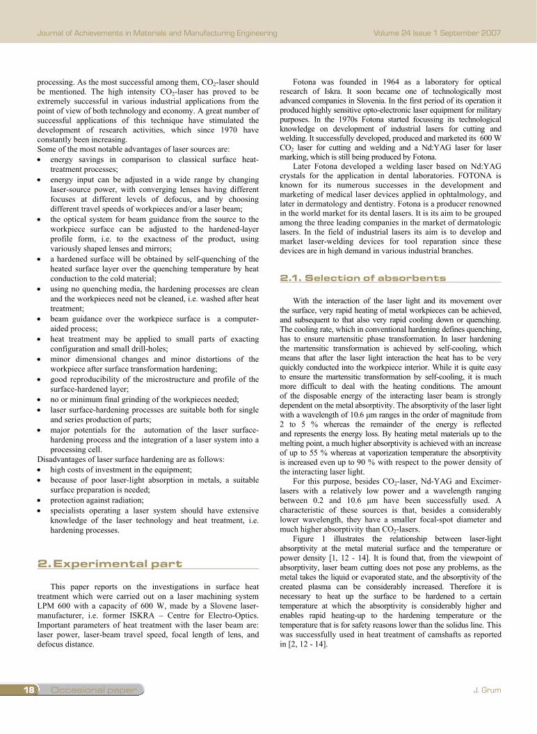
Figure 1 illustrates the relationship between laser-light absorptivity at the metal material surface and the temperature or power density [1, 12 - 14]. It is found that, from the viewpoint of absorptivity, laser beam cutting does not pose any problems, as the metal takes the liquid or evaporated state, and the absorptivity of the created plasma can be considerably increased. Therefore it is necessary to heat up the surface to be hardened to a certain temperature at which the absorptivity is considerably higher and enables rapid heating-up to the hardening temperature or the temperature that is for safety reasons lower than the solidus line. This was successfully used in heat treatment of camshafts as reported in [2, 12 - 14].
Fig. 1. Effect of temperature on laser-light absorptivity [1]
Another possibility of surface preparation is to apply an
absorbent. Additional coating consisting of an absorbent layer has to have the following properties: high capacity to absorb laser light; fast and easy application to metal surfaces; simple preparation and low cost; uniform spreading at the surface with a film thickness ranging
between 20 and 40 µm; high heat conductivity ensuring heat transfer to the base material; high adhesion to metal surfaces regardless of the deposition
method, e.g. submerging, spraying, painting; easy removal of the remainders from the surface.
Absorbents suitable for this kind of application are various
metal oxide powders, various carbides, graphite, zinc phosphate, manganese phosphate, and also black paint.
Testing of various absorbents. Absorptivity of various media was tested with an adapted calorimetric method as used by Borik in Giesen [3] for the determination of the laser-light absorption in the lenses used in lasers. By measuring the workpiece temperature and knowing the laser-beam power, with which the workpiece is treated, one can determine absorptivity (A) of the absorbent used. The temperature was measured with a thermocouple in the centre of C45E steel workpiece of 11 x 15 x 44 mm in size. Surface roughness Ra of the workpiece at the area of absorbent deposition amounted to 1.6 µm. Before the absorbent application the surface was degreased. The workpiece surfaces were coated with different types of purchased or home-made absorbents. In order to determine the absorptivity of each absorbent, the absorbent deposits had a thickness of 15 µm, except with a zinc-phosphate deposit where it amounted to 8 µm.
The following types of mainly home-made absorbents were compared: A) a mixture of graphite powder with a particle size of 1-2 µm
and ethanol in a ratio of 1 to 4; B) a mixture of graphite powder with an average particle size
of 1.4 µm and oxide powder Fe3O4 with an average particle size of 1.9 µm.
C) a mixture of graphite powder with an average particle size of 6 µm and ethanol;
D) a mixture of graphite powder with an average particle size of 6 µm and oxide powder Fe3O4 with an average particle size of 1.9 µm.
E) silicon-resin black paint with stability up to 600°C; F) silicon-resin colour paint with an addition of iron oxide Fe3O4
with an average particle size of 1.9 µm; G) an industrial spray, product of CRC Industries Europe NV,
with a trade name Graphit 33. H) a zinc-phosphate coating prepared with a thermal phosphate
bath of Zn3(PO)4)2.
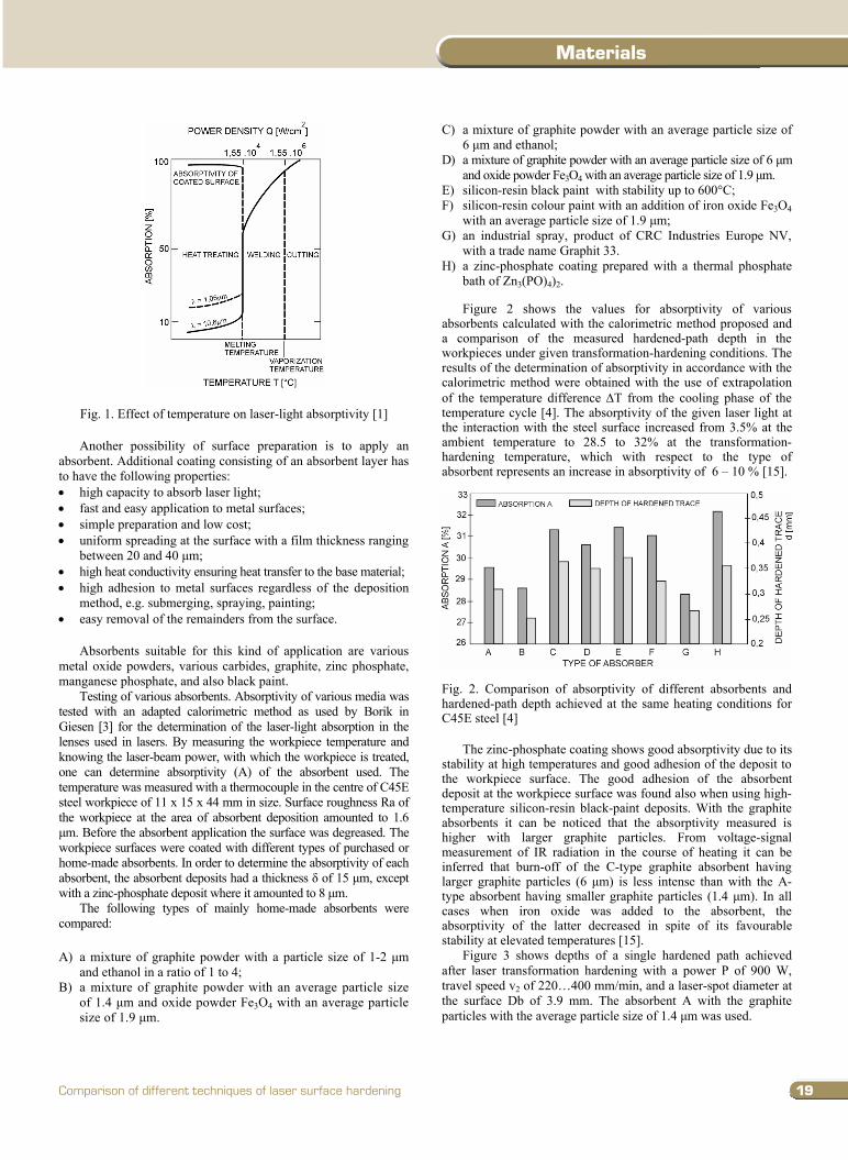
Figure 2 shows the values for absorptivity of various absorbents calculated with the calorimetric method proposed and a comparison of the measured hardened-path depth in the workpieces under given transformation-hardening conditions. The results of the determination of absorptivity in accordance with the calorimetric method were obtained with the use of extrapolation of the temperature difference T from the cooling phase of the temperature cycle [4]. The absorptivity of the given laser light at the interaction with the steel surface increased from 3.5% at the ambient temperature to 28.5 to 32% at the transformation-hardening temperature, which with respect to the type of absorbent represents an increase in absorptivity of 6 – 10 % [15].
Fig. 2. Comparison of absorptivity of different absorbents and hardened-path depth achieved at the same heating conditions for C45E steel [4]
The zinc-phosphate coating shows good absorptivity due to its
stability at high temperatures and good adhesion of the deposit to the workpiece surface. The good adhesion of the absorbent deposit at the workpiece surface was found also when using high-temperature silicon-resin black-paint deposits. With the graphite absorbents it can be noticed that the absorptivity measured is higher with larger graphite particles. From voltage-signal measurement of IR radiation in the course of heating it can be inferred that burn-off of the C-type graphite absorbent having larger graphite particles (6 µm) is less intense than with the A-type absorbent having smaller graphite particles (1.4 µm). In all cases when iron oxide was added to the absorbent, the absorptivity of the latter decreased in spite of its favourable stability at elevated temperatures [15].
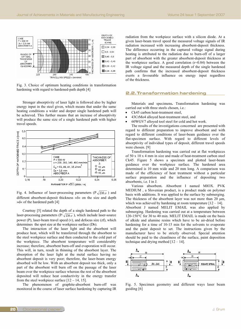
Figure 3 shows depths of a single hardened path achieved after laser transformation hardening with a power P of 900 W, travel speed v2 of 220…400 mm/min, and a laser-spot diameter at the surface Db of 3.9 mm. The absorbent A with the graphite particles with the average particle size of 1.4 µm was used.
2.Experimentalpart
2.1.selectionofabsorbents
19
Materials
Comparison of different techniques of laser surface hardening
processing. As the most successful among them, CO2-laser should be mentioned. The high intensity CO2-laser has proved to be extremely successful in various industrial applications from the point of view of both technology and economy. A great number of successful applications of this technique have stimulated the development of research activities, which since 1970 have constantly been increasing. Some of the most notable advantages of laser sources are:
energy savings in comparison to classical surface heat-treatment processes; energy input can be adjusted in a wide range by changing laser-source power, with converging lenses having different focuses at different levels of defocus, and by choosing different travel speeds of workpieces and/or a laser beam; the optical system for beam guidance from the source to the workpiece surface can be adjusted to the hardened-layer profile form, i.e. to the exactness of the product, using variously shaped lenses and mirrors; a hardened surface will be obtained by self-quenching of the heated surface layer over the quenching temperature by heat conduction to the cold material; using no quenching media, the hardening processes are clean and the workpieces need not be cleaned, i.e. washed after heat treatment; beam guidance over the workpiece surface is a computer-aided process; heat treatment may be applied to small parts of exacting configuration and small drill-holes; minor dimensional changes and minor distortions of the workpiece after surface transformation hardening; good reproducibility of the microstructure and profile of the surface-hardened layer; no or minimum final grinding of the workpieces needed; laser surface-hardening processes are suitable both for single and series production of parts; major potentials for the automation of the laser surface-hardening process and the integration of a laser system into a processing cell.
Disadvantages of laser surface hardening are as follows: high costs of investment in the equipment; because of poor laser-light absorption in metals, a suitable surface preparation is needed; protection against radiation; specialists operating a laser system should have extensive knowledge of the laser technology and heat treatment, i.e. hardening processes.
2. Experimental part This paper reports on the investigations in surface heat
treatment which were carried out on a laser machining system LPM 600 with a capacity of 600 W, made by a Slovene laser-manufacturer, i.e. former ISKRA – Centre for Electro-Optics. Important parameters of heat treatment with the laser beam are: laser power, laser-beam travel speed, focal length of lens, and defocus distance.
Fotona was founded in 1964 as a laboratory for optical research of Iskra. It soon became one of technologically most advanced companies in Slovenia. In the first period of its operation it produced highly sensitive opto-electronic laser equipment for military purposes. In the 1970s Fotona started focussing its technological knowledge on development of industrial lasers for cutting and welding. It successfully developed, produced and marketed its 600 W CO2 laser for cutting and welding and a Nd:YAG laser for laser marking, which is still being produced by Fotona.
Later Fotona developed a welding laser based on Nd:YAG crystals for the application in dental laboratories. FOTONA is known for its numerous successes in the development and marketing of medical laser devices applied in ophtalmology, and later in dermatology and dentistry. Fotona is a producer renowned in the world market for its dental lasers. It is its aim to be grouped among the three leading companies in the market of dermatologic lasers. In the field of industrial lasers its aim is to develop and market laser-welding devices for tool reparation since these devices are in high demand in various industrial branches.
2.1 Selection of Absorbents
With the interaction of the laser light and its movement over the surface, very rapid heating of metal workpieces can be achieved, and subsequent to that also very rapid cooling down or quenching. The cooling rate, which in conventional hardening defines quenching, has to ensure martensitic phase transformation. In laser hardening the martensitic transformation is achieved by self-cooling, which means that after the laser light interaction the heat has to be very quickly conducted into the workpiece interior. While it is quite easy to ensure the martensitic transformation by self-cooling, it is much more difficult to deal with the heating conditions. The amount of the disposable energy of the interacting laser beam is strongly dependent on the metal absorptivity. The absorptivity of the laser light with a wavelength of 10.6 µm ranges in the order of magnitude from 2 to 5 % whereas the remainder of the energy is reflected and represents the energy loss. By heating metal materials up to the melting point, a much higher absorptivity is achieved with an increase of up to 55 % whereas at vaporization temperature the absorptivity is increased even up to 90 % with respect to the power density of the interacting laser light.
For this purpose, besides CO2-laser, Nd-YAG and Excimer-lasers with a relatively low power and a wavelength ranging between 0.2 and 10.6 µm have been successfully used. A characteristic of these sources is that, besides a considerably lower wavelength, they have a smaller focal-spot diameter and much higher absorptivity than CO2-lasers.
Figure 1 illustrates the relationship between laser-light absorptivity at the metal material surface and the temperature or power density [1, 12 - 14]. It is found that, from the viewpoint of absorptivity, laser beam cutting does not pose any problems, as the metal takes the liquid or evaporated state, and the absorptivity of the created plasma can be considerably increased. Therefore it is necessary to heat up the surface to be hardened to a certain temperature at which the absorptivity is considerably higher and enables rapid heating-up to the hardening temperature or the temperature that is for safety reasons lower than the solidus line. This was successfully used in heat treatment of camshafts as reported in [2, 12 - 14].
Fig. 1. Effect of temperature on laser-light absorptivity [1]
Another possibility of surface preparation is to apply an
absorbent. Additional coating consisting of an absorbent layer has to have the following properties: high capacity to absorb laser light; fast and easy application to metal surfaces; simple preparation and low cost; uniform spreading at the surface with a film thickness ranging
between 20 and 40 µm; high heat conductivity ensuring heat transfer to the base material; high adhesion to metal surfaces regardless of the deposition
method, e.g. submerging, spraying, painting; easy removal of the remainders from the surface.
Absorbents suitable for this kind of application are various
metal oxide powders, various carbides, graphite, zinc phosphate, manganese phosphate, and also black paint.
Testing of various absorbents. Absorptivity of various media was tested with an adapted calorimetric method as used by Borik in Giesen [3] for the determination of the laser-light absorption in the lenses used in lasers. By measuring the workpiece temperature and knowing the laser-beam power, with which the workpiece is treated, one can determine absorptivity (A) of the absorbent used. The temperature was measured with a thermocouple in the centre of C45E steel workpiece of 11 x 15 x 44 mm in size. Surface roughness Ra of the workpiece at the area of absorbent deposition amounted to 1.6 µm. Before the absorbent application the surface was degreased. The workpiece surfaces were coated with different types of purchased or home-made absorbents. In order to determine the absorptivity of each absorbent, the absorbent deposits had a thickness of 15 µm, except with a zinc-phosphate deposit where it amounted to 8 µm.
The following types of mainly home-made absorbents were compared: A) a mixture of graphite powder with a particle size of 1-2 µm
and ethanol in a ratio of 1 to 4; B) a mixture of graphite powder with an average particle size
of 1.4 µm and oxide powder Fe3O4 with an average particle size of 1.9 µm.
C) a mixture of graphite powder with an average particle size of 6 µm and ethanol;
D) a mixture of graphite powder with an average particle size of 6 µm and oxide powder Fe3O4 with an average particle size of 1.9 µm.
E) silicon-resin black paint with stability up to 600°C; F) silicon-resin colour paint with an addition of iron oxide Fe3O4
with an average particle size of 1.9 µm; G) an industrial spray, product of CRC Industries Europe NV,
with a trade name Graphit 33. H) a zinc-phosphate coating prepared with a thermal phosphate
bath of Zn3(PO)4)2.
Figure 2 shows the values for absorptivity of various absorbents calculated with the calorimetric method proposed and a comparison of the measured hardened-path depth in the workpieces under given transformation-hardening conditions. The results of the determination of absorptivity in accordance with the calorimetric method were obtained with the use of extrapolation of the temperature difference T from the cooling phase of the temperature cycle [4]. The absorptivity of the given laser light at the interaction with the steel surface increased from 3.5% at the ambient temperature to 28.5 to 32% at the transformation-hardening temperature, which with respect to the type of absorbent represents an increase in absorptivity of 6 – 10 % [15].
Fig. 2. Comparison of absorptivity of different absorbents and hardened-path depth achieved at the same heating conditions for C45E steel [4]
The zinc-phosphate coating shows good absorptivity due to its
stability at high temperatures and good adhesion of the deposit to the workpiece surface. The good adhesion of the absorbent deposit at the workpiece surface was found also when using high-temperature silicon-resin black-paint deposits. With the graphite absorbents it can be noticed that the absorptivity measured is higher with larger graphite particles. From voltage-signal measurement of IR radiation in the course of heating it can be inferred that burn-off of the C-type graphite absorbent having larger graphite particles (6 µm) is less intense than with the A-type absorbent having smaller graphite particles (1.4 µm). In all cases when iron oxide was added to the absorbent, the absorptivity of the latter decreased in spite of its favourable stability at elevated temperatures [15].
Figure 3 shows depths of a single hardened path achieved after laser transformation hardening with a power P of 900 W, travel speed v2 of 220…400 mm/min, and a laser-spot diameter at the surface Db of 3.9 mm. The absorbent A with the graphite particles with the average particle size of 1.4 µm was used.
Occasional paper20
Journal of Achievements in Materials and Manufacturing Engineering
J. Grum
Volume 24 Issue 1 September 2007
Fig. 3. Choice of optimum heating conditions in transformation hardening with regard to hardened-path depth [4]
Stronger absorptivity of laser light is followed also by higher energy input in the steel given, which means that under the same heating conditions a wider and deeper single hardened path will be achieved. This further means that an increase of absorptivity will produce the same size of a single hardened path with higher travel speeds.
Fig. 4. Influence of laser-processing parameters (P vDb. ) and different absorbent-deposit thickness » « on the size and depth »d« of the hardened path [4]
Courtray [5] related the depth of a single hardened path to the laser-processing parameters (P/ vDb. ), which include laser-source power (P), laser-beam travel speed (v), and defocus size (zf), which determines the spot size at the workpiece surface (Db).
The interaction of the laser light and the absorbent will produce heat, which will be transferred through the absorbent to the steel workpiece surface and then conducted to the cold part of the workpiece. The absorbent temperature will considerably increase; therefore, absorbent burn-off and evaporation will occur. This will, in turn, result in thinning of the absorbent layer. The absorption of the laser light at the metal surface having no absorbent deposit is very poor; therefore, the laser-beam energy absorbed will be low. With an absorbent deposit too thick, only a part of the absorbent will burn off on the passage of the laser beam over the workpiece surface whereas the rest of the absorbent deposited will reduce heat conductivity in the energy transfer from the steel workpiece surface [12 – 14, 15].
The phenomenon of graphite-absorbent burn-off was monitored in the course of laser surface hardening by capturing IR
radiation from the workpiece surface with a silicon diode. At a given laser-beam travel speed the measured voltage signals of IR radiation increased with increasing absorbent-deposit thickness. The difference occurring in the captured voltage signal during heating is attributed to the radiation due to burn-off of a larger part of absorbent with the greater absorbent-deposit thickness at the workpiece surface. A good correlation (r=0.84) between the IR voltage signal and the measured depth of the single hardened path confirms that the increased absorbent-deposit thickness exerts a favourable influence on energy input regardless of the thickness. 2.2 Transformation hardening
Materials and specimens. Transformation hardening was carried out with three steels chosen, i.e.: Ck45 carbon heat-treatment steel, 43CrMo4 alloyed heat-treatment steel, and 60WGV7 alloyed tool steel for cold and hot work.
The results of the investigations concerned are presented with regard to different preparation to improve absorbent and with regard to different conditions of laser-beam guidance over the flat-specimen surface. With regard to different levels of absorptivity of individual types of deposit, different travel speeds were chosen. [9]
Transformation hardening was carried out at flat workpieces of 50 x 10 x 4 mm in size and made of heat-treatment carbon steel Ck45. Figure 5 shows a specimen and plotted laser-beam guidance over the workpiece surface. The hardened area determined is 10 mm wide and 20 mm long. A comparison was made of the efficiency of heat treatment without a particular surface preparation and the influence of depositing two absorbents, i.e. I in J.
Various absorbent. Absorbent I named MIOX. PVK MEDIUM , a Slovenian product, is a product made on polymer basis with additions. It was applied to the surface by submerging. The thickness of the absorbent layer was not more than 20 µm, which was achieved by hardening at room temperature [12 – 14]. Absorbent J named MELIT EMAIL was also applied by submerging. Hardening was carried out at a temperature between 120-150°C for 30 to 40 min. MELIT EMAIL is made on the basis of alkide and alumine resins which have to be air-dried before hardening for a time of 10-15 min for the solvents to evaporate and the paint deposit to set. The instructions given by the manufacturer have to be strictly observed. Special attention should be paid to the cleanliness of the surface, paint deposition technique and drying method [12 – 14].
Fig. 5. Specimen geometry and different ways laser beam guiding [6]
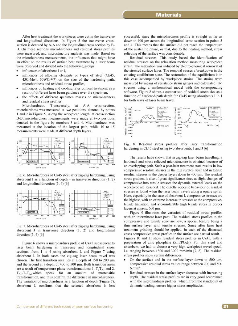
After heat treatment the workpieces were cut in the transverse and longitudinal directions. In Figure 5 the transverse cross-section is denoted by A-A and the longitudinal cross section by B-B. On these sections microhardness and residual stress profiles were measured, and microstructure analysis was made. Based on the microhardness measurements, the influences that might have an effect on the results of surface heat treatment by a laser beam were observed and divided into the following groups: influences of absorbent I or J, influences of alloying elements or types of steel (Ck45,
43CrMo4, 60WCrV7) on the size of the hardening path, microhardness and residual-stress profiles,
influences of heating and cooling rates on heat treatment as a result of different laser beam guidance over the specimen,
the effects of different specimen masses on microhardness and residual stress profiles. Microhardness. Transversely, at A-A cross-section,
microhardness was measured at two positions, denoted by points 1 and 2 in Figure 5. Along the workpiece length, at cross-section B-B, microhardness measurements were made at two positions denoted in the figure by numbers 3 and 4. Microhardness was measured at the location of the largest path, while 10 to 15 measurements were made at different depth layers.
Fig. 6. Microhardness of Ck45 steel after zig-zag hardening, using absorbent I as a function of depth – in transverse direction (1, 2) and longitudinal direction (3, 4) [6]
Fig. 7. Microhardness of Ck45 steel after zig-zag hardening, using absorbent J in transverse direction (1, 2) and longitudinal direction (3, 4) [6]
Figure 6 shows a microhardnes profile of Ck45 subsequent to laser beam hardening in transverse and longitudinal cross sections, from 1 to 4 using absorbent I, and Figure 7 using absorbent J. In both cases the zig-zag laser beam travel was chosen. The first transition area lies at a depth of 150 to 200 µm and the second at a depth of 400 to 500 µm. Both transition areas are a result of temperature phase transformations: 1. T TA3 and 2. TA1 T TAs,which speak for an amount of martensitic transformation, and thus confirm the difference in microhardness. The variation of microhardness as a function of depth (Figure 7), absorbent J, confirms that the selected absorbent is less
successful, since the microhardness profile is straight as far as down to 400 µm across the longitudinal cross section in points 3 and 4. This means that the surface did not reach the temperature of the austenitic phase, or that, due to the heating method, stress relieving of the surface was considerable.
Residual stresses. This study based the identification of residual stresses on the relaxation method measuring workpiece strain. The relaxation was induced by electro-chemical removal of the stressed surface layer. The removal causes a breakdown in the existing equilibrium state. The restoration of the equilibrium is in this case accompanied by workpiece strains. The strains were measured by means of resistance strain gauges and calculated into stresses using a mathematical model with the corresponding software. Figure 8 shows a comparison of residual stress size as a function of hardened-path depth for Ck45 using absorbents I in J for both ways of laser beam travel.
Fig. 8. Residual stress profiles after laser transformation hardening in Ck45 steel using two absorbents, I and J [6]
The results have shown that in zig-zag laser beam travelling, a hardened and stress relieved microstructure is obtained because of an overlapping path. Such a post-heat treatment state results in low compressive residual stresses in the thin surface layer and in tensile residual stresses in the deeper layers down to 400 µm. The residual stress gradient is also of great significance since at slight changes of compressive into tensile stresses the dynamic external loads on the workpiece are lessened. The exactly opposite behaviour of residual stresses is found when the laser beam travels along a square spiral. Here, especially in the case of absorbent I, compressive stresses are the highest, with an extreme increase in stresses at the compressive-tensile transition, and a considerably high tensile stress in deeper layers at approx. 600 µm.
Figure 9 illustrates the variation of residual stress profiles with an intermittent laser path. The residual stress profiles in the compressive and tensile zone are low, a special feature being a thin surface layer with tensile stresses. Since after laser heat treatment grinding should be applied, in each of the discussed cases compressive stress profiles in the surface are a usual result. Figures 10 and 11 show residual stress profiles in Ck45, with a preparation of zinc phosphate (Zn3(PO4)2). For this steel and absorbent, we had to choose a very high workpiece travel speed, i.e. ranging between 1800 and 3000 mm/min [7, 8]. The residual stress profiles show certain differences: On the surface and in the surface layer down to 500 µm,
compressive residual stress values range between 200 and 500 N/mm2.
Residual stresses in the surface layer decrease with increasing depth. The residual stress profiles are in very good accordance with the microhardness profiles, which, from the standpoint of dynamic loading, ensure higher stress amplitudes.
2.2.transformationhardening
21
Materials
Comparison of different techniques of laser surface hardening
Fig. 3. Choice of optimum heating conditions in transformation hardening with regard to hardened-path depth [4]
Stronger absorptivity of laser light is followed also by higher energy input in the steel given, which means that under the same heating conditions a wider and deeper single hardened path will be achieved. This further means that an increase of absorptivity will produce the same size of a single hardened path with higher travel speeds.
Fig. 4. Influence of laser-processing parameters (P vDb. ) and different absorbent-deposit thickness » « on the size and depth »d« of the hardened path [4]
Courtray [5] related the depth of a single hardened path to the laser-processing parameters (P/ vDb. ), which include laser-source power (P), laser-beam travel speed (v), and defocus size (zf), which determines the spot size at the workpiece surface (Db).
The interaction of the laser light and the absorbent will produce heat, which will be transferred through the absorbent to the steel workpiece surface and then conducted to the cold part of the workpiece. The absorbent temperature will considerably increase; therefore, absorbent burn-off and evaporation will occur. This will, in turn, result in thinning of the absorbent layer. The absorption of the laser light at the metal surface having no absorbent deposit is very poor; therefore, the laser-beam energy absorbed will be low. With an absorbent deposit too thick, only a part of the absorbent will burn off on the passage of the laser beam over the workpiece surface whereas the rest of the absorbent deposited will reduce heat conductivity in the energy transfer from the steel workpiece surface [12 – 14, 15].
The phenomenon of graphite-absorbent burn-off was monitored in the course of laser surface hardening by capturing IR
radiation from the workpiece surface with a silicon diode. At a given laser-beam travel speed the measured voltage signals of IR radiation increased with increasing absorbent-deposit thickness. The difference occurring in the captured voltage signal during heating is attributed to the radiation due to burn-off of a larger part of absorbent with the greater absorbent-deposit thickness at the workpiece surface. A good correlation (r=0.84) between the IR voltage signal and the measured depth of the single hardened path confirms that the increased absorbent-deposit thickness exerts a favourable influence on energy input regardless of the thickness. 2.2 Transformation hardening
Materials and specimens. Transformation hardening was carried out with three steels chosen, i.e.: Ck45 carbon heat-treatment steel, 43CrMo4 alloyed heat-treatment steel, and 60WGV7 alloyed tool steel for cold and hot work.
The results of the investigations concerned are presented with regard to different preparation to improve absorbent and with regard to different conditions of laser-beam guidance over the flat-specimen surface. With regard to different levels of absorptivity of individual types of deposit, different travel speeds were chosen. [9]
Transformation hardening was carried out at flat workpieces of 50 x 10 x 4 mm in size and made of heat-treatment carbon steel Ck45. Figure 5 shows a specimen and plotted laser-beam guidance over the workpiece surface. The hardened area determined is 10 mm wide and 20 mm long. A comparison was made of the efficiency of heat treatment without a particular surface preparation and the influence of depositing two absorbents, i.e. I in J.
Various absorbent. Absorbent I named MIOX. PVK MEDIUM , a Slovenian product, is a product made on polymer basis with additions. It was applied to the surface by submerging. The thickness of the absorbent layer was not more than 20 µm, which was achieved by hardening at room temperature [12 – 14]. Absorbent J named MELIT EMAIL was also applied by submerging. Hardening was carried out at a temperature between 120-150°C for 30 to 40 min. MELIT EMAIL is made on the basis of alkide and alumine resins which have to be air-dried before hardening for a time of 10-15 min for the solvents to evaporate and the paint deposit to set. The instructions given by the manufacturer have to be strictly observed. Special attention should be paid to the cleanliness of the surface, paint deposition technique and drying method [12 – 14].
Fig. 5. Specimen geometry and different ways laser beam guiding [6]
After heat treatment the workpieces were cut in the transverse and longitudinal directions. In Figure 5 the transverse cross-section is denoted by A-A and the longitudinal cross section by B-B. On these sections microhardness and residual stress profiles were measured, and microstructure analysis was made. Based on the microhardness measurements, the influences that might have an effect on the results of surface heat treatment by a laser beam were observed and divided into the following groups: influences of absorbent I or J, influences of alloying elements or types of steel (Ck45,
43CrMo4, 60WCrV7) on the size of the hardening path, microhardness and residual-stress profiles,
influences of heating and cooling rates on heat treatment as a result of different laser beam guidance over the specimen,
the effects of different specimen masses on microhardness and residual stress profiles. Microhardness. Transversely, at A-A cross-section,
microhardness was measured at two positions, denoted by points 1 and 2 in Figure 5. Along the workpiece length, at cross-section B-B, microhardness measurements were made at two positions denoted in the figure by numbers 3 and 4. Microhardness was measured at the location of the largest path, while 10 to 15 measurements were made at different depth layers.
Fig. 6. Microhardness of Ck45 steel after zig-zag hardening, using absorbent I as a function of depth – in transverse direction (1, 2) and longitudinal direction (3, 4) [6]
Fig. 7. Microhardness of Ck45 steel after zig-zag hardening, using absorbent J in transverse direction (1, 2) and longitudinal direction (3, 4) [6]
Figure 6 shows a microhardnes profile of Ck45 subsequent to laser beam hardening in transverse and longitudinal cross sections, from 1 to 4 using absorbent I, and Figure 7 using absorbent J. In both cases the zig-zag laser beam travel was chosen. The first transition area lies at a depth of 150 to 200 µm and the second at a depth of 400 to 500 µm. Both transition areas are a result of temperature phase transformations: 1. T TA3 and 2. TA1 T TAs,which speak for an amount of martensitic transformation, and thus confirm the difference in microhardness. The variation of microhardness as a function of depth (Figure 7), absorbent J, confirms that the selected absorbent is less
successful, since the microhardness profile is straight as far as down to 400 µm across the longitudinal cross section in points 3 and 4. This means that the surface did not reach the temperature of the austenitic phase, or that, due to the heating method, stress relieving of the surface was considerable.
Residual stresses. This study based the identification of residual stresses on the relaxation method measuring workpiece strain. The relaxation was induced by electro-chemical removal of the stressed surface layer. The removal causes a breakdown in the existing equilibrium state. The restoration of the equilibrium is in this case accompanied by workpiece strains. The strains were measured by means of resistance strain gauges and calculated into stresses using a mathematical model with the corresponding software. Figure 8 shows a comparison of residual stress size as a function of hardened-path depth for Ck45 using absorbents I in J for both ways of laser beam travel.
Fig. 8. Residual stress profiles after laser transformation hardening in Ck45 steel using two absorbents, I and J [6]
The results have shown that in zig-zag laser beam travelling, a hardened and stress relieved microstructure is obtained because of an overlapping path. Such a post-heat treatment state results in low compressive residual stresses in the thin surface layer and in tensile residual stresses in the deeper layers down to 400 µm. The residual stress gradient is also of great significance since at slight changes of compressive into tensile stresses the dynamic external loads on the workpiece are lessened. The exactly opposite behaviour of residual stresses is found when the laser beam travels along a square spiral. Here, especially in the case of absorbent I, compressive stresses are the highest, with an extreme increase in stresses at the compressive-tensile transition, and a considerably high tensile stress in deeper layers at approx. 600 µm.
Figure 9 illustrates the variation of residual stress profiles with an intermittent laser path. The residual stress profiles in the compressive and tensile zone are low, a special feature being a thin surface layer with tensile stresses. Since after laser heat treatment grinding should be applied, in each of the discussed cases compressive stress profiles in the surface are a usual result. Figures 10 and 11 show residual stress profiles in Ck45, with a preparation of zinc phosphate (Zn3(PO4)2). For this steel and absorbent, we had to choose a very high workpiece travel speed, i.e. ranging between 1800 and 3000 mm/min [7, 8]. The residual stress profiles show certain differences: On the surface and in the surface layer down to 500 µm,
compressive residual stress values range between 200 and 500 N/mm2.
Residual stresses in the surface layer decrease with increasing depth. The residual stress profiles are in very good accordance with the microhardness profiles, which, from the standpoint of dynamic loading, ensure higher stress amplitudes.
Occasional paper22
Journal of Achievements in Materials and Manufacturing Engineering
J. Grum
Volume 24 Issue 1 September 2007
Residual stresses are restricted to their compressive nature in the surface layer and do not show any notable tendencies to change into tensile stresses.
Residual stress profiles do not differ much with respect to the chosen laser beam path across the workpiece.
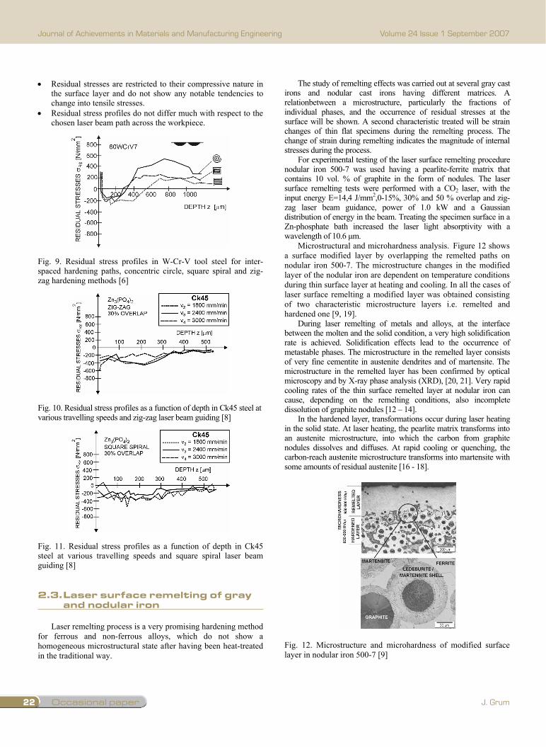
Fig. 9. Residual stress profiles in W-Cr-V tool steel for inter-spaced hardening paths, concentric circle, square spiral and zig-zag hardening methods [6]
Fig. 10. Residual stress profiles as a function of depth in Ck45 steel at various travelling speeds and zig-zag laser beam guiding [8]
Fig. 11. Residual stress profiles as a function of depth in Ck45 steel at various travelling speeds and square spiral laser beam guiding [8] 2.3 Laser surface remelting of gray and nodular iron
Laser remelting process is a very promising hardening method for ferrous and non-ferrous alloys, which do not show a homogeneous microstructural state after having been heat-treated in the traditional way.
The study of remelting effects was carried out at several gray cast irons and nodular cast irons having different matrices. A relationbetween a microstructure, particularly the fractions of individual phases, and the occurrence of residual stresses at the surface will be shown. A second characteristic treated will be strain changes of thin flat specimens during the remelting process. The change of strain during remelting indicates the magnitude of internal stresses during the process.
For experimental testing of the laser surface remelting procedure nodular iron 500-7 was used having a pearlite-ferrite matrix that contains 10 vol. % of graphite in the form of nodules. The laser surface remelting tests were performed with a CO2 laser, with the input energy E=14,4 J/mm2,0-15%, 30% and 50 % overlap and zig-zag laser beam guidance, power of 1.0 kW and a Gaussian distribution of energy in the beam. Treating the specimen surface in a Zn-phosphate bath increased the laser light absorptivity with a wavelength of 10.6 µm.
Microstructural and microhardness analysis. Figure 12 shows a surface modified layer by overlapping the remelted paths on nodular iron 500-7. The microstructure changes in the modified layer of the nodular iron are dependent on temperature conditions during thin surface layer at heating and cooling. In all the cases of laser surface remelting a modified layer was obtained consisting of two characteristic microstructure layers i.e. remelted and hardened one [9, 19].
During laser remelting of metals and alloys, at the interface between the molten and the solid condition, a very high solidification rate is achieved. Solidification effects lead to the occurrence of metastable phases. The microstructure in the remelted layer consists of very fine cementite in austenite dendrites and of martensite. The microstructure in the remelted layer has been confirmed by optical microscopy and by X-ray phase analysis (XRD), [20, 21]. Very rapid cooling rates of the thin surface remelted layer at nodular iron can cause, depending on the remelting conditions, also incomplete dissolution of graphite nodules [12 – 14].
In the hardened layer, transformations occur during laser heating in the solid state. At laser heating, the pearlite matrix transforms into an austenite microstructure, into which the carbon from graphite nodules dissolves and diffuses. At rapid cooling or quenching, the carbon-reach austenite microstructure transforms into martensite with some amounts of residual austenite [16 - 18].
Fig. 12. Microstructure and microhardness of modified surface layer in nodular iron 500-7 [9]
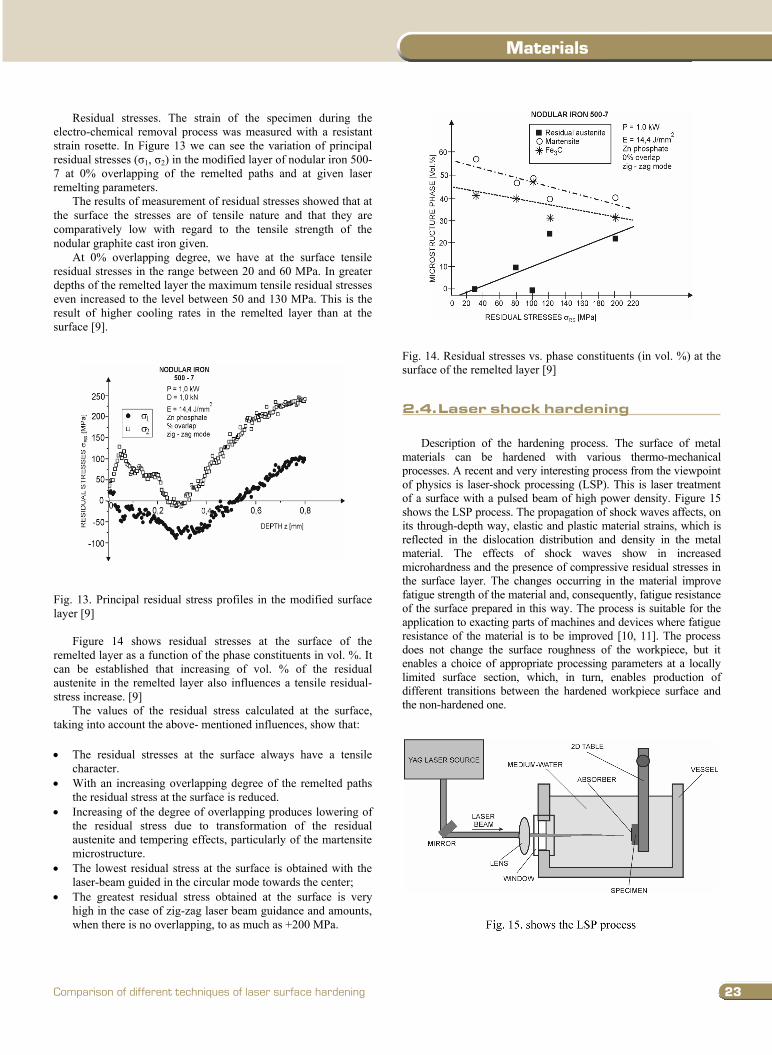
Residual stresses. The strain of the specimen during the electro-chemical removal process was measured with a resistant strain rosette. In Figure 13 we can see the variation of principal residual stresses ( 1, 2) in the modified layer of nodular iron 500-7 at 0% overlapping of the remelted paths and at given laser remelting parameters.
The results of measurement of residual stresses showed that at the surface the stresses are of tensile nature and that they are comparatively low with regard to the tensile strength of the nodular graphite cast iron given.
At 0% overlapping degree, we have at the surface tensile residual stresses in the range between 20 and 60 MPa. In greater depths of the remelted layer the maximum tensile residual stresses even increased to the level between 50 and 130 MPa. This is the result of higher cooling rates in the remelted layer than at the surface [9].
Fig. 13. Principal residual stress profiles in the modified surface layer [9]
Figure 14 shows residual stresses at the surface of the remelted layer as a function of the phase constituents in vol. %. It can be established that increasing of vol. % of the residual austenite in the remelted layer also influences a tensile residual-stress increase. [9]
The values of the residual stress calculated at the surface, taking into account the above- mentioned influences, show that: The residual stresses at the surface always have a tensile
character. With an increasing overlapping degree of the remelted paths
the residual stress at the surface is reduced. Increasing of the degree of overlapping produces lowering of
the residual stress due to transformation of the residual austenite and tempering effects, particularly of the martensite microstructure.
The lowest residual stress at the surface is obtained with the laser-beam guided in the circular mode towards the center;
The greatest residual stress obtained at the surface is very high in the case of zig-zag laser beam guidance and amounts, when there is no overlapping, to as much as +200 MPa.
Fig. 14. Residual stresses vs. phase constituents (in vol. %) at the surface of the remelted layer [9]
2.4 Laser shock hardening
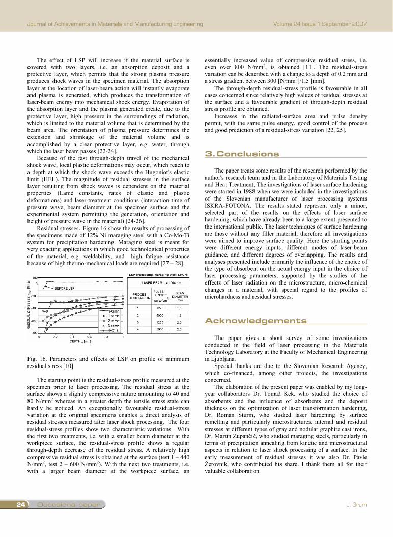
Description of the hardening process. The surface of metal materials can be hardened with various thermo-mechanical processes. A recent and very interesting process from the viewpoint of physics is laser-shock processing (LSP). This is laser treatment of a surface with a pulsed beam of high power density. Figure 15 shows the LSP process. The propagation of shock waves affects, on its through-depth way, elastic and plastic material strains, which is reflected in the dislocation distribution and density in the metal material. The effects of shock waves show in increased microhardness and the presence of compressive residual stresses in the surface layer. The changes occurring in the material improve fatigue strength of the material and, consequently, fatigue resistance of the surface prepared in this way. The process is suitable for the application to exacting parts of machines and devices where fatigue resistance of the material is to be improved [10, 11]. The process does not change the surface roughness of the workpiece, but it enables a choice of appropriate processing parameters at a locally limited surface section, which, in turn, enables production of different transitions between the hardened workpiece surface and the non-hardened one.
Fig. 15. shows the LSP process
2.3.Lasersurfaceremeltingofgrayandnodulariron
23
Materials
Comparison of different techniques of laser surface hardening
Residual stresses are restricted to their compressive nature in the surface layer and do not show any notable tendencies to change into tensile stresses.
Residual stress profiles do not differ much with respect to the chosen laser beam path across the workpiece.
Fig. 9. Residual stress profiles in W-Cr-V tool steel for inter-spaced hardening paths, concentric circle, square spiral and zig-zag hardening methods [6]
Fig. 10. Residual stress profiles as a function of depth in Ck45 steel at various travelling speeds and zig-zag laser beam guiding [8]
Fig. 11. Residual stress profiles as a function of depth in Ck45 steel at various travelling speeds and square spiral laser beam guiding [8] 2.3 Laser surface remelting of gray and nodular iron
Laser remelting process is a very promising hardening method for ferrous and non-ferrous alloys, which do not show a homogeneous microstructural state after having been heat-treated in the traditional way.
The study of remelting effects was carried out at several gray cast irons and nodular cast irons having different matrices. A relationbetween a microstructure, particularly the fractions of individual phases, and the occurrence of residual stresses at the surface will be shown. A second characteristic treated will be strain changes of thin flat specimens during the remelting process. The change of strain during remelting indicates the magnitude of internal stresses during the process.
For experimental testing of the laser surface remelting procedure nodular iron 500-7 was used having a pearlite-ferrite matrix that contains 10 vol. % of graphite in the form of nodules. The laser surface remelting tests were performed with a CO2 laser, with the input energy E=14,4 J/mm2,0-15%, 30% and 50 % overlap and zig-zag laser beam guidance, power of 1.0 kW and a Gaussian distribution of energy in the beam. Treating the specimen surface in a Zn-phosphate bath increased the laser light absorptivity with a wavelength of 10.6 µm.
Microstructural and microhardness analysis. Figure 12 shows a surface modified layer by overlapping the remelted paths on nodular iron 500-7. The microstructure changes in the modified layer of the nodular iron are dependent on temperature conditions during thin surface layer at heating and cooling. In all the cases of laser surface remelting a modified layer was obtained consisting of two characteristic microstructure layers i.e. remelted and hardened one [9, 19].
During laser remelting of metals and alloys, at the interface between the molten and the solid condition, a very high solidification rate is achieved. Solidification effects lead to the occurrence of metastable phases. The microstructure in the remelted layer consists of very fine cementite in austenite dendrites and of martensite. The microstructure in the remelted layer has been confirmed by optical microscopy and by X-ray phase analysis (XRD), [20, 21]. Very rapid cooling rates of the thin surface remelted layer at nodular iron can cause, depending on the remelting conditions, also incomplete dissolution of graphite nodules [12 – 14].
In the hardened layer, transformations occur during laser heating in the solid state. At laser heating, the pearlite matrix transforms into an austenite microstructure, into which the carbon from graphite nodules dissolves and diffuses. At rapid cooling or quenching, the carbon-reach austenite microstructure transforms into martensite with some amounts of residual austenite [16 - 18].
Fig. 12. Microstructure and microhardness of modified surface layer in nodular iron 500-7 [9]
Residual stresses. The strain of the specimen during the electro-chemical removal process was measured with a resistant strain rosette. In Figure 13 we can see the variation of principal residual stresses ( 1, 2) in the modified layer of nodular iron 500-7 at 0% overlapping of the remelted paths and at given laser remelting parameters.
The results of measurement of residual stresses showed that at the surface the stresses are of tensile nature and that they are comparatively low with regard to the tensile strength of the nodular graphite cast iron given.
At 0% overlapping degree, we have at the surface tensile residual stresses in the range between 20 and 60 MPa. In greater depths of the remelted layer the maximum tensile residual stresses even increased to the level between 50 and 130 MPa. This is the result of higher cooling rates in the remelted layer than at the surface [9].
Fig. 13. Principal residual stress profiles in the modified surface layer [9]
Figure 14 shows residual stresses at the surface of the remelted layer as a function of the phase constituents in vol. %. It can be established that increasing of vol. % of the residual austenite in the remelted layer also influences a tensile residual-stress increase. [9]
The values of the residual stress calculated at the surface, taking into account the above- mentioned influences, show that: The residual stresses at the surface always have a tensile
character. With an increasing overlapping degree of the remelted paths
the residual stress at the surface is reduced. Increasing of the degree of overlapping produces lowering of
the residual stress due to transformation of the residual austenite and tempering effects, particularly of the martensite microstructure.
The lowest residual stress at the surface is obtained with the laser-beam guided in the circular mode towards the center;
The greatest residual stress obtained at the surface is very high in the case of zig-zag laser beam guidance and amounts, when there is no overlapping, to as much as +200 MPa.
Fig. 14. Residual stresses vs. phase constituents (in vol. %) at the surface of the remelted layer [9]
2.4 Laser shock hardening
Description of the hardening process. The surface of metal materials can be hardened with various thermo-mechanical processes. A recent and very interesting process from the viewpoint of physics is laser-shock processing (LSP). This is laser treatment of a surface with a pulsed beam of high power density. Figure 15 shows the LSP process. The propagation of shock waves affects, on its through-depth way, elastic and plastic material strains, which is reflected in the dislocation distribution and density in the metal material. The effects of shock waves show in increased microhardness and the presence of compressive residual stresses in the surface layer. The changes occurring in the material improve fatigue strength of the material and, consequently, fatigue resistance of the surface prepared in this way. The process is suitable for the application to exacting parts of machines and devices where fatigue resistance of the material is to be improved [10, 11]. The process does not change the surface roughness of the workpiece, but it enables a choice of appropriate processing parameters at a locally limited surface section, which, in turn, enables production of different transitions between the hardened workpiece surface and the non-hardened one.
Fig. 15. shows the LSP process
2.4.Lasershockhardening
Occasional paper24
Journal of Achievements in Materials and Manufacturing Engineering
J. Grum
Volume 24 Issue 1 September 2007
The effect of LSP will increase if the material surface is covered with two layers, i.e. an absorption deposit and a protective layer, which permits that the strong plasma pressure produces shock waves in the specimen material. The absorption layer at the location of laser-beam action will instantly evaporate and plasma is generated, which produces the transformation of laser-beam energy into mechanical shock energy. Evaporation of the absorption layer and the plasma generated create, due to the protective layer, high pressure in the surroundings of radiation, which is limited to the material volume that is determined by the beam area. The orientation of plasma pressure determines the extension and shrinkage of the material volume and is accomplished by a clear protective layer, e.g. water, through which the laser beam passes [22-24].
Because of the fast through-depth travel of the mechanical shock wave, local plastic deformations may occur, which reach to a depth at which the shock wave exceeds the Hugoniot's elastic limit (HEL). The magnitude of residual stresses in the surface layer resulting from shock waves is dependent on the material properties (Lamé constants, rates of elastic and plastic deformations) and laser-treatment conditions (interaction time of pressure wave, beam diameter at the specimen surface and the experimental system permitting the generation, orientation and height of pressure wave in the material) [24-26].
Residual stresses. Figure 16 show the results of processing of the specimens made of 12% Ni maraging steel with a Co-Mo-Ti system for precipitation hardening. Maraging steel is meant for very exacting applications in which good technological properties of the material, e.g. weldability, and high fatigue resistance because of high thermo-mechanical loads are required [27 – 28].
Fig. 16. Parameters and effects of LSP on profile of minimum residual stress [10]
The starting point is the residual-stress profile measured at the specimen prior to laser processing. The residual stress at the surface shows a slightly compressive nature amounting to 40 and 80 N/mm2 whereas in a greater depth the tensile stress state can hardly be noticed. An exceptionally favourable residual-stress variation at the original specimens enables a direct analysis of residual stresses measured after laser shock processing. The four residual-stress profiles show two characteristic variations. With the first two treatments, i.e. with a smaller beam diameter at the workpiece surface, the residual-stress profile shows a regular through-depth decrease of the residual stress. A relatively high compressive residual stress is obtained at the surface (test 1 – 440 N/mm2, test 2 – 600 N/mm2). With the next two treatments, i.e. with a larger beam diameter at the workpiece surface, an
essentially increased value of compressive residual stress, i.e. even over 800 N/mm2, is obtained [11]. The residual-stress variation can be described with a change to a depth of 0.2 mm and a stress gradient between 300 [N/mm2]/1,5 [mm].
The through-depth residual-stress profile is favourable in all cases concerned since relatively high values of residual stresses at the surface and a favourable gradient of through-depth residual stress profile are obtained.
Increases in the radiated-surface area and pulse density permit, with the same pulse energy, good control of the process and good prediction of a residual-stress variation [22, 25]. 3. Conclusions
The paper treats some results of the research performed by the author's research team and in the Laboratory of Materials Testing and Heat Treatment, The investigations of laser surface hardening were started in 1988 when we were included in the investigations of the Slovenian manufacturer of laser processing systems ISKRA-FOTONA. The results stated represent only a minor, selected part of the results on the effects of laser surface hardening, which have already been to a large extent presented to the international public. The laser techniques of surface hardening are those without any filler material, therefore all investigations were aimed to improve surface quality. Here the starting points were different energy inputs, different modes of laser-beam guidance, and different degrees of overlapping. The results and analyses presented include primarily the influence of the choice of the type of absorbent on the actual energy input in the choice of laser processing parameters, supported by the studies of the effects of laser radiation on the microstructure, micro-chemical changes in a material, with special regard to the profiles of microhardness and residual stresses. Acknowledgements
The paper gives a short survey of some investigations conducted in the field of laser processing in the Materials Technology Laboratory at the Faculty of Mechanical Engineering in Ljubljana.
Special thanks are due to the Slovenian Research Agency, which co-financed, among other projects, the investigations concerned.
The elaboration of the present paper was enabled by my long-year collaborators Dr. Tomaž Kek, who studied the choice of absorbents and the influence of absorbents and the deposit thickness on the optimization of laser transformation hardening, Dr. Roman Šturm, who studied laser hardening by surface remelting and particularly microstructures, internal and residual stresses at different types of gray and nodular graphite cast irons, Dr. Martin Zupan i , who studied maraging steels, particularly in terms of precipitation annealing from kinetic and microstructural aspects in relation to laser shock processing of a surface. In the early measurement of residual stresses it was also Dr. Pavle Žerovnik, who contributed his share. I thank them all for their valuable collaboration.
Special thanks are due to Prof. Dr. J. Ocana and the collaborators of the Laser Centre in Madrid, with whom we have had an excellent collaboration in the field of laser alloying of surface layers for surface refinement and laser shock processing of surfaces for many years. This excellent collaboration has been confirmed by numerous joint publications.
I am also very thankful to the organizers of the present Conference, who invited me to present the work and results achieved by my research team within the Laboratory for Metals Testing and Heat Treatment.
References [1] S.L. Engel, Basic of Laser Heat Treating, Source book on
Applications of the Laser in Metalworking, American Society for Metals, Ed.: E.A. Metzbower, Metals Park (1981) 149-171.
[2] H. Szengel, S. Mordike, H.B. Pruel, Laser Oberflaechenbehandlung-eineProduktionsreifes Verfahren fuer Vielfaeltige Anwendungen, International Conference, In New Technologies of Metals Heat Treatment, Croatian Society for Heat Treatment; Conference Proceeding, Zagreb, Croatia, 1990, 1-12.
[3] S. Borik, A. Gieser, Finite Element Analysis of the Transient Behavior of Optical Components under Irradiation, Laser-Induced Damage in Optical Materials, Proceedings of the SPIE 1441 (1990) 420-429.
[4] T. Kek, The Influence of Different Conditions in Laser-Beam Interaction in Laser Surface Hardening of Steels, MSc. Thesis, University of Ljubljana, 2003 40-17 (in Slovenian).
[5] C. Courtney, W.M. Steen, The Surface Heat Treatment of Engineering Steel using a 2 kW CO2 Laser, 195-208, Basic of Laser Heat Treating, Source book on Applications of the Laser in Metalworking, American Society for Metals, Ed.: E.A. Metzbower, Metals Park (1981) 149-171.
[6] J. Grum, P. Žerovnik, Residual Stresses in Laser Heat Treatment of Plane Surfaces, Proceedings of the First International Conference on Quenching and Control of Distortion (1992) 333-341.
[7] J. Grum, P. Žerovnik, Laser Hardening of Steels-Part 1, Heat Treating (1993) 16-20.
[8] J. Grum, P. Žerovnik, Laser Hardening of Steels-Part 2, Heat Treating (1993) 32-36.
[9] J. Grum, R. Šturm, Microstructure variations in the laser surface remelted layer of nodular iron, International Journal of Microstructure and Materials Properties 1 (2005) 11-23.
[10] M. Zupan i , Precipitation hardening and properties of a maraging steel (in Slovene), Ph.D. Thesis, Faculty of Mechanical Engineering, University of Ljubljana, 2005.
[11] J. Grum, M. Zupan i , J. L. Ocana, Laser Shock Processing of the Maraging Steel Surface, Materials Science Forum 537-538 (2007) 655-662.
[12] J. Grum, Laser surface hardening. Eds.: G.E. Totten, K. Funatani, L. Xie, Handbook of metallurgical process design, New York, 2004 641-731.
[13] J. Grum, Laser surface hardening. Eds. G.E. Totten, Steel heat treatment, equipment and process design. 2nd ed. Boca Raton, Taylor and Francis (2007) 435-566.
[14] J. Grum, Laser surface hardening, Materials science and technology series 2 (2002).
[15] J. Grum, T. Kek, The influence of different conditions of laser-beam interaction in laser surface hardening of steels, Thin Solid Films 453-454 (2004) 94-99.
[16] J. Grum, R. Šturm, Influence of laser beam guiding and overlapping on residual stress in remelting process, Surface Engineering 21 (2005) 27-34.
[17] J. Grum R. Šturm, Influence of laser surface melt-hardening conditions on residual stresses in thin plates, Surface Coating Technology 100-101 (1998) 455-458.
[18] J. Grum R. Šturm, Residual stress profiles of the laser surface remelted nodular irons, Materials Science Forum 490-491 (2005) 460-468.
[19] J. Grum, J.M. Slabe, The state of differently heat-treated 12% Ni maraging steel after laser remelting, Materials Science Forum 537-538 (2007) 647-654.
[20] L.A. Dobrza ski, M. Bonek, E. Hajduczek, A. Klimpel, A. Lisiecki, Comparison of the structures of the hot-work tool steels laser modified surface layers, Journal of Materials Processing Technology 164-165 (2005) 1014-1024.
[21] Z. Liu, P.H. Chong, P. Skeldon, P.A. Hilton, J.T. Spencer, B. Quayle, Fundamental understanding of the corrosion performance of laser-melted metallic alloys, Surface and Coatings Technology 200 (2006) 5514-5525.
[22] C. Rubio-Gonzalez, G. Gomez-Rosas, J.L. Ocana, C. Molpeceres, A. Banderas, J. Porro, M. Morales, Effect of an absorbent overlay on the residual stress field induced by laser shock processing on aluminum samples, Applied Surface Science 252 (2006) 6201-6205.
[23] J.H. Abbouda, K.Y. Benyounis, A.G. Olabi, M.S.J. Hashmic, Laser surface treatments of iron-based substrates for automotive application, Journal of Materials Processing Technology 182 (2007) 427-431.
[24] U. Sanchez-Santana, C. Rubio-Gonz´alez, G. Gomez-Rosas, J.L. Ocana, C. Molpeceres, J. Porro, M. Morales, Wear and friction of 6061-T6 aluminum alloy treated by laser shock processing, Wear 260 (2006) 847-854.
[25] G. Gomez-Rosas, C. Rubio-Gonzalez, J.L Ocana, C. Molpeceres, J.A. Porro, W. Chi-Moreno, M. Morales, High level compressive residual stresses produced in aluminum alloys by laser shock processing, Applied Surface Science 252 (2005) 883–887.
[26] C. Rubio-Gonzalez, J.L. Ocana, G. Gomez-Rosas, C. Molpeceres, M. Paredesa, A. Banderas, J. Porro, M. Morales, Effect of laser shock processing on fatigue crack growth and fracture toughness of 6061-T6 aluminum alloy, Materials Science and Engineering A 386 (2004) 291–295.
[27] J. Grum, M. Zupan i , Suitability assessment of replacement of conventional hot-working steels with maraging steel, Part 1, Mechanical properties of maraging steel after precipitation hardening treatment, Zeitschrift für Metallkunde 93/2 (2002) 164-170.
[28] J. Grum, M. Zupan i , Suitability assessment of replacement of conventional hot-working steels with maraging steel, Part 2, Microstructure of maraging steel after precipitation hardening treatment, Zeitschrift für Metallkunde 93/2 (2002) 171-176.
3.conclusions
Acknowledgements
25READING DIRECT: www.journalamme.org
Materials
The effect of LSP will increase if the material surface is covered with two layers, i.e. an absorption deposit and a protective layer, which permits that the strong plasma pressure produces shock waves in the specimen material. The absorption layer at the location of laser-beam action will instantly evaporate and plasma is generated, which produces the transformation of laser-beam energy into mechanical shock energy. Evaporation of the absorption layer and the plasma generated create, due to the protective layer, high pressure in the surroundings of radiation, which is limited to the material volume that is determined by the beam area. The orientation of plasma pressure determines the extension and shrinkage of the material volume and is accomplished by a clear protective layer, e.g. water, through which the laser beam passes [22-24].
Because of the fast through-depth travel of the mechanical shock wave, local plastic deformations may occur, which reach to a depth at which the shock wave exceeds the Hugoniot's elastic limit (HEL). The magnitude of residual stresses in the surface layer resulting from shock waves is dependent on the material properties (Lamé constants, rates of elastic and plastic deformations) and laser-treatment conditions (interaction time of pressure wave, beam diameter at the specimen surface and the experimental system permitting the generation, orientation and height of pressure wave in the material) [24-26].
Residual stresses. Figure 16 show the results of processing of the specimens made of 12% Ni maraging steel with a Co-Mo-Ti system for precipitation hardening. Maraging steel is meant for very exacting applications in which good technological properties of the material, e.g. weldability, and high fatigue resistance because of high thermo-mechanical loads are required [27 – 28].
Fig. 16. Parameters and effects of LSP on profile of minimum residual stress [10]
The starting point is the residual-stress profile measured at the specimen prior to laser processing. The residual stress at the surface shows a slightly compressive nature amounting to 40 and 80 N/mm2 whereas in a greater depth the tensile stress state can hardly be noticed. An exceptionally favourable residual-stress variation at the original specimens enables a direct analysis of residual stresses measured after laser shock processing. The four residual-stress profiles show two characteristic variations. With the first two treatments, i.e. with a smaller beam diameter at the workpiece surface, the residual-stress profile shows a regular through-depth decrease of the residual stress. A relatively high compressive residual stress is obtained at the surface (test 1 – 440 N/mm2, test 2 – 600 N/mm2). With the next two treatments, i.e. with a larger beam diameter at the workpiece surface, an
essentially increased value of compressive residual stress, i.e. even over 800 N/mm2, is obtained [11]. The residual-stress variation can be described with a change to a depth of 0.2 mm and a stress gradient between 300 [N/mm2]/1,5 [mm].
The through-depth residual-stress profile is favourable in all cases concerned since relatively high values of residual stresses at the surface and a favourable gradient of through-depth residual stress profile are obtained.
Increases in the radiated-surface area and pulse density permit, with the same pulse energy, good control of the process and good prediction of a residual-stress variation [22, 25]. 3. Conclusions
The paper treats some results of the research performed by the author's research team and in the Laboratory of Materials Testing and Heat Treatment, The investigations of laser surface hardening were started in 1988 when we were included in the investigations of the Slovenian manufacturer of laser processing systems ISKRA-FOTONA. The results stated represent only a minor, selected part of the results on the effects of laser surface hardening, which have already been to a large extent presented to the international public. The laser techniques of surface hardening are those without any filler material, therefore all investigations were aimed to improve surface quality. Here the starting points were different energy inputs, different modes of laser-beam guidance, and different degrees of overlapping. The results and analyses presented include primarily the influence of the choice of the type of absorbent on the actual energy input in the choice of laser processing parameters, supported by the studies of the effects of laser radiation on the microstructure, micro-chemical changes in a material, with special regard to the profiles of microhardness and residual stresses. Acknowledgements
The paper gives a short survey of some investigations conducted in the field of laser processing in the Materials Technology Laboratory at the Faculty of Mechanical Engineering in Ljubljana.
Special thanks are due to the Slovenian Research Agency, which co-financed, among other projects, the investigations concerned.
The elaboration of the present paper was enabled by my long-year collaborators Dr. Tomaž Kek, who studied the choice of absorbents and the influence of absorbents and the deposit thickness on the optimization of laser transformation hardening, Dr. Roman Šturm, who studied laser hardening by surface remelting and particularly microstructures, internal and residual stresses at different types of gray and nodular graphite cast irons, Dr. Martin Zupan i , who studied maraging steels, particularly in terms of precipitation annealing from kinetic and microstructural aspects in relation to laser shock processing of a surface. In the early measurement of residual stresses it was also Dr. Pavle Žerovnik, who contributed his share. I thank them all for their valuable collaboration.
Special thanks are due to Prof. Dr. J. Ocana and the collaborators of the Laser Centre in Madrid, with whom we have had an excellent collaboration in the field of laser alloying of surface layers for surface refinement and laser shock processing of surfaces for many years. This excellent collaboration has been confirmed by numerous joint publications.
I am also very thankful to the organizers of the present Conference, who invited me to present the work and results achieved by my research team within the Laboratory for Metals Testing and Heat Treatment.
References [1] S.L. Engel, Basic of Laser Heat Treating, Source book on
Applications of the Laser in Metalworking, American Society for Metals, Ed.: E.A. Metzbower, Metals Park (1981) 149-171.
[2] H. Szengel, S. Mordike, H.B. Pruel, Laser Oberflaechenbehandlung-eineProduktionsreifes Verfahren fuer Vielfaeltige Anwendungen, International Conference, In New Technologies of Metals Heat Treatment, Croatian Society for Heat Treatment; Conference Proceeding, Zagreb, Croatia, 1990, 1-12.
[3] S. Borik, A. Gieser, Finite Element Analysis of the Transient Behavior of Optical Components under Irradiation, Laser-Induced Damage in Optical Materials, Proceedings of the SPIE 1441 (1990) 420-429.
[4] T. Kek, The Influence of Different Conditions in Laser-Beam Interaction in Laser Surface Hardening of Steels, MSc. Thesis, University of Ljubljana, 2003 40-17 (in Slovenian).
[5] C. Courtney, W.M. Steen, The Surface Heat Treatment of Engineering Steel using a 2 kW CO2 Laser, 195-208, Basic of Laser Heat Treating, Source book on Applications of the Laser in Metalworking, American Society for Metals, Ed.: E.A. Metzbower, Metals Park (1981) 149-171.
[6] J. Grum, P. Žerovnik, Residual Stresses in Laser Heat Treatment of Plane Surfaces, Proceedings of the First International Conference on Quenching and Control of Distortion (1992) 333-341.
[7] J. Grum, P. Žerovnik, Laser Hardening of Steels-Part 1, Heat Treating (1993) 16-20.
[8] J. Grum, P. Žerovnik, Laser Hardening of Steels-Part 2, Heat Treating (1993) 32-36.
[9] J. Grum, R. Šturm, Microstructure variations in the laser surface remelted layer of nodular iron, International Journal of Microstructure and Materials Properties 1 (2005) 11-23.
[10] M. Zupan i , Precipitation hardening and properties of a maraging steel (in Slovene), Ph.D. Thesis, Faculty of Mechanical Engineering, University of Ljubljana, 2005.
[11] J. Grum, M. Zupan i , J. L. Ocana, Laser Shock Processing of the Maraging Steel Surface, Materials Science Forum 537-538 (2007) 655-662.
[12] J. Grum, Laser surface hardening. Eds.: G.E. Totten, K. Funatani, L. Xie, Handbook of metallurgical process design, New York, 2004 641-731.
[13] J. Grum, Laser surface hardening. Eds. G.E. Totten, Steel heat treatment, equipment and process design. 2nd ed. Boca Raton, Taylor and Francis (2007) 435-566.
[14] J. Grum, Laser surface hardening, Materials science and technology series 2 (2002).
[15] J. Grum, T. Kek, The influence of different conditions of laser-beam interaction in laser surface hardening of steels, Thin Solid Films 453-454 (2004) 94-99.
[16] J. Grum, R. Šturm, Influence of laser beam guiding and overlapping on residual stress in remelting process, Surface Engineering 21 (2005) 27-34.
[17] J. Grum R. Šturm, Influence of laser surface melt-hardening conditions on residual stresses in thin plates, Surface Coating Technology 100-101 (1998) 455-458.
[18] J. Grum R. Šturm, Residual stress profiles of the laser surface remelted nodular irons, Materials Science Forum 490-491 (2005) 460-468.
[19] J. Grum, J.M. Slabe, The state of differently heat-treated 12% Ni maraging steel after laser remelting, Materials Science Forum 537-538 (2007) 647-654.
[20] L.A. Dobrza ski, M. Bonek, E. Hajduczek, A. Klimpel, A. Lisiecki, Comparison of the structures of the hot-work tool steels laser modified surface layers, Journal of Materials Processing Technology 164-165 (2005) 1014-1024.
[21] Z. Liu, P.H. Chong, P. Skeldon, P.A. Hilton, J.T. Spencer, B. Quayle, Fundamental understanding of the corrosion performance of laser-melted metallic alloys, Surface and Coatings Technology 200 (2006) 5514-5525.
[22] C. Rubio-Gonzalez, G. Gomez-Rosas, J.L. Ocana, C. Molpeceres, A. Banderas, J. Porro, M. Morales, Effect of an absorbent overlay on the residual stress field induced by laser shock processing on aluminum samples, Applied Surface Science 252 (2006) 6201-6205.
[23] J.H. Abbouda, K.Y. Benyounis, A.G. Olabi, M.S.J. Hashmic, Laser surface treatments of iron-based substrates for automotive application, Journal of Materials Processing Technology 182 (2007) 427-431.
[24] U. Sanchez-Santana, C. Rubio-Gonz´alez, G. Gomez-Rosas, J.L. Ocana, C. Molpeceres, J. Porro, M. Morales, Wear and friction of 6061-T6 aluminum alloy treated by laser shock processing, Wear 260 (2006) 847-854.
[25] G. Gomez-Rosas, C. Rubio-Gonzalez, J.L Ocana, C. Molpeceres, J.A. Porro, W. Chi-Moreno, M. Morales, High level compressive residual stresses produced in aluminum alloys by laser shock processing, Applied Surface Science 252 (2005) 883–887.
[26] C. Rubio-Gonzalez, J.L. Ocana, G. Gomez-Rosas, C. Molpeceres, M. Paredesa, A. Banderas, J. Porro, M. Morales, Effect of laser shock processing on fatigue crack growth and fracture toughness of 6061-T6 aluminum alloy, Materials Science and Engineering A 386 (2004) 291–295.
[27] J. Grum, M. Zupan i , Suitability assessment of replacement of conventional hot-working steels with maraging steel, Part 1, Mechanical properties of maraging steel after precipitation hardening treatment, Zeitschrift für Metallkunde 93/2 (2002) 164-170.
[28] J. Grum, M. Zupan i , Suitability assessment of replacement of conventional hot-working steels with maraging steel, Part 2, Microstructure of maraging steel after precipitation hardening treatment, Zeitschrift für Metallkunde 93/2 (2002) 171-176.
references


![openaccess.uoc.eduopenaccess.uoc.edu/webapps/o2/bitstream/10609/24101/2... · Web viewEl nostre pas de cara a incrementar el dret de deci[s]ió de Catalunya ja sap que és el pacte](https://img.pdfslide.net/doc/110x75/5d20027f88c993a5378bd937/-web-viewel-nostre-pas-de-cara-a-incrementar-el-dret-de-decisio-de-catalunya.jpg)