Embed Size (px)
Citation preview

COMPARISON OF DYNAMIC MASK- AND VECTOR-BASED CERAMIC
STEREOLITHOGRAPHY
S. Baumgartner, M. Pfaffinger, B. Busetti and J. Stampfl
Institute of Materials Science and Technology, TU Wien, Vienna, Austria
ABSTRACT
Additive manufacturing (AM) has developed into a promising technology allowing the
parallel production of several complex parts with high resolution. Especially AM of ceramics
shows great potential in the field of medical and dental applications where personalized aesthetic
restorations are demanded. Accuracy is therefore a must to meet the high standards of those
fields. At TU Wien we developed a special lithography based manufacturing technology where
layer-by-layer a photosensitive slurry with ceramic or glass-ceramic filler is cured. To get dense
ceramics the so called green body is then debinded and sintered. Two printing systems were
evaluated: The first system uses a Digital Light Processing (DLP) approach, where a digital
mirror device projects visible light (460 nm) and triggers polymerization. A second system is
based on a diode-laser with 405 nm wavelength. In this case a galvanoscanner is used for
structuring. The second system enables a feature resolution down to 20 µm.
The aim of this study is to compare both of this technologies for multiple ceramics such
as zirconium oxide, tricalcium phosphate and composites. In order to get the best accuracy,
printing parameters such as laser speed, hatching style, exposure time and intensity are varied.
INTRODUCTION
During the past decades, industry has recognized additive manufacturing as valuable
addition to conventional manufacturing technologies. The possibility of producing customized
parts in very small to medium lot sizes puts AM technologies more than ever in the center of
attention, by now also for direct end-application production additional to traditional rapid
prototyping purposes1. Further, the layer-by-layer approach of these processes allows the
production of geometries with a degree of complexity exceeding the possibilities of any
conventional production technology available. Still, each additive manufacturing method has its
advantages and drawbacks, and therefore often a tradeoff between precision, surface quality,
material properties and economy has to be made. Depending on the processed material and the
application area of the produced parts, further requirements have to be satisfied. While for
biomedical applications the biocompatibility of the material is a crucial factor, in case of
ceramics density is often a weak point of current additive manufacturing technologies (AMTs)
available.
When it comes to produce ceramic parts with high dimensional accuracy and good to
excellent mechanical properties, lithography-based AMTs are to favor2. Stereolithography
ceramic manufacturing (SLCM) turned out to be the technology of choice if ceramic parts with
high complexity, surface quality and density are desired. The whole production cycle, consisting
of the printing process, a thermal debinding and a sintering step works well for a range of
ceramic and glass-ceramic filled slurries and different batch sizes, creating dense ceramic parts
with mechanical properties comparable to conventionally processed ones. Up to now this could
be shown in various experiments for technical ceramics like zirconium oxide (ZrO2), aluminium
oxide (Al2O3)3, 4
, bioactive glasses2, tricalcium phosphate (TCP)
5, 6 and glass ceramics.

In order to show the possibilities and restrictions of stereolithography, two different
printing approaches were compared. While a prior system is based on digital light processing
(DLP)8, the recently developed one uses a diode-laser as light source to polymerize the slurry.
The aim was to identify the differences between those two regarding resolution, printing
parameters and conditions and final part quality.
EXPERIMENTAL
For the SLCM process highly filled photosensitive slurries are used. The particle size of
the ceramic powders used for those slurries varies between 200 nm for ZrO2 and 5 µm for β-
tricalcium phosphate. The system consists of a variety of acrylate-based monomers, an organic
solvent (either polyethylene glycol or polypropylene glycol), dispersing agents, a light absorber
and a photoinitiator. Depending on the filler type some additives affecting the viscosity and
processability might be added further. Also the solid loading ranges from 42% for ZrO2 to 50%
for β-tricalcium phosphate, which is at least necessary to get dense ceramic parts comparable to
conventionally manufactured ones8.
(c)
Figure 1 (a) DLP-based system with circular coating system and tiltable vat; (b) Circular
structure printed on the DLP-based machine using unfilled photopolymer; the contours clearly
show the pixels of the light engine; (c) Structure showing the pixel size of a DLP machine with
80 µm optics
Two stereolithography-based systems were used to solidify the slurries. The first system
is based on the principal of digital light processing (DLP, Fig.1a) where visible blue light is
projected onto the resin by a digital micromirror device (DMD). The number of mirrors
determines the resolution, while each one represents one or more pixels of the projected image.
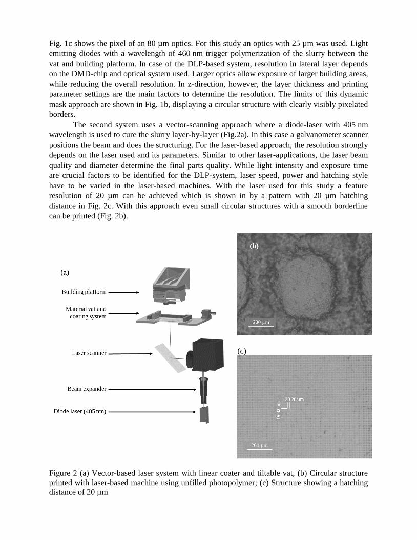
Fig. 1c shows the pixel of an 80 µm optics. For this study an optics with 25 µm was used. Light
emitting diodes with a wavelength of 460 nm trigger polymerization of the slurry between the
vat and building platform. In case of the DLP-based system, resolution in lateral layer depends
on the DMD-chip and optical system used. Larger optics allow exposure of larger building areas,
while reducing the overall resolution. In z-direction, however, the layer thickness and printing
parameter settings are the main factors to determine the resolution. The limits of this dynamic
mask approach are shown in Fig. 1b, displaying a circular structure with clearly visibly pixelated
borders.
The second system uses a vector-scanning approach where a diode-laser with 405 nm
wavelength is used to cure the slurry layer-by-layer (Fig.2a). In this case a galvanometer scanner
positions the beam and does the structuring. For the laser-based approach, the resolution strongly
depends on the laser used and its parameters. Similar to other laser-applications, the laser beam
quality and diameter determine the final parts quality. While light intensity and exposure time
are crucial factors to be identified for the DLP-system, laser speed, power and hatching style
have to be varied in the laser-based machines. With the laser used for this study a feature
resolution of 20 µm can be achieved which is shown in by a pattern with 20 µm hatching
distance in Fig. 2c. With this approach even small circular structures with a smooth borderline
can be printed (Fig. 2b).
(c)
Figure 2 (a) Vector-based laser system with linear coater and tiltable vat, (b) Circular structure
printed with laser-based machine using unfilled photopolymer; (c) Structure showing a hatching
distance of 20 µm

In both systems a doctor blade (Fig. 3) ensures a total covering of material in the vat
when the building platform moves up after each layer.9 Figure 3 shows the setup of the recoating
system used in this study. This special arrangement with two parallel doctor blades serves as
reservoir for fresh slurry or resin during the printing process and allows to form a new material
layer in both movement directions. During the movement of the coater it pushes excess material
ahead of it, filling possible holes or empty spaces in the material layer. When the doctor blade
reaches the other end of the vat the excess material is pushed back into the reservoir through the
holes in the blade. This setup allows a good mixing of the slurry and an even deposition during
the job. Furthermore, very thin coated layers of material in the vat reduce the cleaning effort,
especially for delicate and porous parts, greatly. To reduce the detaching-forces to a minimum in
the separation step, the vat is slightly tilted. This is one of the most time consuming steps, but
necessary in order to avoid delamination or even detaching
(a)
(b)
Figure 3 Recoating system developed and used for the stereolithography systems at TU Wien; (a)
View of the whole system, showing the coater, material vat and clamping frame; (b) section view
of the two parallel doctor blades
After the printing process a so-called green body is obtained which has to undergo a
thermal post-processing in order to get dense ceramic parts. At lower temperatures as an initial
step the solvent and later the whole organic content is removed. The polymeric binder
decomposes during this debinding step. For each slurry composition and part geometry several
TGA measurements are necessary to find the optimal temperature program. Unsuitable heating
rates or insufficient dwelling times either result in the destruction of the part by cracks or
incompletely debinded, grey structures caused by carbon residuals in the material. Perfect
debinding leaves only the inorganic filler material which then undergoes a sintering procedure at
up to 1600 °C, depending on the ceramic material. This sintering step usually causes an overall
shrinkage of the parts of up to 25%, which has to be considered before the printing process,
having again an influence on the final part’s accuracy.
For this study different test structures and patterns were printed in order to compare the
possible resolution of both systems. Further, the printing parameters (light intensity, exposure
time, laser beam power, hatching style and speed) were varied. Influences on the thermal
treatment process are discussed.

RESULTS AND DISCUSSION
To transfer the theoretical resolution of both systems to real parts, the exposure
parameters and machine settings have to be adjusted for each material. This, however, is far
more complicated for complex systems like filled slurries, than for unfilled resins. Glass or
ceramic fillers highly influence the refractive index of the photosensitive system which is a
crucial factor for absorbance and refraction behavior and therefor curing depth,
overpolymerization and accuracy. To investigate the influences on filled systems a glass filled
composite with monomers widely used in dental applications was used (see Table I).
Table I Composition of the composite material for DLP and laser machine
Component DLP Laser
wt%
BisGMA 40 40
TEGDMA 10 10
Photoinitiator 0,2 0,2
Light Absorber 0,05 0,01
Glass filler (Schott®) 49.75 49.79
DLP-based System
Most important for the outcome is the light dose (light intensity x exposure time), which
was determined for each composition. Maximum available intensity was 85 mW with a 25 µm
optics. For the printed test structures the light dose was set so as to get a curing depth of three
times the layer thickness (here 75 µm). This is sufficient to avoid detaching of the layers while
averting overpolymerization in z-direction. Best results were achieved at 20 mW intensity and 4s
exposure time.
Laser-based System
For printing on the laser-based system the absorber content of the slurries had to be
adapted. Higher intensities demand a higher light absorber concentrations. Having much more
tunable influence factors, the laser system requires a more detailed investigation of the curing of
a layer. Due to high intensities the exposure time to reach the necessary light dose has to be very
short, leading to high scanning speed. Best results were achieved with a scanning speed of 10000
mm/s at a laser power of 64 mW. Lower speed resulted in overpolymerization in lateral
direction. In contrast to the DLP-based systems where the time for each layer is independent of
the size of the projected image, the time needed for a laser-cured layer varies strongly with size
and shape of the printed structure. Every single line has to be scanned at least once, depending
on the hatching strategy used. Besides the decision to hatch in one (X- or Y-hatch) or both (XY-
hatch) directions, the combination of different delay settings result in a huge amount of different
hatching strategies. Fig. 4 shows two ones used in this study with the best results regarding
surface quality.
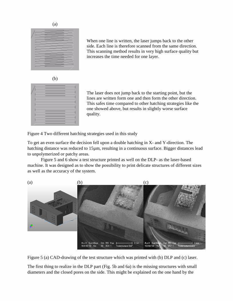
(a)
When one line is written, the laser jumps back to the other
side. Each line is therefore scanned from the same direction.
This scanning method results in very high surface quality but
increases the time needed for one layer.
(b)
The laser does not jump back to the starting point, but the
lines are written form one and then form the other direction.
This safes time compared to other hatching strategies like the
one showed above, but results in slightly worse surface
quality.
Figure 4 Two different hatching strategies used in this study
To get an even surface the decision fell upon a double hatching in X- and Y-direction. The
hatching distance was reduced to 15µm, resulting in a continuous surface. Bigger distances lead
to unpolymerized or patchy areas.
Figure 5 and 6 show a test structure printed as well on the DLP- as the laser-based
machine. It was designed as to show the possibility to print delicate structures of different sizes
as well as the accuracy of the system.
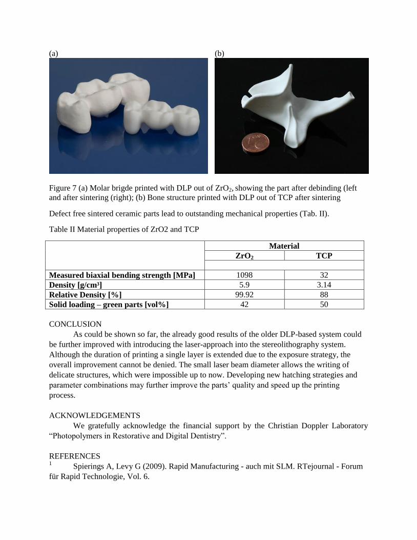
(a) (b) (c)
Figure 5 (a) CAD-drawing of the test structure which was printed with (b) DLP and (c) laser.
The first thing to realize in the DLP part (Fig. 5b and 6a) is the missing structures with small
diameters and the closed pores on the side. This might be explained on the one hand by the

resolution of the system, making it difficult to structure details with dimensions about the pixel
size (here 25 µm). On the other hand, machine settings like tilting speed of the vat and therefore
detaching force are not appropriate for this material and lead to rupture of the small pillars. The
laser-printed part (Fig. 5c and 6b), however, shows every detail of the test structure. The round
pillar structures on the top are slightly overpolymerized which can be lead back to the delay
settings of the laser-scanning system, since it could not be changed by varying the laser power or
scanning speed.
To remove unpolymerized residues from the parts, they were cleaned with Ethanol for 2
minutes. In the case of the composite used for this test structure, the solvent attacked the surface
significantly, visible in Fig. 5c. A suitable solvent has yet to be found.
(a) (b)
Figure 6 Side part of the test structure showing cavities and pillar structures of different
diameters (50 – 250 µm) printed with (a) DLP and (b) laser
With a width of 18 µm of a single laser-written line the hatching distance of 15 µm might still be
too high, although the surface seems smooth enough. Therefore, also the hatching distance has to
be further optimized in order to get an even surface.
Mechanical Properties
The high resolution in combination with proper post treatment results in parts with
excellent surface quality. This allows the fabrication of not only dense, but also smooth ceramic
parts which is essential when it comes to mechanical properties. The lesser surface damages, the
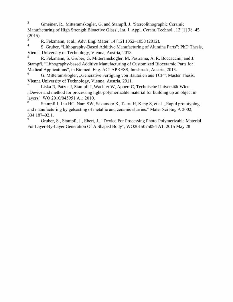
higher the bending strength values which can be achieved. Fig. 7 shows sintered ceramic parts of
ZrO2 and TCP.
(a) (b)
Figure 7 (a) Molar brigde printed with DLP out of ZrO2, showing the part after debinding (left
and after sintering (right); (b) Bone structure printed with DLP out of TCP after sintering
Defect free sintered ceramic parts lead to outstanding mechanical properties (Tab. II).
Table II Material properties of ZrO2 and TCP
Material
ZrO2 TCP
Measured biaxial bending strength [MPa] 1098
32
Density [g/cm³] 5.9 3.14
Relative Density [%] 99.92 88
Solid loading – green parts [vol%] 42 50
CONCLUSION
As could be shown so far, the already good results of the older DLP-based system could
be further improved with introducing the laser-approach into the stereolithography system.
Although the duration of printing a single layer is extended due to the exposure strategy, the
overall improvement cannot be denied. The small laser beam diameter allows the writing of
delicate structures, which were impossible up to now. Developing new hatching strategies and
parameter combinations may further improve the parts’ quality and speed up the printing
process.
ACKNOWLEDGEMENTS
We gratefully acknowledge the financial support by the Christian Doppler Laboratory
“Photopolymers in Restorative and Digital Dentistry”.
REFERENCES 1 Spierings A, Levy G (2009). Rapid Manufacturing - auch mit SLM. RTejournal - Forum
für Rapid Technologie, Vol. 6.
2 Gmeiner, R., Mitteramskogler, G. and Stampfl, J. ‘Stereolithographic Ceramic
Manufacturing of High Strength Bioactive Glass’, Int. J. Appl. Ceram. Technol., 12 [1] 38–45
(2015) 3 R. Felzmann, et al., Adv. Eng. Mater. 14 [12] 1052–1058 (2012).
4 S. Gruber, “Lithography-Based Additive Manufacturing of Alumina Parts”; PhD Thesis,
Vienna University of Technology, Vienna, Austria, 2013. 5 R. Felzmann, S. Gruber, G. Mitteramskogler, M. Pastrama, A. R. Boccaccini, and J.
Stampfl. “Lithography-based Additive Manufacturing of Customized Bioceramic Parts for
Medical Applications”, in Biomed. Eng. ACTAPRESS, Innsbruck, Austria, 2013. 6 G. Mitteramskogler, „Generative Fertigung von Bauteilen aus TCP“; Master Thesis,
Vienna University of Technology, Vienna, Austria, 2011. 7 Liska R, Patzer J, Stampfl J, Wachter W, Appert C, Technische Universität Wien.
„Device and method for processing light-polymerizable material for building up an object in
layers.” WO 2010/045951 A1; 2010. 8 Stampfl J, Liu HC, Nam SW, Sakamoto K, Tsuru H, Kang S, et al. „Rapid prototyping
and manufacturing by gelcasting of metallic and ceramic slurries.” Mater Sci Eng A 2002;
334:187–92.1. 9 Gruber, S., Stampfl, J., Ebert, J., “Device For Processing Photo-Polymerizable Material
For Layer-By-Layer Generation Of A Shaped Body”, WO2015075094 A1, 2015 May 28