Embed Size (px)
Citation preview
International Research Journal of Engineering and Technology (IRJET) e-ISSN: 2395-0056
Volume: 04 Issue: 08 | Aug -2017 www.irjet.net p-ISSN: 2395-0072
© 2017, IRJET | Impact Factor value: 5.181 | ISO 9001:2008 Certified Journal | Page 898
Comparison of Pressure Drop Characteristics of Swing Plate and Dual Plate Check Valve Using CFD
Madhvesh.L1, Panduranga B.P2, Dr. V Seshadri 3
1M. Tech. Student, Thermal Power Engineering, MIT-Mysore, Karnataka, India 2Assistant Professor, Department of Mechanical Engineering, MIT-Mysore, Karnataka, India
3Professor (Emeritus), Department of Mechanical Engineering, MIT-Mysore, Karnataka, India ---------------------------------------------------------------------***---------------------------------------------------------------------
Abstract – In the present study the pressure drop characteristics of two types of check valve namely swing plate and dual plate check valve have been analyzed using CFD under varying conditions of operations. The CFD software ANSYS FLUENT has been used. The methodology is validated by identifying proper method of discretization of flow domain and selection of suitable turbulence model. As a first step the analysis is carried out using 2D approximation the values of co-efficient of pressure (CP), co-efficient of drag (CD), permanent pressure loss co-efficient (CL) and minimum pressure (Pmin) are calculated for both types of valves at various angles of openings for a fixed Reynolds number of 105. It is observed that the dual plate check valve gives lesser pressure drop. The effect of Reynolds number at valve opening of 450 also has been studied for range of Re from 1 to 105. The flow through two valves is analyzed with 3D geometry. In the case of swing plate check valve 3 different diameters of namely 0.9D, 0.8D and 0.7D are considered. For all these cases effect of angle opening is studied at Re= 105. Further at an opening of 450 effect of Reynolds number is studied. The values of minimum pressure for each case are calculated to identify the possibilities of cavitation. It is observed that dual plate check valve is much superior in terms of pressure drop and minimum pressure characteristics. Further for swing plate check valve the optimum is observed to be at 0.8D. Key Words: Computational Fluid Dynamics, swing plate check valve, dual plate check valve, pressure loss co-efficient, Permanent Pressure loss Coefficient, drag force co-efficient, minimum Pressure, cavitation. 1. INTRODUCTION Check valves are the mechanical devices that are used to regulate the flow of the fluid in unidirectional (one direction) path and stop the reverse flow of the fluid in the other direction. They are also called as unidirectional valves, Non-Return valves.
Swing Plate Check Valve
The main purpose of using a check valve is to prevent fluid flow from travelling in the upstream direction. A swing plate check valve works accordingly by letting a hinged disc close
against a valve seat. So when the force applied on the disc caused by the pressure distribution is not large enough to overcome the weight of the disc. Swing plate check valve has the longest closing time, Because of its high inertia of the closing disc, and also due to the long distance to travel until the valve is completely closed.
Fig -1: swing plate check valve
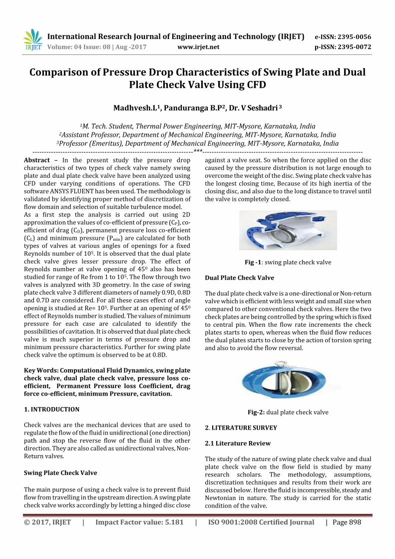
Dual Plate Check Valve The dual plate check valve is a one-directional or Non-return valve which is efficient with less weight and small size when compared to other conventional check valves. Here the two check plates are being controlled by the spring which is fixed to central pin. When the flow rate increments the check plates starts to open, whereas when the fluid flow reduces the dual plates starts to close by the action of torsion spring and also to avoid the flow reversal.
Fig-2: dual plate check valve
2. LITERATURE SURVEY 2.1 Literature Review The study of the nature of swing plate check valve and dual plate check valve on the flow field is studied by many research scholars. The methodology, assumptions, discretization techniques and results from their work are discussed below. Here the fluid is incompressible, steady and Newtonian in nature. The study is carried for the static condition of the valve.
International Research Journal of Engineering and Technology (IRJET) e-ISSN: 2395-0056
Volume: 04 Issue: 08 | Aug -2017 www.irjet.net p-ISSN: 2395-0072
© 2017, IRJET | Impact Factor value: 5.181 | ISO 9001:2008 Certified Journal | Page 899
Adarsh k m et.al [1] carried numerical simulation of flow through two types of valves namely dual plate check valve and butterfly valve and was for various opening conditions. Methodology is validated by using k-ɛ model by analyzing the developing flow through circular pipe. The value of pressure loss coefficient (cp) and drag force coefficient (cd) has been evaluated at various openings and Reynolds number. It is observed that values of pressure loss coefficient (cp) and drag force coefficient (cd) are lower in case of dual plate check valve. Martin Turesson et.al [2] investigated and compared three different RELAP5 swing check valves models to the corresponding CFD simulations. The first model is the built-in description of a swing check valve in RELAP5, while the other two are models based on either another 1D code named DRAKO or on quasi-stationary CFD simulations. All three of these models are shown to under-predict the time for closure and thus also the maximum reverse velocity. Three different valve sizes have been simulated together with four different flow transients and they all show the same behavior. EMIL BOQVIST et.al [3] in his master’s thesis has studied the static and dynamic characteristics of a typical swing check valve since this type of valve causes very high loadings when slamming due to backward flow. Performing both steady state CFD- and transient FSI(Fluid-Structure Interaction)-calculations, with the disc able to move with the flow, in ANSYS FLUENT on a swing check valve will yield daily operating pressure losses and the dynamic behavior of the closing disc. Scope of the Present Study
In our present study CFD has been utilized in order to analyze the flow of fluid through dual plate check valve and swing plate check valve.
Analysis is carried out for various disc positions (valve openings) and Reynolds number. The variation in both laminar and turbulent regime is analyzed.
The change in pressure loss co-efficient (Cp), permanent pressure loss co-efficient (CL), and co-efficient of drag (CD) with valve openings at various Reynolds numbers are being analyzed and the characteristics of the two valves are compared.
With the help of minimum pressure cavitation characteristics are compared.
3 CFD METHODOLOGY AND VALIDATION Methodology There are lots of selection criteria that we need to choose when we opt for CFD analysis, like approximating the geometrical structure, selection of proper technique for
discretization, various boundary conditions, and flow assumptions. To analyze generated results after numerical simulation. Validation of the CFD Methodology Models Theo
retical Pressure Drop (Pa)
Computed Pressure Drop (Pa)
Theoretical Value Of (Umax/Uavg)
Computed Value Of (Umax/Uavg)
Axial Velocity m/s
Laminar
5332 5331.77 2 1.995 3.99
K- Ε 1632 1628.75 1.25 1.24 2.48
K-Ω 1632 1630.33 1.25 1.2495 2.499
K-Ω-Sst 1632 1631.24 1.25 1.2499 2.4998
Table-3: Comparison of Theoretical and CFD Results for Flow through Pipe
From the above table-3 we can compare the computed results with that of the theoretical results and it is validated that the computed results are closer and from the entire three turbulence model it is evident that k-ω-sst gives better results and thus this model is further used for problems having above similar boundary conditions. 4 THREE DIMENSIONAL ANALYSIS OF FLOW THROUGH CHECK VALVES In order to match the variations with that of the practical usage we are now going to perform the fluid flow analysis of the 3D swing plate and dual plate check valve using validated CFD methodology. Since the analysis performed is 3D, the results that obtained give quantitate output. We can also analyze the practical problems that are caused during experiment conducted. We can achieve closest possible results for co-efficient of pressure (CP), co-efficient of drag (CD) which is observed in practical cases. We can also analyze the minimum pressure (Pmin) formed at various valve angle opening which can cause cavitation, if the pressure reduces below that of the vapour pressure. The present chapter gives the details about the 3D analysis made and results obtained for 3D flow domain. 4.1 Three Dimensional Analysis of Flow through Dual Plate Check Valve As a basic step computations are performed for 3D flow domain, assuming certain boundary conditions and to analyze parameters like pressure loss co-efficient, drag force co-efficient, permanent pressure loss co-efficient, minimum pressure.
International Research Journal of Engineering and Technology (IRJET) e-ISSN: 2395-0056
Volume: 04 Issue: 08 | Aug -2017 www.irjet.net p-ISSN: 2395-0072
© 2017, IRJET | Impact Factor value: 5.181 | ISO 9001:2008 Certified Journal | Page 900
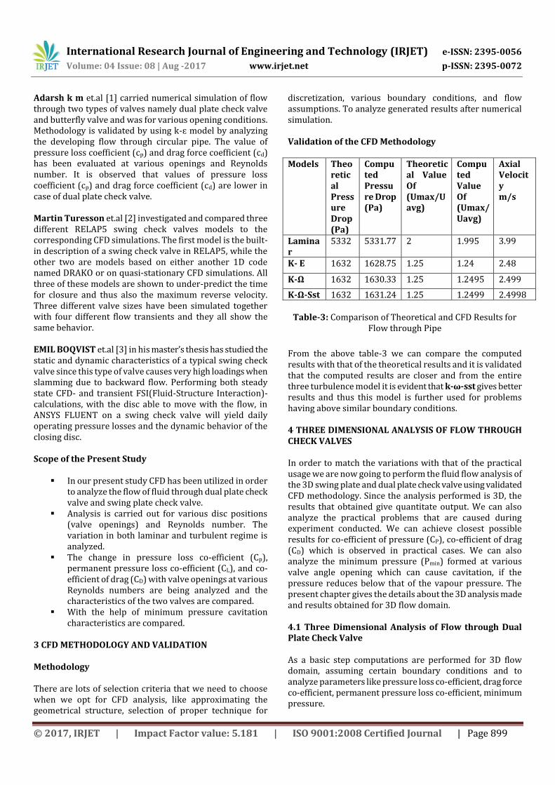
3D Flow domain of dual plate check valve The flow domain used for the analysis is shown in
fig-6. It consists of a 3D duct having a diameter of 50 mm (D). Two semi-circular valve discs is placed inside the duct it is free to rotate about the center so as to simulate the opening of the valve. In order to ensure that the flow at the valve discs is undisturbed as well as boundary conditions do not affect the computations a straight length of 5D of upstream and 10D of downstream are included as shown. Here the thickness of the valve plate is taken as 3mm. the other geometrical parameters are listed in table 4
Fig-6: Three Dimensional Isometric Flow Domain of Dual Plate Check Valve Having Symmetry
PARAMETERS DIMENSIONS
Length of the duct 0.75 m
Upstream straight length 0.25 m
Downstream straight length 0.5 m
Upstream pressure tap distance 0.15 m
Downstream pressure tap distance 0.4 m
diameter of valve discs 0.025 m
Width of the duct 0.025m
Thickness of the valve disc 0.003 m
Table-4: Geometric Parameters of the 3D Flow Domain
of Dual Plate Check Valves
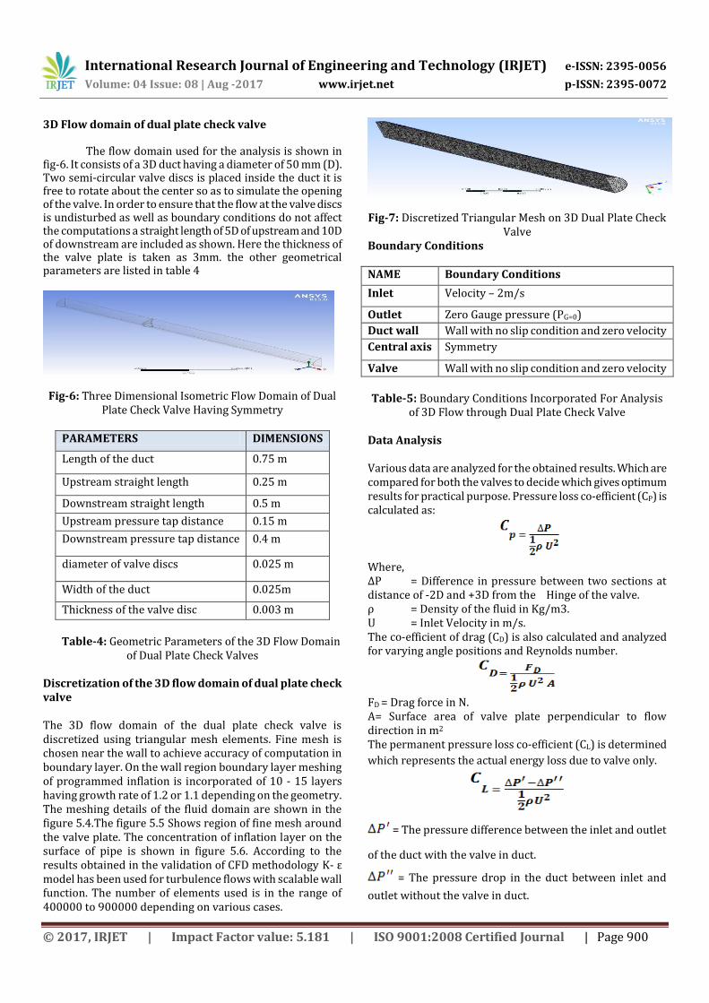
Discretization of the 3D flow domain of dual plate check valve The 3D flow domain of the dual plate check valve is discretized using triangular mesh elements. Fine mesh is chosen near the wall to achieve accuracy of computation in boundary layer. On the wall region boundary layer meshing of programmed inflation is incorporated of 10 - 15 layers having growth rate of 1.2 or 1.1 depending on the geometry. The meshing details of the fluid domain are shown in the figure 5.4.The figure 5.5 Shows region of fine mesh around the valve plate. The concentration of inflation layer on the surface of pipe is shown in figure 5.6. According to the results obtained in the validation of CFD methodology K- ε model has been used for turbulence flows with scalable wall function. The number of elements used is in the range of 400000 to 900000 depending on various cases.
Fig-7: Discretized Triangular Mesh on 3D Dual Plate Check Valve
Boundary Conditions NAME Boundary Conditions
Inlet Velocity – 2m/s
Outlet Zero Gauge pressure (PG=0)
Duct wall Wall with no slip condition and zero velocity
Central axis Symmetry
Valve Wall with no slip condition and zero velocity
Table-5: Boundary Conditions Incorporated For Analysis
of 3D Flow through Dual Plate Check Valve
Data Analysis Various data are analyzed for the obtained results. Which are compared for both the valves to decide which gives optimum results for practical purpose. Pressure loss co-efficient (CP) is calculated as:
Where, ∆P = Difference in pressure between two sections at distance of -2D and +3D from the Hinge of the valve. ρ = Density of the fluid in Kg/m3. U = Inlet Velocity in m/s. The co-efficient of drag (CD) is also calculated and analyzed for varying angle positions and Reynolds number.
FD = Drag force in N. A= Surface area of valve plate perpendicular to flow direction in m2 The permanent pressure loss co-efficient (CL) is determined
which represents the actual energy loss due to valve only.
= The pressure difference between the inlet and outlet
of the duct with the valve in duct.
= The pressure drop in the duct between inlet and
outlet without the valve in duct.
International Research Journal of Engineering and Technology (IRJET) e-ISSN: 2395-0056
Volume: 04 Issue: 08 | Aug -2017 www.irjet.net p-ISSN: 2395-0072
© 2017, IRJET | Impact Factor value: 5.181 | ISO 9001:2008 Certified Journal | Page 901
Both and are computed at same working
conditions namely Re, U, etc.
Range Of Parameters Studied Similar to the analysis of 2D cases even in 3D dual plate check valve we study the same range of parameters for further comparison. Analysis of flow through 3D dual plate check valves at nine angle openings namely 100, 200 up to 900 have been made. For those analyses Re is kept constant as 105. At Ɵ=450 the analysis has been made at various Re namely 1, 10, 100…etc. thus the range is covered.
In both laminar and Turbulent cases the value of , U, H are
kept constant namely kg/m3, U= 2m/s, D=0.05m.
Results and Discussions Ɵ ΔP
CP FD
CD CL Pmin
10 778716.6
3 389.3 753.1 7.647 387.9 -
267990
20 246977.47
123.4 236.5 2.517 122.6 -11810
30 87482.76 43.74 82.80 0.956 43.41 41000
40 30530.956
15.26 28.17 0.367 15.05 66130
50 10761.022
5.380 9.499 0.147 5.11 88140
60 4116.8568
2.058 3.233 0.046 1.83 93370
70 1624.10 0.812 1.099 0.042 0.59 96890
80 1173.15 0.586 0.748 0.033 0.32 97630
90 929.649 0.464 0.471 0 0.19 96510
Table-6: Results for 3D Analysis of Flow through Dual
Plate Check Valve for Various Valve Openings at Re=105
The above results shown in the Table 6 gives an idea that as the valve opening increases the pressure drop gradually decreases. Due to which the co-efficient of pressure also reduces. As said previously pressure drop adds to the major part of the drag force with the viscous forces added by the fluid in small quantity. The computed value of the drag force in the analysis would be slightly higher when compared to the drag force calculated theoretically. This is because the viscous force adds up in the computed results. Hence in 3D cases we can observe much low co-efficient of pressure drop, which means to say that the energy lost is minimal during large valve opening angles.
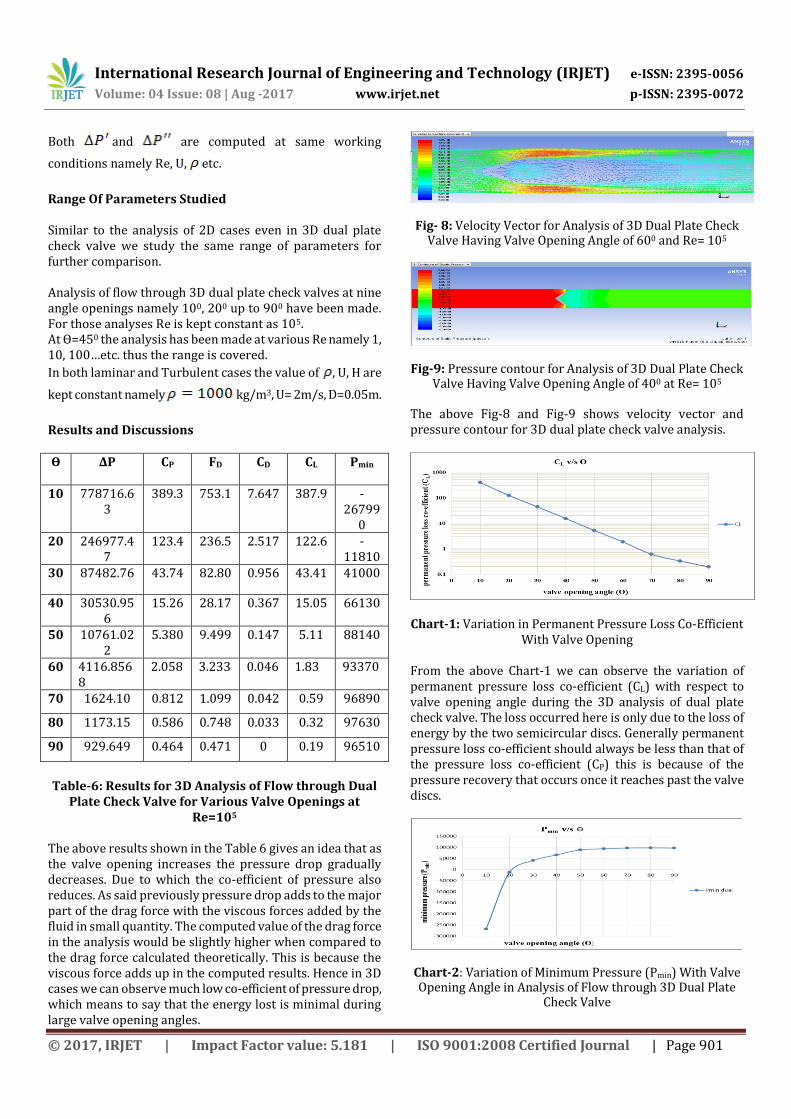
Fig- 8: Velocity Vector for Analysis of 3D Dual Plate Check Valve Having Valve Opening Angle of 600 and Re= 105
Fig-9: Pressure contour for Analysis of 3D Dual Plate Check Valve Having Valve Opening Angle of 400 at Re= 105
The above Fig-8 and Fig-9 shows velocity vector and pressure contour for 3D dual plate check valve analysis.
Chart-1: Variation in Permanent Pressure Loss Co-Efficient With Valve Opening
From the above Chart-1 we can observe the variation of permanent pressure loss co-efficient (CL) with respect to valve opening angle during the 3D analysis of dual plate check valve. The loss occurred here is only due to the loss of energy by the two semicircular discs. Generally permanent pressure loss co-efficient should always be less than that of the pressure loss co-efficient (CP) this is because of the pressure recovery that occurs once it reaches past the valve discs.
Chart-2: Variation of Minimum Pressure (Pmin) With Valve Opening Angle in Analysis of Flow through 3D Dual Plate
Check Valve
International Research Journal of Engineering and Technology (IRJET) e-ISSN: 2395-0056
Volume: 04 Issue: 08 | Aug -2017 www.irjet.net p-ISSN: 2395-0072
© 2017, IRJET | Impact Factor value: 5.181 | ISO 9001:2008 Certified Journal | Page 902
Below the valve discs lowest possible pressure is observed, which is reason for the cavitation to occur in the valve. As the valve opening increases from minimum to maximum even the value of minimum pressure reduces. In order to avoid the cavitation to occur in the valves we need to make sure that the minimum pressure does not go below the vapour pressure.in the above Chart-2 the minimum pressure is in terms of the standard absolute pressure. Effect of Reynolds Number In order to study the effect of Reynolds number on the characteristics of the valve, the valve opening angle is kept fixed to 500 and Reynolds number is varied from 1 to 100000. This variation consists of both laminar and turbulent regime.
Re CP FD CD CL
1 827.572 1116.68 17.37 330.94
10 85.583 86.780 1.350 14.77
100 14.928 18.192 0.283 13.95
1000 8.8126 11.098 0.0170 8.28
10000 5.700 5.523 0.085 5.19
100000 5.380 9.499 0.147 5.11
Table-7: 3D Analysis of Flow through Dual Plate Check
Valve by Varying Re at Valve Opening Angle Of 500
From the Table-7 it is evident that at low Reynolds number the pressure drop and pressure loss co-efficient are very high due to the contribution of the high viscous forces And also the permanent pressure loss co-efficient (CL) also decreases as the Reynolds number increases. When the flow changes from laminar to turbulent regime we can observe very low or stagnant pressure drop as well as the permanent pressure loss co-efficient because the viscous forces are nullified.
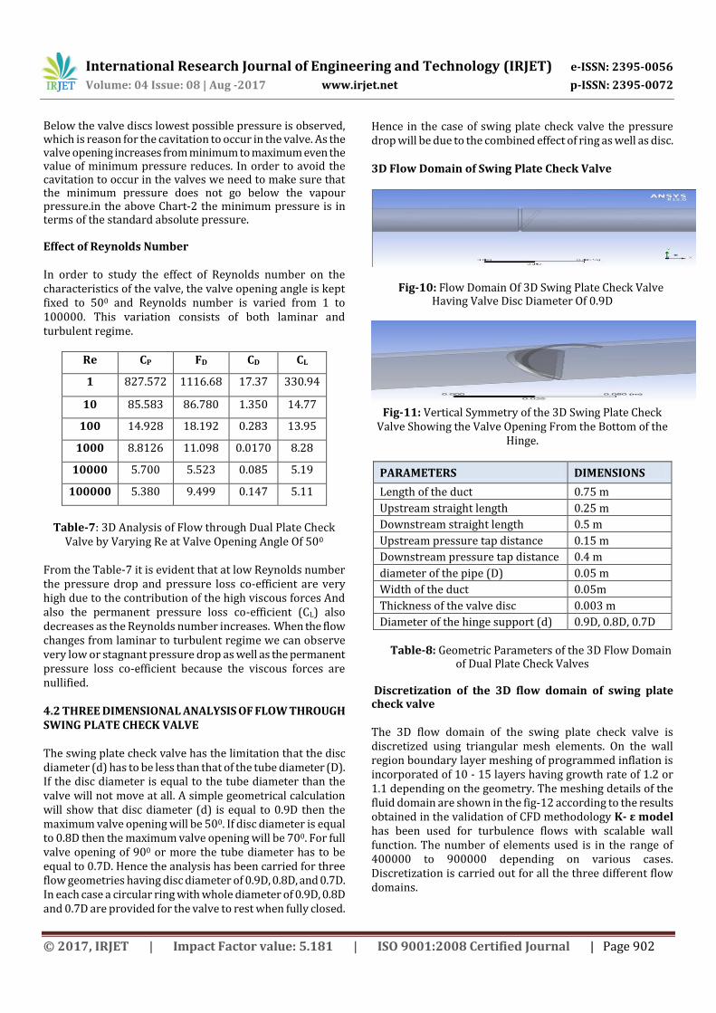
4.2 THREE DIMENSIONAL ANALYSIS OF FLOW THROUGH SWING PLATE CHECK VALVE The swing plate check valve has the limitation that the disc diameter (d) has to be less than that of the tube diameter (D). If the disc diameter is equal to the tube diameter than the valve will not move at all. A simple geometrical calculation will show that disc diameter (d) is equal to 0.9D then the maximum valve opening will be 500. If disc diameter is equal to 0.8D then the maximum valve opening will be 700. For full valve opening of 900 or more the tube diameter has to be equal to 0.7D. Hence the analysis has been carried for three flow geometries having disc diameter of 0.9D, 0.8D, and 0.7D. In each case a circular ring with whole diameter of 0.9D, 0.8D and 0.7D are provided for the valve to rest when fully closed.
Hence in the case of swing plate check valve the pressure drop will be due to the combined effect of ring as well as disc. 3D Flow Domain of Swing Plate Check Valve
Fig-10: Flow Domain Of 3D Swing Plate Check Valve Having Valve Disc Diameter Of 0.9D
Fig-11: Vertical Symmetry of the 3D Swing Plate Check
Valve Showing the Valve Opening From the Bottom of the Hinge.
PARAMETERS DIMENSIONS
Length of the duct 0.75 m
Upstream straight length 0.25 m
Downstream straight length 0.5 m
Upstream pressure tap distance 0.15 m
Downstream pressure tap distance 0.4 m
diameter of the pipe (D) 0.05 m
Width of the duct 0.05m
Thickness of the valve disc 0.003 m
Diameter of the hinge support (d) 0.9D, 0.8D, 0.7D
Table-8: Geometric Parameters of the 3D Flow Domain of Dual Plate Check Valves
Discretization of the 3D flow domain of swing plate check valve The 3D flow domain of the swing plate check valve is discretized using triangular mesh elements. On the wall region boundary layer meshing of programmed inflation is incorporated of 10 - 15 layers having growth rate of 1.2 or 1.1 depending on the geometry. The meshing details of the fluid domain are shown in the fig-12 according to the results obtained in the validation of CFD methodology K- ε model has been used for turbulence flows with scalable wall function. The number of elements used is in the range of 400000 to 900000 depending on various cases. Discretization is carried out for all the three different flow domains.
International Research Journal of Engineering and Technology (IRJET) e-ISSN: 2395-0056
Volume: 04 Issue: 08 | Aug -2017 www.irjet.net p-ISSN: 2395-0072
© 2017, IRJET | Impact Factor value: 5.181 | ISO 9001:2008 Certified Journal | Page 903
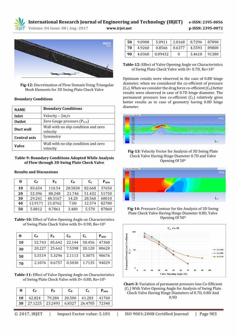
Fig-12: Discretization of Flow Domain Using Triangular Mesh Elements for 3D Swing Plate Check Valve
Boundary Conditions
NAME Boundary Conditions
Inlet Velocity – 2m/s
Outlet Zero Gauge pressure (PG=0)
Duct wall Wall with no slip condition and zero velocity
Central axis Symmetry
Valve Wall with no slip condition and zero velocity
Table-9: Boundary Conditions Adopted While Analysis
of Flow through 3D Swing Plate Check Valve
Results and Discussions
Ɵ CP FD CD CL Pmin
10 83.654 110.54 28.5830 82.668 37650
20 52.396 80.248 21.746 51.432 51750 30 29.241 48.3167 14.20 28.560 68010 40 12.9171 21.0762 7.00 12.574 82780
50 5.8812 8.7861 3.480 5.570 87860
Table-10: Effect of Valve Opening Angle on Characteristics
of Swing Plate Check Valve with D= 0.9D, Re=105
Ɵ CP FD CD CL Pmin
10 52.743 85.642 22.144 50.456 47360
30 20.227 25.642 7.5398 20.120 80620
50 5.5519 5.3296 2.1113 5.3075 90676
70 2.1076 0.6757 0.5030 1.7135 94029
Table-11: Effect of Valve Opening Angle on Characteristics
of Swing Plate Check Valve with D= 0.8D, Re=105
Ɵ CP FD CD CL Pmin
10 62.824 79.284 20.500 61.283 41760
30 27.1225 23.2493 6.8327 26.4705 72340
50 9.0908 5.0911 2.0168 8.7296 87890
70 4.9260 0.8566 0.6377 4.5593 89800
90 4.0368 0.09432 0 3.4618 91380
Table-12: Effect of Valve Opening Angle on Characteristics
of Swing Plate Check Valve with D= 0.7D, Re=105 Optimum results were observed in the case of 0.8D hinge diameter, when we considered the co-efficient of pressure (CP). When we consider the drag force co-efficient (CD) better results were observed in case of 0.7D hinge diameter. The permanent pressure loss co-efficient (CL) relatively gives better results as in case of geometry having 0.8D hinge diameter.
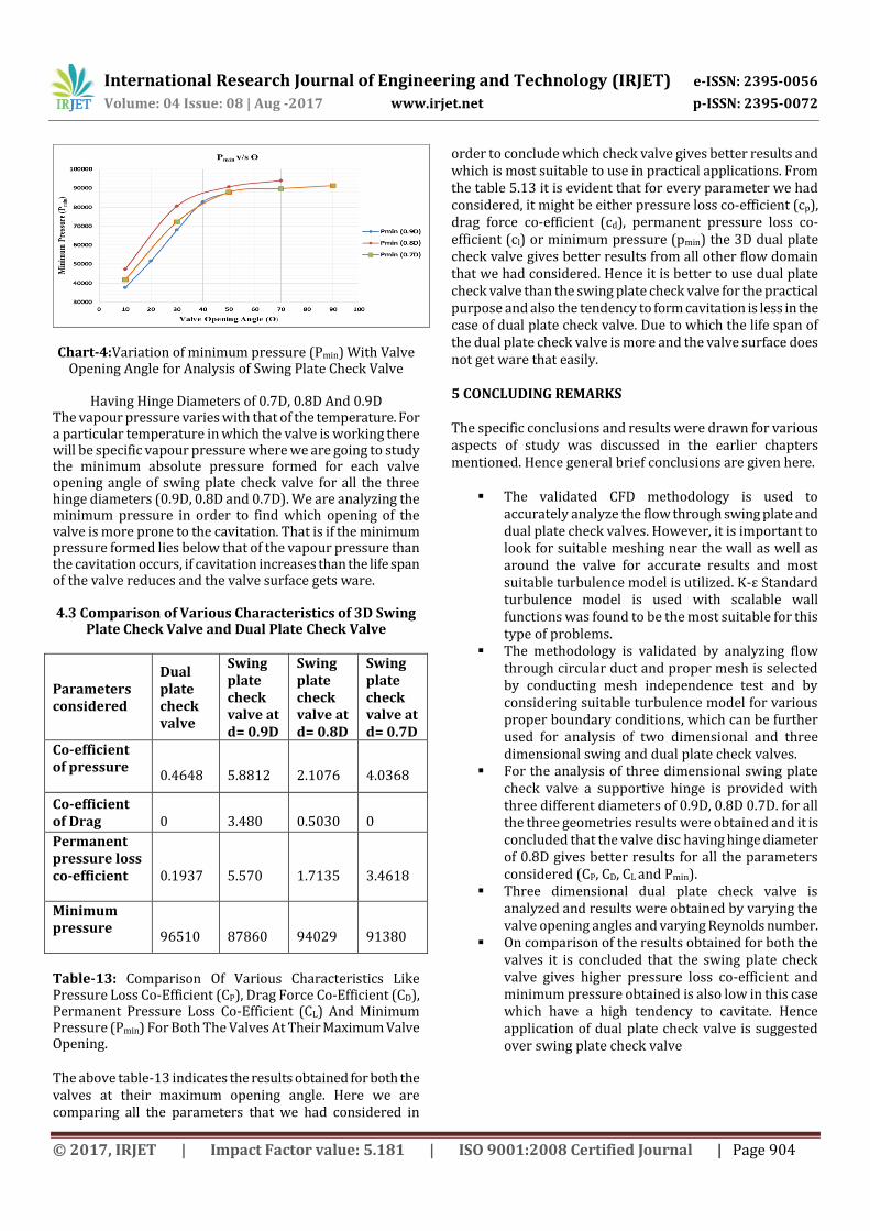
Fig-13: Velocity Vector for Analysis of 3D Swing Plate Check Valve Having Hinge Diameter 0.7D and Valve
Opening Of 500
Fig-14: Pressure Contour for the Analysis of 3D Swing Plate Check Valve Having Hinge Diameter 0.8D, Valve
Opening Of 500
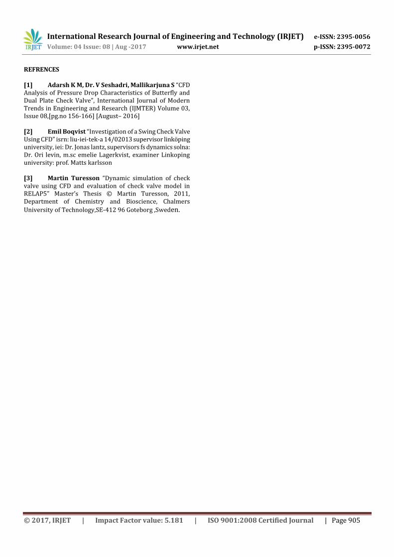
Chart-3: Variation of permanent pressure loss Co-Efficient (CL) With Valve Opening Angle for Analysis of Swing Plate
Check Valve Having Hinge Diameters of 0.7D, 0.8D And 0.9D
International Research Journal of Engineering and Technology (IRJET) e-ISSN: 2395-0056
Volume: 04 Issue: 08 | Aug -2017 www.irjet.net p-ISSN: 2395-0072
© 2017, IRJET | Impact Factor value: 5.181 | ISO 9001:2008 Certified Journal | Page 904
Chart-4:Variation of minimum pressure (Pmin) With Valve Opening Angle for Analysis of Swing Plate Check Valve
Having Hinge Diameters of 0.7D, 0.8D And 0.9D
The vapour pressure varies with that of the temperature. For a particular temperature in which the valve is working there will be specific vapour pressure where we are going to study the minimum absolute pressure formed for each valve opening angle of swing plate check valve for all the three hinge diameters (0.9D, 0.8D and 0.7D). We are analyzing the minimum pressure in order to find which opening of the valve is more prone to the cavitation. That is if the minimum pressure formed lies below that of the vapour pressure than the cavitation occurs, if cavitation increases than the life span of the valve reduces and the valve surface gets ware. 4.3 Comparison of Various Characteristics of 3D Swing
Plate Check Valve and Dual Plate Check Valve
Parameters considered
Dual plate check valve
Swing plate check valve at d= 0.9D
Swing plate check valve at d= 0.8D
Swing plate check valve at d= 0.7D
Co-efficient of pressure
0.4648
5.8812
2.1076
4.0368
Co-efficient of Drag
0
3.480
0.5030
0
Permanent pressure loss co-efficient
0.1937
5.570
1.7135
3.4618
Minimum pressure
96510
87860
94029
91380
Table-13: Comparison Of Various Characteristics Like Pressure Loss Co-Efficient (CP), Drag Force Co-Efficient (CD), Permanent Pressure Loss Co-Efficient (CL) And Minimum Pressure (Pmin) For Both The Valves At Their Maximum Valve Opening. The above table-13 indicates the results obtained for both the valves at their maximum opening angle. Here we are comparing all the parameters that we had considered in
order to conclude which check valve gives better results and which is most suitable to use in practical applications. From the table 5.13 it is evident that for every parameter we had considered, it might be either pressure loss co-efficient (cp), drag force co-efficient (cd), permanent pressure loss co-efficient (cl) or minimum pressure (pmin) the 3D dual plate check valve gives better results from all other flow domain that we had considered. Hence it is better to use dual plate check valve than the swing plate check valve for the practical purpose and also the tendency to form cavitation is less in the case of dual plate check valve. Due to which the life span of the dual plate check valve is more and the valve surface does not get ware that easily. 5 CONCLUDING REMARKS The specific conclusions and results were drawn for various aspects of study was discussed in the earlier chapters mentioned. Hence general brief conclusions are given here.
The validated CFD methodology is used to accurately analyze the flow through swing plate and dual plate check valves. However, it is important to look for suitable meshing near the wall as well as around the valve for accurate results and most suitable turbulence model is utilized. K-ε Standard turbulence model is used with scalable wall functions was found to be the most suitable for this type of problems.
The methodology is validated by analyzing flow through circular duct and proper mesh is selected by conducting mesh independence test and by considering suitable turbulence model for various proper boundary conditions, which can be further used for analysis of two dimensional and three dimensional swing and dual plate check valves.
For the analysis of three dimensional swing plate check valve a supportive hinge is provided with three different diameters of 0.9D, 0.8D 0.7D. for all the three geometries results were obtained and it is concluded that the valve disc having hinge diameter of 0.8D gives better results for all the parameters considered (CP, CD, CL and Pmin).
Three dimensional dual plate check valve is analyzed and results were obtained by varying the valve opening angles and varying Reynolds number.
On comparison of the results obtained for both the valves it is concluded that the swing plate check valve gives higher pressure loss co-efficient and minimum pressure obtained is also low in this case which have a high tendency to cavitate. Hence application of dual plate check valve is suggested over swing plate check valve
International Research Journal of Engineering and Technology (IRJET) e-ISSN: 2395-0056
Volume: 04 Issue: 08 | Aug -2017 www.irjet.net p-ISSN: 2395-0072
© 2017, IRJET | Impact Factor value: 5.181 | ISO 9001:2008 Certified Journal | Page 905
REFRENCES [1] Adarsh K M, Dr. V Seshadri, Mallikarjuna S “CFD Analysis of Pressure Drop Characteristics of Butterfly and Dual Plate Check Valve”, International Journal of Modern Trends in Engineering and Research (IJMTER) Volume 03, Issue 08,[pg.no 156-166] [August– 2016] [2] Emil Boqvist “Investigation of a Swing Check Valve Using CFD” isrn: liu-iei-tek-a 14/02013 supervisor linköping university, iei: Dr. Jonas lantz, supervisors fs dynamics solna: Dr. Ori levin, m.sc emelie Lagerkvist, examiner Linkoping university: prof. Matts karlsson [3] Martin Turesson “Dynamic simulation of check valve using CFD and evaluation of check valve model in RELAP5” Master’s Thesis © Martin Turesson, 2011, Department of Chemistry and Bioscience, Chalmers
University of Technology,SE-412 96 Goteborg ,Sweden.