Embed Size (px)
Citation preview
65THIEME
Original Article
Comparison of the Shaping Ability of Endowave and K3 Rotary Nickel-Titanium Instruments in Simulated CanalsRuchi Singla1 Vivek Kapoor1 Ruchi Vashisht1
1Department of Conservative Dentistry & Endodontics, Dr. HS Judge Institute of Dental Sciences & Hospital, Chandigarh, India
received September 26, 2018accepted October 5, 2018published onlineNovember 27, 2018
Address for correspondence Ruchi Singla, MDS, Department, of Conservative Dentistry and Endodontics, Dr. HS Judge Institute of Dental Sciences & Hospital, Chandigarh 160014, India (e-mail: [email protected]).
Objectives The aim of this study was to compare canal aberrations and transporta-tion of Endowave and K3 rotary nickel-titanium files in simulated canals with 40-degree curvature.Materials and Methods Twenty simulated canals with 40-degree curvature were divided into two groups (each of 10). In one group, canals were instrumented with Endowave and in the other group with K3. Both systems were used in crown-down manner, and canals were prepared till apical size # 25/0.06 taper. The pre- and post-in-strumentation radiographic scanned images were superimposed on each other using software movements and viewed for canal aberrations and transportation. Results are statistically analyzed using Student’s t-test.Results In the canals prepared with Endowave files, one (10%) ledge was created whereas in the canals prepared with K3 files, one (10%) apical zip and elbow, one (10%) ledge, and two (20%) perforations were created. When two groups were compared, results were statistically insignificant (p > 0.05) for the amount of resin removed from inner and outer aspect of the canal.Conclusions Endowave files revealed better results in terms of the canal aberrations compared to K3 files. The direction of transportation was generally toward the outer aspect with both files.
Abstract
Keywords ► canal aberration ► Endowave ► K3 ► nickel-titanium ► rotary ► transportation
Dent J Adv Stud 2018;6:65–70
DOI https://doi.org/ 10.1055/s-0038-1675884 ISSN 2321-1482.
©2018 Bhojia Dental College and Hospital affiliated to Himachal Pradesh University
IntroductionThe aim of root canal instrumentation is to clean and shape the root canal system. A continuously tapering funnel shape with the smallest diameter at the endpoint and the largest at the orifice has seemed to be the most appropriate canal shape for filling with gutta percha and sealer. Over the years, many techniques, instruments, and devices have been described, but few appear capable of producing consistently the appropriate conical form demanded by modern obtura-tion techniques. This problem is particularly important in narrow curved canals.
Problems with breakage, procedural errors such as ledges, zips, canal transportation, and inflexibility of stainless-steel
instruments led to the development of newer materials such as nickel-titanium (NiTi) instruments. Studies have shown that instrumentation with NiTi files is faster, more centered in canal lumen,1 maintained better canal original anatomy,1,2 and can effectively produce a well-tapered root canal form sufficient for obturation, with minimal risk of transporta-tion of the original canal3–5 as compared with stainless steel instrumentation. New systems also incorporate instruments with a taper greater than the ISO standard 0.02 design.3,6 Besides variation in taper, NiTi rotary instruments are char-acterized by different cross sections and blade designs.7,8
The aim of this study was to compare the canal aberra-tions and transportation with two rotary NiTi files Endowave and K3 in simulated canals with 40-degree curvature.
66 Shaping Ability of Endowave vs. K3 Singla et al.
Dental Journal of Advance Studies Vol. 6 No. 2-3/2018
Materials and MethodsInstrumentsEndowave has alternative contact points (ACPs) along the shank of the instrument that keeps the file centered in the canal and reduces torque requirement of the file. This rotary file system has been subjected to electropolishing. Electropo-lishing increases cutting efficiency of files and removes many of the imperfections in NiTi that can lead to unexplained separation.9
The K3 rotary file system was introduced in 2002. These files are designed with a wide radial land, which is meant to make the instrument more resistant to torsional and rotary stresses. It also features “radial land relief” that aids in pro-tecting the file from “over engagement” in the canal; thus, less instrument separation or distortion should occur. This file features a variable core diameter designed to increase flexibility, and it has a safe-ended tip to decrease the incidence of ledging, perforations, and zipping.10 This system has been evaluated in various studies4,7,11 and reported to be suitable for preparing curved root canals.
Preparation of Simulated CanalsTwenty simulated resin root canal blocks (Endoblock, Maillefer), 30 mm long, with the canal orifice 16 mm from the apex were taken. All canals had a mean curvature of 40 degrees. The curvature started 10 mm from the canal orifice. These were divided into two groups (each of 10): group I canals prepared with Endowave files and group II canals pre-pared with K3 files.
Simulated canals were prepared with Endowave and K3 file using 128:1 reduction gear handpiece (Anthogyr, Endodontic Ni-Ti Contra Angles, Sallanches, France) powered by a micro-motor. During preparation, each resin block was covered with black adhesive tape, masking the entire canal. This ensured that the process was performed with purely tactile sensation.
The standard protocol for canal preparation was followed. To check the patency of the canal before the root prepara-tion, ISO 10 size K-file was introduced into the simulated canal to working length. Copious irrigation with water was performed before preparation and after the use of every instrument using disposable syringes and 27-gauge irrigating tips. Approximately 20 mL of water was used per canal. Prior to use, each file was coated with glycerine to act as lubricant. Files were wiped regularly on a sponge to remove resin debris.
Canals were prepared with Endowave file using crown-down method as follows:
• Endowave size # 25/0.06 taper was used to prepare 6 mm of each canal in gentle in and out (pecking) motion. Each file was rotated freely in canal for 10 seconds, and it was removed and inspected.
• Endowave size # 25/0.04 taper was used to prepare two-thirds of the canal length.
• Endowave sizes # 25/0.02, 25/0.04 taper, and 25/0.06 tapers were used to prepare apical part of the canal.
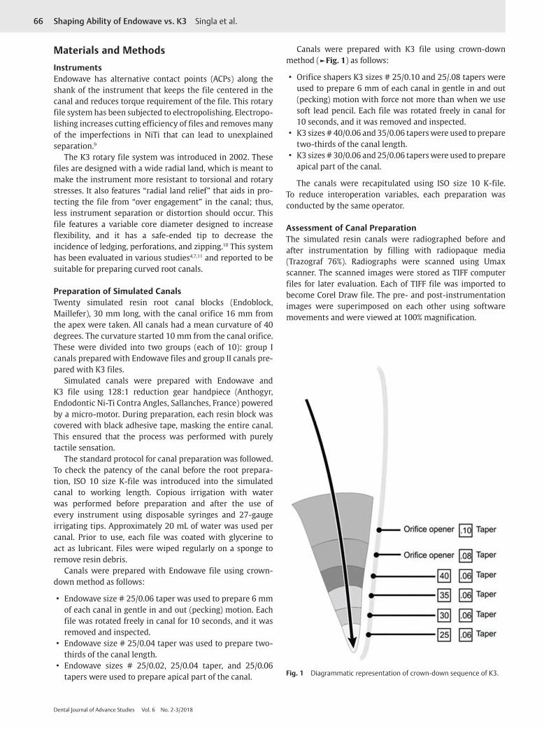
Canals were prepared with K3 file using crown-down method (►Fig. 1) as follows:
• Orifice shapers K3 sizes # 25/0.10 and 25/.08 tapers were used to prepare 6 mm of each canal in gentle in and out (pecking) motion with force not more than when we use soft lead pencil. Each file was rotated freely in canal for 10 seconds, and it was removed and inspected.
• K3 sizes # 40/0.06 and 35/0.06 tapers were used to prepare two-thirds of the canal length.
• K3 sizes # 30/0.06 and 25/0.06 tapers were used to prepare apical part of the canal.
The canals were recapitulated using ISO size 10 K-file. To reduce interoperation variables, each preparation was conducted by the same operator.
Assessment of Canal PreparationThe simulated resin canals were radiographed before and after instrumentation by filling with radiopaque media (Trazograf 76%). Radiographs were scanned using Umax scanner. The scanned images were stored as TIFF computer files for later evaluation. Each of TIFF file was imported to become Corel Draw file. The pre- and post-instrumentation images were superimposed on each other using software movements and were viewed at 100% magnification.
Fig. 1 Diagrammatic representation of crown-down sequence of K3.
67Shaping Ability of Endowave vs. K3 Singla et al.
Dental Journal of Advance Studies Vol. 6 No. 2-3/2018
An assessment was made of the presence of several types of canal aberrations (►Fig. 2).
• Apical zip, i.e., an irregular widened area created by the master apical file near the end point of the preparation.
• Elbow occurred concurrently with an apical zip and formed a narrower region more coronally.
• Ledges were present when an irregular area of resin was removed from the outer aspects of the curved portion of the canal.
• Perforations occurred as a separate and distinct false canal toward the endpoint along the outer aspect of the curve not confluent with the original canal.
• Danger zones were defined as the area coronal to be elbow where excess resin was removed from the inner aspect of the curve.
• Smooth belly was over instrumentation on the outer wall of curvature in apical part.12
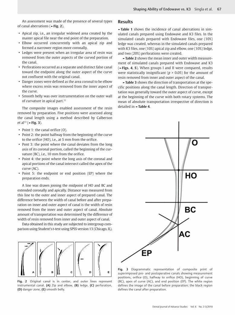
The composite images enabled assessment of the resin removed by preparation. Five positions were assessed along the canal length using a method described by Calberson et al13 (►Fig. 3).
• Point 1: the canal orifice (O). • Point 2: the point halfway from the beginning of the curve
to the orifice (HO), i.e., at 5 mm from the orifice. • Pont 3: the point where the canal deviates from the long
axis of its coronal portion, called the beginning of the cur-vature (BC), i.e., 10 mm from the orifice.
• Point 4: the point where the long axis of the coronal and apical portions of the canal intersect called the apex of the curve (AC).
• Point 5: the endpoint or end position (EP) where the preparation ends.
A line was drawn joining the midpoint of HO and BC and extended coronally and apically. Distance was measured from this line to the outer and inner aspect of prepared canal. The difference between the width of canal before and after prepa-ration on inner and outer aspect of canal is the width of resin removed from the inner and outer aspect of canal. Absolute amount of transportation was determined by the difference of width of resin removed from inner and outer aspect of canal.
Data obtained in this study are subjected to intergroup com-parison using Student’s t-test using SPSS version 13 (Chicago, IL).
Results►Table 1 shows the incidence of canal aberrations in sim-ulated canals prepared using Endowave and K3 files. In the simulated canals prepared with Endowave files, one (10%) ledge was created, whereas in the simulated canals prepared with K3 files, one (10%) apical zip and elbow, one (10%) ledge, and two (20%) perforations were created.
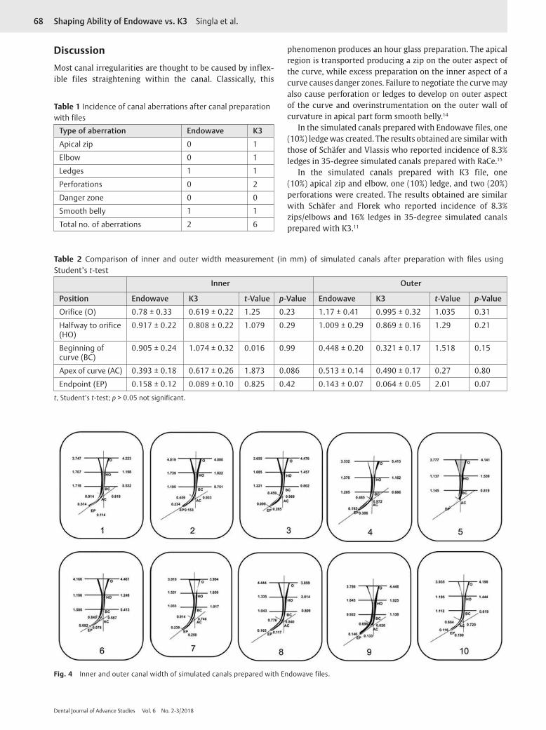
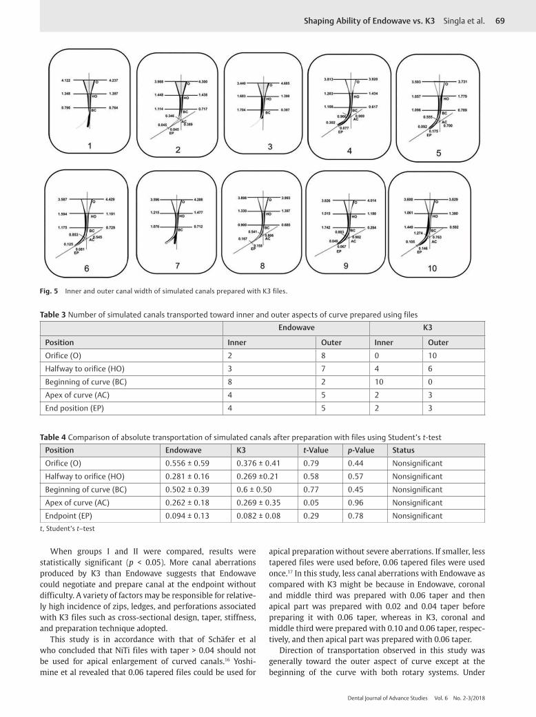
►Table 2 shows the mean inner and outer width measure-ment of simulated canals prepared with Endowave and K3 (►Figs. 4, 5). When groups I and II were compared, results were statistically insignificant (p > 0.05) for the amount of resin removed from inner and outer aspect of the canal.
►Table 3 shows the direction of transportation at the spe-cific positions along the canal length. Direction of transpor-tation was generally toward the outer aspect of curve, except at the beginning of the curve with both rotary systems. The mean of absolute transportation irrespective of direction is detailed in ►Table 4.
Fig. 2 Original canal is in center, and outer lines represent instrumental canal. (A) Zip and elbow, (B) ledge, (C) perforation, (D) danger zone, (E) smooth belly.
Fig. 3 Diagrammatic representation of composite print of superimposed pre- and postoperative canals showing measurement positions, orifice (O), halfway to orifice (HO), beginning of curve (BC), apex of curve (AC), and end position (EP). The white region defines the image of the canal before preparation; the black region defines the canal after preparation.
68 Shaping Ability of Endowave vs. K3 Singla et al.
Dental Journal of Advance Studies Vol. 6 No. 2-3/2018
DiscussionMost canal irregularities are thought to be caused by inflex-ible files straightening within the canal. Classically, this
phenomenon produces an hour glass preparation. The apical region is transported producing a zip on the outer aspect of the curve, while excess preparation on the inner aspect of a curve causes danger zones. Failure to negotiate the curve may also cause perforation or ledges to develop on outer aspect of the curve and overinstrumentation on the outer wall of curvature in apical part form smooth belly.14
In the simulated canals prepared with Endowave files, one (10%) ledge was created. The results obtained are similar with those of Schäfer and Vlassis who reported incidence of 8.3% ledges in 35-degree simulated canals prepared with RaCe.15
In the simulated canals prepared with K3 file, one (10%) apical zip and elbow, one (10%) ledge, and two (20%) perforations were created. The results obtained are similar with Schäfer and Florek who reported incidence of 8.3% zips/elbows and 16% ledges in 35-degree simulated canals prepared with K3.11
Table 1 Incidence of canal aberrations after canal preparation with files
Type of aberration Endowave K3
Apical zip 0 1
Elbow 0 1
Ledges 1 1
Perforations 0 2
Danger zone 0 0
Smooth belly 1 1
Total no. of aberrations 2 6
Table 2 Comparison of inner and outer width measurement (in mm) of simulated canals after preparation with files using Student’s t-test
Inner Outer
Position Endowave K3 t-Value p-Value Endowave K3 t-Value p-Value
Orifice (O) 0.78 ± 0.33 0.619 ± 0.22 1.25 0.23 1.17 ± 0.41 0.995 ± 0.32 1.035 0.31
Halfway to orifice (HO)
0.917 ± 0.22 0.808 ± 0.22 1.079 0.29 1.009 ± 0.29 0.869 ± 0.16 1.29 0.21
Beginning of curve (BC)
0.905 ± 0.24 1.074 ± 0.32 0.016 0.99 0.448 ± 0.20 0.321 ± 0.17 1.518 0.15
Apex of curve (AC) 0.393 ± 0.18 0.617 ± 0.26 1.873 0.086 0.513 ± 0.14 0.490 ± 0.17 0.27 0.80
Endpoint (EP) 0.158 ± 0.12 0.089 ± 0.10 0.825 0.42 0.143 ± 0.07 0.064 ± 0.05 2.01 0.07
t, Student’s t-test; p > 0.05 not significant.
Fig. 4 Inner and outer canal width of simulated canals prepared with Endowave files.
69Shaping Ability of Endowave vs. K3 Singla et al.
Dental Journal of Advance Studies Vol. 6 No. 2-3/2018
When groups I and II were compared, results were statistically significant (p < 0.05). More canal aberrations produced by K3 than Endowave suggests that Endowave could negotiate and prepare canal at the endpoint without difficulty. A variety of factors may be responsible for relative-ly high incidence of zips, ledges, and perforations associated with K3 files such as cross-sectional design, taper, stiffness, and preparation technique adopted.
This study is in accordance with that of Schäfer et al who concluded that NiTi files with taper > 0.04 should not be used for apical enlargement of curved canals.16 Yoshi-mine et al revealed that 0.06 tapered files could be used for
apical preparation without severe aberrations. If smaller, less tapered files were used before, 0.06 tapered files were used once.17 In this study, less canal aberrations with Endowave as compared with K3 might be because in Endowave, coronal and middle third was prepared with 0.06 taper and then apical part was prepared with 0.02 and 0.04 taper before preparing it with 0.06 taper, whereas in K3, coronal and middle third were prepared with 0.10 and 0.06 taper, respec-tively, and then apical part was prepared with 0.06 taper.
Direction of transportation observed in this study was generally toward the outer aspect of curve except at the beginning of the curve with both rotary systems. Under
Fig. 5 Inner and outer canal width of simulated canals prepared with K3 files.
Table 3 Number of simulated canals transported toward inner and outer aspects of curve prepared using files
Endowave K3
Position Inner Outer Inner Outer
Orifice (O) 2 8 0 10
Halfway to orifice (HO) 3 7 4 6
Beginning of curve (BC) 8 2 10 0
Apex of curve (AC) 4 5 2 3
End position (EP) 4 5 2 3
Table 4 Comparison of absolute transportation of simulated canals after preparation with files using Student’s t-test
Position Endowave K3 t-Value p-Value Status
Orifice (O) 0.556 ± 0.59 0.376 ± 0.41 0.79 0.44 Nonsignificant
Halfway to orifice (HO) 0.281 ± 0.16 0.269 ±0.21 0.58 0.57 Nonsignificant
Beginning of curve (BC) 0.502 ± 0.39 0.6 ± 0.50 0.77 0.45 Nonsignificant
Apex of curve (AC) 0.262 ± 0.18 0.269 ± 0.35 0.05 0.96 Nonsignificant
Endpoint (EP) 0.094 ± 0.13 0.082 ± 0.08 0.29 0.78 Nonsignificantt, Student’s t–test
70 Shaping Ability of Endowave vs. K3 Singla et al.
Dental Journal of Advance Studies Vol. 6 No. 2-3/2018
similar conditions, other studies have confirmed this trend with NiTi instruments, for example, Profile 0.04 Taper Series 29,18 NT engine/McXim instruments,19 Mity Roto 360-degree and Naviflex instruments,20 and Quantec Series 2000 instru-ments.21 Transportation toward the outer wall may reflect the tip design and tendency of the instruments to straight-en within the confines of the canal. This appears to be more evident in canals prepared with instruments of greater taper, which are stiffer. In contrast, in preparation of simulated canals using stainless steel hand files, transportation occurs toward the outer aspect of the curve at the endpoint and toward the inner at and around the curve. This is thought to be due to rigid nature of these instruments.22 Thus the results of this and previous studies imply that the removal of excess material from along the inner aspect of canal curve, i.e., the danger zone is not a problem with NiTi rotary instruments.
The magnitude of absolute transportation with both files was small and may be of little significance. When groups were compared, results were statistically insignificant (p < 0.05) for the amount of absolute transportation.
A major drawback of using rotary instruments in res-in blocks is the heat generated, which may soften the resin material23 and lead to binding of cutting blades and separa-tion of the instruments.6 Hence, clinical correlation in the teeth must be done with caution.
Conclusions • Endowave rotary files revealed better results in terms of
the canal aberrations as compared with K3 rotary files. • The direction of transportation was generally toward the
outer aspect with both files; however, the magnitude of transportation was small.
Conflict of InterestNone declared.
References
1 Bishop K, Dummer PMH. A comparison of stainless steel Flexofiles and nickel-titanium NiTi flex files during the shaping of simulated canals. Int Endod J 1997;30(1):25–34
2 Schäfer E. Shaping ability of Hero 642 rotary nickel-titanium instruments and stainless steel hand K-Flexofiles in simulated curved root canals. Oral Surg Oral Med Oral Pathol Oral Radiol Endod 2001;92(2):215–220
3 Thompson SA, Dummer PMH. Shaping ability of ProFile.04 Taper Series 29 rotary nickel-titanium instruments in simulat-ed root canals. Part 1. Int Endod J 1997;30(1):1–7
4 Hülsmann M, Schade M, Schäfers F. A comparative study of root canal preparation with Hero 642 and Quantec SC rotary Ni-Ti instruments. Int Endod J 2001;34(7):538–546
5 Schäfer E, Schlingemann R. Efficiency of rotary nickel-tita-nium K3 instruments compared with stainless steel hand
K-Flexofile. Part 2. Cleaning effectiveness and shaping ability in severely curved root canals of extracted teeth. Int Endod J 2003;36(3):208–217
6 Thompson SA, Dummer PMH. Shaping ability of Hero 642 rotary nickel-titanium instruments in simulated root canals: Part 1. Int Endod J 2000;33(3):248–254
7 Ankrum MT, Hartwell GR, Truitt JE. K3 Endo, ProTaper, and ProFile systems: breakage and distortion in severely curved roots of molars. J Endod 2004;30(4):234–237
8 Merrett SJ, Bryant ST, Dummer PMH. Comparison of the shap-ing ability of RaCe and FlexMaster rotary nickel-titanium sys-tems in simulated canals. J Endod 2006;32(10):960–962
9 Mohan VS. Endodontic journey. riding on the success of Endo-wave … a blueprint to success. Famdent Practical Dentistry Handbook 2006;6:28–32
10 Mounce RE. The K3 rotary nickel-titanium file system. Dent Clin North Am 2004;48(1):137–157
11 Schäfer E, Florek H. Efficiency of rotary nickel-titanium K3 instruments compared with stainless steel hand K-Flexofile. Part 1. Shaping ability in simulated curved canals. Int Endod J 2003;36(3):199–207
12 Himel VT, Ahmed KM, Wood DM, Alhadainy HA. An evalua-tion of nitinol and stainless steel files used by dental students during a laboratory proficiency exam. Oral Surg Oral Med Oral Pathol Oral Radiol Endod 1995;79(2):232–237
13 Calberson FLG, Deroose CAJG, Hommez GMG, Raes H, De Moor RJ. Shaping ability of GTTM rotary files in simulated resin root canals. Int Endod J 2002;35(7):607–614
14 Guilford WL, Lemons JE, Eleazer PD. A comparison of torque required to fracture rotary files with tips bound in simulated curved canal. J Endod 2005;31(6):468–470
15 Schäfer E, Vlassis M. Comparative investigation of two rota-ry nickel-titanium instruments: ProTaper versus RaCe. Part 1. Shaping ability in simulated curved canals. Int Endod J 2004;37(4):229–238
16 Schäfer E, Dzepina A, Danesh G. Bending properties of rotary nickel-titanium instruments. Oral Surg Oral Med Oral Pathol Oral Radiol Endod 2003;96(6):757–763
17 Yoshimine Y, Ono M, Akamine A. The shaping effects of three nickel-titanium rotary instruments in simulated S-shaped canals. J Endod 2005;31(5):373–375
18 Thompson SA, Dummer PMH. Shaping ability of ProFile.04 Taper Series 29 rotary nickel-titanium instruments in simulat-ed root canals. Part 2. Int Endod J 1997;30(1):8–15
19 Thompson SA, Dummer PMH. Shaping ability of NT engine and McXim rotary nickel-titanium instruments in simulated root canals. Part 2. Int Endod J 1997;30(4):270–278
20 Thompson SA, Dummer PMH. Shaping ability of Mity Roto 360° and Naviflex rotary nickel-titanium instruments in sim-ulated root canals. Part 2. J Endod 1998;24(2):135–142
21 Thompson SA, Dummer PMH. Shaping ability of Quantec Series 2000 rotary nickel-titanium instruments in simulated root canals: part 2. Int Endod J 1998;31(4):268–274
22 al-Omari MAO, Dummer PMH, Newcombe RG, Doller R. Com-parison of six files to prepare simulated root canals. 2. Int Endod J 1992;25(2):67–81
23 Kum KY, Spängberg L, Cha BY, et al. Shaping ability of three ProFile rotary instrumentation techniques in simulated resin root canals. J Endod 2000;26(12):719–723