Embed Size (px)
Citation preview
ORIGINAL ARTICLE
Received July 24, 2021. In revised form September 13, 2021. Accepted September 20, 2021. Available online September 21, 2021 https://doi.org/10.1590/1679-78256670
Latin American Journal of Solids and Structures. ISSN 1679-7825. Copyright © 2021. This is an Open Access article distributed under the terms of the Creative Commons Attribution License, which permits unrestricted use, distribution, and reproduction in any medium, provided the original work is properly cited.
Latin American Journal of Solids and Structures, 2021, 18(7), e402 1/16
Comparison of two FORM methodologies for reinforced concrete beams under flexure
Maílson Scherera* , Eduardo Pagnussat Titelloa , Inácio Benvegnu Morscha , Mauro de Vasconcellos Realb , Américo Campos Filhoa
a Departamento de Engenharia Civil, Escola de Engenharia, Universidade Federal do Rio Grande do Sul, Av. Osvaldo Aranha, 99 – 3º andar, 90035-190, Porto Alegre, RS, Brasil. E-mail: [email protected], [email protected], [email protected], [email protected] b Escola de Engenharia, Universidade Federal do Rio Grande, Av. Itália, km 8, 96203-900, Rio Grande, RS, Brasil. E-mail: [email protected]
* Corresponding author
https://doi.org/10.1590/1679-78256670
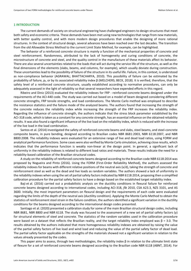
Abstract The response of a reinforced concrete structure is influenced by the variability of design parameters such as materials strengths, geometry, and load intensity. One of the most rational ways to assess the safety level of a reinforced concrete structure is to employ a probabilistic approach. This paper aims to compare the reliability indexes for a set of reinforced concrete beams according to two different methodologies, based on the association of First Order Reliability Method (FORM) with the ANSYS software. In the first methodology, the reliability indexes were assessed through the direct coupling of the FORM to the Finite Element model. In the second methodology, a response surface was employed to fit a flexural resistance function, based on the FE results, being the reliability indexes assessed by an external FORM algorithm. The results showed that both methodologies led to equivalent reliability indexes and that the safety level of the beams, which were designed according to the Brazilian code NBR 6118:2014, is mainly influenced by the load combination, presenting unsatisfactory values when the live load increases.
Keywords structural reliability; reinforced concrete beam; Finite Element Method; FORM; Response Surface Method
Graphical Abstract
Comparison of two FORM methodologies for reinforced concrete beams under flexure Maílson Scherer et al.
Latin American Journal of Solids and Structures, 2021, 18(7), e402 2/16
1 INTRODUCTION
The current demands of society on structural engineering have challenged engineers to design structures that meet both safety and economic criteria. These demands have been met using new technologies that range from new materials, with better quality control, and with more modern design procedures that enable the designing of more rational structures. In the context of structural design, several advances have been reached over the last decades. The transition from the old Allowable Stress Method to the current Limit State Method, for example, can be highlighted.
The behavior of a reinforced concrete structure is mainly a function of the mechanical properties of concrete and steel reinforcement. Randomness, attributed to the lack of homogeneity and curing conditions of concrete, the microstructure of concrete and steel, and the quality control in the manufacture of these materials affect its behavior. There are also several uncertainties related to the loads that will act during the service life of the structure, as well as the final dimensions of the elements (slabs, beams, and columns, for example), which usually deviate during construction. These uncertainties lead to the possibility of failure of the structure in its useful life. Failure, in this context, is understood as non-compliance behavior (AGRAWAL; BHATTACHARYA, 2010). This possibility of failure can be estimated by the probability of failure, pf, or by its associated reliability index β (MELCHERS; BECK, 2018). It is verified, therefore, that the safety level of a reinforced concrete structure, usually established according to normative procedures, can only be adequately assessed in the light of reliability so that several researchers have expended efforts in this regard.
Ribeiro and Diniz (2013) evaluated the reliability indexes for FRP - reinforced concrete beams designed under the requirements of the ACI-440 code. The study was carried out based on a model of beam designed considering different concrete strengths, FRP tensile strengths, and load combinations. The Monte Carlo method was employed to describe the resistance statistics and the failure mode of the analyzed beams. The authors found that increasing the strength of the concrete reduces the reliability index while increasing the strength of the FRP increases the reliability index. Regarding the influence of concrete strength, the authors indicate that the stress block parameter established by the ACI-318 code, which is taken as a constant for any concrete strength, has an essential influence on the obtained reliability results. It was also found a significant influence of the live load on the reliability index, which is reduced with the increase of the live load in the load combination.
Santos et al. (2014) investigated the safety of reinforced concrete beams and slabs, steel beams, and steel-concrete composite beams, in pure bending, designed according to Brazilian codes NBR 8681:2003, NBR 6118:2007, and NBR 8800:2008. The reliability indexes were evaluated for an extensive range of live and dead load ratios, using FORM and analytical performance functions. Some cases were also verified by Monte Carlo simulation, achieving close results, which indicates that the performance function is weakly non-linear at the design point. In general, a significant lack of uniformity in the reliability indexes is related to different load ratios and materials. These results indicate the need for a reliability-based calibration of the Brazilian structural codes.
A study on the reliability of reinforced concrete beams designed according to the Brazilian code NBR 6118:2014 was proposed by Nogueira and Pinto (2016). Using the FORM (First-Order Reliability Method), the authors assessed the reliability indexes for beams with different relative positions of the neutral axis (x/d), taking the strength of concrete and reinforcement steel as well as the dead and live loads as random variables. The authors showed a lack of uniformity in the reliability indexes when using the set of partial safety factors indicated by NBR 6118:2014, proposing then a simplified calibration procedure for the partial safety factors to have a design based on the established target reliability index.
Baji et al. (2016) carried out a probabilistic analysis on the ductility conditions in flexural failure for reinforced concrete beams designed according to international codes, including ACI-318, fib 2010, CSA A23.3, NZS 3101, and AS 3600. Initially, the most important parameters on flexural design and the requirements of each code were evaluated regarding the limits of the depth of the neutral axis (ductility condition). Applying the Monte Carlo Method to obtain the statistics of reinforcement steel strain in the failure condition, the authors identified a significant variation in the ductility conditions for the beams designed according to the international design codes presented.
Santiago et al. (2020) presented a calibration study for some of the main Brazilian structural design codes, including NBR 8681, NBR 8800 and NBR 6118. The study was focused to the assessment of a new set of partial safety factors (γ) for structural elements of steel and concrete. The statistics of the random variables used in the calibration procedure were based on a dataset that reflects the Brazilian reality, and the target reliability index employed was β = 3.0. The results obtained by the authors indicated that more homogeneous reliability indexes are obtained by raising the value of the partial safety factors of live load and wind load and reducing the value of the partial safety factor of dead load. The partial safety factor applicable on the strengths of the materials showed not a significant variation in relation to the values already presented by the codes.
This paper aims to assess, through two methodologies, the reliability index β in relation to the ultimate limit state of flexure for a set of reinforced concrete beams designed according to the Brazilian code NBR 6118 (ABNT, 2014). For
Comparison of two FORM methodologies for reinforced concrete beams under flexure Maílson Scherer et al.
Latin American Journal of Solids and Structures, 2021, 18(7), e402 3/16
such, the Finite Element Method and a customized mechanical model for concrete are associated with subroutines of reliability based on FORM. The first methodology proposes the solution by “direct coupling” of the Finite Element model with the reliability algorithm, while the second methodology proposes a solution using the Response Surface Method, which uses some numerical results (FEM) to fit a polynomial function that represents the flexural resistance of the analyzed beams. In this second methodology, the reliability analysis is performed using external subroutines, which are independent to the Finite Element model. In addition to comparisons of results assessed by the two proposed methodologies, a parametric study was carried out to verify the variation in the reliability index face to the variation in some of the main design variables, comparing the obtained reliability indexes with the target reliability index proposed by fib Model Code 2010 (Fédération Internationale du Betón, 2013).
2 DESIGN OF REINFORCED CONCRETE BEAM UNDER FLEXURE
In the context of reinforced concrete beams design, the flexural design is the determination of the amount of longitudinal reinforcement that ensures, concerning the ultimate limit state of flexure, the compliance with the inequality MRd ≥ MSd, where MRd and MSd are the flexural resistance and the flexural load, in design values, obtained by applying partial safety factors (γ). As prescribed by NBR 6118, MSd is obtained by combining loads that have a significant probability of acting simultaneously. For the most common design cases is employed the so-called normal load combination, written as in equation (1).
γ γ ψ1 0( )Sd g gk q q k j qjkM M M M (1)
Where Mgk is the characteristic value of the dead load; Mq1k is the characteristic value of the main live load; Mqjk is the characteristic value of the secondary live load. In the current format of NBR 6118, partial safety factors assume the values γg = 1.4 and γq = 1.4. The reduction factor ψ0j is taken as 0.5 for buildings loads and 0.6 for wind load. On the resistance side, MRd is obtained considering the application of partial safety factors on the characteristic strengths of concrete and reinforcement steel, as equation (2).
γ γ
ck ykcd yd
c s
f ff f (2)
Where fck and fcd are the characteristic compressive strength of concrete and the design compressive strength of concrete; fyk and fyd the characteristic yield strength of the reinforcement and the design yield strength of the reinforcement. The partial safety factors of concrete and steel strength are, according to NBR 6118, γc = 1.4 and γs = 1.15, respectively.
From the perspective of flexural design, it is worth highlighting the procedures that aim to attend a ductile behavior. In the last review of NBR 6118, the limit values of the neutral axis depth (xlim) in the ultimate limit state of flexure were updated, according to equation (3), to ensure that the failure occurs in the domains 2 or 3 (Figure 1), accompanied by yielding of the tensile reinforcement.
0.45 , if 50MPa
0.35 , if 50MPa 90MPa
lim ck
lim ck
x d f
x d f
(3)
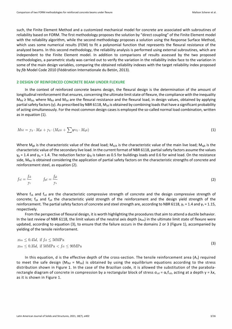
In this equation, d is the effective depth of the cross-section. The tensile reinforcement area (As) required to meet the safe design (MRd = MSd) is obtained by using the equilibrium equations according to the stress distribution shown in Figure 1. In the case of the Brazilian code, it is allowed the substitution of the parabola-rectangle diagram of concrete in compression by a rectangular block of stress σcd = αcfcd, acting at a depth y = λx, as it is shown in Figure 1.
Comparison of two FORM methodologies for reinforced concrete beams under flexure Maílson Scherer et al.
Latin American Journal of Solids and Structures, 2021, 18(7), e402 4/16
Figure 1: Strain and stress distribution in a reinforced concrete beam section
According to NBR 6118, the parameters αc and λ depend on the concrete strength. For Group I concretes (fck ≤ 50MPa, according to NBR 6118), αc = 0.85 and λ = 0.80. As it is illustrated in Figure 1, the equilibrium of the section can be written according to the equations (4) and (5).
λ0 : 0
2Sd cd
xM M b x d
(4)
0 : 0cd s ydF b x A f (5)
The equation (4) corresponds to a quadratic equation as a function of the neutral axis depth (x), being adopted, as the solution, the positive root contained within the domains of the cross-section. If x ≤ xlim, the ductility limits imposed by NBR 6118 are met, and the tensile reinforcement area is obtained by rewriting the equation (5) as:
cds
yd
b xA
f
(6)
In the case of x > xlim, a compressive reinforcement (As') is employed to ensure ductile behavior. Consequently, equations (4) and (5) must be rewritten to take account of its effects on the cross-section equilibrium. Only beams with simple reinforcement will be analyzed (As ≠ 0; As' = 0), so these equations are not presented for the cases where x > xlim.
3 NUMERICAL MODELING OF REINFORCED CONCRETE BEAMS
In this work, a Finite Element model was used to represent the flexural resistance of the analyzed beams. The modeling was performed using ANSYS software, employing the Finite Elements already available in the standard software library. An external customized subroutine (usermat), programmed in FORTRAN, was used to represent the mechanical model of concrete.
3.1 Finite elements
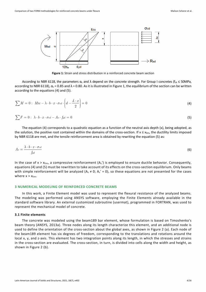
The concrete was modeled using the beam189 bar element, whose formulation is based on Timoshenko's beam theory (ANSYS, 2013a). Three nodes along its length characterize this element, and an additional node is used to define the orientation of the cross-section about the global axes, as shown in Figure 2 (a). Each node of the beam189 element has six degrees of freedom, corresponding to the translations and rotations around the local x, y, and z-axis. This element has two integration points along its length, in which the stresses and strains in the cross-section are evaluated. The cross-section, in turn, is divided into cells along the width and height, as shown in Figure 2 (b).
Comparison of two FORM methodologies for reinforced concrete beams under flexure Maílson Scherer et al.
Latin American Journal of Solids and Structures, 2021, 18(7), e402 5/16
Figure 2: (a) beam189 element for concrete modeling and (b) cross-section discretization of the beam189 element
(Adapted from ANSYS, 2013a)
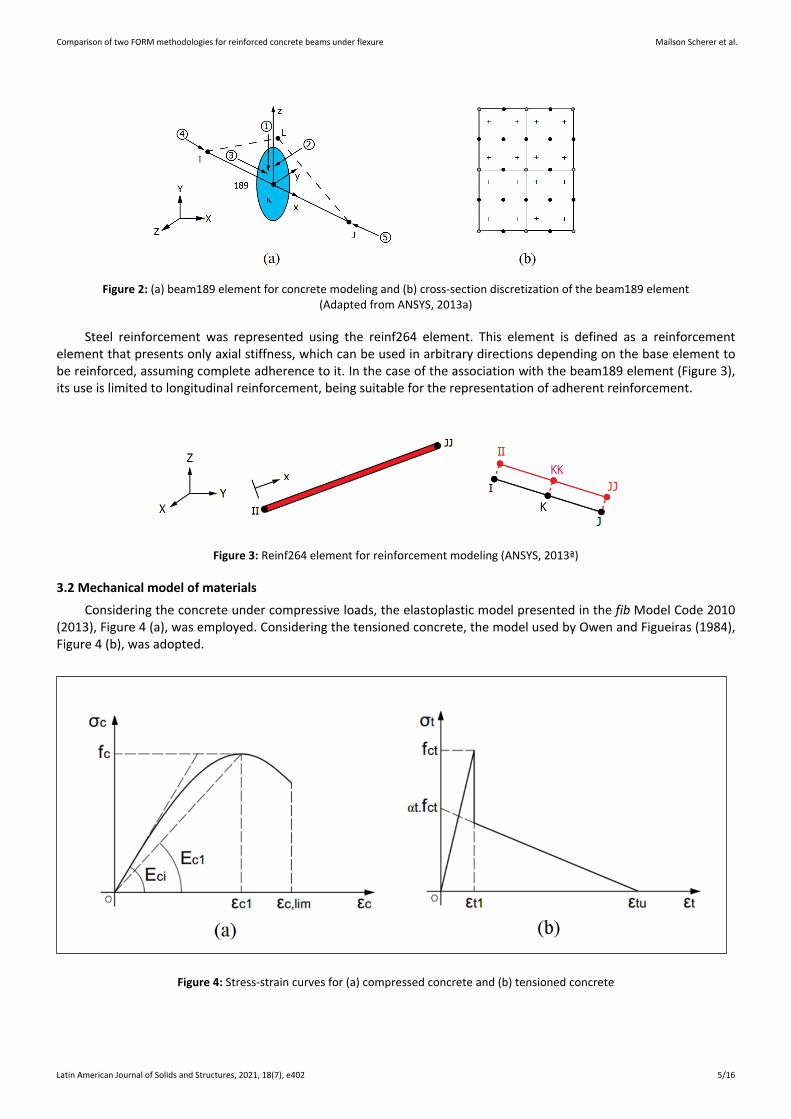
Steel reinforcement was represented using the reinf264 element. This element is defined as a reinforcement element that presents only axial stiffness, which can be used in arbitrary directions depending on the base element to be reinforced, assuming complete adherence to it. In the case of the association with the beam189 element (Figure 3), its use is limited to longitudinal reinforcement, being suitable for the representation of adherent reinforcement.
Figure 3: Reinf264 element for reinforcement modeling (ANSYS, 2013ª)
3.2 Mechanical model of materials
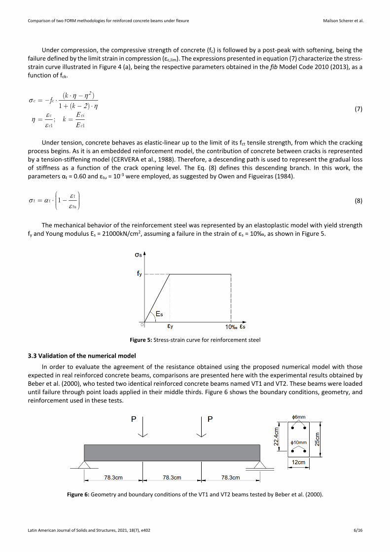
Considering the concrete under compressive loads, the elastoplastic model presented in the fib Model Code 2010 (2013), Figure 4 (a), was employed. Considering the tensioned concrete, the model used by Owen and Figueiras (1984), Figure 4 (b), was adopted.
Figure 4: Stress-strain curves for (a) compressed concrete and (b) tensioned concrete
Comparison of two FORM methodologies for reinforced concrete beams under flexure Maílson Scherer et al.
Latin American Journal of Solids and Structures, 2021, 18(7), e402 6/16
Under compression, the compressive strength of concrete (fc) is followed by a post-peak with softening, being the failure defined by the limit strain in compression (εc,lim). The expressions presented in equation (7) characterize the stress-strain curve illustrated in Figure 4 (a), being the respective parameters obtained in the fib Model Code 2010 (2013), as a function of fck.
2η ησ
2 ηε Εηε Ε1 1
( )
1 ( )
;
c c
c ci
c c
kf
k
k
(7)
Under tension, concrete behaves as elastic-linear up to the limit of its fct tensile strength, from which the cracking process begins. As it is an embedded reinforcement model, the contribution of concrete between cracks is represented by a tension-stiffening model (CERVERA et al., 1988). Therefore, a descending path is used to represent the gradual loss of stiffness as a function of the crack opening level. The Eq. (8) defines this descending branch. In this work, the parameters αt = 0.60 and εtu = 10-3 were employed, as suggested by Owen and Figueiras (1984).
εσ αε
1t
t ttu
(8)
The mechanical behavior of the reinforcement steel was represented by an elastoplastic model with yield strength fy and Young modulus Es = 21000kN/cm2, assuming a failure in the strain of εs = 10‰, as shown in Figure 5.
Figure 5: Stress-strain curve for reinforcement steel
3.3 Validation of the numerical model
In order to evaluate the agreement of the resistance obtained using the proposed numerical model with those expected in real reinforced concrete beams, comparisons are presented here with the experimental results obtained by Beber et al. (2000), who tested two identical reinforced concrete beams named VT1 and VT2. These beams were loaded until failure through point loads applied in their middle thirds. Figure 6 shows the boundary conditions, geometry, and reinforcement used in these tests.
Figure 6: Geometry and boundary conditions of the VT1 and VT2 beams tested by Beber et al. (2000).

Comparison of two FORM methodologies for reinforced concrete beams under flexure Maílson Scherer et al.
Latin American Journal of Solids and Structures, 2021, 18(7), e402 7/16
Specimens were tested to characterize the mechanical properties of the materials, obtaining, for concrete, fc = 3.36kN/cm2, fct = 0.29kN/cm2 and Eci = 3219.6kN/cm2. The tensile reinforcement was formed by CA-50 steel bars, with yield strength fy = 56.6kN/cm2, while the compressed reinforcement was formed by CA-60 steel bars, with yield strength fy = 73.8kN/cm2. The Young modulus of steel was taken as Es = 21438kN/cm2. The load-displacement plot obtained experimentally and numerically is shown in Figure 7.
Figure 7: Load-Displacement plot for the beams tested by Beber et al. (2000)
The failure loads P experimentally obtained for beams VT1 and VT2 were 23.7kN and 23.5kN, respectively, while the failure by the numerical model occurred in a P load of approximately 24.3kN. The relationship between the average of the experimental failures and the numerical failure results in 0.97, indicating that the numerical model provided a good approach for the failure load.
Additional comparisons between the proposed numerical model and experimental results can be found in the work of Scherer et al. (2019).
4 STRUCTURAL RELIABILITY
4.1 Generalities
It is necessary to express the performance of a structure mathematically, through the so-called performance function g(X), to evaluate the safety level against a limit state. In relation to an ultimate limit state, the performance function is written in terms of resistance (R) and load (S) in the safety margin format, assuming the generic two-dimensional form given in equation (9).
( , )g R S R S (9)
It should be noted that, in the case of concrete structures, the resistance R is a function of the mechanical properties of concrete and steel as well as the geometry of the element, and it can be written in the form R = R (fck, fyk, b, h, d, …). The load (S), on the other hand, is composed of the dead load (gk) and live load (qk) portions so that S = S (gk, qk). It is observed that the performance function will be n-dimensional, where n corresponds to the number of random variables involved in the problem. Faced with an ultimate limit state, g(X) delimits the safe domain (g(X) > 0), the failure domain (g(X) < 0) and the transition between these two regions (g(X) = 0), called the limit state.
4.2 First-Order Reliability Method
In many methods of reliability analysis, the safety level of a structure is expressed directly through the so-called reliability index β. The FORM is one of the most used methods for obtaining β, which is based on the transformation of the performance function g(X), written in the real space of the random variables, into a function g(X’), expressed in terms of equivalent normal, standardized and statistically independent random variables (HALDAR; MAHADEVAN, 2000). For a generic random variable Xi, it can be represented in the standard normalized system or reduced system as:
Comparison of two FORM methodologies for reinforced concrete beams under flexure Maílson Scherer et al.
Latin American Journal of Solids and Structures, 2021, 18(7), e402 8/16
µ σ'N Ni iX XX X (10)
Where μXN and σX
N are the mean and standard deviation. The superscript index “N” indicates that these are values for an equivalent normal function if the original probability distribution of the variable is different from the normal distribution. The reliability index β corresponds to the shortest distance between the failure surface in the standard normalized system, g(X’) = 0, and the origin of this system. Since the distance between the origin and a given point in the reduced system is expressed by D = (X'T‧X')1/2, the reliability index is obtained minimizing the distance D satisfying the restriction g(X) = 0. This point that minimizes D is called the most probable point or design point and is expressed by x’ *. Then, the reliability index of the structure is given by:
β
*
'*'
1
2*
'1
n
ii i
n
i i
gx
X
g
X
(11)
In equation (11), the notation “*” indicates that the vector of random variables and partial derivatives are evaluated at the design point. By the chain rule of differentiation, and the absence of correlation, the partial derivatives of g(X’) can be assessed by equation (12).
σ' '
i NXi
i ii i
Xg g g
X XX X
(12)
As the design point is not known a priori, the reliability index β is obtained by successive approximations, being used in this work the improved Hasofer & Lind - Rackwitz & Fiessler algorithm (iHLRF), presented by Zhang and Der Kiureghian (1995). The iHLRF algorithm introduces a line search in the direction aimed by the well-known HLRF (RACKWITZ; FIESSLER, 1978), where the optimal step size is found using the Armijo rule and a merit function that balances β and g(X).
4.3 Response Surface Method
The Response Surface Method (RSM) is based on the polynomial approximation of a function according to the
regression of sample results. This technique is particularly useful in reliability analyzes using the Finite Element Method, in which a set of model input parameters generates sample results for each numerical simulation (MELCHERS; BECK, 2018).
There are several sampling techniques for the construction of a polynomial in the Response Surface Method. In this paper, the Central Composite Design sampling technique was used (MONTGOMERY, 2012). This technique consists of sampling each random variable in five levels of probability pi (i = 1, 2, ..., 5). By combining each random variable at the different levels of probability, a set of (1 + 2n + 2n) sample points are obtained, from which, by statistical regression, the approximate polynomial function is fitted. For the case of a quadratic function with crossed terms, it can be represented generically by equation (13).
0
1 1 1i i ij i j
n n n
i i j
y a a x a x x
(13)
5 RELIABILITY OF REINFORCED CONCRETE BEAMS UNDER FLEXURE
5.1 Configuration of the analyzed beams
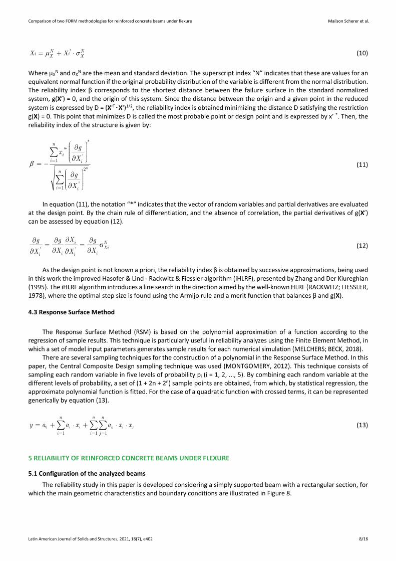
The reliability study in this paper is developed considering a simply supported beam with a rectangular section, for which the main geometric characteristics and boundary conditions are illustrated in Figure 8.
Comparison of two FORM methodologies for reinforced concrete beams under flexure Maílson Scherer et al.
Latin American Journal of Solids and Structures, 2021, 18(7), e402 9/16
Figure 8: Structural configuration of the analyzed beams
Based on the reference configuration, a parametric study was carried out by varying some critical parameters in the flexure design, more specifically: the characteristic compressive strength of concrete (fck = 25, 35, 45MPa); the height of the cross-section (h = 40, 50, 60cm); and the ratio between the live and dead portions of the characteristic load (r = qk/gk = 0.50, 1.00, 2.00). The total load applied was taken as (gk + qk) = 25kN/m, resulting in a set of 27 beams, identified according to the label V-fck-h-r and designed according to the procedure presented in section 2. For all analyzed beams, a fixed width of 20cm was considered. The design results of the beams are shown in Table 1.
Table 1: Random variables considered in the analyzes
Beam fck (MPa) fyk (kN/cm2) d (cm) x/d As (cm2)
V-25-40-r 25 50 36 0.416 8.39 V-25-50-r 25 50 46 0.235 6.04 V-25-60-r 25 50 56 0.153 4.78 V-35-40-r 35 50 36 0.279 7.87 V-35-50-r 35 50 46 0.162 5.85 V-35-60-r 35 50 56 0.107 4.69 V-45-40-r 45 50 36 0.211 7.63 V-45-50-r 45 50 46 0.125 5.76 V-45-60-r 45 50 56 0.083 4.64
It should be noted that as NBR 6118 adopts the same partial safety factors for dead load (γg) and live load (γq), the loading ratio (r) does not directly influence the design. Therefore, although 27 beams are analyzed, only 9 designs are required. Since all beams had a relative position of the neutral axis (x/d) < 0.45, the flexure ductility condition of NBR 6118 is met and As' = 0 for all cases.
5.2 Random variables
In this work, a set of 8 random variables, shown in Table 2, was considered. The main statistics and types of probability distribution were taken from Agrawal and Bhattacharya (2010), Szerszen et al. (2005), Biondini et al. (2004), Nowak and Szerszen (2003), JCSS (2001), Nowak and Collins (2000), Diniz and Frangopol (1997) and Galambos et al. (1982).
Table 2: Random variables considered in the analyzes
Variable Description Distribution ìx Vx
1 fc Compressive strength of concrete Normal fck/(1-1.645Vx) 0.10 2 fy Yield strength of reinforcement Normal fyk/(1-1.645Vx) 0.05 3 h Cross-section height Normal Nominal value 0.50/ìx 4 d' Distance of the reinforcement to the bottom of the beam cross-section Normal 4cm 0.50/ìx 5 G Dead load Normal 1.05gk 0.10 6 Q Live load Gumbel qk/(1+0.35Vx) 0.25 7 èR Uncertainty parameter of the resistance model Lognormal 1.0 0.05 8 èS Uncertainty parameter of the load model Lognormal 1.0 0.05
Comparison of two FORM methodologies for reinforced concrete beams under flexure Maílson Scherer et al.
Latin American Journal of Solids and Structures, 2021, 18(7), e402 10/16
5.3 Performance function
The performance function adopted in this work, related to the safety margin of the beams about the ultimate limit state of flexure, is represented by equation (14).
θ θ( ) R Sg R G Q X (14)
Where θR, θS, G, and Q are defined in Table 2, and the resistance R was obtained through two different methodologies. In Methodology 1, using the Python library presented by Titello (2020), the Finite Element Method software is coupled to the reliability analysis, making R an implicit function of fc, fy, h, d'. A forward finite difference scheme, as presented in equation (15), is used to compute the derivatives of the Finite Element model, which allows the use of the ANSYS software without any modification.
( ) ( ) ( )
i
g g g
X h
iX X h X
(15)
In equation (15) the vector hi is a vector of zeros, except for the ith term, where the finite difference step size h is used. The step size controls the approximation error, as the step shrinks the error goes down; however, since the Finite Element Method is a numerical approximated solution, a truly short step could not be reliable. In this paper, the step size is adopted as 2.0% of each variable mean (μxi). Hence, each FORM iteration using Methodology 1 requests at least 1+n+m evaluations of the Finite Element model, where n is the count of random variables which affects R, and m is the number of steps done by the line search, that is at best 1. In this work, n is 4, so the solution requires a minimum of 6 solves of the Finite Element model at each FORM iteration.
In Methodology 2, the resistance R was obtained using the RSM through a specific probability tool already available in the ANSYS software. Thus, considering the variables fc, fy, h, and d' (n = 4) used numerically to obtain the resistances, it was necessary to perform 25 evaluations of the Finite Element model to fit an explicit polynomial R = R (fc, fy, h, d'). An advantage of this methodology is the possibility of, once the resistance polynomial R was obtained, to put aside the Finite Element model, which, by its nature, is usually computationally costly, carrying out the reliability study from a performance function g(X) = θR‧R (fc, fy, h, d') - θS‧(G + Q), explicit for the eight random variables considered.
6 RELIABILITY INDEXES AND PARAMETRIC STUDY
Based on the two proposed methodologies, the reliability indexes were calculated for the 27 beams characterized in subsection 5.1. The obtained reliability indexes are shown in Table 3, where β1 and β2 correspond to the values obtained through methodologies 1 and 2, respectively.
Table 3: Reliability indexes obtained for the analyzed beams
Beam â1 â2 Beam â1 â2 Beam â1 â2
V-25-40-0.50 4.23 4.24 V-35-40-0.50 4.18 4.15 V-45-40-0.50 4.05 4.01 V-25-40-1.00 3.63 3.63 V-35-40-1.00 3.57 3.56 V-45-40-1.00 3.46 3.46 V-25-40-2.00 3.20 3.21 V-35-40-2.00 3.15 3.15 V-45-40-2.00 3.05 3.06 V-25-50-0.50 4.11 4.11 V-35-50-0.50 4.04 4.00 V-45-50-0.50 3.93 3.94 V-25-50-1.00 3.53 3.53 V-35-50-1.00 3.45 3.45 V-45-50-1.00 3.39 3.39 V-25-50-2.00 3.11 3.12 V-35-50-2.00 3.05 3.04 V-45-50-2.00 2.99 3.00 V-25-60-0.50 4.01 4.00 V-35-60-0.50 3.98 3.97 V-45-60-0.50 4.01 3.98 V-25-60-1.00 3.45 3.45 V-35-60-1.00 3.42 3.41 V-45-60-1.00 3.43 3.42 V-25-60-2.00 3.04 3.05 V-35-60-2.00 3.02 3.02 V-45-60-2.00 3.03 3.02
It is observed that, for the set of beams analyzed, the two proposed methodologies led to equivalent reliability indexes, as the more significant absolute difference is about 0.04. The closeness between the methodologies evidence that the flexural failure mode of the beams can be well represented by a second-order polynomial response surface, suppressing the computationally costly Finite Element model from the reliability analysis. In the analyses carried out
Comparison of two FORM methodologies for reinforced concrete beams under flexure Maílson Scherer et al.
Latin American Journal of Solids and Structures, 2021, 18(7), e402 11/16
below, it was decided to present the reliability indexes obtained through Methodology 1, as it employs the complete Finite Element model.
To determine the influence of some design parameters on the level of reliability reached by the analyzed beams, the parametric plots, illustrated in Figures 9 to 14 were constructed. To establish a conclusion regarding the level of reliability reached by these beams, it is presented in all plots the target reliability index βtarget = 3.8, suggested by the fib Model Code 2010 (2013) for a period of 50 years and considering failures with medium consequences.
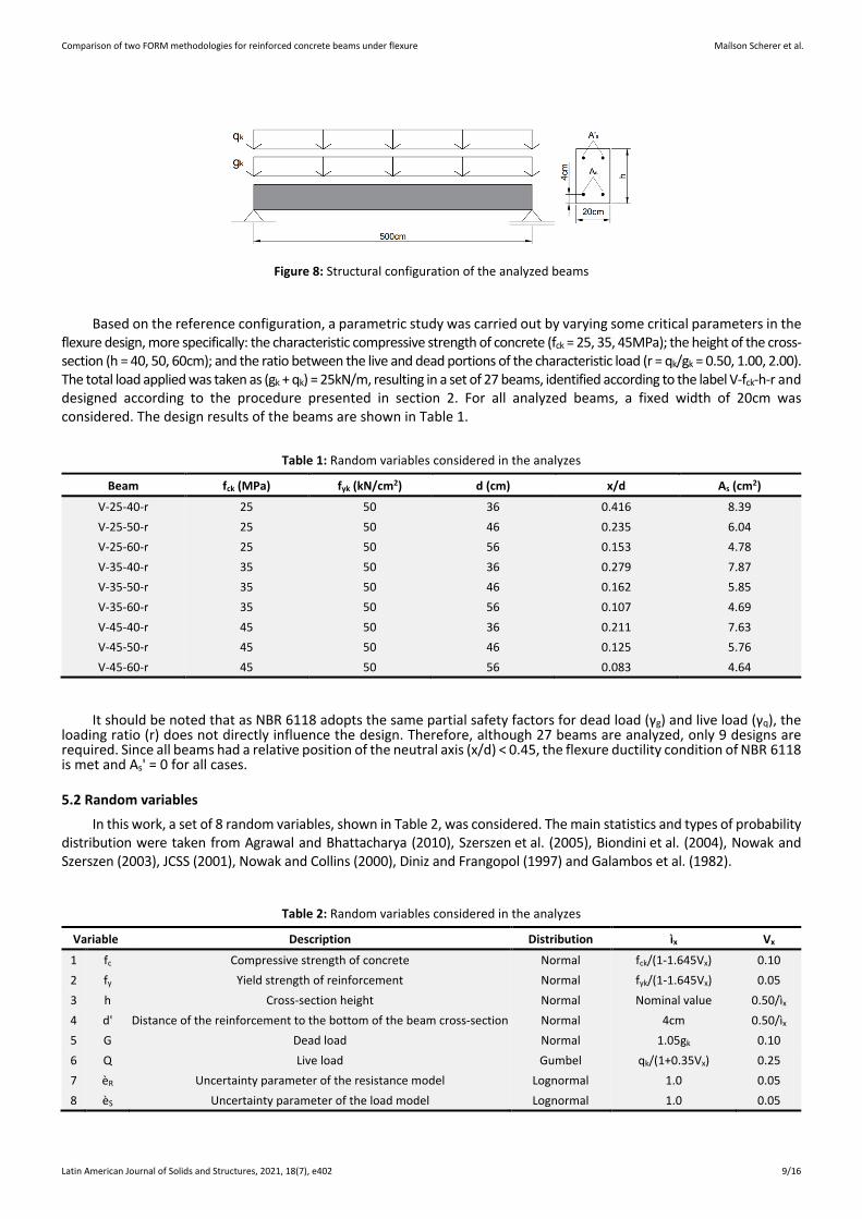
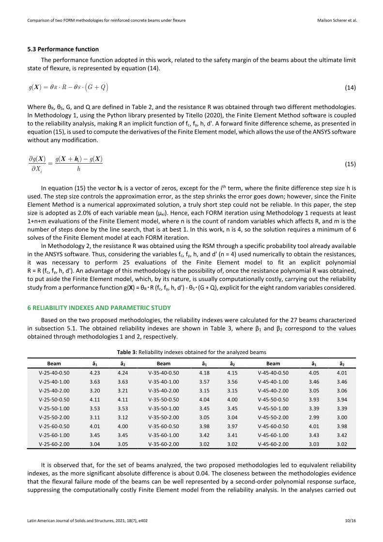
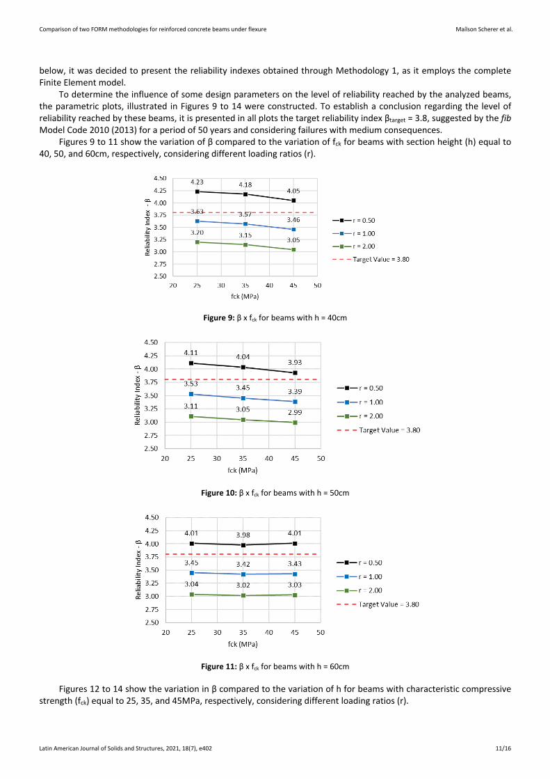
Figures 9 to 11 show the variation of β compared to the variation of fck for beams with section height (h) equal to 40, 50, and 60cm, respectively, considering different loading ratios (r).
Figure 9: β x fck for beams with h = 40cm
Figure 10: β x fck for beams with h = 50cm
Figure 11: β x fck for beams with h = 60cm
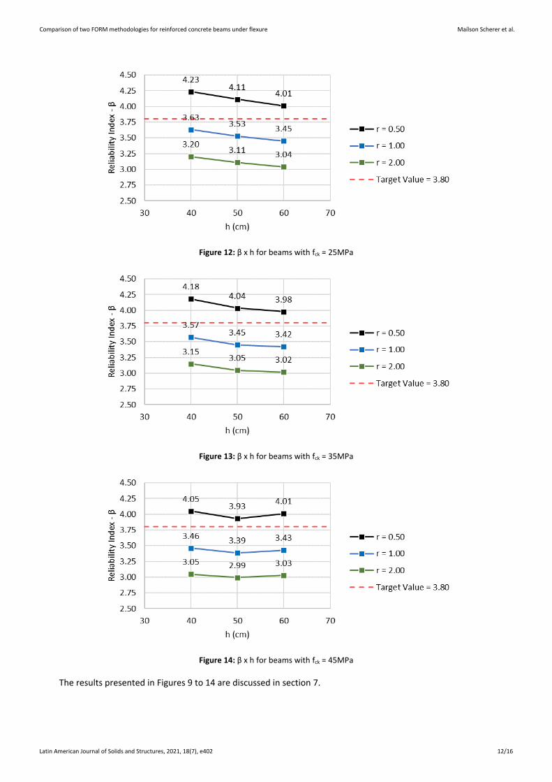
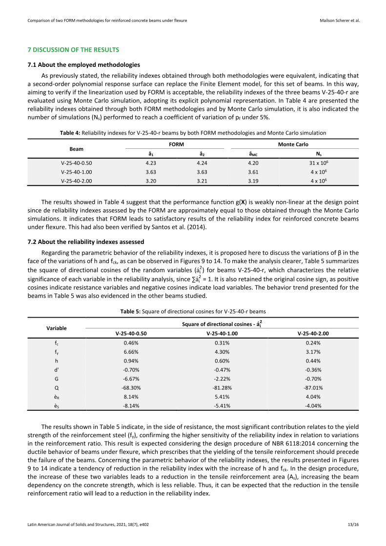
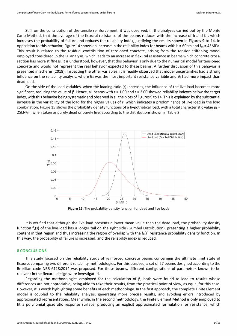
Figures 12 to 14 show the variation in β compared to the variation of h for beams with characteristic compressive strength (fck) equal to 25, 35, and 45MPa, respectively, considering different loading ratios (r).
Comparison of two FORM methodologies for reinforced concrete beams under flexure Maílson Scherer et al.
Latin American Journal of Solids and Structures, 2021, 18(7), e402 12/16
Figure 12: β x h for beams with fck = 25MPa
Figure 13: β x h for beams with fck = 35MPa
Figure 14: β x h for beams with fck = 45MPa
The results presented in Figures 9 to 14 are discussed in section 7.
Comparison of two FORM methodologies for reinforced concrete beams under flexure Maílson Scherer et al.
Latin American Journal of Solids and Structures, 2021, 18(7), e402 13/16
7 DISCUSSION OF THE RESULTS
7.1 About the employed methodologies
As previously stated, the reliability indexes obtained through both methodologies were equivalent, indicating that a second-order polynomial response surface can replace the Finite Element model, for this set of beams. In this way, aiming to verify if the linearization used by FORM is acceptable, the reliability indexes of the three beams V-25-40-r are evaluated using Monte Carlo simulation, adopting its explicit polynomial representation. In Table 4 are presented the reliability indexes obtained through both FORM methodologies and by Monte Carlo simulation, it is also indicated the number of simulations (Ns) performed to reach a coefficient of variation of pf under 5%.
Table 4: Reliability indexes for V-25-40-r beams by both FORM methodologies and Monte Carlo simulation
Beam FORM Monte Carlo
â1 â2 âMC Ns
V-25-40-0.50 4.23 4.24 4.20 31 x 106 V-25-40-1.00 3.63 3.63 3.61 4 x 10⁶ V-25-40-2.00 3.20 3.21 3.19 4 x 10⁶
The results showed in Table 4 suggest that the performance function g(X) is weakly non-linear at the design point since de reliability indexes assessed by the FORM are approximately equal to those obtained through the Monte Carlo simulations. It indicates that FORM leads to satisfactory results of the reliability index for reinforced concrete beams under flexure. This had also been verified by Santos et al. (2014).
7.2 About the reliability indexes assessed
Regarding the parametric behavior of the reliability indexes, it is proposed here to discuss the variations of β in the face of the variations of h and fck, as can be observed in Figures 9 to 14. To make the analysis clearer, Table 5 summarizes the square of directional cosines of the random variables (ái
2) for beams V-25-40-r, which characterizes the relative significance of each variable in the reliability analysis, since ∑ái
2 = 1. It is also retained the original cosine sign, as positive cosines indicate resistance variables and negative cosines indicate load variables. The behavior trend presented for the beams in Table 5 was also evidenced in the other beams studied.
Table 5: Square of directional cosines for V-25-40-r beams
Variable Square of directional cosines - ái
2
V-25-40-0.50 V-25-40-1.00 V-25-40-2.00
fc 0.46% 0.31% 0.24% fy 6.66% 4.30% 3.17% h 0.94% 0.60% 0.44% d' -0.70% -0.47% -0.36% G -6.67% -2.22% -0.70% Q -68.30% -81.28% -87.01% èR 8.14% 5.41% 4.04% èS -8.14% -5.41% -4.04%
The results shown in Table 5 indicate, in the side of resistance, the most significant contribution relates to the yield strength of the reinforcement steel (fy), confirming the higher sensitivity of the reliability index in relation to variations in the reinforcement ratio. This result is expected considering the design procedure of NBR 6118:2014 concerning the ductile behavior of beams under flexure, which prescribes that the yielding of the tensile reinforcement should precede the failure of the beams. Concerning the parametric behavior of the reliability indexes, the results presented in Figures 9 to 14 indicate a tendency of reduction in the reliability index with the increase of h and fck. In the design procedure, the increase of these two variables leads to a reduction in the tensile reinforcement area (As), increasing the beam dependency on the concrete strength, which is less reliable. Thus, it can be expected that the reduction in the tensile reinforcement ratio will lead to a reduction in the reliability index.
Comparison of two FORM methodologies for reinforced concrete beams under flexure Maílson Scherer et al.
Latin American Journal of Solids and Structures, 2021, 18(7), e402 14/16
Still, on the contribution of the tensile reinforcement, it was observed, in the analyzes carried out by the Monte Carlo Method, that the average of the flexural resistance of the beams reduces with the increase of h and fck, which increases the probability of failure and reduces the reliability index, justifying the results shown in Figures 9 to 14. In opposition to this behavior, Figure 14 shows an increase in the reliability index for beams with h = 60cm and fck = 45MPa. This result is related to the residual contribution of tensioned concrete, arising from the tension-stiffening model employed considered in the FE analysis, which leads to an increase in flexural resistance in beams which concrete cross-section has more stiffness. It is understood, however, that this behavior is only due to the numerical model for tensioned concrete and would not represent the real behavior expected to these beams. A further discussion of this behavior is presented in Scherer (2018). Inspecting the other variables, it is readily observed that model uncertainties had a strong influence on the reliability analysis, where θR was the most important resistance variable and θS had more impact than dead load.
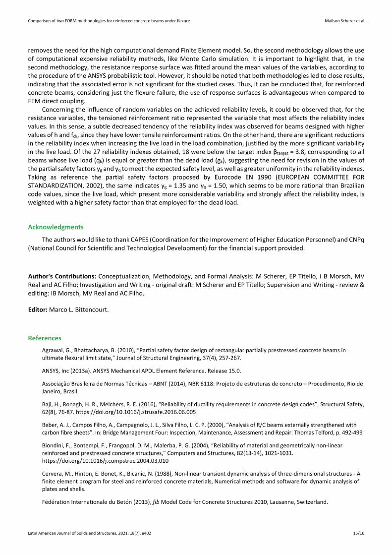
On the side of the load variables, when the loading ratio (r) increases, the influence of the live load becomes more significant, reducing the value of β. Hence, all beams with r = 1.00 and r = 2.00 showed reliability indexes below the target index, with this behavior being systematic and observed in all the plots of Figures 9 to 14. This is explained by the substantial increase in the variability of the load for the higher values of r, which indicates a predominance of live load in the load combination. Figure 15 shows the probability density functions of a hypothetical load, with a total characteristic value pk = 25kN/m, when taken as purely dead or purely live, according to the distributions shown in Table 2.
Figure 15: The probability density function for dead and live loads
It is verified that although the live load presents a lower mean value than the dead load, the probability density function fS(s) of the live load has a longer tail on the right side (Gumbel Distribution), presenting a higher probability content in that region and thus increasing the region of overlap with the fR(r) resistance probability density function. In this way, the probability of failure is increased, and the reliability index is reduced.
8 CONCLUSIONS
This study focused on the reliability study of reinforced concrete beams concerning the ultimate limit state of flexure, comparing two different reliability methodologies. For this purpose, a set of 27 beams designed according to the Brazilian code NBR 6118:2014 was proposed. For these beams, different configurations of parameters known to be relevant in the flexural design were investigated.
Regarding the methodologies employed for the calculation of β, both were found to lead to results whose differences are not appreciable, being able to take their results, from the practical point of view, as equal for this case. However, it is worth highlighting some benefits of each methodology. In the first approach, the complete Finite Element model is coupled to the reliability analysis, generating more precise results, and avoiding errors introduced by approximated representations. Meanwhile, in the second methodology, the Finite Element Method is only employed to fit a polynomial quadratic response surface, producing an explicit approximated formulation for resistance, which
Comparison of two FORM methodologies for reinforced concrete beams under flexure Maílson Scherer et al.
Latin American Journal of Solids and Structures, 2021, 18(7), e402 15/16
removes the need for the high computational demand Finite Element model. So, the second methodology allows the use of computational expensive reliability methods, like Monte Carlo simulation. It is important to highlight that, in the second methodology, the resistance response surface was fitted around the mean values of the variables, according to the procedure of the ANSYS probabilistic tool. However, it should be noted that both methodologies led to close results, indicating that the associated error is not significant for the studied cases. Thus, it can be concluded that, for reinforced concrete beams, considering just the flexure failure, the use of response surfaces is advantageous when compared to FEM direct coupling.
Concerning the influence of random variables on the achieved reliability levels, it could be observed that, for the resistance variables, the tensioned reinforcement ratio represented the variable that most affects the reliability index values. In this sense, a subtle decreased tendency of the reliability index was observed for beams designed with higher values of h and fck, since they have lower tensile reinforcement ratios. On the other hand, there are significant reductions in the reliability index when increasing the live load in the load combination, justified by the more significant variability in the live load. Of the 27 reliability indexes obtained, 18 were below the target index βtarget = 3.8, corresponding to all beams whose live load (qk) is equal or greater than the dead load (gk), suggesting the need for revision in the values of the partial safety factors γg and γq to meet the expected safety level, as well as greater uniformity in the reliability indexes. Taking as reference the partial safety factors proposed by Eurocode EN 1990 (EUROPEAN COMMITTEE FOR STANDARDIZATION, 2002), the same indicates γg = 1.35 and γq = 1.50, which seems to be more rational than Brazilian code values, since the live load, which present more considerable variability and strongly affect the reliability index, is weighted with a higher safety factor than that employed for the dead load.
Acknowledgments
The authors would like to thank CAPES (Coordination for the Improvement of Higher Education Personnel) and CNPq (National Council for Scientific and Technological Development) for the financial support provided.
Author's Contributions: Conceptualization, Methodology, and Formal Analysis: M Scherer, EP Titello, I B Morsch, MV Real and AC Filho; Investigation and Writing - original draft: M Scherer and EP Titello; Supervision and Writing - review & editing: IB Morsch, MV Real and AC Filho.
Editor: Marco L. Bittencourt.
References
Agrawal, G., Bhattacharya, B. (2010), “Partial safety factor design of rectangular partially prestressed concrete beams in ultimate flexural limit state,” Journal of Structural Engineering, 37(4), 257-267.
ANSYS, Inc (2013a). ANSYS Mechanical APDL Element Reference. Release 15.0.
Associação Brasileira de Normas Técnicas – ABNT (2014), NBR 6118: Projeto de estruturas de concreto – Procedimento, Rio de Janeiro, Brasil.
Baji, H., Ronagh, H. R., Melchers, R. E. (2016), “Reliability of ductility requirements in concrete design codes”, Structural Safety, 62(8), 76-87. https://doi.org/10.1016/j.strusafe.2016.06.005
Beber, A. J., Campos Filho, A., Campagnolo, J. L., Silva Filho, L. C. P. (2000), “Analysis of R/C beams externally strengthened with carbon fibre sheets”. In: Bridge Management Four: Inspection, Maintenance, Assessment and Repair. Thomas Telford, p. 492-499
Biondini, F., Bontempi, F., Frangopol, D. M., Malerba, P. G. (2004), “Reliability of material and geometrically non-linear reinforced and prestressed concrete structures,” Computers and Structures, 82(13-14), 1021-1031. https://doi.org/10.1016/j.compstruc.2004.03.010
Cervera, M., Hinton, E. Bonet, K., Bicanic, N. (1988), Non-linear transient dynamic analysis of three-dimensional structures - A finite element program for steel and reinforced concrete materials, Numerical methods and software for dynamic analysis of plates and shells.
Fédération Internationale du Betón (2013), fib Model Code for Concrete Structures 2010, Lausanne, Switzerland.
Comparison of two FORM methodologies for reinforced concrete beams under flexure Maílson Scherer et al.
Latin American Journal of Solids and Structures, 2021, 18(7), e402 16/16
Diniz, S. M. C., Frangopol, D. M. (1997), “Reliability Bases of High-Strength Concrete Columns”, Journal of Engineering Mechanics,123(10), 1375-1381. https://doi.org/10.1061/(ASCE)0733-9445(1997)123:10(1375)
European Committee For Standardization (2002), Eurocode 0: Basis of structural design, Brussels, Belgium.
Galambos, E. V., Ellingwood, B., MacGregor, J. G., Cornel, C. A. (1982), “Probability-based load criteria: assessment of current design practice”, Journal of the Structural Division, 108(5), 959-977.
Haldar, A., Mahadevan, S. (2000), Probability, Reliability, and Statistical Methods in Engineering Design, John Wiley & Sons, New York, EUA.
Joint Committee on Structural Safety (2001), JCSS Probabilistic Model Code, Lyngby, Denmark.
Melchers, R. E., Beck. A. T. (2018), Structural Reliability Analysis and Prediction, John Wiley & Sons, New York, EUA.
Montgomery (2012), Design and analysis of Experiments, John Wiley & Sons, New York, EUA.
Nogueira, C. G., Pinto, M. D. T. (2016), “Safety variability of reinforced concrete beams subjected to bending moment considering the NBR 6118:2014 safety partial factors”, IBRACON Structures and Materials Journal,9(5), 682-709. https://doi.org/10.1590/S1983-41952016000500003
Nowak, A. S., Collins, K. R. (2000), Reliability of Structures, McGraw-Hill Companies, Inc., New York, EUA.
Nowak, A. S., Szerszen, M. M. (2003), “Calibration of Design Code for Buildings (ACI 318): Part 1 – Statistical Models for Resistance”, ACI Structural Journal,100(3), 377-382. https://dx.doi.org/ 10.14359/12613
Owen, D. R. J. and Figueiras, J. A. (1984), “Ultimate load analysis of reinforced concrete plates and shells including geometric non-linear effects”, Finite Element Software for Plates and Shells, by E. Hinton and D.R.J. Owen, Pineridge Press, London.
Rackwitz, F., Fiessler, B. (1978), “Structural Reliability Under Combined Random Load Sequences”, Computers and Structures,9(5), 484-494. https://doi.org/10.1016/0045-7949(78)90046-9
Ribeiro, S. E. C., Diniz, S. M. C. (2013), “Reliability-base design recommendations for FRP-reinforced concrete beams”, Engineering Structures, 52(24), 273-283. https://doi.org/10.1016/j.engstruct.2013.02.026
Santiago, W. C., Kroetz, H. M., Stuchi, F. R., Santos, S. H. C., Beck, A. T. (2020), “Reliability-based calibration of main Brazilian structural design codes”, Latin American Journal of Solids and Structures, 17(1), 1-28. https://doi.org/10.1590/1679-78255754
Santos, D. M., Stuchi, F. R., Beck, A. T. (2014), “Reliability of beams designed in accordance with Brazilian codes”, IBRACON Structures and Materials Journal, 7(5), 723-746. http://dx.doi.org/10.1590/S1983-41952014000500002
Scherer, M., Morsch, I. B., Real, M. V. (2019), “Reliability of reinforced concrete beams designed in accordance with Brazilian code NBR-6118:2014”, IBRACON Structures and Materials Journal,12(5), 1086-1125. http://dx.doi.org/10.1590/s1983-41952019000500007
Scherer, M. (2018), “Evaluation of the reliability of reinforced concrete beams by the Finite Element Method”. Master’s degree thesis, Federal University of Rio Grande do Sul, Porto Alegre, Brazil.
Szerszen, M. M., Szwed, A., Nowak, A. S. (2005), “Reliability Analysis for Eccentrically Loaded Columns”, ACI Structural Journal,102(5), 676-688. http://dx.doi.org/10.14359/14663
Titello, E. P. (2020), dutitello/parAnsys: PARANSYS: Python pArametric Reliability Analysis on ANSYS. Version 0.1. Zenodo. https://doi.org/10.5281/zenodo.4161579
Zhang Y., Der Kiureghian A. (1995), “Two Improved Algorithms for Reliability Analysis”, Reliability and Optimization of Structural Systems by R. Rackwitz, G. Augusti, A. Borri (eds), Springer, Boston, MA. https://doi.org/10.1007/978-0-387-34866-7_32