Embed Size (px)
Citation preview
Research ArticleComparisons of Two Typical Specialized Finite ElementPrograms for Mechanical Analysis of Cement Concrete Pavement
Hanyan Gu ,1,2,3 Xin Jiang ,1,2,3 Zhenkun Li,1,2,3 Kang Yao,1,2,3 and Yanjun Qiu 1,2,3
1School of Civil Engineering, Southwest Jiaotong University, Chengdu 610031, China2Highway Engineering Key Laboratory of Sichuan Province, Southwest Jiaotong University, Chengdu 610031, China3MOE Key Laboratory of High-speed Railway Engineering, Southwest Jiaotong University, Chengdu 610031, China
Correspondence should be addressed to Xin Jiang; [email protected]
Received 9 July 2019; Revised 28 August 2019; Accepted 6 September 2019; Published 25 September 2019
Academic Editor: Alessandro Della Corte
Copyright © 2019 Hanyan Gu et al. ,is is an open access article distributed under the Creative Commons Attribution License,which permits unrestricted use, distribution, and reproduction in any medium, provided the original work is properly cited.
,e structural mechanics analysis of the Portland cement concrete pavement (PCCP) is considerably complicated and distinctive.From the application viewpoint, the capabilities and characteristics of two typical professional finite element software products,named KENSLABS and EverFE, are analyzed. ,e similarities and differences between these two programs are compared. ,ecomparisons focus on some key factors of modeling and solution strategies, such as element type, meshing, traffic load andtemperature curling, boundary conditions, and contact conditions. Based on one specific case example, the two software productswere conducted to demonstrate their main functions.,e research results clarify the performance of the two software products forstructural analysis of cement concrete pavement and indicate each application conditions from their respective features, which canprovide valuable references for software users and program developers.
1. Introduction
As an important part in the transportation infrastructure,Portland cement concrete pavement (PCCP) is generallyregarded as a layered system composed of surface course,base course, subbase course, and bed course built on sub-grade [1]. Some of the major features of PCCP are sum-marized below: (1) It consists of several different materials,such as fines, coarse aggregate, cement-stabilized material,and cement concrete, which are of strong nonlinearity,nonuniformity, and anisotropy [2]. (2),e pavement systemis repeatedly subjected to various wheel/axle load combi-nations with different speeds. ,ese loads may be vertical orhorizontal. In addition to static effects, the load dynamiceffects such as movement, impact, or vibration are verystrong [3, 4]. Furthermore, the positions of the loads are notfixed during the travel time. (3) As been exposed to naturalcircumstances, Portland cement concrete slabs experienceseasonal and daily temperature changes deeply, while theperformance of subgrade is also severely dependent on waterand temperature conditions [5–8]. (4) ,e plate should be
discontinuous due to longitudinal and transverse jointsdistributed between adjacent slabs. Transverse joints areoften doweled for better load transfer, and adjacent slabsmay be tied at longitudinal joints. (5) Many distresses, in-cluding blowup, corner break, pumping and water bleeding,transverse and longitudinal cracks, and joint faulting, mayoccur frequently under the comprehensive influence oftraffic loads and temperature changes, thus resulting in thesharp decrease of pavement performance [1].
Carrying out the analysis of the PCCP structure cancomprehensively obtain the mechanical response and failuremechanism under the traffic load, temperature gradient, andother environmental factors. It is of great significance forreasonable measures determination, design, and construc-tion technology improvement. Traditional available ana-lytical solutions may not realistically account for complexloads, mixed boundary conditions, and arbitrary geometry[9]. With the development of electronic computers, manydifferent numerical methods have been employed in therigid pavement structure analysis in the past several decades,such as finite element method (FEM), discrete element
HindawiMathematical Problems in EngineeringVolume 2019, Article ID 9178626, 11 pageshttps://doi.org/10.1155/2019/9178626
method (DEM), boundary element method (BEM), andfinite difference method (FDM). However, the finite elementmethod is undoubtedly one of the mainstream methods dueto its outstanding flexibility and acceptability. As early as1965, Cheung and Zienkiewicz developed finite elementmethods for analyzing slabs on elastic foundations of bothliquid and solid types [10].,e finite element method (FEM)is useful for both rigid pavement researchers and designerswho must perform complex mechanics-based analyses ofrigid pavement systems. Many special-purpose programsbased on FEM were developed to conduct cement concretepavement structure mechanical analysis with enough ac-curacy and higher efficiency. ,ough general-purpose finiteelement packages, such as ABAQUS and ANSYS, havepowerful ability to handle with complex problems [11–14],they can be difficult to learn and use effectively, modelgeneration can be time-consuming, simulation times can belong in the case of 3D analysis, and extracting results ofinterest can be difficult. ,erefore, the particularity andcomplexity of the analysis of the PCCP structure are difficultto be illustrated in details. In the meantime, some special-purpose software packages were developed for PCCPstructural analysis because they address the shortcomings ofboth the previously described approaches. ,ere are manyexcellent software products currently available for cementconcrete pavement structure analysis, including KENSLABS[15], WESLIQID and WESLAYER [16], ILLI-SLAB [17, 18](called ISLAB2000 from 2000 [19]), JSLAB [20, 21], RISC[22, 23], DIPLOMAT [24], FEACONS-IV [25], KOLA [26],and EverFE [27]. Most of them are on the basis of the two-dimensional finite element method due to the limitation ofhardware requirements and computing time. KENSLABS, a2D program developed by Professor Yang H. Huang ofUniversity of Kentucky, and EverFE, a 3D program de-veloped by Professor Bill Davids of University of Maine, arequite distinctive among them.,ey play a representative roleto some degree in the history of PCCP mechanical analysisand have been utilized widely and successfully in the con-crete pavement industry [5, 28–31].
,e finite element analysis (FEA) studies of the pave-ment structure currently available emphasize the basictheoretical aspects of the method with applications beingpresented to demonstrate the essential practical nature ofthe technique. However, as anyone who has ever tried todevelop a finite element program will testify, there is anenormous gulf between the basic theory and a workingcomputer code. In this paper, two typical finite elementsoftware packages for PCCP analysis—KENSLABS andEverFE—will be introduced to conduct comparisons fromapplication viewpoints; that is, numerical model estab-lishment, calculation solution strategy, and results post-processing will be investigated in details. ,en, one specificcase example is going to be solved by both two programs,respectively, and the resulting differences between themwill be discussed. For one thing, this study will helpsoftware users to improve these two programs applicationlevel. For another, the program developers will get valuablereferences from these comparisons to release more pow-erful specialized software. Finally, this study may improve
numerical simulation implementation of the PCCP structureby large general-purpose finite element software packageswith theory development [32–35].
2. Comparison of EverFE and KENSLABS
Similar to other finite element programs, both KENSLABSand EverFE contain three core components to conductPCCP numerical analysis: numerical model establishment(preprocessing), calculation and solution, results output,and visualization (postprocessing). ,e details will becircumstantiated below. It should be pointed out that theDOS version of KENSLABS and the Windows version ofEverFE 2.24 are discussed for parallel comparisons in thisstudy while there are several versions available currently.
Macroscopically, both programs can be applied to amaximum of 9 slabs and 12 joints. However, surface coursecan be considered as one-layer or two-layer slabs inKENSLABS. ,ere are three different types of foundationsthat can be assumed: dense liquid foundation (Winklerfoundation), solid foundation, and layer foundation.When a dense liquid foundation is introduced, even thenonuniformity of the foundation can be taken into ac-count. However, if a base or a subbase course is taken intoconsideration, a layer foundation is recommended formore realistic results. Symmetry of the model can be fullyutilized in KENSLABS. As a result, the half-structure orquarter structure can be introduced in analysis to savecalculation time and data storage. But the slabs must berectangular, and this is one minor limitation.
On the contrary, one-layer slab is a default setting inEverFE, and up to 3 elastic base layers can be specified. Eachone of them is assumed to be perfectly bonded to theadjacent layer, and the uppermost layer can be completelyunbonded with the slab. A tensionless or tension-sup-porting dense liquid foundation underlies the bottom-mostlayer. ,e effects of linear or nonlinear aggregate interlockshear transfer can be simulated at the joints. Two types ofelements are utilized to discretize the dowel and tie bars,and the looseness and misalignment of the dowel bars canbe modeled perfectly. Every dowel can be precisely locatedacross the transverse joints in the numerical model.Contrary to KENSLABS, the full model must be adopted inEverFE. ,e slabs can be rectangular or quadrilateral, andthis is more flexible than KENSLABS.
2.1. Element Type and Mesh. ,anks to the plate theory,KENSLABS was designed as a two-dimensional (2D) FEMprogram. ,e slabs only need to be meshed on the plane.Nonetheless, it needs to be meshed by inputting the gridlines locations of each slab manually. When dividing theslabs into rectangular finite elements, it is not necessary touse very fine divisions. However, the regions near the load oraround the area of interest must be meshed finer. In ad-dition, due to the limitations of KENSLABS itself, the totalnumber of nodes is limited to 420. Up to 15 nodes in the xdirection and 15 nodes in the y direction can be set in eachslab. To obtain more accurate results, the length-to-width
2 Mathematical Problems in Engineering
ratio of any element should not be greater than 5. ,edimension of the overall stiffness matrix is limited to70,000. If the overall stiffness matrix dimension exceeds70,000, an iterative method is activated automatically tosolve the simultaneous equations. ,ere are one plateelement, three types (liquid, solid, and layer) of foundationelements, and one dowel bar element in KENSLABS.
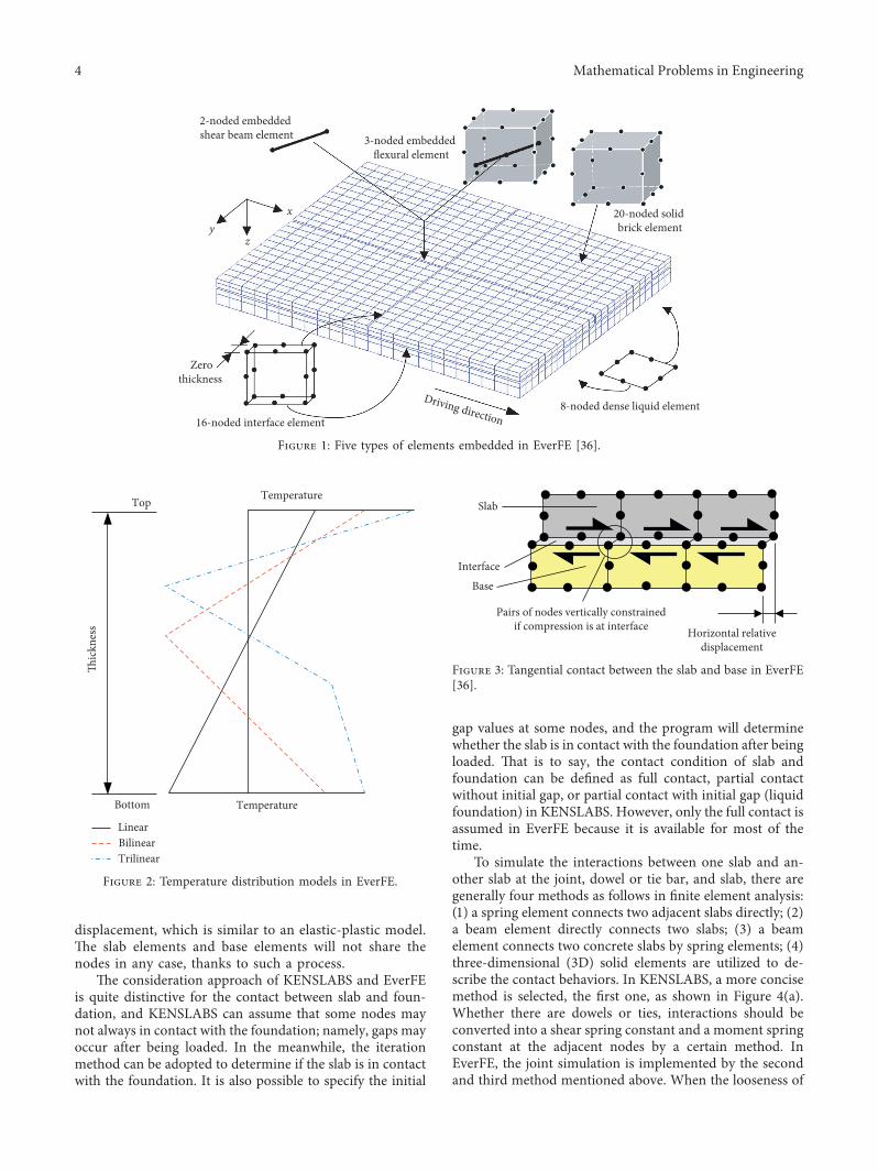
,e slabs will be divided evenly by EverFE accordingto the element number of three directions. Similar toKENSLABS, it is also required that the length-to-widthratio of elements needs to be less than 5. ,e total numberof elements is theoretically unlimited in EverFE, and thesolved problem scale only depends on the computerhardware configurations. Five types of elements areembedded in EverFE, as shown in Figure 1: 20-nodedquadratic solid element for discretizing the slabs andelastic base layers, 8-noded planar quadratic element tosimulate the dense liquid foundation, 16-noded quadraticinterface element to implement aggregate interlock andthe slab-base interactions, 3-noded embedded flexibleelement, and 2-noded shear beam element for discretizingdowel and tie bars.
2.2. Traffic Load and Temperature Gradient. Exposed tonatural circumstances, the cement concrete pavement isaffected by traffic loads, temperature gradient, and moisturegradient. Different specialized software products treat thesefactors differently. ,e following are some tips about thedifferences when using these two programs.
In terms of loads, rectangular uniformly distributedvertical loads, concentrated forces, and moments can beapplied to the KENSLABS model. If uniformly distributedvertical loads are involved, the locations for four sides ofthe rectangular contact area need to be input manually.However, it is necessary to set the contact pressure for eachwheel load area; namely, they can be different from eachother. ,e coordinates of each contact area and the contactpressure should be determined according to the defaultcoordinate system and axle weight prior to simulation.,en, the complex axle combinations can be considered inKENSLABS by adjusting the contact pressure and locationsof each loading area, respectively. For fatigue cracking ofthe slabs caused by load reputations, damage analysis canbe carried out to predict the cracking index and design lifein KENSLABS. In EverFE, some commonly used axlecombinations have been embedded, such as single wheel,single-wheel axle, dual-wheel axle, single-wheel tandem,and dual-wheel tandem. For each axle combination, loadparameters can be adjusted according to the contact area,dual spacing, tandem spacing, and spacing between thecenter of the two sets of dual tires if needed. ,e contactpressure is calculated automatically on the basis of thecontact area and the axle weight; namely, the contactpressure of each contact area should be same. Compared toKENSLABS, concentrated forces or moments cannot bemodeled in EverFE.
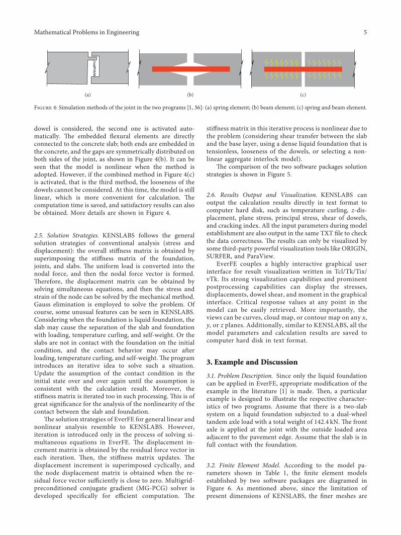
In the aspect of thermal load, the linear temperaturedistribution along the thickness is the only selection in
KENSLABS to simulate the thermal load. In contrast,temperature distribution can be linear or nonlinear inEverFE. Up to four temperature change points along thethickness can be defined; i.e., the temperature distribu-tion would be linear, bilinear, or trilinear (illustrated inFigure 2). At the same time, the values at the controlpoints are absolute temperatures specified arbitrarily,rather than relative temperature difference. ,erefore, theinfluence of the overall expansion or contraction on theslab with joint shear transfer can be studied. ,is wouldbe an equivalent method to simulate the early shrinkageeffect of PCCP in the meanwhile.
2.3. Boundary Conditions. In KENSLABS, x and y di-rections’ (the horizontal direction) displacements of thenodes are fixed, due to the basic assumptions of the platetheory. ,e foundation (dense liquid foundation, layerfoundation, or solid foundation) provides the z directionconstraint. It occurs when the slabs and foundation are incontact, which can be judged by the program itself or definedby users.
EverFE differs its default boundary conditionsdepending on whether there is an elastic base layer: (1) Ifthe base layer is involved in the model, the shear stiffnessof the slab-base interface element constrains the dis-placement of the slab in the x and y directions, and the zdirection constraint is obtained by contact with the baselayer. ,e rigid body motion of the base layer and thesubbase layer is prevented by limiting the displacementin the x and y directions of a node on the x-face andlimiting the x-displacement of a second node on the x-face. (2) If the slabs are modeled directly on a denseliquid foundation, i.e., no base layer is modeled, each slabis restrained against x and y directions’ displacements atone node on its x-face and against x-direction dis-placement at a second node on its x-face to prevent rigidbody motion of each slab. Vertical support is provided bythe dense liquid foundation. ,e z direction supportconstraints of the overall system are provided by denseliquid foundation. ,ese conditions are always present bydefault and are not graphically displayed during mod-eling; namely, no additional manual specification isrequired.
2.4. Contact Simulation. ,e contact relationships involvedin the PCCP structure have a great influence on the me-chanical responses and need to be paid enough attention.,ese contact relationships include the interaction betweenslab and base, slab and foundation, one slab and anotherslab, dowel bar or tie bar, and slab.
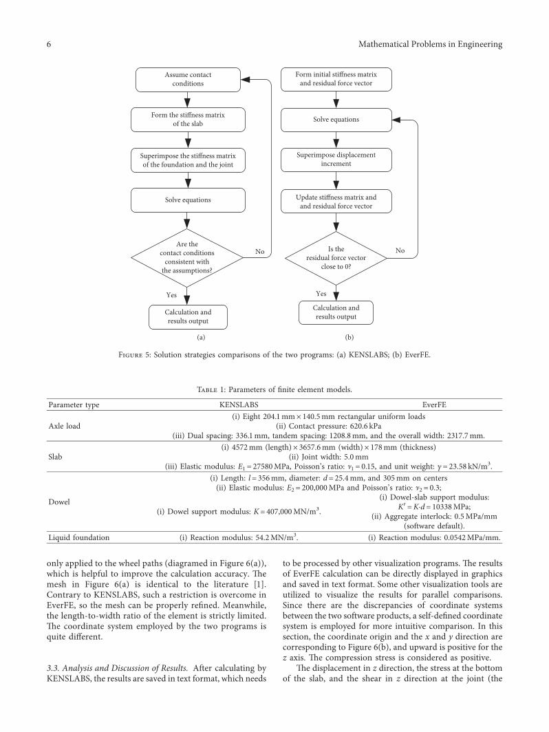
About the contact between slab and base, a bound orunbound two-layer slab can be simulated in KENSLABS,while the lower layer can be regarded as the base layer. Tocapture slab-base shear transfer, EverFE employs 16-nodedzero-thickness quadratic interface elements that aremeshed between the slab and base, as shown in Figure 3.,e sliding of slab and base layer is defined by two con-stitutive parameters: initial distributed stiffness and slip
Mathematical Problems in Engineering 3
displacement, which is similar to an elastic-plastic model.,e slab elements and base elements will not share thenodes in any case, thanks to such a process.
,e consideration approach of KENSLABS and EverFEis quite distinctive for the contact between slab and foun-dation, and KENSLABS can assume that some nodes maynot always in contact with the foundation; namely, gaps mayoccur after being loaded. In the meanwhile, the iterationmethod can be adopted to determine if the slab is in contactwith the foundation. It is also possible to specify the initial
gap values at some nodes, and the program will determinewhether the slab is in contact with the foundation after beingloaded. ,at is to say, the contact condition of slab andfoundation can be defined as full contact, partial contactwithout initial gap, or partial contact with initial gap (liquidfoundation) in KENSLABS. However, only the full contact isassumed in EverFE because it is available for most of thetime.
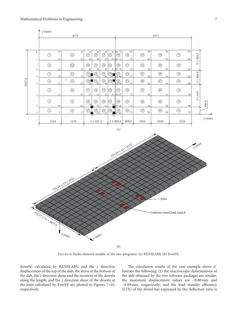
To simulate the interactions between one slab and an-other slab at the joint, dowel or tie bar, and slab, there aregenerally four methods as follows in finite element analysis:(1) a spring element connects two adjacent slabs directly; (2)a beam element directly connects two slabs; (3) a beamelement connects two concrete slabs by spring elements; (4)three-dimensional (3D) solid elements are utilized to de-scribe the contact behaviors. In KENSLABS, a more concisemethod is selected, the first one, as shown in Figure 4(a).Whether there are dowels or ties, interactions should beconverted into a shear spring constant and a moment springconstant at the adjacent nodes by a certain method. InEverFE, the joint simulation is implemented by the secondand third method mentioned above. When the looseness of
Slab
Base
Pairs of nodes vertically constrainedif compression is at interface Horizontal relative
displacement
Interface
Figure 3: Tangential contact between the slab and base in EverFE[36].
2-noded embedded shear beam element 3-noded embedded
flexural element
20-noded solid brick element
8-noded dense liquid elementDriving direction16-noded interface element
Zerothickness
x
zy
Figure 1: Five types of elements embedded in EverFE [36].
LinearBilinearTrilinear
Temperature
Temperature
Thickn
ess
Top
Bottom
Figure 2: Temperature distribution models in EverFE.
4 Mathematical Problems in Engineering
dowel is considered, the second one is activated auto-matically. ,e embedded flexural elements are directlyconnected to the concrete slab; both ends are embedded inthe concrete, and the gaps are symmetrically distributed onboth sides of the joint, as shown in Figure 4(b). It can beseen that the model is nonlinear when the method isadopted. However, if the combined method in Figure 4(c)is activated, that is the third method, the looseness of thedowels cannot be considered. At this time, the model is stilllinear, which is more convenient for calculation. ,ecomputation time is saved, and satisfactory results can alsobe obtained. More details are shown in Figure 4.
2.5. Solution Strategies. KENSLABS follows the generalsolution strategies of conventional analysis (stress anddisplacement): the overall stiffness matrix is obtained bysuperimposing the stiffness matrix of the foundation,joints, and slabs. ,e uniform load is converted into thenodal force, and then the nodal force vector is formed.,erefore, the displacement matrix can be obtained bysolving simultaneous equations, and then the stress andstrain of the node can be solved by the mechanical method.Gauss elimination is employed to solve the problem. Ofcourse, some unusual features can be seen in KENSLABS.Considering when the foundation is liquid foundation, theslab may cause the separation of the slab and foundationwith loading, temperature curling, and self-weight. Or theslabs are not in contact with the foundation on the initialcondition, and the contact behavior may occur afterloading, temperature curling, and self-weight. ,e programintroduces an iterative idea to solve such a situation.Update the assumption of the contact condition in theinitial state over and over again until the assumption isconsistent with the calculation result. Moreover, thestiffness matrix is iterated too in such processing. ,is is ofgreat significance for the analysis of the nonlinearity of thecontact between the slab and foundation.
,e solution strategies of EverFE for general linear andnonlinear analysis resemble to KENSLABS. However,iteration is introduced only in the process of solving si-multaneous equations in EverFE. ,e displacement in-crement matrix is obtained by the residual force vector ineach iteration. ,en, the stiffness matrix updates. ,edisplacement increment is superimposed cyclically, andthe node displacement matrix is obtained when the re-sidual force vector sufficiently is close to zero. Multigrid-preconditioned conjugate gradient (MG-PCG) solver isdeveloped specifically for efficient computation. ,e
stiffness matrix in this iterative process is nonlinear due tothe problem (considering shear transfer between the slaband the base layer, using a dense liquid foundation that istensionless, looseness of the dowels, or selecting a non-linear aggregate interlock model).
,e comparison of the two software packages solutionstrategies is shown in Figure 5.
2.6. Results Output and Visualization. KENSLABS canoutput the calculation results directly in text format tocomputer hard disk, such as temperature curling, z-dis-placement, plane stress, principal stress, shear of dowels,and cracking index. All the input parameters during modelestablishment are also output in the same TXT file to checkthe data correctness. ,e results can only be visualized bysome third-party powerful visualization tools like ORIGIN,SURFER, and ParaView.
EverFE couples a highly interactive graphical userinterface for result visualization written in Tcl/Tk/Tix/vTk. Its strong visualization capabilities and prominentpostprocessing capabilities can display the stresses,displacements, dowel shear, and moment in the graphicalinterface. Critical response values at any point in themodel can be easily retrieved. More importantly, theviews can be curves, cloud map, or contour map on any x,y, or z planes. Additionally, similar to KENSLABS, all themodel parameters and calculation results are saved tocomputer hard disk in text format.
3. Example and Discussion
3.1. Problem Description. Since only the liquid foundationcan be applied in EverFE, appropriate modification of theexample in the literature [1] is made. ,en, a particularexample is designed to illustrate the respective character-istics of two programs. Assume that there is a two-slabsystem on a liquid foundation subjected to a dual-wheeltandem axle load with a total weight of 142.4 kN. ,e frontaxle is applied at the joint with the outside loaded areaadjacent to the pavement edge. Assume that the slab is infull contact with the foundation.
3.2. Finite Element Model. According to the model pa-rameters shown in Table 1, the finite element modelsestablished by two software packages are diagramed inFigure 6. As mentioned above, since the limitation ofpresent dimensions of KENSLABS, the finer meshes are
(a) (b) (c)
Figure 4: Simulation methods of the joint in the two programs [1, 36]: (a) spring element; (b) beam element; (c) spring and beam element.
Mathematical Problems in Engineering 5
only applied to the wheel paths (diagramed in Figure 6(a)),which is helpful to improve the calculation accuracy. ,emesh in Figure 6(a) is identical to the literature [1].Contrary to KENSLABS, such a restriction is overcome inEverFE, so the mesh can be properly refined. Meanwhile,the length-to-width ratio of the element is strictly limited.,e coordinate system employed by the two programs isquite different.
3.3. Analysis and Discussion of Results. After calculating byKENSLABS, the results are saved in text format, which needs
to be processed by other visualization programs. ,e resultsof EverFE calculation can be directly displayed in graphicsand saved in text format. Some other visualization tools areutilized to visualize the results for parallel comparisons.Since there are the discrepancies of coordinate systemsbetween the two software products, a self-defined coordinatesystem is employed for more intuitive comparison. In thissection, the coordinate origin and the x and y direction arecorresponding to Figure 6(b), and upward is positive for thez axis. ,e compression stress is considered as positive.
,e displacement in z direction, the stress at the bottomof the slab, and the shear in z direction at the joint (the
Assume contactconditions
Form the stiffness matrixof the slab
Superimpose the stiffness matrixof the foundation and the joint
Solve equations
Calculation andresults output
Yes
NoAre the
contact conditionsconsistent with
the assumptions?
(a)
Form initial stiffness matrixand residual force vector
Solve equations
Superimpose displacementincrement
Update stiffness matrix andand residual force vector
Is theresidual force vector
close to 0?
Calculation andresults output
Yes
No
(b)
Figure 5: Solution strategies comparisons of the two programs: (a) KENSLABS; (b) EverFE.
Table 1: Parameters of finite element models.
Parameter type KENSLABS EverFE
Axle load(i) Eight 204.1mm× 140.5mm rectangular uniform loads
(ii) Contact pressure: 620.6 kPa(iii) Dual spacing: 336.1mm, tandem spacing: 1208.8mm, and the overall width: 2317.7mm.
Slab(i) 4572mm (length)× 3657.6mm (width)× 178mm (thickness)
(ii) Joint width: 5.0mm(iii) Elastic modulus: E1 � 27580MPa, Poisson’s ratio: ]1 � 0.15, and unit weight: c � 23.58 kN/m3.
Dowel
(i) Length: l� 356mm, diameter: d� 25.4mm, and 305mm on centers(ii) Elastic modulus: E2 � 200,000MPa and Poisson’s ratio: ]2 � 0.3;
(i) Dowel support modulus: K� 407,000MN/m3.
(i) Dowel-slab support modulus:K′�K·d� 10338MPa;
(ii) Aggregate interlock: 0.5MPa/mm(software default).
Liquid foundation (i) Reaction modulus: 54.2MN/m3. (i) Reaction modulus: 0.0542MPa/mm.
6 Mathematical Problems in Engineering
dowels) calculated by KENSLABS, and the z directiondisplacement of the top of the slab, the stress at the bottom ofthe slab, the z direction shear and the moment of the dowelsalong the length, and the z direction shear of the dowels atthe joint calculated by EverFE are plotted in Figures 7–10,respectively.
,e calculation results of the case example above il-lustrate the following: (1) the macroscopic deformations ofthe slab obtained by the two software packages are similar;the maximum displacement values are − 0.80mm and− 0.89mm, respectively; and the load transfer efficiency(LTE) of the dowel bar expressed by the deflection ratio is
14 21
21
20
19
18
17
20
19
18
17
168
7
6
5
4
3
2
1
7
6
5
4
3
2
1
1524
3657
.6
4572y (mm)
4572
1270 3 × 457.2 2 × 406.4
2 ×
635
406.
4
2 ×
406.
42
× 58
4.2
609.6 1016 1016 1524x (mm)
15
14
13
12
11
10
9
8
9
8
10
11
12
13
22
23
24
22
23
24
25
2616
15
27
2825
26
27
28
29
30
31
32
30
31
32
33
34
35
4129
42
43
41
42
43
44
45
46
47
48
44
45
46
47
48
49
49
50
51
52
53
54
55
56
50
51
52
53
54
55
56
57
58
59
60
61
62
57
58
59
60
61
62
63
6463
6465
66
67
68
69
70
65
66
67
68
69
70
71
72
71
72
73
88
87
86
85
84
83
82
81
90
89
91
92
93
94
95
96
97
98
99
100
101
102
103
104
74
75
76
77
73
74
75
76
77
78
79
80
36
33
34
35
36
37
38
39
40
37
38
39
40
(a)
Uniform wheel load, total 8
Joint
351.69 × 13 = 4572
332.57 × 11 = 3657.6
351.69 × 13 = 4572
y (mm)z (mm)
x (mm)
(b)
Figure 6: Finite element models of the two programs: (a) KENSLABS; (b) EverFE.
Mathematical Problems in Engineering 7
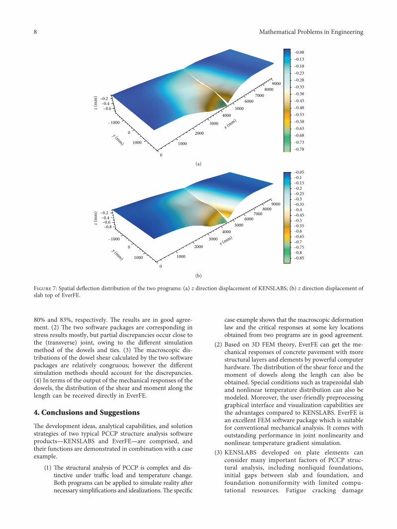
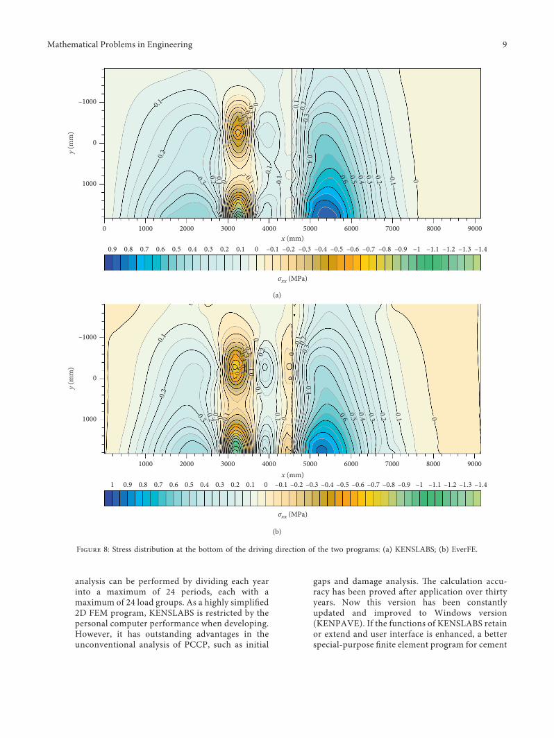
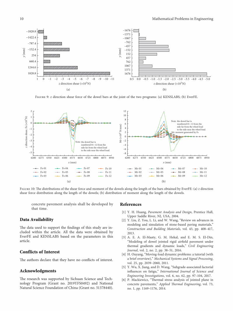
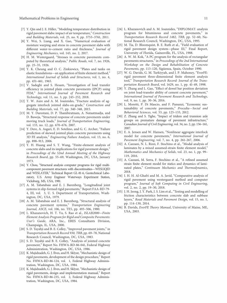
80% and 83%, respectively. ,e results are in good agree-ment. (2) ,e two software packages are corresponding instress results mostly, but partial discrepancies occur close tothe (transverse) joint, owing to the different simulationmethod of the dowels and ties. (3) ,e macroscopic dis-tributions of the dowel shear calculated by the two softwarepackages are relatively congruous; however the differentsimulation methods should account for the discrepancies.(4) In terms of the output of the mechanical responses of thedowels, the distribution of the shear and moment along thelength can be received directly in EverFE.
4. Conclusions and Suggestions
,e development ideas, analytical capabilities, and solutionstrategies of two typical PCCP structure analysis softwareproducts—KENSLABS and EverFE—are comprised, andtheir functions are demonstrated in combination with a caseexample.
(1) ,e structural analysis of PCCP is complex and dis-tinctive under traffic load and temperature change.Both programs can be applied to simulate reality afternecessary simplifications and idealizations.,e specific
case example shows that the macroscopic deformationlaw and the critical responses at some key locationsobtained from two programs are in good agreement.
(2) Based on 3D FEM theory, EverFE can get the me-chanical responses of concrete pavement with morestructural layers and elements by powerful computerhardware. ,e distribution of the shear force and themoment of dowels along the length can also beobtained. Special conditions such as trapezoidal slaband nonlinear temperature distribution can also bemodeled. Moreover, the user-friendly preprocessinggraphical interface and visualization capabilities arethe advantages compared to KENSLABS. EverFE isan excellent FEM software package which is suitablefor conventional mechanical analysis. It comes withoutstanding performance in joint nonlinearity andnonlinear temperature gradient simulation.
(3) KENSLABS developed on plate elements canconsider many important factors of PCCP struc-tural analysis, including nonliquid foundations,initial gaps between slab and foundation, andfoundation nonuniformity with limited compu-tational resources. Fatigue cracking damage
–0.78–0.73–0.68–0.63–0.58–0.53–0.48–0.43–0.38–0.33–0.28–0.23–0.18–0.13–0.08
–0.2–0.4–0.6
–1000
1000 1000
2000
3000
40005000
60007000
80009000
0
0
z (m
m)
y (mm)
x (mm)
(a)
–0.2–0.4–0.6–0.8
–1000
1000 1000
20003000
40005000
60007000
80009000
0
0y (mm)
z (m
m)
x (mm)
–0.85–0.8–0.75–0.7–0.65–0.6–0.55–0.5–0.45–0.4–0.35–0.3–0.25–0.2–0.15–0.1–0.05
(b)
Figure 7: Spatial deflection distribution of the two programs: (a) z direction displacement of KENSLABS; (b) z direction displacement ofslab top of EverFE.
8 Mathematical Problems in Engineering
analysis can be performed by dividing each yearinto a maximum of 24 periods, each with amaximum of 24 load groups. As a highly simplified2D FEM program, KENSLABS is restricted by thepersonal computer performance when developing.However, it has outstanding advantages in theunconventional analysis of PCCP, such as initial
gaps and damage analysis. ,e calculation accu-racy has been proved after application over thirtyyears. Now this version has been constantlyupdated and improved to Windows version(KENPAVE). If the functions of KENSLABS retainor extend and user interface is enhanced, a betterspecial-purpose finite element program for cement
–0.4–0.3
–0.2–0.1
–0.1
0
0
00.1
0.1
0.10.
1
0.1
0.1
0.2
0.2
0.2
0.2
0.3
0.3
0.3
0.4
0.4
0.50.6
–1.4–1.3–1.2–1.1–1–0.9–0.8–0.7–0.6–0.5–0.4–0.3–0.2–0.100.10.20.30.40.50.60.70.80.9
σxx (MPa)
900070003000 4000 5000 60002000 800010000x (mm)
1000
0
–1000
y (m
m)
(a)
σxx (MPa)
–0.6
–0.5–0.4
–0.3–0.2
–0.1
–0.1
0
0
00
00.1
0.1
0.1
0.1
0.1
0.1
0.2
0.20.2
0.2
0.2
0.3
0.3
0.3
0.4
0.4
0.50.6
–1.4–1.3–1.2–1.1–1–0.9–0.8–0.7–0.6–0.5–0.4–0.3–0.2–0.100.10.20.30.40.50.60.70.80.91
900070004000 5000 60003000 800020001000x (mm)
1000
0
–1000
y (m
m)
(b)
Figure 8: Stress distribution at the bottom of the driving direction of the two programs: (a) KENSLABS; (b) EverFE.
Mathematical Problems in Engineering 9
concrete pavement analysis shall be developed bythat time.
Data Availability
,e data used to support the findings of this study are in-cluded within the article. All the data were obtained byEverFE and KENSLABS based on the parameters in thisarticle.
Conflicts of Interest
,e authors declare that they have no conflicts of interest.
Acknowledgments
,e research was supported by Sichuan Science and Tech-nology Program (Grant no. 2019YFS0492) and NationalNatural Science Foundation of China (Grant no. 51378440).
References
[1] Y. H. Huang, Pavement Analysis and Design, Prentice Hall,Upper Saddle River, NJ, USA, 2004.
[2] Y. Liu, Z. You, L. Li, and W. Wang, “Review on advances inmodeling and simulation of stone-based paving materials,”Construction and Building Materials, vol. 43, pp. 408–417,2013.
[3] A. E. A. El-Maaty, G. M. Hekal, and E. M. S. El-Din,“Modeling of dowel jointed rigid airfield pavement underthermal gradients and dynamic loads,” Civil EngineeringJournal, vol. 2, no. 2, pp. 38–51, 2016.
[4] H. Ouyang, “Moving-load dynamic problems: a tutorial (witha brief overview),” Mechanical Systems and Signal Processing,vol. 25, pp. 2039–2060, 2011.
[5] Y. Wu, X. Jiang, and D. Wang, “Subgrade-associated factorialinfluences on fatigu,” International Journal of Science andEngineering Investigations, vol. 6, no. 62, pp. 97–104, 2017.
[6] P. Mackiewicz, “,ermal stress analysis of jointed plane inconcrete pavements,” Applied 7ermal Engineering, vol. 73,no. 1, pp. 1169–1176, 2014.
y (m
m)
0 –1 –2 –3 –4 –5 –6 –7 –8 –9 –10 –111z direction shear (×103N)
1828.8
1244.6
660.4
254
–152.4
–787.4
–1422.4
–1828.8
(a)
y (m
m)
167613711067
762457152
–152–457–762
–1067–1371–1676
0.0 –0.5 –1.0 –1.5 –2.0 –2.5 –3.0 –3.5 –4.0 –4.5 –5.00.5z direction shear (×103N)
(b)
Figure 9: z direction shear force of the dowel bars at the joint of the two programs: (a) KENSLABS; (b) EverFE.
Fs-01Fs-02Fs-03
Fs-07Fs-08Fs-09
Fs-04Fs-05Fs-06
Fs-10Fs-11Fs-12
the dowel bar isnumbered 01~12 from theside far from the wheel loadto the side near the wheel load.
Note:
–5
–4
–3
–2
–1
0
1
2
z dire
ctio
n sh
ear,
Fs (×
103 N
)
4275 4350 4425 4500 4575 4650 4725 4800 4875 49504200
x (mm)
(a)
the dowel bar isnumbered 01~12 from theside far from the wheel loadto the side near the wheel load.
Mr: moment generated by Fs
Note:
Mr-01Mr-02Mr-03
Mr-07Mr-08Mr-09
Mr-04Mr-05Mr-06
Mr-10Mr-11Mr-12
–8–6–4–2
02468
1012
Mr (
×104
N·m
m)
4275 4350 4425 4500 4575 4650 4725 4800 4875 49504200
x (mm)
(b)
Figure 10: ,e distributions of the shear force and moment of the dowels along the length of the bars obtained by EverFE: (a) z directionshear force distribution along the length of the dowels; (b) distribution of moment along the length of the dowels.
10 Mathematical Problems in Engineering
[7] Y. Qin and J. E. Hiller, “Modeling temperature distribution inrigid pavement slabs: impact of air temperature,”Constructionand Building Materials, vol. 25, no. 9, pp. 3753–3761, 2011.
[8] Y. Wei, S. Liang, and X. Gao, “Numerical evaluation ofmoisture warping and stress in concrete pavement slabs withdifferent water-to-cement ratio and thickness,” Journal ofEngineering Mechanics, vol. 143, no. 2, 2017.
[9] H. M. Westergaard, “Stresses in concrete pavements com-puted by theoretical analysis,” Public Roads, vol. 7, no. 1926,pp. 25–35, 1926.
[10] Y. K. Cheung and O. C. Zinkiewicz, “Plates and tanks onelastic foundations—an application of finite elementmethod,”International Journal of Solids and Structures, vol. 1, no. 4,pp. 451–461, 1965.
[11] V. Sadeghi and S. Hesam, “Investigation of load transferefficiency in jointed plain concrete pavements (JPCP) usingFEM,” International Journal of Pavement Research andTechnology, vol. 11, no. 3, pp. 245–252, 2018.
[12] T. W. Aure and A. M. Ioannides, “Fracture analysis of ag-gregate interlock jointed slabs-on-grade,” Construction andBuilding Materials, vol. 77, pp. 340–348, 2015.
[13] M. Y. Darestani, D. P. ,ambiratnam, A. Nataatmadja, andD. Baweja, “Structural response of concrete pavements undermoving truck loads,” Journal of Transportation Engineering,vol. 133, no. 12, pp. 670–676, 2007.
[14] Y. Dere, A. Asgari, E. D. Sotelino, and G. C. Archer, “Failureprediction of skewed jointed plain concrete pavements using3D FE analysis,” Engineering Failure Analysis, vol. 13, no. 6,pp. 898–913, 2006.
[15] Y. H. Huang and S. T. Wang, “Finite-element analysis ofconcrete slabs and its implications for rigid pavement design,”in Proceedings of the 52nd Annual Meeting of the HighwayResearch Board, pp. 55–69, Washington, DC, USA, January1973.
[16] Y. Chou, “Structural analysis computer programs for rigid multi-component pavement structures with discontinuities—WESLIQIDand WESLAYER,” Technical Report GL-81-6, Geotechnical Labo-ratory, U.S. Army Engineer Waterways Experiment Station,Vicksburg, MS, USA, 1981.
[17] A. M. Tabatabaie and E. J. Barenberg, “Longitudinal jointsystems in slip-formed rigid pavements,” Report FAA-RD-79-4, III, vol. 3, U. S. Department of Transportation, Wash-ington, DC, USA, 1979.
[18] A. M. Tabatabaie and E. J. Barenberg, “Structural analysis ofconcrete pavement systems,” Transportation EngineeringJournal, ASCE, vol. 106, no. TE5, pp. 493–506, 1980.
[19] L. Khazanovich, H. T. Yu, S. Rao et al., ISLAB2000—FiniteElement Analysis Program for Rigid and Composite Pavements:User’s Guide, ARA, Inc., ERES Consultants Division,Champaign, IL, USA, 2000.
[20] S. D. Tayabji and B. E. Colley, “Improved pavement joints,” inTransportation Research Record 930, TRB, pp. 69–78, NationalResearch Council, Washington, DC, USA, 1983.
[21] S. D. Tayabji and B. E. Colley, “Analysis of jointed concretepavement,” Report No. FHWA-RD-86-041, Federal HighwayAdministration, Washington, DC, USA, 1986.
[22] K.Majidzadeh, G. J. Ilves, andH. Sklyut, “Mechanistic design ofrigid pavements, development of the design procedure,” ReportNo. FHWA-RD-86-124, vol. 1, Federal Highway Adminis-tration, Washington, DC, USA, 1984.
[23] K.Majidzadeh, G. J. Ilves, andH. Sklyut, “Mechanistic design ofrigid pavements, design and implementation manual,” ReportNo. FHWA-RD-86-235, vol. 2, Federal Highway Adminis-tration, Washington, DC, USA, 1984.
[24] L. Khazanovich and A. M. Ioannides, “DIPLOMAT: analysisprogram for bituminous and concrete pavements,” inTransportation Research Record 1482, TRB, pp. 52–60, Na-tional Research Council, Washington, DC, USA, 1995.
[25] M. Tia, D. Bloomquist, B. E. Ruth et al., “Field evaluation ofrigid pavement design system—phase III,” Final Report,University of Florida, Gainesville, FL, USA, 1988.
[26] A. W. M. Kok, “A PC program for the analysis of rectangularpavements structures,” in Proceedings of the 2nd InternationalWorkshop on the Design and Rehabilitation of ConcretePavements, pp. 113–120, Siguenza, Spain, October 1990.
[27] W. G. Davids, G. M. Turkiyyah, and J. P. Mahoney, “EverFE:rigid pavement three-dimensional finite element analysistool,” Transportation Research Record: Journal of the Trans-portation Research Board, vol. 1629, no. 1, pp. 41–49, 1998.
[28] Y. Zhang and L. Gao, “Effect of dowel bar position deviationon joint load-transfer ability of cement concrete pavement,”International Journal of Pavement Research and Technology,vol. 9, no. 1, pp. 30–36, 2016.
[29] L. Moretti, P. Di Mascio, and F. Panunzi, “Economic sus-tainability of concrete pavements,” Procedia—Social andBehavioral Sciences, vol. 53, pp. 125–133, 2012.
[30] Z. Zhang and S. Tighe, “Impact of tridem and trunnion axlegroups on premature damage of pavement infrastructure,”Canadian Journal of Civil Engineering, vol. 34, no. 2, pp. 156–161,2007.
[31] E. A. Jensen and W. Hansen, “Nonlinear aggregate interlockmodel for concrete pavements,” International Journal ofPavement Engineering, vol. 7, no. 4, pp. 261–267, 2006.
[32] A. Cazzani, N. L. Rizzi, F. Stochino et al., “Modal analysis oflaminates by a mixed assumed-strain finite element model,”Mathematics and Mechanics of Solids, vol. 23, no. 1, pp. 99–119, 2016.
[33] A. Cazzani, M. Serra, F. Stochino et al., “A refined assumedstrain finite element model for statics and dynamics of lami-nated plates,” Continuum Mechanics and 7ermodynamics,2018.
[34] I. H. H. Al-Ghafri and M. A. Javid, “Comparative analysis ofrigid pavement using westergaard method and computerprogram,” Journal of Soft Computing in Civil Engineering,vol. 2, no. 2, pp. 19–30, 2018.
[35] J. H. Jeong, J. Y. Park, J. S. Lim et al., “Testing andmodelling offriction characteristics between concrete slab and subbaselayers,” Road Materials and Pavement Design, vol. 15, no. 1,pp. 114–130, 2014.
[36] B. Davids, EverFE 7eory Manual, University of Maine, ME,USA, 2003.
Mathematical Problems in Engineering 11

Hindawiwww.hindawi.com Volume 2018
MathematicsJournal of
Hindawiwww.hindawi.com Volume 2018
Mathematical Problems in Engineering
Applied MathematicsJournal of
Hindawiwww.hindawi.com Volume 2018
Probability and StatisticsHindawiwww.hindawi.com Volume 2018
Journal of
Hindawiwww.hindawi.com Volume 2018
Mathematical PhysicsAdvances in
Complex AnalysisJournal of
Hindawiwww.hindawi.com Volume 2018
OptimizationJournal of
Hindawiwww.hindawi.com Volume 2018
Hindawiwww.hindawi.com Volume 2018
Engineering Mathematics
International Journal of
Hindawiwww.hindawi.com Volume 2018
Operations ResearchAdvances in
Journal of
Hindawiwww.hindawi.com Volume 2018
Function SpacesAbstract and Applied AnalysisHindawiwww.hindawi.com Volume 2018
International Journal of Mathematics and Mathematical Sciences
Hindawiwww.hindawi.com Volume 2018
Hindawi Publishing Corporation http://www.hindawi.com Volume 2013Hindawiwww.hindawi.com
The Scientific World Journal
Volume 2018
Hindawiwww.hindawi.com Volume 2018Volume 2018
Numerical AnalysisNumerical AnalysisNumerical AnalysisNumerical AnalysisNumerical AnalysisNumerical AnalysisNumerical AnalysisNumerical AnalysisNumerical AnalysisNumerical AnalysisNumerical AnalysisNumerical AnalysisAdvances inAdvances in Discrete Dynamics in
Nature and SocietyHindawiwww.hindawi.com Volume 2018
Hindawiwww.hindawi.com
Di�erential EquationsInternational Journal of
Volume 2018
Hindawiwww.hindawi.com Volume 2018
Decision SciencesAdvances in
Hindawiwww.hindawi.com Volume 2018
AnalysisInternational Journal of
Hindawiwww.hindawi.com Volume 2018
Stochastic AnalysisInternational Journal of
Submit your manuscripts atwww.hindawi.com