Embed Size (px)
Citation preview
Compme
“Upssm
pendiueasure
indu
scalingmall s
Unite
55
um of ees for sction f
und
g enerscale s
S
ed Nations
5, Lodi Esta
energy second furnac
der the
rgy effteel in
Submitted t
s Developm
ate, New De
y efficidary sce (EIF
e proje
ficient ndustr
to
ment Progra
elhi - 110 0
ient testeel elF) sect
ect
produry in In
amme
03
echnollectrictor
uctionndia”
ogy c
n in
THE TEAM Overall Assignment Guidance
Ministry of Steel
Mr. A.C.R. Das
Assignment Coordination
United Nations Development Programme
Dr. S.N. Srinivas
Ms. Manisha Sanghani
Project Management Unit
Mr. S. Sathis Kumar
Mr. Arindam Mukherjee
Assignment Execution Team
PricewaterhouseCoopers Private Limited
Mr. Amit Kumar
Mr. Rajeev Ralhan
Mr. Manoj Kumar Bansal
Mr. Pradeep Singhvi
Mr. Arvind Kumar Gautam
Sector Experts
Mr. A.N. Jha
Mr. Shyam Kulkarni
Table of Contents
Table of contents
Acknowledgement 6
1. About the induction furnace sector 7
2. Background of the project 8
2.1. Project approach 8
2.2. Project analysis 8
3. Compendium of energy efficient technology measures for electric induction furnace (EIF) sector 11
3.1. Installation of shredding machine and scrap charging through bucket or vibro feeder 12
3.2. Replacement of coil cradle of old furnace 15
3.3. Installation of CCM for billet making 18
3.4. Installation of sintering panel for sintering heat 21
3.5. Scrap preheating 23
3.6. Ladle preheating 26
3.7. Avoid superheating of the metals 29
3.8. Avoid overfilling (metal above the coil level) of furnace during melting 30
3.9. Energy-efficient pumps 33
3.10. FRP blades in cooling tower 36
3.11. Variable Frequency Drive (VFD) on air compressor 37
4. Annexure A: List of Suppliers and/or Manufactures 39
Table of Contents
List of Tables
Table 1: List of possible EE technology packages/options ...................................................................................... 11 Table 2: Shredding machine - Salient features, investment and benefits .............................................................. 12 Table 3: Sample calculation for shredding machine in scrap based unit (8 tonnes/heat) .................................... 13 Table 4: Sample calculation for shredding machine in DRI based unit (12 tonnes/heat) ..................................... 14 Table 5: Replacement of coil cradle - Salient features, investment and benefits ................................................... 15 Table 6: Sample calculation for replacement of coil cradle in scrap based unit (8 tonnes/heat).......................... 16 Table 7: Sample calculation for replacement of coil cradle in DRI based unit (12 tonnes/heat) .......................... 16 Table 8: Replacement of use of moulds with CCM ................................................................................................. 19 Table 9: Sample calculation for installation of CCM for billet making (8 tonnes/heat) ........................................ 19 Table 10: Installation of sintering panel for sintering heat .................................................................................... 21 Table 11: Sample calculation for installation of sintering panel for sintering heat in scrap based unit (8 tonnes/heat) ............................................................................................................................................................ 22 Table 12: Sample calculation for installation of sintering panel for sintering heat in DRI based unit (12 tonnes/heat) ............................................................................................................................................................ 22 Table 13: Scrap preheating - Salient features, investment and benefits ................................................................ 24 Table 14: Sample calculation for scrap preheating using furnace oil in scrap based unit (8 tonnes/heat) ........... 24 Table 15: Sample calculation for scrap preheating using furnace oil in DRI based unit (12 tonnes per heat) ...... 25 Table 16: Ladle preheating - Salient features, investment and benefits ................................................................ 26 Table 17: Sample calculation for ladle preheating using LDO in scrap based unit (8 tonnes/heat) ..................... 27 Table 18: Sample calculation for ladle preheating using LDO in DRI based unit (12 tonnes/heat) ..................... 28 Table 19: Sample calculation for avoiding excess super heating of metal in the furnace (mostly in units with CCM) (12 tonnes/heat) ............................................................................................................................................ 29 Table 20: Sample calculation for avoiding overfilling of furnace during meting case scrap based unit (8 tonnes/heat) ............................................................................................................................................................ 30 Table 21: Sample calculation for avoiding overfilling of furnace during meting case DRI based unit (12 tonnes/heat) ............................................................................................................................................................ 31 Table 22: Energy-efficient pump: Salient features, investment and benefits ........................................................ 33 Table 23: Sample calculation for energy-efficient pump (8 tonne/heat) ............................................................... 33 Table 24: Sample calculation for energy-efficient pump (12 tonne/heat) ............................................................. 34 Table 25: FRP blades: - Salient features, investment and benefits ........................................................................ 36 Table 26: Sample calculation for replacement of metallic/aluminium blades of cooling towers with FRP blades .................................................................................................................................................................................. 36 Table 27: VFD on air compressor - Salient features, investment and benefits ...................................................... 37 Table 28: Sample calculation for installation of variable frequency drive ............................................................. 37
List of Figures Figure 1: Shredding machine ................................................................................................................................... 12 Figure 2: Coil cradle assembly ................................................................................................................................. 15 Figure 3: Mould filling using runner and gate system ............................................................................................ 18 Figure 4: Runner and gate system .......................................................................................................................... 18 Figure 5: CCM operation ......................................................................................................................................... 18 Figure 6: Sintering panel ......................................................................................................................................... 21 Figure 7: Scrap preheating system .......................................................................................................................... 23 Figure 8: Ladle preheating system .......................................................................................................................... 26 Figure 9: Ladle transfer for CCM operation ............................................................................................................ 29 Figure 10: Overfilling of furnace ............................................................................................................................. 30
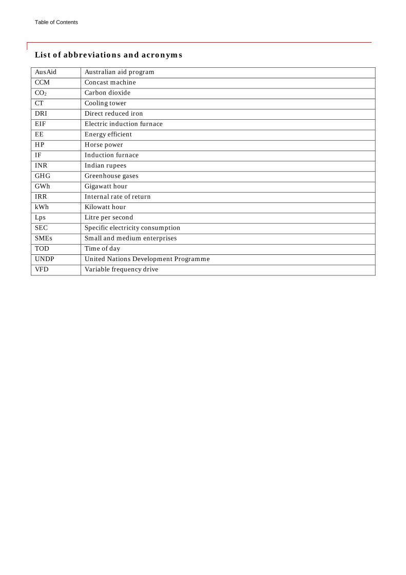
Table of Contents
List of abbreviations and acronyms
AusAid Australian aid program CCM Concast machine CO2 Carbon dioxide CT Cooling tower DRI Direct reduced iron EIF Electric induction furnace EE Energy efficient HP Horse power IF Induction furnace INR Indian rupees GHG Greenhouse gases GWh Gigawatt hour IRR Internal rate of return kWh Kilowatt hour Lps Litre per second SEC Specific electricity consumption SMEs Small and medium enterprises TOD Time of day UNDP United Nations Development Programme VFD Variable frequency drive

Acknowledgement
Acknowledgement PricewaterhouseCoopers (PwC) would like to gratefully acknowledge UNDP, for its valuable initiative in the execution of the project, entitled “Upscaling energy efficient production in small scale steel industry in India”. The team at PwC is grateful to UNDP for associating PwC in this important assignment.
PwC wishes to express our appreciation for the support and guidance extended to us by the Ministry of Steel (MoS). The team is also thankful to Shri A.C.R. Das, Advisor, Ministry of Steel (Govt. of India) for his valuable guidance during the execution of this assignment.
We would like to specially acknowledge the valuable inputs and guidance provided by Dr. S.N. Srinivas, Programme Officer and Ms. Manisha Sanghani, Programme Associate, UNDP, during the execution of the assignment. Thanks are due to the entire team of Project Management Unit, UNDP (Steel Upscale Project). PwC would especially acknowledge the contribution of Shri S Sathis Kumar, Project Manager (Technical), UNDP (Steel Upscale Project) for his excellent coordination provided during the entire duration of the assignment. This compendium would not have been possible with the support of the participating induction furnace units. We wish to thank the management and staff of all participating induction furnace units for their time, commitment and co-operation extended to the energy audit team during their filed visits and studies.
A
1Tcw2r
If
C
Tcf
T
1
About the induct
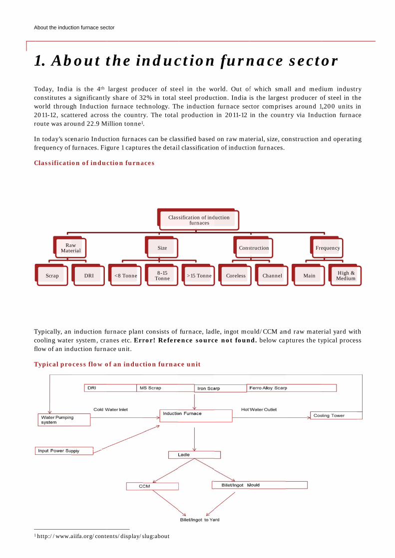
1. AbToday, Indiaconstitutes aworld throug2011-12, scatroute was aro
In today’s scefrequency of
Classificati
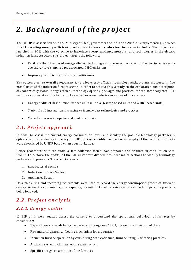
Typically, ancooling waterflow of an ind
Typical pro
http://www.a
RaMate
Scrap
tion furnace sec
bout ta is the 4th a significantlygh Inductionttered acrossound 22.9 M
enario Induc furnaces. Fig
ion of induc
n induction fur system, craduction furn
ocess flow o
aiifa.org/conte
aw erial
DRI
ctor
the inlargest prody share of 3
n furnace tecs the countr
Million tonne1
ction furnacegure 1 captur
ction furna
urnace plantanes etc. Errace unit.
of an induc
ents/display/s
<8 Tonne
nducducer of ste2% in total chnology. Thry. The total .
es can be clasres the detail
aces
t consists of ror! Refere
tion furnac
slug:about
Class
Size
8-15 Tonne
ctioneel in the wo
steel produche induction production
ssified basedl classificatio
furnace, ladence sourc
ce unit
sification of indfurnaces
>15 Tonne
n furnorld. Out ofction. India in furnace sec in 2011-12
d on raw maton of inductio
dle, ingot moce not foun
duction
Cons
Coreless
nace f which smais the largesctor comprisin the count
terial, size, coon furnaces.
ould/CCM annd. below cap
struction
Channel
sectall and medst producer oses around 1try via Indu
onstruction a
nd raw mateptures the ty
Fre
Main
tor dium industrof steel in th1,200 units iuction furnac
and operatin
rial yard witypical proces
equency
High & Medium
ry he in ce
ng
th ss
Background of the project
2. Background of the project The UNDP in association with the Ministry of Steel, government of India and AusAid is implementing a project titled Upscaling energy-efficient production in small scale steel industry in India. The project was launched in 2013 with the objective to introduce energy efficiency measures and technologies in the electric induction furnace sector. This project targets the following:
• Facilitate the diffusion of energy-efficient technologies in the secondary steel EIF sector to reduce end-use energy levels and reduce associated GHG emissions
• Improve productivity and cost competitiveness
The outcome of the overall programme is to pilot energy-efficient technology packages and measures in five model units of the induction furnace sector. In order to achieve this, a study on the exploration and description of economically viable energy-efficient technology options, packages and practices for the secondary steel EIF sector was undertaken. The following key activities were undertaken as part of this exercise.
• Energy audits of 10 induction furnace units in India (6 scrap based units and 4 DRI based units)
• National and international scouting to identify best technologies and practices
• Consultation workshops for stakeholders inputs
2.1. Project approach In order to assess the current energy consumption levels and identify the possible technology packages & options to improve energy efficiency; 10 EIF units were audited across the geography of the country. EIF units were shortlisted by UNDP based on an open invitation.
Before proceeding with the audit, a data collection format was prepared and finalized in consultation with UNDP. To perform the audits, all the EIF units were divided into three major sections to identify technology packages and practices. These sections were:
1. Raw Material Section
2. Induction Furnace Section
3. Auxiliaries Section
Data measuring and recording instruments were used to record the energy consumption profile of different energy consuming equipments, power quality, operation of cooling water systems and other operating practices being followed.
2.2. Project analysis 2.2.1. Energy audits
10 EIF units were audited across the country to understand the operational behaviour of furnaces by considering:
• Types of raw materials being used – scrap, sponge iron/ DRI, pig iron, combination of these
• Raw material charging/ feeding mechanism for the furnace
• Induction furnace operation by considering heat/cycle time, furnace lining & sintering practices
• Auxiliary system including cooling water system
• Specific energy consumption of the furnaces
Background of the project
2.2.2. Scouting of technologies
The scouting of appropriate energy efficiency interventions available nationally and internationally in the EIF sector was done through literature review, discussions with technology providers, subject matter experts and unit owners, industry associations. A detailed analysis of the best available technologies nationally and internationally was carried out and the technologies appropriate to Indian conditions were identified. Some case studies were also prepared based on the information gathered during the discussions with sector experts.
Some major technology packages and energy efficient pratices identified during scouting and also identified during the energy audits were:
S. No. EE Technology packages EE practices/options 1 Installation of shredding machine and shredded
scrap charging through bucket or vibro-feeder Use of Neutral Lining
2 Replacement of coil cradle of old furnace Avoid superheating of molten metal 3
Installation of CCM for billet making Overfilling (metal above the coil level) of furnace during the melting
4 Sintering panel for sintering heat Installation of VFD on the air compressor 5 Scrap preheating Installation of EE pumps 6 Ladle preheating FRP blades in cooling tower
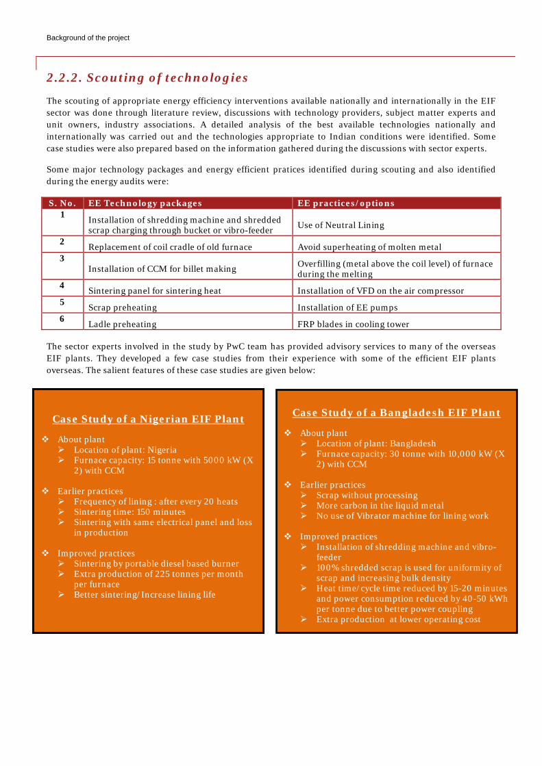
The sector experts involved in the study by PwC team has provided advisory services to many of the overseas EIF plants. They developed a few case studies from their experience with some of the efficient EIF plants overseas. The salient features of these case studies are given below:
Case Study of a Bangladesh EIF Plant
About plant Location of plant: Bangladesh Furnace capacity: 30 tonne with 10,000 kW (X
2) with CCM
Earlier practices Scrap without processing More carbon in the liquid metal No use of Vibrator machine for lining work
Improved practices
Installation of shredding machine and vibro-feeder
100% shredded scrap is used for uniformity of scrap and increasing bulk density
Heat time/cycle time reduced by 15-20 minutes and power consumption reduced by 40-50 kWh per tonne due to better power coupling
Extra production at lower operating cost
Case Study of a Nigerian EIF Plant
About plant Location of plant: Nigeria Furnace capacity: 15 tonne with 5000 kW (X
2) with CCM
Earlier practices Frequency of lining : after every 20 heats Sintering time: 150 minutes Sintering with same electrical panel and loss
in production
Improved practices Sintering by portable diesel based burner Extra production of 225 tonnes per month
per furnace Better sintering/Increase lining life
Background of the project
2.2.3. Consultation meeting
Two consultation meetings were organized to share the findings of the study and acknowledge feedback of different stakeholders on the identified options. Major highlights of the stakeholder meetings were:
First stakeholder consultation meeting - Explore the different technology options
First stakeholder consultation meeting was held on 21st August 2014, at Hotel Imperial, New Delhi. The meeting had participants from key stakeholder groups including Induction Furnace Association members, Industry bodies, Induction Furnace and equipment suppliers, Consultants as well as Induction Furnace unit owners. Total 35 participants attended the stakeholder meeting. The objective of first stakeholder consultation meeting was to present the findings of the studies conducted by PwC and explore different EE technology options for EIF. Different technology providers also shared the technologies being provided by them to improve energy efficiency in the EIF units. All the stakeholders agreed to the findings of PwC and appreciated the idea and initiative of UNDP to assess the energy efficiency potential and develop some model units in this sector.
Second stakeholder consultation meeting - Finalisation of the identified technologies options
Second stakeholder consultation meeting was held on 9th October 2014, at Hotel Le Meridien, New Delhi. The meeting got participation from key stakeholders including Induction Furnace Association members, Industry bodies, Induction Furnace and equipment supplier, Consultants as well as Induction Furnace unit owners. Total 38 participants attended the stakeholder meeting. The objective of second stakeholder consultation meeting was to finalise the different EE technology options for EIF. Second consultation meeting was also intended to acknowledge the feedback from different stakeholders on identified technology packages/options for EIF. All the stakeholders appreciated the findings and analysis carried out in the study and suggested next action to plan the model EIF units in the country.
Draft compendium was shared with all the stakeholders to request their feedback on the identified EE technology options. A week’s time was provided to the stakeholders to give feedback on these technology options. Based on the comments received in the feedback, compendium was modified and finalized.
Compendium of energy efficient technology measures for electric induction furnace (EIF) sector
3. Compendium of energy efficient technology measures for electric induction furnace (EIF) sector
Based on the complete analysis after energy audits, scouting and consultation meetings, following EE technology options and packages were recommended. Stakeholders’ response was also taken up and the compendium was finalized. The following technology packages and options are proposed for both scrap and DRI based units.
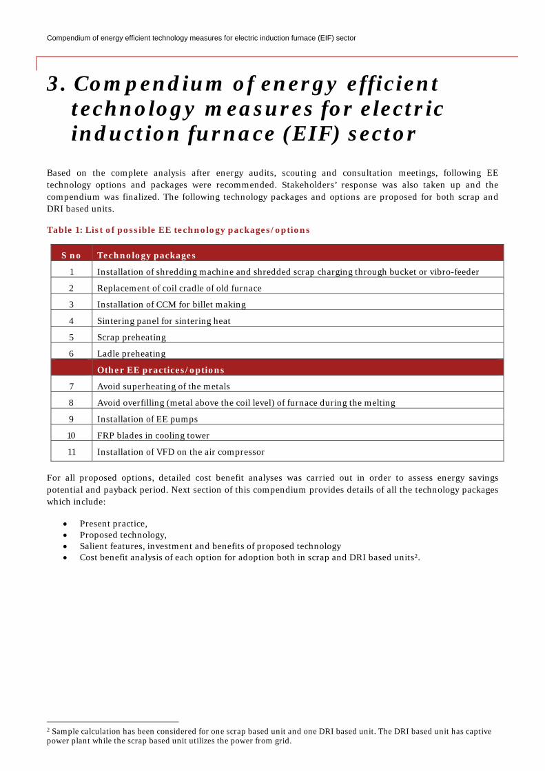
Table 1: List of possible EE technology packages/options
S no Technology packages
1 Installation of shredding machine and shredded scrap charging through bucket or vibro-feeder
2 Replacement of coil cradle of old furnace
3 Installation of CCM for billet making
4 Sintering panel for sintering heat
5 Scrap preheating
6 Ladle preheating
Other EE practices/options
7 Avoid superheating of the metals
8 Avoid overfilling (metal above the coil level) of furnace during the melting
9 Installation of EE pumps
10 FRP blades in cooling tower
11 Installation of VFD on the air compressor
For all proposed options, detailed cost benefit analyses was carried out in order to assess energy savings potential and payback period. Next section of this compendium provides details of all the technology packages which include:
• Present practice, • Proposed technology, • Salient features, investment and benefits of proposed technology • Cost benefit analysis of each option for adoption both in scrap and DRI based units2.
2 Sample calculation has been considered for one scrap based unit and one DRI based unit. The DRI based unit has captive power plant while the scrap based unit utilizes the power from grid.
Compendium of energy efficient technology measures for electric induction furnace (EIF) sector
3.1. Installation of shredding machine and scrap charging through bucket or vibro feeder
3.1.1. Present practice
Scrap is the major raw material in induction furnace units across India especially in northern and western India. In these areas the scrap quantities being used normally are more than 70%. The present practice suggests that a majority of induction furnace unit feed unprocessed scrap. The unprocessed or non-shredded scrap is fed with the charge mix either by magnet or through a manual charging mechanism. Due to this charging practice, the bulk density of the scrap charge is low which results in air pockets (voids) between the scrap pieces that subsequently leads to low power density, ultimately increasing the heat/cycle time. Best charging practices such as bucket charging or charging through vibro-feeder is also not possible for non-shredded scrap, leading to the furnace operating at low efficiency.
3.1.2. Proposed technology
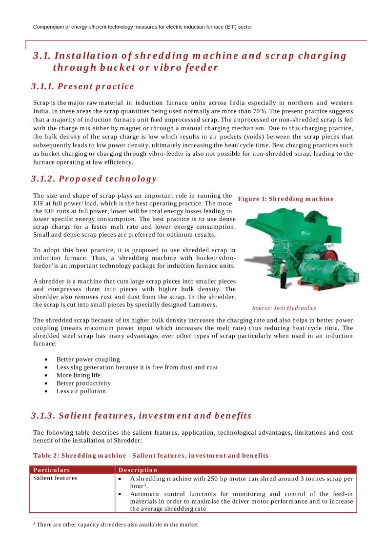
The size and shape of scrap plays an important role in running the EIF at full power/load, which is the best operating practice. The more the EIF runs at full power, lower will be total energy losses leading to lower specific energy consumption. The best practice is to use dense scrap charge for a faster melt rate and lower energy consumption. Small and dense scrap pieces are preferred for optimum results. To adopt this best practice, it is proposed to use shredded scrap in induction furnace. Thus, a ‘shredding machine with bucket/vibro-feeder’ is an important technology package for induction furnace units. A shredder is a machine that cuts large scrap pieces into smaller pieces and compresses them into pieces with higher bulk density. The shredder also removes rust and dust from the scrap. In the shredder, the scrap is cut into small pieces by specially designed hammers. The shredded scrap because of its higher bulk density increases the charging rate and also helps in better power coupling (means maximum power input which increases the melt rate) thus reducing heat/cycle time. The shredded steel scrap has many advantages over other types of scrap particularly when used in an induction furnace:
• Better power coupling • Less slag generation because it is free from dust and rust • More lining life • Better productivity • Less air pollution
3.1.3. Salient features, investment and benefits
The following table describes the salient features, application, technological advantages, limitations and cost benefit of the installation of Shredder: Table 2: Shredding machine - Salient features, investment and benefits
Particulars Description Salient features • A shredding machine with 250 hp motor can shred around 3 tonnes scrap per
hour3. • Automatic control functions for monitoring and control of the feed-in
materials in order to maximise the driver motor performance and to increase the average shredding rate
3 There are other capacity shredders also available in the market
Figure 1: Shredding machine
Source: Jain Hydraulics
Compendium of energy efficient technology measures for electric induction furnace (EIF) sector
• Reliable operation and ease of maintenance of the shredding plants at a lower processing cost-per-tonne of scrap
Application • A shredding machine provides uniformly sized dust-free scrap with good bulk density.
Technological limitation • As such, there is no technological limitation, but the apprehension with the shredding machine is its applicability only for light commercial scrap. Supply and availability of light commercial scrap is a concern in India.
Estimated investment • INR 75 lakh (approximate cost for shredder machine for 250 hp motor) and INR 15.50 lakh for bucket and vibro feeder
Estimated implementation period
• 15 to 20 days
Expected benefits • Electricity consumption can be reduced by 5 to 10% per heat. Estimated payback on investment
• 12 months for scrap based unit as they are dependent on grid power which is costly
• 23 months for DRI based unit as they normally use their captive power which is cheaper in comparison to grid power
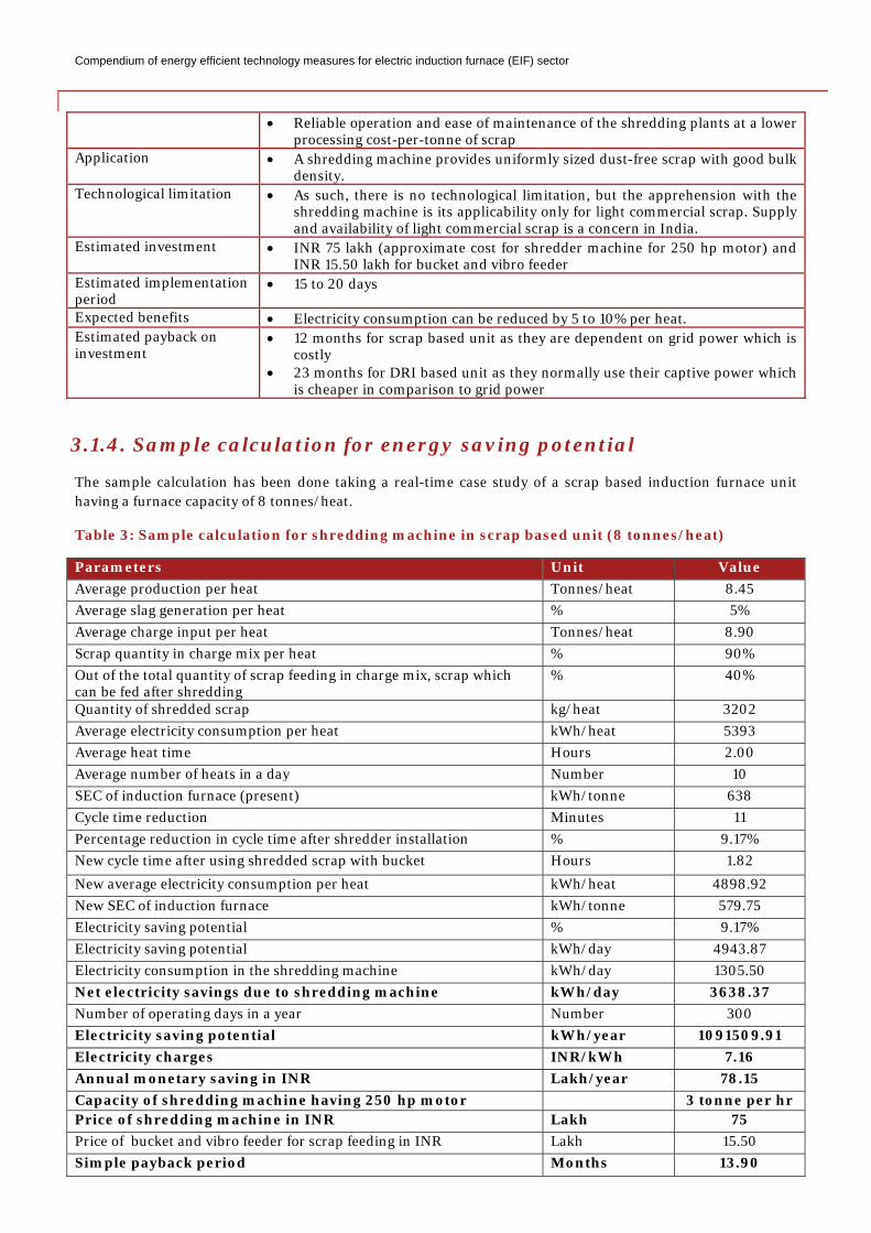
3.1.4. Sample calculation for energy saving potential
The sample calculation has been done taking a real-time case study of a scrap based induction furnace unit having a furnace capacity of 8 tonnes/heat.
Table 3: Sample calculation for shredding machine in scrap based unit (8 tonnes/heat)
Parameters Unit Value Average production per heat Tonnes/heat 8.45 Average slag generation per heat % 5% Average charge input per heat Tonnes/heat 8.90 Scrap quantity in charge mix per heat % 90% Out of the total quantity of scrap feeding in charge mix, scrap which can be fed after shredding
% 40%
Quantity of shredded scrap kg/heat 3202 Average electricity consumption per heat kWh/heat 5393 Average heat time Hours 2.00 Average number of heats in a day Number 10 SEC of induction furnace (present) kWh/tonne 638 Cycle time reduction Minutes 11 Percentage reduction in cycle time after shredder installation % 9.17% New cycle time after using shredded scrap with bucket Hours 1.82
New average electricity consumption per heat kWh/heat 4898.92 New SEC of induction furnace kWh/tonne 579.75 Electricity saving potential % 9.17% Electricity saving potential kWh/day 4943.87 Electricity consumption in the shredding machine kWh/day 1305.50 Net electricity savings due to shredding machine kWh/day 3638.37 Number of operating days in a year Number 300 Electricity saving potential kWh/year 1091509.91 Electricity charges INR/kWh 7.16 Annual monetary saving in INR Lakh/year 78.15 Capacity of shredding machine having 250 hp motor 3 tonne per hr Price of shredding machine in INR Lakh 75 Price of bucket and vibro feeder for scrap feeding in INR Lakh 15.50 Simple payback period Months 13.90
Compendium of energy efficient technology measures for electric induction furnace (EIF) sector
GHG reduction potential4 tCO2/year 851.38
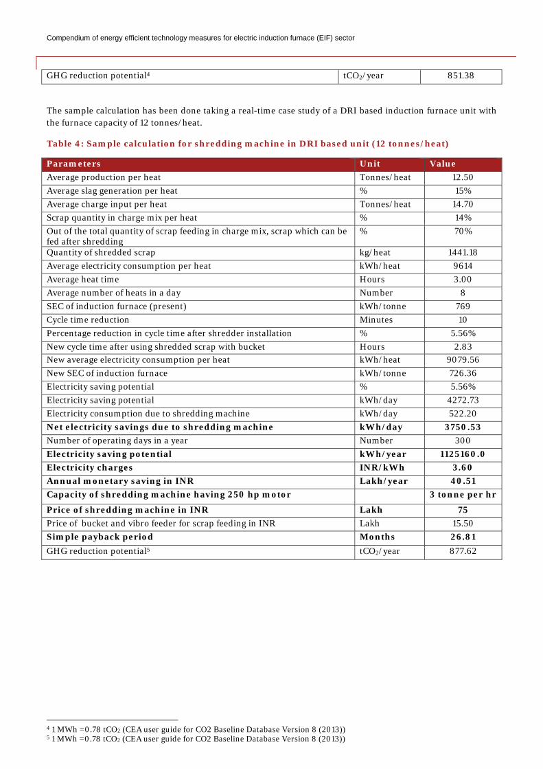
The sample calculation has been done taking a real-time case study of a DRI based induction furnace unit with the furnace capacity of 12 tonnes/heat.
Table 4: Sample calculation for shredding machine in DRI based unit (12 tonnes/heat)
Parameters Unit Value Average production per heat Tonnes/heat 12.50 Average slag generation per heat % 15% Average charge input per heat Tonnes/heat 14.70 Scrap quantity in charge mix per heat % 14% Out of the total quantity of scrap feeding in charge mix, scrap which can be fed after shredding
% 70%
Quantity of shredded scrap kg/heat 1441.18 Average electricity consumption per heat kWh/heat 9614 Average heat time Hours 3.00 Average number of heats in a day Number 8 SEC of induction furnace (present) kWh/tonne 769 Cycle time reduction Minutes 10 Percentage reduction in cycle time after shredder installation % 5.56% New cycle time after using shredded scrap with bucket Hours 2.83 New average electricity consumption per heat kWh/heat 9079.56 New SEC of induction furnace kWh/tonne 726.36 Electricity saving potential % 5.56% Electricity saving potential kWh/day 4272.73 Electricity consumption due to shredding machine kWh/day 522.20 Net electricity savings due to shredding machine kWh/day 3750.53 Number of operating days in a year Number 300 Electricity saving potential kWh/year 1125160.0 Electricity charges INR/kWh 3.60 Annual monetary saving in INR Lakh/year 40.51 Capacity of shredding machine having 250 hp motor 3 tonne per hr
Price of shredding machine in INR Lakh 75 Price of bucket and vibro feeder for scrap feeding in INR Lakh 15.50 Simple payback period Months 26.81 GHG reduction potential5 tCO2/year 877.62
4 1 MWh =0.78 tCO2 (CEA user guide for CO2 Baseline Database Version 8 (2013)) 5 1 MWh =0.78 tCO2 (CEA user guide for CO2 Baseline Database Version 8 (2013))
C
3
3
Iotd•••
3
Riddampicpiecurr
Tei
3
Tb T
PS
A
TE
EpE
Compendium of
3.2. Rep
3.2.1. Pr
In some induof coil cradlethe efficiencydue to the fol• Non-unif• Non-effic• Low curr
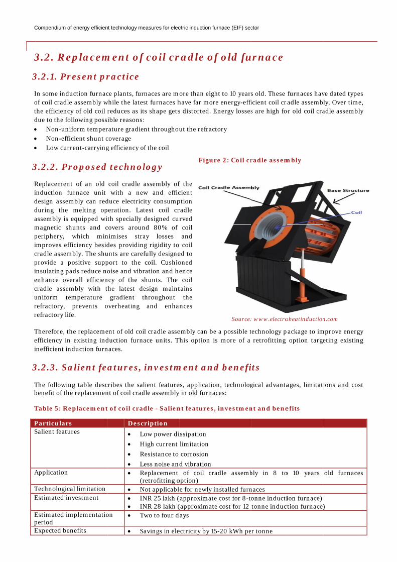
3.2.2. Pr
Replacementnduction fu
design assemduring the assembly is emagnetic shperiphery, mproves effi
cradle assemprovide a ponsulating pa
enhance ovecradle assemuniform temrefractory, refractory life
Therefore, thefficiency in nefficient ind
3.2.3. Sa
The followinbenefit of the
Table 5: Re
ParticularsSalient featur
Application
TechnologicaEstimated inv
Estimated imperiod Expected ben
f energy efficien
placem
resent pr
uction furnace assembly wy of old coil rllowing possiform tempercient shunt crent-carrying
roposed
t of an old urnace unit mbly can red
melting opequipped wit
hunts and cwhich min
ficiency besidmbly. The shu
ositive suppads reduce noerall efficienmbly with tmperature prevents oe.
he replaceme existing indduction furn
alient fea
ng table desce replacemen
eplacement
s res
al limitation vestment
mplementatio
nefits
nt technology me
ment of
ractice
ce plants, furwhile the lates
reduces as itible reasons:
rature gradiecoverage g efficiency o
technol
coil cradle with a new
duce electriciperation. Lat
th specially covers arounnimises strades providinunts are carefport to the oise and vibr
ncy of the she latest degradient t
overheating
ent of old coiduction furnnaces.
atures,
cribes the salnt of coil crad
t of coil cra
Desc• L• H• R• L• R
(r • N
• IN• IN
on • T
• S
easures for elec
f coil cr
rnaces are most furnaces hts shape gets:
ent throughou
of the coil
logy
assembly ofw and efficity consumptest coil crdesigned cur
nd 80% of ay losses g rigidity to fully designecoil. Cushio
ration and heshunts. The esign maintthroughout
and enhan
il cradle asseace units. Th
investm
lient featuredle assembly
dle - Salien
cription Low power diHigh current Resistance to Less noise andReplacement retrofitting o
Not applicablNR 25 lakh (NR 28 lakh (
Two to four d
avings in ele
ctric induction fu
radle of
ore than eighhave far mors distorted. E
ut the refract
f the cient ption radle rved coil and
coil ed to oned ence coil tains
the nces
embly can beThis option is
ment and
es, applicatioy in old furna
nt features,
issipation limitation corrosion d vibration of coil cra
option) e for newly i
(approximate(approximate
days
ectricity by 15
Figur
urnace (EIF) sec
f old fu
ht to 10 yearsre energy-effiEnergy losses
tory
e a possible ts more of a
d benefi
on, technologaces:
, investmen
adle assemb
nstalled furne cost for 8-te cost for 12-
5-20 kWh pe
Source:
re 2: Coil cr
ctor
urnace
s old. These ficient coil cras are high fo
technology p retrofitting
its
gical advanta
nt and bene
bly in 8 to
naces onne inducti
-tonne induct
er tonne
: www.electro
radle assem
furnaces havradle assembor old coil cra
package to im option targ
ages, limitat
efits
o 10 years
ion furnace) ction furnace
oheatinduction
mbly
ve dated typebly. Over timeadle assembl
mprove energeting existin
ions and cos
old furnace
)
n.com
es e, ly
gy ng
st
es
Compendium of energy efficient technology measures for electric induction furnace (EIF) sector
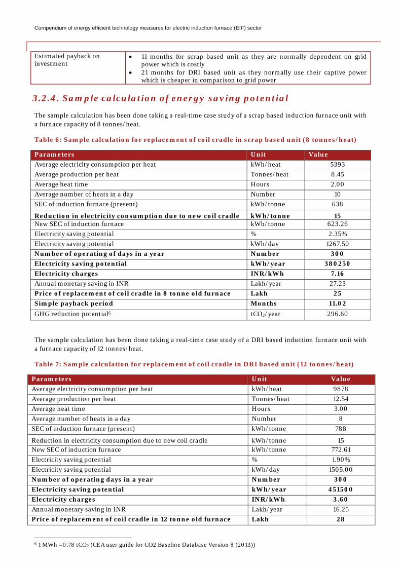
Estimated payback on investment
• 11 months for scrap based unit as they are normally dependent on grid power which is costly
• 21 months for DRI based unit as they normally use their captive power which is cheaper in comparison to grid power
3.2.4. Sample calculation of energy saving potential
The sample calculation has been done taking a real-time case study of a scrap based induction furnace unit with a furnace capacity of 8 tonnes/heat.
Table 6: Sample calculation for replacement of coil cradle in scrap based unit (8 tonnes/heat)
Parameters Unit Value Average electricity consumption per heat kWh/heat 5393 Average production per heat Tonnes/heat 8.45 Average heat time Hours 2.00 Average number of heats in a day Number 10 SEC of induction furnace (present) kWh/tonne 638
Reduction in electricity consumption due to new coil cradle kWh/tonne 15 New SEC of induction furnace kWh/tonne 623.26 Electricity saving potential % 2.35% Electricity saving potential kWh/day 1267.50 Number of operating of days in a year Number 300 Electricity saving potential kWh/year 380250 Electricity charges INR/kWh 7.16 Annual monetary saving in INR Lakh/year 27.23 Price of replacement of coil cradle in 8 tonne old furnace Lakh 25 Simple payback period Months 11.02 GHG reduction potential6 tCO2/year 296.60
The sample calculation has been done taking a real-time case study of a DRI based induction furnace unit with a furnace capacity of 12 tonnes/heat.
Table 7: Sample calculation for replacement of coil cradle in DRI based unit (12 tonnes/heat)
Parameters Unit Value Average electricity consumption per heat kWh/heat 9878 Average production per heat Tonnes/heat 12.54 Average heat time Hours 3.00 Average number of heats in a day Number 8 SEC of induction furnace (present) kWh/tonne 788
Reduction in electricity consumption due to new coil cradle kWh/tonne 15 New SEC of induction furnace kWh/tonne 772.61 Electricity saving potential % 1.90% Electricity saving potential kWh/day 1505.00 Number of operating days in a year Number 300 Electricity saving potential kWh/year 451500 Electricity charges INR/kWh 3.60 Annual monetary saving in INR Lakh/year 16.25 Price of replacement of coil cradle in 12 tonne old furnace Lakh 28
6 1 MWh =0.78 tCO2 (CEA user guide for CO2 Baseline Database Version 8 (2013))
Compendium of energy efficient technology measures for electric induction furnace (EIF) sector
Simple payback period Months 20.67 GHG reduction potential7 tCO2/year 352.17
7 1 MWh =0.78 tCO2 (CEA user guide for CO2 Baseline Database Version 8 (2013))
Compendium of energy efficient technology measures for electric induction furnace (EIF) sector
3.3. Installation of CCM for billet making
3.3.1. Present practice
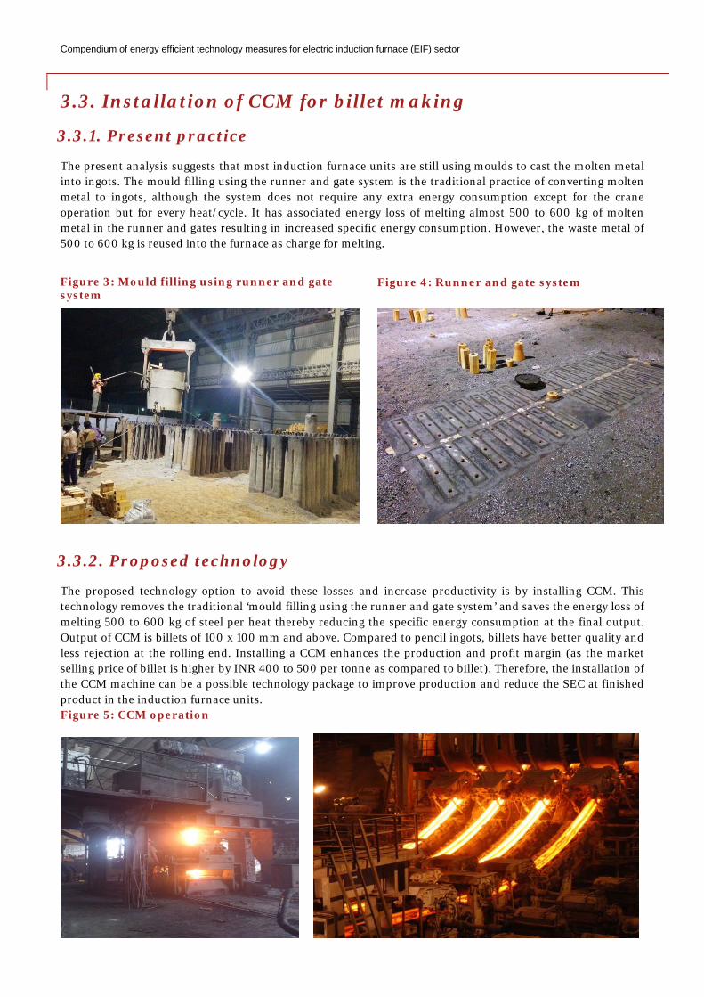
The present analysis suggests that most induction furnace units are still using moulds to cast the molten metal into ingots. The mould filling using the runner and gate system is the traditional practice of converting molten metal to ingots, although the system does not require any extra energy consumption except for the crane operation but for every heat/cycle. It has associated energy loss of melting almost 500 to 600 kg of molten metal in the runner and gates resulting in increased specific energy consumption. However, the waste metal of 500 to 600 kg is reused into the furnace as charge for melting.
3.3.2. Proposed technology
The proposed technology option to avoid these losses and increase productivity is by installing CCM. This technology removes the traditional ‘mould filling using the runner and gate system’ and saves the energy loss of melting 500 to 600 kg of steel per heat thereby reducing the specific energy consumption at the final output. Output of CCM is billets of 100 x 100 mm and above. Compared to pencil ingots, billets have better quality and less rejection at the rolling end. Installing a CCM enhances the production and profit margin (as the market selling price of billet is higher by INR 400 to 500 per tonne as compared to billet). Therefore, the installation of the CCM machine can be a possible technology package to improve production and reduce the SEC at finished product in the induction furnace units. Figure 5: CCM operation
Figure 3: Mould filling using runner and gate system
Figure 4: Runner and gate system
Compendium of energy efficient technology measures for electric induction furnace (EIF) sector
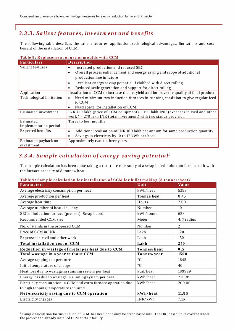
3.3.3. Salient features, investment and benefits
The following table describes the salient features, application, technological advantages, limitations and cost benefit of the installation of CCM:
Table 8: Replacement of use of moulds with CCM Particulars Description Salient features • Increased production and reduced SEC
• Overall process enhancement and energy saving and scope of additional production line in future
• Excellent energy saving potential if clubbed with direct rolling • Reduced scale generation and support for direct rolling
Application Installation of CCM to increase the net yield and improve the quality of final product Technological limitation • Need minimum two induction furnaces in running condition to give regular feed
to CCM • Need space for installation of CCM
Estimated investment INR 120 lakh (price of CCM equipment) + 150 lakh INR (expenses in civil and other work ) = 270 lakh INR (total investment) with two stands provision
Estimated implementation period
Three to four months
Expected benefits • Additional realisation of INR 100 lakh per annum for same production quantity • Savings in electricity by 10 to 12 kWh per heat
Estimated payback on investment
Approximately two to three years
3.3.4. Sample calculation of energy saving potential8
The sample calculation has been done taking a real-time case study of a scrap based induction furnace unit with the furnace capacity of 8 tonnes/heat.
Table 9: Sample calculation for installation of CCM for billet making (8 tonnes/heat) Parameters Unit Value Average electricity consumption per heat kWh/heat 5393 Average production per heat Tonnes/heat 8.45 Average heat time Hours 2.00 Average number of heats in a day Number 10 SEC of induction furnace (present): Scrap based kWh/tonne 638 Recommended CCM size Meter 4/7 radius
No. of stands in the proposed CCM Number 2 Price of CCM in INR Lakh 120 Expenses in civil and other work Lakh 150 Total installation cost of CCM Lakh 270 Reduction in wastage of metal per heat due to CCM Tonnes/heat 0.5 Total wastage in a year without CCM Tonnes/year 1500 Average tapping temperature °C 1645 Initial temperature of charge °C 40 Heat loss due to wastage in running system per heat kcal/heat 189929 Energy loss due to wastage in running system per heat kWh/heat 220.85 Electricity consumption in CCM and extra furnace operation due to high tapping temperature required
kWh/heat 209.00
Net electricity saving due to CCM operation kWh/heat 11.85 Electricity charges INR/kWh 7.16
8 Sample calculation for ‘installation of CCM’ has been done only for scrap based unit. The DRI based units covered under the project had already installed CCM at their facility.
Compendium of energy efficient technology measures for electric induction furnace (EIF) sector
Annual electricity saving due to CCM Lakh/year 2.54 Additional price on billets made through CCM INR/tonne 400 Additional profit due to CCM in INR Lakh 101.40 Total profit due to CCM in INR Lakh 103.94 Number of operating days in a year Number 300 Simple payback period months 31.17 GHG reduction potential9 tCO2/year 27.72
9 1 MWh =0.78 tCO2 (CEA user guide for CO2 Baseline Database Version 8 (2013))
Compendium of energy efficient technology measures for electric induction furnace (EIF) sector
3.4. Installation of sintering panel for sintering heat
3.4.1. Present practice
Refractory or ramming mass plays an important role as refractory/insulation material in the induction furnace. Thickness of refractory lining keeps on reducing with furnace operation. After every 15 to 20 heats, ramming mass needs resetting or replacement in order to avoid furnace breakdown. The first heat after ramming mass resetting is called sintering heat and takes almost double heat time compared to normal heat time (as it requires slow heating from ambient temperature to approximately 1660° C). The sintering heat consumes much more energy, ultimately reducing the overall SEC. The present status suggests that none of the units have given due importance to this aspect and have been losing on energy and production.
3.4.2. Proposed technology
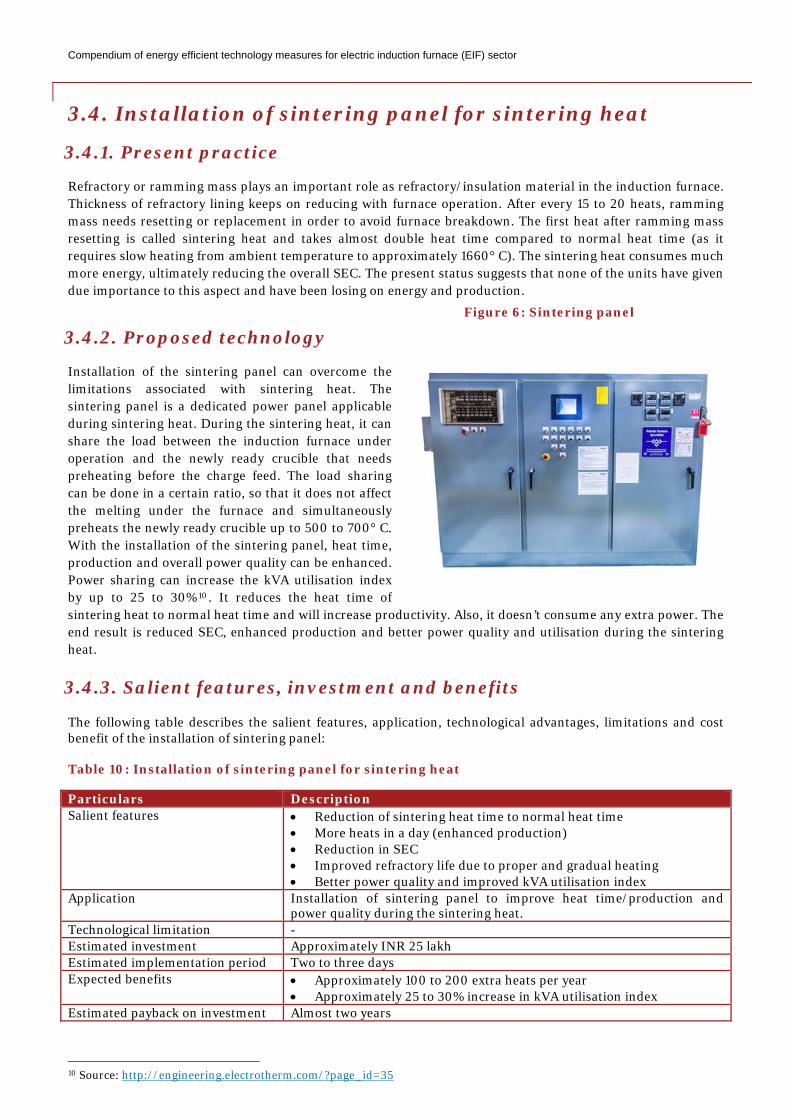
Installation of the sintering panel can overcome the limitations associated with sintering heat. The sintering panel is a dedicated power panel applicable during sintering heat. During the sintering heat, it can share the load between the induction furnace under operation and the newly ready crucible that needs preheating before the charge feed. The load sharing can be done in a certain ratio, so that it does not affect the melting under the furnace and simultaneously preheats the newly ready crucible up to 500 to 700° C. With the installation of the sintering panel, heat time, production and overall power quality can be enhanced. Power sharing can increase the kVA utilisation index by up to 25 to 30%10. It reduces the heat time of sintering heat to normal heat time and will increase productivity. Also, it doesn’t consume any extra power. The end result is reduced SEC, enhanced production and better power quality and utilisation during the sintering heat.
3.4.3. Salient features, investment and benefits
The following table describes the salient features, application, technological advantages, limitations and cost benefit of the installation of sintering panel:
Table 10: Installation of sintering panel for sintering heat
Particulars Description Salient features • Reduction of sintering heat time to normal heat time
• More heats in a day (enhanced production) • Reduction in SEC • Improved refractory life due to proper and gradual heating • Better power quality and improved kVA utilisation index
Application Installation of sintering panel to improve heat time/production and power quality during the sintering heat.
Technological limitation - Estimated investment Approximately INR 25 lakh Estimated implementation period Two to three days Expected benefits • Approximately 100 to 200 extra heats per year
• Approximately 25 to 30% increase in kVA utilisation index Estimated payback on investment Almost two years
10 Source: http://engineering.electrotherm.com/?page_id=35
Figure 6: Sintering panel
Compendium of energy efficient technology measures for electric induction furnace (EIF) sector
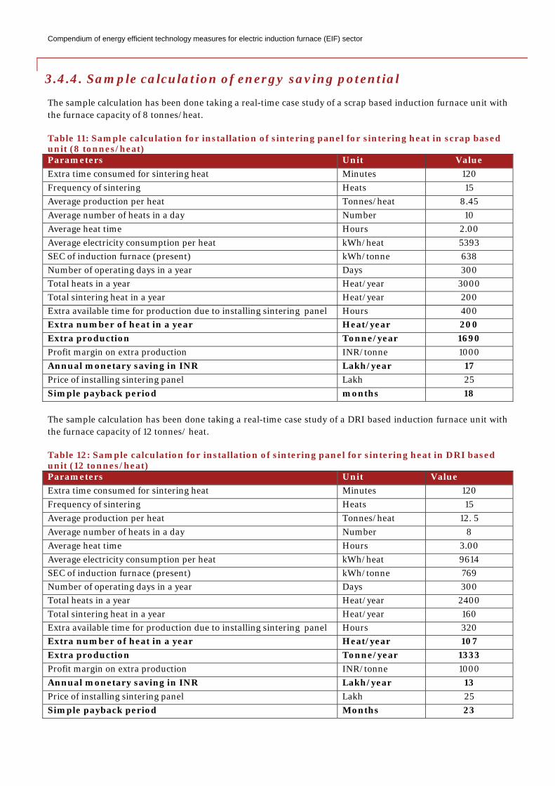
3.4.4. Sample calculation of energy saving potential
The sample calculation has been done taking a real-time case study of a scrap based induction furnace unit with the furnace capacity of 8 tonnes/heat.
Table 11: Sample calculation for installation of sintering panel for sintering heat in scrap based unit (8 tonnes/heat) Parameters Unit Value Extra time consumed for sintering heat Minutes 120 Frequency of sintering Heats 15 Average production per heat Tonnes/heat 8.45 Average number of heats in a day Number 10 Average heat time Hours 2.00 Average electricity consumption per heat kWh/heat 5393 SEC of induction furnace (present) kWh/tonne 638 Number of operating days in a year Days 300 Total heats in a year Heat/year 3000 Total sintering heat in a year Heat/year 200 Extra available time for production due to installing sintering panel Hours 400 Extra number of heat in a year Heat/year 200 Extra production Tonne/year 1690 Profit margin on extra production INR/tonne 1000 Annual monetary saving in INR Lakh/year 17 Price of installing sintering panel Lakh 25 Simple payback period months 18 The sample calculation has been done taking a real-time case study of a DRI based induction furnace unit with the furnace capacity of 12 tonnes/ heat.
Table 12: Sample calculation for installation of sintering panel for sintering heat in DRI based unit (12 tonnes/heat) Parameters Unit Value Extra time consumed for sintering heat Minutes 120 Frequency of sintering Heats 15 Average production per heat Tonnes/heat 12. 5 Average number of heats in a day Number 8 Average heat time Hours 3.00 Average electricity consumption per heat kWh/heat 9614 SEC of induction furnace (present) kWh/tonne 769 Number of operating days in a year Days 300 Total heats in a year Heat/year 2400 Total sintering heat in a year Heat/year 160 Extra available time for production due to installing sintering panel Hours 320 Extra number of heat in a year Heat/year 107 Extra production Tonne/year 1333 Profit margin on extra production INR/tonne 1000 Annual monetary saving in INR Lakh/year 13 Price of installing sintering panel Lakh 25 Simple payback period Months 23
C
3
3
Puthpc
3
Spbpfwf1 F
Irsr
3
Tb
Compendium of
3.5. Scr
3.5.1. Pr
Preheating ounits tried sctemperature heat/cycle timplant or evencan result in
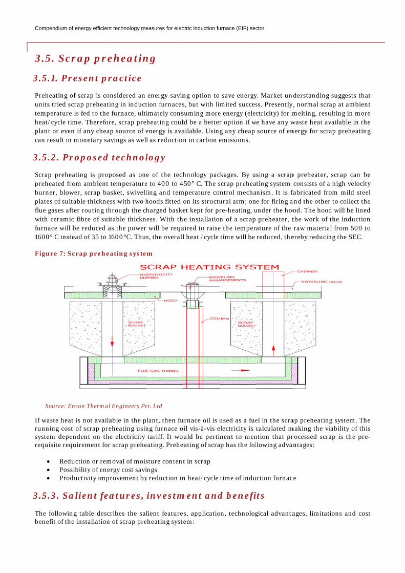
3.5.2. Pr
Scrap preheapreheated froburner, blowplates of suitflue gases aftwith ceramicfurnace will b1600° C inste
Figure 7: Sc
If waste heatrunning costsystem depenrequisite requ
• Redu• Possi• Prod
3.5.3. Sa
The followinbenefit of the
Source: En
f energy efficien
rap pre
esent pr
f scrap is cocrap preheati is fed to the me. Thereforn if any chea monetary sa
roposed
ating is propom ambient
wer, scrap baable thickne
ter routing thc fibre of suibe reduced aead of 35 to 1
crap prehe
t is not availat of scrap prendent on theuirement for
uction or remibility of ene
ductivity imp
alient fea
ng table desce installation
ncon Thermal
nt technology me
eheatin
ractice
nsidered an ing in induct furnace, ultire, scrap pre
ap source of eavings as well
technol
posed as one temperatureasket, swivellss with two h
hrough the chitable thicknas the power1600°C. Thus
ating syste
able in the peheating usine electricity r scrap prehe
moval of moisergy cost savirovement by
atures,
cribes the saln of scrap pre
l Engineers Pv
easures for elec
ng
energy-savintion furnacesimately consheating coulenergy is aval as reduction
logy
e of the teche to 400 to 4ling and temhoods fitted harged baskeess. With th will be requs, the overall
em
lant, then fung furnace o tariff. It woeating. Prehe
sture contentings y reduction in
investm
lient featureeheating syst
vt. Ltd
ctric induction fu
ng option tos, but with lisuming moreld be a betterailable. Usingn in carbon e
hnology pac450° C. The smperature co
on its structuet kept for pr
he installatiouired to raisel heat /cycle
urnace oil is uoil vis-à-vis eould be pertieating of scra
t in scrap
n heat/cycle
ment and
es, applicatiotem:
urnace (EIF) sec
save energymited succes
e energy (elecr option if wg any cheap emissions.
ckages. By uscrap preheantrol mechaural arm; onre-heating, un of a scrap
e the temper time will be
used as a fueelectricity is cnent to men
ap has the fol
time of indu
d benefi
on, technolog
ctor
y. Market undss. Presently,ctricity) for m
we have any w source of en
sing a scrapting system
anism. It is fae for firing a
under the hoo preheater, tature of the reduced, the
el in the scracalculated m
ntion that prllowing advan
uction furnac
its
gical advanta
nderstanding y, normal scramelting, resuwaste heat avnergy for scra
p preheater, consists of afabricated froand the otherod. The hoodthe work of raw materiaereby reducin
ap preheatingmaking the virocessed scra
antages:
ce
ages, limitat
suggests thaap at ambienulting in morvailable in thap preheatin
scrap can ba high velocitom mild steer to collect thd will be linethe inductio
al from 500 tng the SEC.
g system. Thiability of thiap is the pre
ions and cos
at nt re he ng
be ty el
he ed on to
he is e-
st
Compendium of energy efficient technology measures for electric induction furnace (EIF) sector
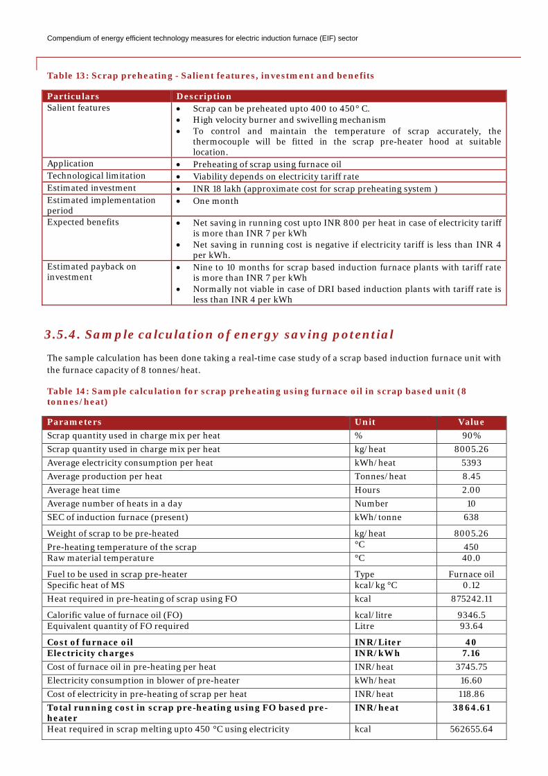
Table 13: Scrap preheating - Salient features, investment and benefits
Particulars Description Salient features • Scrap can be preheated upto 400 to 450° C.
• High velocity burner and swivelling mechanism • To control and maintain the temperature of scrap accurately, the
thermocouple will be fitted in the scrap pre-heater hood at suitable location.
Application • Preheating of scrap using furnace oil Technological limitation • Viability depends on electricity tariff rate Estimated investment • INR 18 lakh (approximate cost for scrap preheating system ) Estimated implementation period
• One month
Expected benefits • Net saving in running cost upto INR 800 per heat in case of electricity tariff is more than INR 7 per kWh
• Net saving in running cost is negative if electricity tariff is less than INR 4 per kWh.
Estimated payback on investment
• Nine to 10 months for scrap based induction furnace plants with tariff rate is more than INR 7 per kWh
• Normally not viable in case of DRI based induction plants with tariff rate is less than INR 4 per kWh
3.5.4. Sample calculation of energy saving potential
The sample calculation has been done taking a real-time case study of a scrap based induction furnace unit with the furnace capacity of 8 tonnes/heat.
Table 14: Sample calculation for scrap preheating using furnace oil in scrap based unit (8 tonnes/heat)
Parameters Unit Value Scrap quantity used in charge mix per heat % 90% Scrap quantity used in charge mix per heat kg/heat 8005.26 Average electricity consumption per heat kWh/heat 5393 Average production per heat Tonnes/heat 8.45 Average heat time Hours 2.00 Average number of heats in a day Number 10 SEC of induction furnace (present) kWh/tonne 638
Weight of scrap to be pre-heated kg/heat 8005.26 Pre-heating temperature of the scrap °C 450 Raw material temperature °C 40.0
Fuel to be used in scrap pre-heater Type Furnace oil Specific heat of MS kcal/kg °C 0.12 Heat required in pre-heating of scrap using FO kcal 875242.11
Calorific value of furnace oil (FO) kcal/litre 9346.5 Equivalent quantity of FO required Litre 93.64
Cost of furnace oil INR/Liter 40 Electricity charges INR/kWh 7.16 Cost of furnace oil in pre-heating per heat INR/heat 3745.75 Electricity consumption in blower of pre-heater kWh/heat 16.60 Cost of electricity in pre-heating of scrap per heat INR/heat 118.86 Total running cost in scrap pre-heating using FO based pre-heater
INR/heat 3864.61
Heat required in scrap melting upto 450 °C using electricity kcal 562655.64
Compendium of energy efficient technology measures for electric induction furnace (EIF) sector
Calorific value of electricity kcal/kWh 860 Equivalent quantity of electricity required kWh 654.25 Cost of electricity in melting scrap per heat INR/heat 4684.44 Net savings in cost for heating scrap/melt vis-à-vis to electricity
INR/heat 819.83
Number of operating days in a year Number 300 Annual monetary saving in INR Lakh/year 24.59 Price of scrap pre-heating system Lakh 18.00 Simple payback period Months 8.78
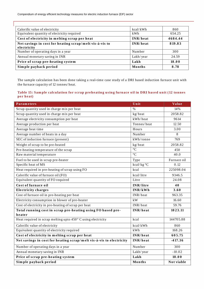
The sample calculation has been done taking a real-time case study of a DRI based induction furnace unit with the furnace capacity of 12 tonnes/heat.
Table 15: Sample calculation for scrap preheating using furnace oil in DRI based unit (12 tonnes per heat)
Parameters Unit Value Scrap quantity used in charge mix per heat % 14% Scrap quantity used in charge mix per heat kg/heat 2058.82 Average electricity consumption per heat kWh/heat 9614 Average production per heat Tonnes/heat 12.50 Average heat time Hours 3.00 Average number of heats in a day Number 8 SEC of induction furnace (present) kWh/tonne 769
Weight of scrap to be pre-heated kg/heat 2058.82 Pre-heating temperature of the scrap °C 450 Raw material temperature °C 40.0
Fuel to be used in scrap pre-heater Type Furnace oil Specific heat of MS kcal/kg °C 0.12 Heat required in pre-heating of scrap using FO kcal 225098.04
Calorific value of furnace oil (FO) kcal/litre 9346.5 Equivalent quantity of FO required Litre 24.08
Cost of furnace oil INR/litre 40 Electricity charges INR/kWh 3.60 Cost of furnace oil in pre-heating per heat INR/heat 963.35 Electricity consumption in blower of pre-heater kW 16.60 Cost of electricity in pre-heating of scrap per heat INR/heat 59.76 Total running cost in scrap pre-heating using FO based pre-heater
INR/heat 1023.11
Heat required in scrap melting upto 450° C using electricity kcal 144705.88
Calorific value of electricity kcal/kWh 860 Equivalent quantity of electricity required kWh 168.26 Cost of electricity in melting scrap per heat INR/heat 605.75 Net savings in cost for heating scrap/melt vis-à-vis to electricity INR/heat -417.36
Number of operating days in a year Number 300 Annual monetary saving in INR Lakh/year -10.02 Price of scrap pre-heating system Lakh 18.00 Simple payback period Months Not viable
C
3
3
TliD
3
LhCf(c
Toa
3
Tb T
Compendium of
3.6. La
3.6.1. Pr
The partiallyadle therebyncreased by
Due to this, h
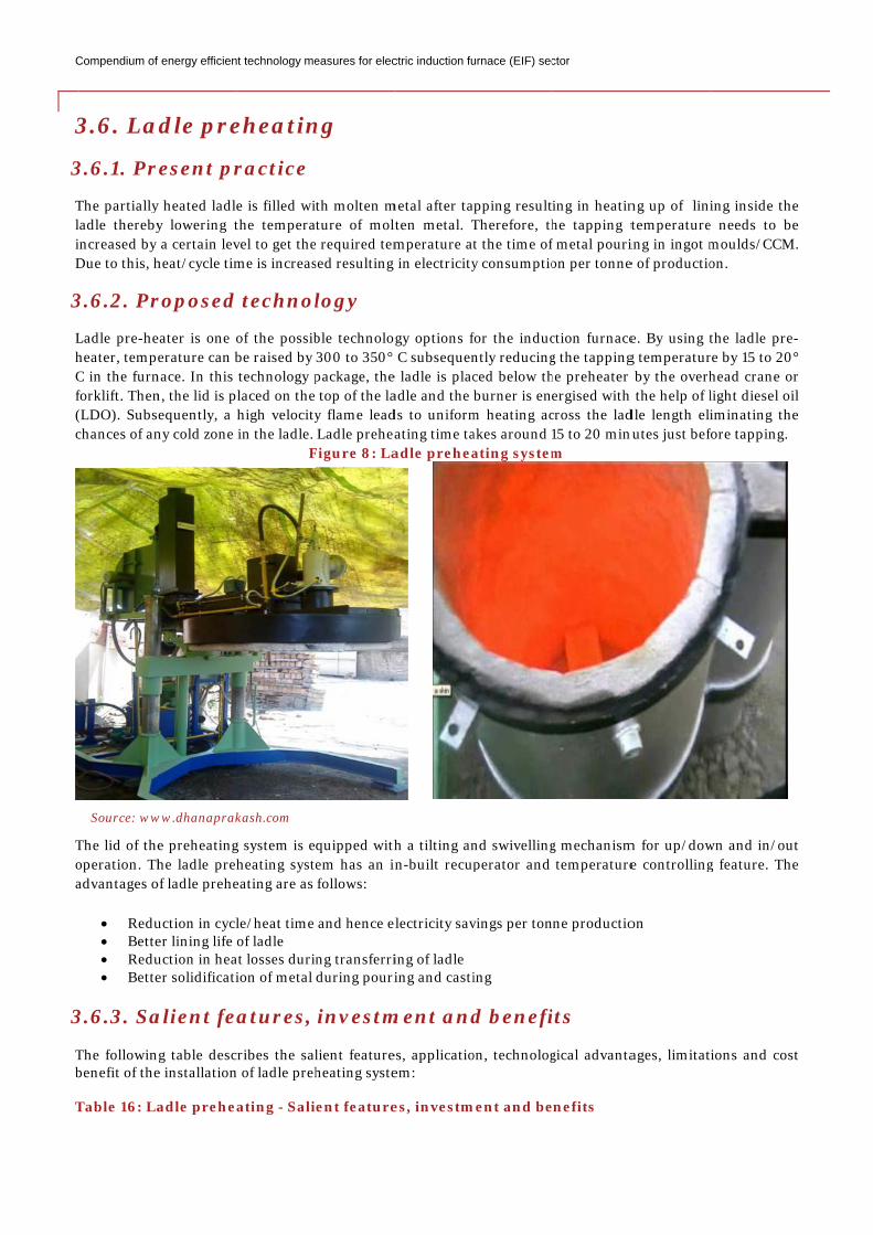
3.6.2. Pr
Ladle pre-heheater, tempeC in the furnforklift. Then(LDO). Subschances of an
The lid of theoperation. Thadvantages o
• Redu• Bette• Redu• Bette
3.6.3. Sa
The followinbenefit of the
Table 16: La
Source: ww
f energy efficien
adle pre
resent pr
y heated ladley lowering t a certain levheat/cycle tim
roposed
eater is one oerature can b
nace. In this n, the lid is pequently, a
ny cold zone
e preheatinghe ladle preh
of ladle prehe
uction in cycler lining life uction in heaer solidificati
alient fe
ng table desce installation
adle prehe
ww.dhanaprak
nt technology me
eheatin
ractice
e is filled withe temperavel to get theme is increas
d technol
of the possibbe raised by technology placed on thehigh velocity in the ladle.
F
g system is eheating syst
eating are as
le/heat time of ladle
at losses duriion of metal
atures,
cribes the saln of ladle preh
ating - Sali
kash.com
easures for elec
ng
th molten mture of mol
e required temsed resulting
logy
ble technolog300 to 350° package, the top of the lay flame lead Ladle prehea
Figure 8: La
quipped withem has an i follows:
and hence e
ng transferri during pouri
investm
lient featureheating syste
ent feature
ctric induction fu
metal after talten metal. Tmperature at in electricity
gy options f C subsequen
e ladle is placadle and the ds to uniformating time taadle prehea
h a tilting ann-built recup
electricity sav
ing of ladle ing and casti
ment and
es, applicatioem:
es, investm
urnace (EIF) sec
apping resultTherefore, tht the time ofy consumptio
for the inducntly reducingced below thburner is en
m heating acakes around 1ating system
nd swivellingperator and
vings per ton
ing
d benefi
on, technolog
ment and be
ctor
ing in heatinhe tapping tf metal pourion per tonne
ction furnaceg the tappinghe preheater ergised with
cross the lad15 to 20 minm
g mechanism temperature
ne productio
its
gical advanta
enefits
ng up of linitemperatureing in ingot me of productio
e. By using tg temperatur by the overh
h the help of ldle length elinutes just bef
m for up/dowe controlling
on
ages, limitat
ing inside the needs to bmoulds/CCMon.
the ladle prere by 15 to 20head crane olight diesel oiminating th
fore tapping.
wn and in/oug feature. Th
ions and cos
he be M.
e-0° or oil he
ut he
st
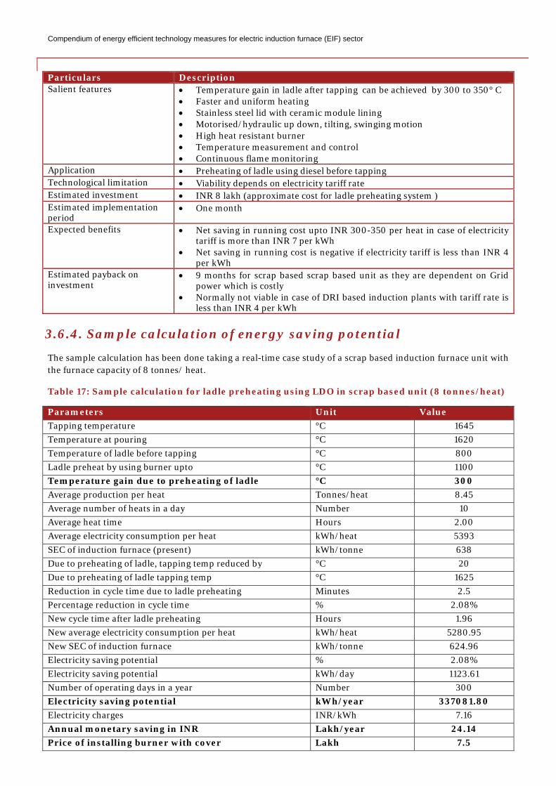
Compendium of energy efficient technology measures for electric induction furnace (EIF) sector
Particulars Description Salient features • Temperature gain in ladle after tapping can be achieved by 300 to 350° C
• Faster and uniform heating • Stainless steel lid with ceramic module lining • Motorised/hydraulic up down, tilting, swinging motion • High heat resistant burner • Temperature measurement and control • Continuous flame monitoring
Application • Preheating of ladle using diesel before tapping Technological limitation • Viability depends on electricity tariff rate Estimated investment • INR 8 lakh (approximate cost for ladle preheating system ) Estimated implementation period
• One month
Expected benefits • Net saving in running cost upto INR 300-350 per heat in case of electricity tariff is more than INR 7 per kWh
• Net saving in running cost is negative if electricity tariff is less than INR 4 per kWh
Estimated payback on investment
• 9 months for scrap based scrap based unit as they are dependent on Grid power which is costly
• Normally not viable in case of DRI based induction plants with tariff rate is less than INR 4 per kWh
3.6.4. Sample calculation of energy saving potential
The sample calculation has been done taking a real-time case study of a scrap based induction furnace unit with the furnace capacity of 8 tonnes/ heat.
Table 17: Sample calculation for ladle preheating using LDO in scrap based unit (8 tonnes/heat)
Parameters Unit Value Tapping temperature °C 1645 Temperature at pouring °C 1620 Temperature of ladle before tapping °C 800 Ladle preheat by using burner upto °C 1100 Temperature gain due to preheating of ladle °C 300 Average production per heat Tonnes/heat 8.45 Average number of heats in a day Number 10 Average heat time Hours 2.00 Average electricity consumption per heat kWh/heat 5393 SEC of induction furnace (present) kWh/tonne 638 Due to preheating of ladle, tapping temp reduced by °C 20 Due to preheating of ladle tapping temp °C 1625 Reduction in cycle time due to ladle preheating Minutes 2.5 Percentage reduction in cycle time % 2.08% New cycle time after ladle preheating Hours 1.96 New average electricity consumption per heat kWh/heat 5280.95 New SEC of induction furnace kWh/tonne 624.96 Electricity saving potential % 2.08% Electricity saving potential kWh/day 1123.61 Number of operating days in a year Number 300 Electricity saving potential kWh/year 337081.80 Electricity charges INR/kWh 7.16 Annual monetary saving in INR Lakh/year 24.14 Price of installing burner with cover Lakh 7.5
Compendium of energy efficient technology measures for electric induction furnace (EIF) sector
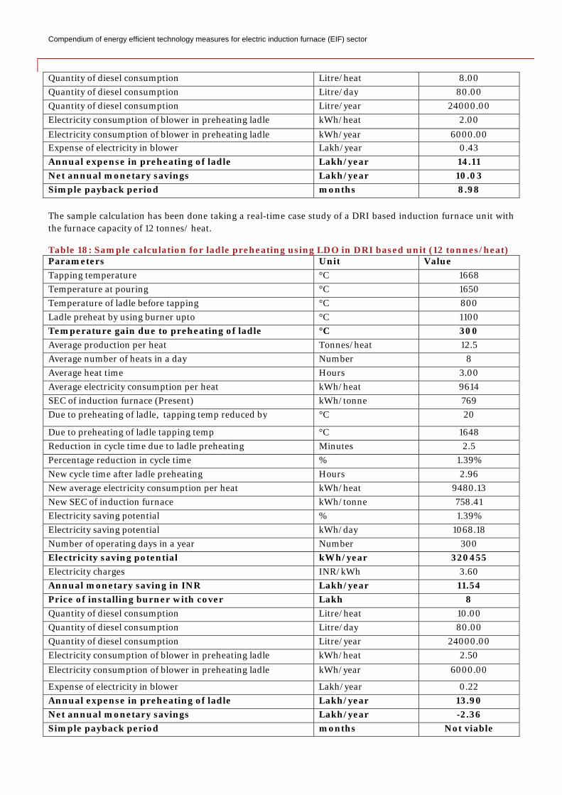
Quantity of diesel consumption Litre/heat 8.00 Quantity of diesel consumption Litre/day 80.00 Quantity of diesel consumption Litre/year 24000.00 Electricity consumption of blower in preheating ladle kWh/heat 2.00 Electricity consumption of blower in preheating ladle kWh/year 6000.00 Expense of electricity in blower Lakh/year 0.43 Annual expense in preheating of ladle Lakh/year 14.11 Net annual monetary savings Lakh/year 10.03 Simple payback period months 8.98 The sample calculation has been done taking a real-time case study of a DRI based induction furnace unit with the furnace capacity of 12 tonnes/ heat.
Table 18: Sample calculation for ladle preheating using LDO in DRI based unit (12 tonnes/heat) Parameters Unit Value Tapping temperature °C 1668 Temperature at pouring °C 1650 Temperature of ladle before tapping °C 800 Ladle preheat by using burner upto °C 1100 Temperature gain due to preheating of ladle °C 300 Average production per heat Tonnes/heat 12.5 Average number of heats in a day Number 8 Average heat time Hours 3.00 Average electricity consumption per heat kWh/heat 9614 SEC of induction furnace (Present) kWh/tonne 769 Due to preheating of ladle, tapping temp reduced by °C 20
Due to preheating of ladle tapping temp °C 1648 Reduction in cycle time due to ladle preheating Minutes 2.5 Percentage reduction in cycle time % 1.39% New cycle time after ladle preheating Hours 2.96 New average electricity consumption per heat kWh/heat 9480.13 New SEC of induction furnace kWh/tonne 758.41 Electricity saving potential % 1.39% Electricity saving potential kWh/day 1068.18 Number of operating days in a year Number 300 Electricity saving potential kWh/year 320455 Electricity charges INR/kWh 3.60 Annual monetary saving in INR Lakh/year 11.54 Price of installing burner with cover Lakh 8 Quantity of diesel consumption Litre/heat 10.00 Quantity of diesel consumption Litre/day 80.00 Quantity of diesel consumption Litre/year 24000.00 Electricity consumption of blower in preheating ladle kWh/heat 2.50 Electricity consumption of blower in preheating ladle kWh/year 6000.00
Expense of electricity in blower Lakh/year 0.22 Annual expense in preheating of ladle Lakh/year 13.90 Net annual monetary savings Lakh/year -2.36 Simple payback period months Not viable
Compendium of energy efficient technology measures for electric induction furnace (EIF) sector
3.7. Avoid superheating of the metals
3.7.1. Present practice
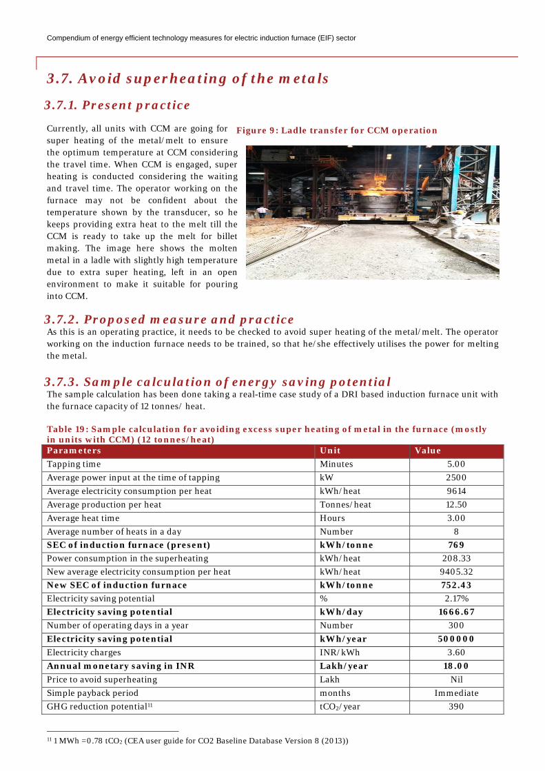
Currently, all units with CCM are going for super heating of the metal/melt to ensure the optimum temperature at CCM considering the travel time. When CCM is engaged, super heating is conducted considering the waiting and travel time. The operator working on the furnace may not be confident about the temperature shown by the transducer, so he keeps providing extra heat to the melt till the CCM is ready to take up the melt for billet making. The image here shows the molten metal in a ladle with slightly high temperature due to extra super heating, left in an open environment to make it suitable for pouring into CCM.
3.7.2. Proposed measure and practice As this is an operating practice, it needs to be checked to avoid super heating of the metal/melt. The operator working on the induction furnace needs to be trained, so that he/she effectively utilises the power for melting the metal.
3.7.3. Sample calculation of energy saving potential The sample calculation has been done taking a real-time case study of a DRI based induction furnace unit with the furnace capacity of 12 tonnes/ heat.
Table 19: Sample calculation for avoiding excess super heating of metal in the furnace (mostly in units with CCM) (12 tonnes/heat) Parameters Unit Value Tapping time Minutes 5.00 Average power input at the time of tapping kW 2500 Average electricity consumption per heat kWh/heat 9614 Average production per heat Tonnes/heat 12.50 Average heat time Hours 3.00 Average number of heats in a day Number 8 SEC of induction furnace (present) kWh/tonne 769 Power consumption in the superheating kWh/heat 208.33 New average electricity consumption per heat kWh/heat 9405.32 New SEC of induction furnace kWh/tonne 752.43 Electricity saving potential % 2.17% Electricity saving potential kWh/day 1666.67 Number of operating days in a year Number 300 Electricity saving potential kWh/year 500000 Electricity charges INR/kWh 3.60 Annual monetary saving in INR Lakh/year 18.00 Price to avoid superheating Lakh Nil Simple payback period months Immediate GHG reduction potential11 tCO2/year 390
11 1 MWh =0.78 tCO2 (CEA user guide for CO2 Baseline Database Version 8 (2013))
Figure 9: Ladle transfer for CCM operation
Compendium of energy efficient technology measures for electric induction furnace (EIF) sector
3.8. Avoid overfilling (metal above the coil level) of furnace during melting
3.8.1. Present practice
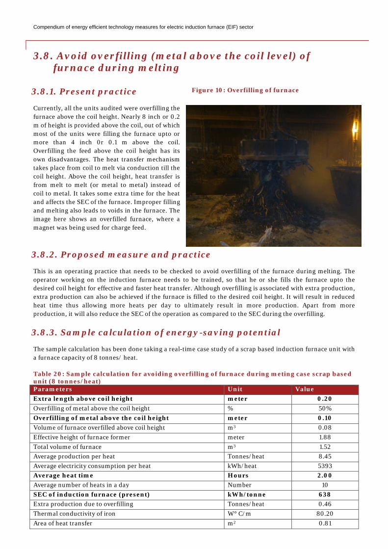
Currently, all the units audited were overfilling the furnace above the coil height. Nearly 8 inch or 0.2 m of height is provided above the coil, out of which most of the units were filling the furnace upto or more than 4 inch 0r 0.1 m above the coil. Overfilling the feed above the coil height has its own disadvantages. The heat transfer mechanism takes place from coil to melt via conduction till the coil height. Above the coil height, heat transfer is from melt to melt (or metal to metal) instead of coil to metal. It takes some extra time for the heat and affects the SEC of the furnace. Improper filling and melting also leads to voids in the furnace. The image here shows an overfilled furnace, where a magnet was being used for charge feed.
3.8.2. Proposed measure and practice
This is an operating practice that needs to be checked to avoid overfilling of the furnace during melting. The operator working on the induction furnace needs to be trained, so that he or she fills the furnace upto the desired coil height for effective and faster heat transfer. Although overfilling is associated with extra production, extra production can also be achieved if the furnace is filled to the desired coil height. It will result in reduced heat time thus allowing more heats per day to ultimately result in more production. Apart from more production, it will also reduce the SEC of the operation as compared to the SEC during the overfilling.
3.8.3. Sample calculation of energy-saving potential
The sample calculation has been done taking a real-time case study of a scrap based induction furnace unit with a furnace capacity of 8 tonnes/ heat.
Table 20: Sample calculation for avoiding overfilling of furnace during meting case scrap based unit (8 tonnes/heat) Parameters Unit Value Extra length above coil height meter 0.20 Overfilling of metal above the coil height % 50% Overfilling of metal above the coil height meter 0.10 Volume of furnace overfilled above coil height m3 0.08 Effective height of furnace former meter 1.88 Total volume of furnace m3 1.52 Average production per heat Tonnes/heat 8.45 Average electricity consumption per heat kWh/heat 5393 Average heat time Hours 2.00 Average number of heats in a day Number 10 SEC of induction furnace (present) kWh/tonne 638 Extra production due to overfilling Tonnes/heat 0.46 Thermal conductivity of iron W° C/m 80.20 Area of heat transfer m2 0.81
Figure 10: Overfilling of furnace
Compendium of energy efficient technology measures for electric induction furnace (EIF) sector
Thickness m 0.10 Average tapping temperature °C 1645 Initial temperature of charge °C 40 Heat Transfer in conduction heating of overfilled metal kW 1026.63 Heat loss due to overfilling in a heat kcal 147624 Heat loss due to overfilling in a heat kWh 171.66 Extra time in melting due to overfilling Minutes 10.03 New cycle time after avoiding overfilling of furnace during the melting
Hours 1.83
New average electricity consumption per heat kWh/heat 4942.42 New SEC of induction furnace kWh/tonne 618.32 Electricity saving potential % 3.12% Electricity saving potential kWh/day 1684.66 Number of operating days in a year Number 300 Electricity saving potential kWh/year 505398.50 Electricity charges INR/kWh 7.16 Annual monetary saving in INR Lakh/year 36.19 Price to avoid overfilling Lakh Nil Simple payback period months Immediate GHG reduction potential12 tCO2/year 394.21
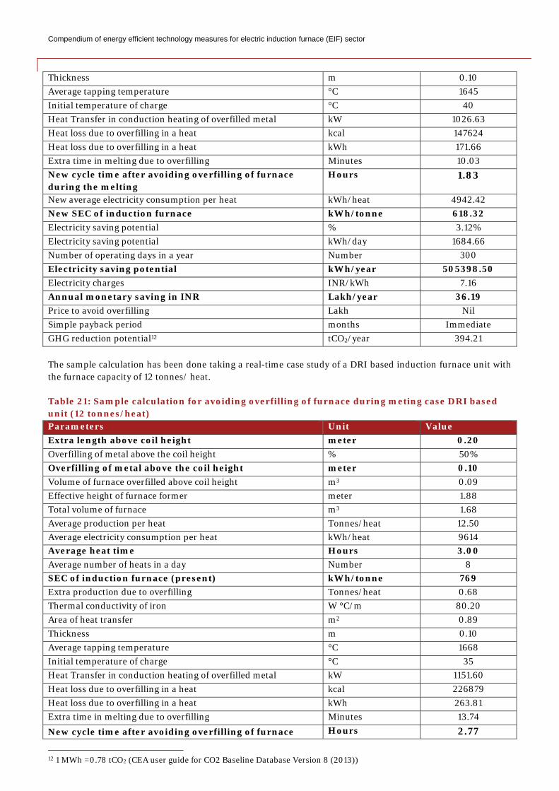
The sample calculation has been done taking a real-time case study of a DRI based induction furnace unit with the furnace capacity of 12 tonnes/ heat. Table 21: Sample calculation for avoiding overfilling of furnace during meting case DRI based unit (12 tonnes/heat) Parameters Unit Value Extra length above coil height meter 0.20 Overfilling of metal above the coil height % 50% Overfilling of metal above the coil height meter 0.10 Volume of furnace overfilled above coil height m3 0.09 Effective height of furnace former meter 1.88 Total volume of furnace m3 1.68 Average production per heat Tonnes/heat 12.50 Average electricity consumption per heat kWh/heat 9614 Average heat time Hours 3.00 Average number of heats in a day Number 8 SEC of induction furnace (present) kWh/tonne 769 Extra production due to overfilling Tonnes/heat 0.68 Thermal conductivity of iron W °C/m 80.20 Area of heat transfer m2 0.89 Thickness m 0.10 Average tapping temperature °C 1668 Initial temperature of charge °C 35 Heat Transfer in conduction heating of overfilled metal kW 1151.60 Heat loss due to overfilling in a heat kcal 226879 Heat loss due to overfilling in a heat kWh 263.81 Extra time in melting due to overfilling Minutes 13.74
New cycle time after avoiding overfilling of furnace Hours 2.77
12 1 MWh =0.78 tCO2 (CEA user guide for CO2 Baseline Database Version 8 (2013))
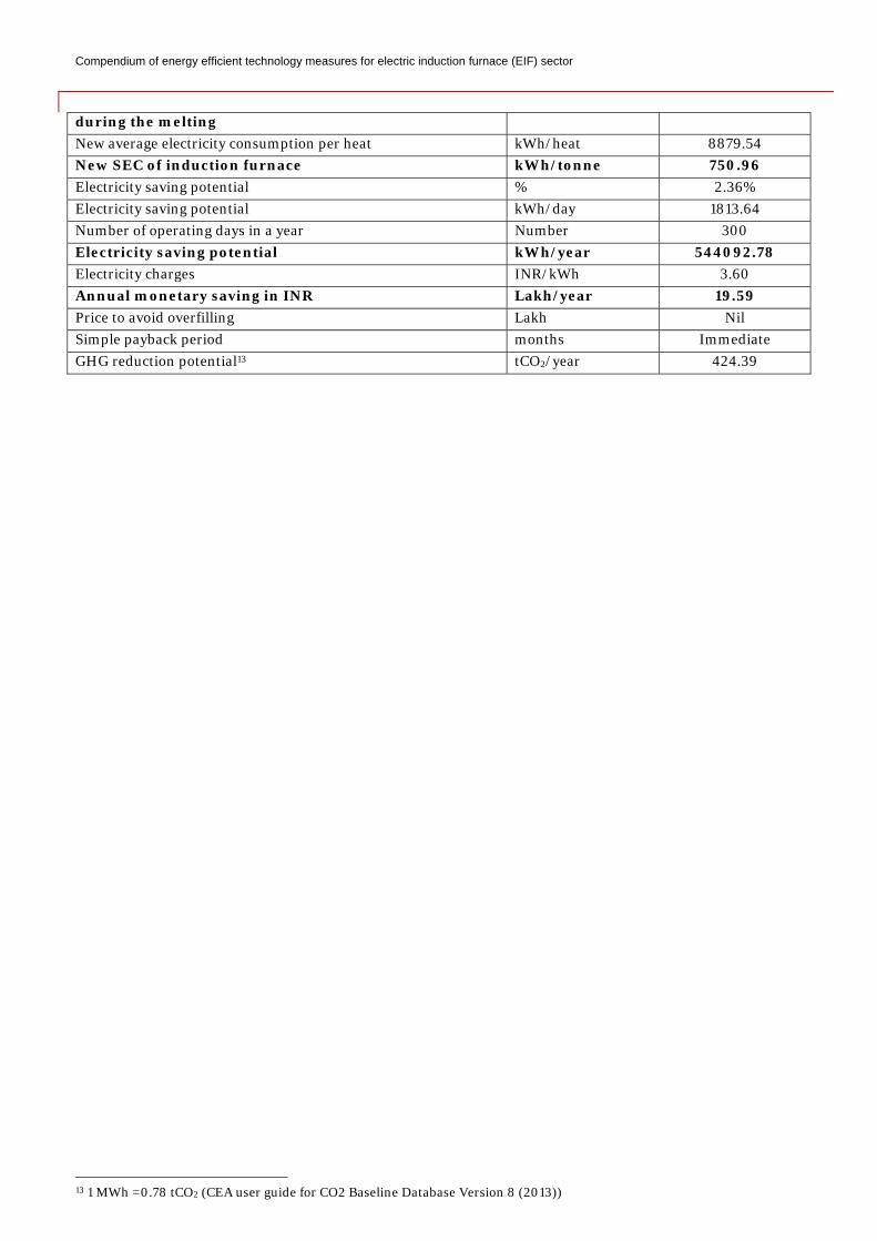
Compendium of energy efficient technology measures for electric induction furnace (EIF) sector
during the melting New average electricity consumption per heat kWh/heat 8879.54 New SEC of induction furnace kWh/tonne 750.96 Electricity saving potential % 2.36% Electricity saving potential kWh/day 1813.64 Number of operating days in a year Number 300 Electricity saving potential kWh/year 544092.78 Electricity charges INR/kWh 3.60 Annual monetary saving in INR Lakh/year 19.59 Price to avoid overfilling Lakh Nil Simple payback period months Immediate GHG reduction potential13 tCO2/year 424.39
13 1 MWh =0.78 tCO2 (CEA user guide for CO2 Baseline Database Version 8 (2013))
Compendium of energy efficient technology measures for electric induction furnace (EIF) sector
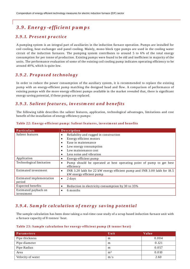
3.9. Energy-efficient pumps
3.9.1. Present practice
A pumping system is an integral part of auxiliaries in the induction furnace operation. Pumps are installed for coil cooling, heat exchanger and panel cooling. Mainly, mono block type pumps are used in the cooling water circuit of the induction furnaces. The pumping system contributes to around 5 to 6% of the total energy consumption for per tonne of production. Existing pumps were found to be old and inefficient in majority of the units. The performance evaluation of some of the existing coil cooling pump indicates operating efficiency to be around 40%, which is quite low.
3.9.2. Proposed technology
In order to reduce the power consumption of the auxiliary system, it is recommended to replace the existing pump with an energy-efficient pump matching the designed head and flow. A comparison of performance of existing pumps with the more energy efficient pumps available in the market revealed that, there is significant energy saving potential, if these pumps are replaced.
3.9.3. Salient features, investment and benefits
The following table describes the salient features, application, technological advantages, limitations and cost benefit of the installation of energy efficiency pumps: Table 22: Energy-efficient pump: Salient features, investment and benefits
Particulars Description Salient features • Reliability and rugged in construction
• Energy efficient motors • Ease in maintenance • Low energy consumption • Low maintenance cost • Less noise and vibration
Application • Energy-efficient pump Technological limitation • Pump should be operated at best operating point of pump to get best
efficiency Estimated investment • INR 3.20 lakh for 22 kW energy efficient pump and INR 3.00 lakh for 18.5
kW energy efficient pump Estimated implementation period
• 2 days
Expected benefits • Reduction in electricity consumption by 30 to 35% Estimated payback on investment
• 6 months
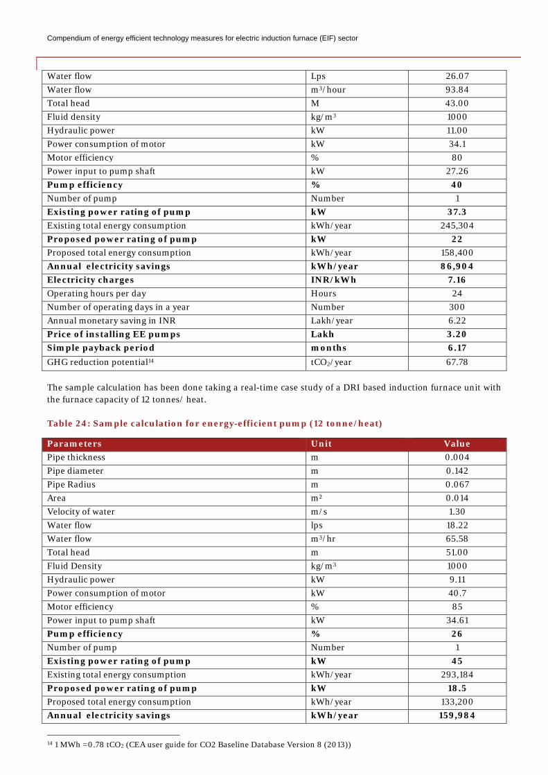
3.9.4. Sample calculation of energy saving potential
The sample calculation has been done taking a real-time case study of a scrap based induction furnace unit with a furnace capacity of 8 tonnes/ heat. Table 23: Sample calculation for energy-efficient pump (8 tonne/heat)
Parameters Unit Value Pipe thickness m 0.004 Pipe diameter m 0.121 Pipe Radius m 0.057 Area m² 0.010 Velocity of water m/s 2.60
Compendium of energy efficient technology measures for electric induction furnace (EIF) sector
Water flow Lps 26.07 Water flow m3/hour 93.84 Total head M 43.00 Fluid density kg/m3 1000 Hydraulic power kW 11.00 Power consumption of motor kW 34.1 Motor efficiency % 80 Power input to pump shaft kW 27.26 Pump efficiency % 40 Number of pump Number 1 Existing power rating of pump kW 37.3 Existing total energy consumption kWh/year 245,304 Proposed power rating of pump kW 22 Proposed total energy consumption kWh/year 158,400 Annual electricity savings kWh/year 86,904 Electricity charges INR/kWh 7.16 Operating hours per day Hours 24 Number of operating days in a year Number 300 Annual monetary saving in INR Lakh/year 6.22 Price of installing EE pumps Lakh 3.20 Simple payback period months 6.17 GHG reduction potential14 tCO2/year 67.78
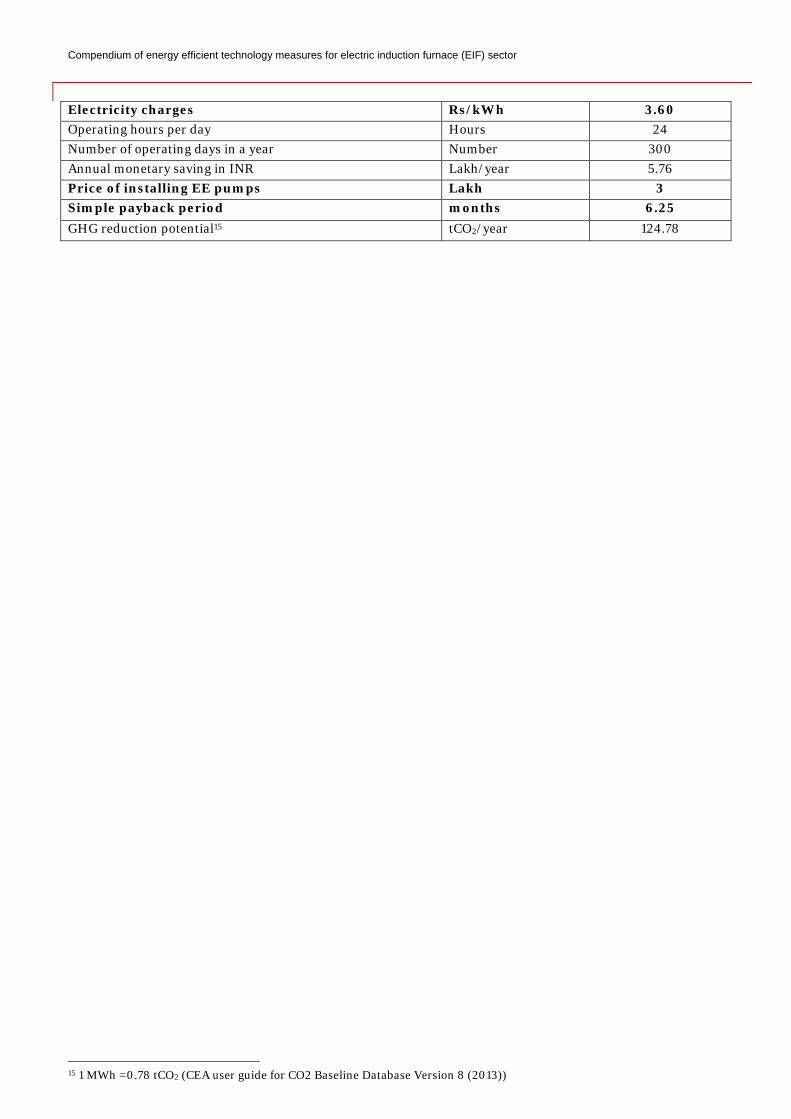
The sample calculation has been done taking a real-time case study of a DRI based induction furnace unit with the furnace capacity of 12 tonnes/ heat. Table 24: Sample calculation for energy-efficient pump (12 tonne/heat)
Parameters Unit Value Pipe thickness m 0.004 Pipe diameter m 0.142 Pipe Radius m 0.067 Area m² 0.014 Velocity of water m/s 1.30 Water flow lps 18.22 Water flow m3/hr 65.58 Total head m 51.00 Fluid Density kg/m3 1000 Hydraulic power kW 9.11 Power consumption of motor kW 40.7 Motor efficiency % 85 Power input to pump shaft kW 34.61 Pump efficiency % 26 Number of pump Number 1 Existing power rating of pump kW 45 Existing total energy consumption kWh/year 293,184 Proposed power rating of pump kW 18.5 Proposed total energy consumption kWh/year 133,200 Annual electricity savings kWh/year 159,984
14 1 MWh =0.78 tCO2 (CEA user guide for CO2 Baseline Database Version 8 (2013))
Compendium of energy efficient technology measures for electric induction furnace (EIF) sector
Electricity charges Rs/kWh 3.60 Operating hours per day Hours 24 Number of operating days in a year Number 300 Annual monetary saving in INR Lakh/year 5.76 Price of installing EE pumps Lakh 3 Simple payback period months 6.25 GHG reduction potential15 tCO2/year 124.78
15 1 MWh =0.78 tCO2 (CEA user guide for CO2 Baseline Database Version 8 (2013))
Compendium of energy efficient technology measures for electric induction furnace (EIF) sector
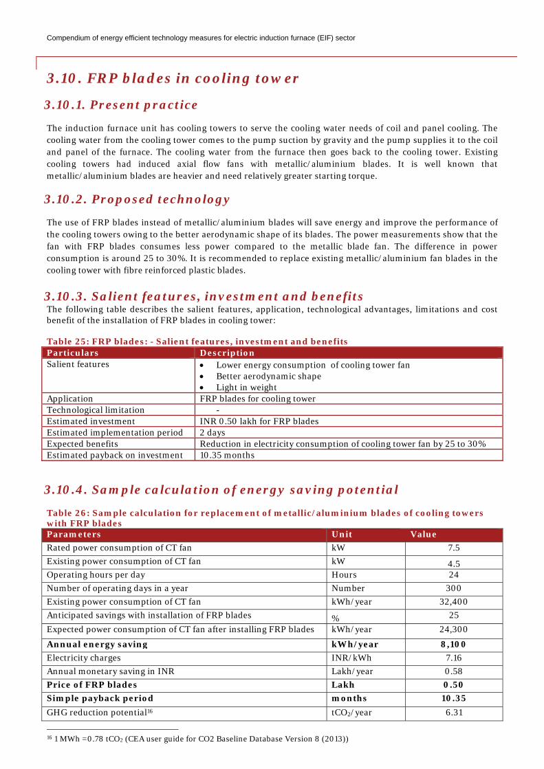
3.10. FRP blades in cooling tower
3.10.1. Present practice
The induction furnace unit has cooling towers to serve the cooling water needs of coil and panel cooling. The cooling water from the cooling tower comes to the pump suction by gravity and the pump supplies it to the coil and panel of the furnace. The cooling water from the furnace then goes back to the cooling tower. Existing cooling towers had induced axial flow fans with metallic/aluminium blades. It is well known that metallic/aluminium blades are heavier and need relatively greater starting torque.
3.10.2. Proposed technology
The use of FRP blades instead of metallic/aluminium blades will save energy and improve the performance of the cooling towers owing to the better aerodynamic shape of its blades. The power measurements show that the fan with FRP blades consumes less power compared to the metallic blade fan. The difference in power consumption is around 25 to 30%. It is recommended to replace existing metallic/aluminium fan blades in the cooling tower with fibre reinforced plastic blades.
3.10.3. Salient features, investment and benefits The following table describes the salient features, application, technological advantages, limitations and cost benefit of the installation of FRP blades in cooling tower: Table 25: FRP blades: - Salient features, investment and benefits Particulars Description Salient features • Lower energy consumption of cooling tower fan
• Better aerodynamic shape • Light in weight
Application FRP blades for cooling tower Technological limitation - Estimated investment INR 0.50 lakh for FRP blades Estimated implementation period 2 days Expected benefits Reduction in electricity consumption of cooling tower fan by 25 to 30% Estimated payback on investment 10.35 months
3.10.4. Sample calculation of energy saving potential
Table 26: Sample calculation for replacement of metallic/aluminium blades of cooling towers with FRP blades Parameters Unit Value Rated power consumption of CT fan kW 7.5 Existing power consumption of CT fan kW 4.5 Operating hours per day Hours 24 Number of operating days in a year Number 300 Existing power consumption of CT fan kWh/year 32,400 Anticipated savings with installation of FRP blades % 25 Expected power consumption of CT fan after installing FRP blades kWh/year 24,300
Annual energy saving kWh/year 8,100 Electricity charges INR/kWh 7.16 Annual monetary saving in INR Lakh/year 0.58 Price of FRP blades Lakh 0.50 Simple payback period months 10.35 GHG reduction potential16 tCO2/year 6.31
16 1 MWh =0.78 tCO2 (CEA user guide for CO2 Baseline Database Version 8 (2013))
Compendium of energy efficient technology measures for electric induction furnace (EIF) sector
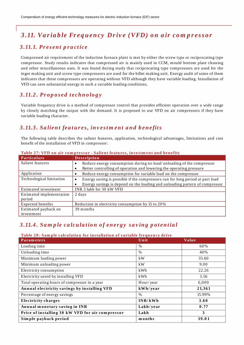
3.11. Variable Frequency Drive (VFD) on air compressor
3.11.1. Present practice
Compressed air requirement of the induction furnace plant is met by either the screw type or reciprocating type compressor. Study results indicates that compressed air is mainly used in CCM, mould bottom plate cleaning and other miscellaneous uses. It was found during study that reciprocating type compressors are used for the ingot making unit and screw type compressors are used for the billet making unit. Energy audit of some of them indicates that these compressors are operating without VFD although they have variable loading. Installation of VFD can save substantial energy in such a variable loading conditions.
3.11.2. Proposed technology
Variable frequency drive is a method of compressor control that provides efficient operation over a wide range by closely matching the output with the demand. It is proposed to use VFD on air compressors if they have variable loading character.
3.11.3. Salient features, investment and benefits
The following table describes the salient features, application, technological advantages, limitations and cost benefit of the installation of VFD in compressor: Table 27: VFD on air compressor - Salient features, investment and benefits Particulars Description Salient features • Reduce energy consumption during no load/unloading of the compressor
• Better controlling of operation and lowering the operating pressure Application • Reduce energy consumption for variable load on the compressor Technological limitation • Energy saving is possible if the compressors run for long period at part load
• Energy savings is depend on the loading and unloading pattern of compressor Estimated investment INR 3 lakh for 30 kW VFD Estimated implementation period
2 days
Expected benefits Reduction in electricity consumption by 15 to 20% Estimated payback on investment
39 months
3.11.4. Sample calculation of energy saving potential
Table 28: Sample calculation for installation of variable frequency drive Parameters Unit Value Loading time % 60% Unloading time % 40% Maximum loading power kW 35.60 Minimum unloading power kW 9.00 Electricity consumption kWh 22.26 Electricity saved by installing VFD kWh 3.56 Total operating hours of compressor in a year Hour/year 6,000 Annual electricity savings by installing VFD kWh/year 21,361 Percentage of energy savings % 15.99% Electricity charges INR/kWh 3.60 Annual monetary saving in INR Lakh/year 0.77 Price of installing 30 kW VFD for air compressor Lakh 3 Simple payback period months 39.01
Compendium of energy efficient technology measures for electric induction furnace (EIF) sector
GHG reduction potential17 tCO2/year 16.66
17 1 MWh =0.78 tCO2 (CEA user guide for CO2 Baseline Database Version 8 (2013))
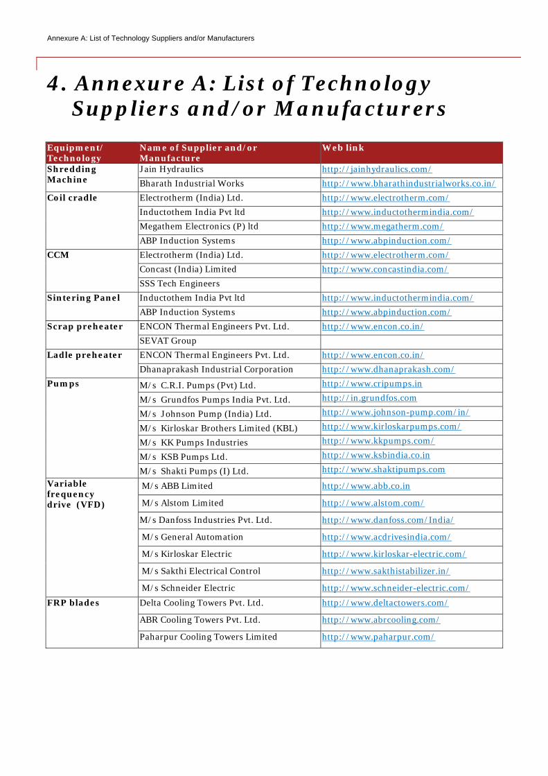
Annexure A: List of Technology Suppliers and/or Manufacturers
4. Annexure A: List of Technology Suppliers and/or Manufacturers
Equipment/ Technology
Name of Supplier and/or Manufacture
Web link
Shredding Machine
Jain Hydraulics http://jainhydraulics.com/ Bharath Industrial Works http://www.bharathindustrialworks.co.in/
Coil cradle Electrotherm (India) Ltd. http://www.electrotherm.com/ Inductothem India Pvt ltd http://www.inductothermindia.com/ Megathem Electronics (P) ltd http://www.megatherm.com/ ABP Induction Systems http://www.abpinduction.com/
CCM Electrotherm (India) Ltd. http://www.electrotherm.com/ Concast (India) Limited http://www.concastindia.com/ SSS Tech Engineers
Sintering Panel Inductothem India Pvt ltd http://www.inductothermindia.com/ ABP Induction Systems http://www.abpinduction.com/
Scrap preheater ENCON Thermal Engineers Pvt. Ltd. http://www.encon.co.in/ SEVAT Group
Ladle preheater ENCON Thermal Engineers Pvt. Ltd. http://www.encon.co.in/ Dhanaprakash Industrial Corporation http://www.dhanaprakash.com/
Pumps M/s C.R.I. Pumps (Pvt) Ltd. http://www.cripumps.in
M/s Grundfos Pumps India Pvt. Ltd. http://in.grundfos.com
M/s Johnson Pump (India) Ltd. http://www.johnson-pump.com/in/
M/s Kirloskar Brothers Limited (KBL) http://www.kirloskarpumps.com/
M/s KK Pumps Industries http://www.kkpumps.com/
M/s KSB Pumps Ltd. http://www.ksbindia.co.in
M/s Shakti Pumps (I) Ltd. http://www.shaktipumps.com Variable frequency drive (VFD)
M/s ABB Limited http://www.abb.co.in
M/s Alstom Limited http://www.alstom.com/
M/s Danfoss Industries Pvt. Ltd. http://www.danfoss.com/India/
M/s General Automation http://www.acdrivesindia.com/
M/s Kirloskar Electric http://www.kirloskar-electric.com/
M/s Sakthi Electrical Control http://www.sakthistabilizer.in/
M/s Schneider Electric http://www.schneider-electric.com/
FRP blades Delta Cooling Towers Pvt. Ltd. http://www.deltactowers.com/
ABR Cooling Towers Pvt. Ltd. http://www.abrcooling.com/
Paharpur Cooling Towers Limited http://www.paharpur.com/

Insert Header Field [Status]
Compendium of energy efficient technology measures for secondary steel electric induction furnace (EIF) sector - PwC 40
Disclaimer This publication has been prepared for general guidance on matters of interest only, and does not constitute professional advice. You should not act upon the information contained in this publication without obtaining specific professional advice. No representation or warranty (express or implied) is given as to the accuracy or completeness of the information contained in this publication, and, to the extent permitted by law, PricewaterhouseCoopers India Private Ltd., its members, employees and agents do not accept or assume any liability, responsibility or duty of care for any consequences of you or anyone else acting, or refraining to act, in reliance on the information contained in this publication or for any decision based on it. © 2014 PricewaterhouseCoopers India Private Ltd. All rights reserved. In this document, “PwC” refers to PricewaterhouseCoopers India Private Ltd., which is a member firm of PricewaterhouseCoopers International Limited, each member firm of which is a separate legal entity.


![[ITIL SYSTEM METHODOL OGY ]](https://img.pdfslide.net/doc/110x75/624cd347964d7328d919e9f8/itil-system-methodol-ogy-.jpg)