Embed Size (px)
Citation preview
Compensating and Enhancing Voltage Quality in Electrical
Distribution Systems Using Dynamic Voltage Restorer Based on
Synchronous Reference Frame Theory
Hamid Karimi1, Mohsen Simab1*, Mehdi Nafar1
1 Department of Electrical Engineering, Marvdasht Branch,
Islamic Azad University, Marvdasht, Iran.
Received: 14-Feb-2020, Revised: 22-Mar-2020, Accepted: 26-Mar-2020.
Abstract
One of the common problems of power quality is the occurrence of voltage sags due to different
types of balanced and unbalanced short-circuit faults in electrical distribution systems. Dynamic
Voltage Restorer (DVR) is the most effective equipment used for voltage recovery in power
distribution systems and it injects voltage in series with line voltage for voltage recovery. In this
paper, the structure and general components of this equipment are presented. In addition, by
applying a control scheme based on Synchronous Reference Frame Theory (SRFT) in its control
system, the effective role of this equipment in compensating and maintaining the voltage of a
power distribution system under the occurrence of balanced three-phase short-circuit fault and
unbalanced single-phase to ground short-circuit fault is investigated and analyzed using
Simulink/Matlab software.
Keywords: Short Circuit Fault, Power Quality Improvement, Voltage Sag, Dynamic Voltage
Restorer (DVR), Synchronous Reference Frame Theory (SRFT).
1. INTRODUCTION
Researches show that the equipment
expanded in the last two decades is highly
sensitive to the quality of the supply, and
large industrial consumers have reported a
large number of
major economic losses caused by the decline
in the power quality. One of the most
important problems in the power quality of
power distribution systems is the occurrence
of voltage sags, which is one of the most
important challenges for electricity
distribution companies in respect of *Corresponding Authors Email:
Signal Processing and Renewable Energy
June 2020, (pp. 53-72)
ISSN: 2588-7327
eISSN: 2588-7335
54 Karimi, Simab, Nafar. Compensating and Enhancing Voltage …
advanced industries. One of the causes of
voltage sag is the occurrence of various
short-circuit faults in the power distribution
system [1].
Custom Power or D-FACTS devices
have been introduced as equipment based on
power electronic for controlling distribution
systems and improving the power quality of
electrical distribution systems. The structure
and topology of some of these devices are
presented in [2-5]. One type of device used
to correct voltage Sags in distribution
systems is Dynamic Voltage Restorer
(DVR) which the components and topology
of this device are introduced in [6-11]. The
purpose of DVR is to protect sensitive loads
from system disturbances. In the event of a
fault, this equipment injects a voltage equal
to the difference between the pre-fault
voltage and the voltage during the fault by
supplying the active power required from
the DC power supply and the reactive
power, and maintaining the load voltage in
the range prior to the fault. When the
voltage is injected into the distribution
feeder in series with the compensator, the
voltage is kept constant in the load terminals
against the power quality disturbances on
the source side. Quality of the compensation
and quality of the injected voltage depend
on the type of control used in this
compensator. In this paper, the control
technique based on synchronous reference
frame theory, which is one of the most
effective control methods for compensators,
is used. Furthermore, by applying this
control scheme to the DVR structure, the
effective role of this equipment in
compensating voltage of a power
distribution system is examined and
analyzed in the event of short circuit faults.
The aim of the control scheme is to
maintain constant voltage magnitude at the
point where a sensitive load is connected,
under system disturbances. The general
requirement of a control scheme is to obtain
an ac waveform with minimum total
harmonic distortion (THD) and best
dynamic response against supply and load
disturbance when the DVR is operated for
voltage sag compensation. There are
different control techniques being used for
the calculation of request voltage for
compensator. In [12-14]. A control scheme
based on RMS value of voltage has been
implemented to control the two-level VSC
used in the DVR and D-STATCOM. This
control system only measures the RMS
voltage at the load point. Using RMS value
calculation of the voltage to analyze the sags
does not give fast and suitable response and
also it does not give accurate results and in
during compensation, it cannot recover load
instantaneous voltage accurately. Also,
using this technique will significantly
increase the total harmonic distortion (THD)
of the load compensated voltage [14]. In
[15, 16], the difference between the
reference voltage and the voltage injected by
compensator is used to produce the load
rated voltage. When the source voltage is
within the nominal range, the DVR always
injects a small amount of voltage into the
system. Due to this problem, applying this
method to the DVR control system may
result in the failure to determine the exact
voltage needed to compensate during the
event of fault in the system and there may
always be some deviation in the injected
Signal Processing and Renewable Energy, June 2020 55
voltage. As well as the problem outlined, the
system does not respond well when
compensating for different voltage
disturbances. Another technique used to
control this compensator and other similar
compensators is the instantaneous reactive
power theory (p-q technique) [17-20]. One
of the disadvantages of this method is that
the unbalanced voltage or current results in
incorrect calculation of the reference signals
are produced by the compensator [20].
Hence, for proper voltage sag
compensation, it is necessary to derive
suitable control scheme for inverter
switching. In this paper, the control
technique based on synchronous reference
frame theory, which is one of the most
effective control methods for compensators,
is used and by applying this control scheme
to the DVR structure, the effective role of
this equipment in compensating voltage of a
power distribution system is examined and
analyzed in the event of short circuit faults.
Also, the VSC switching strategy is based
on a sinusoidal PWM technique which
offers simplicity and good response. The
proposed compensator amends both
balanced and unbalanced voltage sags and
injects the appropriate voltage component to
correct any voltage sag rapidly and to keep
the load voltage balanced and constant at the
nominal value.
2. STRUCTURE AND COMPONENTS
OF THE DYNAMIC VOLTAGE
RESTORER (DVR)
Dynamic voltage restorer is used to protect
loads and to prevent disturbances on the
supply side from reaching sensitive loads.
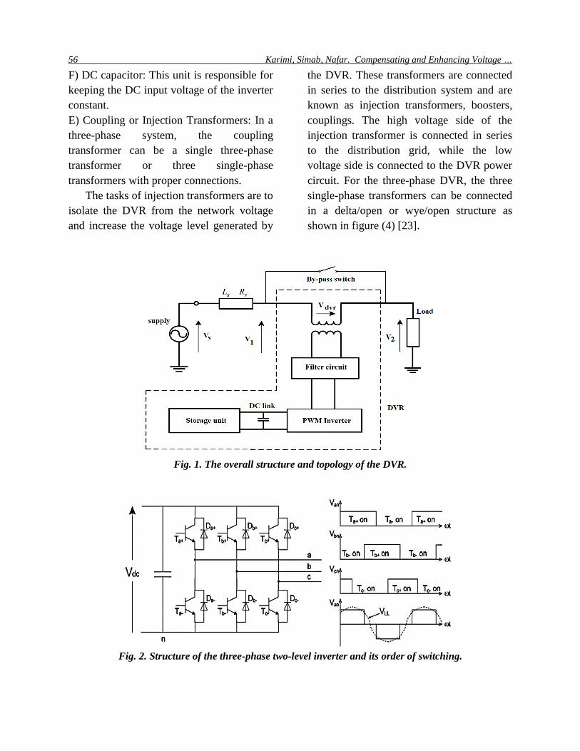
The overall structure and topology of this
device is shown in Fig. 1 [22].
The main components of this device are
as follows [23, 26]:
A) Power Storage Unit: This unit is
responsible for DC power storage and thus
provides the active power required for DVR
compensation.
B) Inverter or voltage source converter
(VSC): A pulse-width modulation inverter is
generally used. The main task of the DC
voltage converter is to convert the DC
voltage provided by the AC to AC voltage
source.
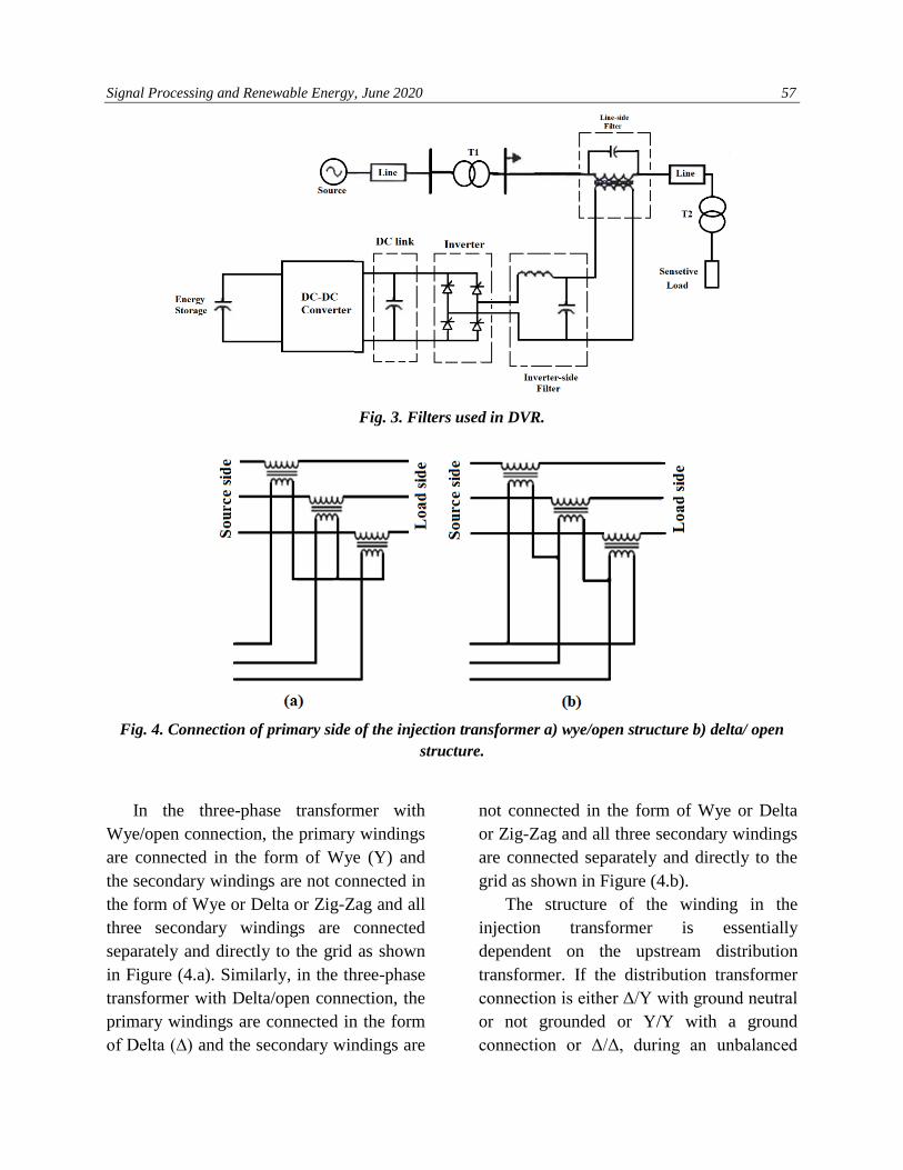
Often three-phase two-level inverters are
used. Each leg is switched according to
pulse width modulation. In the case of
switching with the main frequency
switching, the switches are ON for a 180-
degrees period with a 50% duty cycle. The
structure of the inverter, switching and
output waveforms in the switching mode
with the main frequency are shown in Figure
(2).
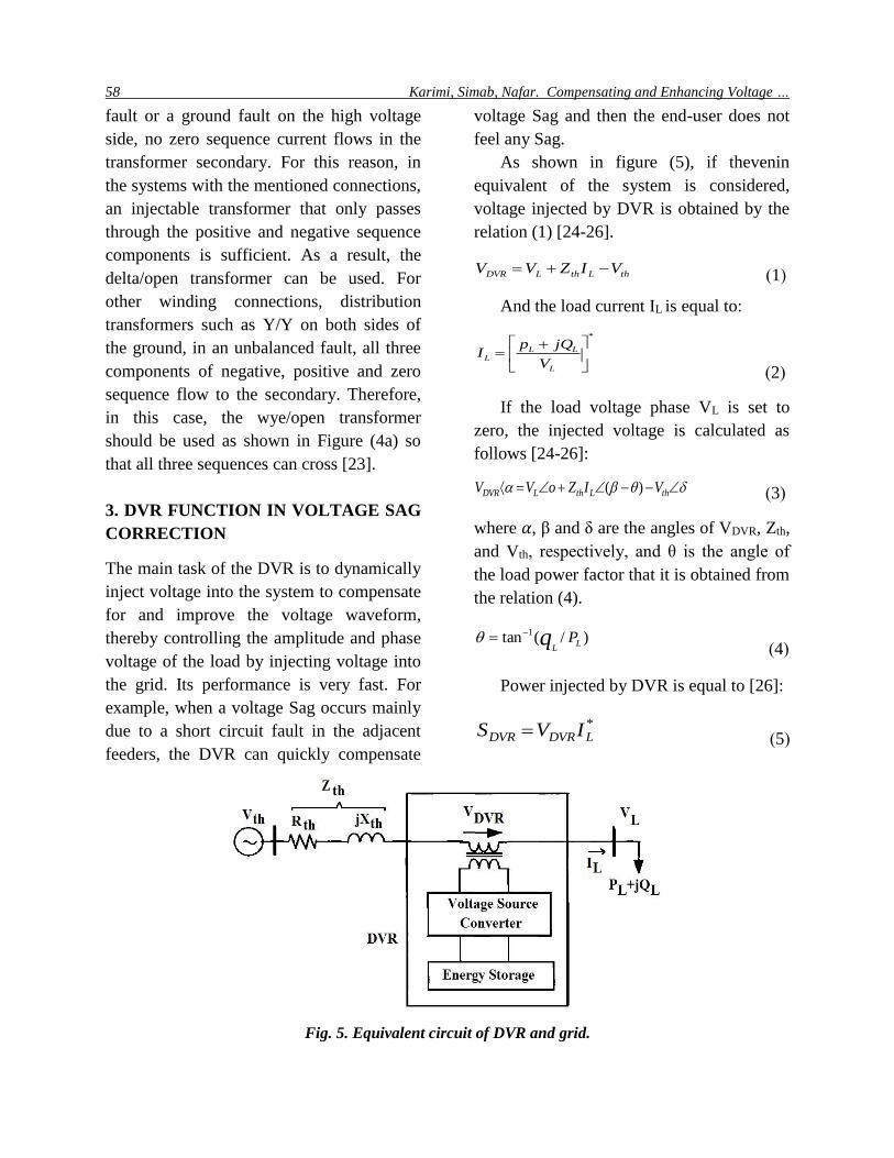
C) Passive Filter: Passive filters are used to
convert the PWM pulse waveform to a
sinusoidal waveform. By inserting the filter
at the inverter output, the higher order
harmonic components produced by the DC
to AC conversion are eliminated in the
voltage source inverter [23]. As shown in
Figure (3), these filters can be mounted
either on the high voltage side or on the low
voltage side of the injection transformer.
D) Bypass switch: A bypass switch is used
to protect the inverter from high currents
when a fault or short circuit occurs
downstream.
56 Karimi, Simab, Nafar. Compensating and Enhancing Voltage …
F) DC capacitor: This unit is responsible for
keeping the DC input voltage of the inverter
constant.
E) Coupling or Injection Transformers: In a
three-phase system, the coupling
transformer can be a single three-phase
transformer or three single-phase
transformers with proper connections.
The tasks of injection transformers are to
isolate the DVR from the network voltage
and increase the voltage level generated by
the DVR. These transformers are connected
in series to the distribution system and are
known as injection transformers, boosters,
couplings. The high voltage side of the
injection transformer is connected in series
to the distribution grid, while the low
voltage side is connected to the DVR power
circuit. For the three-phase DVR, the three
single-phase transformers can be connected
in a delta/open or wye/open structure as
shown in figure (4) [23].
Fig. 1. The overall structure and topology of the DVR.
Fig. 2. Structure of the three-phase two-level inverter and its order of switching.
Signal Processing and Renewable Energy, June 2020 57
Fig. 3. Filters used in DVR.
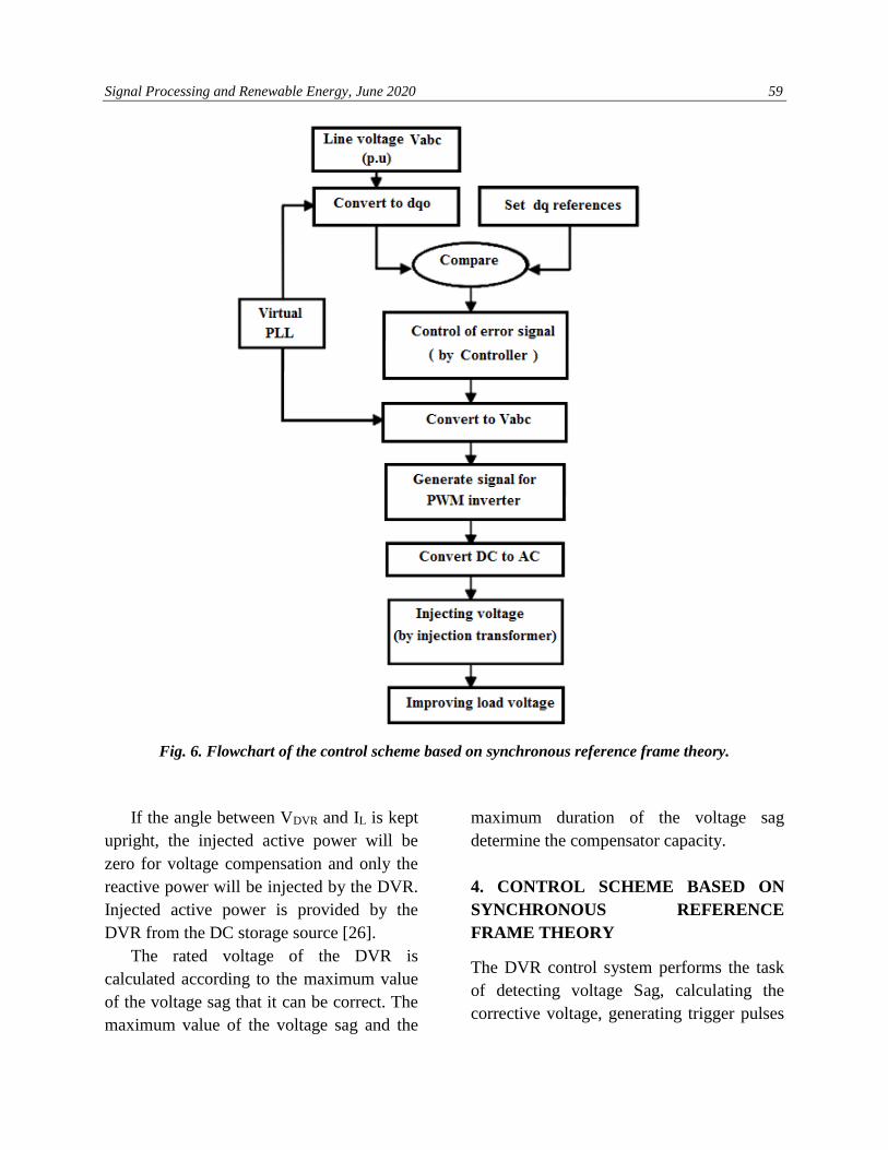
Fig. 4. Connection of primary side of the injection transformer a) wye/open structure b) delta/ open
structure.
In the three-phase transformer with
Wye/open connection, the primary windings
are connected in the form of Wye (Y) and
the secondary windings are not connected in
the form of Wye or Delta or Zig-Zag and all
three secondary windings are connected
separately and directly to the grid as shown
in Figure (4.a). Similarly, in the three-phase
transformer with Delta/open connection, the
primary windings are connected in the form
of Delta (∆) and the secondary windings are
not connected in the form of Wye or Delta
or Zig-Zag and all three secondary windings
are connected separately and directly to the
grid as shown in Figure (4.b).
The structure of the winding in the
injection transformer is essentially
dependent on the upstream distribution
transformer. If the distribution transformer
connection is either Δ/Y with ground neutral
or not grounded or Y/Y with a ground
connection or Δ/Δ, during an unbalanced
58 Karimi, Simab, Nafar. Compensating and Enhancing Voltage …
fault or a ground fault on the high voltage
side, no zero sequence current flows in the
transformer secondary. For this reason, in
the systems with the mentioned connections,
an injectable transformer that only passes
through the positive and negative sequence
components is sufficient. As a result, the
delta/open transformer can be used. For
other winding connections, distribution
transformers such as Y/Y on both sides of
the ground, in an unbalanced fault, all three
components of negative, positive and zero
sequence flow to the secondary. Therefore,
in this case, the wye/open transformer
should be used as shown in Figure (4a) so
that all three sequences can cross [23].
3. DVR FUNCTION IN VOLTAGE SAG
CORRECTION
The main task of the DVR is to dynamically
inject voltage into the system to compensate
for and improve the voltage waveform,
thereby controlling the amplitude and phase
voltage of the load by injecting voltage into
the grid. Its performance is very fast. For
example, when a voltage Sag occurs mainly
due to a short circuit fault in the adjacent
feeders, the DVR can quickly compensate
voltage Sag and then the end-user does not
feel any Sag.
As shown in figure (5), if thevenin
equivalent of the system is considered,
voltage injected by DVR is obtained by the
relation (1) [24-26].
(1 ) thLthLDVR VIZVV −+=
And the load current IL is equal to:
(2 )
*
+=
L
LLL
V
jQpI
If the load voltage phase VL is set to
zero, the injected voltage is calculated as
follows [24-26]:
(3) −−+= thLthLDVR VIZoVV )(
where 𝛼, β and δ are the angles of VDVR, Zth,
and Vth, respectively, and θ is the angle of
the load power factor that it is obtained from
the relation (4).
(4) )/(tan 1
LL
Pq−=
Power injected by DVR is equal to [26]:
(5) *LDVRDVR IVS =
Fig. 5. Equivalent circuit of DVR and grid.
Signal Processing and Renewable Energy, June 2020 59
Fig. 6. Flowchart of the control scheme based on synchronous reference frame theory.
If the angle between VDVR and IL is kept
upright, the injected active power will be
zero for voltage compensation and only the
reactive power will be injected by the DVR.
Injected active power is provided by the
DVR from the DC storage source [26].
The rated voltage of the DVR is
calculated according to the maximum value
of the voltage sag that it can be correct. The
maximum value of the voltage sag and the
maximum duration of the voltage sag
determine the compensator capacity.
4. CONTROL SCHEME BASED ON
SYNCHRONOUS REFERENCE
FRAME THEORY
The DVR control system performs the task
of detecting voltage Sag, calculating the
corrective voltage, generating trigger pulses
60 Karimi, Simab, Nafar. Compensating and Enhancing Voltage …
for voltage source converter and correcting
any abnormal conditions in the series
voltage injection, and terminating the trigger
pulses when the fault is resolved. There are
many control methods for DVR control. One
of the best and most effective of the methods
being the Synchronous Reference Frame
(SRFT) Based technique or dq0 technique,
in which phase lock loop (PLL) and park
conversion or dqo are used to control DVR
[21, 27, 28]. Figure 6 shows the flowchart of
the synchronous reference frame-based
technique for detecting voltage Sag.
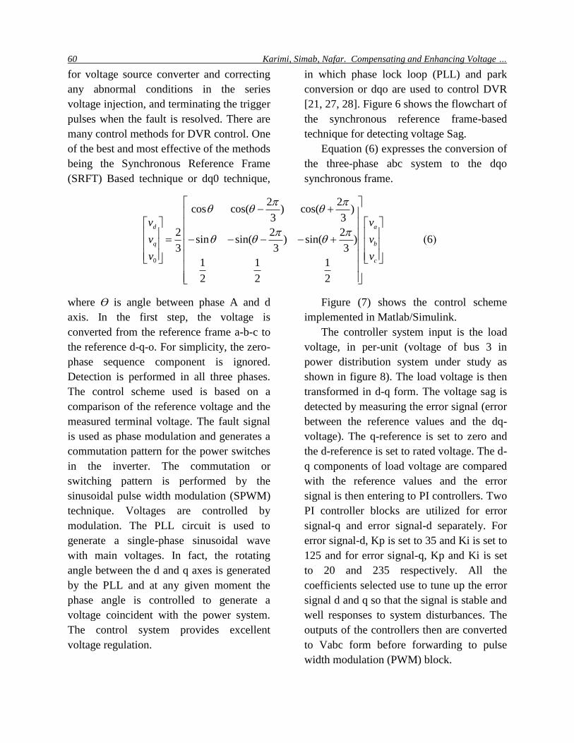
Equation (6) expresses the conversion of
the three-phase abc system to the dqo
synchronous frame.
(6)
0
2 2cos cos( ) cos( )
3 3
2 2 2sin sin( ) sin( )
3 3 3
1 1 1
2 2 2
d a
q b
c
v v
v v
v v
− +
= − − − − +
where ϴ is angle between phase A and d
axis. In the first step, the voltage is
converted from the reference frame a-b-c to
the reference d-q-o. For simplicity, the zero-
phase sequence component is ignored.
Detection is performed in all three phases.
The control scheme used is based on a
comparison of the reference voltage and the
measured terminal voltage. The fault signal
is used as phase modulation and generates a
commutation pattern for the power switches
in the inverter. The commutation or
switching pattern is performed by the
sinusoidal pulse width modulation (SPWM)
technique. Voltages are controlled by
modulation. The PLL circuit is used to
generate a single-phase sinusoidal wave
with main voltages. In fact, the rotating
angle between the d and q axes is generated
by the PLL and at any given moment the
phase angle is controlled to generate a
voltage coincident with the power system.
The control system provides excellent
voltage regulation.
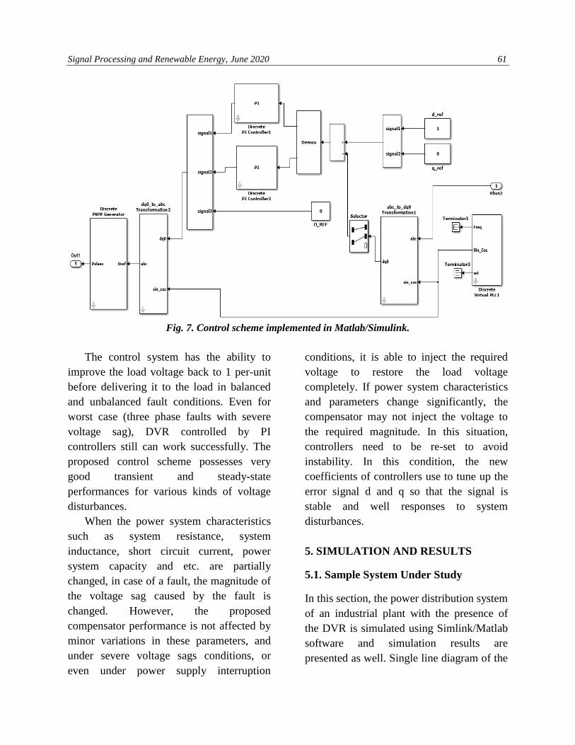
Figure (7) shows the control scheme
implemented in Matlab/Simulink.
The controller system input is the load
voltage, in per-unit (voltage of bus 3 in
power distribution system under study as
shown in figure 8). The load voltage is then
transformed in d-q form. The voltage sag is
detected by measuring the error signal (error
between the reference values and the dq-
voltage). The q-reference is set to zero and
the d-reference is set to rated voltage. The d-
q components of load voltage are compared
with the reference values and the error
signal is then entering to PI controllers. Two
PI controller blocks are utilized for error
signal-q and error signal-d separately. For
error signal-d, Kp is set to 35 and Ki is set to
125 and for error signal-q, Kp and Ki is set
to 20 and 235 respectively. All the
coefficients selected use to tune up the error
signal d and q so that the signal is stable and
well responses to system disturbances. The
outputs of the controllers then are converted
to Vabc form before forwarding to pulse
width modulation (PWM) block.
Signal Processing and Renewable Energy, June 2020 61
Fig. 7. Control scheme implemented in Matlab/Simulink.
The control system has the ability to
improve the load voltage back to 1 per-unit
before delivering it to the load in balanced
and unbalanced fault conditions. Even for
worst case (three phase faults with severe
voltage sag), DVR controlled by PI
controllers still can work successfully. The
proposed control scheme possesses very
good transient and steady-state
performances for various kinds of voltage
disturbances.
When the power system characteristics
such as system resistance, system
inductance, short circuit current, power
system capacity and etc. are partially
changed, in case of a fault, the magnitude of
the voltage sag caused by the fault is
changed. However, the proposed
compensator performance is not affected by
minor variations in these parameters, and
under severe voltage sags conditions, or
even under power supply interruption
conditions, it is able to inject the required
voltage to restore the load voltage
completely. If power system characteristics
and parameters change significantly, the
compensator may not inject the voltage to
the required magnitude. In this situation,
controllers need to be re-set to avoid
instability. In this condition, the new
coefficients of controllers use to tune up the
error signal d and q so that the signal is
stable and well responses to system
disturbances.
5. SIMULATION AND RESULTS
5.1. Sample System Under Study
In this section, the power distribution system
of an industrial plant with the presence of
the DVR is simulated using Simlink/Matlab
software and simulation results are
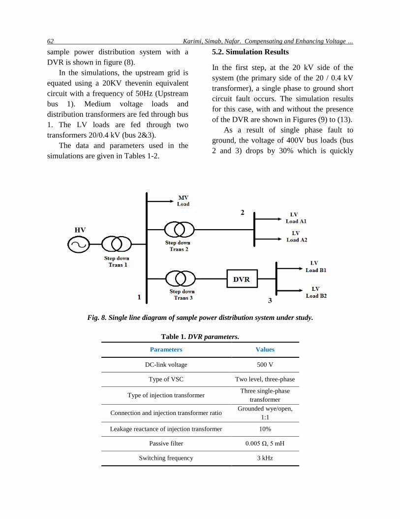
presented as well. Single line diagram of the
62 Karimi, Simab, Nafar. Compensating and Enhancing Voltage …
sample power distribution system with a
DVR is shown in figure (8).
In the simulations, the upstream grid is
equated using a 20KV thevenin equivalent
circuit with a frequency of 50Hz (Upstream
bus 1). Medium voltage loads and
distribution transformers are fed through bus
1. The LV loads are fed through two
transformers 20/0.4 kV (bus 2&3).
The data and parameters used in the
simulations are given in Tables 1-2.
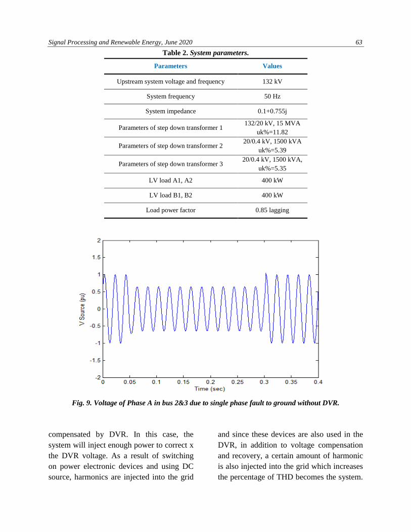
5.2. Simulation Results
In the first step, at the 20 kV side of the
system (the primary side of the 20 / 0.4 kV
transformer), a single phase to ground short
circuit fault occurs. The simulation results
for this case, with and without the presence
of the DVR are shown in Figures (9) to (13).
As a result of single phase fault to
ground, the voltage of 400V bus loads (bus
2 and 3) drops by 30% which is quickly
Fig. 8. Single line diagram of sample power distribution system under study.
Table 1. DVR parameters.
Values Parameters
500 V DC-link voltage
Two level, three-phase Type of VSC
Three single-phase
transformer Type of injection transformer
Grounded wye/open,
1:1 Connection and injection transformer ratio
10% Leakage reactance of injection transformer
0.005 Ω, 5 mH Passive filter
3 kHz Switching frequency
Signal Processing and Renewable Energy, June 2020 63
Table 2. System parameters.
Values Parameters
132 kV Upstream system voltage and frequency
50 Hz System frequency
0.1+0.755j System impedance
132/20 kV, 15 MVA
uk%=11.82 Parameters of step down transformer 1
20/0.4 kV, 1500 kVA
uk%=5.39 Parameters of step down transformer 2
20/0.4 kV, 1500 kVA,
uk%=5.35 Parameters of step down transformer 3
400 kW LV load A1, A2
400 kW LV load B1, B2
0.85 lagging Load power factor
Fig. 9. Voltage of Phase A in bus 2&3 due to single phase fault to ground without DVR.
compensated by DVR. In this case, the
system will inject enough power to correct x
the DVR voltage. As a result of switching
on power electronic devices and using DC
source, harmonics are injected into the grid
and since these devices are also used in the
DVR, in addition to voltage compensation
and recovery, a certain amount of harmonic
is also injected into the grid which increases
the percentage of THD becomes the system.
64 Karimi, Simab, Nafar. Compensating and Enhancing Voltage …
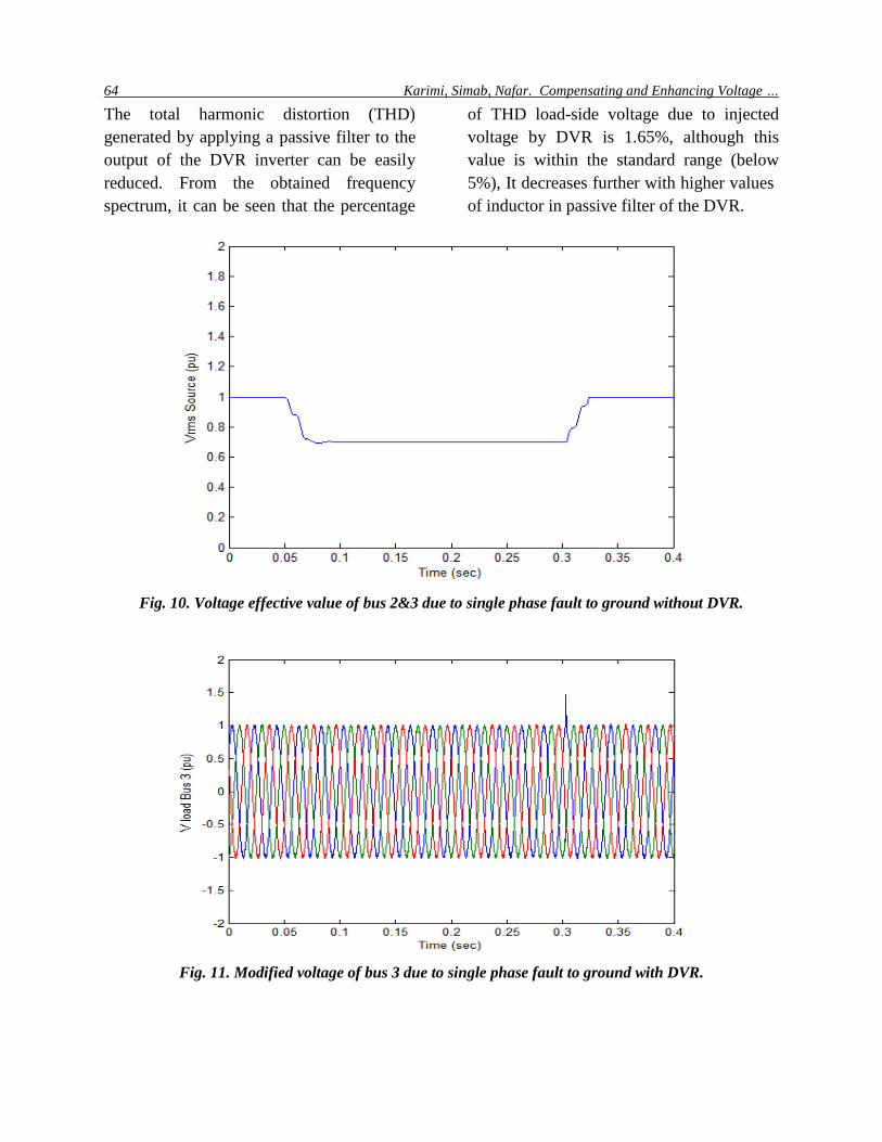
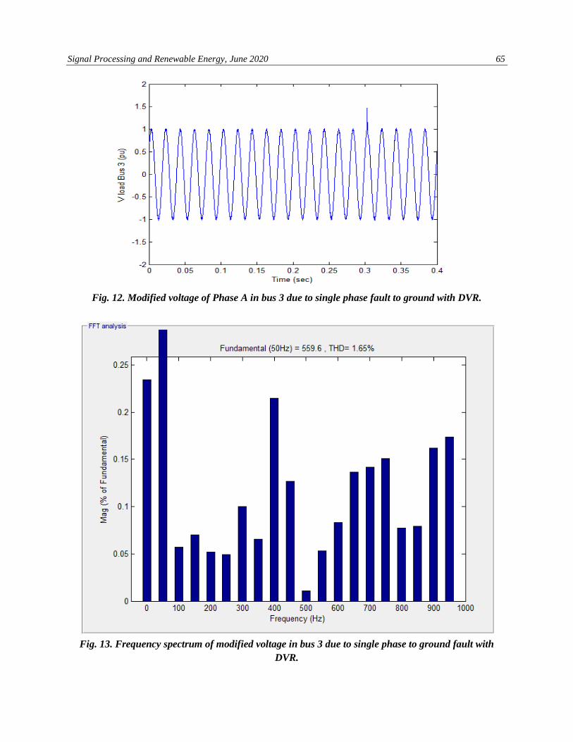
The total harmonic distortion (THD)
generated by applying a passive filter to the
output of the DVR inverter can be easily
reduced. From the obtained frequency
spectrum, it can be seen that the percentage
of THD load-side voltage due to injected
voltage by DVR is 1.65%, although this
value is within the standard range (below
5%), It decreases further with higher values
of inductor in passive filter of the DVR.
Fig. 10. Voltage effective value of bus 2&3 due to single phase fault to ground without DVR.
Fig. 11. Modified voltage of bus 3 due to single phase fault to ground with DVR.
Signal Processing and Renewable Energy, June 2020 65
Fig. 12. Modified voltage of Phase A in bus 3 due to single phase fault to ground with DVR.
Fig. 13. Frequency spectrum of modified voltage in bus 3 due to single phase to ground fault with
DVR.
66 Karimi, Simab, Nafar. Compensating and Enhancing Voltage …
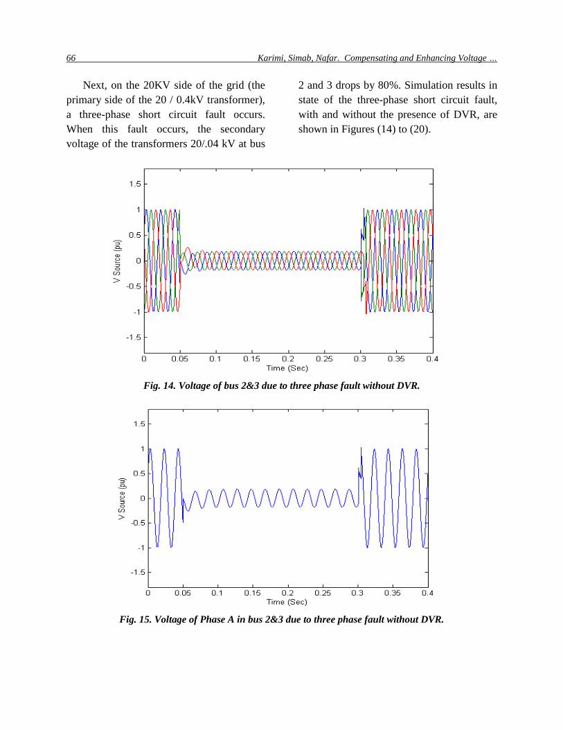
Next, on the 20KV side of the grid (the
primary side of the 20 / 0.4kV transformer),
a three-phase short circuit fault occurs.
When this fault occurs, the secondary
voltage of the transformers 20/.04 kV at bus
2 and 3 drops by 80%. Simulation results in
state of the three-phase short circuit fault,
with and without the presence of DVR, are
shown in Figures (14) to (20).
Fig. 14. Voltage of bus 2&3 due to three phase fault without DVR.
Fig. 15. Voltage of Phase A in bus 2&3 due to three phase fault without DVR.
Signal Processing and Renewable Energy, June 2020 67
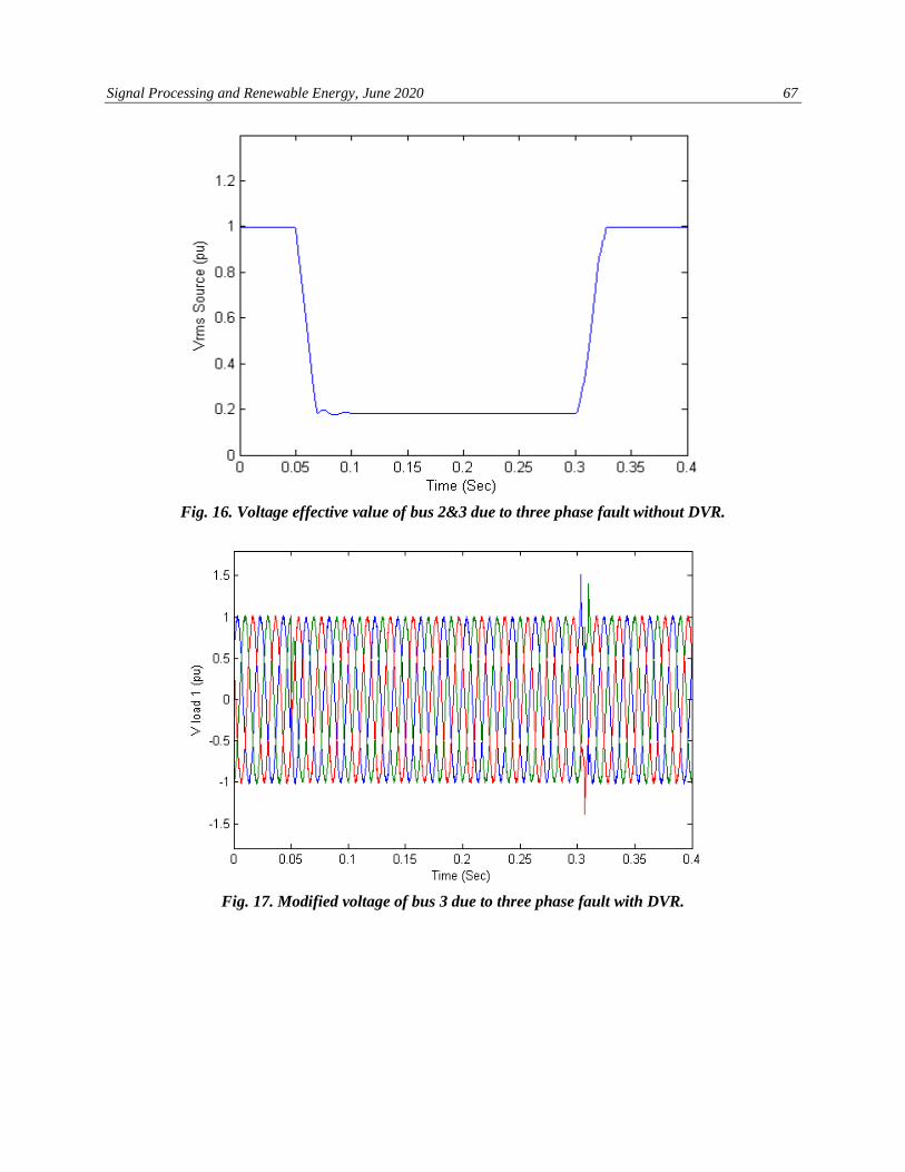
Fig. 16. Voltage effective value of bus 2&3 due to three phase fault without DVR.
Fig. 17. Modified voltage of bus 3 due to three phase fault with DVR.
68 Karimi, Simab, Nafar. Compensating and Enhancing Voltage …
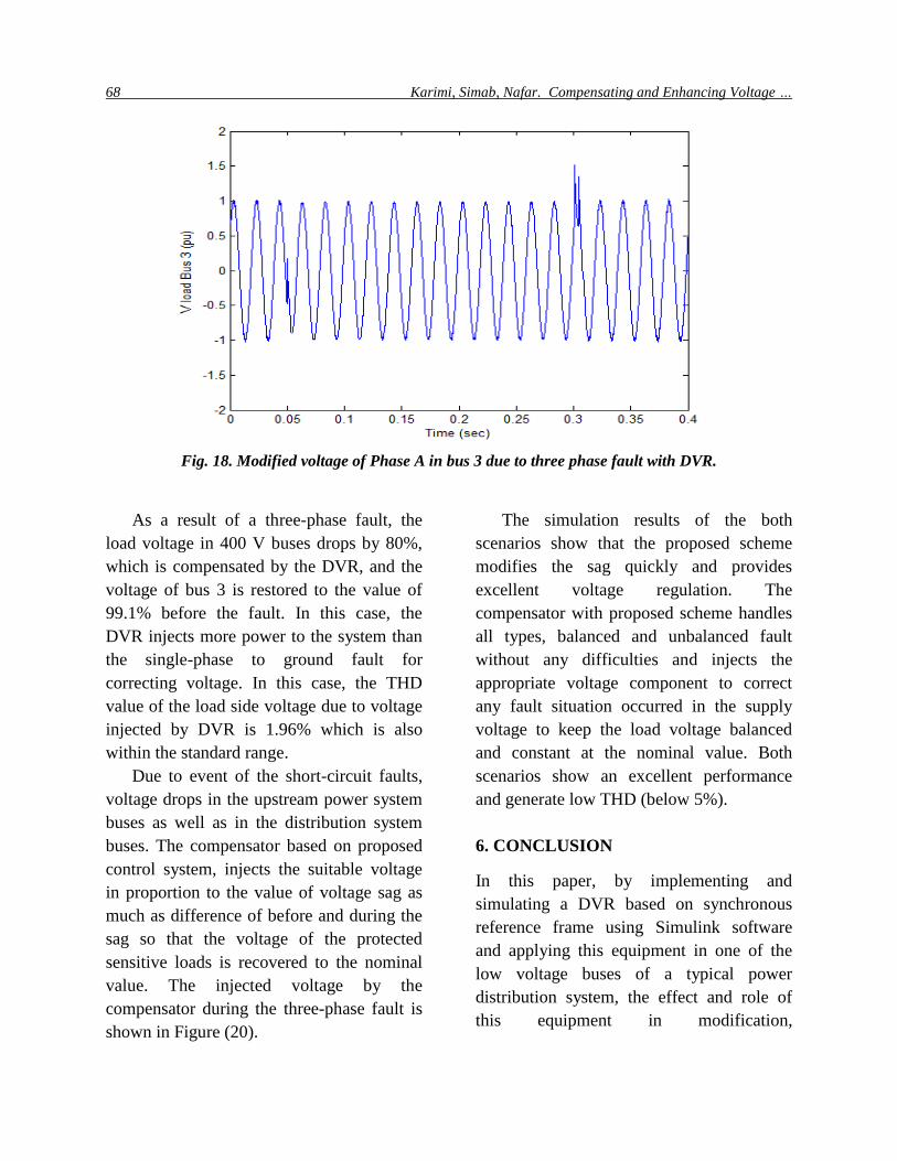
Fig. 18. Modified voltage of Phase A in bus 3 due to three phase fault with DVR.
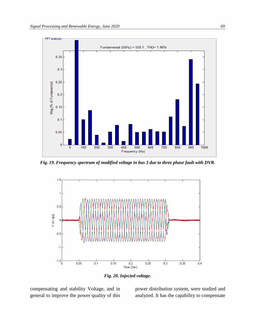
As a result of a three-phase fault, the
load voltage in 400 V buses drops by 80%,
which is compensated by the DVR, and the
voltage of bus 3 is restored to the value of
99.1% before the fault. In this case, the
DVR injects more power to the system than
the single-phase to ground fault for
correcting voltage. In this case, the THD
value of the load side voltage due to voltage
injected by DVR is 1.96% which is also
within the standard range.
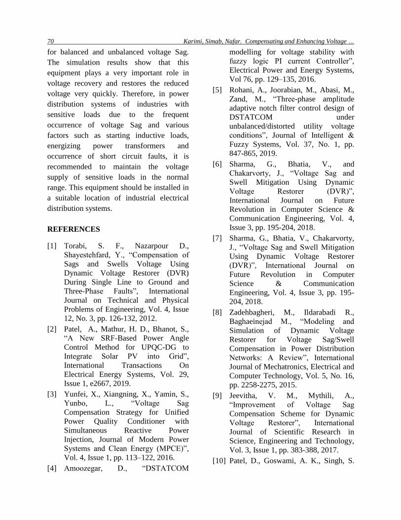
Due to event of the short-circuit faults,
voltage drops in the upstream power system
buses as well as in the distribution system
buses. The compensator based on proposed
control system, injects the suitable voltage
in proportion to the value of voltage sag as
much as difference of before and during the
sag so that the voltage of the protected
sensitive loads is recovered to the nominal
value. The injected voltage by the
compensator during the three-phase fault is
shown in Figure (20).
The simulation results of the both
scenarios show that the proposed scheme
modifies the sag quickly and provides
excellent voltage regulation. The
compensator with proposed scheme handles
all types, balanced and unbalanced fault
without any difficulties and injects the
appropriate voltage component to correct
any fault situation occurred in the supply
voltage to keep the load voltage balanced
and constant at the nominal value. Both
scenarios show an excellent performance
and generate low THD (below 5%).
6. CONCLUSION
In this paper, by implementing and
simulating a DVR based on synchronous
reference frame using Simulink software
and applying this equipment in one of the
low voltage buses of a typical power
distribution system, the effect and role of
this equipment in modification,
Signal Processing and Renewable Energy, June 2020 69
Fig. 19. Frequency spectrum of modified voltage in bus 3 due to three phase fault with DVR.
Fig. 20. Injected voltage.
compensating and stability Voltage, and in
general to improve the power quality of this
power distribution system, were studied and
analyzed. It has the capability to compensate
70 Karimi, Simab, Nafar. Compensating and Enhancing Voltage …
for balanced and unbalanced voltage Sag.
The simulation results show that this
equipment plays a very important role in
voltage recovery and restores the reduced
voltage very quickly. Therefore, in power
distribution systems of industries with
sensitive loads due to the frequent
occurrence of voltage Sag and various
factors such as starting inductive loads,
energizing power transformers and
occurrence of short circuit faults, it is
recommended to maintain the voltage
supply of sensitive loads in the normal
range. This equipment should be installed in
a suitable location of industrial electrical
distribution systems.
REFERENCES
[1] Torabi, S. F., Nazarpour D.,
Shayestehfard, Y., “Compensation of
Sags and Swells Voltage Using
Dynamic Voltage Restorer (DVR)
During Single Line to Ground and
Three-Phase Faults”, International
Journal on Technical and Physical
Problems of Engineering, Vol. 4, Issue
12, No. 3, pp. 126-132, 2012.
[2] Patel, A., Mathur, H. D., Bhanot, S.,
“A New SRF-Based Power Angle
Control Method for UPQC-DG to
Integrate Solar PV into Grid”,
International Transactions On
Electrical Energy Systems, Vol. 29,
Issue 1, e2667, 2019.
[3] Yunfei, X., Xiangning, X., Yamin, S.,
Yunbo, L., “Voltage Sag
Compensation Strategy for Unified
Power Quality Conditioner with
Simultaneous Reactive Power
Injection, Journal of Modern Power
Systems and Clean Energy (MPCE)”,
Vol. 4, Issue 1, pp. 113–122, 2016.
[4] Amoozegar, D., “DSTATCOM
modelling for voltage stability with
fuzzy logic PI current Controller”,
Electrical Power and Energy Systems,
Vol 76, pp. 129–135, 2016.
[5] Rohani, A., Joorabian, M., Abasi, M.,
Zand, M., “Three-phase amplitude
adaptive notch filter control design of
DSTATCOM under
unbalanced/distorted utility voltage
conditions”, Journal of Intelligent &
Fuzzy Systems, Vol. 37, No. 1, pp.
847-865, 2019.
[6] Sharma, G., Bhatia, V., and
Chakarvorty, J., “Voltage Sag and
Swell Mitigation Using Dynamic
Voltage Restorer (DVR)”,
International Journal on Future
Revolution in Computer Science &
Communication Engineering, Vol. 4,
Issue 3, pp. 195-204, 2018.
[7] Sharma, G., Bhatia, V., Chakarvorty,
J., “Voltage Sag and Swell Mitigation
Using Dynamic Voltage Restorer
(DVR)”, International Journal on
Future Revolution in Computer
Science & Communication
Engineering, Vol. 4, Issue 3, pp. 195-
204, 2018.
[8] Zadehbagheri, M., Ildarabadi R.,
Baghaeinejad M., “Modeling and
Simulation of Dynamic Voltage
Restorer for Voltage Sag/Swell
Compensation in Power Distribution
Networks: A Review”, International
Journal of Mechatronics, Electrical and
Computer Technology, Vol. 5, No. 16,
pp. 2258-2275, 2015.
[9] Jeevitha, V. M., Mythili, A.,
“Improvement of Voltage Sag
Compensation Scheme for Dynamic
Voltage Restorer”, International
Journal of Scientific Research in
Science, Engineering and Technology,
Vol. 3, Issue 1, pp. 383-388, 2017.
[10] Patel, D., Goswami, A. K., Singh, S.
Signal Processing and Renewable Energy, June 2020 71
K., “Voltage Sag Mitigation in an
Indian Distribution System Using
Dynamic Voltage Restorer,” Electrical
Power and Energy Systems, Vol. 71,
pp. 231-241, 2015.
[11] Ramasamy M., Thangavel, S.,
“Optimal Utilization of PV Solar
System as DVR (PV-DVR) for a
Residence or Small Industry”, Journal
of Applied Science and Engineering,
Vol. 16, No. 3, pp. 295-304, 2013.
[12] Tiwari, H. P., Gupta, S. K., “Dynamic
voltage restorer based on load
condition”, International Journal of
Innovation, Management and
Technology, Vol. 1, No. 1, 2010.
[13] Singh, S. K., Srivastava, S. K.,
“Enhancement in Power Quality using
Dynamic Voltage Restorer (DVR) in
Distribution Network”, International
Conference on Innovations in
information Embedded and
Communication Systems (ICIIECS),
Coimbatore, pp. 1-5, 2017.
[14] Gupta, S. K., Tiwari, H. P., Pachar, R.,
“Study of Major Issues and Their
Impact on DVR System Performance”,
International Journal of Computer and
Electrical Engineering, Vol. 2, No. 1,
February, 2010.
[15] Eltamaly, A. M., Mohamed, Y. S.,
Mustafa El-Sayed, A. H., Abd
Elghaffar, A. N., “Enhancement of
Power System Quality Using PI
Control Technique with DVR for
Mitigation Voltage Sag”, Twentieth
International Middle East Power
Systems Conference (MEPCON),
Cairo University, Egypt, 2018.
[16] Ferdi, B. C., Benachaiba, S., Dehini,
R., “Adaptive PI control of dynamic
voltage restorer using fuzzy logic”,
Journal of Electrical Engineering:
Theory and Application, Vol. 1, Issue
3, p. 165-173, 2010.
[17] Singh, B., Solanki, J., “A Comparison
of Control Algorithms for
DSTATCOM”, IEEE Transactions on
Industrial Electronics, Vol. 56, No. 7,
July 2009.
[18] Bangarraju, J., Rajagopal, V.,
Jayalaxmi, A., “Implementation of
Three -Leg VSC based DVR using
IRPT Control Algorithm”, Power
Electronics (IICPE), IEEE 6th India
International Conference on
Kurukshetra, India, 8-10 Dec, 2014.
[19] Katole, Dh. N., Daigavane, M. B.,
Gawande, S. P., Daigavane, P.,
“Modified instantaneous p-q theory for
single phase DVR for mitigation of
voltage sag in case of nonlinear load”,
International Conference on Electrical
Power and Energy Systems (ICEPES)
Maulana Azad National Institute of
Technology, Bhopal, India. Dec 14-16,
2016.
[20] Jain, N., Gupta, A., “Comparison
between Two Compensation Current
Control Methods of Shunt Active
Power filter”, International Journal of
Engineering Research and General
Science, Vol. 2, Issue 5, August-
September, 2014.
[21] Jayaprakash, P., Singh, B., Kothari, D.
P., Chandra, A., Al-Haddad, K.,
“Control of Reduced-Rating Dynamic
Voltage Restorer with a Battery Energy
Storage System”, IEEE Transactions
on Industry Applications, Vol. 50, No.
2, March/April 2014.
[22] Mahdianpoor, F. M., Hooshmand, R.
A., Ataei, M., “A New Approach to
Multifunctional Dynamic Voltage
Restorer Implementation for
Emergency Control in Distribution
Systems”, IEEE Transactions on Power
Delivery, Vol. 26, No. 2, April 2011.
[23] Bayindir K., “Modeling of custom
power devices, Ph.D. Thesis”,
72 Karimi, Simab, Nafar. Compensating and Enhancing Voltage …
Department of Electrical and
Electronics Engineering, University of
Cukurova, 2006.
[24] Wahab, Sh. W., Yusof, A. M.,
“Voltage Sag and Mitigation Using
Dynamic Voltage Restorer (DVR)
System”, Elektrika- Journal of
Electrical Engineering, Vol. 8, No. 2,
pp. 32-37, 2006.
[25] Vasudevanaidu, P., Narendra Kumar,
Y., “A New Simple Modeling and
Analysis of Custom Power
Controllers”, Third International
Conference on Power Systems,
Kharagpur, India, December 27-29,
2009.
[26] Ravi Kumar, S. V., Nagaraju, S. S.,
“Simulation of DSTATCOM and DVR
in power systems”, Asian Research
Publishing Network (ARPN), Journal
of Engineering and Applied Sciences,
Vol. 2, No. 3, 2007.
[27] Salimin, R. H., Rahim, M. S. A.,
“Simulation Analysis of DVR
Performance for Voltage Sag
Mitigation”, The 5th International
Power Engineering and Optimization
Conference (PEOCO2011), Shah
Alam, Selangor, Malaysia: 6-7 June
2011.
[28] Hamza, A. H., Koliel, M. S., Eissawi,
H., Hafez, M. M., “Improvement of
Dynamic Voltage Restorer (DVR)
Using Proportional Integral (PI)
Controller for Mitigation of Voltage
Sag”, Arab Journal of Nuclear Science
and Applications, Vol. 48, No. 1, p. 44-
52, 2015.