Embed Size (px)
Citation preview
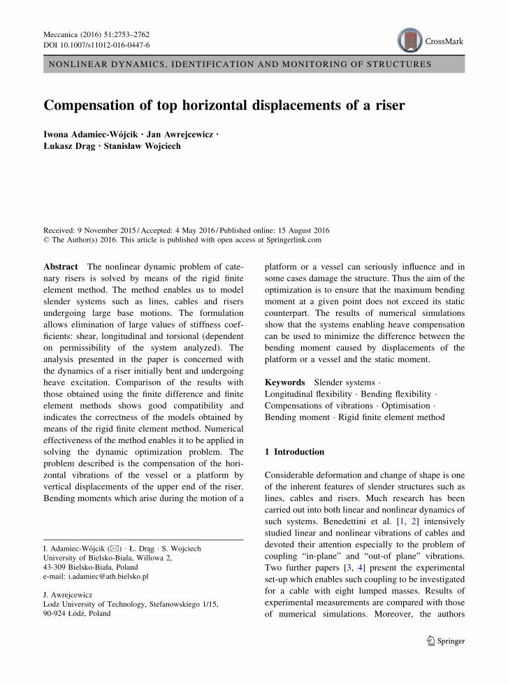
NONLINEAR DYNAMICS, IDENTIFICATION AND MONITORING OF STRUCTURES
Compensation of top horizontal displacements of a riser
Iwona Adamiec-Wójcik . Jan Awrejcewicz .
Łukasz Drąg . Stanisław Wojciech
Received: 9 November 2015 / Accepted: 4 May 2016 / Published online: 15 August 2016
© The Author(s) 2016. This article is published with open access at Springerlink.com
Abstract The nonlinear dynamic problem of cate-
nary risers is solved by means of the rigid finite
element method. The method enables us to model
slender systems such as lines, cables and risers
undergoing large base motions. The formulation
allows elimination of large values of stiffness coef-
ficients: shear, longitudinal and torsional (dependent
on permissibility of the system analyzed). The
analysis presented in the paper is concerned with
the dynamics of a riser initially bent and undergoing
heave excitation. Comparison of the results with
those obtained using the finite difference and finite
element methods shows good compatibility and
indicates the correctness of the models obtained by
means of the rigid finite element method. Numerical
effectiveness of the method enables it to be applied in
solving the dynamic optimization problem. The
problem described is the compensation of the hori-
zontal vibrations of the vessel or a platform by
vertical displacements of the upper end of the riser.
Bending moments which arise during the motion of a
platform or a vessel can seriously influence and in
some cases damage the structure. Thus the aim of the
optimization is to ensure that the maximum bending
moment at a given point does not exceed its static
counterpart. The results of numerical simulations
show that the systems enabling heave compensation
can be used to minimize the difference between the
bending moment caused by displacements of the
platform or a vessel and the static moment.
Keywords Slender systems ·
Longitudinal flexibility · Bending flexibility ·
Compensations of vibrations · Optimisation ·
Bending moment · Rigid finite element method
1 Introduction
Considerable deformation and change of shape is one
of the inherent features of slender structures such as
lines, cables and risers. Much research has been
carried out into both linear and nonlinear dynamics of
such systems. Benedettini et al. [1, 2] intensively
studied linear and nonlinear vibrations of cables and
devoted their attention especially to the problem of
coupling “in-plane” and “out-of plane” vibrations.
Two further papers [3, 4] present the experimental
set-up which enables such coupling to be investigated
for a cable with eight lumped masses. Results of
experimental measurements are compared with those
of numerical simulations. Moreover, the authors
I. Adamiec-Wojcik (&) · Ł. Drąg · S. Wojciech
University of Bielsko-Biala, Willowa 2,
43-309 Bielsko-Biała, Poland
e-mail: [email protected]
J. Awrejcewicz
Lodz University of Technology, Stefanowskiego 1/15,
90-924 Łódź, Poland
123
Meccanica (2016) 51:2753–2762
DOI 10.1007/s11012-016-0447-6
assumed that nonlinear vibrations can be induced by
motion of the supports.
Slender systems undergoing large base motion
occur in offshore engineering systems where there is
a coupling between the dynamics of a vessel or
platform and attached risers or mooring lines and
cables. In such cases not only bending and longitu-
dinal flexibilities of slender systems but also large
deflections have to be considered. Moreover, in the
marine environment uplift pressure, drag force, added
mass water and, in the case of risers, internal flow of
hydrocarbons (petroleum and gas) has to be taken
into account. An extensive discussion on the state of
the art in modeling and on problems in total dynamic
analysis of offshore systems is presented by Chakra-
barti [5]. Although Patel and Seyed [6] report many
different modelling methods, the most popular meth-
ods used are the lumped mass [7, 8] and the finite
element methods [9–11]. Those methods are used in
commercial packages not only specialized in offshore
engineering (Riffex, Orcaflex or Offpipe) but also of
general use such as Abaqus. The Flexible Segment
Model (FSM) presented in [12] is another similar
approach. Nevertheless, new methods of modeling
slender systems used in offshore engineering are still
being sought [13–15], and this paper follows this
trend by presenting a modified formulation of the
rigid finite element method (RFEM).
The RFEM has been successfully used for
dynamic analysis of flexible systems containing
beam-like links [16, 17] or plates and shells
[18, 19]. Considerations of both bending and longi-
tudinal flexibilities of slender links are presented in
[20]. This paper presents the model which is derived
using a modified formulation of RFEM in absolute
coordinates [20, 21]; this model is supplemented with
relations describing the influence of hydrodynamic
forces. The validation of the method concerned with:
deflections of a catenary line; vibrations with large
amplitudes of a line several hundred meters long;
frequencies of free vibrations of a vertical riser
additionally loaded with tension; vibrations of a
vertical riser with the upper end moving periodically,
is presented in [21]. The comparisons indicate the
correctness of the models obtained by means of the
rigid finite element method even when the influence
of the water environment (drag forces, hydrodynamic
resistance or added mass and currents) is considered.
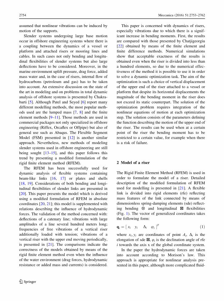
This paper is concerned with dynamics of risers,
especially vibrations due to which there is a signif-
icant increase in bending moments. First, the results
are compared with those presented by Chatjigeorgiu
[22] obtained by means of the finite element and
finite difference methods. Numerical simulations
show that acceptable exactness of the results is
obtained even when the riser is divided into less than
a hundred elements, so due to the numerical effec-
tiveness of the method it is possible to use it in order
to solve a dynamic optimization task. The aim of the
optimization is such a choice of vertical displacement
of the upper end of the riser attached to a vessel or
platform that despite its horizontal displacements the
magnitude of the bending moment in the riser does
not exceed its static counterpart. The solution of the
optimization problem requires integration of the
nonlinear equations of motion at each optimization
step. The solution consists of the parameters defining
the function describing the motion of the upper end of
the riser. The results can be used when at a certain
point of the riser the bending moment has to be
restricted to a certain value, for example when there
is a risk of failure.
2 Model of a riser
The Rigid Finite Element Method (RFEM) is used in
order to formulate the model of a riser. Detailed
description of the modified formulation of RFEM
used for modelling is presented in [21]. A flexible
link is divided into rigid elements (rfe) reflecting
mass features of the link connected by means of
dimensionless spring-damping elements (sde) reflect-
ing bending ⊗ and longitudinal ⊠ flexibilities
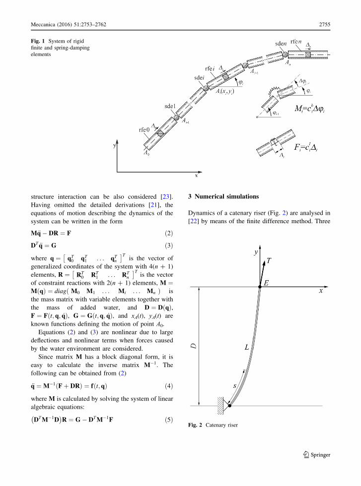
(Fig. 1). The vector of generalized coordinates takes
the following form:
qi ¼ xi yi Di ui½ �T ð1Þwhere xi; yi are coordinates of point Ai, Di is the
elongation of sde ⊠, φi is the declination angle of rfe
i towards the axis x of the global coordinate system.
In the paper the hydrodynamic forces are taken
into account according to Morison’s law. This
approach is appropriate for nonlinear analysis pre-
sented in this paper, although more complicated fluid-
2754 Meccanica (2016) 51:2753–2762
123
structure interaction can be also considered [23].
Having omitted the detailed derivations [21], the
equations of motion describing the dynamics of the
system can be written in the form
M€q� DR ¼ F ð2ÞDT €q ¼ G ð3Þwhere q ¼ qT0 qT1 . . . qTn
� �Tis the vector of
generalized coordinates of the system with 4(n + 1)
elements, R ¼ RT0 RT
1 . . . RTn
� �Tis the vector
of constraint reactions with 2(n + 1) elements, M ¼M qð Þ ¼ diag M0 M1 . . . Mi . . . Mnð Þ is
the mass matrix with variable elements together with
the mass of added water, and D ¼ D qð Þ,F ¼ F t; q; _qð Þ, G ¼ G t; q; _qð Þ, and xA(t), yA(t) are
known functions defining the motion of point A0.
Equations (2) and (3) are nonlinear due to large
deflections and nonlinear terms when forces caused
by the water environment are considered.
Since matrix M has a block diagonal form, it is
easy to calculate the inverse matrix M�1. The
following can be obtained from (2)
€q ¼ M�1 Fþ DRð Þ ¼ f t;qð Þ ð4Þwhere M is calculated by solving the system of linear
algebraic equations:
DTM�1D� �
R ¼ G� DTM�1F ð5Þ
3 Numerical simulations
Dynamics of a catenary riser (Fig. 2) are analysed in
[22] by means of the finite difference method. Three
Fig. 1 System of rigid
finite and spring-damping
elements
Fig. 2 Catenary riser
Meccanica (2016) 51:2753–2762 2755
123
models of risers with different lengths are considered
in order to investigate the influence of heave motion
on bending moments and tension or shear forces.
Axial excitations can have a considerable influ-
ence on dynamic behaviour of risers and catenary
moorings and are especially important in practical
applications. For the purpose of comparative analysis
presented in this section only one of the models is
used. The parameters of the analysed model of the
riser are presented in Table 1.
Two types of harmonic motion are analysed:
W1—vertical motion with period 60 s and ampli-
tude 5 m.
W2—vertical motion with period 12 s and ampli-
tude 2 m.
It is assumed that horizontal motion of a vessel or
platform is described by the following function:
xE ¼ �aþ a cosxt ð6Þwhere a is the amplitude of motion, ω = 2π/T, T is
the period of the harmonic motion.
Comparison of maximal and minimal values of
bending moments as well as tension at the top of the
riser and static top tension are presented in Table 2.
The results obtained with the rigid finite element m
method (RFEM) are compared with those presented
in [22] obtained using RIFLEX (RF) and the finite
difference method (FD).
The results obtained using the rigid finite element
method for n = 101 elements are very close to those
obtained with a nonlinear model (FD). More dis-
crepancies can be seen when the results by the RFEM
are compared with those from the linear model (RF
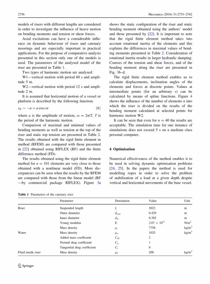
—by commercial package RIFLEX). Figure 3a
shows the static configuration of the riser and static
bending moment obtained using the authors’ model
and those presented by [22]. It is important to note
that the rigid finite element method takes into
account rotational inertia of the elements and this
explains the differences in maximal values of bend-
ing moments presented in Table 2. Consideration of
rotational inertia results in larger hydraulic damping.
Courses of the tension and shear forces, and of the
bending moment along the riser are presented in
Fig. 3b–d.
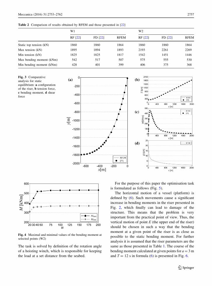
The rigid finite element method enables us to
calculate displacements, inclination angles of the
elements and forces at discrete points. Values at
intermediate points (for an arbitrary s) can be
calculated by means of spline functions. Figure 4
shows the influence of the number of elements n into
which the riser is divided on the results of the
bending moment calculated at selected points for
harmonic motion W2.
It can be seen that even for n = 40 the results are
acceptable. The simulation time for one instance of
simulations does not exceed 5 s on a medium class
personal computer.
4 Optimisation
Numerical effectiveness of the method enables it to
be used in solving dynamic optimisation problems
[24, 25]. In the papers the method is used for
modelling ropes in order to solve the problem
of stabilisation of a load at a given depth despite
vertical and horizontal movements of the base vessel.
Table 1 Parameters of the catenary riser
Parameter Denotation Value Unit
Riser Suspended length L 2022 m
Outer diameter diout 0.429 m
Inner diameter din 0.385 m
Young modulus E 2.07 9 1011 N/m2
Mass density ρr 7758 kg/m3
Water Mass density ρw 1025 kg/m3
Added mass coefficient CM 2
Normal drag coefficient Cn 1
Tangential drag coefficient Ct 0
Fluid inside riser Mass density ρF 200 kg/m3
2756 Meccanica (2016) 51:2753–2762
123
The task is solved by definition of the rotation angle
of a hoisting winch, which is responsible for keeping
the load at a set distance from the seabed.
For the purpose of this paper the optimisation task
is formulated as follows (Fig. 5).
The horizontal motion of a vessel (platform) is
defined by (6). Such movements cause a significant
increase in bending moments in the riser presented in
Fig. 2, which finally can lead to damage of the
structure. This means that the problem is very
important from the practical point of view. Thus, the
vertical motion of point E (the upper end of the riser)
should be chosen in such a way that the bending
moment at a given point of the riser is as close as
possible to the static bending moment. For further
analysis it is assumed that the riser parameters are the
same as those presented in Table 1. The course of the
bendingmoment calculated at given points for a= 3m
and T = 12 s in formula (6) is presented in Fig. 6.
Table 2 Comparison of results obtained by RFEM and those presented in [22]
W1 W2
RF [22] FD [22] RFEM RF [22] FD [22] RFEM
Static top tension (kN) 1860 1860 1864 1860 1860 1864
Max tension (kN) 1895 1894 1893 2193 2261 2269
Min tension (kN) 1825 1825 1817 1542 1451 1446
Max bending moment (kNm) 542 517 507 575 555 530
Min bending moment (kNm) 428 401 399 406 375 368
Fig. 3 Comparative
analysis for static
equilibrium: a configuration
of the riser, b tension force,
c bending moment, d shear
force
Fig. 4 Maximal and minimal values of the bending moment at
selected points (W2)
Meccanica (2016) 51:2753–2762 2757
123
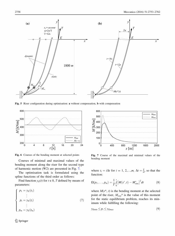
Courses of minimal and maximal values of the
bending moment along the riser for the second type
of harmonic motion (W2) are presented in Fig. 7.
The optimisation task is formulated using the
spline functions of the third order as follows:
Find function yE(t) for t ∊ 0, T defined by means of
parameters:
p1 ¼ yE t1ð Þ...
pi ¼ yE tið Þ...
pm ¼ yE tmð Þ
8>>>>>><>>>>>>:
ð7Þ
where ti ¼ iDt for i = 1, 2,…,m, Dt ¼ Tm, so that the
function:
X p1; . . .; pmð Þ ¼ 1
Trt
0
M s�; tð Þ �M�stat
� �2dt ð8Þ
where M(s*, t) is the bending moment at the selected
point of the riser, Mstat* is the value of this moment
for the static equilibrium problem, reaches its min-
imum while fulfilling the following:
yEmin � pi � yEmax ð9Þ
Fig. 5 Riser configuration during optimisation: a without compensation, b with compensation
Fig. 6 Courses of the bending moment at selected points Fig. 7 Course of the maximal and minimal values of the
bending moment
2758 Meccanica (2016) 51:2753–2762
123
where yEmin; yEmax are minimal and maximal accepted
values of function yE(t).In order to calculate the value
of functional (8) for a specific combination of
parameters pi (i = 1,…,m), bending moment M(s*, t) has to be known. Thus, the equations of motion
of the riser have to be integrated at each optimisation
step. The downhill simplex method is used for
solving the optimisation task.
The parameters occurring in the optimisation
problem have to be chosen properly in order to
obtain correct results, especially the number of time
intervals m in formula (7), and yEmin and yEmax in
inequalities (9). A large number of decisive variables
m significantly increases simulation time, but too
small a number leads to a limitation of function
classes describing vertical displacements of point
E of the riser. Figure 8 presents the courses of
function yE(t) for m = 5, 10, 15.
It can be seen that the difference between values of
yE obtained for m = 5 and 10 is large, while for
m = 10 and 15 it is small. Calculation times were
T* = 202 s for m = 5, T� = 1220 s for m = 10 and
T* = 1825 s for m = 15. The calculations were
carried out for s* = 75 m, yEmin = 1.5 m and
yEmax = 1.5 m. The simulations did not show that
values yEmin and yEmax have a significant influence onthe exactness of results obtained. The choice of yEminand yEmax was made on the assumption that they
should be proportional to the amplitude of the input
motion a, but should not exceed ±50 % of this value.
Fig. 8 Courses of function yE(t) with respect to number of
time intervals m
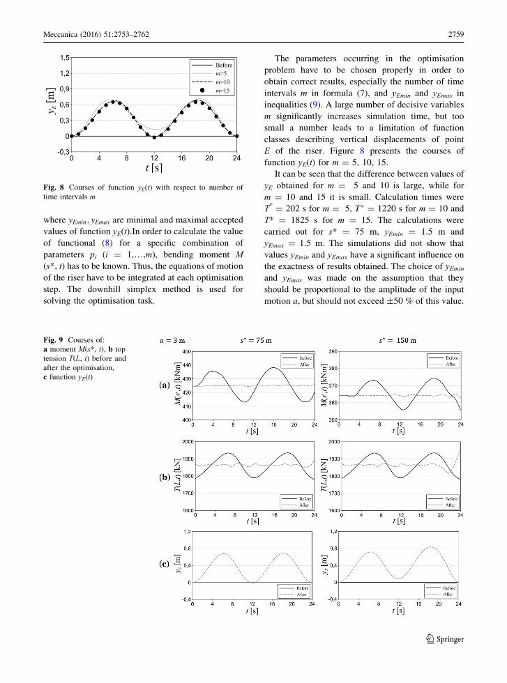
Fig. 9 Courses of:
a moment M(s*, t), b top
tension T(L, t) before and
after the optimisation,
c function yE(t)
Meccanica (2016) 51:2753–2762 2759
123
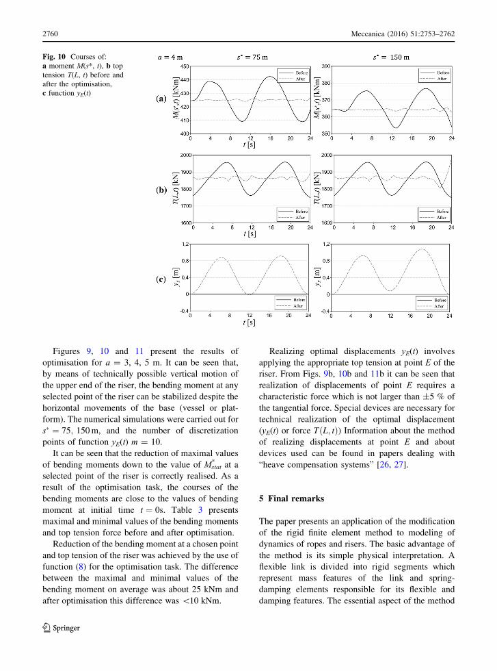
Figures 9, 10 and 11 present the results of
optimisation for a = 3, 4, 5 m. It can be seen that,
by means of technically possible vertical motion of
the upper end of the riser, the bending moment at any
selected point of the riser can be stabilized despite the
horizontal movements of the base (vessel or plat-
form). The numerical simulations were carried out for
s� ¼ 75; 150m, and the number of discretization
points of function yE(t) m = 10.
It can be seen that the reduction of maximal values
of bending moments down to the value of Mstat* at a
selected point of the riser is correctly realised. As a
result of the optimisation task, the courses of the
bending moments are close to the values of bending
moment at initial time t ¼ 0s. Table 3 presents
maximal and minimal values of the bending moments
and top tension force before and after optimisation.
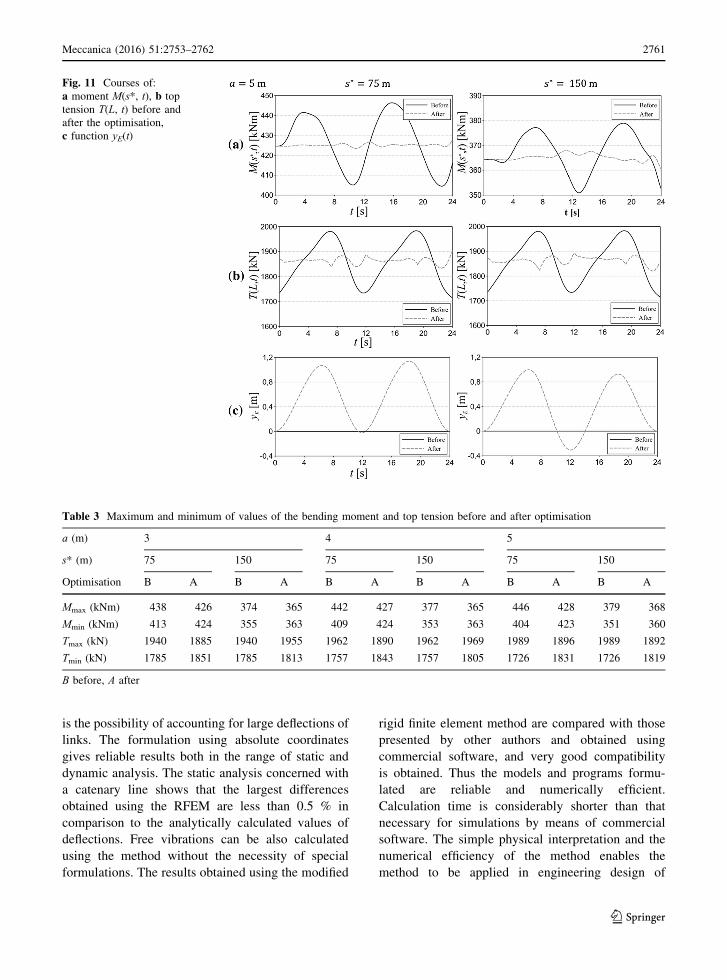
Reduction of the bending moment at a chosen point
and top tension of the riser was achieved by the use of
function (8) for the optimisation task. The difference
between the maximal and minimal values of the
bending moment on average was about 25 kNm and
after optimisation this difference was \10 kNm.
Realizing optimal displacements yE(t) involves
applying the appropriate top tension at point E of the
riser. From Figs. 9b, 10b and 11b it can be seen that
realization of displacements of point E requires a
characteristic force which is not larger than ±5 % of
the tangential force. Special devices are necessary for
technical realization of the optimal displacement
(yE(t) or force T L; tð Þ) Information about the method
of realizing displacements at point E and about
devices used can be found in papers dealing with
“heave compensation systems” [26, 27].
5 Final remarks
The paper presents an application of the modification
of the rigid finite element method to modeling of
dynamics of ropes and risers. The basic advantage of
the method is its simple physical interpretation. A
flexible link is divided into rigid segments which
represent mass features of the link and spring-
damping elements responsible for its flexible and
damping features. The essential aspect of the method
Fig. 10 Courses of:
a moment M(s*, t), b top
tension T(L, t) before and
after the optimisation,
c function yE(t)
2760 Meccanica (2016) 51:2753–2762
123
is the possibility of accounting for large deflections of
links. The formulation using absolute coordinates
gives reliable results both in the range of static and
dynamic analysis. The static analysis concerned with
a catenary line shows that the largest differences
obtained using the RFEM are less than 0.5 % in
comparison to the analytically calculated values of
deflections. Free vibrations can be also calculated
using the method without the necessity of special
formulations. The results obtained using the modified
rigid finite element method are compared with those
presented by other authors and obtained using
commercial software, and very good compatibility
is obtained. Thus the models and programs formu-
lated are reliable and numerically efficient.
Calculation time is considerably shorter than that
necessary for simulations by means of commercial
software. The simple physical interpretation and the
numerical efficiency of the method enables the
method to be applied in engineering design of
Table 3 Maximum and minimum of values of the bending moment and top tension before and after optimisation
a (m) 3 4 5
s* (m) 75 150 75 150 75 150
Optimisation B A B A B A B A B A B A
Mmax (kNm) 438 426 374 365 442 427 377 365 446 428 379 368
Mmin (kNm) 413 424 355 363 409 424 353 363 404 423 351 360
Tmax (kN) 1940 1885 1940 1955 1962 1890 1962 1969 1989 1896 1989 1892
Tmin (kN) 1785 1851 1785 1813 1757 1843 1757 1805 1726 1831 1726 1819
B before, A after
Fig. 11 Courses of:
a moment M(s*, t), b top
tension T(L, t) before and
after the optimisation,
c function yE(t)
Meccanica (2016) 51:2753–2762 2761
123
offshore equipment, especially in dynamic analysis of
flexible structures, dynamic optimization problems
and control. An exemplary optimisation problem is
presented and solved in the paper. However, the
problem can be generalized by including several
points along the riser in the functional Ω. Since the
method enables us to calculate forces in the connec-
tions of the elements (as constraint reactions) it is
possible to formulate tasks in which the limitations
are imposed not only on the bending moment but also
longitudinal or transversal forces. Solution of several
optimisation tasks (for example for different param-
eters of waves, length of risers) can be used for
training an artificial neural network, which then can
be used in control.
Open Access This article is distributed under the terms of the
Creative Commons Attribution 4.0 International License
(http://creativecommons.org/licenses/by/4.0/), which permits
unrestricted use, distribution, and reproduction in any
medium, provided you give appropriate credit to the original
author(s) and the source, provide a link to the Creative
Commons license, and indicate if changes were made.
References
1. Benedettini F, Rega G, Vestroni F (1986) Modal coupling
in the free nonplanar finite motion of an elastic cable.
Meccanica 21:38–46
2. Benedettini F, Rega G, Alaggio R (1995) Non-linear
oscillations of a four-degree-of-freedom model of a sus-
pended cable under multiple internal resonance conditions.
J Sound Vib 182(5):775–798
3. Rega G, Alaggio R, Benedettini F (1997) Experimental
investigation of the nonlinear response of a hanging cable.
Part I: local analysis. Nonlinear Dyn 14:89–117
4. Benedettini F, Rega G (1997) Experimental investigation
of the nonlinear response of a hanging cable. Part I: global
analysis. Nonlinear Dyn 14:119–138
5. Chakrabarti S (2008) Challenges for a total system analysis
on deepwater floating systems. Open Mech J 2:28–46
6. Patel MH, Seyed FB (1995) Review of flexible riser
modelling analysis techniques. Eng Struct 17(4):293–304
7. Raman-Nair W, Baddour R (2003) Three-dimensional
dynamics of a flexible marine riser undergoing large elastic
deformations. Multibody Syst Dyn 10:393–423
8. Liping S, Bo Q (2011) Global analysis of a flexible riser.
J Mar Sci Appl 10:478–484
9. Kaewunruen S, Chiravatchradej J, Chucheepsakul S (2005)
Nonlinear free vibrations of marine risers/pipes transport-
ing fluid. Ocean Eng 32:417–440
10. Park H-I, Jung D-H (2002) A finite element method for
dynamic analysis of long slender marine structures under
combined parametric and forcing excitations. Ocean Eng
29:1313–1325
11. Chai YT, Varyani KS (2006) An absolute coordinate for-
mulation for three-dimensional flexible pipe analysis.
Ocean Eng 33:23–58
12. Xu X, Wang S (2012) A flexible-segment-model-based
dynamics calculation method for free hanging marine ris-
ers in re-entry. China Ocean Eng 26:139–152
13. Jensen GA, Safstrom N, Nguyen TD, Fossen TF (2000) A
nonlinear PDE formulation for offshore vessel pipeline
installation. Ocean Eng 37:365–377
14. Niedzwecki JM, Liegre P-YF (2003) System identification
of distributed-parameter marine riser models. Ocean Eng
33:1387–1415
15. Chen H, Xu S, Guo H (2011) Nonlinear analysis of flexible
and steel catenary risers with internal flow and seabed
interaction effects. J Mar Sci Appl 10:156–162
16. Wittbrodt E, Adamiec-Wojcik I, Wojciech S (2006)
Dynamics of flexible multibody systems: rigid finite ele-
ment method. Springer, Berlin
17. Wittbrodt E, Szczotka M, Maczynski A, Wojciech S
(2012) Rigid finite element method in analysis of dynamics
of offshore structures. Springer, Berlin
18. Adamiec-Wojcik I, Nowak A, Wojciech S (2011) Com-
parison of methods for vibration analysis of electrostatic
precipitators. Acta Mech Sin 27:72–79
19. Adamiec-Wojcik I, Awrejcewicz J, Nowak A, Wojciech S
(2014) Vibration analysis of collecting electrodes by
means of the hybrid finite element method. Math Probl
Eng. doi:10.1155/2014/832918
20. Adamiec-Wojcik I, Awrejcewicz J, Brzozowska L, Drag Ł
(2014) Modeling of ropes with consideration of large
deformations by means of the rigid finite element method.
Appl Non-linear Dyn Syst Springer Proc Math Stat
93:115–137
21. Adamiec-Wojcik I, Brzozowska L, Drag Ł (2015) An
analysis of dynamics of risers during vessel motion by
means of the rigid finite element method. Ocean Eng
106:102–114
22. Chatjigeorgiou IK (2008) A finite difference formulation
for the linear and nonlinear dynamics of 2D catenary risers.
Ocean Eng 35:616–636
23. Sorokin SV, Rega G (2007) On modelling and linear
vibrations of arbitrarily sagged inclined cables in a quies-
cent viscous fluid. J Fluid Struct 23:1077–1092
24. Drag Ł (2016) Model of an artificial neural network for
optimization of payload positioning in sea waves. Ocean
Eng 115:123–134
25. Drag Ł (2016) Application of dynamic optimisation to the
trajectory of a cable suspended load. Nonlinear Dyn. doi:
10.1007/s11071-015-2593-0
26. Rustad AM, Larsen CM, Sorensen AJ (2008) FEM mod-
elling and automatic control for collision prevention of top
tensioned raisers. Mar Struct 21:80–112
27. Do KD, Pan J (2008) Nonlinear control of an active heave
compensation system. Ocean Eng 35:558–571
2762 Meccanica (2016) 51:2753–2762
123