Embed Size (px)
Citation preview

Complete Barrel Measuring and Inspection System
PS Series
User’s manual

SAFETY PRECAUTIONS .............................................................................................................................................. 3
ELECTROMAGNETIC COMPATIBILITY ................................................................................................................. 3
LASER SAFETY .............................................................................................................................................................. 3
GENERAL INFORMATION ......................................................................................................................................... 3
BASIC DATA AND PERFORMANCE CHARACTERISTICS .................................................................................. 4
COMPLETE SET TO BE SUPPLIED .......................................................................................................................... 4
STRUCTURE AND OPERATING PRINCIPLE ......................................................................................................... 5 STRUCTURE ...................................................................................................................................................................................... 5 OPERATION PRINCIPLE .................................................................................................................................................................. 5 SELF-MOVING WIRELESS PROBE ................................................................................................................................................... 6 USING OF PIPE EXTENDER ............................................................................................................................................................. 7 BASIC TECHNICAL DATA................................................................................................................................................................. 7
EXAMPLE OF ITEM DESIGNATION WHEN ORDERING .................................................................................... 7
DIMENSIONS ................................................................................................................................................................. 8 OVERALL DIMENSIONS ................................................................................................................................................................... 8
CONNECTION .............................................................................................................................................................. 10
MEASUREMENT PROCEDURE ............................................................................................................................... 10 PREPARATION FOR USE ............................................................................................................................................................... 10 MEASUREMENT ............................................................................................................................................................................ 10 SOFTWARE .................................................................................................................................................................................... 11 MEASUREMENT RESULT ............................................................................................................................................................. 14
MEASURING CHANNELS .......................................................................................................................................... 14 VIDEO INSPECTION CHANNEL .................................................................................................................................................... 14 ROTATING LASER TRIANGULATION SCANNER ......................................................................................................................... 15 NON-STRAIGHTNESS (WARPAGE) PSD SENSOR ..................................................................................................................... 15 TEMPERATURE SENSOR .............................................................................................................................................................. 15 INCLINOMETER ............................................................................................................................................................................. 16 LASER DISTANCE SENSOR ........................................................................................................................................................... 16
CALIBRATION ............................................................................................................................................................. 16
WARRANTY POLICY ................................................................................................................................................. 17

Safety precautions � Read this manual carefully prior to using the system.
� Use supply voltage and interfaces indicated in the system specifications.
� In connection/disconnection of cables, the system power must be switched off.
� To obtain stable results, crucial 10 minutes warm-up should be performed.
Electromagnetic compatibility The system is developed for industrial use and meet the requirements of the following standards:
� EN 55022:2006 Information Technology Equipment. Radio disturbance characteristics. Limits and methods of measurement.
� EN 61000-6-2:2005 Electromagnetic compatibility (EMC). Generic standards. Immunity for industrial environments.
� EN 61326-1:2006 Electrical Equipment for Measurement, Control, and Laboratory Use. EMC Requirements. General requirements.
Laser safety The system corresponds to the 2M safety classes according to IEC 60825-1:2007 The system makes use of an c.w. 660 nm or 405 wavelength semiconductor laser. The system belongs to the 2M laser safety class. The following warning label is placed on system's parts:
The following safety measures should be taken while operating the system:
� Do not target laser beam to humans;
� Do not disassemble any parts of the system;
� Avoid staring into the laser beam;
General information The system is intended for the video inspection and the laser non-contact measuring and scanning of internal surface of pipes, tubes and barrels. The system allows to measure following parameters:
� inner diameter; � ovality; � out-of-roundness; � non-straightness (warpage); � distance from the edge of the pipe; � rifling height;

rifling width; rifling angle;
Basic data and performance characteristics Name of parameter Value, mm Resolution, mm Linearity, mm Inner diameter Ovality Out-of-roundness
57-120 - -
0,005 0,005 0,005
0,01 0,01 0,01
Non-straightness (warpage)
±4 (X) ±4 (Y)
0,001 0,001
0,005 0,005
Rifling height Rifling width
0.5 -4.5 2 - 7
0,05 0,05
0,1 0,1
Rifling angle (deg) - 0,004 ̊ 0,008 ̊
Complete set to be supplied Designation Name Quantity Weight, kg PS-SP Self-moving wireless probe 1 PS-LS Adjustable laser source 1 PS-TL Target for laser beam adjustment 1 PS-CC Connection cables 1 PS-LN Wireless data router 1 PS-CB Calibration block 1 PS-S Software 1 PS-UM User manual 1 Options: PS-EX (d) Pipe extender

Structure and operating principle
Structure
Figure: The PS-120/154 (long version) system without transport box
Operation principle In order to prepare for the measurement, the laser source is to be placed at one end of the tube. The target for laser beam adjustment is to be placed at opposite end of the tube. The user should aim the laser beam in the centre of the target using special adjustment screws and then remove the target.
Figure. The adjustable laser source (PS-125)
Figure. The target for laser beam adjustment (PS-125)

Then the probe is to be inserted into the tube. All the rest processes are handled automatically after pushing «Start» button. Status of measuring is displayed on the laptop/PC screen. The final report can be printed or stored in a database or in a memory card. The laser source is connected to AC/DC power unit or battery by the cable. The probe is connected by wireless Wi-fi connection and has an internal battery. The probe motion control and data transaction are wireless. The probe moves along the tube automatically following a measurement template. The probe carries out measurements over the entire barrel surface excluding the areas (at the beginning and at the end) which do not exceed 60 mm. One may use a special extender (option) allowing measurement of the whole surface. The system uses special spring-loaded extending rollers to adjust the probe in the tube. Replacement of centring rollers and drive unit permits controlling wide range of tubes with inner diameters from 57mm to 120mm. The module which is located on the front of the probe can be easily replaced and provides either video inspection (Video Channel) or non-straightness (warpage) measuring (Non-straightness Channel); The Video Channel houses a 5 Mpix camera with fish-eye lens and 3 channel LED lighting system especially designed for hi-res video inspection of tube interiors. The laser distance gauge measures the distance from the probe to the tube muzzle end to bind measured results to the probe position.
Self-moving wireless probe The self-moving wireless probe contains following modules and sensors:
rotating laser triangulation scanner; non-straightness (warpage) PSD sensor; temperature sensor; 3-channel LED lightning system; video inspection camera; inclinometer; laser distance sensor; accelerometer; moving module; centering module; electronic module;
Using of pipe extender The probe carries out measurements over the entire barrel surface excluding the areas (at the beginning and at the end) which do not exceed 60 mm. One may use a special extender (option) allowing measurement of the whole surface. The universal (adjustable) pipe extender (for wide range of the pipe) is available to order as well.
Figure. The extender for PS-125 (Diameter 125 mm)
Basic technical data Name of parameter Value Operating temperature - 20…+ 65о С Storage temperature - 50…+ 65о С Humidity up to 98% Power supply Rechargeable battery SAFT 34570
220 V AC, 50 Hz (or 24V DC) Battery lifetime Up to 8 hours Power 5 W Interface to PC Wi-Fi IEEE 802.11n Antenna 2.4 GHz, 6 dB Moving speed 11 m per minute
Example of item designation when ordering Following modifications are available to order:
PS- 57/120 125 120/159 Type of barrels Smooth/rifled Smooth Smooth/rifled Range of inner diameter
From 57 to 120 mm From 120 to 130 mm
From 120 to 159 mm
Type of laser sensor (inner diameter)
Rotating laser triangulation
scanner
6-beam laser triangulation sensor
Rotating laser triangulation
scanner Non-straightness (warpage) PSD sensor
Option (-NS)
+ Option (-NS)
Temperature sensor
+ + +
3-channel LED lightning system
+ - +

Video inspection camera
+ - +
Laser distance sensor
+ + +
Inclinometer + + + Accelerometer + + + Moving module Option -SM + Option -SM Pipe extender Option -PE (d) Option -PE (d) Option -PE (d) Long version - - Option –L Special version for the vertically arranged pipe with a winch
Available Type PSV-
Ask for more info
- Available Type PSV-
Ask for more info
Example: PIOS-57/120-NS-SM-PE (57, 98, 120) — the self moving system for inner diameter from 57 to 120 mm with PSD warpage sensor and pipe extruders for inner diameters 55, 98 and 120 mm.
Dimensions
Overall dimensions Overall dimensions of all parts of the system are shown on Figure below. All parts of the system are made of anodized aluminium. Detailed CAD documentation is available here link.
Figure. PS-57/120 adjustable laser source
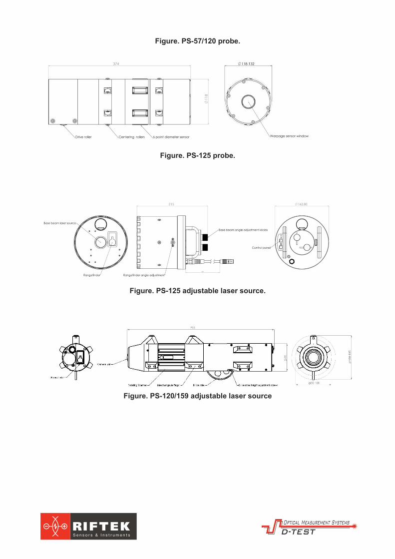
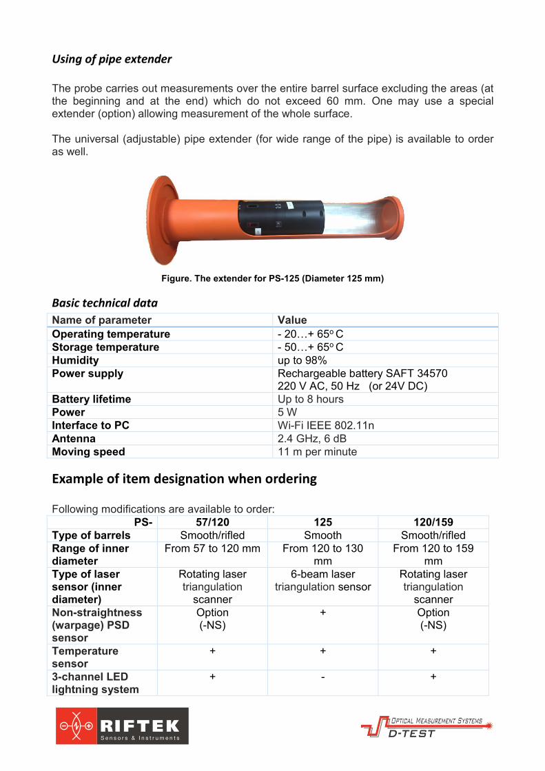
Figure. PS-57/120 probe.
Figure. PS-125 probe.
Figure. PS-125 adjustable laser source.
Figure. PS-120/159 adjustable laser source

Connection
The connection diagram is showed below:
All systems in the PS series have a similar wire connection.
Measurement procedure
Preparation for use Before using the system should be got out of the transport box. If the system has been stored in extremely hot or cold conditions all parts of the instrument must be kept in normal environment for at least 10 minutes prior to using.
Measurement The operator connects all cables as it showed in Connection chapter. The laser source is to be placed at one end of the tube. The target for laser beam adjustment is to be placed at opposite end of the tube. The operator should aim the laser beam in the centre of the target using special adjustment screws and then remove the target.
The probe is to be inserted to the tube. The system includes special software, which allows operating and calibrating the device. The software can be installed on any Windows-based PC/laptop. The computer must have Wi-Fi wireless adapter or integrated wireless chip. In order to measure, the operator launches ps_software.exe file and then fills out (or select from macros’s library) following fields:
identifier of the pipe (pipe's number); list of sections to control (by OZ axis); limits values for all parameters;
All the rest processes are handled automatically after pushing «Connect» and «Auto

measure» buttons. Status of measuring is displayed on the laptop/PC screen. The final report can be printed or stored in a database or on a memory card. The operator is able to use “Manual mode” to control particular sections as well.
Software
Figure. The main form
Figure. The example of a profile (the caliber)
AREA FIELDS/BUTTONS FUNCTION
SECTION PROFILE The area for showing the profile of a section PROFILE MEASUREMENT The area for showing the parameters of a section
Fields: Inner diameter The inner diameter in current section Rifling diameter The rifling diameter in current section Inner ovality The inner ovality in current section Rifling ovality The rifling ovality in current section Gap width The gap width in current section Rifling width The rifling width in current section
Buttons: Start measure To measure in current section (manual mode) Stop measure To stop measuring Save result Profiles saving into the file

Protocol To open the protocol form Calibrate To open the calibration form
VIDEO INSPECTION Lightning
Buttons: Load preset To load preset from the internal controller Save to preset To save preset to the internal controller Channel 1/2/3 Fine and Rough tunes for lighting (separately for
each from three channels) Video inspection Connect video To connect a video camera. Screenshot To save a current shot to a database Capture To start video capturing Full screen Switch to full screen mode Exposure ROI To change exposure PARAMETERS
Buttons: Connect To connect with the probe Main on To switch all the sensors on Exit To exit from the program
PROBE CONNECTION Fields: Bore # Number of the barrel
Bore type Type of the barrel Buttons: Bore type edit To open “Bore type” library
Section step edit To open “Section step” form PROBE POSITIONING
Fields: Next section Indication of next section position Probe position Indication of current probe position Probe angle Indication of current section angle
Buttons: Next section To choose the next section in a manual mode Previous section To choose the previous section in a manual mode Set Zero To set logical O for OZ axis
Figure. “Bore type” library

Figure. The “Section step” form
AREA FIELDS/BUTTONS FUNCTION
SECTION STEP The form for determination of macros in automatic mode
Fields: First section The first section to measure, mm Last section The last section to measure, mm Step The step between sections, mm
Buttons: Update To update the macros
Figure. The protocol form
AREA FIELDS/BUTTONS FUNCTION
PROTOCOL ARCHIVE The list of all saved protocols MEASURED VALUES A chart showing an inner diameter for all the
length of the barrel SECTION PROFILE A chart showing a barrel profile in the
selected section (User can switch a circle chart as well)
The table below Showing all parameters of the barrel in selected section
BUTTONS BELOW

Delete protocol To delete the selected protocol Print protocol To print the selected protocol out
Close To close the form Screenshot To show/print out a screenshot for the
selected section Video stream To play a video stream Gradient diagram To show/print out a gradient diagram for the
selected protocol
Figure. The protocol form (Zoom mode)
Measurement result The measurement result also can be displayed as:
2D cross section; linear un-warped display; gradient diagram; tables; graphs.
The measurement result is stored in the database and can be opened and printed in any time. The form of the protocol (a visualization of the result) might be changed according to customer requirements.
Measuring channels
Video inspection channel Video inspection channel is switched on immediately after plugging in the probe. The user can manage lighting via special form in software “Brightness”. Using this form the operator can reach quality lighting on all parts of the pipe. It is possible to adjust three channel of light module separately in order to eliminate reflections, highlights etc. The picture from the camera can be present as a small video area inside the main form and as full-screen picture. Switching between these modes is by pushing “Fullscreen” button. The button “Save image” allows saving JPEG on hard disk. The button “Save movie” activates a video capture mode. The filename is formed of the number of the pipe, the current date and the current probe position in the tube. The system uses ultra-wide lenses (similar with a fish-eye lens) and HDR camera. Special algorithm eliminates circular distortions and converts o-shaped “fish-eye” picture into usual flat image. See the Figure below.

Figure. Comparing picture after algorithm (left picture) and before.
Rotating laser triangulation scanner The rotating laser triangulation scanner consists of two or four laser triangulation sensors. Operation of the sensors is based on the principle of optical triangulation. The radiation of a semiconductor laser is focused by a lens onto an object. The radiation reflected by the object is collected by a lens onto a linear CCD-array. A signal processor calculates the distance to the object from the position of the light spot on the array. Each sensor of the scanner covers its own range of diameter. All sensors summary cover all the range of pipes.
Non-straightness (warpage) PSD sensor The non-straightness (warpage) channel consists of a PSD matrix and stabilized laser source. The laser source is placed at one end of the tube. The laser beam emits through the pipe. The radiation of a semiconductor laser is focused onto PSD matrix located inside the self-moving probe. A position of the laser point on the matrix is determined permanently and allows calculating an offset between the probe and the laser beam. Since the probe is centered in the pipe and follows the profile of the pipe during measuring, the system can measure the non-straightness (warpage) using the position of laser point on the PSD matrix.
Figure. The Principle of non-straightness measurement.
Temperature sensor The temperature sensor is designed to compensate for the distortion of the system readings relating to changes in ambient temperature. This makes it possible to achieve high accuracy over a wide temperature range.
Inclinometer The inclinometer is intended to compensate for the distortion of the system readings relating to possible spin or tilt of the probe.
Laser distance sensor The laser distance sensor is located on the rear unit of the probe and intended to determine a position of the probe inside the pipe (distance between the edge of the pipe and the probe). The laser distance sensor allow measuring a distance in the range from 50 to 20000 mm with linearity +/-1 mm. Measurement frequency is 2 Hz.
Calibration The first calibration is done by the manufacture. All parts of the system contain special features for self-diagnostic. However, the operator should do a periodic calibration once a year or more often if it is required. The system includes special calibration block, which allows checking instrument's accuracy anytime and fixing calibration table if it is necessary. The calibration takes 10-15 minutes. All calibration processes are automatic.
Figure. The caliber for PS-57/120 and PS-120/159
The calibration block contains a caliber (see pictures), which is used to correlate the readings of the system with factory values in order to check the system's accuracy. The inner surface of the caliber emulates a plenty of pipes with different diameters in all working range. In order to calibrate, the probe should be inserted into the calibration block as it is showed on the picture below. The calibration starts automatically after pushing “Calibration” button.

Figure. The PS-57/120 probe inside the caliber
In order to calibrate non-straightness (warpage) channel, the operator mounts 2-axis motorized positioner to the calibration block. The laser source is located in the centre of the positioner. Using special module in Software the system provides an automatic calibration in all the range. A calibration table is uploaded to system’s controller.
Warranty policy The factory guarantees a normal system condition within 2 years from the date of manufacturing.