Embed Size (px)
Citation preview

Complete Hardware Guide for EX2200 EthernetSwitches
Modified: 2015-06-23
Revision 16
Copyright © 2015, Juniper Networks, Inc.

Juniper Networks, Inc.1133 InnovationWaySunnyvale, California 94089USA408-745-2000www.juniper.net
Juniper Networks, Junos, Steel-Belted Radius, NetScreen, and ScreenOS are registered trademarks of Juniper Networks, Inc. in the UnitedStates and other countries. The Juniper Networks Logo, the Junos logo, and JunosE are trademarks of Juniper Networks, Inc. All othertrademarks, service marks, registered trademarks, or registered service marks are the property of their respective owners.
Juniper Networks assumes no responsibility for any inaccuracies in this document. Juniper Networks reserves the right to change, modify,transfer, or otherwise revise this publication without notice.
Complete Hardware Guide for EX2200 Ethernet SwitchesCopyright © 2015, Juniper Networks, Inc.All rights reserved.
Revision HistoryJuly 2014—Revision 16June 2014—Revision 15April 2014—Revision 14March 2014—Revision 13January 2013—Revision 12September 2012—Revision 11September 2012—Revision 10March 2012—Revision 9November 2011—Revision 8September 2011—Revision 7July 2011—Revision 6March 2011—Revision 5December 2010—Revision 4August 2010—Revision 3May 2010—Revision 2February 2010—Revision 1
The information in this document is current as of the date on the title page.
YEAR 2000 NOTICE
Juniper Networks hardware and software products are Year 2000 compliant. Junos OS has no known time-related limitations through theyear 2038. However, the NTP application is known to have some difficulty in the year 2036.
SOFTWARE LICENSE
The terms and conditions for using this software are described in the software license contained in the acknowledgment to your purchaseorder or, to the extent applicable, to any reseller agreement or end-user purchase agreement executed between you and Juniper Networks.By using this software, you indicate that you understand and agree to be bound by those terms and conditions.
Generally speaking, the software license restricts the manner in which you are permitted to use the software andmay contain prohibitionsagainst certain uses. The software license may state conditions under which the license is automatically terminated. You should consultthe license for further details.
For complete product documentation, please see the Juniper NetworksWeb site at www.juniper.net/techpubs.
ENDUSER LICENSE AGREEMENT
The Juniper Networks product that is the subject of this technical documentation consists of (or is intended for use with) Juniper Networkssoftware. Use of such software is subject to the terms and conditions of the End User License Agreement (“EULA”) posted athttp://www.juniper.net/support/eula.html. By downloading, installing or using such software, you agree to the terms and conditions ofthat EULA.
Copyright © 2015, Juniper Networks, Inc.ii
Table of Contents
About the Documentation . . . . . . . . . . . . . . . . . . . . . . . . . . . . . . . . . . . . . . . . . xiii
Junos OS Documentation and Release Notes . . . . . . . . . . . . . . . . . . . . . . . . . xiii
Documentation Conventions . . . . . . . . . . . . . . . . . . . . . . . . . . . . . . . . . . . . . . xiii
Documentation Feedback . . . . . . . . . . . . . . . . . . . . . . . . . . . . . . . . . . . . . . . . . xv
Requesting Technical Support . . . . . . . . . . . . . . . . . . . . . . . . . . . . . . . . . . . . . xv
Self-Help Online Tools and Resources . . . . . . . . . . . . . . . . . . . . . . . . . . . xvi
Opening a Case with JTAC . . . . . . . . . . . . . . . . . . . . . . . . . . . . . . . . . . . . . xvi
Part 1 Switch and Components Overview and Specifications
Chapter 1 EX2200 Switch Overview . . . . . . . . . . . . . . . . . . . . . . . . . . . . . . . . . . . . . . . . . . . 3
EX2200 Switches Hardware Overview . . . . . . . . . . . . . . . . . . . . . . . . . . . . . . . . . . . 3
EX2200 Switches First View . . . . . . . . . . . . . . . . . . . . . . . . . . . . . . . . . . . . . . . . 3
Uplink Ports . . . . . . . . . . . . . . . . . . . . . . . . . . . . . . . . . . . . . . . . . . . . . . . . . . . . . 4
Console Port . . . . . . . . . . . . . . . . . . . . . . . . . . . . . . . . . . . . . . . . . . . . . . . . . . . . 4
Cable Guard . . . . . . . . . . . . . . . . . . . . . . . . . . . . . . . . . . . . . . . . . . . . . . . . . . . . 5
Security Slots . . . . . . . . . . . . . . . . . . . . . . . . . . . . . . . . . . . . . . . . . . . . . . . . . . . 5
Power over Ethernet (PoE) Ports . . . . . . . . . . . . . . . . . . . . . . . . . . . . . . . . . . . . 5
Front Panel of an EX2200 Switch . . . . . . . . . . . . . . . . . . . . . . . . . . . . . . . . . . . 6
Rear Panel of an EX2200 Switch . . . . . . . . . . . . . . . . . . . . . . . . . . . . . . . . . . . . 7
EX2200 Switch Models . . . . . . . . . . . . . . . . . . . . . . . . . . . . . . . . . . . . . . . . . . . . . . . 9
Chassis Physical Specifications for EX2200 Switches . . . . . . . . . . . . . . . . . . . . . . . 9
EX2200 Switch Hardware and CLI Terminology Mapping . . . . . . . . . . . . . . . . . . . 10
Chapter 2 Component Descriptions . . . . . . . . . . . . . . . . . . . . . . . . . . . . . . . . . . . . . . . . . . . 13
Chassis Status LEDs in EX2200 Switches . . . . . . . . . . . . . . . . . . . . . . . . . . . . . . . . 13
Network Port and Uplink Port LEDs in EX2200 Switches . . . . . . . . . . . . . . . . . . . . 14
Management Port LEDs in EX2200 Switches . . . . . . . . . . . . . . . . . . . . . . . . . . . . . 17
Power Supply in EX2200 Switches . . . . . . . . . . . . . . . . . . . . . . . . . . . . . . . . . . . . . 18
Cooling System and Airflow in an EX2200 Switch . . . . . . . . . . . . . . . . . . . . . . . . . 19
Airflow Direction in Non-PoE Models of EX2200 Switches, Except for the
EX2200-C Models . . . . . . . . . . . . . . . . . . . . . . . . . . . . . . . . . . . . . . . . . . . 19
Airflow Direction in PoE Models of EX2200 switches, Except for the
EX2200-C Models . . . . . . . . . . . . . . . . . . . . . . . . . . . . . . . . . . . . . . . . . . . 20
Chapter 3 Component Specifications . . . . . . . . . . . . . . . . . . . . . . . . . . . . . . . . . . . . . . . . . 21
USB Port Specifications for an EX Series Switch . . . . . . . . . . . . . . . . . . . . . . . . . . . 21
Mini-USB Port Specifications for an EX2200 Switch . . . . . . . . . . . . . . . . . . . . . . . 22
Network Port Connector Pinout Information for an EX2200 Switch . . . . . . . . . . . 23
Console Port Connector Pinout Information for an EX Series Switch . . . . . . . . . . 23
RJ-45 to DB-9 Serial Port Adapter Pinout Information for a Switch . . . . . . . . . . . 25
iiiCopyright © 2015, Juniper Networks, Inc.
Management Port Connector Pinout Information for an EX2200 Switch . . . . . . . 25
Pluggable Transceivers Supported on EX2200 Switches . . . . . . . . . . . . . . . . . . . 26
Part 2 Planning for Switch Installation
Chapter 4 Site Preparation . . . . . . . . . . . . . . . . . . . . . . . . . . . . . . . . . . . . . . . . . . . . . . . . . . . 61
Site Preparation Checklist for EX2200 Switches . . . . . . . . . . . . . . . . . . . . . . . . . . 61
General Site Guidelines . . . . . . . . . . . . . . . . . . . . . . . . . . . . . . . . . . . . . . . . . . . . . . 62
Site Electrical Wiring Guidelines . . . . . . . . . . . . . . . . . . . . . . . . . . . . . . . . . . . . . . . 63
Environmental Requirements and Specifications for EX Series Switches . . . . . . . 65
Chapter 5 Mounting and Clearance Requirements . . . . . . . . . . . . . . . . . . . . . . . . . . . . . . . 71
Rack Requirements for EX2200 Switches . . . . . . . . . . . . . . . . . . . . . . . . . . . . . . . . 71
Cabinet Requirements for EX2200 Switches . . . . . . . . . . . . . . . . . . . . . . . . . . . . . 72
Requirements for Mounting an EX2200 Switch on a Desktop or Wall . . . . . . . . . . 73
Clearance Requirements for Airflow and Hardware Maintenance for EX2200
Switches . . . . . . . . . . . . . . . . . . . . . . . . . . . . . . . . . . . . . . . . . . . . . . . . . . . . . . 74
Chapter 6 Cable Specifications . . . . . . . . . . . . . . . . . . . . . . . . . . . . . . . . . . . . . . . . . . . . . . . 77
Network Cable Specifications for EX2200 Switches . . . . . . . . . . . . . . . . . . . . . . . 77
Chapter 7 Planning Power Requirements . . . . . . . . . . . . . . . . . . . . . . . . . . . . . . . . . . . . . . 79
Power Specifications for EX2200 Switches . . . . . . . . . . . . . . . . . . . . . . . . . . . . . . 79
AC Power Cord Specifications for EX2200 Switches . . . . . . . . . . . . . . . . . . . . . . . 80
Part 3 Installing and Connecting the Switch and Switch Components
Chapter 8 Installing the Switch . . . . . . . . . . . . . . . . . . . . . . . . . . . . . . . . . . . . . . . . . . . . . . 85
Installing and Connecting an EX2200 Switch . . . . . . . . . . . . . . . . . . . . . . . . . . . . 85
Unpacking an EX2200 Switch . . . . . . . . . . . . . . . . . . . . . . . . . . . . . . . . . . . . . . . . . 86
Parts Inventory (Packing List) for an EX2200 Switch . . . . . . . . . . . . . . . . . . . . . . . 87
Mounting an EX2200 Switch . . . . . . . . . . . . . . . . . . . . . . . . . . . . . . . . . . . . . . . . . 88
Mounting an EX2200 Switch on a Desk or Other Level Surface . . . . . . . . . . . . . . 89
Mounting an EX2200 Switch On or Under a Desk Using Screws . . . . . . . . . . . . . . 92
Mounting an EX2200 Switch on Two Posts of a Rack or Cabinet . . . . . . . . . . . . . 95
Mounting an EX2200 Switch on Four Posts of a Rack or Cabinet . . . . . . . . . . . . . 98
Mounting an EX2200 Switch in a Recessed Position in a Rack or Cabinet . . . . . 102
Mounting an EX2200 Switch on a Wall . . . . . . . . . . . . . . . . . . . . . . . . . . . . . . . . . 102
Mounting an EX2200 Switch Except the EX2200-C Model on a Wall . . . . . 102
Mounting an EX2200-C Switch on a Wall . . . . . . . . . . . . . . . . . . . . . . . . . . . 105
Mounting an EX2200 Switch Using the Magnet Mount . . . . . . . . . . . . . . . . . . . . 109
Chapter 9 Installing Switch Components . . . . . . . . . . . . . . . . . . . . . . . . . . . . . . . . . . . . . . 113
Installing a Transceiver in an EX Series Switch . . . . . . . . . . . . . . . . . . . . . . . . . . . . 113
Chapter 10 Connecting the Switch . . . . . . . . . . . . . . . . . . . . . . . . . . . . . . . . . . . . . . . . . . . . . 117
Connecting Earth Ground to an EX Series Switch . . . . . . . . . . . . . . . . . . . . . . . . . . 117
Parts and Tools Required for Connecting an EX Series Switch to Earth
Ground . . . . . . . . . . . . . . . . . . . . . . . . . . . . . . . . . . . . . . . . . . . . . . . . . . . . 118
Special Instructions to Follow Before Connecting Earth Ground to a
Switch . . . . . . . . . . . . . . . . . . . . . . . . . . . . . . . . . . . . . . . . . . . . . . . . . . . . 120
Copyright © 2015, Juniper Networks, Inc.iv
Complete Hardware Guide for EX2200 Ethernet Switches
Connecting Earth Ground to an EX Series Switch . . . . . . . . . . . . . . . . . . . . . 122
Connecting AC Power to an EX2200 Switch . . . . . . . . . . . . . . . . . . . . . . . . . . . . . 123
Connecting DC Power to an EX2200 Switch . . . . . . . . . . . . . . . . . . . . . . . . . . . . . 125
Connecting a Switch to a Network for Out-of-Band Management . . . . . . . . . . . 127
Connecting a Switch to a Management Console . . . . . . . . . . . . . . . . . . . . . . . . . 129
ConnectinganEX2200Switch toaManagementConsoleUsingMini-USBType-B
Console Port . . . . . . . . . . . . . . . . . . . . . . . . . . . . . . . . . . . . . . . . . . . . . . . . . . . 131
Connecting a Fiber-Optic Cable to a Switch . . . . . . . . . . . . . . . . . . . . . . . . . . . . . 133
Chapter 11 Performing Initial Configuration . . . . . . . . . . . . . . . . . . . . . . . . . . . . . . . . . . . . 135
EX2200 Switch Default Configuration . . . . . . . . . . . . . . . . . . . . . . . . . . . . . . . . . . 135
Connecting and Configuring an EX Series Switch (CLI Procedure) . . . . . . . . . . . 139
Connecting and Configuring an EX Series Switch (J-Web Procedure) . . . . . . . . . 142
Part 4 Removing Switch Components
Chapter 12 Removing Switch Components . . . . . . . . . . . . . . . . . . . . . . . . . . . . . . . . . . . . 149
Removing a Transceiver from a Switch . . . . . . . . . . . . . . . . . . . . . . . . . . . . . . . . . 149
Disconnecting a Fiber-Optic Cable from a Switch . . . . . . . . . . . . . . . . . . . . . . . . . 152
Part 5 Switch and Component Maintenance
Chapter 13 Routine Maintenance . . . . . . . . . . . . . . . . . . . . . . . . . . . . . . . . . . . . . . . . . . . . . 155
Maintaining Fiber-Optic Cables in Switches . . . . . . . . . . . . . . . . . . . . . . . . . . . . . 155
Part 6 Returning Hardware
Chapter 14 Returning the Switch or Switch Components . . . . . . . . . . . . . . . . . . . . . . . . 159
Returning an EX2200 Switch or Component for Repair or Replacement . . . . . . 159
Locating the Serial Number on an EX2200 Switch or Component . . . . . . . . . . . 160
Listing the Switch and Components Details with the CLI . . . . . . . . . . . . . . . 160
Locating the Chassis Serial Number ID Label on an EX2200 Switch . . . . . . 160
Contacting Customer Support to Obtain Return Materials Authorization for
Switches . . . . . . . . . . . . . . . . . . . . . . . . . . . . . . . . . . . . . . . . . . . . . . . . . . . . . . 161
Packing an EX2200 Switch or Component for Shipping . . . . . . . . . . . . . . . . . . . . 163
Packing a Switch for Shipping . . . . . . . . . . . . . . . . . . . . . . . . . . . . . . . . . . . . 164
Packing Switch Components for Shipping . . . . . . . . . . . . . . . . . . . . . . . . . . . 164
Part 7 Safety Information
Chapter 15 General Safety Information . . . . . . . . . . . . . . . . . . . . . . . . . . . . . . . . . . . . . . . . 169
General Safety Guidelines and Warnings . . . . . . . . . . . . . . . . . . . . . . . . . . . . . . . 169
Definitions of Safety Warning Levels . . . . . . . . . . . . . . . . . . . . . . . . . . . . . . . . . . . 170
Fire Safety Requirements . . . . . . . . . . . . . . . . . . . . . . . . . . . . . . . . . . . . . . . . . . . . 172
Qualified Personnel Warning . . . . . . . . . . . . . . . . . . . . . . . . . . . . . . . . . . . . . . . . . 173
Warning Statement for Norway and Sweden . . . . . . . . . . . . . . . . . . . . . . . . . . . . 174
Chapter 16 Radiation and Laser Warnings . . . . . . . . . . . . . . . . . . . . . . . . . . . . . . . . . . . . . . 175
Laser and LED Safety Guidelines andWarnings for Switches . . . . . . . . . . . . . . . . 175
General Laser Safety Guidelines . . . . . . . . . . . . . . . . . . . . . . . . . . . . . . . . . . . 175
Class 1 Laser Product Warning . . . . . . . . . . . . . . . . . . . . . . . . . . . . . . . . . . . . 176
vCopyright © 2015, Juniper Networks, Inc.
Table of Contents
Class 1 LED Product Warning . . . . . . . . . . . . . . . . . . . . . . . . . . . . . . . . . . . . . . 176
Laser Beam Warning . . . . . . . . . . . . . . . . . . . . . . . . . . . . . . . . . . . . . . . . . . . . 177
Radiation from Open Port Apertures Warning . . . . . . . . . . . . . . . . . . . . . . . . . . . . 178
Chapter 17 Installation and Maintenance Safety Information . . . . . . . . . . . . . . . . . . . . . 181
Installation Instructions Warning . . . . . . . . . . . . . . . . . . . . . . . . . . . . . . . . . . . . . . 181
Chassis Lifting Guidelines for EX2200 Switches . . . . . . . . . . . . . . . . . . . . . . . . . . 183
Ramp Warning . . . . . . . . . . . . . . . . . . . . . . . . . . . . . . . . . . . . . . . . . . . . . . . . . . . . 183
Rack-Mounting and Cabinet-Mounting Warnings . . . . . . . . . . . . . . . . . . . . . . . . 184
Wall-Mounting Warnings for EX2200 Switches . . . . . . . . . . . . . . . . . . . . . . . . . . 189
Grounded Equipment Warning . . . . . . . . . . . . . . . . . . . . . . . . . . . . . . . . . . . . . . . 189
Maintenance and Operational Safety Guidelines and Warnings . . . . . . . . . . . . . 190
Battery Handling Warning . . . . . . . . . . . . . . . . . . . . . . . . . . . . . . . . . . . . . . . . 190
Jewelry Removal Warning . . . . . . . . . . . . . . . . . . . . . . . . . . . . . . . . . . . . . . . . 191
Lightning Activity Warning . . . . . . . . . . . . . . . . . . . . . . . . . . . . . . . . . . . . . . . . 192
Operating Temperature Warning . . . . . . . . . . . . . . . . . . . . . . . . . . . . . . . . . . 193
Product Disposal Warning . . . . . . . . . . . . . . . . . . . . . . . . . . . . . . . . . . . . . . . 194
Chapter 18 Power and Electrical Safety Information . . . . . . . . . . . . . . . . . . . . . . . . . . . . 197
General Electrical Safety Guidelines andWarnings . . . . . . . . . . . . . . . . . . . . . . . . 197
Prevention of Electrostatic Discharge Damage . . . . . . . . . . . . . . . . . . . . . . . . . . . 198
AC Power Electrical Safety Guidelines . . . . . . . . . . . . . . . . . . . . . . . . . . . . . . . . . 200
AC Power Disconnection Warning . . . . . . . . . . . . . . . . . . . . . . . . . . . . . . . . . . . . . 202
DC Power Electrical Safety Guidelines . . . . . . . . . . . . . . . . . . . . . . . . . . . . . . . . . 203
DC Power Disconnection Warning . . . . . . . . . . . . . . . . . . . . . . . . . . . . . . . . . . . . 205
DC Power Grounding Requirements and Warning . . . . . . . . . . . . . . . . . . . . . . . . 207
DC Power Wiring Sequence Warning . . . . . . . . . . . . . . . . . . . . . . . . . . . . . . . . . . 208
DC Power Wiring Terminations Warning . . . . . . . . . . . . . . . . . . . . . . . . . . . . . . . . 210
TN Power Warning . . . . . . . . . . . . . . . . . . . . . . . . . . . . . . . . . . . . . . . . . . . . . . . . . . 211
Action to Take After an Electrical Accident . . . . . . . . . . . . . . . . . . . . . . . . . . . . . . 212
Part 8 Compliance Information
Chapter 19 Compliance Information . . . . . . . . . . . . . . . . . . . . . . . . . . . . . . . . . . . . . . . . . . 215
Agency Approvals for EX Series Switches . . . . . . . . . . . . . . . . . . . . . . . . . . . . . . . 215
Compliance Statements for EMC Requirements for EX Series Switches . . . . . . . 216
Canada . . . . . . . . . . . . . . . . . . . . . . . . . . . . . . . . . . . . . . . . . . . . . . . . . . . . . . . 216
European Community . . . . . . . . . . . . . . . . . . . . . . . . . . . . . . . . . . . . . . . . . . . 217
Israel . . . . . . . . . . . . . . . . . . . . . . . . . . . . . . . . . . . . . . . . . . . . . . . . . . . . . . . . . 217
Japan . . . . . . . . . . . . . . . . . . . . . . . . . . . . . . . . . . . . . . . . . . . . . . . . . . . . . . . . 217
Korea . . . . . . . . . . . . . . . . . . . . . . . . . . . . . . . . . . . . . . . . . . . . . . . . . . . . . . . . 218
United States . . . . . . . . . . . . . . . . . . . . . . . . . . . . . . . . . . . . . . . . . . . . . . . . . . 218
FCC Part 15 Statement . . . . . . . . . . . . . . . . . . . . . . . . . . . . . . . . . . . . . . . . . . 218
Nonregulatory Environmental Standards . . . . . . . . . . . . . . . . . . . . . . . . . . . . 219
Compliance Statements for Acoustic Noise for EX Series Switches . . . . . . . . . . 220
Declaration of Conformity for EX2200 Switches . . . . . . . . . . . . . . . . . . . . . . . . . . 221
Copyright © 2015, Juniper Networks, Inc.vi
Complete Hardware Guide for EX2200 Ethernet Switches
List of Figures
Part 1 Switch and Components Overview and Specifications
Chapter 1 EX2200 Switch Overview . . . . . . . . . . . . . . . . . . . . . . . . . . . . . . . . . . . . . . . . . . . 3
Figure 1: Front Panel of an EX2200 Switch with 48 Gigabit Ethernet Ports . . . . . . 6
Figure 2: Front Panel of an EX2200 Switch with 24 Gigabit Ethernet Ports . . . . . . 6
Figure 3: Front Panel of an EX2200-C Switch with 12 Gigabit Ethernet Ports
(PoE+) . . . . . . . . . . . . . . . . . . . . . . . . . . . . . . . . . . . . . . . . . . . . . . . . . . . . . . . . . 7
Figure 4: Front Panel of an EX2200-C Switch with 12 Gigabit Ethernet Ports
(non-PoE) . . . . . . . . . . . . . . . . . . . . . . . . . . . . . . . . . . . . . . . . . . . . . . . . . . . . . . 7
Figure 5: Rear Panel of an EX2200 Switch with AC Power Supply . . . . . . . . . . . . . 8
Figure 6: Rear Panel of an EX2200-C-12P Switch with Heatsink . . . . . . . . . . . . . . . 9
Chapter 2 Component Descriptions . . . . . . . . . . . . . . . . . . . . . . . . . . . . . . . . . . . . . . . . . . . 13
Figure 7: Chassis Status LEDs in an EX2200 Switch Except the EX2200-C
Switch . . . . . . . . . . . . . . . . . . . . . . . . . . . . . . . . . . . . . . . . . . . . . . . . . . . . . . . . . 13
Figure 8: Chassis Status LEDs in an EX2200-C Switch . . . . . . . . . . . . . . . . . . . . . . 13
Figure 9: LEDs on the Network Port . . . . . . . . . . . . . . . . . . . . . . . . . . . . . . . . . . . . . 14
Figure 10: LEDs on the Uplink Ports and Port Status Mode LEDs in an EX2200
Switch Except the EX2200-C Switch Model . . . . . . . . . . . . . . . . . . . . . . . . . . 15
Figure 11: Port Status Mode LEDs of the Dual-Purpose Uplink Ports of an
EX2200-C Switch . . . . . . . . . . . . . . . . . . . . . . . . . . . . . . . . . . . . . . . . . . . . . . . 15
Figure 12: LEDs on the Management Port on an EX2200 Switch Except the
EX2200-C Switch Model . . . . . . . . . . . . . . . . . . . . . . . . . . . . . . . . . . . . . . . . . . 17
Figure 13: LEDs on the Management Port on an EX2200-C Switch . . . . . . . . . . . . 17
Figure 14: Airflow Through Non-PoE Models of EX2200 Switches Except the
EX2200-C Switch Model . . . . . . . . . . . . . . . . . . . . . . . . . . . . . . . . . . . . . . . . . . 19
Figure 15:AirflowThroughPoEModelsofEX2200SwitchesExcept theEX2200-C
Switch Models . . . . . . . . . . . . . . . . . . . . . . . . . . . . . . . . . . . . . . . . . . . . . . . . . 20
Part 2 Planning for Switch Installation
Chapter 5 Mounting and Clearance Requirements . . . . . . . . . . . . . . . . . . . . . . . . . . . . . . . 71
Figure 16: Clearance Requirements for Airflow and Hardware Maintenance for
EX2200 Switches Except EX2200-C Switch Models . . . . . . . . . . . . . . . . . . . 74
Figure 17: Clearance Requirements for Airflow and Hardware Maintenance for
EX2200-C Switch Models . . . . . . . . . . . . . . . . . . . . . . . . . . . . . . . . . . . . . . . . . 75
Figure 18: Airflow Through PoE Models of EX2200 Switches Except EX2200-C
Switch Models . . . . . . . . . . . . . . . . . . . . . . . . . . . . . . . . . . . . . . . . . . . . . . . . . . 75
Figure 19: Airflow Through Non-PoE Models of EX2200 Switches Except
EX2200-C Switch Models . . . . . . . . . . . . . . . . . . . . . . . . . . . . . . . . . . . . . . . . 76
Chapter 7 Planning Power Requirements . . . . . . . . . . . . . . . . . . . . . . . . . . . . . . . . . . . . . . 79
viiCopyright © 2015, Juniper Networks, Inc.
Figure 20: AC Plug Types . . . . . . . . . . . . . . . . . . . . . . . . . . . . . . . . . . . . . . . . . . . . . 81
Part 3 Installing and Connecting the Switch and Switch Components
Chapter 8 Installing the Switch . . . . . . . . . . . . . . . . . . . . . . . . . . . . . . . . . . . . . . . . . . . . . . 85
Figure 21: Attaching Rubber Feet to a Switch Chassis . . . . . . . . . . . . . . . . . . . . . . 90
Figure 22: Attaching a Cable Guard to an EX2200-C Switch . . . . . . . . . . . . . . . . . 91
Figure 23: Securing the EX2200-C Switch Using Security Slots . . . . . . . . . . . . . . . 91
Figure 24: Measurements for Installing Mounting Screws for EX2200-C
Switch . . . . . . . . . . . . . . . . . . . . . . . . . . . . . . . . . . . . . . . . . . . . . . . . . . . . . . . . 93
Figure 25: Mounting the EX2200-C Switch On or Under a Desk Using Screws . . . 94
Figure 26: Attaching a Cable Guard to an EX2200-C Switch . . . . . . . . . . . . . . . . . 95
Figure 27: Securing the EX2200-C Switch Using Security Slots . . . . . . . . . . . . . . . 95
Figure 28: Attaching the Mounting Bracket Along the Front of the Switch . . . . . . 97
Figure 29: Mounting the Switch on Two Posts of a Rack . . . . . . . . . . . . . . . . . . . . 98
Figure 30: Attaching the Front-Mounting Bracket to the Side Mounting-Rail . . . 100
Figure 31: Attaching the Side Mounting-Rail to the Switch Chassis . . . . . . . . . . . 100
Figure 32: Mounting the Switch to the Front Posts of a Rack . . . . . . . . . . . . . . . . 101
Figure 33: Sliding the Rear Mounting-Blades into the Side Mounting-Rail . . . . . . 101
Figure 34: AttachingWall-Mount Brackets to a Switch Chassis . . . . . . . . . . . . . . 104
Figure 35: Measurements for Installing Mounting Screws . . . . . . . . . . . . . . . . . . 105
Figure 36: Mounting the Switch on aWall . . . . . . . . . . . . . . . . . . . . . . . . . . . . . . . 105
Figure 37: Measurements for Installing Mounting Screws for the EX2200-C
Switch . . . . . . . . . . . . . . . . . . . . . . . . . . . . . . . . . . . . . . . . . . . . . . . . . . . . . . . 107
Figure 38: Mounting the EX2200-C Switch on a Wall Using Screws . . . . . . . . . . 108
Figure 39: Attaching a Cable Guard to an EX2200-C Switch . . . . . . . . . . . . . . . . 108
Figure 40: Securing the EX2200-C Switch Using Security Slots . . . . . . . . . . . . . 109
Figure 41: Mounting an EX2200-C Switch Using Magnet Mount . . . . . . . . . . . . . . 111
Figure 42: Attaching a Cable Guard to an EX2200-C Switch . . . . . . . . . . . . . . . . . 112
Figure 43: Securing the EX2200-C Switch Using Security Slots . . . . . . . . . . . . . . 112
Chapter 9 Installing Switch Components . . . . . . . . . . . . . . . . . . . . . . . . . . . . . . . . . . . . . . 113
Figure 44: Installing a Transceiver in an EX Series Switch . . . . . . . . . . . . . . . . . . . 115
Chapter 10 Connecting the Switch . . . . . . . . . . . . . . . . . . . . . . . . . . . . . . . . . . . . . . . . . . . . . 117
Figure 45: Connecting the Grounding Lug to a Switch Mounted on Four Posts of
a Rack . . . . . . . . . . . . . . . . . . . . . . . . . . . . . . . . . . . . . . . . . . . . . . . . . . . . . . . . 121
Figure 46: Connecting a Grounding Cable to an EX Series Switch . . . . . . . . . . . . 122
Figure 47: Connecting an AC Power Cord Retainer Clip to the AC Power Cord
Inlet on an EX2200 Switch . . . . . . . . . . . . . . . . . . . . . . . . . . . . . . . . . . . . . . . 124
Figure 48: Connecting an AC Power Cord to the AC Power Cord Inlet on an
EX2200 Switch . . . . . . . . . . . . . . . . . . . . . . . . . . . . . . . . . . . . . . . . . . . . . . . . 125
Figure 49: Securing Ring Lugs to the Terminals on the DC Power Supply . . . . . . 126
Figure 50: Ethernet Cable Connector . . . . . . . . . . . . . . . . . . . . . . . . . . . . . . . . . . . 128
Figure 51: Connecting a Switch to a Network for Out-of-Band Management . . . 129
Figure 52: Ethernet Cable Connector . . . . . . . . . . . . . . . . . . . . . . . . . . . . . . . . . . . 130
Figure 53: Connecting a Switch to a Management Console Through a Console
Server . . . . . . . . . . . . . . . . . . . . . . . . . . . . . . . . . . . . . . . . . . . . . . . . . . . . . . . . 131
Figure 54: Connecting a Switch Directly to a Management Console . . . . . . . . . . . 131
Copyright © 2015, Juniper Networks, Inc.viii
Complete Hardware Guide for EX2200 Ethernet Switches
Figure 55: Connecting a Fiber-Optic Cable to an Optical Transceiver Installed in
a Switch . . . . . . . . . . . . . . . . . . . . . . . . . . . . . . . . . . . . . . . . . . . . . . . . . . . . . . 133
Chapter 11 Performing Initial Configuration . . . . . . . . . . . . . . . . . . . . . . . . . . . . . . . . . . . . 135
Figure 56: LCD Panel in an EX3200, EX4200, EX4500, EX4550, or EX8200
Switch . . . . . . . . . . . . . . . . . . . . . . . . . . . . . . . . . . . . . . . . . . . . . . . . . . . . . . . 143
Figure 57: LCD Panel in an EX4300 Switch . . . . . . . . . . . . . . . . . . . . . . . . . . . . . . 143
Part 4 Removing Switch Components
Chapter 12 Removing Switch Components . . . . . . . . . . . . . . . . . . . . . . . . . . . . . . . . . . . . 149
Figure 58: Removing a Transceiver from a Switch . . . . . . . . . . . . . . . . . . . . . . . . . 151
Part 6 Returning Hardware
Chapter 14 Returning the Switch or Switch Components . . . . . . . . . . . . . . . . . . . . . . . . 159
Figure 59: Location of the Serial Number ID Label on EX2200 Switches . . . . . . . 161
Part 7 Safety Information
Chapter 18 Power and Electrical Safety Information . . . . . . . . . . . . . . . . . . . . . . . . . . . . 197
Figure 60: Placing a Component into an Antistatic Bag . . . . . . . . . . . . . . . . . . . . 199
ixCopyright © 2015, Juniper Networks, Inc.
List of Figures

Copyright © 2015, Juniper Networks, Inc.x
Complete Hardware Guide for EX2200 Ethernet Switches
List of Tables
About the Documentation . . . . . . . . . . . . . . . . . . . . . . . . . . . . . . . . . . . . . . . . . xiii
Table 1: Notice Icons . . . . . . . . . . . . . . . . . . . . . . . . . . . . . . . . . . . . . . . . . . . . . . . . . xiv
Table 2: Text and Syntax Conventions . . . . . . . . . . . . . . . . . . . . . . . . . . . . . . . . . . xiv
Part 1 Switch and Components Overview and Specifications
Chapter 1 EX2200 Switch Overview . . . . . . . . . . . . . . . . . . . . . . . . . . . . . . . . . . . . . . . . . . . 3
Table 3: EX2200 Switch Models . . . . . . . . . . . . . . . . . . . . . . . . . . . . . . . . . . . . . . . . 9
Table 4: Physical Specifications of the EX2200 Switch Chassis . . . . . . . . . . . . . . 10
Table 5: CLI Equivalents of Terms Used in Documentation for EX2200
Switches . . . . . . . . . . . . . . . . . . . . . . . . . . . . . . . . . . . . . . . . . . . . . . . . . . . . . . 10
Chapter 2 Component Descriptions . . . . . . . . . . . . . . . . . . . . . . . . . . . . . . . . . . . . . . . . . . . 13
Table 6: Chassis Status LEDs in an EX2200 Switch . . . . . . . . . . . . . . . . . . . . . . . . 14
Table 7: Link/Activity LED on the Network Ports and Uplink Ports in EX2200
Switches . . . . . . . . . . . . . . . . . . . . . . . . . . . . . . . . . . . . . . . . . . . . . . . . . . . . . . . 15
Table8:StatusLEDon theNetworkPorts,UplinkPorts, andDual-PurposeUplink
Ports in EX2200 Switches . . . . . . . . . . . . . . . . . . . . . . . . . . . . . . . . . . . . . . . . . 16
Table 9: Link/Activity LED on the Management Port on EX2200 Switches . . . . . . 17
Table 10: Status LED on the Management Port on EX2200 Switches . . . . . . . . . . 18
Table 11: Power Consumed by EX2200 Switches . . . . . . . . . . . . . . . . . . . . . . . . . . 18
Chapter 3 Component Specifications . . . . . . . . . . . . . . . . . . . . . . . . . . . . . . . . . . . . . . . . . 21
Table 12: Mini-USB Type-B Console Port Pinout Information for EX2200-C
Switches . . . . . . . . . . . . . . . . . . . . . . . . . . . . . . . . . . . . . . . . . . . . . . . . . . . . . . 22
Table 13: Network Port Connector Pinout Information for EX2200 Switches . . . . 23
Table 14: EX Series Switches Console Port Connector Pinout Information . . . . . . 24
Table 15: RJ-45 to DB-9 Serial Port Adapter Pinout Information . . . . . . . . . . . . . . 25
Table 16: Management Port Connector Pinout Information for EX2200
Switches . . . . . . . . . . . . . . . . . . . . . . . . . . . . . . . . . . . . . . . . . . . . . . . . . . . . . . 26
Table 17: Optical interface Support and Copper Interface Support for Gigabit
Ethernet SFP Transceivers in EX2200 Switches Except EX2200-C
Switches . . . . . . . . . . . . . . . . . . . . . . . . . . . . . . . . . . . . . . . . . . . . . . . . . . . . . . 27
Table 18:Optical interfaceSupport for Fast EthernetSFPTransceivers inEX2200
Switches Except EX2200-C Switches . . . . . . . . . . . . . . . . . . . . . . . . . . . . . . . 46
Table 19: Optical interface Support and Copper Interface Support for SFP
Transceivers in EX2200-C Switches . . . . . . . . . . . . . . . . . . . . . . . . . . . . . . . . . 52
Part 2 Planning for Switch Installation
Chapter 4 Site Preparation . . . . . . . . . . . . . . . . . . . . . . . . . . . . . . . . . . . . . . . . . . . . . . . . . . . 61
Table 20: Site Preparation Checklist . . . . . . . . . . . . . . . . . . . . . . . . . . . . . . . . . . . . 61
xiCopyright © 2015, Juniper Networks, Inc.
Table 21: Site Electrical Wiring Guidelines . . . . . . . . . . . . . . . . . . . . . . . . . . . . . . . . 64
Table 22: EX Series Switch Environmental Tolerances . . . . . . . . . . . . . . . . . . . . . . 66
Chapter 5 Mounting and Clearance Requirements . . . . . . . . . . . . . . . . . . . . . . . . . . . . . . . 71
Table 23: Rack Requirements and Specifications for the Switch . . . . . . . . . . . . . . 71
Table 24: Cabinet Requirements and Specifications for the Switch . . . . . . . . . . . 73
Chapter 7 Planning Power Requirements . . . . . . . . . . . . . . . . . . . . . . . . . . . . . . . . . . . . . . 79
Table 25: AC Power Supply Electrical Specifications for EX2200 Switches . . . . . 79
Table 26: DC Power Supply Electrical Specifications for EX2200 Switches . . . . . 79
Table 27: AC Power Cord Specifications . . . . . . . . . . . . . . . . . . . . . . . . . . . . . . . . . 80
Part 3 Installing and Connecting the Switch and Switch Components
Chapter 8 Installing the Switch . . . . . . . . . . . . . . . . . . . . . . . . . . . . . . . . . . . . . . . . . . . . . . 85
Table 28: Parts List for EX2200 Switches . . . . . . . . . . . . . . . . . . . . . . . . . . . . . . . . 87
Table 29: EX2200 Switch Mounting Methods . . . . . . . . . . . . . . . . . . . . . . . . . . . . 88
Chapter 10 Connecting the Switch . . . . . . . . . . . . . . . . . . . . . . . . . . . . . . . . . . . . . . . . . . . . . 117
Table 30: Parts and Tools Required for Connecting an EX Series Switch to Earth
Ground . . . . . . . . . . . . . . . . . . . . . . . . . . . . . . . . . . . . . . . . . . . . . . . . . . . . . . . 118
Table 31: Special Instructions to Follow Before Connecting Earth Ground to a
Switch . . . . . . . . . . . . . . . . . . . . . . . . . . . . . . . . . . . . . . . . . . . . . . . . . . . . . . . 120
Copyright © 2015, Juniper Networks, Inc.xii
Complete Hardware Guide for EX2200 Ethernet Switches

About the Documentation
• Junos OS Documentation and Release Notes on page xiii
• Documentation Conventions on page xiii
• Documentation Feedback on page xv
• Requesting Technical Support on page xv
Junos OS Documentation and Release Notes
For a list of related Junos OS documentation, see
http://www.juniper.net/techpubs/software/junos/.
If the information in the latest release notes differs from the information in the
documentation, follow the Junos OS Release Notes.
To obtain the most current version of all Juniper Networks®technical documentation,
see the product documentation page on the Juniper Networks website at
http://www.juniper.net/techpubs/.
Documentation Conventions
Table 1 on page xiv defines the notice icons used in this guide.
xiiiCopyright © 2015, Juniper Networks, Inc.
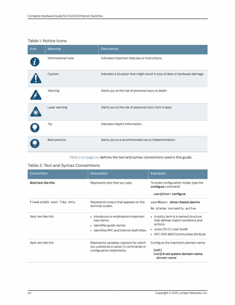
Table 1: Notice Icons
DescriptionMeaningIcon
Indicates important features or instructions.Informational note
Indicates a situation that might result in loss of data or hardware damage.Caution
Alerts you to the risk of personal injury or death.Warning
Alerts you to the risk of personal injury from a laser.Laser warning
Indicates helpful information.Tip
Alerts you to a recommended use or implementation.Best practice
Table 2 on page xiv defines the text and syntax conventions used in this guide.
Table 2: Text and Syntax Conventions
ExamplesDescriptionConvention
To enter configuration mode, type theconfigure command:
user@host> configure
Represents text that you type.Bold text like this
user@host> show chassis alarms
No alarms currently active
Represents output that appears on theterminal screen.
Fixed-width text like this
• A policy term is a named structurethat defines match conditions andactions.
• Junos OS CLI User Guide
• RFC 1997,BGPCommunities Attribute
• Introduces or emphasizes importantnew terms.
• Identifies guide names.
• Identifies RFC and Internet draft titles.
Italic text like this
Configure themachine’s domain name:
[edit]root@# set system domain-namedomain-name
Represents variables (options for whichyou substitute a value) in commands orconfiguration statements.
Italic text like this
Copyright © 2015, Juniper Networks, Inc.xiv
Complete Hardware Guide for EX2200 Ethernet Switches
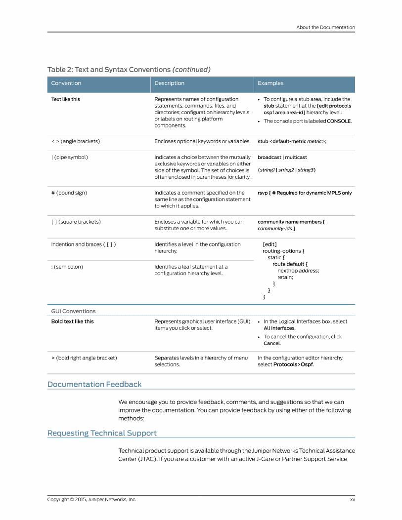
Table 2: Text and Syntax Conventions (continued)
ExamplesDescriptionConvention
• To configure a stub area, include thestub statement at the [edit protocolsospf area area-id] hierarchy level.
• Theconsoleport is labeledCONSOLE.
Represents names of configurationstatements, commands, files, anddirectories; configurationhierarchy levels;or labels on routing platformcomponents.
Text like this
stub <default-metricmetric>;Encloses optional keywords or variables.< > (angle brackets)
broadcast | multicast
(string1 | string2 | string3)
Indicates a choice between themutuallyexclusive keywords or variables on eitherside of the symbol. The set of choices isoften enclosed in parentheses for clarity.
| (pipe symbol)
rsvp { # Required for dynamicMPLS onlyIndicates a comment specified on thesame lineas theconfiguration statementto which it applies.
# (pound sign)
community namemembers [community-ids ]
Encloses a variable for which you cansubstitute one or more values.
[ ] (square brackets)
[edit]routing-options {static {route default {nexthop address;retain;
}}
}
Identifies a level in the configurationhierarchy.
Indention and braces ( { } )
Identifies a leaf statement at aconfiguration hierarchy level.
; (semicolon)
GUI Conventions
• In the Logical Interfaces box, selectAll Interfaces.
• To cancel the configuration, clickCancel.
Representsgraphicaluser interface(GUI)items you click or select.
Bold text like this
In the configuration editor hierarchy,select Protocols>Ospf.
Separates levels in a hierarchy of menuselections.
> (bold right angle bracket)
Documentation Feedback
We encourage you to provide feedback, comments, and suggestions so that we can
improve the documentation. You can provide feedback by using either of the following
methods:
Requesting Technical Support
Technical product support is available through the JuniperNetworksTechnicalAssistance
Center (JTAC). If you are a customer with an active J-Care or Partner Support Service
xvCopyright © 2015, Juniper Networks, Inc.
About the Documentation

support contract, or are covered under warranty, and need post-sales technical support,
you can access our tools and resources online or open a case with JTAC.
• JTAC policies—For a complete understanding of our JTAC procedures and policies,
review the JTAC User Guide located at
http://www.juniper.net/us/en/local/pdf/resource-guides/7100059-en.pdf.
• Product warranties—For product warranty information, visit
http://www.juniper.net/support/warranty/.
• JTAC hours of operation—The JTAC centers have resources available 24 hours a day,
7 days a week, 365 days a year.
Self-Help Online Tools and Resources
For quick and easy problem resolution, Juniper Networks has designed an online
self-service portal called the Customer Support Center (CSC) that provides youwith the
following features:
• Find CSC offerings: http://www.juniper.net/customers/support/
• Search for known bugs: http://www2.juniper.net/kb/
• Find product documentation: http://www.juniper.net/techpubs/
• Find solutions and answer questions using our Knowledge Base: http://kb.juniper.net/
• Download the latest versions of software and review release notes:
http://www.juniper.net/customers/csc/software/
• Search technical bulletins for relevant hardware and software notifications:
http://kb.juniper.net/InfoCenter/
• Join and participate in the Juniper Networks Community Forum:
http://www.juniper.net/company/communities/
• Open a case online in the CSC Case Management tool: http://www.juniper.net/cm/
Toverify serviceentitlementbyproduct serial number, useourSerialNumberEntitlement
(SNE) Tool: https://tools.juniper.net/SerialNumberEntitlementSearch/
Opening a Casewith JTAC
You can open a case with JTAC on theWeb or by telephone.
• Use the Case Management tool in the CSC at http://www.juniper.net/cm/.
• Call 1-888-314-JTAC (1-888-314-5822 toll-free in the USA, Canada, and Mexico).
For international or direct-dial options in countries without toll-free numbers, see
http://www.juniper.net/support/requesting-support.html.
Copyright © 2015, Juniper Networks, Inc.xvi
Complete Hardware Guide for EX2200 Ethernet Switches

PART 1
Switch and Components Overview andSpecifications
• EX2200 Switch Overview on page 3
• Component Descriptions on page 13
• Component Specifications on page 21
1Copyright © 2015, Juniper Networks, Inc.

Copyright © 2015, Juniper Networks, Inc.2
Complete Hardware Guide for EX2200 Ethernet Switches

CHAPTER 1
EX2200 Switch Overview
• EX2200 Switches Hardware Overview on page 3
• EX2200 Switch Models on page 9
• Chassis Physical Specifications for EX2200 Switches on page 9
• EX2200 Switch Hardware and CLI Terminology Mapping on page 10
EX2200 Switches Hardware Overview
Juniper Networks EX Series Ethernet Switches provide scalable connectivity for the
enterprise market, including branch offices, campus locations, and data centers. The
switches run the Juniper Networks Junos operating system (Junos OS), which provides
Layer 2 and Layer 3 switching, routing, and security services. The same Junos OS code
base that runs on EX Series switches also runs on all Juniper Networks M Series, MX
Series, and T Series routers and SRX Series Services Gateways.
Juniper Networks EX2200 Ethernet Switches provide connectivity for low-density
environments.
This topic describes:
• EX2200 Switches First View on page 3
• Uplink Ports on page 4
• Console Port on page 4
• Cable Guard on page 5
• Security Slots on page 5
• Power over Ethernet (PoE) Ports on page 5
• Front Panel of an EX2200 Switch on page 6
• Rear Panel of an EX2200 Switch on page 7
EX2200 Switches First View
EX2200 switches are available in models with 12 , 24, or 48 built-in network ports. The
compact, fanless model, EX2200-C switches have 12 network ports.
3Copyright © 2015, Juniper Networks, Inc.

EX2200 switches provide:
• Up to four uplink ports
• 12 (compact, fanlessmodel), 24, or 48 built-in network portswith 10/100/100BASE-T
Gigabit Ethernet connectors
• Virtual Chassis capability—You can connect up to four EX2200 switches (including
EX2200-C switches) together to form one unit that youmanage as a single chassis,
called a Virtual Chassis, starting in Junos OS Release 12.2.
• Power over Ethernet (PoE or PoE+) on all network ports (in PoE-capable models)
Uplink Ports
Each EX2200 switch except the EX2200-C switch model has four uplink ports that
support 1-gigabit small form-factor pluggable (SFP) transceivers for use with fiber
connections and copper connections.
EachEX2200-Cswitchhas twodual-purposeuplinkports. Eachdual uplinkport consists
of an RJ-45 port (in which you can connect a copper Ethernet cable) and an SFP port
(into which you can plug a transceiver). Only one of the ports can be active at a time. By
default, if you connect a copper Ethernet cable to the RJ-45 port, this port becomes the
active port provided that there is no connection made on the other port. If you plug a
transceiver into the SFP port, this port becomes the active port whether or not a copper
Ethernet cable is connected to the other port. You can change this default behavior by
explicitly configuring amedia type—copper or fiber—for the dual-purpose port using the
media-type command. For more information, see Configuring the Media Type on
Dual-Purpose Uplink Ports (CLI Procedure).
You can use an SFP uplink port connection between EX2200 switches to interconnect
the switches into an EX2200 Virtual Chassis. Youmust explicitly configure the SFP port
as a VCP. See Setting an Uplink Port on an EX Series Switch as a Virtual Chassis Port (CLI
Procedure).
For information about the supported optical and copper interfaces, see “Pluggable
Transceivers Supported on EX2200 Switches” on page 26.
Console Port
Each EX2200 switch except the EX2200-C switchmodel has an RJ-45 console port that
accepts a cable with RJ-45 connector.
The EX2200-C switch has two console ports: an RJ-45 port and aMini-USBType-B port.
The RJ-45 console port accepts a cable with an RJ-45 connector and the Mini-USB
Type-B console port accepts a Mini-B plug (5-pin) connector to connect to the console
management device. The switch activates only one console port at a time, either the
RJ-45 console port or the Mini USB type-B console port. By default, the RJ-45 port is the
active console port and the Mini-USB Type-B port is the passive console port. You can
change thedefault settingofaconsoleportusing theport-typecommand.SeeConfiguring
the Console Port Type (CLI Procedure).
Copyright © 2015, Juniper Networks, Inc.4
Complete Hardware Guide for EX2200 Ethernet Switches
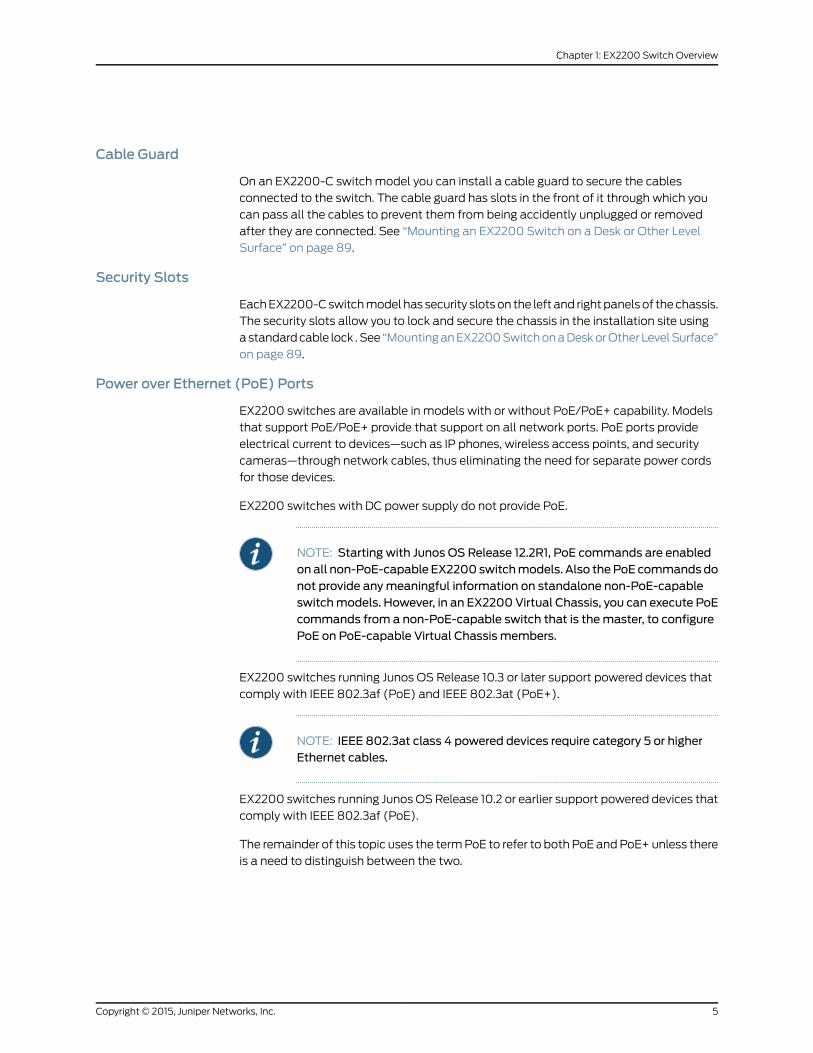
Cable Guard
On an EX2200-C switch model you can install a cable guard to secure the cables
connected to the switch. The cable guard has slots in the front of it through which you
can pass all the cables to prevent them from being accidently unplugged or removed
after they are connected. See “Mounting an EX2200 Switch on a Desk or Other Level
Surface” on page 89.
Security Slots
EachEX2200-Cswitchmodel has security slotson the left and rightpanelsof thechassis.
The security slots allow you to lock and secure the chassis in the installation site using
astandardcable lock .See “MountinganEX2200SwitchonaDeskorOther LevelSurface”
on page 89.
Power over Ethernet (PoE) Ports
EX2200 switches are available in models with or without PoE/PoE+ capability. Models
that support PoE/PoE+ provide that support on all network ports. PoE ports provide
electrical current to devices—such as IP phones, wireless access points, and security
cameras—through network cables, thus eliminating the need for separate power cords
for those devices.
EX2200 switches with DC power supply do not provide PoE.
NOTE: Starting with Junos OS Release 12.2R1, PoE commands are enabledon all non-PoE-capable EX2200 switchmodels. Also thePoE commands donot provide anymeaningful information on standalone non-PoE-capableswitchmodels. However, in an EX2200Virtual Chassis, you can execute PoEcommands from a non-PoE-capable switch that is themaster, to configurePoE on PoE-capable Virtual Chassis members.
EX2200 switches running Junos OS Release 10.3 or later support powered devices that
comply with IEEE 802.3af (PoE) and IEEE 802.3at (PoE+).
NOTE: IEEE 802.3at class 4 powered devices require category 5 or higherEthernet cables.
EX2200 switches running Junos OSRelease 10.2 or earlier support powered devices that
comply with IEEE 802.3af (PoE).
The remainder of this topic uses the termPoE to refer to both PoE andPoE+ unless there
is a need to distinguish between the two.
5Copyright © 2015, Juniper Networks, Inc.
Chapter 1: EX2200 Switch Overview

Front Panel of an EX2200 Switch
The front panel of an EX2200 switch except the EX2200-C switch models consists of
the following components:
• Network ports—depending on the switch model, either of:
• 24 or 48 10/100/1000BASE-T Gigabit Ethernet ports, with Power over Ethernet
(PoE) not available in EX2200-24T, EX2200-24T-DC, and EX2200-48Tmodels
• 24 or 48 10/100/1000BASE-T Gigabit Ethernet ports, with Power over Ethernet
(PoE) available in EX2200-24P and EX2200-48Pmodels
• 4 built-in SFP uplink ports. You can use these ports to forward network traffic or
configure them into Virtual Chassis ports (VCPs) to interconnect EX2200 switches
into a Virtual Chassis.
• 2 chassis status LEDs
• 4 port status mode LEDs
• Mode button
Figure 1 on page 6 shows the front panel of an EX2200 switch with 48 Gigabit Ethernet
ports. Figure 2 on page 6 shows the front panel of an EX2200 switch with 24 Gigabit
Ethernet ports.
Figure 1: Front Panel of anEX2200Switchwith 48Gigabit Ethernet Ports
0 1 2 3 4 5 6 7 8 9 10 11 12 13 14 15 1617 1819 2021 22 23 2425 2627 2829 3031 3233 34 35 3637 3839 4041 4243 4445
0 1 2
SYSALM
SPD
DX
EN
POE
3
46 47
Networkports
Port status mode LEDs
ModebuttonSFP
uplinkports
ChassisstatusLEDs
g027
000
Figure 2: FrontPanel of anEX2200Switchwith 24Gigabit EthernetPorts
0 1 2 3 4 5 6 7 8 9 10 11 12 13 14 15 1617 1819 2021 22 23
0 1 2
SYSALM
SPD
DX
EN
POE
3
Networkports
ChassisstatusLEDs
g027
002
SFPuplinkports
Port status mode LEDs
Modebutton
The front panel of an EX2200-C switch consists of the following components:
• Network ports—depending on the switch model, either of:
Copyright © 2015, Juniper Networks, Inc.6
Complete Hardware Guide for EX2200 Ethernet Switches
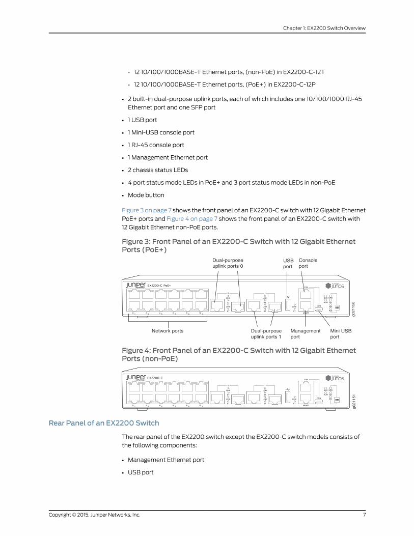
• 12 10/100/1000BASE-T Ethernet ports, (non-PoE) in EX2200-C-12T
• 12 10/100/1000BASE-T Ethernet ports, (PoE+) in EX2200-C-12P
• 2 built-in dual-purpose uplink ports, each of which includes one 10/100/1000 RJ-45
Ethernet port and one SFP port
• 1 USB port
• 1 Mini-USB console port
• 1 RJ-45 console port
• 1 Management Ethernet port
• 2 chassis status LEDs
• 4 port status mode LEDs in PoE+ and 3 port status mode LEDs in non-PoE
• Mode button
Figure 3 on page 7 shows the front panel of an EX2200-C switchwith 12 Gigabit Ethernet
PoE+ ports and Figure 4 on page 7 shows the front panel of an EX2200-C switch with
12 Gigabit Ethernet non-PoE ports.
Figure 3: Front Panel of an EX2200-C Switch with 12 Gigabit EthernetPorts (PoE+)
g021150
Network ports
Dual-purposeuplink ports 0
Dual-purposeuplink ports 1
Consoleport
USBport
Mini USBport
Managementport
Figure 4: Front Panel of an EX2200-C Switch with 12 Gigabit EthernetPorts (non-PoE)
g021151
Rear Panel of an EX2200 Switch
The rear panel of the EX2200 switch except the EX2200-C switch models consists of
the following components:
• Management Ethernet port
• USB port
7Copyright © 2015, Juniper Networks, Inc.
Chapter 1: EX2200 Switch Overview

• Console port
• Protective earthing terminal
• ESD point
• Air exhaust
• Serial number ID label
• AC power cord inlet or DC power terminals
Figure 5 on page 8 shows the rear panel of an EX2200 switch with an AC power supply.
All EX2200 switches except the EX2200-C switch model have three exhaust openings
on the rear panel. The two exhaust openings on the left have fans behind them and are
open. The exhaust opening on the right is open on Power over Ethernet (PoE) models
and closed on non-PoEmodels. On PoEmodels, this opening exhausts the air from the
fan at the air intake for the power supply on the side panel.
The power cord retainer clips extend out of the chassis by 3 in.
Figure 5: Rear Panel of an EX2200 Switch with AC Power Supply
g027
001
USBport
ManagementEthernet port
Consoleport
Protectiveearthing terminal
Air exhaust without fan(closed on non-PoE models)
Air exhaustwith fan
AC powercord inlet
ESDpoint
EX2200-24-4G REV: X1
750-026464 REV: X3
MAC: 00:23:9C:oE:19:00
Mfg. Date20090227
MADE IN CHINA
Serial numberID label
Air intake with fan for power supply(fan on PoE models only)
The rear panel of an EX2200-C switch consists of the following components:
• Protective earthing terminal
• ESD point
• Serial number ID label
• AC power cord inlet
• Heatsink-only in PoE+models
Figure 6 on page 9 shows the rear panel of an EX2200-C-12P switch with heatsink.
EX2200-C switches being fanless models have no exhaust openings. The switch has
vents on the top and on both the sides of the chassis. The PoE+models have heatsink
installed in the rear panel to dissipate the heat, while non-PoEmodels have no heatsink.
Copyright © 2015, Juniper Networks, Inc.8
Complete Hardware Guide for EX2200 Ethernet Switches
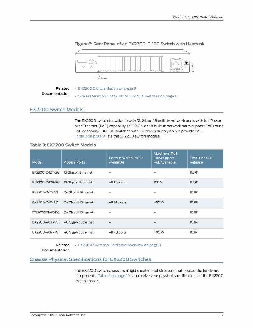
Figure 6: Rear Panel of an EX2200-C-12P Switch with Heatsink
g021152
Heatsink
RelatedDocumentation
EX2200 Switch Models on page 9•
• Site Preparation Checklist for EX2200 Switches on page 61
EX2200 SwitchModels
The EX2200 switch is available with 12, 24, or 48 built-in network ports with full Power
over Ethernet (PoE) capability (all 12, 24, or 48 built-in network ports support PoE) or no
PoE capability. EX2200 switches with DC power supply do not provide PoE.
Table 3 on page 9 lists the EX2200 switch models.
Table 3: EX2200 SwitchModels
First Junos OSRelease
MaximumPoEPower pportPoEAvailable
Ports inWhich PoE IsAvailableAccess PortsModel
11.3R1––12 Gigabit EthernetEX2200-C-12T-2G
11.3R1100WAll 12 ports12 Gigabit EthernetEX2200-C-12P-2G
10.1R1––24 Gigabit EthernetEX2200-24T-4G
10.1R1405WAll 24 ports24 Gigabit EthernetEX2200-24P-4G
10.1R1––24 Gigabit EthernetEX2200-24T-4G-DC
10.1R1––48 Gigabit EthernetEX2200-48T-4G
10.1R1405WAll 48 ports48 Gigabit EthernetEX2200-48P-4G
RelatedDocumentation
EX2200 Switches Hardware Overview on page 3•
Chassis Physical Specifications for EX2200 Switches
The EX2200 switch chassis is a rigid sheet-metal structure that houses the hardware
components. Table 4 on page 10 summarizes the physical specifications of the EX2200
switch chassis.
9Copyright © 2015, Juniper Networks, Inc.
Chapter 1: EX2200 Switch Overview
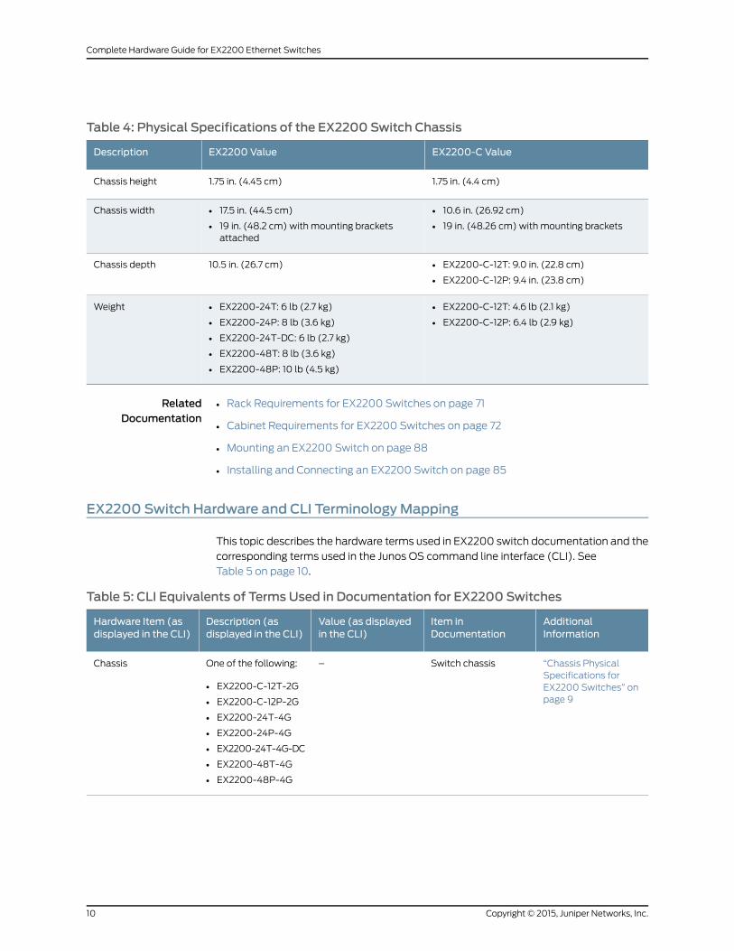
Table 4: Physical Specifications of the EX2200 Switch Chassis
EX2200-C ValueEX2200 ValueDescription
1.75 in. (4.4 cm)1.75 in. (4.45 cm)Chassis height
• 10.6 in. (26.92 cm)
• 19 in. (48.26 cm) with mounting brackets
• 17.5 in. (44.5 cm)
• 19 in. (48.2 cm) with mounting bracketsattached
Chassis width
• EX2200-C-12T: 9.0 in. (22.8 cm)
• EX2200-C-12P: 9.4 in. (23.8 cm)
10.5 in. (26.7 cm)Chassis depth
• EX2200-C-12T: 4.6 lb (2.1 kg)
• EX2200-C-12P: 6.4 lb (2.9 kg)
• EX2200-24T: 6 lb (2.7 kg)
• EX2200-24P: 8 lb (3.6 kg)
• EX2200-24T-DC: 6 lb (2.7 kg)
• EX2200-48T: 8 lb (3.6 kg)
• EX2200-48P: 10 lb (4.5 kg)
Weight
RelatedDocumentation
Rack Requirements for EX2200 Switches on page 71•
• Cabinet Requirements for EX2200 Switches on page 72
• Mounting an EX2200 Switch on page 88
• Installing and Connecting an EX2200 Switch on page 85
EX2200 Switch Hardware and CLI TerminologyMapping
This topic describes the hardware terms used in EX2200 switch documentation and the
corresponding terms used in the Junos OS command line interface (CLI). See
Table 5 on page 10.
Table 5: CLI Equivalents of Terms Used in Documentation for EX2200 Switches
AdditionalInformation
Item inDocumentation
Value (as displayedin the CLI)
Description (asdisplayed in the CLI)
Hardware Item (asdisplayed in the CLI)
“Chassis PhysicalSpecifications forEX2200 Switches” onpage 9
Switch chassis–One of the following:
• EX2200-C-12T-2G
• EX2200-C-12P-2G
• EX2200-24T-4G
• EX2200-24P-4G
• EX2200-24T-4G-DC
• EX2200-48T-4G
• EX2200-48P-4G
Chassis
Copyright © 2015, Juniper Networks, Inc.10
Complete Hardware Guide for EX2200 Ethernet Switches
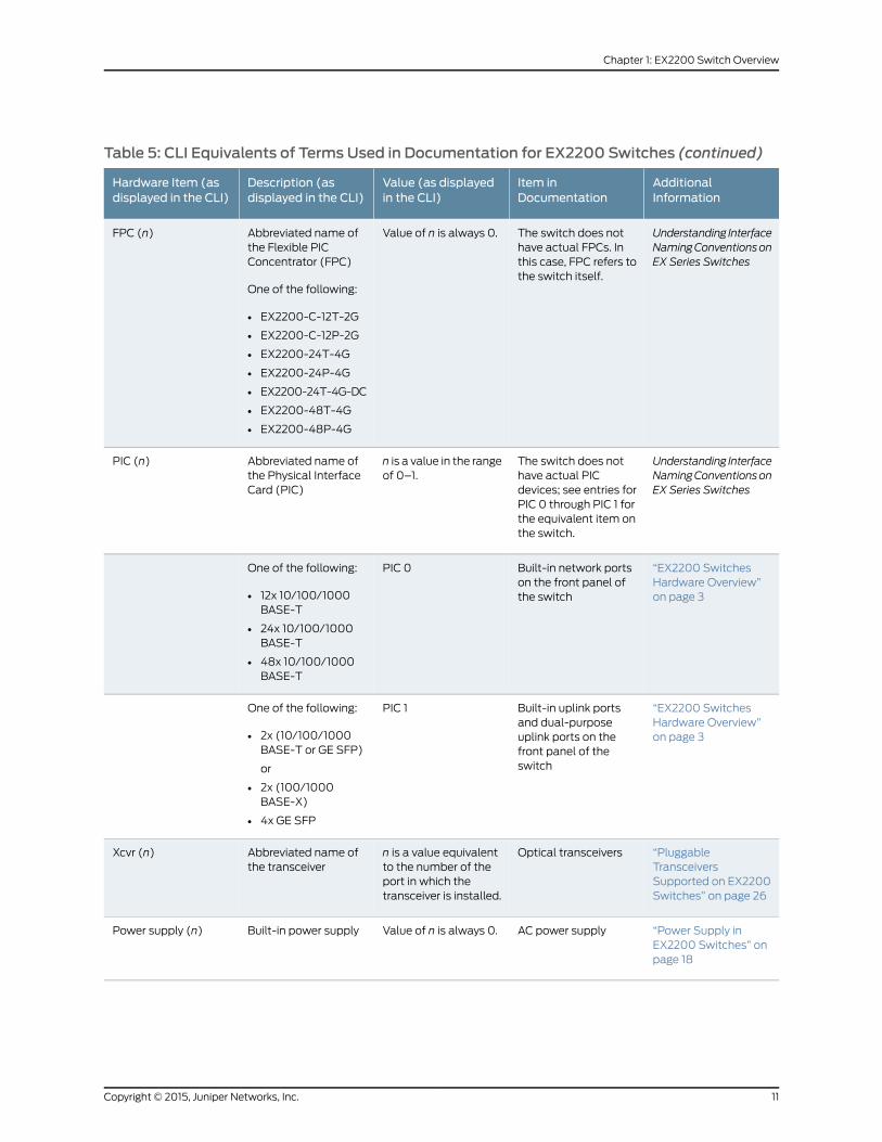
Table 5: CLI Equivalents of Terms Used in Documentation for EX2200 Switches (continued)
AdditionalInformation
Item inDocumentation
Value (as displayedin the CLI)
Description (asdisplayed in the CLI)
Hardware Item (asdisplayed in the CLI)
Understanding InterfaceNamingConventionsonEX Series Switches
The switch does nothave actual FPCs. Inthis case, FPC refers tothe switch itself.
Value of n is always 0.Abbreviated name ofthe Flexible PICConcentrator (FPC)
One of the following:
• EX2200-C-12T-2G
• EX2200-C-12P-2G
• EX2200-24T-4G
• EX2200-24P-4G
• EX2200-24T-4G-DC
• EX2200-48T-4G
• EX2200-48P-4G
FPC (n)
Understanding InterfaceNamingConventionsonEX Series Switches
The switch does nothave actual PICdevices; see entries forPIC 0 through PIC 1 forthe equivalent item onthe switch.
n is a value in the rangeof 0–1.
Abbreviated name ofthe Physical InterfaceCard (PIC)
PIC (n)
“EX2200 SwitchesHardware Overview”on page 3
Built-in network portson the front panel ofthe switch
PIC 0One of the following:
• 12x 10/100/1000BASE-T
• 24x 10/100/1000BASE-T
• 48x 10/100/1000BASE-T
“EX2200 SwitchesHardware Overview”on page 3
Built-in uplink portsand dual-purposeuplink ports on thefront panel of theswitch
PIC 1One of the following:
• 2x (10/100/1000BASE-T or GE SFP)
or
• 2x (100/1000BASE-X)
• 4x GE SFP
“PluggableTransceiversSupported on EX2200Switches” on page 26
Optical transceiversn is a value equivalentto the number of theport in which thetransceiver is installed.
Abbreviated name ofthe transceiver
Xcvr (n)
“Power Supply inEX2200 Switches” onpage 18
AC power supplyValue of n is always 0.Built-in power supplyPower supply (n)
11Copyright © 2015, Juniper Networks, Inc.
Chapter 1: EX2200 Switch Overview
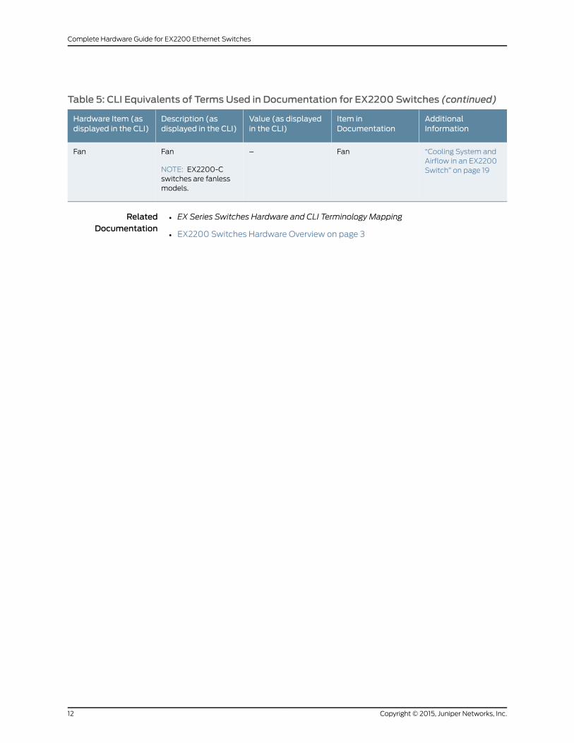
Table 5: CLI Equivalents of Terms Used in Documentation for EX2200 Switches (continued)
AdditionalInformation
Item inDocumentation
Value (as displayedin the CLI)
Description (asdisplayed in the CLI)
Hardware Item (asdisplayed in the CLI)
“Cooling System andAirflow in an EX2200Switch” on page 19
Fan–Fan
NOTE: EX2200-Cswitches are fanlessmodels.
Fan
RelatedDocumentation
• EX Series Switches Hardware and CLI Terminology Mapping
• EX2200 Switches Hardware Overview on page 3
Copyright © 2015, Juniper Networks, Inc.12
Complete Hardware Guide for EX2200 Ethernet Switches
CHAPTER 2
Component Descriptions
• Chassis Status LEDs in EX2200 Switches on page 13
• Network Port and Uplink Port LEDs in EX2200 Switches on page 14
• Management Port LEDs in EX2200 Switches on page 17
• Power Supply in EX2200 Switches on page 18
• Cooling System and Airflow in an EX2200 Switch on page 19
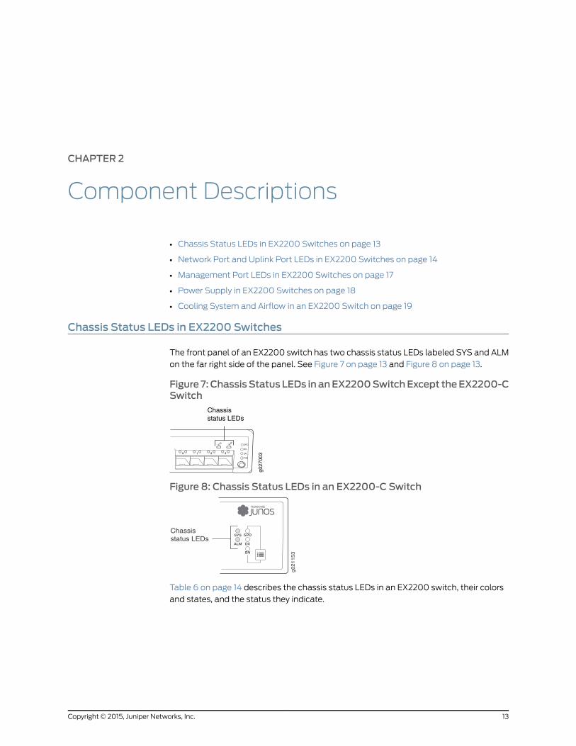
Chassis Status LEDs in EX2200 Switches
The front panel of an EX2200 switch has two chassis status LEDs labeled SYS and ALM
on the far right side of the panel. See Figure 7 on page 13 and Figure 8 on page 13.
Figure 7: ChassisStatus LEDs in anEX2200SwitchExcept theEX2200-CSwitch
g027
0030 1 2
SYSALM
SPD
DX
EN
POE
3
Chassisstatus LEDs
Figure 8: Chassis Status LEDs in an EX2200-C Switch
g021153
Chassisstatus LEDs
Table 6 on page 14 describes the chassis status LEDs in an EX2200 switch, their colors
and states, and the status they indicate.
13Copyright © 2015, Juniper Networks, Inc.
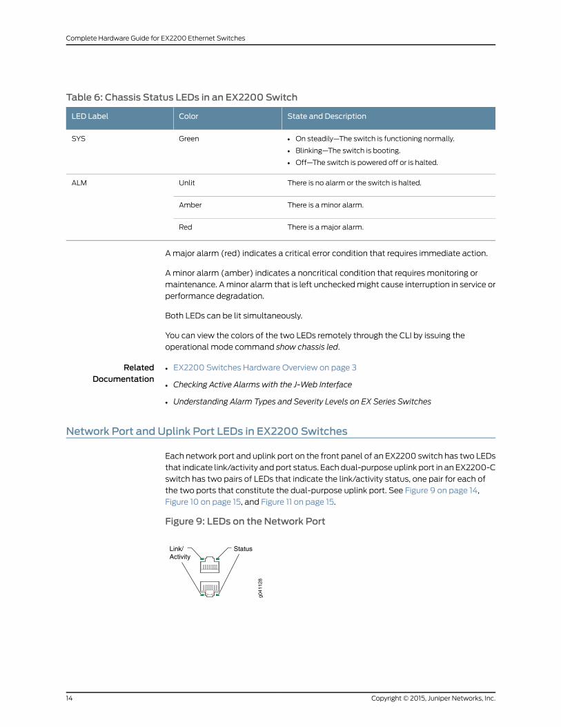
Table 6: Chassis Status LEDs in an EX2200 Switch
State and DescriptionColorLED Label
• On steadily—The switch is functioning normally.
• Blinking—The switch is booting.
• Off—The switch is powered off or is halted.
GreenSYS
There is no alarm or the switch is halted.UnlitALM
There is a minor alarm.Amber
There is a major alarm.Red
Amajor alarm (red) indicates a critical error condition that requires immediate action.
A minor alarm (amber) indicates a noncritical condition that requires monitoring or
maintenance. Aminor alarm that is left uncheckedmight cause interruption in service or
performance degradation.
Both LEDs can be lit simultaneously.
You can view the colors of the two LEDs remotely through the CLI by issuing the
operational mode command show chassis led.
RelatedDocumentation
EX2200 Switches Hardware Overview on page 3•
• Checking Active Alarms with the J-Web Interface
• Understanding Alarm Types and Severity Levels on EX Series Switches
Network Port and Uplink Port LEDs in EX2200 Switches
Each network port and uplink port on the front panel of an EX2200 switch has two LEDs
that indicate link/activity and port status. Each dual-purpose uplink port in an EX2200-C
switch has two pairs of LEDs that indicate the link/activity status, one pair for each of
the two ports that constitute the dual-purpose uplink port. See Figure 9 on page 14,
Figure 10 on page 15, and Figure 11 on page 15.
Figure 9: LEDs on the Network Port
g041
128
Link/Activity
Status
Copyright © 2015, Juniper Networks, Inc.14
Complete Hardware Guide for EX2200 Ethernet Switches
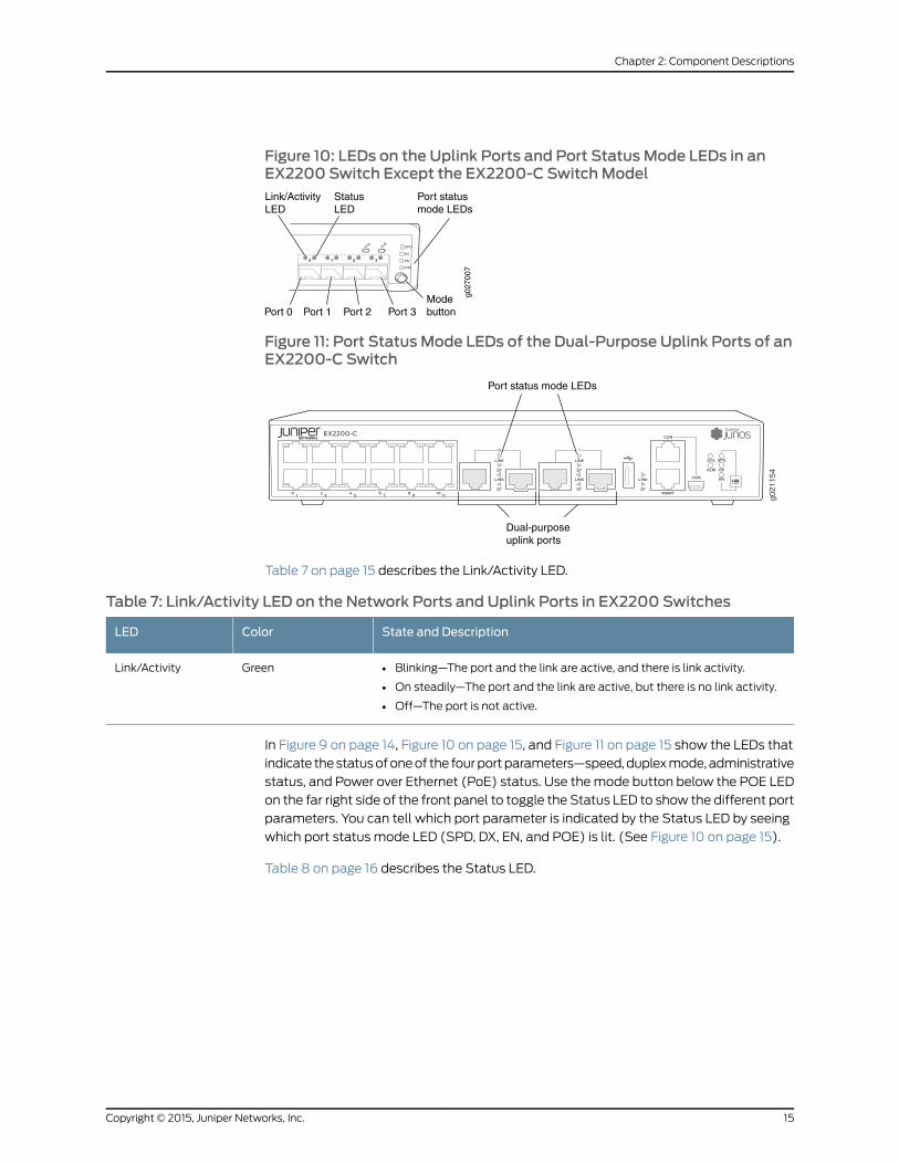
Figure 10: LEDs on the Uplink Ports and Port StatusMode LEDs in anEX2200 Switch Except the EX2200-C SwitchModel
g027
007
0 1 2
SYSALM
SPD
DX
EN
POE
3
Port 1 Port 2 Port 3Modebutton
Link/ActivityLED
StatusLED
Port 0
Port statusmode LEDs
Figure 11: Port StatusMode LEDs of the Dual-Purpose Uplink Ports of anEX2200-C Switch
g021154
Dual-purposeuplink ports
Port status mode LEDs
Table 7 on page 15 describes the Link/Activity LED.
Table 7: Link/Activity LED on the Network Ports and Uplink Ports in EX2200 Switches
State and DescriptionColorLED
• Blinking—The port and the link are active, and there is link activity.
• On steadily—The port and the link are active, but there is no link activity.
• Off—The port is not active.
GreenLink/Activity
In Figure 9 on page 14, Figure 10 on page 15, and Figure 11 on page 15 show the LEDs that
indicate thestatusofoneof the fourportparameters—speed,duplexmode,administrative
status, and Power over Ethernet (PoE) status. Use themode button below the POE LED
on the far right side of the front panel to toggle the Status LED to show the different port
parameters. You can tell which port parameter is indicated by the Status LED by seeing
which port status mode LED (SPD, DX, EN, and POE) is lit. (See Figure 10 on page 15).
Table 8 on page 16 describes the Status LED.
15Copyright © 2015, Juniper Networks, Inc.
Chapter 2: Component Descriptions
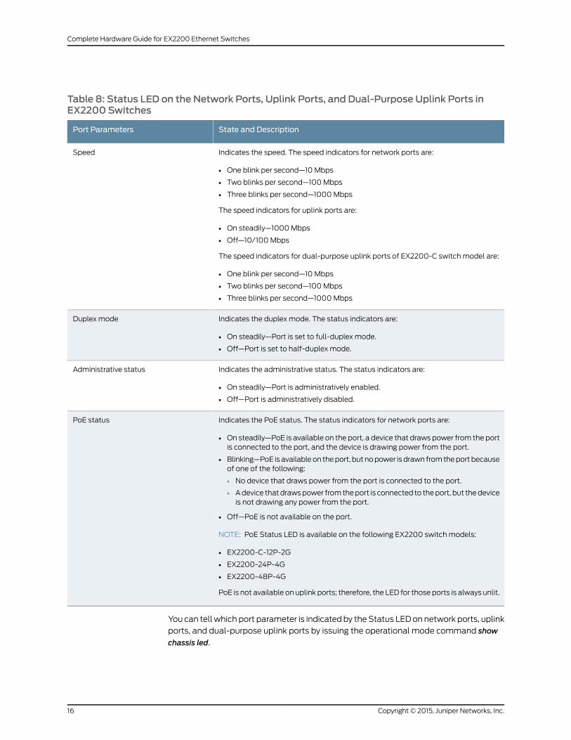
Table 8: Status LED on the Network Ports, Uplink Ports, and Dual-Purpose Uplink Ports inEX2200 Switches
State and DescriptionPort Parameters
Indicates the speed. The speed indicators for network ports are:
• One blink per second—10 Mbps
• Two blinks per second—100Mbps
• Three blinks per second—1000Mbps
The speed indicators for uplink ports are:
• On steadily—1000Mbps
• Off—10/100Mbps
The speed indicators for dual-purpose uplink ports of EX2200-C switch model are:
• One blink per second—10 Mbps
• Two blinks per second—100Mbps
• Three blinks per second—1000Mbps
Speed
Indicates the duplex mode. The status indicators are:
• On steadily—Port is set to full-duplex mode.
• Off—Port is set to half-duplex mode.
Duplex mode
Indicates the administrative status. The status indicators are:
• On steadily—Port is administratively enabled.
• Off—Port is administratively disabled.
Administrative status
Indicates the PoE status. The status indicators for network ports are:
• On steadily—PoE is available on the port, a device that draws power from the portis connected to the port, and the device is drawing power from the port.
• Blinking—PoE isavailableon theport, butnopower isdrawn fromtheportbecauseof one of the following:
• No device that draws power from the port is connected to the port.
• Adevice thatdrawspower fromtheport is connected to theport, but thedeviceis not drawing any power from the port.
• Off—PoE is not available on the port.
NOTE: PoE Status LED is available on the following EX2200 switch models:
• EX2200-C-12P-2G
• EX2200-24P-4G
• EX2200-48P-4G
PoE is not available on uplink ports; therefore, the LED for those ports is always unlit.
PoE status
You can tell which port parameter is indicated by theStatus LEDon network ports, uplink
ports, and dual-purpose uplink ports by issuing the operational mode command show
chassis led.
Copyright © 2015, Juniper Networks, Inc.16
Complete Hardware Guide for EX2200 Ethernet Switches
RelatedDocumentation
EX2200 Switches Hardware Overview on page 3•
• Configuring Gigabit Ethernet Interfaces (CLI Procedure)
• Configuring Gigabit Ethernet Interfaces (J-Web Procedure)
Management Port LEDs in EX2200 Switches
Themanagement port on an EX2200 switch has two LEDs that indicate link/activity and
port status. The EX2200 switches except the EX2200-C switch models have the
managementport on the rear panel and theEX2200-Cswitchhas themanagementport
on the front panel. See Figure 12 on page 17 and Figure 13 on page 17.
Figure 12: LEDs on theManagement Port on an EX2200 Switch Exceptthe EX2200-C SwitchModel
g027
006
Link/ActivityLED
StatusLED
Figure 13: LEDs on theManagement Port on an EX2200-C Switch
g021155
StatusLED
Link/ActivityLED
Table 9 on page 17 describes the Link/Activity LED.
Table 9: Link/Activity LED on theManagement Port on EX2200 Switches
State and DescriptionColorLED
• Blinking—The port and the link are active, and there is linkactivity.
• On steadily—The port and the link are active, but there is nolink activity.
• Off—The port is not active.
GreenLink/Activity
Table 10 on page 18 describes the Status LED.
17Copyright © 2015, Juniper Networks, Inc.
Chapter 2: Component Descriptions
Table 10: Status LED on theManagement Port on EX2200 Switches
State and DescriptionColorLED
Indicates the speed. The speed indicators are:
• One blink per second—10 Mbps
• Two blinks per second—100Mbps
GreenStatus
RelatedDocumentation
Connecting a Switch to a Network for Out-of-Band Management on page 127•
Power Supply in EX2200 Switches
The power supply in EX2200 switches is built in along the rear panel of the chassis, with
an AC power cord inlet or DC power terminals on the rear panel to connect power to the
switch.
Table 11 on page 18 lists the power consumed by each EX2200 switch model. The
maximum power available on a PoE port is 30W for switches running Junos OS Release
10.3 or later and 15.4W for switches running Junos OS Release 10.2 or earlier.
Table 11: Power Consumed by EX2200 Switches
MaximumPoE PowerAvailable
MaximumPowerConsumed by the Switch
Number of PoE-EnabledPortsModel Number
–30W–EX2200-C-12T
100W30W (when no PoE power isdrawn)
12EX2200-C-12P
–50W–EX2200-24T
405W60W (when no PoE power isdrawn)
24EX2200-24P
–50W–EX2200-24T-DC
–76W–EX2200-48T
405W91W (when no PoE power isdrawn)
48EX2200-48P
RelatedDocumentation
AC Power Cord Specifications for EX2200 Switches on page 80•
• EX2200 Switches Hardware Overview on page 3
• Power Specifications for EX2200 Switches on page 79
• Connecting AC Power to an EX2200 Switch on page 123
• Connecting DC Power to an EX2200 Switch on page 125
Copyright © 2015, Juniper Networks, Inc.18
Complete Hardware Guide for EX2200 Ethernet Switches
• Connecting Earth Ground to an EX Series Switch on page 117
Cooling System and Airflow in an EX2200 Switch
Thecoolingsystem inEX2200switches, exceptEX2200-C, thecompact, fanlessmodels,
consists of two fansalong the rear of thechassis thatprovide side-to-rear chassis cooling.
In the PoEmodels of these switches, there is an additional fan in the power supply.
In the EX2200-C switch the cooling is done by the vents on top and sides of the chassis
in non-PoEmodels and by heatsinks in PoE+models. Do not block the vents on the
chassis. Doing this can lead to overheating of the switch chassis
This topic describes:
• Airflow Direction in Non-PoE Models of EX2200 Switches, Except for the EX2200-C
Models on page 19
• Airflow Direction in PoE Models of EX2200 switches, Except for the EX2200-C
Models on page 20
Airflow Direction in Non-PoEModels of EX2200 Switches, Except for the EX2200-CModels
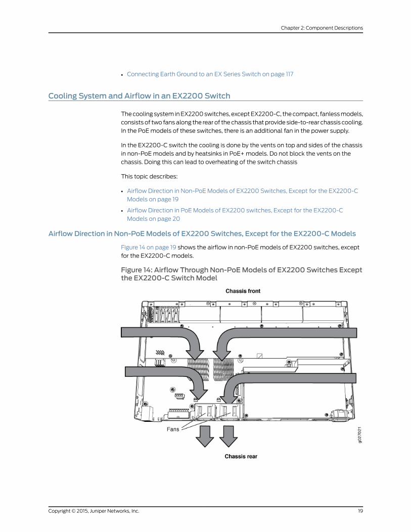
Figure 14 on page 19 shows the airflow in non-PoEmodels of EX2200 switches, except
for the EX2200-Cmodels.
Figure 14: Airflow Through Non-PoEModels of EX2200 Switches Exceptthe EX2200-C SwitchModel
19Copyright © 2015, Juniper Networks, Inc.
Chapter 2: Component Descriptions
Airflow Direction in PoEModels of EX2200 switches, Except for the EX2200-CModels
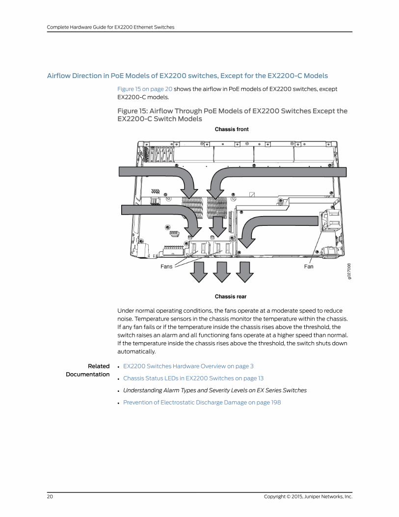
Figure 15 on page 20 shows the airflow in PoEmodels of EX2200 switches, except
EX2200-Cmodels.
Figure 15: Airflow Through PoEModels of EX2200 Switches Except theEX2200-C SwitchModels
Under normal operating conditions, the fans operate at a moderate speed to reduce
noise. Temperature sensors in the chassis monitor the temperature within the chassis.
If any fan fails or if the temperature inside the chassis rises above the threshold, the
switch raises an alarm and all functioning fans operate at a higher speed than normal.
If the temperature inside the chassis rises above the threshold, the switch shuts down
automatically.
RelatedDocumentation
• EX2200 Switches Hardware Overview on page 3
• Chassis Status LEDs in EX2200 Switches on page 13
• Understanding Alarm Types and Severity Levels on EX Series Switches
• Prevention of Electrostatic Discharge Damage on page 198
Copyright © 2015, Juniper Networks, Inc.20
Complete Hardware Guide for EX2200 Ethernet Switches

CHAPTER 3
Component Specifications
• USB Port Specifications for an EX Series Switch on page 21
• Mini-USB Port Specifications for an EX2200 Switch on page 22
• Network Port Connector Pinout Information for an EX2200 Switch on page 23
• Console Port Connector Pinout Information for an EX Series Switch on page 23
• RJ-45 to DB-9 Serial Port Adapter Pinout Information for a Switch on page 25
• Management Port Connector Pinout Information for an EX2200 Switch on page 25
• Pluggable Transceivers Supported on EX2200 Switches on page 26
USB Port Specifications for an EX Series Switch
The following Juniper Networks USB flash drives have been tested and are officially
supported for the USB port on all EX Series switches:
• RE-USB-1G-S
• RE-USB-2G-S
• RE-USB-4G-S
CAUTION: Any USBmemory product not listed as supported for EX Seriesswitches has not been tested by Juniper Networks. The use of anyunsupported USBmemory product could expose your EX Series switch tounpredictablebehavior. JuniperNetworksTechnicalAssistanceCenter (JTAC)can provide only limited support for issues related to unsupported hardware.We strongly recommend that you use only supported USB flash drives.
All USB flash drives used on EX Series switches must have the following features:
• USB 2.0 or later.
• Formatted with a FAT or MS-DOS file system.
• If the switch is running Junos OS Release 9.5 or earlier, the formatting methodmust
use amaster boot record. Microsoft Windows formatting, by default, does not use a
master boot record. See the documentation for your USB flash drive for information
about how your USB flash drive is formatted.
21Copyright © 2015, Juniper Networks, Inc.
RelatedDocumentation
EX2200 Switches Hardware Overview on page 3•
• Rear Panel of an EX3200 Switch
• Rear Panel of an EX3300 Switch
• Rear Panel of an EX4200 Switch
• EX4300 Switches Hardware Overview
• Front Panel of an EX4500 Switch
• Management Panel of an EX4600 Switch
• EX4550 Switches Hardware Overview
• Switch Fabric and Routing Engine (SRE) Module in an EX6200 Switch
• Switch Fabric and Routing Engine (SRE) Module in an EX8208 Switch
• Routing Engine (RE) Module in an EX8216 Switch
• Routing Engine Module in an EX9200 Switch
• Booting an EX Series Switch Using a Software Package Stored on a USB Flash Drive
Mini-USB Port Specifications for an EX2200 Switch
TheEX2200-Cswitch, the compact, fanlessmodel, has twomanagement consoleports:
an RJ-45 port, and a Mini-USB Type-B port.
By default, the RJ-45 port is set as the active console port. It can display all the early boot
and low-level message output and you can access the switch through this port in the
debugger prompt. TheMini-USBType-Bport is the passive console port. You can change
the status of the port to active or passive using the port-type configuration statement.
See Configuring the Console Port Type (CLI Procedure).).
The Mini-USB Type-B console port uses a Mini-B plug (5-pin) connector to connect to
a consolemanagement device. The default baud rate for the console port is 9600 baud.
Table 12 on page 22 provides the pinout information of the Mini-USB Type-B console
port.
Table 12: Mini-USB Type-B Console Port Pinout Information for EX2200-C Switches
DescriptionSignalPin
+5 VDCVCC1
Data -D-2
Data +D+3
May be N/C, GND or used as an attached device presence indicatorN/CX
GroundGND4
Copyright © 2015, Juniper Networks, Inc.22
Complete Hardware Guide for EX2200 Ethernet Switches
RelatedDocumentation
See EX2200 Switches Hardware Overview on page 3 for port location.•
• Configuring the Console Port Type (CLI Procedure)
Network Port Connector Pinout Information for an EX2200 Switch
A network port on an EX2200 switch uses an RJ-45 connector to connect to a device.
The port uses an autosensing RJ-45 connector to support a 10/100/1000Base-T
connection. Two LEDs on the port indicate link/activity on the port and the port status.
See “Network Port and Uplink Port LEDs in EX2200 Switches” on page 14.
Table 13 on page 23 provides the pinout information for the RJ-45 connector. An RJ-45
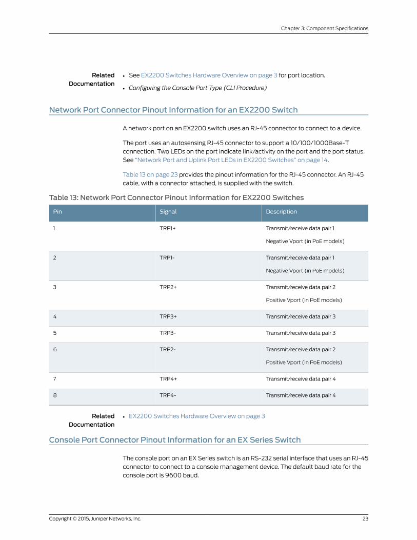
cable, with a connector attached, is supplied with the switch.
Table 13: Network Port Connector Pinout Information for EX2200 Switches
DescriptionSignalPin
Transmit/receive data pair 1
Negative Vport (in PoEmodels)
TRP1+1
Transmit/receive data pair 1
Negative Vport (in PoEmodels)
TRP1-2
Transmit/receive data pair 2
Positive Vport (in PoEmodels)
TRP2+3
Transmit/receive data pair 3TRP3+4
Transmit/receive data pair 3TRP3-5
Transmit/receive data pair 2
Positive Vport (in PoEmodels)
TRP2-6
Transmit/receive data pair 4TRP4+7
Transmit/receive data pair 4TRP4-8
RelatedDocumentation
EX2200 Switches Hardware Overview on page 3•
Console Port Connector Pinout Information for an EX Series Switch
The console port on an EX Series switch is an RS-232 serial interface that uses an RJ-45
connector to connect to a console management device. The default baud rate for the
console port is 9600 baud.
23Copyright © 2015, Juniper Networks, Inc.
Chapter 3: Component Specifications
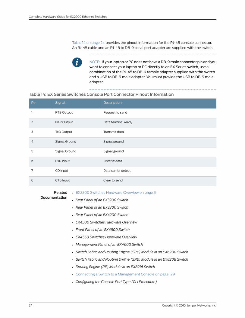
Table 14 on page 24 provides the pinout information for the RJ-45 console connector.
An RJ-45 cable and an RJ-45 to DB-9 serial port adapter are supplied with the switch.
NOTE: If your laptopor PCdoes not have aDB-9male connector pin and youwant to connect your laptop or PC directly to an EX Series switch, use acombination of the RJ-45 to DB-9 female adapter supplied with the switchand a USB to DB-9male adapter. Youmust provide the USB to DB-9maleadapter.
Table 14: EX Series Switches Console Port Connector Pinout Information
DescriptionSignalPin
Request to sendRTS Output1
Data terminal readyDTR Output2
Transmit dataTxD Output3
Signal groundSignal Ground4
Signal groundSignal Ground5
Receive dataRxD Input6
Data carrier detectCD Input7
Clear to sendCTS Input8
RelatedDocumentation
EX2200 Switches Hardware Overview on page 3•
• Rear Panel of an EX3200 Switch
• Rear Panel of an EX3300 Switch
• Rear Panel of an EX4200 Switch
• EX4300 Switches Hardware Overview
• Front Panel of an EX4500 Switch
• EX4550 Switches Hardware Overview
• Management Panel of an EX4600 Switch
• Switch Fabric and Routing Engine (SRE) Module in an EX6200 Switch
• Switch Fabric and Routing Engine (SRE) Module in an EX8208 Switch
• Routing Engine (RE) Module in an EX8216 Switch
• Connecting a Switch to a Management Console on page 129
• Configuring the Console Port Type (CLI Procedure)
Copyright © 2015, Juniper Networks, Inc.24
Complete Hardware Guide for EX2200 Ethernet Switches
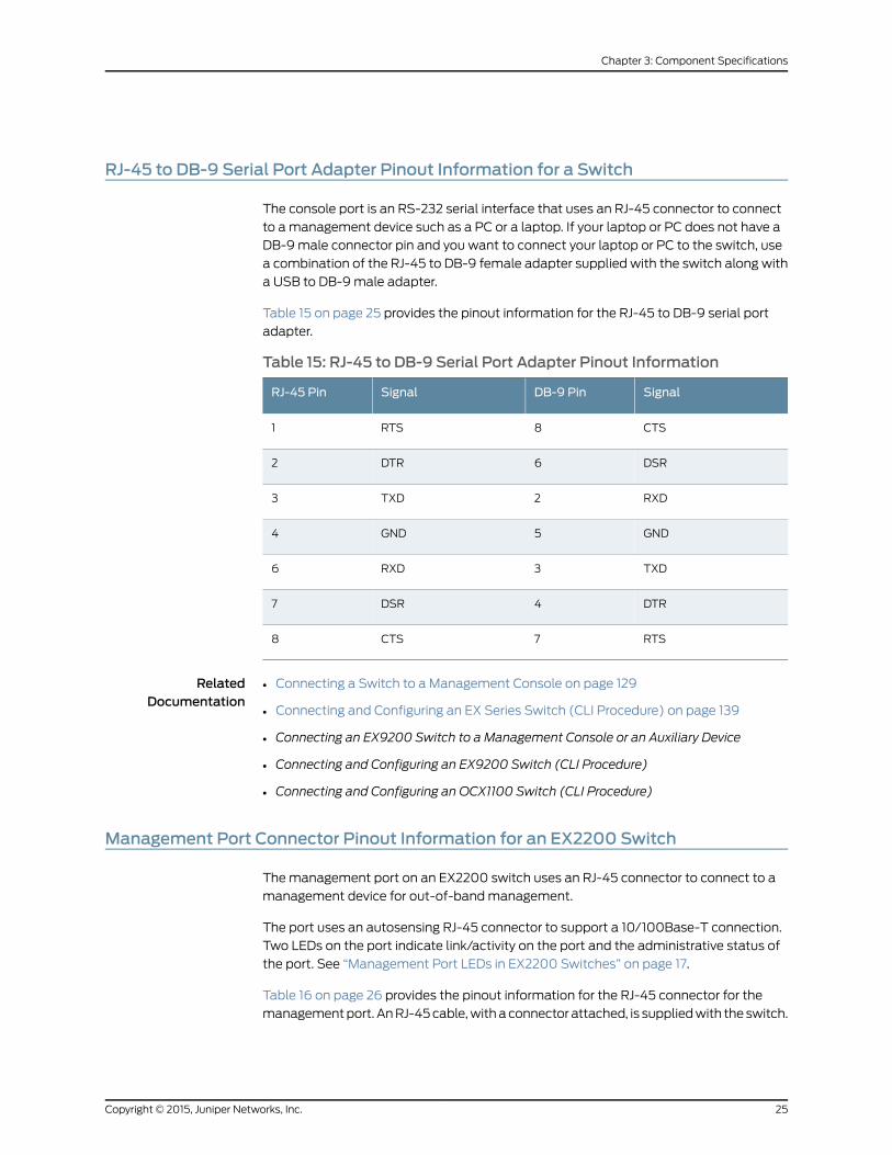
RJ-45 to DB-9 Serial Port Adapter Pinout Information for a Switch
The console port is an RS-232 serial interface that uses an RJ-45 connector to connect
to amanagement device such as a PC or a laptop. If your laptop or PC does not have a
DB-9male connector pin and you want to connect your laptop or PC to the switch, use
a combination of the RJ-45 to DB-9 female adapter supplied with the switch along with
a USB to DB-9male adapter.
Table 15 on page 25 provides the pinout information for the RJ-45 to DB-9 serial port
adapter.
Table 15: RJ-45 to DB-9 Serial Port Adapter Pinout Information
SignalDB-9 PinSignalRJ-45 Pin
CTS8RTS1
DSR6DTR2
RXD2TXD3
GND5GND4
TXD3RXD6
DTR4DSR7
RTS7CTS8
RelatedDocumentation
Connecting a Switch to a Management Console on page 129•
• Connecting and Configuring an EX Series Switch (CLI Procedure) on page 139
• Connecting an EX9200 Switch to a Management Console or an Auxiliary Device
• Connecting and Configuring an EX9200 Switch (CLI Procedure)
• Connecting and Configuring an OCX1100 Switch (CLI Procedure)
Management Port Connector Pinout Information for an EX2200 Switch
Themanagement port on an EX2200 switch uses an RJ-45 connector to connect to a
management device for out-of-bandmanagement.
The port uses an autosensing RJ-45 connector to support a 10/100Base-T connection.
Two LEDs on the port indicate link/activity on the port and the administrative status of
the port. See “Management Port LEDs in EX2200 Switches” on page 17.
Table 16 on page 26 provides the pinout information for the RJ-45 connector for the
managementport. AnRJ-45cable,withaconnector attached, is suppliedwith the switch.
25Copyright © 2015, Juniper Networks, Inc.
Chapter 3: Component Specifications
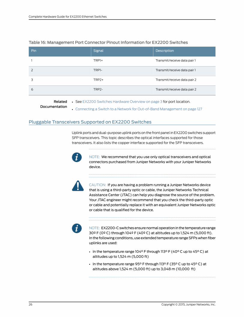
Table 16: Management Port Connector Pinout Information for EX2200 Switches
DescriptionSignalPin
Transmit/receive data pair 1TRP1+1
Transmit/receive data pair 1TRP1-2
Transmit/receive data pair 2TRP2+3
Transmit/receive data pair 2TRP2-6
RelatedDocumentation
See EX2200 Switches Hardware Overview on page 3 for port location.•
• Connecting a Switch to a Network for Out-of-Band Management on page 127
Pluggable Transceivers Supported on EX2200 Switches
Uplinkportsanddual-purposeuplinkportson the frontpanel inEX2200switchessupport
SFP transceivers. This topic describes the optical interfaces supported for those
transceivers. It also lists the copper interface supported for the SFP transceivers.
NOTE: We recommend that you use only optical transceivers and opticalconnectors purchased from Juniper Networks with your Juniper Networksdevice.
CAUTION: If you are having a problem running a Juniper Networks devicethat is using a third-party optic or cable, the Juniper Networks TechnicalAssistance Center (JTAC) can help you diagnose the source of the problem.Your JTAC engineer might recommend that you check the third-party opticor cable and potentially replace it with an equivalent Juniper Networks opticor cable that is qualified for the device.
NOTE: EX2200-Cswitchesensurenormaloperation in thetemperature range30º F (0º C) through 104º F (40º C) at altitudes up to 1,524m (5,000 ft).In the followingconditions, useextended temperature rangeSFPswhen fiberuplinks are used:
• In the temperature range 104° F through 113° F (40° C up to 45° C) ataltitudes up to 1,524m (5,000 ft)
• In the temperature range 95° F through 113° F (35° C up to 45° C) ataltitudes above 1,524m (5,000 ft) up to 3,048m (10,000 ft)
Copyright © 2015, Juniper Networks, Inc.26
Complete Hardware Guide for EX2200 Ethernet Switches
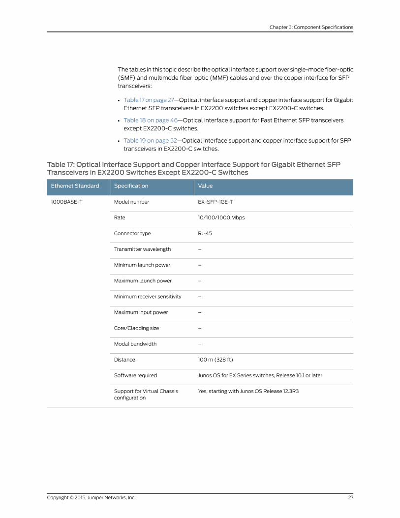
The tables in this topicdescribe theoptical interface support over single-mode fiber-optic
(SMF) andmultimode fiber-optic (MMF) cables and over the copper interface for SFP
transceivers:
• Table 17onpage27—Optical interface support andcopper interface support forGigabit
Ethernet SFP transceivers in EX2200 switches except EX2200-C switches.
• Table 18 on page 46—Optical interface support for Fast Ethernet SFP transceivers
except EX2200-C switches.
• Table 19 on page 52—Optical interface support and copper interface support for SFP
transceivers in EX2200-C switches.
Table 17: Optical interface Support and Copper Interface Support for Gigabit Ethernet SFPTransceivers in EX2200 Switches Except EX2200-C Switches
ValueSpecificationEthernet Standard
EX-SFP-1GE-TModel number1000BASE-T
10/100/1000MbpsRate
RJ-45Connector type
–Transmitter wavelength
–Minimum launch power
–Maximum launch power
–Minimum receiver sensitivity
–Maximum input power
–Core/Cladding size
–Modal bandwidth
100m (328 ft)Distance
Junos OS for EX Series switches, Release 10.1 or laterSoftware required
Yes, starting with Junos OS Release 12.3R3Support for Virtual Chassisconfiguration
27Copyright © 2015, Juniper Networks, Inc.
Chapter 3: Component Specifications
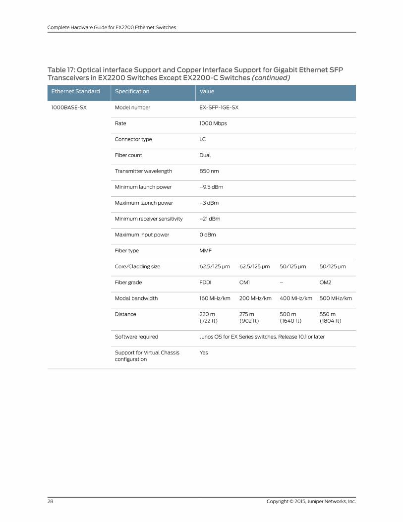
Table 17: Optical interface Support and Copper Interface Support for Gigabit Ethernet SFPTransceivers in EX2200 Switches Except EX2200-C Switches (continued)
ValueSpecificationEthernet Standard
EX-SFP-1GE-SXModel number1000BASE-SX
1000MbpsRate
LCConnector type
DualFiber count
850 nmTransmitter wavelength
–9.5 dBmMinimum launch power
–3 dBmMaximum launch power
–21 dBmMinimum receiver sensitivity
0 dBmMaximum input power
MMFFiber type
50/125 µm50/125 µm62.5/125 µm62.5/125 µmCore/Cladding size
OM2–OM1FDDIFiber grade
500MHz/km400MHz/km200MHz/km160MHz/kmModal bandwidth
550m(1804 ft)
500m(1640 ft)
275m(902 ft)
220m(722 ft)
Distance
Junos OS for EX Series switches, Release 10.1 or laterSoftware required
YesSupport for Virtual Chassisconfiguration
Copyright © 2015, Juniper Networks, Inc.28
Complete Hardware Guide for EX2200 Ethernet Switches
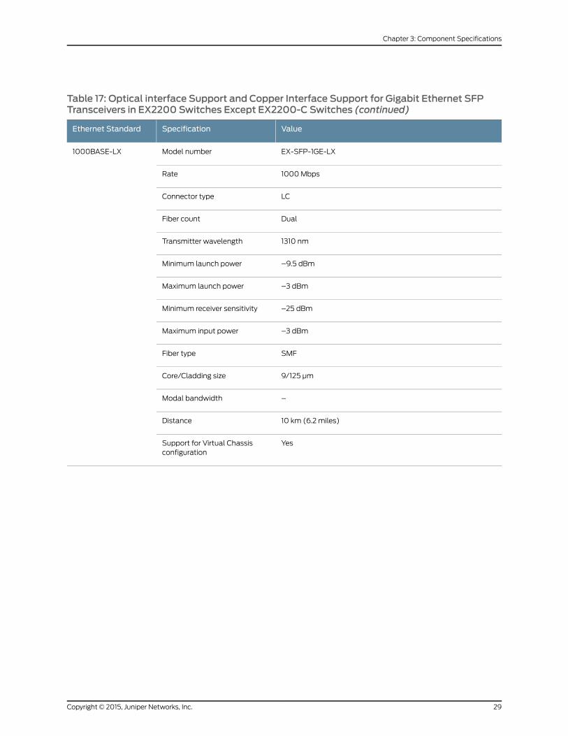
Table 17: Optical interface Support and Copper Interface Support for Gigabit Ethernet SFPTransceivers in EX2200 Switches Except EX2200-C Switches (continued)
ValueSpecificationEthernet Standard
EX-SFP-1GE-LXModel number1000BASE-LX
1000MbpsRate
LCConnector type
DualFiber count
1310 nmTransmitter wavelength
–9.5 dBmMinimum launch power
–3 dBmMaximum launch power
–25 dBmMinimum receiver sensitivity
–3 dBmMaximum input power
SMFFiber type
9/125 µmCore/Cladding size
–Modal bandwidth
10 km (6.2 miles)Distance
YesSupport for Virtual Chassisconfiguration
29Copyright © 2015, Juniper Networks, Inc.
Chapter 3: Component Specifications

Table 17: Optical interface Support and Copper Interface Support for Gigabit Ethernet SFPTransceivers in EX2200 Switches Except EX2200-C Switches (continued)
ValueSpecificationEthernet Standard
EX-SFP-GE10KT13R14Model number1000BASE-BX-U
1000MbpsRate
LCConnector type
SingleFiber count
1310 nmTransmitter wavelength
1490 nmReceiver wavelength
–9 dBmMinimum launch power
–3 dBmMaximum launch power
–30 dBmMinimum receiver sensitivity
–3 dBmMaximum input power
SMFFiber type
9/125 µmCore/Cladding size
–Modal bandwidth
10 km (6.2 miles)Distance
Junos OS for EX Series switches, Release 11.2 or laterSoftware required
YesSupport for Virtual Chassisconfiguration
Copyright © 2015, Juniper Networks, Inc.30
Complete Hardware Guide for EX2200 Ethernet Switches
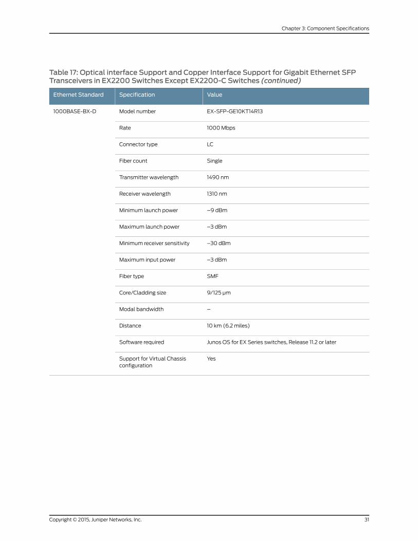
Table 17: Optical interface Support and Copper Interface Support for Gigabit Ethernet SFPTransceivers in EX2200 Switches Except EX2200-C Switches (continued)
ValueSpecificationEthernet Standard
EX-SFP-GE10KT14R13Model number1000BASE-BX-D
1000MbpsRate
LCConnector type
SingleFiber count
1490 nmTransmitter wavelength
1310 nmReceiver wavelength
–9 dBmMinimum launch power
–3 dBmMaximum launch power
–30 dBmMinimum receiver sensitivity
–3 dBmMaximum input power
SMFFiber type
9/125 µmCore/Cladding size
–Modal bandwidth
10 km (6.2 miles)Distance
Junos OS for EX Series switches, Release 11.2 or laterSoftware required
YesSupport for Virtual Chassisconfiguration
31Copyright © 2015, Juniper Networks, Inc.
Chapter 3: Component Specifications
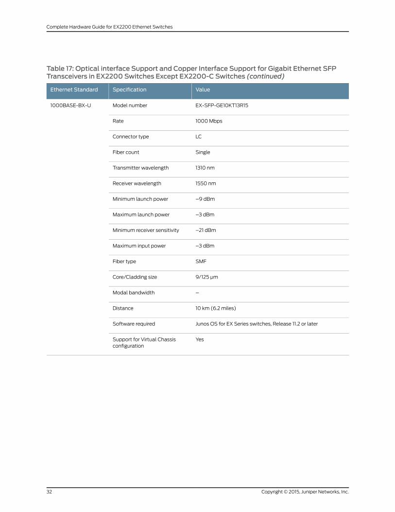
Table 17: Optical interface Support and Copper Interface Support for Gigabit Ethernet SFPTransceivers in EX2200 Switches Except EX2200-C Switches (continued)
ValueSpecificationEthernet Standard
EX-SFP-GE10KT13R15Model number1000BASE-BX-U
1000MbpsRate
LCConnector type
SingleFiber count
1310 nmTransmitter wavelength
1550 nmReceiver wavelength
–9 dBmMinimum launch power
–3 dBmMaximum launch power
–21 dBmMinimum receiver sensitivity
–3 dBmMaximum input power
SMFFiber type
9/125 µmCore/Cladding size
–Modal bandwidth
10 km (6.2 miles)Distance
Junos OS for EX Series switches, Release 11.2 or laterSoftware required
YesSupport for Virtual Chassisconfiguration
Copyright © 2015, Juniper Networks, Inc.32
Complete Hardware Guide for EX2200 Ethernet Switches

Table 17: Optical interface Support and Copper Interface Support for Gigabit Ethernet SFPTransceivers in EX2200 Switches Except EX2200-C Switches (continued)
ValueSpecificationEthernet Standard
EX-SFP-GE10KT15R13Model number1000BASE-BX-D
1000MbpsRate
LCConnector type
SingleFiber count
1550 nmTransmitter wavelength
1310 nmReceiver wavelength
–9 dBmMinimum launch power
–3 dBmMaximum launch power
–21 dBmMinimum receiver sensitivity
–3 dBmMaximum input power
SMFFiber type
9/125 µmCore/Cladding size
–Modal bandwidth
10 km (6.2 miles)Distance
Junos OS for EX Series switches, Release 11.2 or laterSoftware required
YesSupport for Virtual Chassisconfiguration
33Copyright © 2015, Juniper Networks, Inc.
Chapter 3: Component Specifications

Table 17: Optical interface Support and Copper Interface Support for Gigabit Ethernet SFPTransceivers in EX2200 Switches Except EX2200-C Switches (continued)
ValueSpecificationEthernet Standard
EX-SFP-GE40KT13R15Model number1000BASE-BX-U
1000MbpsRate
LCConnector type
SingleFiber count
1310 nmTransmitter wavelength
1550 nmReceiver wavelength
–6.5 dBmMinimum launch power
2 dBmMaximum launch power
–23 dBmMinimum receiver sensitivity
–3 dBmMaximum input power
SMFFiber type
9/125 µmCore/Cladding size
–Modal bandwidth
40 km (24.8 miles)Distance
Junos OS for EX Series switches, Release 11.2 or laterSoftware required
YesSupport for Virtual Chassisconfiguration
Copyright © 2015, Juniper Networks, Inc.34
Complete Hardware Guide for EX2200 Ethernet Switches

Table 17: Optical interface Support and Copper Interface Support for Gigabit Ethernet SFPTransceivers in EX2200 Switches Except EX2200-C Switches (continued)
ValueSpecificationEthernet Standard
EX-SFP-GE40KT15R13Model number1000BASE-BX-D
1000MbpsRate
LCConnector type
SingleFiber count
1550 nmTransmitter wavelength
1310 nmReceiver wavelength
–6.5 dBmMinimum launch power
2 dBmMaximum launch power
–23 dBmMinimum receiver sensitivity
–3 dBmMaximum input power
SMFFiber type
9/125 µmCore/Cladding size
–Modal bandwidth
40 km (24.8 miles)Distance
Junos OS for EX Series switches, Release 11.2 or laterSoftware required
YesSupport for Virtual Chassisconfiguration
35Copyright © 2015, Juniper Networks, Inc.
Chapter 3: Component Specifications
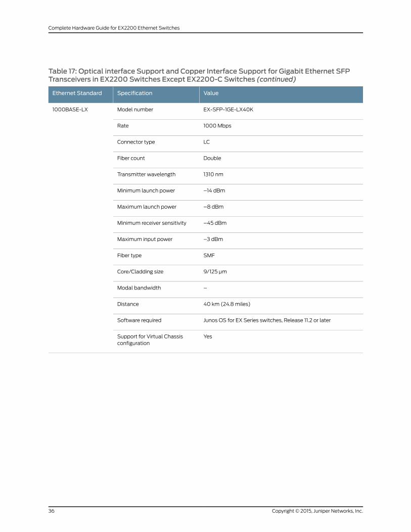
Table 17: Optical interface Support and Copper Interface Support for Gigabit Ethernet SFPTransceivers in EX2200 Switches Except EX2200-C Switches (continued)
ValueSpecificationEthernet Standard
EX-SFP-1GE-LX40KModel number1000BASE-LX
1000MbpsRate
LCConnector type
DoubleFiber count
1310 nmTransmitter wavelength
–14 dBmMinimum launch power
–8 dBmMaximum launch power
–45 dBmMinimum receiver sensitivity
–3 dBmMaximum input power
SMFFiber type
9/125 µmCore/Cladding size
–Modal bandwidth
40 km (24.8 miles)Distance
Junos OS for EX Series switches, Release 11.2 or laterSoftware required
YesSupport for Virtual Chassisconfiguration
Copyright © 2015, Juniper Networks, Inc.36
Complete Hardware Guide for EX2200 Ethernet Switches
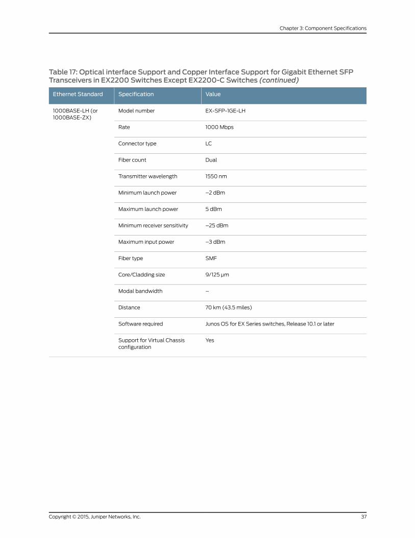
Table 17: Optical interface Support and Copper Interface Support for Gigabit Ethernet SFPTransceivers in EX2200 Switches Except EX2200-C Switches (continued)
ValueSpecificationEthernet Standard
EX-SFP-1GE-LHModel number1000BASE-LH (or1000BASE-ZX)
1000MbpsRate
LCConnector type
DualFiber count
1550 nmTransmitter wavelength
–2 dBmMinimum launch power
5 dBmMaximum launch power
–25 dBmMinimum receiver sensitivity
–3 dBmMaximum input power
SMFFiber type
9/125 µmCore/Cladding size
–Modal bandwidth
70 km (43.5 miles)Distance
Junos OS for EX Series switches, Release 10.1 or laterSoftware required
YesSupport for Virtual Chassisconfiguration
37Copyright © 2015, Juniper Networks, Inc.
Chapter 3: Component Specifications

Table 17: Optical interface Support and Copper Interface Support for Gigabit Ethernet SFPTransceivers in EX2200 Switches Except EX2200-C Switches (continued)
ValueSpecificationEthernet Standard
EX-SFP-GE80KCW1470Model number1000BASE-LX
1000MbpsRate
LCConnector type
SingleFiber count
1470 nmTransmitter wavelength
0 dBmMinimum launch power
5 dBmMaximum launch power
–32 dBmMinimum receiver sensitivity
–8 dBmMaximum input power
SMFFiber type
9/125 µmCore/Cladding size
–Modal bandwidth
80 km (49.7 miles)Distance
AvailableDOM support
Junos OS for EX Series switches, Release 12.1 or laterSoftware required
YesSupport for Virtual Chassisconfiguration
Copyright © 2015, Juniper Networks, Inc.38
Complete Hardware Guide for EX2200 Ethernet Switches

Table 17: Optical interface Support and Copper Interface Support for Gigabit Ethernet SFPTransceivers in EX2200 Switches Except EX2200-C Switches (continued)
ValueSpecificationEthernet Standard
EX-SFP-GE80KCW1490Model number1000BASE-LX
1000MbpsRate
LCConnector type
SingleFiber count
1490 nmTransmitter wavelength
0 dBmMinimum launch power
5 dBmMaximum launch power
–32 dBmMinimum receiver sensitivity
–8 dBmMaximum input power
SMFFiber type
9/125 µmCore/Cladding size
–Modal bandwidth
80 km (49.7 miles)Distance
AvailableDOM support
Junos OS for EX Series switches, Release 12.1 or laterSoftware required
YesSupport for Virtual Chassisconfiguration
39Copyright © 2015, Juniper Networks, Inc.
Chapter 3: Component Specifications
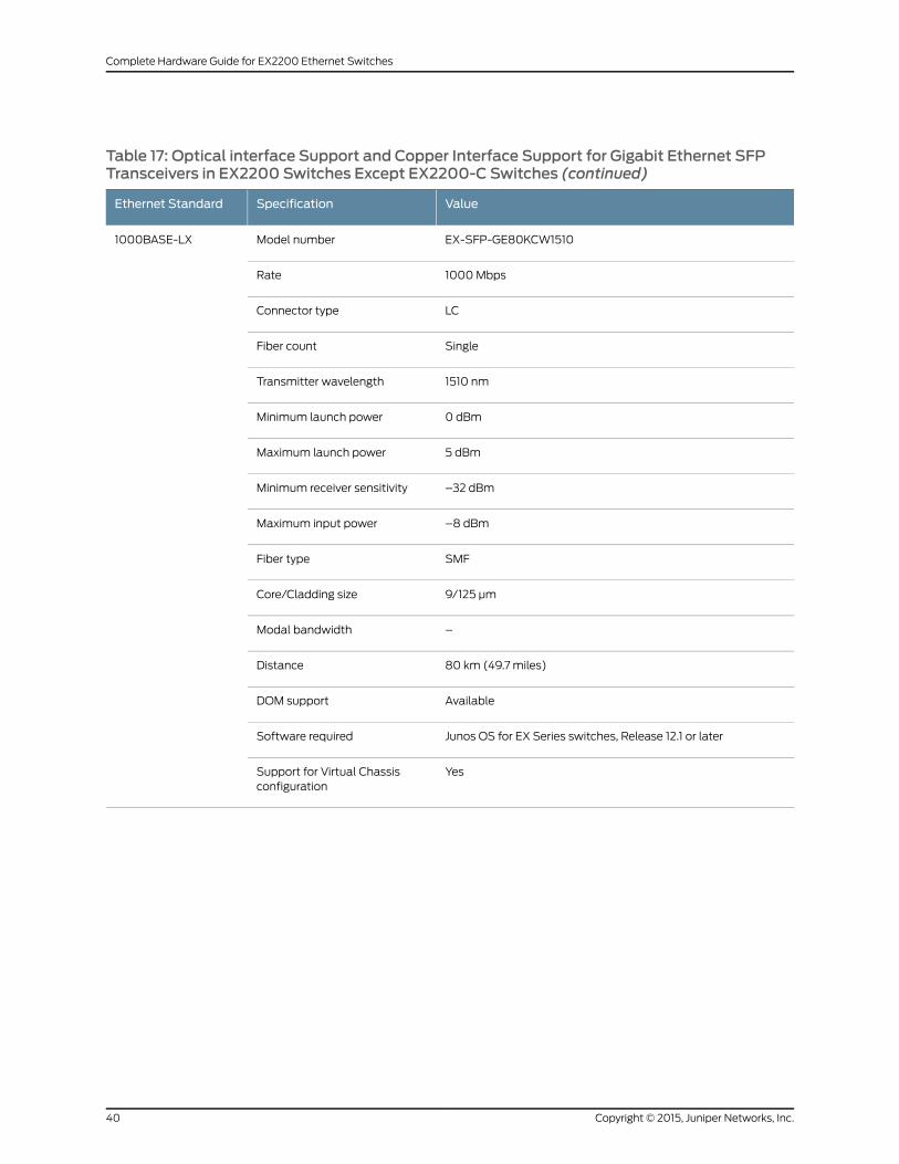
Table 17: Optical interface Support and Copper Interface Support for Gigabit Ethernet SFPTransceivers in EX2200 Switches Except EX2200-C Switches (continued)
ValueSpecificationEthernet Standard
EX-SFP-GE80KCW1510Model number1000BASE-LX
1000MbpsRate
LCConnector type
SingleFiber count
1510 nmTransmitter wavelength
0 dBmMinimum launch power
5 dBmMaximum launch power
–32 dBmMinimum receiver sensitivity
–8 dBmMaximum input power
SMFFiber type
9/125 µmCore/Cladding size
–Modal bandwidth
80 km (49.7 miles)Distance
AvailableDOM support
Junos OS for EX Series switches, Release 12.1 or laterSoftware required
YesSupport for Virtual Chassisconfiguration
Copyright © 2015, Juniper Networks, Inc.40
Complete Hardware Guide for EX2200 Ethernet Switches
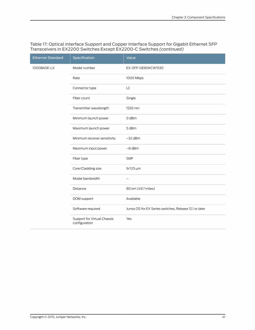
Table 17: Optical interface Support and Copper Interface Support for Gigabit Ethernet SFPTransceivers in EX2200 Switches Except EX2200-C Switches (continued)
ValueSpecificationEthernet Standard
EX-SFP-GE80KCW1530Model number1000BASE-LX
1000MbpsRate
LCConnector type
SingleFiber count
1530 nmTransmitter wavelength
0 dBmMinimum launch power
5 dBmMaximum launch power
–32 dBmMinimum receiver sensitivity
–8 dBmMaximum input power
SMFFiber type
9/125 µmCore/Cladding size
–Modal bandwidth
80 km (49.7 miles)Distance
AvailableDOM support
Junos OS for EX Series switches, Release 12.1 or laterSoftware required
YesSupport for Virtual Chassisconfiguration
41Copyright © 2015, Juniper Networks, Inc.
Chapter 3: Component Specifications

Table 17: Optical interface Support and Copper Interface Support for Gigabit Ethernet SFPTransceivers in EX2200 Switches Except EX2200-C Switches (continued)
ValueSpecificationEthernet Standard
EX-SFP-GE80KCW1550Model number1000BASE-LX
1000MbpsRate
LCConnector type
SingleFiber count
1550 nmTransmitter wavelength
0 dBmMinimum launch power
5 dBmMaximum launch power
–32 dBmMinimum receiver sensitivity
–8 dBmMaximum input power
SMFFiber type
9/125 µmCore/Cladding size
–Modal bandwidth
80 km (49.7 miles)Distance
AvailableDOM support
Junos OS for EX Series switches, Release 12.1 or laterSoftware required
YesSupport for Virtual Chassisconfiguration
Copyright © 2015, Juniper Networks, Inc.42
Complete Hardware Guide for EX2200 Ethernet Switches

Table 17: Optical interface Support and Copper Interface Support for Gigabit Ethernet SFPTransceivers in EX2200 Switches Except EX2200-C Switches (continued)
ValueSpecificationEthernet Standard
EX-SFP-GE80KCW1570Model number1000BASE-LX
1000MbpsRate
LCConnector type
SingleFiber count
1570 nmTransmitter wavelength
0 dBmMinimum launch power
5 dBmMaximum launch power
–32 dBmMinimum receiver sensitivity
–8 dBmMaximum input power
SMFFiber type
9/125 µmCore/Cladding size
–Modal bandwidth
80 km (49.7 miles)Distance
AvailableDOM support
Junos OS for EX Series switches, Release 12.1 or laterSoftware required
YesSupport for Virtual Chassisconfiguration
43Copyright © 2015, Juniper Networks, Inc.
Chapter 3: Component Specifications

Table 17: Optical interface Support and Copper Interface Support for Gigabit Ethernet SFPTransceivers in EX2200 Switches Except EX2200-C Switches (continued)
ValueSpecificationEthernet Standard
EX-SFP-GE80KCW1590Model number1000BASE-LX
1000MbpsRate
LCConnector type
SingleFiber count
1590 nmTransmitter wavelength
0 dBmMinimum launch power
5 dBmMaximum launch power
–32 dBmMinimum receiver sensitivity
–8 dBmMaximum input power
SMFFiber type
9/125 µmCore/Cladding size
–Modal bandwidth
80 km (49.7 miles)Distance
AvailableDOM support
Junos OS for EX Series switches, Release 12.1 or laterSoftware required
YesSupport for Virtual Chassisconfiguration
Copyright © 2015, Juniper Networks, Inc.44
Complete Hardware Guide for EX2200 Ethernet Switches

Table 17: Optical interface Support and Copper Interface Support for Gigabit Ethernet SFPTransceivers in EX2200 Switches Except EX2200-C Switches (continued)
ValueSpecificationEthernet Standard
EX-SFP-GE80KCW1610Model number1000BASE-LX
1000MbpsRate
LCConnector type
SingleFiber count
1610 nmTransmitter wavelength
0 dBmMinimum launch power
5 dBmMaximum launch power
–32 dBmMinimum receiver sensitivity
–8 dBmMaximum input power
SMFFiber type
9/125 µmCore/Cladding size
–Modal bandwidth
80 km (49.7 miles)Distance
AvailableDOM support
Junos OS for EX Series switches, Release 12.1 or laterSoftware required
YesSupport for Virtual Chassisconfiguration
45Copyright © 2015, Juniper Networks, Inc.
Chapter 3: Component Specifications
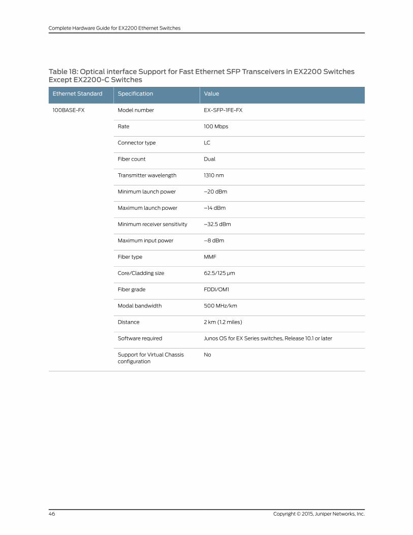
Table 18: Optical interface Support for Fast Ethernet SFP Transceivers in EX2200 SwitchesExcept EX2200-C Switches
ValueSpecificationEthernet Standard
EX-SFP-1FE-FXModel number100BASE-FX
100MbpsRate
LCConnector type
DualFiber count
1310 nmTransmitter wavelength
–20 dBmMinimum launch power
–14 dBmMaximum launch power
–32.5 dBmMinimum receiver sensitivity
–8 dBmMaximum input power
MMFFiber type
62.5/125 µmCore/Cladding size
FDDI/OM1Fiber grade
500MHz/kmModal bandwidth
2 km (1.2 miles)Distance
Junos OS for EX Series switches, Release 10.1 or laterSoftware required
NoSupport for Virtual Chassisconfiguration
Copyright © 2015, Juniper Networks, Inc.46
Complete Hardware Guide for EX2200 Ethernet Switches

Table 18: Optical interface Support for Fast Ethernet SFP Transceivers in EX2200 SwitchesExcept EX2200-C Switches (continued)
ValueSpecificationEthernet Standard
EX-SFP-1FE-LXModel number100BASE-LX
100MbpsRate
LCConnector type
DualFiber count
1310 nmTransmitter wavelength
–15 dBmMinimum launch power
–8 dBmMaximum launch power
–31.5 dBmMinimum receiver sensitivity
–8 dBmMaximum input power
SMFFiber type
9/125 µmCore/Cladding size
–Modal bandwidth
10 km (6.2 miles)Distance
Junos OS for EX Series switches, Release 11.2 or laterSoftware required
NoSupport for Virtual Chassisconfiguration
47Copyright © 2015, Juniper Networks, Inc.
Chapter 3: Component Specifications
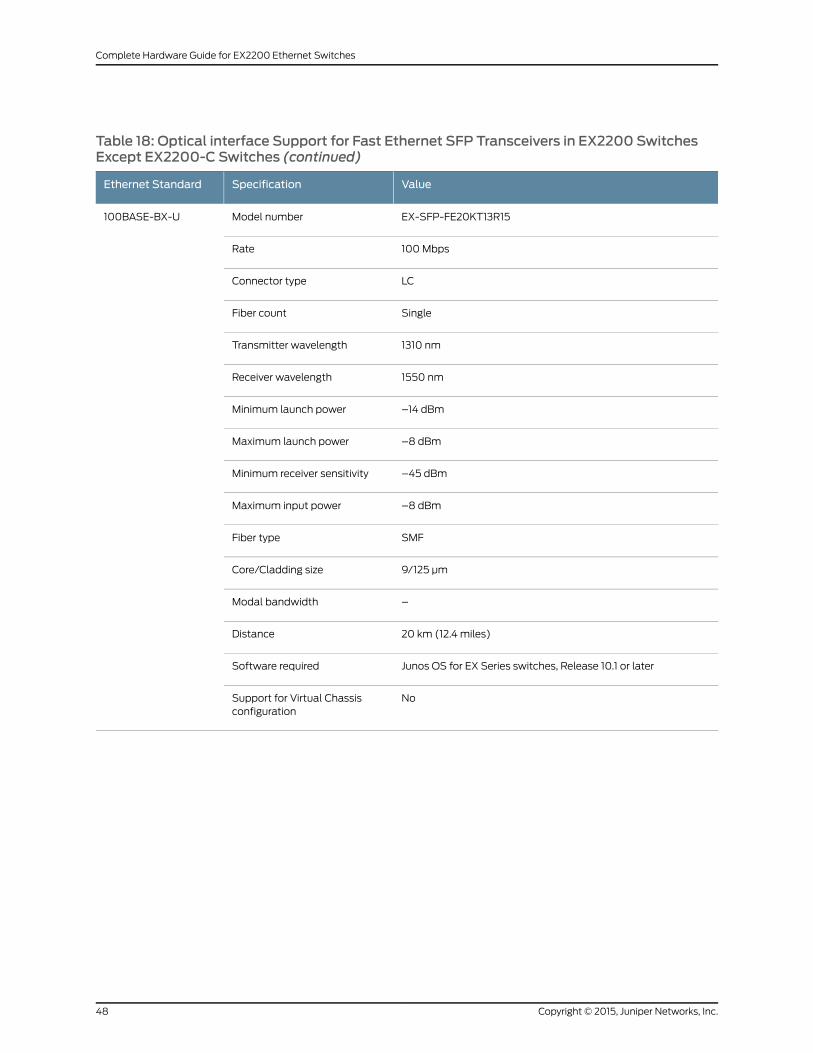
Table 18: Optical interface Support for Fast Ethernet SFP Transceivers in EX2200 SwitchesExcept EX2200-C Switches (continued)
ValueSpecificationEthernet Standard
EX-SFP-FE20KT13R15Model number100BASE-BX-U
100MbpsRate
LCConnector type
SingleFiber count
1310 nmTransmitter wavelength
1550 nmReceiver wavelength
–14 dBmMinimum launch power
–8 dBmMaximum launch power
–45 dBmMinimum receiver sensitivity
–8 dBmMaximum input power
SMFFiber type
9/125 µmCore/Cladding size
–Modal bandwidth
20 km (12.4 miles)Distance
Junos OS for EX Series switches, Release 10.1 or laterSoftware required
NoSupport for Virtual Chassisconfiguration
Copyright © 2015, Juniper Networks, Inc.48
Complete Hardware Guide for EX2200 Ethernet Switches
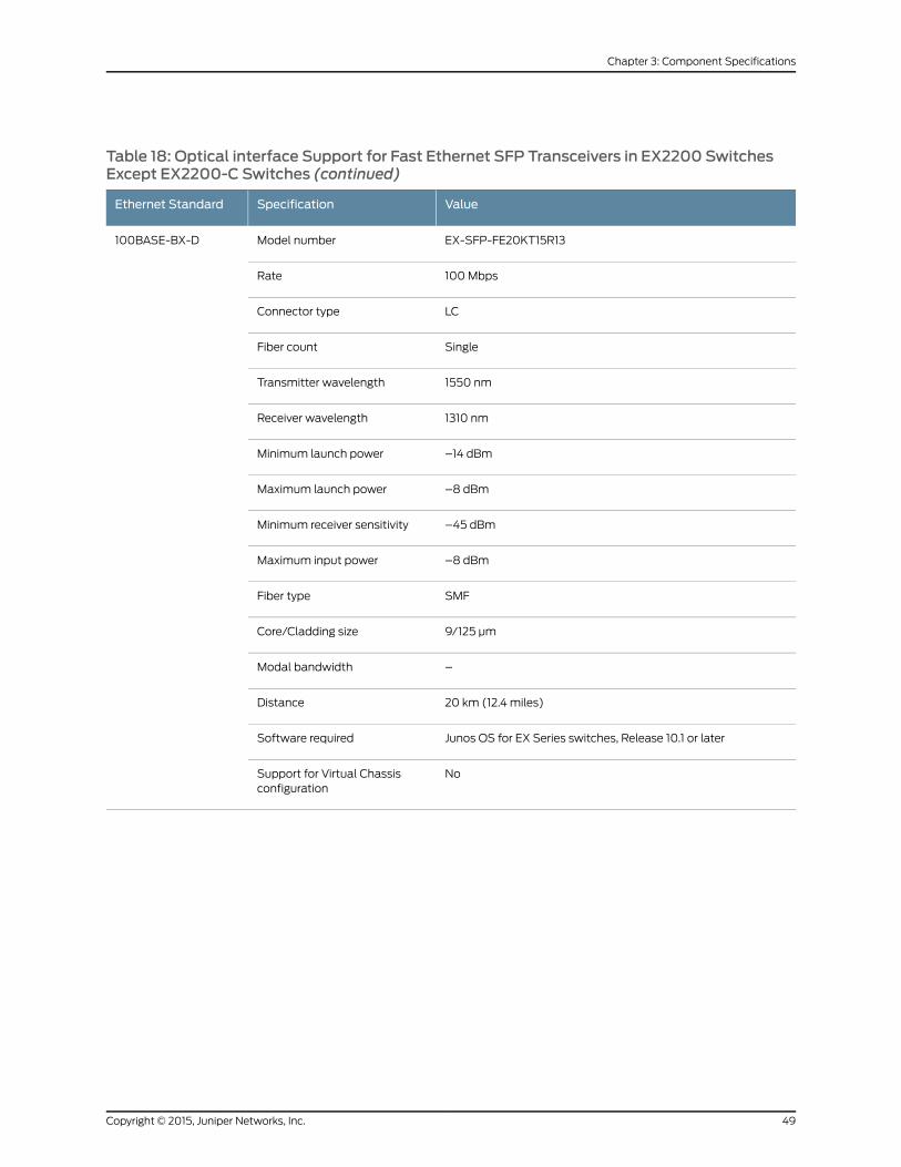
Table 18: Optical interface Support for Fast Ethernet SFP Transceivers in EX2200 SwitchesExcept EX2200-C Switches (continued)
ValueSpecificationEthernet Standard
EX-SFP-FE20KT15R13Model number100BASE-BX-D
100MbpsRate
LCConnector type
SingleFiber count
1550 nmTransmitter wavelength
1310 nmReceiver wavelength
–14 dBmMinimum launch power
–8 dBmMaximum launch power
–45 dBmMinimum receiver sensitivity
–8 dBmMaximum input power
SMFFiber type
9/125 µmCore/Cladding size
–Modal bandwidth
20 km (12.4 miles)Distance
Junos OS for EX Series switches, Release 10.1 or laterSoftware required
NoSupport for Virtual Chassisconfiguration
49Copyright © 2015, Juniper Networks, Inc.
Chapter 3: Component Specifications

Table 18: Optical interface Support for Fast Ethernet SFP Transceivers in EX2200 SwitchesExcept EX2200-C Switches (continued)
ValueSpecificationEthernet Standard
EX-SFP-1FE-LX40KModel number100BASE-LX40K
100MbpsRate
LCConnector type
DualFiber count
1310 nmTransmitter wavelength
–5 dBmMinimum launch power
0 dBmMaximum launch power
–32 dBmMinimum receiver sensitivity
–8 dBmMaximum input power
SMFFiber type
9/125 µmCore/Cladding size
–Modal bandwidth
40 km (24.8 miles)Distance
Junos OS for EX Series switches, Release 11.2 or laterSoftware required
NoSupport for Virtual Chassisconfiguration
Copyright © 2015, Juniper Networks, Inc.50
Complete Hardware Guide for EX2200 Ethernet Switches
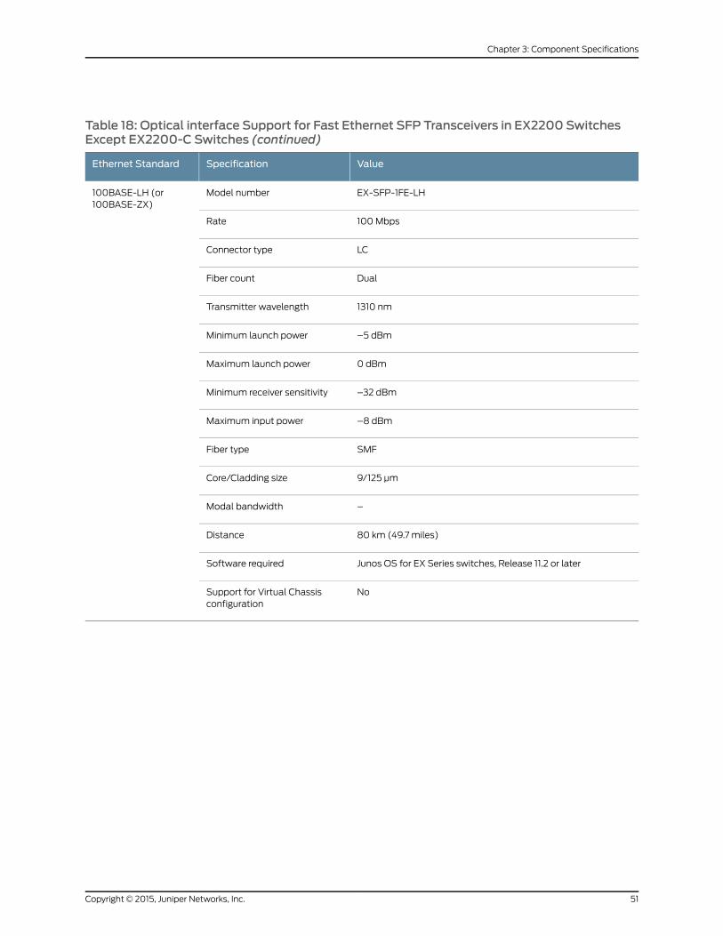
Table 18: Optical interface Support for Fast Ethernet SFP Transceivers in EX2200 SwitchesExcept EX2200-C Switches (continued)
ValueSpecificationEthernet Standard
EX-SFP-1FE-LHModel number100BASE-LH (or100BASE-ZX)
100MbpsRate
LCConnector type
DualFiber count
1310 nmTransmitter wavelength
–5 dBmMinimum launch power
0 dBmMaximum launch power
–32 dBmMinimum receiver sensitivity
–8 dBmMaximum input power
SMFFiber type
9/125 µmCore/Cladding size
–Modal bandwidth
80 km (49.7 miles)Distance
Junos OS for EX Series switches, Release 11.2 or laterSoftware required
NoSupport for Virtual Chassisconfiguration
51Copyright © 2015, Juniper Networks, Inc.
Chapter 3: Component Specifications

Table 19: Optical interface Support and Copper Interface Support for SFP Transceivers inEX2200-C Switches
ValueSpecificationEthernet Standard
EX-SFP-1GE-SXModel number1000BASE-SX
1000MbpsRate
LCConnector type
DualFiber count
850 nmTransmitter wavelength
–9.5 dBmMinimum launch power
–3 dBmMaximum launch power
–21 dBmMinimum receiver sensitivity
0 dBmMaximum input power
MMFFiber type
50/125 µm50/125 µm62.5/125 µm62.5/125 µmCore/Cladding size
OM2–OM1FDDIFiber grade
500MHz/km400MHz/km200MHz/km160MHz/kmModal bandwidth
550m(1804 ft)
500m(1640 ft)
275m(902 ft)
220m(722 ft)
Distance
Junos OS for EX Series switches, Release 11.3 or laterSoftware required
YesSupport for Virtual Chassisconfiguration
Copyright © 2015, Juniper Networks, Inc.52
Complete Hardware Guide for EX2200 Ethernet Switches
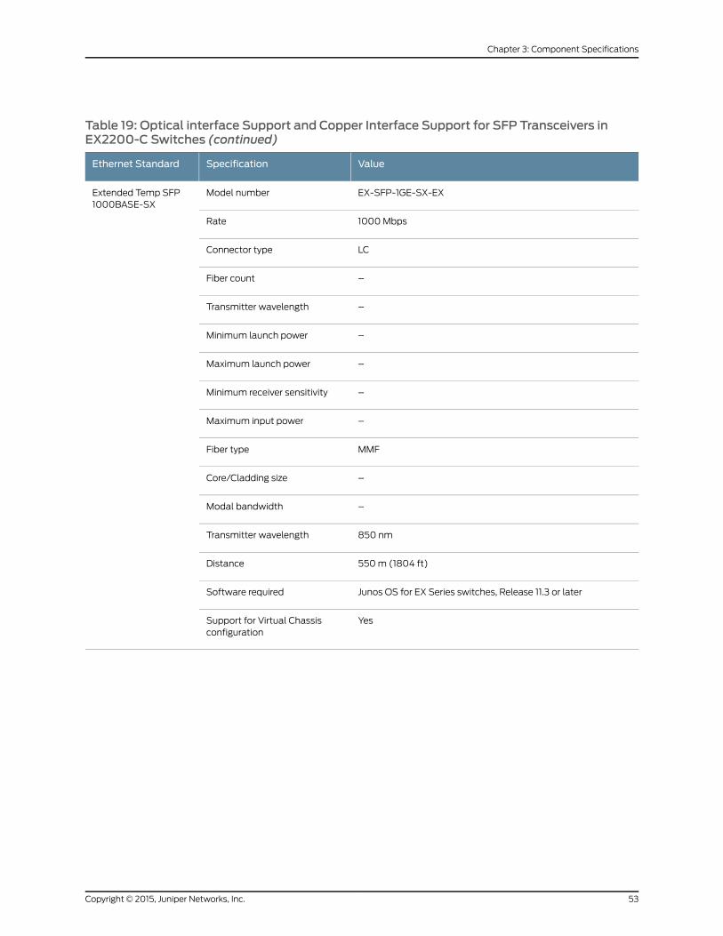
Table 19: Optical interface Support and Copper Interface Support for SFP Transceivers inEX2200-C Switches (continued)
ValueSpecificationEthernet Standard
EX-SFP-1GE-SX-EXModel numberExtended Temp SFP1000BASE-SX
1000MbpsRate
LCConnector type
–Fiber count
–Transmitter wavelength
–Minimum launch power
–Maximum launch power
–Minimum receiver sensitivity
–Maximum input power
MMFFiber type
–Core/Cladding size
–Modal bandwidth
850 nmTransmitter wavelength
550m (1804 ft)Distance
Junos OS for EX Series switches, Release 11.3 or laterSoftware required
YesSupport for Virtual Chassisconfiguration
53Copyright © 2015, Juniper Networks, Inc.
Chapter 3: Component Specifications
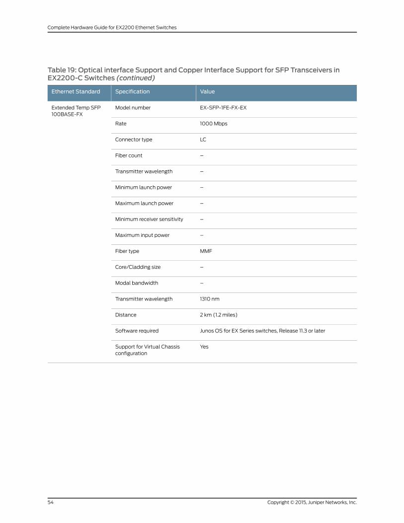
Table 19: Optical interface Support and Copper Interface Support for SFP Transceivers inEX2200-C Switches (continued)
ValueSpecificationEthernet Standard
EX-SFP-1FE-FX-EXModel numberExtended Temp SFP100BASE-FX
1000MbpsRate
LCConnector type
–Fiber count
–Transmitter wavelength
–Minimum launch power
–Maximum launch power
–Minimum receiver sensitivity
–Maximum input power
MMFFiber type
–Core/Cladding size
–Modal bandwidth
1310 nmTransmitter wavelength
2 km (1.2 miles)Distance
Junos OS for EX Series switches, Release 11.3 or laterSoftware required
YesSupport for Virtual Chassisconfiguration
Copyright © 2015, Juniper Networks, Inc.54
Complete Hardware Guide for EX2200 Ethernet Switches
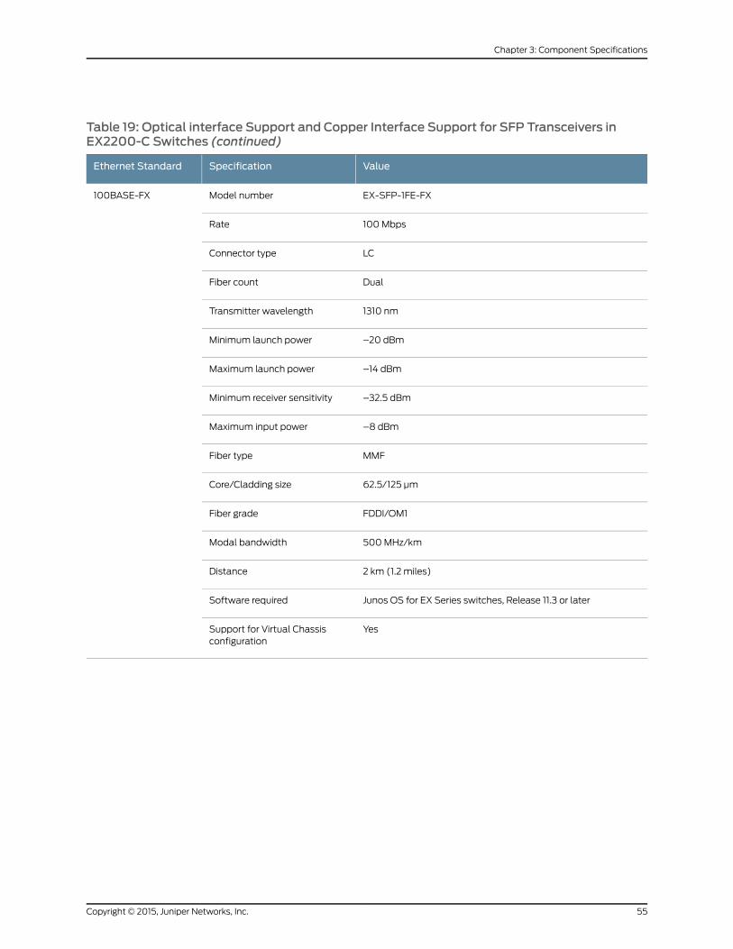
Table 19: Optical interface Support and Copper Interface Support for SFP Transceivers inEX2200-C Switches (continued)
ValueSpecificationEthernet Standard
EX-SFP-1FE-FXModel number100BASE-FX
100MbpsRate
LCConnector type
DualFiber count
1310 nmTransmitter wavelength
–20 dBmMinimum launch power
–14 dBmMaximum launch power
–32.5 dBmMinimum receiver sensitivity
–8 dBmMaximum input power
MMFFiber type
62.5/125 µmCore/Cladding size
FDDI/OM1Fiber grade
500MHz/kmModal bandwidth
2 km (1.2 miles)Distance
Junos OS for EX Series switches, Release 11.3 or laterSoftware required
YesSupport for Virtual Chassisconfiguration
55Copyright © 2015, Juniper Networks, Inc.
Chapter 3: Component Specifications

Table 19: Optical interface Support and Copper Interface Support for SFP Transceivers inEX2200-C Switches (continued)
ValueSpecificationEthernet Standard
EX-SFP-1GE-LXModel number1000BASE-LX
1000MbpsRate
LCConnector type
DualFiber count
1310 nmTransmitter wavelength
–9.5 dBmMinimum launch power
–3 dBmMaximum launch power
–25 dBmMinimum receiver sensitivity
–3 dBmMaximum input power
SMFFiber type
9/125 µmCore/Cladding size
–Modal bandwidth
10 km (6.2 miles)Distance
Junos OS for EX Series switches, Release 11.3 or laterSoftware required
YesSupport for Virtual Chassisconfiguration
Copyright © 2015, Juniper Networks, Inc.56
Complete Hardware Guide for EX2200 Ethernet Switches
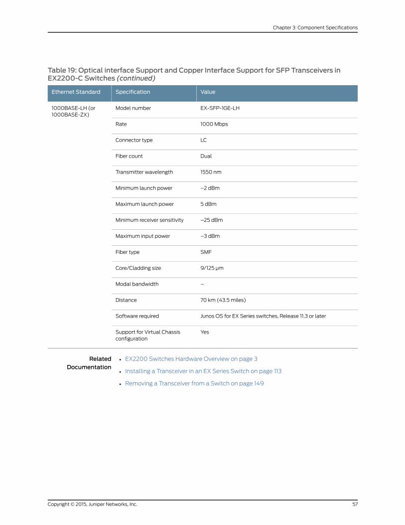
Table 19: Optical interface Support and Copper Interface Support for SFP Transceivers inEX2200-C Switches (continued)
ValueSpecificationEthernet Standard
EX-SFP-1GE-LHModel number1000BASE-LH (or1000BASE-ZX)
1000MbpsRate
LCConnector type
DualFiber count
1550 nmTransmitter wavelength
–2 dBmMinimum launch power
5 dBmMaximum launch power
–25 dBmMinimum receiver sensitivity
–3 dBmMaximum input power
SMFFiber type
9/125 µmCore/Cladding size
–Modal bandwidth
70 km (43.5 miles)Distance
Junos OS for EX Series switches, Release 11.3 or laterSoftware required
YesSupport for Virtual Chassisconfiguration
RelatedDocumentation
• EX2200 Switches Hardware Overview on page 3
• Installing a Transceiver in an EX Series Switch on page 113
• Removing a Transceiver from a Switch on page 149
57Copyright © 2015, Juniper Networks, Inc.
Chapter 3: Component Specifications

Copyright © 2015, Juniper Networks, Inc.58
Complete Hardware Guide for EX2200 Ethernet Switches

PART 2
Planning for Switch Installation
• Site Preparation on page 61
• Mounting and Clearance Requirements on page 71
• Cable Specifications on page 77
• Planning Power Requirements on page 79
59Copyright © 2015, Juniper Networks, Inc.

Copyright © 2015, Juniper Networks, Inc.60
Complete Hardware Guide for EX2200 Ethernet Switches
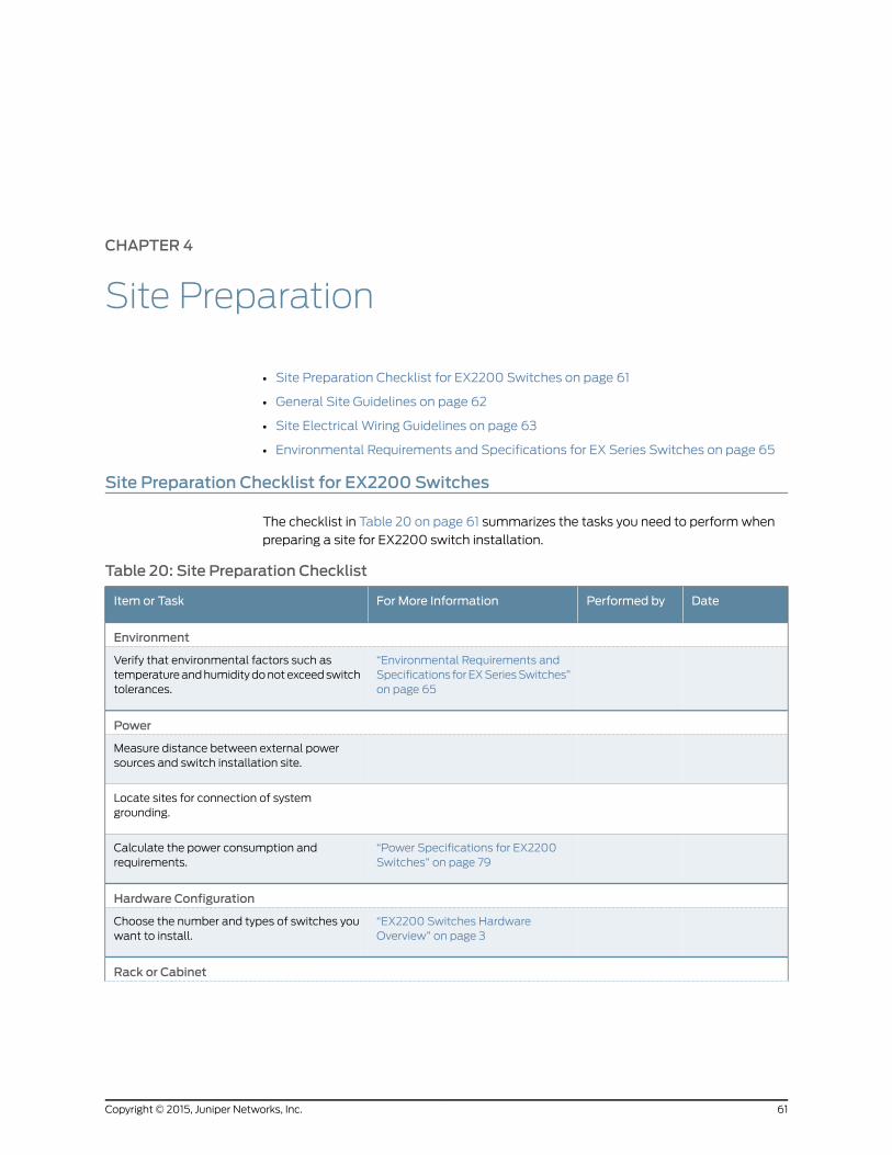
CHAPTER 4
Site Preparation
• Site Preparation Checklist for EX2200 Switches on page 61
• General Site Guidelines on page 62
• Site Electrical Wiring Guidelines on page 63
• Environmental Requirements and Specifications for EX Series Switches on page 65
Site Preparation Checklist for EX2200 Switches
The checklist in Table 20 on page 61 summarizes the tasks you need to performwhen
preparing a site for EX2200 switch installation.
Table 20: Site Preparation Checklist
DatePerformed byFor More InformationItem or Task
Environment
“Environmental Requirements andSpecifications forEXSeriesSwitches”on page 65
Verify that environmental factors such astemperatureandhumiditydonotexceedswitchtolerances.
Power
Measure distance between external powersources and switch installation site.
Locate sites for connection of systemgrounding.
“Power Specifications for EX2200Switches” on page 79
Calculate the power consumption andrequirements.
Hardware Configuration
“EX2200 Switches HardwareOverview” on page 3
Choose the number and types of switches youwant to install.
Rack or Cabinet
61Copyright © 2015, Juniper Networks, Inc.
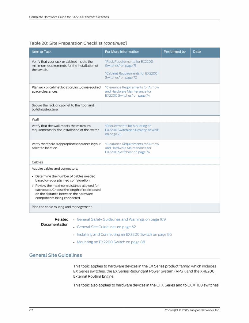
Table 20: Site Preparation Checklist (continued)
DatePerformed byFor More InformationItem or Task
“Rack Requirements for EX2200Switches” on page 71
“Cabinet Requirements for EX2200Switches” on page 72
Verify that your rack or cabinet meets theminimum requirements for the installation ofthe switch.
“Clearance Requirements for Airflowand Hardware Maintenance forEX2200 Switches” on page 74
Plan rackor cabinet location, including requiredspace clearances.
Secure the rack or cabinet to the floor andbuilding structure.
Wall
“Requirements for Mounting anEX2200SwitchonaDesktoporWall”on page 73
Verify that the wall meets the minimumrequirements for the installation of the switch.
“Clearance Requirements for Airflowand Hardware Maintenance forEX2200 Switches” on page 74
Verify that there is appropriate clearance in yourselected location.
Cables
Acquire cables and connectors:
• Determine the number of cables neededbased on your planned configuration.
• Review themaximum distance allowed foreachcable.Choose the lengthof cablebasedon the distance between the hardwarecomponents being connected.
Plan the cable routing andmanagement.
RelatedDocumentation
General Safety Guidelines andWarnings on page 169•
• General Site Guidelines on page 62
• Installing and Connecting an EX2200 Switch on page 85
• Mounting an EX2200 Switch on page 88
General Site Guidelines
This topic applies to hardware devices in the EX Series product family, which includes
EX Series switches, the EX Series Redundant Power System (RPS), and the XRE200
External Routing Engine.
This topic also applies to hardware devices in the QFX Series and to OCX1100 switches.
Copyright © 2015, Juniper Networks, Inc.62
Complete Hardware Guide for EX2200 Ethernet Switches

Efficient device operation requires proper site planning andmaintenance and proper
layout of the equipment, rack or cabinet (if used), and wiring closet.
To plan and create an acceptable operating environment for your device and prevent
environmentally caused equipment failures:
• Keep the area around the chassis free from dust and conductive material, such as
metal flakes.
• Followprescribedairflowguidelines toensure that thecoolingsystemfunctionsproperly
and that exhaust from other equipment does not blow into the intake vents of the
device.
• Follow the prescribed electrostatic discharge (ESD) prevention procedures to prevent
damaging the equipment. Static discharge can cause components to fail completely
or intermittently over time.
• Install the device in a secure area, so that only authorized personnel can access the
device.
RelatedDocumentation
Prevention of Electrostatic Discharge Damage on page 198•
• Environmental Requirements and Specifications for EX Series Switches on page 65
• Environmental Requirements and Specifications for OCX1100 Switches
• Environmental Requirements and Specifications for a QFX3100 Director Device
• Environmental Requirements and Specifications for a QFX3008-I Interconnect Device
• Environmental Requirements and Specifications for a QFX3500 Device
• Environmental Requirements and Specifications for QFX3600 and QFX3600-I Devices
• Environmental Requirements and Specifications for a QFX5100 Device
Site ElectricalWiring Guidelines
This topic applies to hardware devices in the EX Series product family, which includes
EX Series switches, the EX Series Redundant Power System (RPS), and the XRE200
External Routing Engine.
This topic also applies to hardware devices in the QFX Series and to OCX1100 switches.
Table 21 on page64describes the factors youmust considerwhile planning the electrical
wiring at your site.
WARNING: It is particularly important to provide a properly grounded andshielded environment and to use electrical surge-suppression devices.
63Copyright © 2015, Juniper Networks, Inc.
Chapter 4: Site Preparation
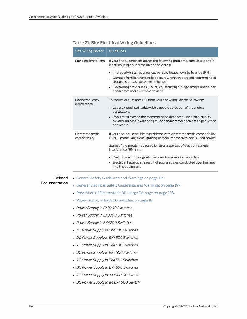
Table 21: Site ElectricalWiring Guidelines
GuidelinesSiteWiring Factor
If your site experiences any of the following problems, consult experts inelectrical surge suppression and shielding:
• Improperly installed wires cause radio frequency interference (RFI).
• Damage from lightning strikesoccurswhenwiresexceed recommendeddistances or pass between buildings.
• Electromagneticpulses (EMPs)causedby lightningdamageunshieldedconductors and electronic devices.
Signaling limitations
To reduce or eliminate RFI from your site wiring, do the following:
• Use a twisted-pair cable with a good distribution of groundingconductors.
• If you must exceed the recommended distances, use a high-qualitytwisted-pair cablewithonegroundconductor for eachdata signalwhenapplicable.
Radio frequencyinterference
If your site is susceptible to problems with electromagnetic compatibility(EMC), particularly from lightningor radio transmitters, seek expert advice.
Some of the problems caused by strong sources of electromagneticinterference (EMI) are:
• Destruction of the signal drivers and receivers in the switch
• Electrical hazards as a result of power surges conducted over the linesinto the equipment
Electromagneticcompatibility
RelatedDocumentation
General Safety Guidelines andWarnings on page 169•
• General Electrical Safety Guidelines andWarnings on page 197
• Prevention of Electrostatic Discharge Damage on page 198
• Power Supply in EX2200 Switches on page 18
• Power Supply in EX3200 Switches
• Power Supply in EX3300 Switches
• Power Supply in EX4200 Switches
• AC Power Supply in EX4300 Switches
• DC Power Supply in EX4300 Switches
• AC Power Supply in EX4500 Switches
• DC Power Supply in EX4500 Switches
• AC Power Supply in EX4550 Switches
• DC Power Supply in EX4550 Switches
• AC Power Supply in an EX4600 Switch
• DC Power Supply in an EX4600 Switch
Copyright © 2015, Juniper Networks, Inc.64
Complete Hardware Guide for EX2200 Ethernet Switches

• AC Power Supplies in an EX6200 Switch
• DC Power Supply in an EX6200 Switch
• AC Power Supply in an EX8200 Switch
• DC Power Supply in an EX8200 Switch
• AC Power Supply in an EX9204 Switch
• DC Power Supply in an EX9204 Switch
• AC Power Supply in an EX9208 Switch
• DC Power Supply in an EX9208 Switch
• AC Power Supply in an EX9214 Switch
• DC Power Supply in an EX9214 Switch
• Power Supply in an EX Series Redundant Power System
• AC Power Supply in OCX1100 Switches
• DC Power Supply in OCX1100 Switches
• AC Power Supply in a QFX3100 Director Device
• AC Power Supply in a QFX3008-I Interconnect Device
• Wiring Tray in a QFX3008-I Interconnect Device
• AC Power Supply for a QFX3500, QFX3600, or QFX3600-I Device
• DC Power Supply for a QFX3500, QFX3600, or QFX3600-I Device
• AC Power Supply for a QFX5100 Device
• DC Power Supply in a QFX5100 Device
Environmental Requirements and Specifications for EX Series Switches
The switch must be installed in a rack or cabinet housed in a dry, clean, well-ventilated,
and temperature-controlled environment.
Ensure that these environmental guidelines are followed:
• The site must be as dust-free as possible, because dust can clog air intake vents and
filters, reducing the efficiency of the switch cooling system.
• Maintain ambient airflow for normal switch operation. If the airflow is blocked or
restricted, or if the intake air is too warm, the switch might overheat, leading to the
switch temperature monitor shutting down the switch to protect the hardware
components.
Table 22 on page 66 provides the required environmental conditions for normal switch
operation.
65Copyright © 2015, Juniper Networks, Inc.
Chapter 4: Site Preparation
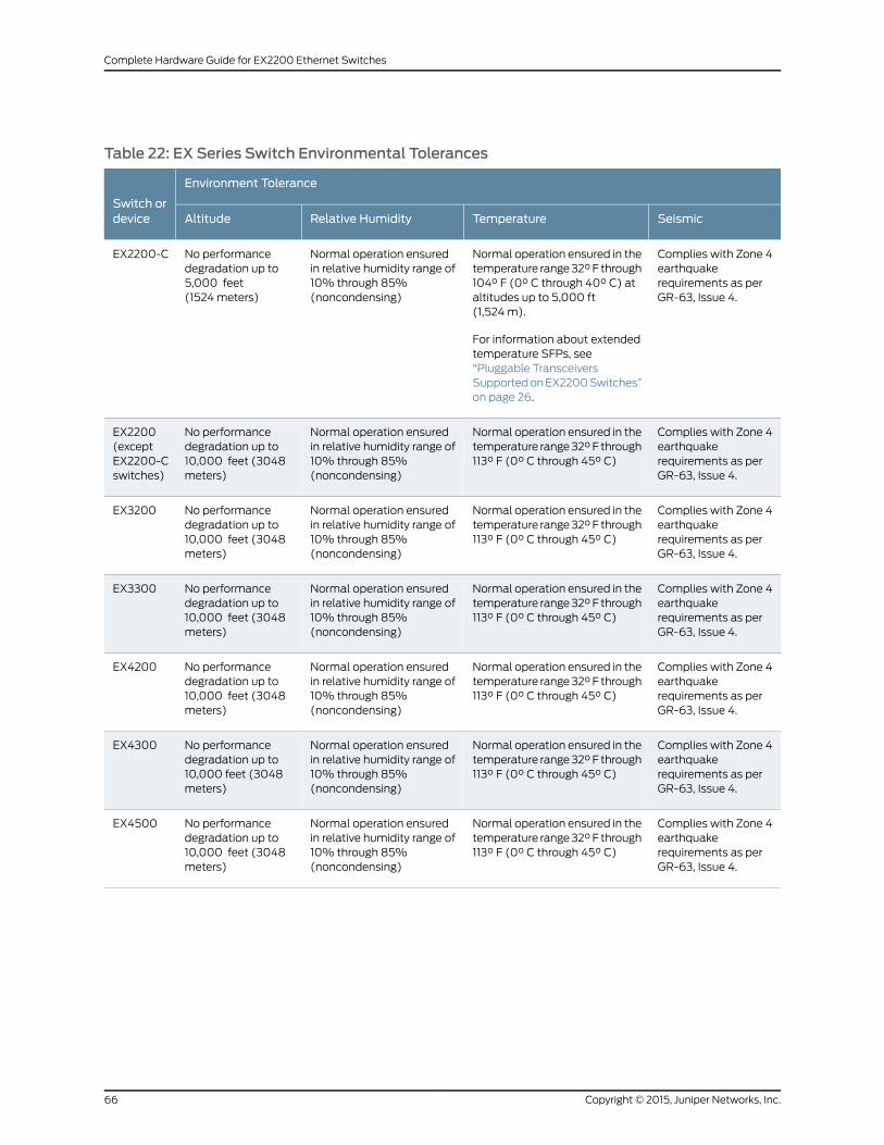
Table 22: EX Series Switch Environmental Tolerances
Environment Tolerance
Switch ordevice SeismicTemperatureRelative HumidityAltitude
Complies with Zone 4earthquakerequirements as perGR-63, Issue 4.
Normal operation ensured in thetemperature range32°F through104° F (0° C through 40° C) ataltitudes up to 5,000 ft(1,524m).
For information about extendedtemperature SFPs, see“Pluggable TransceiversSupportedonEX2200Switches”on page 26.
Normal operation ensuredin relative humidity range of10% through 85%(noncondensing)
No performancedegradation up to5,000 feet(1524meters)
EX2200-C
Complies with Zone 4earthquakerequirements as perGR-63, Issue 4.
Normal operation ensured in thetemperature range32°F through113° F (0° C through 45° C)
Normal operation ensuredin relative humidity range of10% through 85%(noncondensing)
No performancedegradation up to10,000 feet (3048meters)
EX2200(exceptEX2200-Cswitches)
Complies with Zone 4earthquakerequirements as perGR-63, Issue 4.
Normal operation ensured in thetemperature range32°F through113° F (0° C through 45° C)
Normal operation ensuredin relative humidity range of10% through 85%(noncondensing)
No performancedegradation up to10,000 feet (3048meters)
EX3200
Complies with Zone 4earthquakerequirements as perGR-63, Issue 4.
Normal operation ensured in thetemperature range32°F through113° F (0° C through 45° C)
Normal operation ensuredin relative humidity range of10% through 85%(noncondensing)
No performancedegradation up to10,000 feet (3048meters)
EX3300
Complies with Zone 4earthquakerequirements as perGR-63, Issue 4.
Normal operation ensured in thetemperature range32°F through113° F (0° C through 45° C)
Normal operation ensuredin relative humidity range of10% through 85%(noncondensing)
No performancedegradation up to10,000 feet (3048meters)
EX4200
Complies with Zone 4earthquakerequirements as perGR-63, Issue 4.
Normal operation ensured in thetemperature range32°F through113° F (0° C through 45° C)
Normal operation ensuredin relative humidity range of10% through 85%(noncondensing)
No performancedegradation up to10,000 feet (3048meters)
EX4300
Complies with Zone 4earthquakerequirements as perGR-63, Issue 4.
Normal operation ensured in thetemperature range32°F through113° F (0° C through 45° C)
Normal operation ensuredin relative humidity range of10% through 85%(noncondensing)
No performancedegradation up to10,000 feet (3048meters)
EX4500
Copyright © 2015, Juniper Networks, Inc.66
Complete Hardware Guide for EX2200 Ethernet Switches
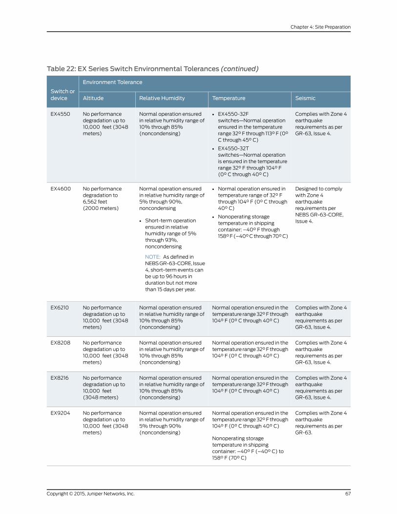
Table 22: EX Series Switch Environmental Tolerances (continued)
Environment Tolerance
Switch ordevice SeismicTemperatureRelative HumidityAltitude
Complies with Zone 4earthquakerequirements as perGR-63, Issue 4.
• EX4550-32Fswitches—Normal operationensured in the temperaturerange 32° F through 113° F (0°C through 45° C)
• EX4550-32Tswitches—Normal operationis ensured in the temperaturerange 32° F through 104° F(0° C through 40° C)
Normal operation ensuredin relative humidity range of10% through 85%(noncondensing)
No performancedegradation up to10,000 feet (3048meters)
EX4550
Designed to complywith Zone 4earthquakerequirements perNEBS GR-63-CORE,Issue 4.
• Normal operation ensured intemperature range of 32° Fthrough 104° F (0° C through40° C)
• Nonoperating storagetemperature in shippingcontainer: –40° F through158°F(–40°Cthrough70°C)
Normal operation ensuredin relative humidity range of5% through 90%,noncondensing
• Short-term operationensured in relativehumidity range of 5%through 93%,noncondensing
NOTE: As defined inNEBSGR-63-CORE, Issue4, short-term events canbe up to 96 hours induration but not morethan 15 days per year.
No performancedegradation to6,562 feet(2000meters)
EX4600
Complies with Zone 4earthquakerequirements as perGR-63, Issue 4.
Normal operation ensured in thetemperature range32°F through104° F (0° C through 40° C)
Normal operation ensuredin relative humidity range of10% through 85%(noncondensing)
No performancedegradation up to10,000 feet (3048meters)
EX6210
Complies with Zone 4earthquakerequirements as perGR-63, Issue 4.
Normal operation ensured in thetemperature range32°F through104° F (0° C through 40° C)
Normal operation ensuredin relative humidity range of10% through 85%(noncondensing)
No performancedegradation up to10,000 feet (3048meters)
EX8208
Complies with Zone 4earthquakerequirements as perGR-63, Issue 4.
Normal operation ensured in thetemperature range32°F through104° F (0° C through 40° C)
Normal operation ensuredin relative humidity range of10% through 85%(noncondensing)
No performancedegradation up to10,000 feet(3048meters)
EX8216
Complies with Zone 4earthquakerequirements as perGR-63.
Normal operation ensured in thetemperature range32°F through104° F (0° C through 40° C)
Nonoperating storagetemperature in shippingcontainer: –40° F (–40° C) to158° F (70° C)
Normal operation ensuredin relative humidity range of5% through 90%(noncondensing)
No performancedegradation up to10,000 feet (3048meters)
EX9204
67Copyright © 2015, Juniper Networks, Inc.
Chapter 4: Site Preparation
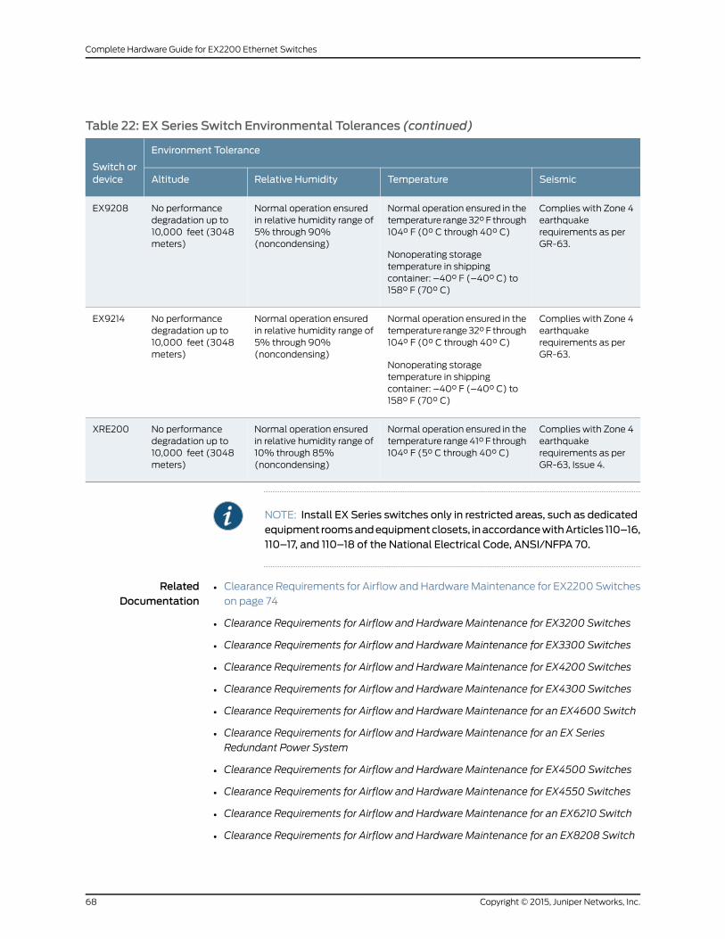
Table 22: EX Series Switch Environmental Tolerances (continued)
Environment Tolerance
Switch ordevice SeismicTemperatureRelative HumidityAltitude
Complies with Zone 4earthquakerequirements as perGR-63.
Normal operation ensured in thetemperature range32°F through104° F (0° C through 40° C)
Nonoperating storagetemperature in shippingcontainer: –40° F (–40° C) to158° F (70° C)
Normal operation ensuredin relative humidity range of5% through 90%(noncondensing)
No performancedegradation up to10,000 feet (3048meters)
EX9208
Complies with Zone 4earthquakerequirements as perGR-63.
Normal operation ensured in thetemperature range32°F through104° F (0° C through 40° C)
Nonoperating storagetemperature in shippingcontainer: –40° F (–40° C) to158° F (70° C)
Normal operation ensuredin relative humidity range of5% through 90%(noncondensing)
No performancedegradation up to10,000 feet (3048meters)
EX9214
Complies with Zone 4earthquakerequirements as perGR-63, Issue 4.
Normal operation ensured in thetemperature range41° F through104° F (5° C through 40° C)
Normal operation ensuredin relative humidity range of10% through 85%(noncondensing)
No performancedegradation up to10,000 feet (3048meters)
XRE200
NOTE: Install EX Series switches only in restricted areas, such as dedicatedequipment roomsandequipmentclosets, inaccordancewithArticles 110–16,110–17, and 110–18 of the National Electrical Code, ANSI/NFPA 70.
RelatedDocumentation
• Clearance Requirements for Airflow and HardwareMaintenance for EX2200 Switches
on page 74
• Clearance Requirements for Airflow and Hardware Maintenance for EX3200 Switches
• Clearance Requirements for Airflow and Hardware Maintenance for EX3300 Switches
• Clearance Requirements for Airflow and Hardware Maintenance for EX4200 Switches
• Clearance Requirements for Airflow and Hardware Maintenance for EX4300 Switches
• Clearance Requirements for Airflow and Hardware Maintenance for an EX4600 Switch
• Clearance Requirements for Airflow and Hardware Maintenance for an EX Series
Redundant Power System
• Clearance Requirements for Airflow and Hardware Maintenance for EX4500 Switches
• Clearance Requirements for Airflow and Hardware Maintenance for EX4550 Switches
• Clearance Requirements for Airflow and Hardware Maintenance for an EX6210 Switch
• Clearance Requirements for Airflow and Hardware Maintenance for an EX8208 Switch
Copyright © 2015, Juniper Networks, Inc.68
Complete Hardware Guide for EX2200 Ethernet Switches

• Clearance Requirements for Airflow and Hardware Maintenance for an EX8216 Switch
• Clearance Requirements for Airflow and Hardware Maintenance for an EX9204 Switch
• Clearance Requirements for Airflow and Hardware Maintenance for an EX9208 Switch
• Clearance Requirements for Airflow and Hardware Maintenance for an EX9214 Switch
69Copyright © 2015, Juniper Networks, Inc.
Chapter 4: Site Preparation

Copyright © 2015, Juniper Networks, Inc.70
Complete Hardware Guide for EX2200 Ethernet Switches

CHAPTER 5
Mounting and Clearance Requirements
• Rack Requirements for EX2200 Switches on page 71
• Cabinet Requirements for EX2200 Switches on page 72
• Requirements for Mounting an EX2200 Switch on a Desktop orWall on page 73
• Clearance Requirements for Airflow and Hardware Maintenance for EX2200
Switches on page 74
Rack Requirements for EX2200 Switches
You canmount the EX2200 switches on two-post racks or four-post racks.
Rack requirements consist of:
• Rack type
• Mounting bracket hole spacing
• Rack size and strength
• Rack connection to the building structure
Table 23 on page 71 provides the rack requirements and specifications for the switch.
Table 23: Rack Requirements and Specifications for the Switch
GuidelinesRack Requirement
Use a two-post rack or a four-post rack. You canmount the switch on any two-post or four-postrack that provides bracket holes or hole patterns spaced at 1 U (1.75 in./4.45 cm) increments andthat meets the size and strength requirements to support the weight.
AU is the standard rackunit defined inCabinets, Racks, Panels, andAssociatedEquipment (documentnumber EIA-310–D) published by the Electronics Industry Association(http://www.ecianow.org/standards-practices/standards/) .
The rack must meet the strength requirements to support the weight of the chassis.
Rack type
The holes in themounting brackets are spaced at 1 U (1.75 in. or 4.45 cm), so that the switch can bemounted in any rack that provides holes spaced at that distance.
Mounting bracket holespacing
71Copyright © 2015, Juniper Networks, Inc.
Table 23: Rack Requirements and Specifications for the Switch (continued)
GuidelinesRack Requirement
• Ensure that the rack complies with the standard defined for 19-in. rack as defined in Cabinets,Racks, Panels, and Associated Equipment (document number EIA-310–D) published by theElectronics IndustryAssociation (http://www.ecianow.org/standards-practices/standards/).
• Ensure that the rack rails are spacedwidely enough to accommodate the switch chassis' externaldimensions . The outer edges of the front-mounting brackets extend the width of the chassis to19 in. (48.2 cm).
• The rack must be strong enough to support the weight of the switch.
• Ensure that the spacing of rails and adjacent racks allows for the proper clearance around theswitch and rack.
Rack size and strength
• Secure the rack to the building structure.
• If earthquakes are a possibility in your geographical area, secure the rack to the floor.
• Secure the rack to the ceiling brackets as well as wall or floor brackets for maximum stability.
Rack connection tobuilding structure
One pair ofmounting brackets formounting the switch on two posts of a rack is supplied
with each switch. For mounting the switch on four posts of a rack or cabinet, you can
order a four-post rack-mount kit separately.
NOTE: Mounting brackets are not supplied with EX2200-C switch; they areseparately orderable.
RelatedDocumentation
Chassis Physical Specifications for EX2200 Switches on page 9•
• Clearance Requirements for Airflow and HardwareMaintenance for EX2200 Switches
on page 74
• Rack-Mounting and Cabinet-MountingWarnings on page 184
• Mounting an EX2200 Switch on Two Posts of a Rack or Cabinet on page 95
• Mounting an EX2200 Switch on Four Posts of a Rack or Cabinet on page 98
• Mounting an EX2200 Switch in a Recessed Position in a Rack or Cabinet on page 102
Cabinet Requirements for EX2200 Switches
You canmount the switch in a cabinet that contains a 19-in. rack.
Cabinet requirements consist of:
• Cabinet size
• Clearance requirements
• Cabinet airflow requirements
Table 24 on page 73 provides the cabinet requirements and specifications for the switch.
Copyright © 2015, Juniper Networks, Inc.72
Complete Hardware Guide for EX2200 Ethernet Switches
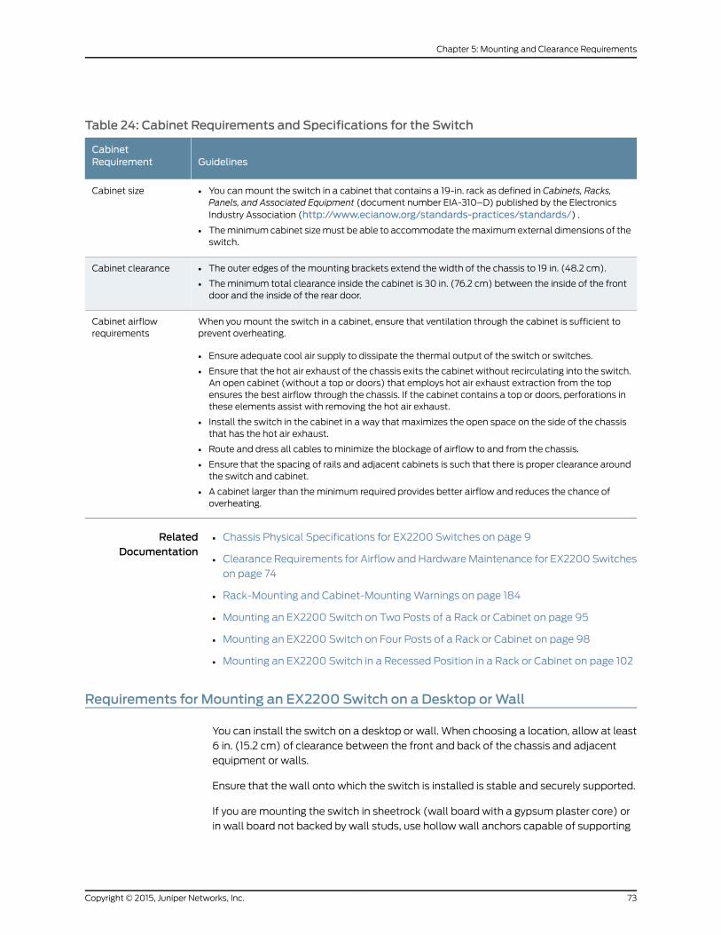
Table 24: Cabinet Requirements and Specifications for the Switch
GuidelinesCabinetRequirement
• You canmount the switch in a cabinet that contains a 19-in. rack as defined in Cabinets, Racks,Panels, and Associated Equipment (document number EIA-310–D) published by the ElectronicsIndustry Association (http://www.ecianow.org/standards-practices/standards/) .
• Theminimumcabinet sizemust be able to accommodate themaximumexternal dimensions of theswitch.
Cabinet size
• The outer edges of the mounting brackets extend the width of the chassis to 19 in. (48.2 cm).
• Theminimum total clearance inside the cabinet is 30 in. (76.2 cm) between the inside of the frontdoor and the inside of the rear door.
Cabinet clearance
When youmount the switch in a cabinet, ensure that ventilation through the cabinet is sufficient toprevent overheating.
• Ensure adequate cool air supply to dissipate the thermal output of the switch or switches.
• Ensure that the hot air exhaust of the chassis exits the cabinet without recirculating into the switch.An open cabinet (without a top or doors) that employs hot air exhaust extraction from the topensures the best airflow through the chassis. If the cabinet contains a top or doors, perforations inthese elements assist with removing the hot air exhaust.
• Install the switch in the cabinet in a way that maximizes the open space on the side of the chassisthat has the hot air exhaust.
• Route and dress all cables to minimize the blockage of airflow to and from the chassis.
• Ensure that the spacing of rails and adjacent cabinets is such that there is proper clearance aroundthe switch and cabinet.
• A cabinet larger than theminimum required provides better airflow and reduces the chance ofoverheating.
Cabinet airflowrequirements
RelatedDocumentation
Chassis Physical Specifications for EX2200 Switches on page 9•
• Clearance Requirements for Airflow and HardwareMaintenance for EX2200 Switches
on page 74
• Rack-Mounting and Cabinet-MountingWarnings on page 184
• Mounting an EX2200 Switch on Two Posts of a Rack or Cabinet on page 95
• Mounting an EX2200 Switch on Four Posts of a Rack or Cabinet on page 98
• Mounting an EX2200 Switch in a Recessed Position in a Rack or Cabinet on page 102
Requirements for Mounting an EX2200 Switch on a Desktop orWall
You can install the switch on a desktop or wall. When choosing a location, allow at least
6 in. (15.2 cm) of clearance between the front and back of the chassis and adjacent
equipment or walls.
Ensure that the wall onto which the switch is installed is stable and securely supported.
If you are mounting the switch in sheetrock (wall board with a gypsum plaster core) or
in wall board not backed by wall studs, use hollow wall anchors capable of supporting
73Copyright © 2015, Juniper Networks, Inc.
Chapter 5: Mounting and Clearance Requirements
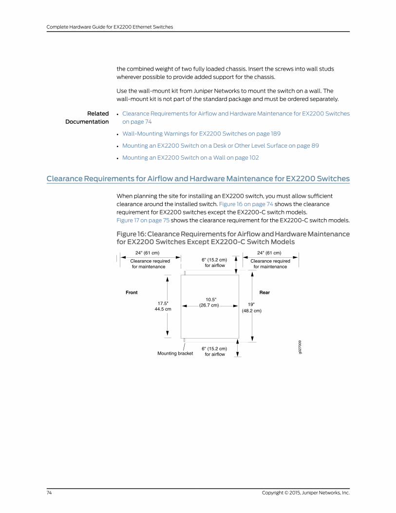
the combined weight of two fully loaded chassis. Insert the screws into wall studs
wherever possible to provide added support for the chassis.
Use the wall-mount kit from Juniper Networks to mount the switch on a wall. The
wall-mount kit is not part of the standard package andmust be ordered separately.
RelatedDocumentation
Clearance Requirements for Airflow and HardwareMaintenance for EX2200 Switches
on page 74
•
• Wall-MountingWarnings for EX2200 Switches on page 189
• Mounting an EX2200 Switch on a Desk or Other Level Surface on page 89
• Mounting an EX2200 Switch on aWall on page 102
ClearanceRequirements for AirflowandHardwareMaintenance for EX2200Switches
When planning the site for installing an EX2200 switch, youmust allow sufficient
clearance around the installed switch. Figure 16 on page 74 shows the clearance
requirement for EX2200 switches except the EX2200-C switch models.
Figure 17 on page 75 shows the clearance requirement for the EX2200-C switchmodels.
Figure 16:ClearanceRequirements forAirflowandHardwareMaintenancefor EX2200 Switches Except EX2200-C SwitchModels
g027
009
Mounting bracket6" (15.2 cm)
for airflow
RearFront
17.5"44.5 cm
10.5"(26.7 cm)
Clearance requiredClearance requiredfor maintenancefor maintenance
24" (61 cm) 24" (61 cm)
6" (15.2 cm)for airflow
19"(48.2 cm)
Copyright © 2015, Juniper Networks, Inc.74
Complete Hardware Guide for EX2200 Ethernet Switches
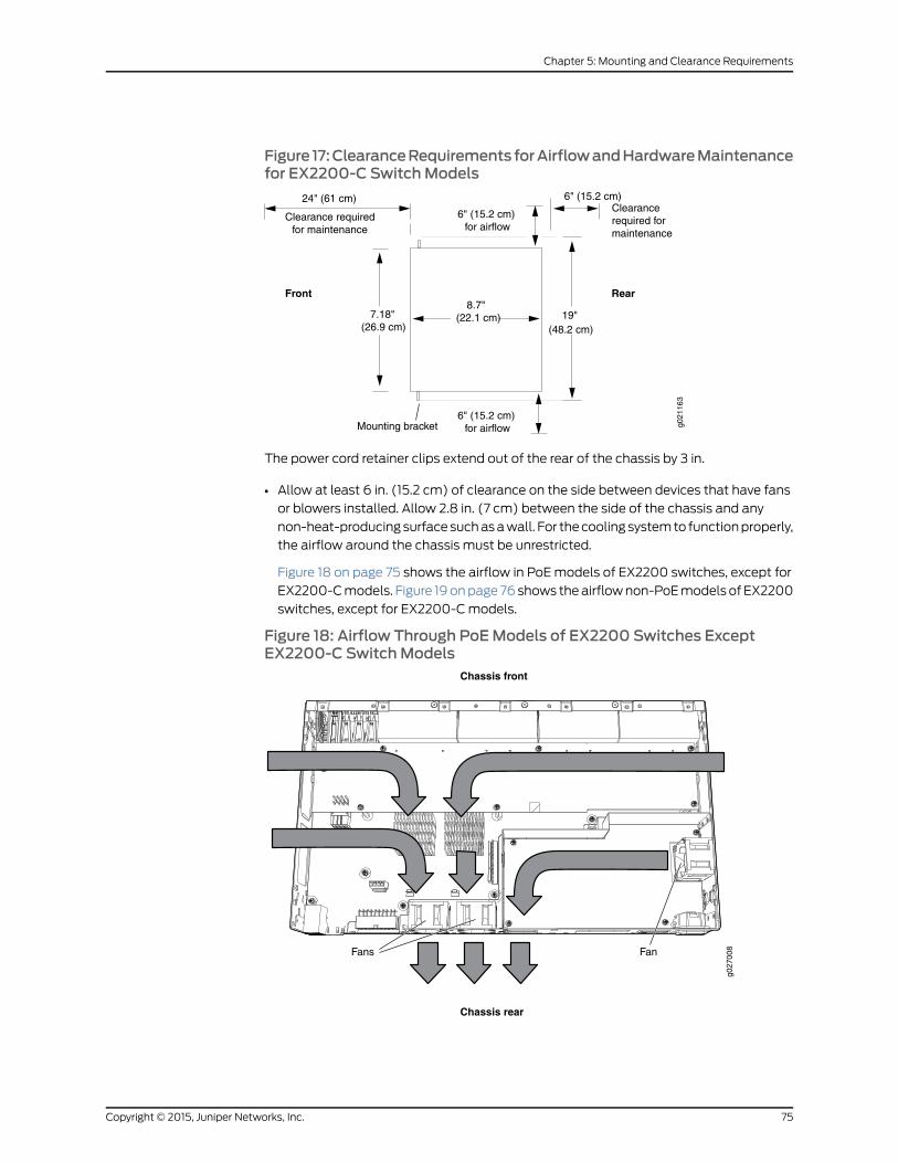
Figure 17:ClearanceRequirements forAirflowandHardwareMaintenancefor EX2200-C SwitchModels
g021
163
Mounting bracket6" (15.2 cm)
for airflow
RearFront
7.18"(26.9 cm)
8.7"(22.1 cm)
Clearancerequired formaintenance
Clearance requiredfor maintenance
24" (61 cm)
6" (15.2 cm)
6" (15.2 cm)
for airflow
19"(48.2 cm)
The power cord retainer clips extend out of the rear of the chassis by 3 in.
• Allow at least 6 in. (15.2 cm) of clearance on the side between devices that have fans
or blowers installed. Allow 2.8 in. (7 cm) between the side of the chassis and any
non-heat-producingsurfacesuchasawall. For thecooling systemto functionproperly,
the airflow around the chassis must be unrestricted.
Figure 18 on page 75 shows the airflow in PoEmodels of EX2200 switches, except for
EX2200-Cmodels. Figure 19onpage 76 shows theairflownon-PoEmodels of EX2200
switches, except for EX2200-Cmodels.
Figure 18: Airflow Through PoEModels of EX2200 Switches ExceptEX2200-C SwitchModels
g027
008
Chassis rear
Chassis front
Fans Fan
75Copyright © 2015, Juniper Networks, Inc.
Chapter 5: Mounting and Clearance Requirements
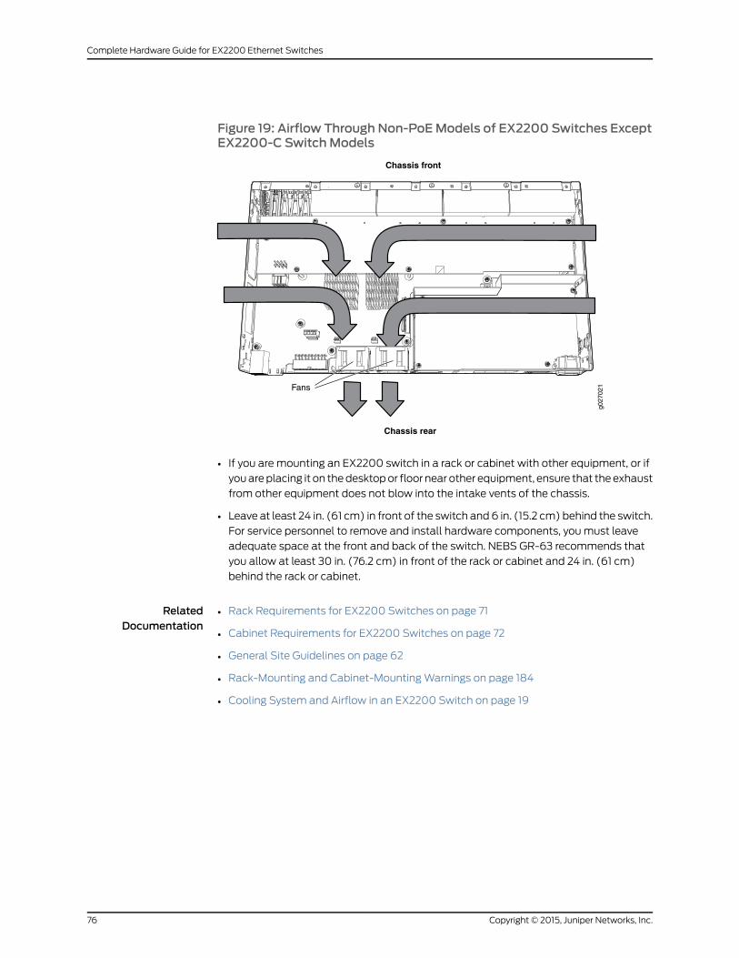
Figure 19: Airflow Through Non-PoEModels of EX2200 Switches ExceptEX2200-C SwitchModels
g027
021
Chassis rear
Chassis front
Fans
• If you are mounting an EX2200 switch in a rack or cabinet with other equipment, or if
youareplacing it on thedesktopor floor near other equipment, ensure that theexhaust
from other equipment does not blow into the intake vents of the chassis.
• Leave at least 24 in. (61 cm) in front of the switch and6 in. (15.2 cm) behind the switch.
For service personnel to remove and install hardware components, youmust leave
adequate space at the front and back of the switch. NEBS GR-63 recommends that
you allow at least 30 in. (76.2 cm) in front of the rack or cabinet and 24 in. (61 cm)
behind the rack or cabinet.
RelatedDocumentation
• Rack Requirements for EX2200 Switches on page 71
• Cabinet Requirements for EX2200 Switches on page 72
• General Site Guidelines on page 62
• Rack-Mounting and Cabinet-MountingWarnings on page 184
• Cooling System and Airflow in an EX2200 Switch on page 19
Copyright © 2015, Juniper Networks, Inc.76
Complete Hardware Guide for EX2200 Ethernet Switches

CHAPTER 6
Cable Specifications
• Network Cable Specifications for EX2200 Switches on page 77
Network Cable Specifications for EX2200 Switches
EX2200 switches have interfaces that use various types of network cables.
For instructions on connecting the switch to a network for out-of-bandmanagement
using an Ethernet cablewith an RJ-45 connector, see “Connecting a Switch to aNetwork
for Out-of-Band Management” on page 127.
For instructions on connecting the switch to amanagement console using an Ethernet
cable with an RJ-45 connector, see “Connecting a Switch to aManagement Console” on
page 129.
For instructions on connecting a fiber-optic cable to the switch, see “Connecting a
Fiber-Optic Cable to a Switch” on page 133.
RelatedDocumentation
• Management Port Connector Pinout Information for an EX2200 Switch on page 25
• Console Port Connector Pinout Information for an EX Series Switch on page 23
• EX2200 Switches Hardware Overview on page 3
77Copyright © 2015, Juniper Networks, Inc.

Copyright © 2015, Juniper Networks, Inc.78
Complete Hardware Guide for EX2200 Ethernet Switches

CHAPTER 7
Planning Power Requirements
• Power Specifications for EX2200 Switches on page 79
• AC Power Cord Specifications for EX2200 Switches on page 80
Power Specifications for EX2200 Switches
This topic describes the power supply electrical specifications for EX2200 switches.
Table 25 on page 79 provides the AC power supply electrical specifications for EX2200
switches.
Table 26 on page 79 provides the DC power supply electrical specifications for EX2200
switches.
Table 25: AC Power Supply Electrical Specifications for EX2200 Switches
SpecificationItem
100 through 240 VACAC input voltage
50 Hz/60 Hz nominalAC input line frequency
• 7 A at 100 VAC and 2.9 A at 230 VAC (for switches with ports equipped forPoE)
• 1.8 A at 100 VAC and 0.5 A at 230 VAC (for switches with no ports equippedfor PoE)
AC system current rating
Table 26: DC Power Supply Electrical Specifications for EX2200 Switches
SpecificationItem
36 through 75 VDCDC input voltage
3.5 AmaximumDC input current
100WPower supply output
1 msminimumOutput holdup time
79Copyright © 2015, Juniper Networks, Inc.
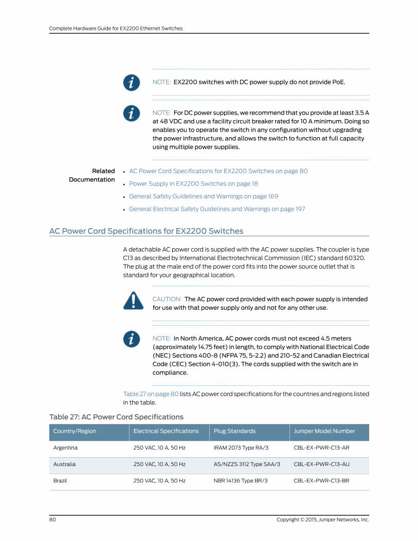
NOTE: EX2200 switches with DC power supply do not provide PoE.
NOTE: ForDCpower supplies,we recommend that youprovide at least 3.5Aat 48 VDC and use a facility circuit breaker rated for 10 Aminimum. Doing soenables you to operate the switch in any configuration without upgradingthe power infrastructure, and allows the switch to function at full capacityusingmultiple power supplies.
RelatedDocumentation
AC Power Cord Specifications for EX2200 Switches on page 80•
• Power Supply in EX2200 Switches on page 18
• General Safety Guidelines andWarnings on page 169
• General Electrical Safety Guidelines andWarnings on page 197
AC Power Cord Specifications for EX2200 Switches
A detachable AC power cord is supplied with the AC power supplies. The coupler is type
C13 as described by International Electrotechnical Commission (IEC) standard 60320.
The plug at the male end of the power cord fits into the power source outlet that is
standard for your geographical location.
CAUTION: The AC power cord provided with each power supply is intendedfor use with that power supply only and not for any other use.
NOTE: In North America, AC power cordsmust not exceed 4.5meters(approximately 14.75 feet) in length, to complywith National Electrical Code(NEC) Sections 400-8 (NFPA 75, 5-2.2) and 210-52 and Canadian ElectricalCode (CEC) Section 4-010(3). The cords supplied with the switch are incompliance.
Table 27onpage80 listsACpower cord specifications for the countries and regions listed
in the table.
Table 27: AC Power Cord Specifications
Juniper Model NumberPlug StandardsElectrical SpecificationsCountry/Region
CBL-EX-PWR-C13-ARIRAM 2073 Type RA/3250 VAC, 10 A, 50 HzArgentina
CBL-EX-PWR-C13-AUAS/NZZS 3112 Type SAA/3250 VAC, 10 A, 50 HzAustralia
CBL-EX-PWR-C13-BRNBR 14136 Type BR/3250 VAC, 10 A, 50 HzBrazil
Copyright © 2015, Juniper Networks, Inc.80
Complete Hardware Guide for EX2200 Ethernet Switches
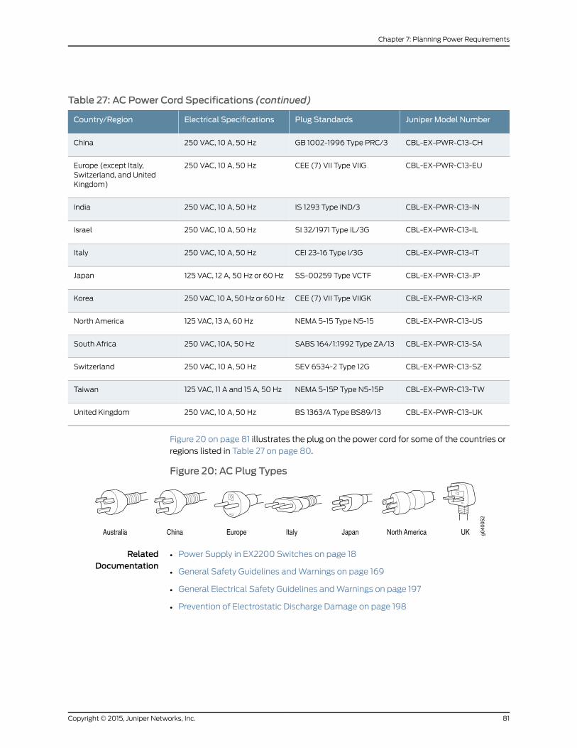
Table 27: AC Power Cord Specifications (continued)
Juniper Model NumberPlug StandardsElectrical SpecificationsCountry/Region
CBL-EX-PWR-C13-CHGB 1002-1996 Type PRC/3250 VAC, 10 A, 50 HzChina
CBL-EX-PWR-C13-EUCEE (7) VII Type VIIG250 VAC, 10 A, 50 HzEurope (except Italy,Switzerland, and UnitedKingdom)
CBL-EX-PWR-C13-INIS 1293 Type IND/3250 VAC, 10 A, 50 HzIndia
CBL-EX-PWR-C13-ILSI 32/1971 Type IL/3G250 VAC, 10 A, 50 HzIsrael
CBL-EX-PWR-C13-ITCEI 23-16 Type I/3G250 VAC, 10 A, 50 HzItaly
CBL-EX-PWR-C13-JPSS-00259 Type VCTF125 VAC, 12 A, 50 Hz or 60 HzJapan
CBL-EX-PWR-C13-KRCEE (7) VII Type VIIGK250VAC, 10A, 50Hz or 60HzKorea
CBL-EX-PWR-C13-USNEMA 5-15 Type N5-15125 VAC, 13 A, 60 HzNorth America
CBL-EX-PWR-C13-SASABS 164/1:1992 Type ZA/13250 VAC, 10A, 50 HzSouth Africa
CBL-EX-PWR-C13-SZSEV 6534-2 Type 12G250 VAC, 10 A, 50 HzSwitzerland
CBL-EX-PWR-C13-TWNEMA 5-15P Type N5-15P125 VAC, 11 A and 15 A, 50 HzTaiwan
CBL-EX-PWR-C13-UKBS 1363/A Type BS89/13250 VAC, 10 A, 50 HzUnited Kingdom
Figure 20 on page 81 illustrates the plug on the power cord for some of the countries or
regions listed in Table 27 on page 80.
Figure 20: AC Plug Types
RelatedDocumentation
• Power Supply in EX2200 Switches on page 18
• General Safety Guidelines andWarnings on page 169
• General Electrical Safety Guidelines andWarnings on page 197
• Prevention of Electrostatic Discharge Damage on page 198
81Copyright © 2015, Juniper Networks, Inc.
Chapter 7: Planning Power Requirements

Copyright © 2015, Juniper Networks, Inc.82
Complete Hardware Guide for EX2200 Ethernet Switches

PART 3
Installing and Connecting the Switch andSwitch Components
• Installing the Switch on page 85
• Installing Switch Components on page 113
• Connecting the Switch on page 117
• Performing Initial Configuration on page 135
83Copyright © 2015, Juniper Networks, Inc.

Copyright © 2015, Juniper Networks, Inc.84
Complete Hardware Guide for EX2200 Ethernet Switches

CHAPTER 8
Installing the Switch
• Installing and Connecting an EX2200 Switch on page 85
• Unpacking an EX2200 Switch on page 86
• Parts Inventory (Packing List) for an EX2200 Switch on page 87
• Mounting an EX2200 Switch on page 88
• Mounting an EX2200 Switch on a Desk or Other Level Surface on page 89
• Mounting an EX2200 Switch On or Under a Desk Using Screws on page 92
• Mounting an EX2200 Switch on Two Posts of a Rack or Cabinet on page 95
• Mounting an EX2200 Switch on Four Posts of a Rack or Cabinet on page 98
• Mounting an EX2200 Switch in a Recessed Position in a Rack or Cabinet on page 102
• Mounting an EX2200 Switch on aWall on page 102
• Mounting an EX2200 Switch Using the Magnet Mount on page 109
Installing and Connecting an EX2200 Switch
To install and connect an EX2200 switch:
1. Follow instructions in “Unpacking an EX2200 Switch” on page 86.
2. Mount the switch by following instructions appropriate for your site:
• “Mounting anEX2200Switch onTwoPosts of aRack or Cabinet” onpage95 (using
the mounting brackets provided)
• “MountinganEX2200SwitchonFourPosts of aRackorCabinet” onpage98(using
the separately orderable four-post rack-mount kit)
• “MountinganEX2200Switch inaRecessedPosition inaRackorCabinet”onpage 102
(using the 2-in.-recess front brackets from the separately orderable four-post
rack-mount kit)
• “Mounting an EX2200 Switch on a Desk or Other Level Surface” on page 89 (using
the rubber feet provided)
• “MountinganEX2200SwitchonaWall” onpage 102(using thescrewsor separately
orderable wall-mount kit)
85Copyright © 2015, Juniper Networks, Inc.

• “Mounting an EX2200 Switch On or Under a Desk Using Screws” on page 92 (using
the desk/wall mounting screws)
• “Mounting an EX2200 Switch Using the Magnet Mount” on page 109 (using the
separately orderable magnet sheet)
3. Follow instructions in “Connecting Earth Ground to an EX Series Switch” on page 117.
4. Follow instructions in “Connecting AC Power to an EX2200 Switch” on page 123 or
“Connecting DC Power to an EX2200 Switch” on page 125.
5. Perform initial configuration of the switch by following instructions in “Connecting
andConfiguring anEXSeriesSwitch (CLI Procedure)” onpage 139or “Connecting and
Configuring an EX Series Switch (J-Web Procedure)” on page 142.
6. Set the switch’s management options by following the appropriate instructions:
• Connecting a Switch to a Network for Out-of-Band Management on page 127
• Connecting a Switch to a Management Console on page 129
RelatedDocumentation
Rack Requirements for EX2200 Switches on page 71•
• Cabinet Requirements for EX2200 Switches on page 72
• Clearance Requirements for Airflow and HardwareMaintenance for EX2200 Switches
on page 74
Unpacking an EX2200 Switch
The EX2200 switches are shipped in a cardboard carton, secured with foam packing
material. The carton also contains an accessory box.
CAUTION: EX2200 switches aremaximally protected inside the shippingcarton. Do not unpack the switches until you are ready to begin installation.
To unpack the switch:
1. Move the shipping carton to a staging area as close to the installation site as possible,
but where you have enough room to remove the system components.
2. Position the carton so that the arrows are pointing up.
3. Open the top flaps on the shipping carton.
4. Remove the accessory box and verify the contents in it against the parts inventory on
the label attached to the carton.
5. Pull out the packing material holding the switch in place.
Copyright © 2015, Juniper Networks, Inc.86
Complete Hardware Guide for EX2200 Ethernet Switches
6. Verify the chassis components received against the packing list included with the
switch. An inventory of parts provided with the switch is provided in “Parts Inventory
(Packing List) for an EX2200 Switch” on page 87.
7. Save the shipping carton and packing materials in case you need to move or ship the
switch later.
RelatedDocumentation
Mounting an EX2200 Switch on page 88•
• Installing and Connecting an EX2200 Switch on page 85
• Connecting and Configuring an EX Series Switch (CLI Procedure) on page 139
• Connecting and Configuring an EX Series Switch (J-Web Procedure) on page 142
Parts Inventory (Packing List) for an EX2200 Switch
The EX2200 switches are shipped in a cardboard carton, secured with foam packing
material. The carton also contains an accessory box.
The switch shipment includes a packing list. Check the parts you receive in the switch
shipping carton against the items on the packing list. The parts shipped depend on the
configuration you order.
If any part on the packing list is missing, contact your customer service representative or
contact Juniper customer care fromwithin the U.S. or Canada by telephone at
1–800–638–8296. For international-dial or direct-dial options in countries without
toll-free numbers, see http://www.juniper.net/support/requesting-support.html .
Table 28 on page 87 lists the parts and their quantities in the packing list.
Table 28: Parts List for EX2200 Switches
QuantityComponent
1Switch with built-in power supply
1AC power cord appropriate for your geographical location (only for AC switch models)
1Power cord retainer clip (only for AC switch models)
2Mounting brackets:
• EX2200 switch—provided
• EX2200-C switch—separately orderable
8Mounting screws to attach themounting brackets to the switch chassis:
• EX2200 switch—provided
• EX2200-C switch—separately orderable
4Rubber feet
87Copyright © 2015, Juniper Networks, Inc.
Chapter 8: Installing the Switch
Table 28: Parts List for EX2200 Switches (continued)
QuantityComponent
1RJ-45 cable and RJ-45 to DB-9 serial port adapter
-Cable guard and 3 number-8 Phillips truss-head screws (EX2200-Cmodels only and separately orderable)
1Quick Start installation instructions
1Juniper Networks ProductWarranty
1End User License Agreement
NOTE: Youmust providemounting screws that are appropriate for your rackor cabinet tomount the chassis on a rack or a cabinet.
RelatedDocumentation
Unpacking an EX2200 Switch on page 86•
• EX2200 Switches Hardware Overview on page 3
Mounting an EX2200 Switch
Table 29 on page 88 lists the methods you can use to mount an EX2200 switch.
Table 29: EX2200 SwitchMountingMethods
CommentsSwitch ModelMounting Method
On a desk or other level surface by using rubber feet providedwiththe switch
• EX2200
• EX2200-C
Desk or other level surface(using rubber feet)
On or under a desk or other level surface by using screwsEX2200-CDesk or other level surface(using screws)
On two posts in a 19-in. rack or cabinet by using the mountingbrackets.
• EX2200
• EX2200-C
Two-post rack or cabinet
• On four posts in a 19-in. rack or cabinet by using the separatelyorderable four-post rack-mount kit
• On two posts in a 19-in. rack or cabinet by using the two postrack mounting brackets.
• EX2200
• EX2200-C
Four-post rack or cabinet
In a position recessed 2 in. from the front of a 19-in. rack or cabinetby using the 2-in.-recess front brackets in the separately orderablefour-post rack-mount kit. Youcanmount theswitch in this recessedposition on two-post or four-post racks and cabinets
EX2200Recessed position
Copyright © 2015, Juniper Networks, Inc.88
Complete Hardware Guide for EX2200 Ethernet Switches
Table 29: EX2200 SwitchMountingMethods (continued)
CommentsSwitch ModelMounting Method
• On a wall by using screws or separately orderable wall-mountkit
• On a wall by using screws
• EX2200
• EX2200-C
Wall mount
Onorunder a surfacemadeof ferrousmaterial using the separatelyorderable magnet sheet
EX2200-CMagnet mount
WARNING:
Whenmounting an EX2200 switch chassis in a vertical position, orient thefront panel of the chassis downward to ensure proper airflow andmeetsafety requirements in the event of a fire.
•
• Whenwall mounting EX2200-24P and EX2200-48Pmodels, install thewall-mount baffle above the units to reduce the risk of objects orsubstances falling into the air exhaust or power supply, which could causea fire.
The holes in the mounting brackets are placed at 1 U (1.75 in. or 4.45 cm) apart so that
the switch can bemounted in any rack or cabinet that provides holes spaced at that
distance.
See the Related Documentation for detailed descriptions of the various rack or cabinet
mounting options.
RelatedDocumentation
Mounting an EX2200 Switch on Two Posts of a Rack or Cabinet on page 95•
• Mounting an EX2200 Switch on Four Posts of a Rack or Cabinet on page 98
• Mounting an EX2200 Switch in a Recessed Position in a Rack or Cabinet on page 102
• Mounting an EX2200 Switch on a Desk or Other Level Surface on page 89
• Mounting an EX2200 Switch on aWall on page 102
• Mounting an EX2200 Switch On or Under a Desk Using Screws on page 92
• Mounting an EX2200 Switch Using the Magnet Mount on page 109
• Connecting Earth Ground to an EX Series Switch on page 117
Mounting an EX2200 Switch on a Desk or Other Level Surface
YoucanmountanEX2200switchonadeskor other level surfacebyusing the four rubber
feet that are shipped with the switch. The rubber feet stabilize the chassis.
Before mounting the switch on a desk or other level surface:
89Copyright © 2015, Juniper Networks, Inc.
Chapter 8: Installing the Switch
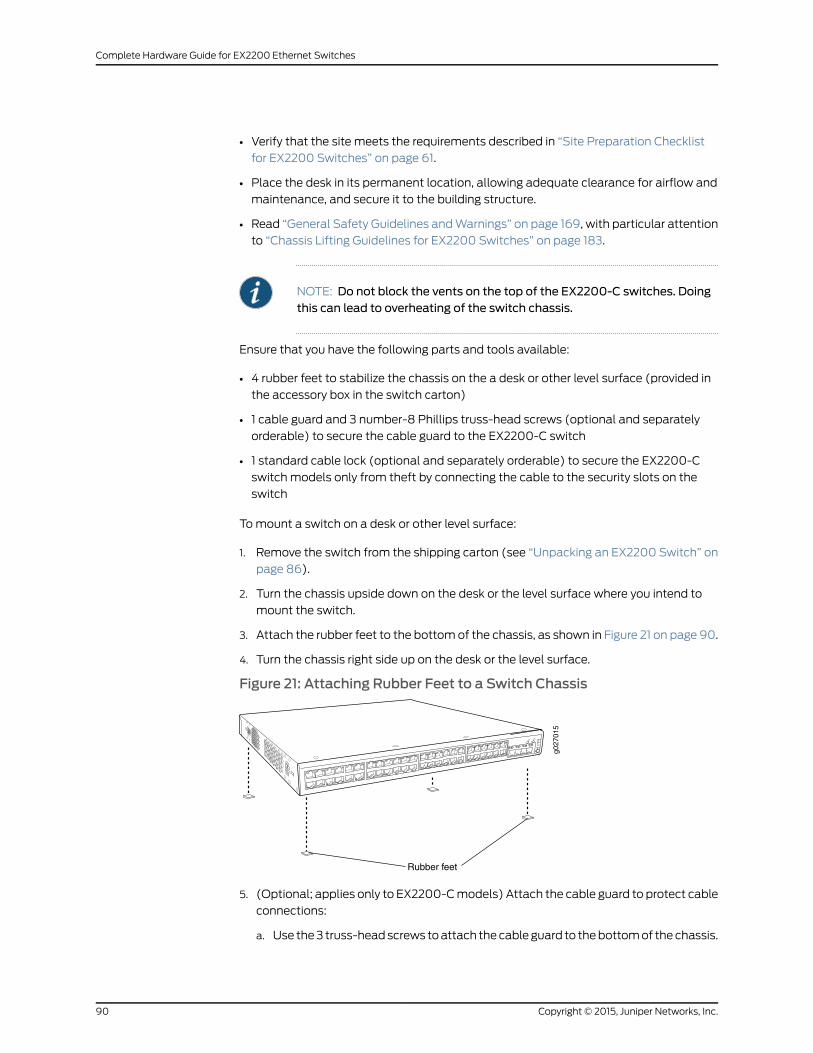
• Verify that the site meets the requirements described in “Site Preparation Checklist
for EX2200 Switches” on page 61.
• Place the desk in its permanent location, allowing adequate clearance for airflow and
maintenance, and secure it to the building structure.
• Read “General Safety Guidelines andWarnings” on page 169, with particular attention
to “Chassis Lifting Guidelines for EX2200 Switches” on page 183.
NOTE: Do not block the vents on the top of the EX2200-C switches. Doingthis can lead to overheating of the switch chassis.
Ensure that you have the following parts and tools available:
• 4 rubber feet to stabilize the chassis on the a desk or other level surface (provided in
the accessory box in the switch carton)
• 1 cable guard and 3 number-8 Phillips truss-head screws (optional and separately
orderable) to secure the cable guard to the EX2200-C switch
• 1 standard cable lock (optional and separately orderable) to secure the EX2200-C
switch models only from theft by connecting the cable to the security slots on the
switch
Tomount a switch on a desk or other level surface:
1. Remove the switch from the shipping carton (see “Unpacking an EX2200 Switch” on
page 86).
2. Turn the chassis upside down on the desk or the level surface where you intend to
mount the switch.
3. Attach the rubber feet to the bottomof the chassis, as shown in Figure 21 on page 90.
4. Turn the chassis right side up on the desk or the level surface.
Figure 21: Attaching Rubber Feet to a Switch Chassis
Rubber feet
g027
015
SYS AL
M SPD
DX
POE
EN
5. (Optional; applies only to EX2200-Cmodels) Attach the cable guard to protect cable
connections:
a. Use the3 truss-headscrews toattach thecableguard to thebottomof thechassis.
Copyright © 2015, Juniper Networks, Inc.90
Complete Hardware Guide for EX2200 Ethernet Switches

b. Use the thumbscrews to tighten or loosen the guard to allow you to insert cables.
See Figure 22 on page 91.
Figure 22: Attaching a Cable Guard to an EX2200-C Switch
g021161
6. (Optional; applies only to EX2200-Cmodels) Attach the standard cable lock to the
security slots on the both sides of the switch:
a. Rope the cable to a desk or a rack and set the lock to unlocked position.
b. Insert the lock into one of the security slot on your chassis and set the lock to the
locked position. See Figure 23 on page 91.
Figure 23: Securing the EX2200-C Switch Using Security Slots
g021160
Security slot
Security cable
RelatedDocumentation
Connecting AC Power to an EX2200 Switch on page 123•
• Connecting DC Power to an EX2200 Switch on page 125
• Connecting and Configuring an EX Series Switch (CLI Procedure) on page 139
• Connecting and Configuring an EX Series Switch (J-Web Procedure) on page 142
• Clearance Requirements for Airflow and HardwareMaintenance for EX2200 Switches
on page 74
91Copyright © 2015, Juniper Networks, Inc.
Chapter 8: Installing the Switch
Mounting an EX2200 Switch On or Under a Desk Using Screws
This topic applies only to the EX2200-C switch, the compact, fanless model.
You canmount an EX2200-C switch on or under a desk or other level surface by using
the flexible mounting slots on the bottom of the chassis to secure the switch.
Before mounting the switch on or under a desk or other lever surface:
• Verify that the site meets the requirements described in “Site Preparation Checklist
for EX2200 Switches” on page 61.
• Place the desk in its permanent location, allowing adequate clearance for airflow and
maintenance, and secure it to the building structure.
• Read “General Safety Guidelines andWarnings” on page 169, with particular attention
to “Chassis Lifting Guidelines for EX2200 Switches” on page 183.
• Remove the switch from the shipping carton (see “Unpacking an EX2200 Switch” on
page 86).
NOTE: Do not block the vents on the top of the EX2200-C switches. Doingthis can lead to overheating of the switch chassis.
Ensure that you have the following parts and tools available:
• 3 desk mounting screws (M4 x 30mm or 8-32 x 1.25 in. Phillips pan-headmachine
screws—not provided)
• Phillips (+) screwdriver, number 2.
• 1 cable guard and 3 number-8 Phillips truss-head screws (optional and separately
orderable) to secure the cable guard to the switch
• 1 standard cable lock (optional and separately orderable) to secure the switch from
theft by connecting the cable to the security slots on the switch
Tomount the switch on or under a desk or other level surface:
1. Drill three holes A, B, and C on or under the desk as shown in Figure 24 on page 93.
Copyright © 2015, Juniper Networks, Inc.92
Complete Hardware Guide for EX2200 Ethernet Switches
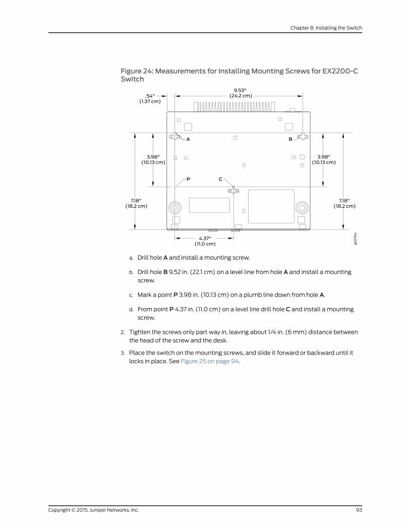
Figure 24: Measurements for Installing Mounting Screws for EX2200-CSwitch
a. Drill hole A and install a mounting screw.
b. Drill hole B 9.52 in. (22.1 cm) on a level line from hole A and install a mountingscrew.
c. Mark a point P 3.98 in. (10.13 cm) on a plumb line down from hole A.
d. From point P 4.37 in. (11.0 cm) on a level line drill hole C and install a mountingscrew.
2. Tighten the screws only part way in, leaving about 1/4 in. (6 mm) distance between
the head of the screw and the desk.
3. Place the switch on themounting screws, and slide it forward or backward until it
locks in place. See Figure 25 on page 94.
93Copyright © 2015, Juniper Networks, Inc.
Chapter 8: Installing the Switch
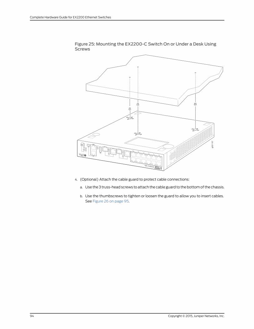
Figure 25: Mounting the EX2200-C Switch On or Under a Desk UsingScrews
g0
21
15
7
4. (Optional) Attach the cable guard to protect cable connections:
a. Use the3 truss-headscrews toattach thecableguard to thebottomof thechassis.
b. Use the thumbscrews to tighten or loosen the guard to allow you to insert cables.
See Figure 26 on page 95.
Copyright © 2015, Juniper Networks, Inc.94
Complete Hardware Guide for EX2200 Ethernet Switches

Figure 26: Attaching a Cable Guard to an EX2200-C Switch
g021161
5. (Optional) Attach the standard cable lock to the security slots on the both sides of
the switch
a. Rope the cable to a desk or a rack and set the lock to unlocked position.
b. Insert the lock into one of the security slot on your chassis and set the lock to the
locked position. See Figure 27 on page 95.
Figure 27: Securing the EX2200-C Switch Using Security Slotsg021160
Security slot
Security cable
RelatedDocumentation
Connecting AC Power to an EX2200 Switch on page 123•
• Connecting and Configuring an EX Series Switch (CLI Procedure) on page 139
• Wall-MountingWarnings for EX2200 Switches on page 189
Mounting an EX2200 Switch on Two Posts of a Rack or Cabinet
You canmount all EX2200 switches on twoposts of a two-post or a four-post 19-in. rack
or cabinet using the mounting brackets and screws provided with all EX2200 switches
except the EX2200-C switches. For EX2200-C switches, mounting brackets and screws
95Copyright © 2015, Juniper Networks, Inc.
Chapter 8: Installing the Switch
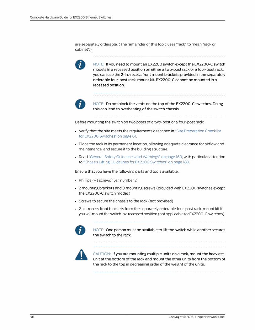
are separately orderable. (The remainder of this topic uses “rack” to mean “rack or
cabinet”.)
NOTE: If you need tomount an EX2200 switch except the EX2200-C switchmodels in a recessed position on either a two-post rack or a four-post rack,you can use the 2-in.-recess frontmount brackets provided in the separatelyorderable four-post rack-mount kit. EX2200-C cannot bemounted in arecessed position.
NOTE: Do not block the vents on the top of the EX2200-C switches. Doingthis can lead to overheating of the switch chassis.
Before mounting the switch on two posts of a two-post or a four-post rack:
• Verify that the site meets the requirements described in “Site Preparation Checklist
for EX2200 Switches” on page 61.
• Place the rack in its permanent location, allowing adequate clearance for airflow and
maintenance, and secure it to the building structure.
• Read “General Safety Guidelines andWarnings” on page 169, with particular attention
to “Chassis Lifting Guidelines for EX2200 Switches” on page 183.
Ensure that you have the following parts and tools available:
• Phillips (+) screwdriver, number 2
• 2mounting brackets and 8mounting screws (provided with EX2200 switches except
the EX2200-C switch model )
• Screws to secure the chassis to the rack (not provided)
• 2-in.-recess front brackets from the separately orderable four-post rack-mount kit if
youwillmount theswitch ina recessedposition(notapplicable forEX2200-Cswitches).
NOTE: Onepersonmust be available to lift the switchwhile another securesthe switch to the rack.
CAUTION: If you aremountingmultiple units on a rack, mount the heaviestunit at the bottom of the rack andmount the other units from the bottom ofthe rack to the top in decreasing order of the weight of the units.
Copyright © 2015, Juniper Networks, Inc.96
Complete Hardware Guide for EX2200 Ethernet Switches
Tomount the switch on two posts of a two-post or a four-post rack:
1. Remove the switch from the shipping carton (see “Unpacking an EX2200 Switch” on
page 86).
2. Place the switch on a flat, stable surface.
3. Align the mounting brackets along the front or rear of the side panels of the switch
chassis depending on how you want to mount the switch. For example, if you want
to front-mount the switch, align the brackets along the front of the chassis.
Figure 28 on page 97 shows attaching the mounting brackets along the front of the
EX2200 switch.
Figure 28: Attaching theMounting Bracket Along the Front of the Switch
g027
019
SYS AL
M SPD
DX
EN
POE
NOTE: The lengthof themountingbracketsdependsontheswitchmodel.
4. Align the bottom holes in the mounting brackets with holes on the side panels of the
switch chassis.
5. Insert the mounting screws into the aligned holes. Tighten the screws.
6. Ensure that the other holes in themounting brackets are alignedwith the holes in the
side panels. Insert a screw in each hole and tighten the screws.
7. Have one person grasp both sides of the switch, lift the switch, and position it in the
rack, aligning themountingbracket holeswith the threadedholes in the rackor cabinet
rail. Align the bottom hole in eachmounting bracket with a hole in each rack rail,
making sure the chassis is level. See Figure 29 on page 98.
97Copyright © 2015, Juniper Networks, Inc.
Chapter 8: Installing the Switch

Figure 29: Mounting the Switch on Two Posts of a Rack
g027
020
Mounting rack
Mounting bracket
8. Have a second person secure the switch to the rack by using the appropriate screws.
Tighten the screws.
9. Ensure that the switch chassis is level by verifying that all screws on one side of the
rack are aligned with the screws on the other side.
RelatedDocumentation
Mounting an EX2200 Switch on Four Posts of a Rack or Cabinet on page 98•
• Connecting Earth Ground to an EX Series Switch on page 117
• Connecting AC Power to an EX2200 Switch on page 123
• Connecting DC Power to an EX2200 Switch on page 125
• Connecting and Configuring an EX Series Switch (CLI Procedure) on page 139
• Connecting and Configuring an EX Series Switch (J-Web Procedure) on page 142
• Mounting an EX2200 Switch in a Recessed Position in a Rack or Cabinet on page 102
• Rack-Mounting and Cabinet-MountingWarnings on page 184
Mounting an EX2200 Switch on Four Posts of a Rack or Cabinet
You canmount an EX2200 switch except an EX2200-C switch model on four posts of
a 19-in. rack or cabinet by using the separately orderable four-post rack-mount kit. (The
remainder of this topic uses “rack” to mean “rack or cabinet.”)
NOTE: EX2200-C switches cannot bemounted on all four posts of a rack.
Copyright © 2015, Juniper Networks, Inc.98
Complete Hardware Guide for EX2200 Ethernet Switches
NOTE: If you need tomount an EX2200 switch except the EX2200-C switchmodel in a recessed position on either a two-post rack or a four-post rack,you can use the 2-in.-recess front-mounting brackets provided in theseparately orderable four-post rack-mount kit. EX2200-C switches cannotbemounted in a recessed position.
Before mounting the switch on four posts of a rack:
• Verify that the site meets the requirements described in “Site Preparation Checklist
for EX2200 Switches” on page 61.
• Place the rack in its permanent location, allowing adequate clearance for airflow and
maintenance, and secure it to the building structure.
• Read “General Safety Guidelines andWarnings” on page 169, with particular attention
to “Chassis Lifting Guidelines for EX2200 Switches” on page 183.
Ensure that you have the following parts and tools available:
• Phillips (+) screwdriver, number 2
• 6 Phillips 4-40 flat-headmounting screws (provided with the four-post rack-mount
kit)
• 8Phillips4x6-mmflat-headmountingscrews(providedwith the four-post rack-mount
kit)
• One pair each of flush or 2-in.-recess front-mounting brackets
• One pair of side mounting-rails
• One pair of rear mounting-blades
• Screws to secure the chassis and the rear mounting-blades to the rack (not provided)
NOTE: Onepersonmust be available to lift the switchwhile another securesit to the rack.
CAUTION: If you aremountingmultiple units on a rack, mount the heaviestunit at the bottom of the rack andmount the other units from the bottom ofthe rack to the top in decreasing order of the weight of the units.
Tomount the switch on four posts of a rack:
1. Remove the switch from the shipping carton (see “Unpacking an EX2200 Switch” on
page 86).
2. Attach the front-mounting brackets (either the flush or the 2-in.-recess brackets) to
the side mounting-rails using 6 Phillips 4-40 flat-headmounting screws. See
Figure 30 on page 100.
99Copyright © 2015, Juniper Networks, Inc.
Chapter 8: Installing the Switch
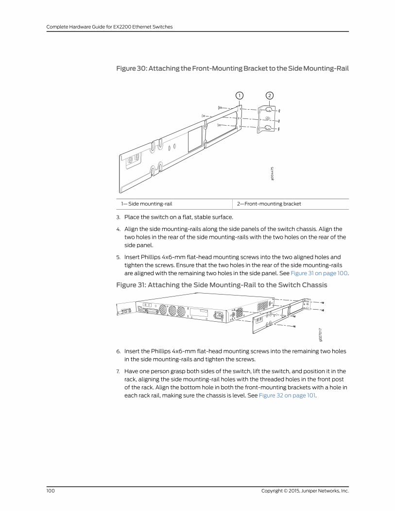
Figure30:AttachingtheFront-MountingBrackettotheSideMounting-Rail
2—1— Front-mounting bracketSide mounting-rail
3. Place the switch on a flat, stable surface.
4. Align the side mounting-rails along the side panels of the switch chassis. Align the
two holes in the rear of the side mounting-rails with the two holes on the rear of the
side panel.
5. Insert Phillips 4x6-mm flat-headmounting screws into the two aligned holes and
tighten the screws. Ensure that the two holes in the rear of the side mounting-rails
are alignedwith the remaining two holes in the side panel. See Figure 31 on page 100.
Figure 31: Attaching the SideMounting-Rail to the Switch Chassis
g027
017
6. Insert the Phillips 4x6-mm flat-headmounting screws into the remaining two holes
in the side mounting-rails and tighten the screws.
7. Have one person grasp both sides of the switch, lift the switch, and position it in the
rack, aligning the side mounting-rail holes with the threaded holes in the front post
of the rack. Align the bottom hole in both the front-mounting brackets with a hole in
each rack rail, making sure the chassis is level. See Figure 32 on page 101.
Copyright © 2015, Juniper Networks, Inc.100
Complete Hardware Guide for EX2200 Ethernet Switches
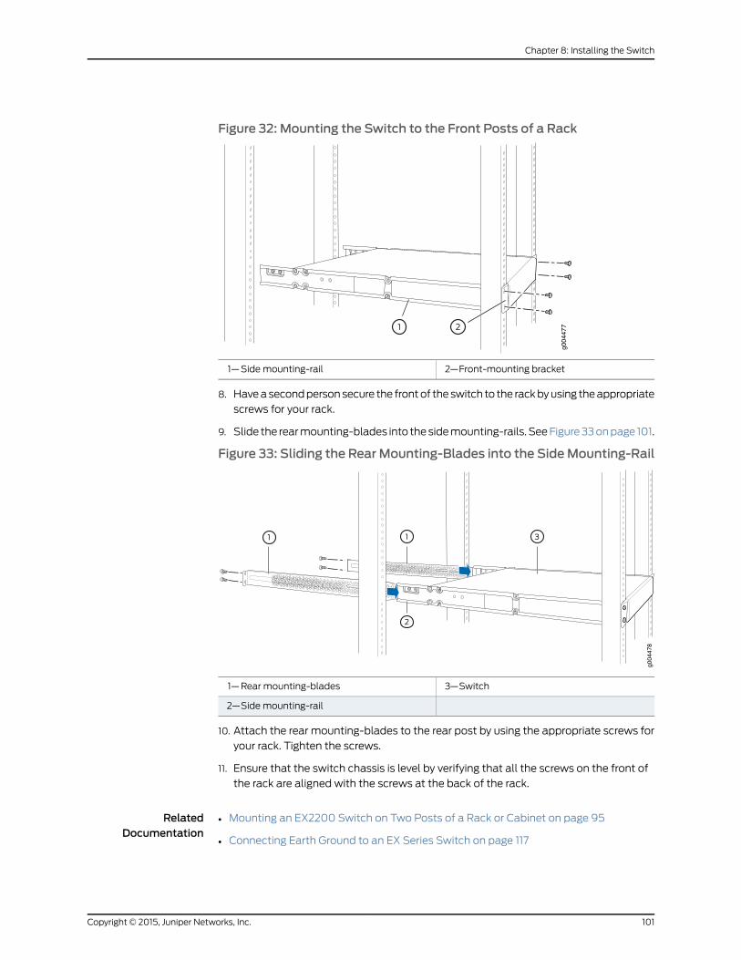
Figure 32: Mounting the Switch to the Front Posts of a Rack
2—1— Front-mounting bracketSide mounting-rail
8. Haveasecondpersonsecure the frontof theswitch to the rackbyusing theappropriate
screws for your rack.
9. Slide the rearmounting-blades into thesidemounting-rails. SeeFigure33onpage 101.
Figure 33: Sliding the Rear Mounting-Blades into the SideMounting-Rail
3—1— SwitchRear mounting-blades
2—Sidemounting-rail
10. Attach the rear mounting-blades to the rear post by using the appropriate screws for
your rack. Tighten the screws.
11. Ensure that the switch chassis is level by verifying that all the screws on the front of
the rack are aligned with the screws at the back of the rack.
RelatedDocumentation
Mounting an EX2200 Switch on Two Posts of a Rack or Cabinet on page 95•
• Connecting Earth Ground to an EX Series Switch on page 117
101Copyright © 2015, Juniper Networks, Inc.
Chapter 8: Installing the Switch
• Connecting AC Power to an EX2200 Switch on page 123
• Connecting DC Power to an EX2200 Switch on page 125
• Connecting and Configuring an EX Series Switch (CLI Procedure) on page 139
• Connecting and Configuring an EX Series Switch (J-Web Procedure) on page 142
• Mounting an EX2200 Switch in a Recessed Position in a Rack or Cabinet on page 102
• Rack-Mounting and Cabinet-MountingWarnings on page 184
Mounting an EX2200 Switch in a Recessed Position in a Rack or Cabinet
YoucanmountanEX2200switchexcept theEX2200-Cswitchmodel ina rackor cabinet
such that the switch is recessed inside the rack from the rack front by 2 inches. You can
use the 2-in.-recess front brackets provided in the separately orderable four-post
rack-mount kit to mount the switch in a recessed position.
Reasons that youmight want to mount the switch in a recessed position include:
• Youaremounting theswitch inacabinetand thecabinetdoorswill not closecompletely
unless the switch is recessed.
• The switch you are mounting has transceivers installed in the uplink ports—the
transceivers in the uplink ports protrude from the front of the switch.
Tomount the switch in a recessed position on four posts, follow the instructions in
“Mounting an EX2200 Switch on Four Posts of a Rack or Cabinet” on page 98. Tomount
the switch in a recessed position on two posts, follow the instructions in “Mounting an
EX2200 Switch on Two Posts of a Rack or Cabinet” on page 95.
RelatedDocumentation
Connecting Earth Ground to an EX Series Switch on page 117•
• Rack-Mounting and Cabinet-MountingWarnings on page 184
Mounting an EX2200 Switch on aWall
This topic describes the process of mounting an EX2200 switch on a wall.
1. Mounting an EX2200 Switch Except the EX2200-C Model on aWall on page 102
2. Mounting an EX2200-C Switch on aWall on page 105
Mounting an EX2200 Switch Except the EX2200-CModel on aWall
YoucanmountanEX2200switchonawall byusing theseparatelyorderablewall-mount
kit.
WARNING:
Copyright © 2015, Juniper Networks, Inc.102
Complete Hardware Guide for EX2200 Ethernet Switches
• Whenmounting an EX2200 switch chassis in a vertical position, orient thefront panel of the chassis downward to ensure proper airflow andmeetsafety requirements in the event of a fire.
• Whenwall mounting Power over Ethernet (PoE)models (EX2200-24PandEX2200-48P), install thewall-mount baffle above the units to reducethe riskofobjectsor substances falling into theair exhaustorpower supply,which could cause a fire.
Before mounting the switch on a wall:
• Verify that the site meets the requirements described in “Site Preparation Checklist
for EX2200 Switches” on page 61.
• Read “General Safety Guidelines andWarnings” on page 169, with particular attention
to “Chassis Lifting Guidelines for EX2200 Switches” on page 183.
Ensure that you have the following parts and tools available:
• 2 wall-mount brackets (provided in the wall-mount kit)
• 1 wall-mount baffle (provided in the wall-mount kit)
• 12 wall-mount bracket screws (provided in the wall-mount kit)
• 6mounting screws (8-32 x 1.25 in. or M4 x 30mm) (not provided)
• Hollowwall anchors rated to support up to 75 lb (34 kg) if you are not screwing the
screws directly into wall studs (not provided)
• Phillips (+) screwdriver, number 2
Tomount one or two switches on a wall:
1. Remove the switch from the shipping carton (see “Unpacking an EX2200 Switch” on
page 86).
2. Attach the wall-mount brackets to the sides of the chassis using four wall-mount
bracket screws on each side, as shown in Figure 34 on page 104.
103Copyright © 2015, Juniper Networks, Inc.
Chapter 8: Installing the Switch
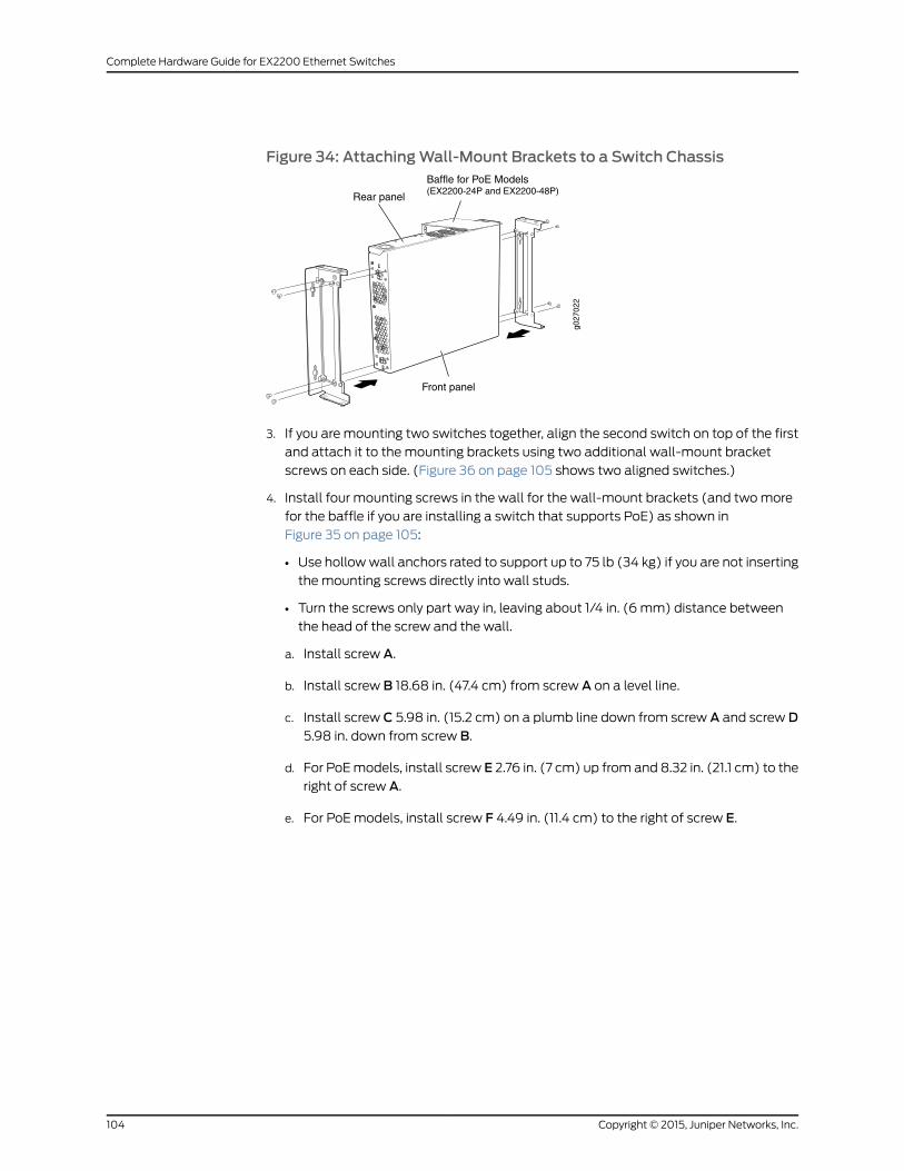
Figure 34: AttachingWall-Mount Brackets to a Switch Chassis
g027
022
Front panel
Rear panel
Baffle for PoE Models(EX2200-24P and EX2200-48P)
3. If you are mounting two switches together, align the second switch on top of the first
and attach it to the mounting brackets using two additional wall-mount bracket
screws on each side. (Figure 36 on page 105 shows two aligned switches.)
4. Install four mounting screws in the wall for the wall-mount brackets (and twomore
for the baffle if you are installing a switch that supports PoE) as shown in
Figure 35 on page 105:
• Use hollowwall anchors rated to support up to 75 lb (34 kg) if you are not inserting
the mounting screws directly into wall studs.
• Turn the screws only part way in, leaving about 1/4 in. (6 mm) distance between
the head of the screw and the wall.
a. Install screw A.
b. Install screw B 18.68 in. (47.4 cm) from screw A on a level line.
c. Install screw C 5.98 in. (15.2 cm) on a plumb line down from screw A and screw D5.98 in. down from screw B.
d. For PoEmodels, install screw E 2.76 in. (7 cm) up from and 8.32 in. (21.1 cm) to the
right of screw A.
e. For PoEmodels, install screw F 4.49 in. (11.4 cm) to the right of screw E.
Copyright © 2015, Juniper Networks, Inc.104
Complete Hardware Guide for EX2200 Ethernet Switches
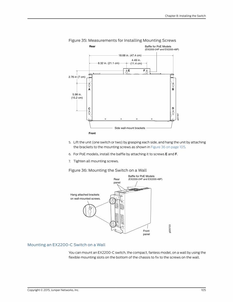
Figure 35: Measurements for Installing Mounting Screws
18.68 in. (47.4 cm)
Front
Rear
A
E F
C
B
D
Side wall-mount brackets
8.32 in. (21.1 cm)4.49 in.
(11.4 cm)
5.98 in.(15.2 cm)
2.76 in (7 cm)
g021
067
Baffle for PoE Models(EX2200-24P and EX2200-48P)
5. Lift the unit (one switch or two) by grasping each side, and hang the unit by attaching
the brackets to the mounting screws as shown in Figure 36 on page 105.
6. For PoEmodels, install the baffle by attaching it to screws E and F.
7. Tighten all mounting screws.
Figure 36: Mounting the Switch on aWallg0
2072
3
Hang attached brackets
on wall-mounted screws.
Frontpanel
Rearpanel
Baffle for PoE Models(EX2200-24P and EX2200-48P)
Mounting an EX2200-C Switch on aWall
You canmount an EX2200-C switch, the compact, fanlessmodel, on awall by using the
flexible mounting slots on the bottom of the chassis to fix to the screws on the wall.
105Copyright © 2015, Juniper Networks, Inc.
Chapter 8: Installing the Switch
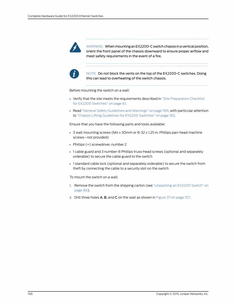
WARNING: WhenmountinganEX2200-Cswitchchassis inaverticalposition,orient the front panel of the chassis downward to ensure proper airflow andmeet safety requirements in the event of a fire.
NOTE: Do not block the vents on the top of the EX2200-C switches. Doingthis can lead to overheating of the switch chassis.
Before mounting the switch on a wall:
• Verify that the site meets the requirements described in “Site Preparation Checklist
for EX2200 Switches” on page 61.
• Read “General Safety Guidelines andWarnings” on page 169, with particular attention
to “Chassis Lifting Guidelines for EX2200 Switches” on page 183.
Ensure that you have the following parts and tools available:
• 3 wall mounting screws (M4 x 30mm or 8-32 x 1.25 in. Phillips pan-headmachine
screws—not provided)
• Phillips (+) screwdriver, number 2
• 1 cable guard and 3 number-8 Phillips truss-head screws (optional and separately
orderable) to secure the cable guard to the switch
• 1 standard cable lock (optional and separately orderable) to secure the switch from
theft by connecting the cable to a security slot on the switch
Tomount the switch on a wall:
1. Remove the switch from the shipping carton (see “Unpacking an EX2200 Switch” on
page 86).
2. Drill three holes A, B, and C on the wall as shown in Figure 37 on page 107.
Copyright © 2015, Juniper Networks, Inc.106
Complete Hardware Guide for EX2200 Ethernet Switches
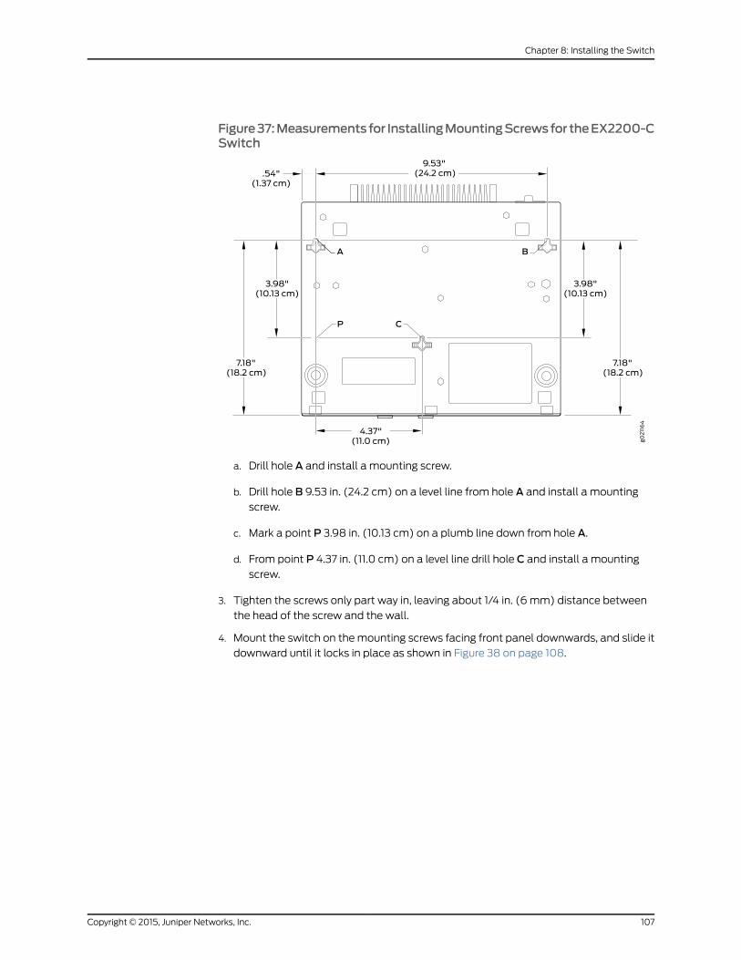
Figure37:Measurementsfor InstallingMountingScrewsfor theEX2200-CSwitch
a. Drill hole A and install a mounting screw.
b. Drill hole B 9.53 in. (24.2 cm) on a level line from hole A and install a mountingscrew.
c. Mark a point P 3.98 in. (10.13 cm) on a plumb line down from hole A.
d. From point P 4.37 in. (11.0 cm) on a level line drill hole C and install a mountingscrew.
3. Tighten the screws only part way in, leaving about 1/4 in. (6 mm) distance between
the head of the screw and the wall.
4. Mount the switch on themounting screws facing front panel downwards, and slide it
downward until it locks in place as shown in Figure 38 on page 108.
107Copyright © 2015, Juniper Networks, Inc.
Chapter 8: Installing the Switch
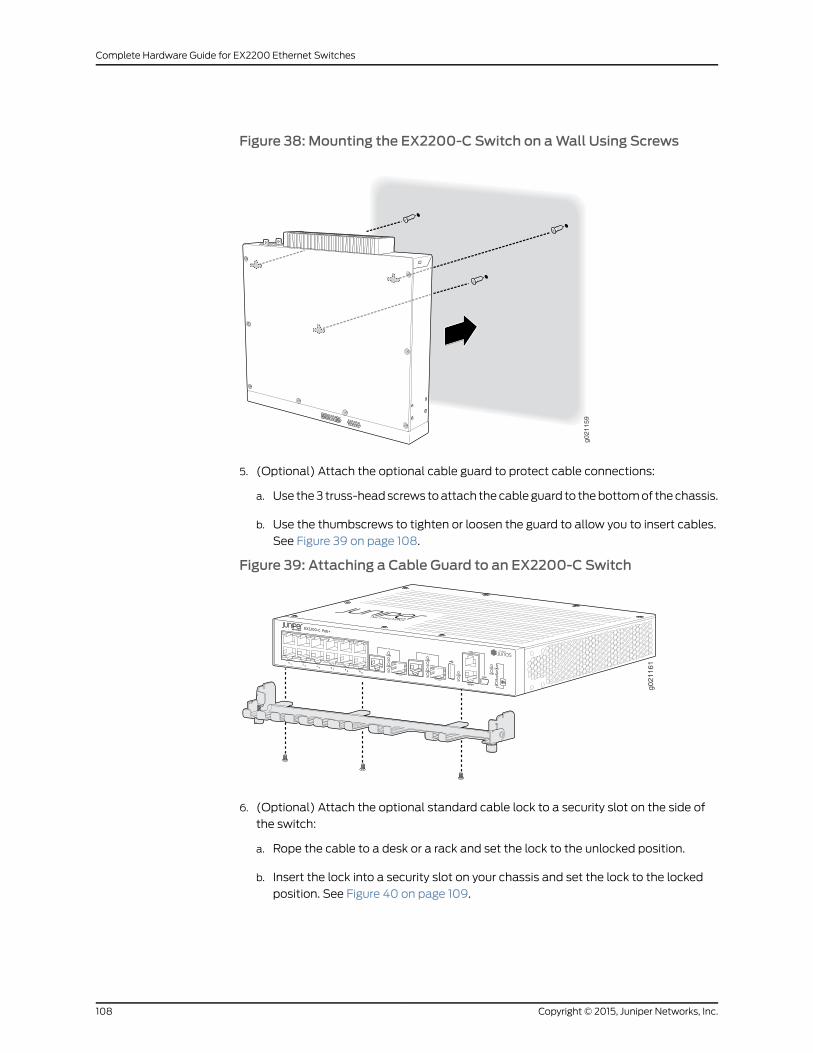
Figure 38: Mounting the EX2200-C Switch on aWall Using Screws
g0
21
15
9
5. (Optional) Attach the optional cable guard to protect cable connections:
a. Use the3 truss-headscrews toattach thecableguard to thebottomof thechassis.
b. Use the thumbscrews to tighten or loosen the guard to allow you to insert cables.
See Figure 39 on page 108.
Figure 39: Attaching a Cable Guard to an EX2200-C Switch
g021161
6. (Optional) Attach the optional standard cable lock to a security slot on the side of
the switch:
a. Rope the cable to a desk or a rack and set the lock to the unlocked position.
b. Insert the lock into a security slot on your chassis and set the lock to the locked
position. See Figure 40 on page 109.
Copyright © 2015, Juniper Networks, Inc.108
Complete Hardware Guide for EX2200 Ethernet Switches
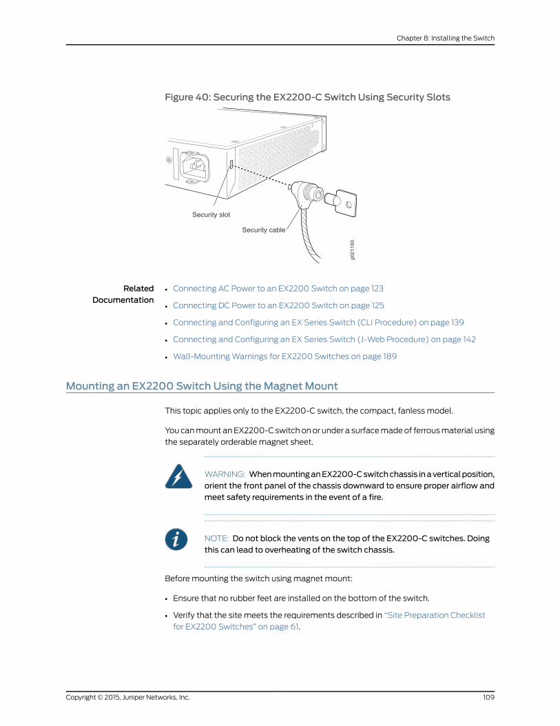
Figure 40: Securing the EX2200-C Switch Using Security Slots
g021160
Security slot
Security cable
RelatedDocumentation
Connecting AC Power to an EX2200 Switch on page 123•
• Connecting DC Power to an EX2200 Switch on page 125
• Connecting and Configuring an EX Series Switch (CLI Procedure) on page 139
• Connecting and Configuring an EX Series Switch (J-Web Procedure) on page 142
• Wall-MountingWarnings for EX2200 Switches on page 189
Mounting an EX2200 Switch Using theMagnet Mount
This topic applies only to the EX2200-C switch, the compact, fanless model.
You canmount anEX2200-C switchonor under a surfacemadeof ferrousmaterial using
the separately orderable magnet sheet.
WARNING: WhenmountinganEX2200-Cswitchchassis inaverticalposition,orient the front panel of the chassis downward to ensure proper airflow andmeet safety requirements in the event of a fire.
NOTE: Do not block the vents on the top of the EX2200-C switches. Doingthis can lead to overheating of the switch chassis.
Before mounting the switch using magnet mount:
• Ensure that no rubber feet are installed on the bottom of the switch.
• Verify that the site meets the requirements described in “Site Preparation Checklist
for EX2200 Switches” on page 61.
109Copyright © 2015, Juniper Networks, Inc.
Chapter 8: Installing the Switch

• Place the desk in its permanent location, allowing adequate clearance for airflow and
maintenance, and secure it to the building structure.
• Read “General Safety Guidelines andWarnings” on page 169, with particular attention
to “Chassis Lifting Guidelines for EX2200 Switches” on page 183.
• Remove the switch from the shipping carton (see “Unpacking an EX2200 Switch” on
page 86).
Ensure that you have the following parts and tools available:
• Magnet sheet (separately orderable)
• Flat surface made of ferrous material
• 1 cable guard and 3 number-8 Phillips truss-head screws (optional and separately
orderable) to secure the cable guard to the switch
• 1 standard cable lock (optional and separately orderable) to secure the switch from
theft by connecting the cable to the security slots on the switch
1. Mount the switch under a ferrous surface using magnet mount:
a. Turn the chassis upside down.
b. Place the magnet sheet on the bottom of the chassis.
NOTE: You can place themagnet sheet only at the bottom of theswitch.
c. Mount themagnet sheet along with the switch under the surface where you want
to mount the switch.
2. Mount the switch vertically on a ferrous surface using magnet mount:
a. Place the magnet sheet at the bottom of the chassis.
NOTE: You can place themagnet sheet only at the bottom of theswitch.
b. Mount the magnet along with the switch on the ferrous surface where you want
to mount the switch orienting the front panel downwards as shown in
Figure 41 on page 111.
Copyright © 2015, Juniper Networks, Inc.110
Complete Hardware Guide for EX2200 Ethernet Switches
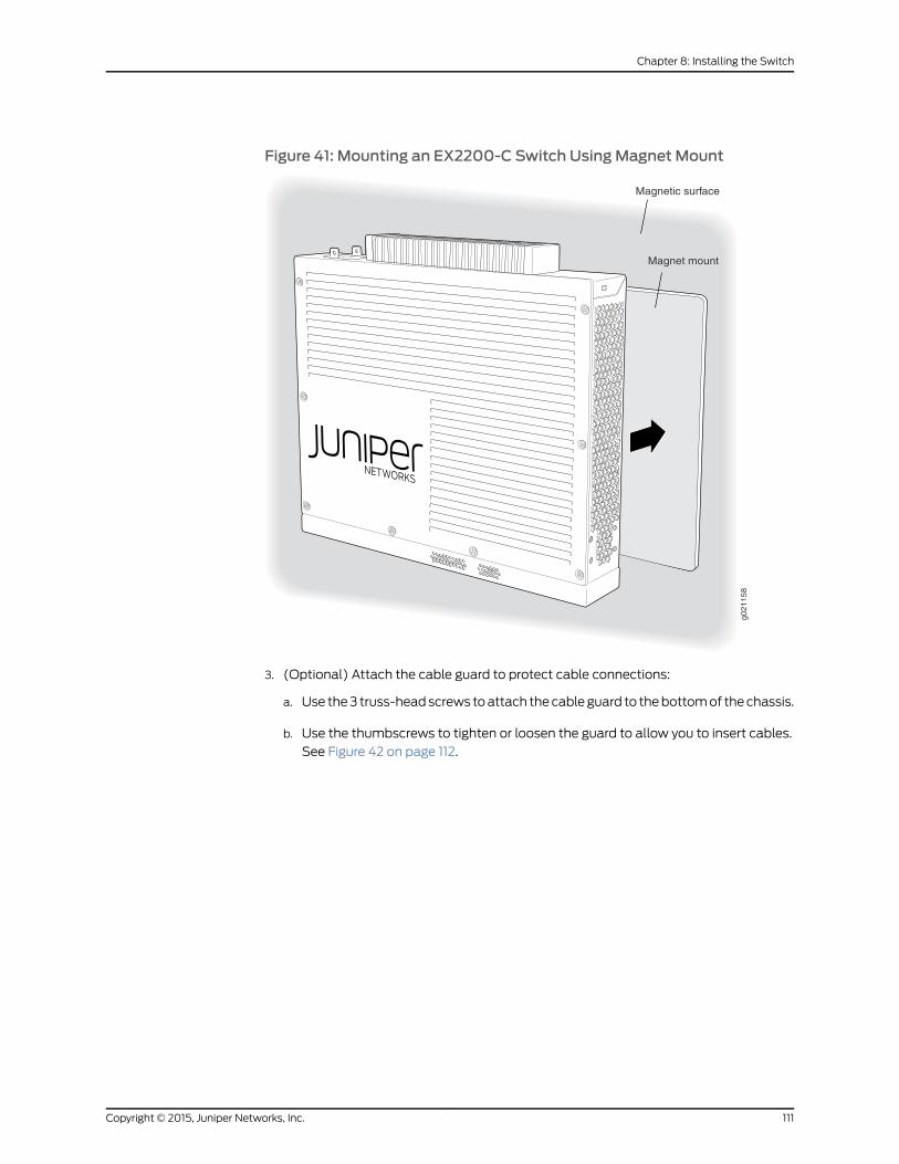
Figure 41: Mounting an EX2200-C Switch UsingMagnet Mount
g021158
Magnet mount
Magnetic surface
3. (Optional) Attach the cable guard to protect cable connections:
a. Use the3 truss-headscrews toattach thecableguard to thebottomof thechassis.
b. Use the thumbscrews to tighten or loosen the guard to allow you to insert cables.
See Figure 42 on page 112.
111Copyright © 2015, Juniper Networks, Inc.
Chapter 8: Installing the Switch

Figure 42: Attaching a Cable Guard to an EX2200-C Switch
g021161
4. (Optional) Attach the standard cable lock to the security slots on the both sides of
the switch
a. Rope the cable to a desk or a rack and set the lock to unlocked position.
b. Insert the lock into one of the security slot on your chassis and set the lock to the
locked position. See Figure 43 on page 112.
Figure 43: Securing the EX2200-C Switch Using Security Slotsg021160
Security slot
Security cable
RelatedDocumentation
• Connecting AC Power to an EX2200 Switch on page 123
• Connecting and Configuring an EX Series Switch (CLI Procedure) on page 139
• Wall-MountingWarnings for EX2200 Switches on page 189
Copyright © 2015, Juniper Networks, Inc.112
Complete Hardware Guide for EX2200 Ethernet Switches
CHAPTER 9
Installing Switch Components
• Installing a Transceiver in an EX Series Switch on page 113
Installing a Transceiver in an EX Series Switch
The transceivers for EX Series switches are hot-removable and hot-insertable
field-replaceable units (FRUs): You can remove and replace themwithout powering off
the switch or disrupting switch functions.
NOTE: After you insert a transceiver or after you change themedia-typeconfiguration, wait for 6 seconds for the interface to display operationalcommands.
NOTE: We recommend that you use only optical transceivers and opticalconnectors purchased from Juniper Networks with your Juniper Networksdevice.
CAUTION: If you are having a problem running a Juniper Networks devicethat is using a third-party optic or cable, the Juniper Networks TechnicalAssistance Center (JTAC) can help you diagnose the source of the problem.Your JTAC engineer might recommend that you check the third-party opticor cable and potentially replace it with an equivalent Juniper Networks opticor cable that is qualified for the device.
NOTE: OnanEX3200switch, if you install a transceiver ina 1-GigabitEthernetuplink module port, a corresponding network port from the last four built-inports is disabled. For example, if you install a transceiver in theuplinkmoduleport 3 (ge-0/1/2), then the built-in port 23 (ge-0/0/22) is disabled. The
disabled port is not listed in the output of show interface commands.
113Copyright © 2015, Juniper Networks, Inc.
Before you begin installing a transceiver in an EX Series switch, ensure that you have
taken the necessary precautions for safe handling of lasers (see “Laser and LED Safety
Guidelines andWarnings for Switches” on page 175).
Ensure that you have a rubber safety cap available to cover the transceiver.
Figure 44 on page 115 shows how to install a QSFP+ transceiver. The procedure is the
same for all types of transceivers.
To install a transceiver in an EX Series switch:
CAUTION: To prevent electrostatic discharge (ESD) damage to thetransceiver, do not touch the connector pins at the end of the transceiver.
1. Remove the transceiver from its bag.
2. Check to see whether the transceiver is covered with a rubber safety cap. If it is not,
cover the transceiver with a rubber safety cap.
WARNING: Do not leave a fiber-optic transceiver uncovered exceptwheninserting or removing a cable. The rubber safety cap keeps the port cleanand prevents accidental exposure to laser light.
3. If the port in which you want to install the transceiver is covered with a dust cover,
remove the dust cover and save it in case you need to cover the port later. If you are
hot-swappinga transceiver,wait for at least 10 secondsafter removing the transceiver
from the port before installing a new transceiver.
4. Using both hands, carefully place the transceiver in the empty port. The connectors
must face the switch chassis.
CAUTION: Before you slide the transceiver into the port, ensure that thetransceiver is aligned correctly. Misalignmentmight cause the pins tobend, making the transceiver unusable.
5. Slide the transceiver in gently until it is fully seated. If you are installing a CFP
transceiver, tighten the captive screws on the transceiver by using your fingers.
6. Remove the rubber safety cap when you are ready to connect the cable to the
transceiver.
WARNING: Do not look directly into a fiber-optic transceiver or into theends of fiber-optic cables. Fiber-optic transceivers and fiber-optic cablesconnected to transceivers emit laser light that can damage your eyes.
Copyright © 2015, Juniper Networks, Inc.114
Complete Hardware Guide for EX2200 Ethernet Switches
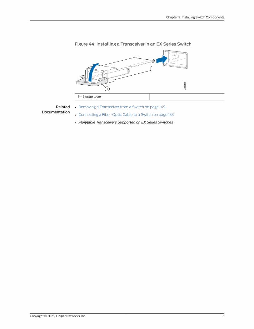
Figure 44: Installing a Transceiver in an EX Series Switch
1—Ejector lever
RelatedDocumentation
• Removing a Transceiver from a Switch on page 149
• Connecting a Fiber-Optic Cable to a Switch on page 133
• Pluggable Transceivers Supported on EX Series Switches
115Copyright © 2015, Juniper Networks, Inc.
Chapter 9: Installing Switch Components

Copyright © 2015, Juniper Networks, Inc.116
Complete Hardware Guide for EX2200 Ethernet Switches
CHAPTER 10
Connecting the Switch
• Connecting Earth Ground to an EX Series Switch on page 117
• Connecting AC Power to an EX2200 Switch on page 123
• Connecting DC Power to an EX2200 Switch on page 125
• Connecting a Switch to a Network for Out-of-Band Management on page 127
• Connecting a Switch to a Management Console on page 129
• Connecting an EX2200 Switch to a Management Console Using Mini-USB Type-B
Console Port on page 131
• Connecting a Fiber-Optic Cable to a Switch on page 133
Connecting Earth Ground to an EX Series Switch
To ensure proper operation and to meet safety and electromagnetic interference (EMI)
requirements, youmust connect an EX Series switch to earth ground before you connect
power to the switch. Youmust use the protective earthing terminal on the switch chassis
to connect the switch to earth ground (see Figure 46 on page 122).
WARNING: The switch is installed in a restricted-access location. It has aseparateprotectiveearthingterminalonthechassis thatmustbepermanentlyconnected to earth ground to adequately ground the chassis and protect theoperator from electrical hazards.
CAUTION: Beforeswitch installationbegins, ensure thata licensedelectricianhas attached an appropriate grounding lug to the grounding cable that yousupply. Using a grounding cablewith an incorrectly attached lug candamagethe switch.
This topic describes:
• Parts and Tools Required for Connecting an EX Series Switch to Earth
Ground on page 118
• Special Instructions toFollowBeforeConnectingEarthGround toaSwitchonpage 120
• Connecting Earth Ground to an EX Series Switch on page 122
117Copyright © 2015, Juniper Networks, Inc.
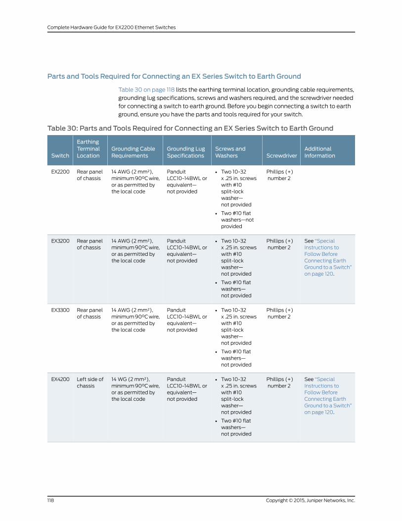
Parts and Tools Required for Connecting an EX Series Switch to Earth Ground
Table 30 on page 118 lists the earthing terminal location, grounding cable requirements,
grounding lug specifications, screws and washers required, and the screwdriver needed
for connecting a switch to earth ground. Before you begin connecting a switch to earth
ground, ensure you have the parts and tools required for your switch.
Table 30: Parts and Tools Required for Connecting an EX Series Switch to Earth Ground
AdditionalInformationScrewdriver
Screws andWashers
Grounding LugSpecifications
Grounding CableRequirements
EarthingTerminalLocationSwitch
Phillips (+)number 2
• Two 10-32x .25 in. screwswith #10split-lockwasher—not provided
• Two #10 flatwashers—notprovided
PanduitLCC10-14BWL orequivalent—not provided
14 AWG (2mm²),minimum90°Cwire,or as permitted bythe local code
Rear panelof chassis
EX2200
See “SpecialInstructions toFollow BeforeConnecting EarthGround to a Switch”on page 120.
Phillips (+)number 2
• Two 10-32x .25 in. screwswith #10split-lockwasher—not provided
• Two #10 flatwashers—not provided
PanduitLCC10-14BWL orequivalent—not provided
14 AWG (2mm²),minimum90°Cwire,or as permitted bythe local code
Rear panelof chassis
EX3200
Phillips (+)number 2
• Two 10-32x .25 in. screwswith #10split-lockwasher—not provided
• Two #10 flatwashers—not provided
PanduitLCC10-14BWL orequivalent—not provided
14 AWG (2mm²),minimum90°Cwire,or as permitted bythe local code
Rear panelof chassis
EX3300
See “SpecialInstructions toFollow BeforeConnecting EarthGround to a Switch”on page 120.
Phillips (+)number 2
• Two 10-32x .25 in. screwswith #10split-lockwasher—not provided
• Two #10 flatwashers—not provided
PanduitLCC10-14BWL orequivalent—not provided
14WG (2mm²),minimum90°Cwire,or as permitted bythe local code
Left side ofchassis
EX4200
Copyright © 2015, Juniper Networks, Inc.118
Complete Hardware Guide for EX2200 Ethernet Switches
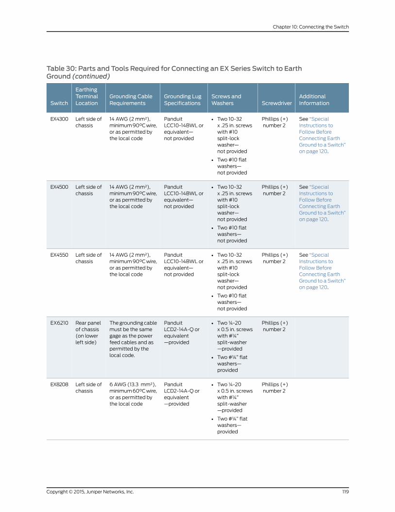
Table 30: Parts and Tools Required for Connecting an EX Series Switch to EarthGround (continued)
AdditionalInformationScrewdriver
Screws andWashers
Grounding LugSpecifications
Grounding CableRequirements
EarthingTerminalLocationSwitch
See “SpecialInstructions toFollow BeforeConnecting EarthGround to a Switch”on page 120.
Phillips (+)number 2
• Two 10-32x .25 in. screwswith #10split-lockwasher—not provided
• Two #10 flatwashers—not provided
PanduitLCC10-14BWL orequivalent—not provided
14 AWG (2mm²),minimum90°Cwire,or as permitted bythe local code
Left side ofchassis
EX4300
See “SpecialInstructions toFollow BeforeConnecting EarthGround to a Switch”on page 120.
Phillips (+)number 2
• Two 10-32x .25 in. screwswith #10split-lockwasher—not provided
• Two #10 flatwashers—not provided
PanduitLCC10-14BWL orequivalent—not provided
14 AWG (2mm²),minimum90°Cwire,or as permitted bythe local code
Left side ofchassis
EX4500
See “SpecialInstructions toFollow BeforeConnecting EarthGround to a Switch”on page 120.
Phillips (+)number 2
• Two 10-32x .25 in. screwswith #10split-lockwasher—not provided
• Two #10 flatwashers—not provided
PanduitLCC10-14BWL orequivalent—not provided
14 AWG (2mm²),minimum90°Cwire,or as permitted bythe local code
Left side ofchassis
EX4550
Phillips (+)number 2
• Two¼-20x 0.5 in. screwswith #¼”split-washer—provided
• Two #¼” flatwashers—provided
PanduitLCD2-14A-Q orequivalent—provided
Thegroundingcablemust be the samegage as the powerfeed cables and aspermitted by thelocal code.
Rear panelof chassis(on lowerleft side)
EX6210
Phillips (+)number 2
• Two¼-20x 0.5 in. screwswith #¼”split-washer—provided
• Two #¼” flatwashers—provided
PanduitLCD2-14A-Q orequivalent—provided
6 AWG (13.3 mm²),minimum60°Cwire,or as permitted bythe local code
Left side ofchassis
EX8208
119Copyright © 2015, Juniper Networks, Inc.
Chapter 10: Connecting the Switch
Table 30: Parts and Tools Required for Connecting an EX Series Switch to EarthGround (continued)
AdditionalInformationScrewdriver
Screws andWashers
Grounding LugSpecifications
Grounding CableRequirements
EarthingTerminalLocationSwitch
See “SpecialInstructions toFollow BeforeConnecting EarthGround to a Switch”on page 120.
Phillips (+)number 2
• Two¼-20 x0.5 in. screwswith #¼”split-washer—provided
• Two #¼” flatwashers—provided
PanduitLCD2-14A-Q orequivalent—provided
2 AWG(33.6 mm²),minimum60°Cwire,or as permitted bythe local code
Twoearthingterminals:
• Left sideofchassis
• Rearpanel ofchassis
EX8216
See GroundingCable and LugSpecifications forEX9200 Switches.
Phillips (+)number 2
• Two¼-20x 0.5 in. screwswith #¼”split-washer—provided
• Two #¼” flatwashers—provided
Thomas&BettsLCN6-14 orequivalent—provided
One 6 AWG (13.3mm²), minimum60°C wire, or onethat complies withthe local code
Rear panelof chassis
EX9204
See GroundingCable and LugSpecifications forEX9200 Switches.
Phillips (+)number 2
• Two¼-20x 0.5 in. screwswith #¼”split-washer—provided
• Two #¼” flatwashers—provided
Thomas&BettsLCN6-14 orequivalent—provided
One 6 AWG (13.3mm²), minimum60°C wire, or onethat complies withthe local code
Rear panelof chassis
EX9208
See GroundingCable and LugSpecifications forEX9200 Switches.
Phillips (+)number 2
• Two¼-20x 0.5 in. screwswith #¼”split-washer—provided
• Two #¼” flatwashers—provided
Thomas&BettsLCN6-14 orequivalent—provided
One 6 AWG (13.3mm²), minimum60°C wire, or onethat complies withthe local code
Rear panelof chassis
EX9214
Special Instructions to Follow Before Connecting Earth Ground to a Switch
Table 31 on page 120 lists the special instructions that youmight need to follow before
connecting earth ground to a switch.
Table 31: Special Instructions to Follow Before Connecting Earth Ground to a Switch
Special InstructionsSwitch
NOTE: Someearly variants of EX3200 switches forwhich the Juniper Networksmodel number on the labelnext to theprotective earthing terminal is from750-021xxx through750-030xxx require 10-24x.25 in. screws.
EX3200
Copyright © 2015, Juniper Networks, Inc.120
Complete Hardware Guide for EX2200 Ethernet Switches
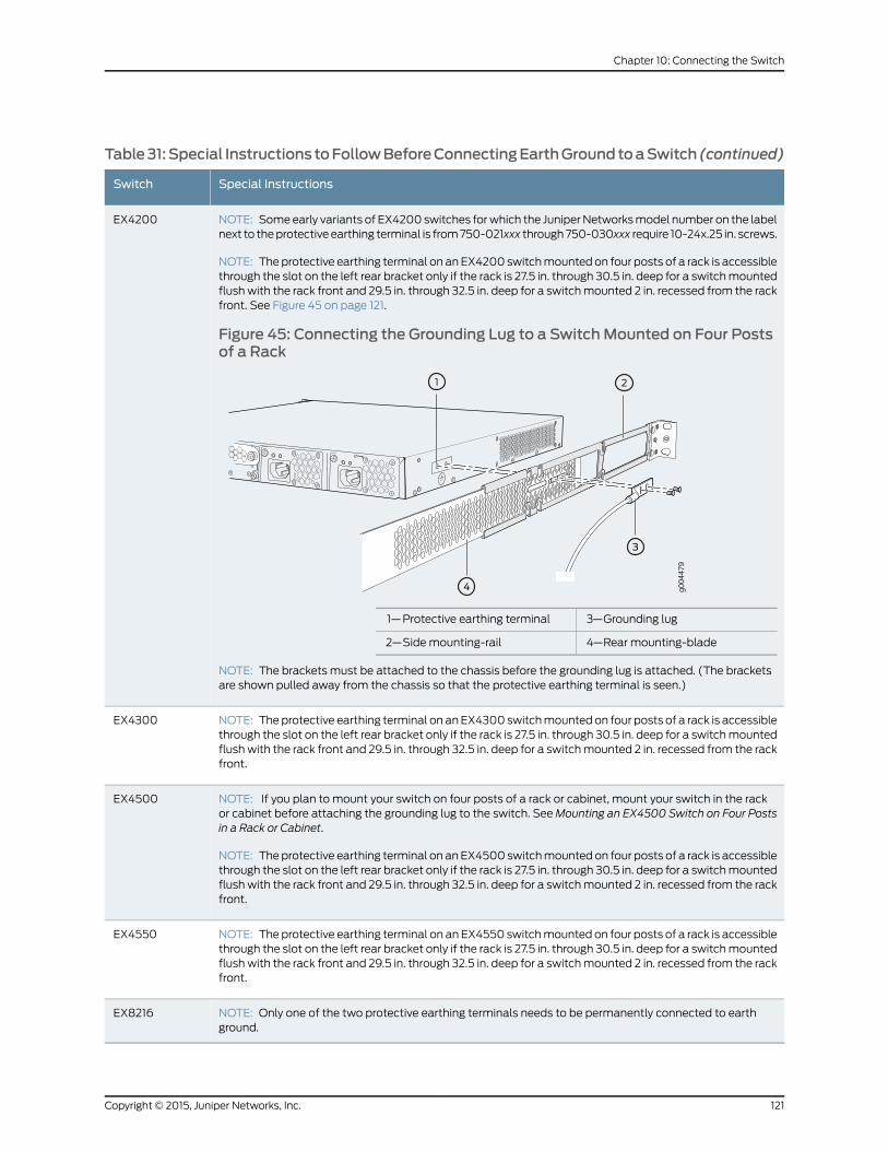
Table31:Special Instructions toFollowBeforeConnectingEarthGroundtoaSwitch (continued)
Special InstructionsSwitch
NOTE: Someearly variants of EX4200 switches forwhich the JuniperNetworksmodel number on the labelnext to theprotective earthing terminal is from750-021xxx through750-030xxx require 10-24x.25 in. screws.
NOTE: The protective earthing terminal on an EX4200 switchmounted on four posts of a rack is accessiblethrough the slot on the left rear bracket only if the rack is 27.5 in. through 30.5 in. deep for a switchmountedflushwith the rack front and 29.5 in. through 32.5 in. deep for a switchmounted 2 in. recessed from the rackfront. See Figure 45 on page 121.
Figure 45: Connecting the Grounding Lug to a SwitchMounted on Four Postsof a Rack
g004
479
3—1— Grounding lugProtective earthing terminal
4—2— Rear mounting-bladeSide mounting-rail
NOTE: The brackets must be attached to the chassis before the grounding lug is attached. (The bracketsare shown pulled away from the chassis so that the protective earthing terminal is seen.)
EX4200
NOTE: The protective earthing terminal on anEX4300 switchmounted on four posts of a rack is accessiblethrough the slot on the left rear bracket only if the rack is 27.5 in. through 30.5 in. deep for a switchmountedflushwith the rack front and 29.5 in. through 32.5 in. deep for a switchmounted 2 in. recessed from the rackfront.
EX4300
NOTE: If you plan to mount your switch on four posts of a rack or cabinet, mount your switch in the rackor cabinet before attaching the grounding lug to the switch. SeeMounting an EX4500 Switch on Four Postsin a Rack or Cabinet.
NOTE: Theprotective earthing terminal on anEX4500 switchmountedon four posts of a rack is accessiblethrough the slot on the left rear bracket only if the rack is 27.5 in. through 30.5 in. deep for a switchmountedflushwith the rack front and 29.5 in. through 32.5 in. deep for a switchmounted 2 in. recessed from the rackfront.
EX4500
NOTE: The protective earthing terminal on an EX4550 switchmounted on four posts of a rack is accessiblethrough the slot on the left rear bracket only if the rack is 27.5 in. through 30.5 in. deep for a switchmountedflushwith the rack front and 29.5 in. through 32.5 in. deep for a switchmounted 2 in. recessed from the rackfront.
EX4550
NOTE: Only one of the two protective earthing terminals needs to be permanently connected to earthground.
EX8216
121Copyright © 2015, Juniper Networks, Inc.
Chapter 10: Connecting the Switch
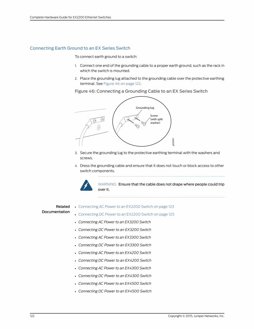
Connecting Earth Ground to an EX Series Switch
To connect earth ground to a switch:
1. Connect one end of the grounding cable to a proper earth ground, such as the rack in
which the switch is mounted.
2. Place the grounding lug attached to the grounding cable over the protective earthing
terminal. See Figure 46 on page 122.
Figure 46: Connecting a Grounding Cable to an EX Series Switch
3. Secure the grounding lug to the protective earthing terminal with the washers and
screws.
4. Dress the grounding cable and ensure that it does not touch or block access to other
switch components.
WARNING: Ensure that the cable does not drapewhere people could tripover it.
RelatedDocumentation
Connecting AC Power to an EX2200 Switch on page 123•
• Connecting DC Power to an EX2200 Switch on page 125
• Connecting AC Power to an EX3200 Switch
• Connecting DC Power to an EX3200 Switch
• Connecting AC Power to an EX3300 Switch
• Connecting DC Power to an EX3300 Switch
• Connecting AC Power to an EX4200 Switch
• Connecting DC Power to an EX4200 Switch
• Connecting AC Power to an EX4300 Switch
• Connecting DC Power to an EX4300 Switch
• Connecting AC Power to an EX4500 Switch
• Connecting DC Power to an EX4500 Switch
Copyright © 2015, Juniper Networks, Inc.122
Complete Hardware Guide for EX2200 Ethernet Switches
• Connecting AC Power to an EX4550 Switch
• Connecting DC Power to an EX4550 Switch
• Connecting AC Power to an EX6200 Switch
• Connecting DC Power to an EX6200 Switch
• Connecting AC Power to an EX8200 Switch
• Connecting DC Power to an EX8200 Switch
• Connecting AC Power to an EX9204 Switch
• Connecting DC Power to an EX9204 Switch
• Connecting AC Power to an EX9208 Switch
• Connecting DC Power to an EX9208 Switch
• Connecting AC Power to an EX9214 Switch
• Connecting DC Power to an EX9214 Switch
• General Safety Guidelines andWarnings on page 169
• Grounded EquipmentWarning on page 189
Connecting AC Power to an EX2200 Switch
The power supply in an EX2200 switch is located on the rear panel.
Ensure that you have the following parts and tools available:
• A power cord appropriate for your geographical location
• A power cord retainer clip
Ensure that you have connected the switch chassis to earth ground.
CAUTION: Tomeet safety and electromagnetic interference (EMI)requirementsand toensureproperoperation, youmustconnect theswitchesto earth ground before you connect them to power. For installations thatrequire a separate grounding conductor to the chassis, use the protectiveearthing terminal on the switch chassis to connect to the earth ground. Forinstructions on connecting earth ground, see “Connecting Earth Ground toanEXSeriesSwitch”onpage 117.AnEX2200switchgetsadditionalgroundingwhen you plug the power supply in the switch into a grounded AC poweroutlet by using the AC power cord appropriate for your geographical location(see “AC Power Cord Specifications for EX2200 Switches” on page 80).
123Copyright © 2015, Juniper Networks, Inc.
Chapter 10: Connecting the Switch
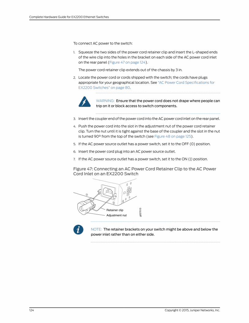
To connect AC power to the switch:
1. Squeeze the two sides of the power cord retainer clip and insert the L-shaped ends
of the wire clip into the holes in the bracket on each side of the AC power cord inlet
on the rear panel (Figure 47 on page 124).
The power cord retainer clip extends out of the chassis by 3 in.
2. Locate the power cord or cords shipped with the switch; the cords have plugs
appropriate for your geographical location. See “AC Power Cord Specifications for
EX2200 Switches” on page 80.
WARNING: Ensure that the power cord does not drapewhere people cantrip on it or block access to switch components.
3. Insert the coupler endof the power cord into theACpower cord inlet on the rear panel.
4. Push the power cord into the slot in the adjustment nut of the power cord retainer
clip. Turn the nut until it is tight against the base of the coupler and the slot in the nut
is turned 90° from the top of the switch (see Figure 48 on page 125).
5. If the AC power source outlet has a power switch, set it to the OFF (0) position.
6. Insert the power cord plug into an AC power source outlet.
7. If the AC power source outlet has a power switch, set it to the ON (|) position.
Figure 47: Connecting an AC Power Cord Retainer Clip to the AC PowerCord Inlet on an EX2200 Switch
g027
013
Retainer clip
Adjustment nut
NOTE: The retainer brackets on your switchmight be above and below thepower inlet rather than on either side.
Copyright © 2015, Juniper Networks, Inc.124
Complete Hardware Guide for EX2200 Ethernet Switches
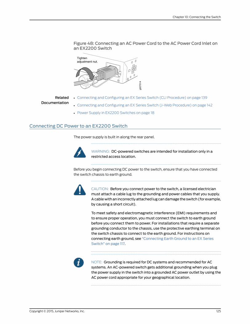
Figure 48: Connecting an AC Power Cord to the AC Power Cord Inlet onan EX2200 Switch
g027
014
Tightenadjustment nut.
RelatedDocumentation
Connecting and Configuring an EX Series Switch (CLI Procedure) on page 139•
• Connecting and Configuring an EX Series Switch (J-Web Procedure) on page 142
• Power Supply in EX2200 Switches on page 18
Connecting DC Power to an EX2200 Switch
The power supply is built in along the rear panel.
WARNING: DC-powered switches are intended for installation only in arestricted access location.
Before you begin connecting DC power to the switch, ensure that you have connected
the switch chassis to earth ground.
CAUTION: Before you connect power to the switch, a licensed electricianmust attach a cable lug to the grounding and power cables that you supply.Acablewithan incorrectlyattached lugcandamage theswitch (for example,by causing a short circuit).
Tomeet safety and electromagnetic interference (EMI) requirements andto ensure proper operation, youmust connect the switch to earth groundbefore you connect them to power. For installations that require a separategrounding conductor to the chassis, use the protective earthing terminal onthe switch chassis to connect to the earth ground. For instructions onconnecting earth ground, see “Connecting Earth Ground to an EX SeriesSwitch” on page 117.
NOTE: Grounding is required for DC systems and recommended for ACsystems. An AC-powered switch gets additional grounding when you plugthe power supply in the switch into a grounded AC power outlet by using theAC power cord appropriate for your geographical location.
125Copyright © 2015, Juniper Networks, Inc.
Chapter 10: Connecting the Switch
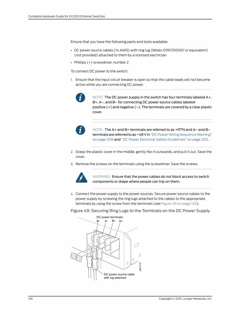
Ensure that you have the following parts and tools available:
• DC power source cables (14 AWG) with ring lug (Molex 0190700067 or equivalent)
(not provided) attached to them by a licensed electrician
• Phillips (+) screwdriver, number 2
To connect DC power to the switch:
1. Ensure that the input circuit breaker is open so that the cable leads will not become
active while you are connecting DC power.
NOTE: The DC power supply in the switch has four terminals labeled A+,B+, A–, and B– for connecting DC power source cables labeledpositive (+) and negative (–). The terminals are covered by a clear plasticcover.
NOTE: The A+ and B+ terminals are referred to as +RTN and A– and B–terminalsare referred toas–48V in “DCPowerWiringSequenceWarning”on page 208 and “DC Power Electrical Safety Guidelines” on page 203.
2. Grasp the plastic cover in the middle, gently flex it outwards, and pull it out. Save the
cover.
3. Remove the screws on the terminals using the screwdriver. Save the screws.
WARNING: Ensure that the power cables do not block access to switchcomponents or drape where people can trip on them.
4. Connect the power supply to the power sources. Secure power source cables to the
power supply by screwing the ring lugs attached to the cables to the appropriate
terminals by using the screw from the terminals (see Figure 49 on page 126).
Figure 49: Securing Ring Lugs to the Terminals on the DC Power Supply
g021215
A-
DC power source cablewith lug attached
B- B+ A+DC power terminals:
Copyright © 2015, Juniper Networks, Inc.126
Complete Hardware Guide for EX2200 Ethernet Switches

• To connect the power supply to a power source:
a. Secure the ring lug of the positive (+) DC power source cable to the A+ or B+
terminal on the DC power supply.
b. Secure the ring lug of the negative (–) DC power source cable to the A– or B–
terminal on the DC power supply.
c. Tighten thescrewson thepower supply terminalsuntil snugusing thescrewdriver.
Do not overtighten—apply between 8 in.-lb (0.9 Nm) and 9 in.-lb (1.02 Nm) of
torque to the screws.
• To connect the power supply to two power sources:
a. Secure the ring lug of the positive (+) DC power source cable from the first DC
power source to the A+ terminal on the power supply.
b. Secure the ring lug of the negative (–) DC power source cable from the first DC
power source to the A– terminal on the power supply.
c. Secure the ring lug of the positive (+) DC power source cable from the second
DC power source to the B+ terminal on the power supply.
d. Secure the ring lug of the negative (–) DC power source cable from the second
DC power source to the B– terminal on the power supply.
e. Tighten the screws on the power supply terminals on both the power supplies
until snug using the screwdriver. Do not overtighten—apply between 8 in.-lb
(0.9 Nm) and 9 in.-lb (1.02 Nm) of torque to the screws.
5. Hook the plastic cover on one side of the terminal block and gently flex it inwards to
hook it on the other side also.
6. Close the input circuit breaker.
RelatedDocumentation
Connecting and Configuring an EX Series Switch (CLI Procedure) on page 139•
• Connecting and Configuring an EX Series Switch (J-Web Procedure) on page 142
• Power Supply in EX2200 Switches on page 18
Connecting a Switch to a Network for Out-of-BandManagement
This topic applies to multiple hardware devices in the EX Series product family, which
includes EX Series switches and the XRE200 External Routing Engine.
This topic also applies to OCX1100 switches.
You canmonitor andmanage these devices by using a dedicatedmanagement channel.
Each device has amanagement port with an RJ-45 connector for out-of-band
management.Use themanagementport toconnect theswitchorexternalRoutingEngine
to the management device.
127Copyright © 2015, Juniper Networks, Inc.
Chapter 10: Connecting the Switch

Ensure that you have an Ethernet cable with an RJ-45 connector available. One such
cable is provided with the device. Figure 50 on page 128 shows the RJ-45 connector of
the Ethernet cable supplied with the device.
Figure 50: Ethernet Cable Connector
Toconnectadevice toanetwork forout-of-bandmanagement(seeFigure51onpage 129):
1. Connect one end of the Ethernet cable to the management port (labeledMGMT or
ETHERNET) on the device.
For the location of theMGMT or ETHERNET port on different devices:
• See “EX2200 Switches Hardware Overview” on page 3.
• See Rear Panel of an EX3200 Switch.
• See Rear Panel of an EX3300 Switch.
• See Rear Panel of an EX4200 Switch.
• See EX4300 Switches Hardware Overview
• See Front Panel of an EX4500 Switch.
• See EX4550 Switches Hardware Overview
• See Switch Fabric and Routing Engine (SRE) Module in an EX6200 Switch.
• See Switch Fabric and Routing Engine (SRE) Module in an EX8208 Switch.
• See Routing Engine (RE) Module in an EX8216 Switch.
• See Front Panel of an XRE200 External Routing Engine.
• SeeOCX1100 Switches Hardware Overview.
2. Connect the other end of the Ethernet cable to the management device.
Copyright © 2015, Juniper Networks, Inc.128
Complete Hardware Guide for EX2200 Ethernet Switches
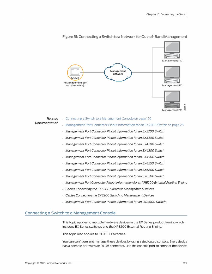
Figure51:ConnectingaSwitchtoaNetworkforOut-of-BandManagement
RelatedDocumentation
Connecting a Switch to a Management Console on page 129•
• Management Port Connector Pinout Information for an EX2200 Switch on page 25
• Management Port Connector Pinout Information for an EX3200 Switch
• Management Port Connector Pinout Information for an EX3300 Switch
• Management Port Connector Pinout Information for an EX4200 Switch
• Management Port Connector Pinout Information for an EX4300 Switch
• Management Port Connector Pinout Information for an EX4500 Switch
• Management Port Connector Pinout Information for an EX4550 Switch
• Management Port Connector Pinout Information for an EX6200 Switch
• Management Port Connector Pinout Information for an EX8200 Switch
• Management Port Connector Pinout Information for an XRE200 External Routing Engine
• Cables Connecting the EX6200 Switch to Management Devices
• Cables Connecting the EX8200 Switch to Management Devices
• Management Port Connector Pinout Information for an OCX1100 Switch
Connecting a Switch to aManagement Console
This topic applies to multiple hardware devices in the EX Series product family, which
includes EX Series switches and the XRE200 External Routing Engine.
This topic also applies to OCX1100 switches.
You can configure andmanage these devices by using a dedicated console. Every device
has a console port with an RJ-45 connector. Use the console port to connect the device
129Copyright © 2015, Juniper Networks, Inc.
Chapter 10: Connecting the Switch
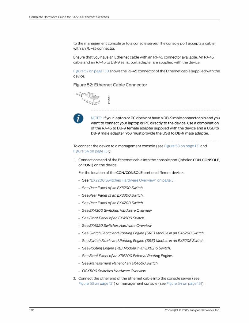
to the management console or to a console server. The console port accepts a cable
with an RJ-45 connector.
Ensure that you have an Ethernet cable with an RJ-45 connector available. An RJ-45
cable and an RJ-45 to DB-9 serial port adapter are supplied with the device.
Figure 52 onpage 130 shows theRJ-45 connector of the Ethernet cable suppliedwith the
device.
Figure 52: Ethernet Cable Connector
NOTE: If your laptopor PCdoes not have aDB-9male connector pin and youwant to connect your laptop or PC directly to the device, use a combinationof the RJ-45 to DB-9 female adapter supplied with the device and a USB toDB-9male adapter. Youmust provide the USB to DB-9male adapter.
To connect the device to amanagement console (see Figure 53 on page 131 and
Figure 54 on page 131):
1. Connect one end of the Ethernet cable into the console port (labeledCON,CONSOLE,
or CON1) on the device.
For the location of the CON/CONSOLE port on different devices:
• See “EX2200 Switches Hardware Overview” on page 3.
• See Rear Panel of an EX3200 Switch.
• See Rear Panel of an EX3300 Switch.
• See Rear Panel of an EX4200 Switch.
• See EX4300 Switches Hardware Overview
• See Front Panel of an EX4500 Switch.
• See EX4550 Switches Hardware Overview
• See Switch Fabric and Routing Engine (SRE) Module in an EX6200 Switch.
• See Switch Fabric and Routing Engine (SRE) Module in an EX8208 Switch.
• See Routing Engine (RE) Module in an EX8216 Switch.
• See Front Panel of an XRE200 External Routing Engine.
• SeeManagement Panel of an EX4600 Switch
• OCX1100 Switches Hardware Overview
2. Connect the other end of the Ethernet cable into the console server (see
Figure 53 on page 131) or management console (see Figure 54 on page 131).
Copyright © 2015, Juniper Networks, Inc.130
Complete Hardware Guide for EX2200 Ethernet Switches
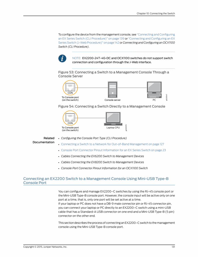
To configure the device from themanagement console, see “Connecting andConfiguring
an EX Series Switch (CLI Procedure)” on page 139 or “Connecting and Configuring an EX
SeriesSwitch (J-WebProcedure)” onpage 142orConnecting andConfiguring anOCX1100
Switch (CLI Procedure).
NOTE: EX2200-24T-4G-DC and OCX1100 switches do not support switchconnection and configuration through the J-Web interface.
Figure 53: Connecting a Switch to aManagement Console Through aConsole Server
Figure 54: Connecting a Switch Directly to aManagement Console
RelatedDocumentation
Configuring the Console Port Type (CLI Procedure)•
• Connecting a Switch to a Network for Out-of-Band Management on page 127
• Console Port Connector Pinout Information for an EX Series Switch on page 23
• Cables Connecting the EX6200 Switch to Management Devices
• Cables Connecting the EX8200 Switch to Management Devices
• Console Port Connector Pinout Information for an OCX1100 Switch
Connecting an EX2200 Switch to aManagement Console UsingMini-USB Type-BConsole Port
You can configure andmanage EX2200–C switches by using the RJ-45 console port or
theMini-USB Type-B console port. However, the console input will be active only on one
port at a time, that is, only one port will be set active at a time.
If your laptop or PC does not have a DB-9male connector pin or RJ-45 connector pin,
you can connect your laptop or PC directly to an EX2200–C switch using amini-USB
cable that has a Standard-A USB connector on one end and a Mini-USB Type-B (5 pin)
connector on the other end.
This sectiondescribes theprocessofconnectinganEX2200–Cswitch to themanagement
console using the Mini-USB Type-B console port.
131Copyright © 2015, Juniper Networks, Inc.
Chapter 10: Connecting the Switch

For information about configuring andmanaging an EX2200–C switch using the RJ-45
console port, see “Connecting a Switch to a Management Console” on page 129.
Before you begin connecting an EX2200–C switch using Mini-USB Type-B console port:
• Ensure that theUSB toSerial driver is installedon thehostmachine. You candownload
thedriver fromhttps://webdownload.juniper.net/swdl/dl/secure/site/1/record/5029.html
.
• Ensure that the hyper terminal properties of the console server or laptop are set as
follows:
• Baud rate—9600
• Flow control—None
• Data—8
• Parity—None
• Stop bits—1
• DCD state—Disregard
Ensure that you have the following parts and tools available:
• 1 mini-USB cable with Standard-A and Mini-USB Type- B (5-pin) connectors (not
provided).
To connect the switch to the console using Mini-USB Type-B console port:
1. Connect the Standard-A connector of the mini-USB cable to the host machine (PC
or Laptop).
2. Connect theMini-USBType-B(5-pin)connectorof themini-USBcable to theMini-USB
Type-B console port (labeled CON) on the switch.
3. Set theMini-USBType-Bconsoleportas theactiveconsoleportbyusing thecommand
port-type.
By default, the RJ-45 port is set as an active console port and the Mini-USB Type-B
port is the passive console port. For information about configuring the console port
type, see Configuring the Console Port Type (CLI Procedure).
4. Reboot the switch.
5. Reboot the switch.
Once the connection is established, youwill get the control and the logmessages on the
Mini-USB Type-B console port.
RelatedDocumentation
Configuring the Console Port Type (CLI Procedure)•
• Connecting a Switch to a Network for Out-of-Band Management on page 127
• Console Port Connector Pinout Information for an EX Series Switch on page 23
• Cables Connecting the EX6200 Switch to Management Devices
Copyright © 2015, Juniper Networks, Inc.132
Complete Hardware Guide for EX2200 Ethernet Switches
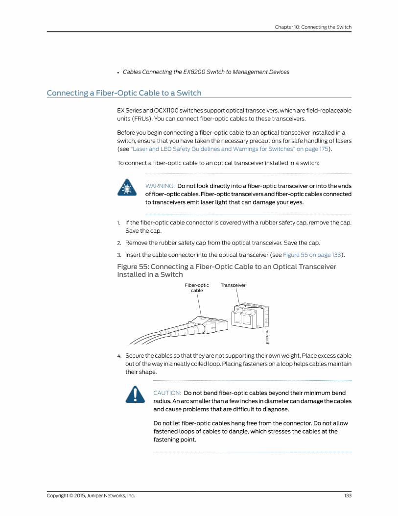
• Cables Connecting the EX8200 Switch to Management Devices
Connecting a Fiber-Optic Cable to a Switch
EXSeriesandOCX1100switches support optical transceivers,whichare field-replaceable
units (FRUs). You can connect fiber-optic cables to these transceivers.
Before you begin connecting a fiber-optic cable to an optical transceiver installed in a
switch, ensure that you have taken the necessary precautions for safe handling of lasers
(see “Laser and LED Safety Guidelines andWarnings for Switches” on page 175).
To connect a fiber-optic cable to an optical transceiver installed in a switch:
WARNING: Do not look directly into a fiber-optic transceiver or into the endsof fiber-opticcables.Fiber-optic transceiversandfiber-opticcablesconnectedto transceivers emit laser light that can damage your eyes.
1. If the fiber-optic cable connector is coveredwith a rubber safety cap, remove the cap.
Save the cap.
2. Remove the rubber safety cap from the optical transceiver. Save the cap.
3. Insert the cable connector into the optical transceiver (see Figure 55 on page 133).
Figure 55: Connecting a Fiber-Optic Cable to an Optical TransceiverInstalled in a Switch
4. Secure thecables so that theyarenot supporting their ownweight. Placeexcess cable
outof theway inaneatly coiled loop.Placing fastenersona loophelps cablesmaintain
their shape.
CAUTION: Do not bend fiber-optic cables beyond their minimum bendradius.Anarcsmaller thana few inches indiametercandamagethecablesand cause problems that are difficult to diagnose.
Do not let fiber-optic cables hang free from the connector. Do not allowfastened loops of cables to dangle, which stresses the cables at thefastening point.
133Copyright © 2015, Juniper Networks, Inc.
Chapter 10: Connecting the Switch

RelatedDocumentation
• Disconnecting a Fiber-Optic Cable from a Switch on page 152
• Installing a Transceiver in an EX Series Switch on page 113
• Maintaining Fiber-Optic Cables in Switches on page 155
• Pluggable Transceivers Supported on EX Series Switches
• Installing a Transceiver in an OCX1100 Switch
• Pluggable Transceivers Supported on OCX1100 Switches
Copyright © 2015, Juniper Networks, Inc.134
Complete Hardware Guide for EX2200 Ethernet Switches
CHAPTER 11
Performing Initial Configuration
• EX2200 Switch Default Configuration on page 135
• Connecting and Configuring an EX Series Switch (CLI Procedure) on page 139
• Connecting and Configuring an EX Series Switch (J-Web Procedure) on page 142
EX2200 Switch Default Configuration
Each EX Series switch is programmedwith a factory default configuration that contains
the values set for each configuration parameter when a switch is shipped. The default
configuration file for an EX2200 switch configures Ethernet switching and storm control
on all interfaces, configures Power over Ethernet (PoE) on all interfaces of models that
providePoE, and enables the LLDP, LLDP-MED, andRSTPprotocols and IGMPsnooping.
When you commit changes to the configuration, a new configuration file is created that
becomes the active configuration. You can always revert to the factory default
configuration—because an EX2200 switch does not have an LCD panel, use the CLI
commands to revert to the factory default configuration. See Reverting to the Default
Factory Configuration for the EX Series Switch.
The following factory default configuration file is for an EX2200 switch with 24 ports, all
of which have PoE capability:
NOTE: The factory default configuration file is different for different EX2200switchmodels.
The number of interfaces in the default configuration file depends on thenumber of ports in the EX2200 switch.
The poe stanza does not appear for models without PoE.
Uplink ports for the EX2200 switches except the EX2200-Cmodels will belisted as ge-0/1/0 to ge-0/1/3 and for the EX2200-C switches as ge-0/1/0 to
ge-0/1/1.
system {syslog {user * {any emergency;
135Copyright © 2015, Juniper Networks, Inc.
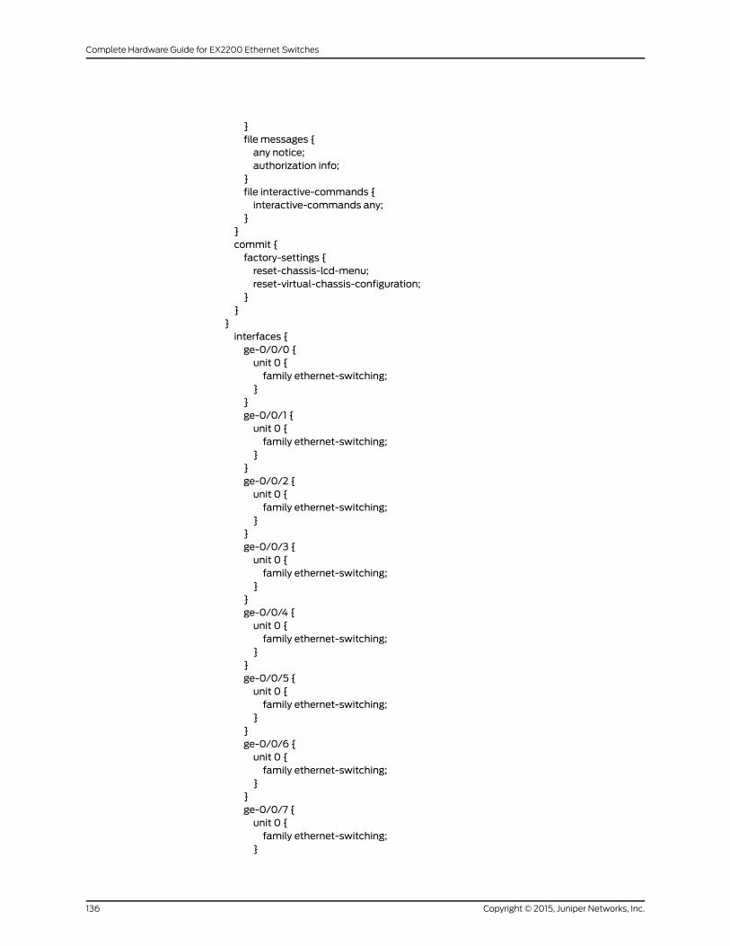
}file messages {any notice;authorization info;
}file interactive-commands {interactive-commands any;
}}commit {factory-settings {reset-chassis-lcd-menu;reset-virtual-chassis-configuration;
}}
}interfaces {ge-0/0/0 {unit 0 {family ethernet-switching;
}}ge-0/0/1 {unit 0 {family ethernet-switching;
}}ge-0/0/2 {unit 0 {family ethernet-switching;
}}ge-0/0/3 {unit 0 {family ethernet-switching;
}}ge-0/0/4 {unit 0 {family ethernet-switching;
}}ge-0/0/5 {unit 0 {family ethernet-switching;
}}ge-0/0/6 {unit 0 {family ethernet-switching;
}}ge-0/0/7 {unit 0 {family ethernet-switching;
}
Copyright © 2015, Juniper Networks, Inc.136
Complete Hardware Guide for EX2200 Ethernet Switches
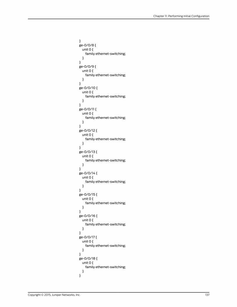
}ge-0/0/8 {unit 0 {family ethernet-switching;
}}ge-0/0/9 {unit 0 {family ethernet-switching;
}}ge-0/0/10 {unit 0 {family ethernet-switching;
}}ge-0/0/11 {unit 0 {family ethernet-switching;
}}ge-0/0/12 {unit 0 {family ethernet-switching;
}}ge-0/0/13 {unit 0 {family ethernet-switching;
}}ge-0/0/14 {unit 0 {family ethernet-switching;
}}ge-0/0/15 {unit 0 {family ethernet-switching;
}}ge-0/0/16 {unit 0 {family ethernet-switching;
}}ge-0/0/17 {unit 0 {family ethernet-switching;
}}ge-0/0/18 {unit 0 {family ethernet-switching;
}}
137Copyright © 2015, Juniper Networks, Inc.
Chapter 11: Performing Initial Configuration
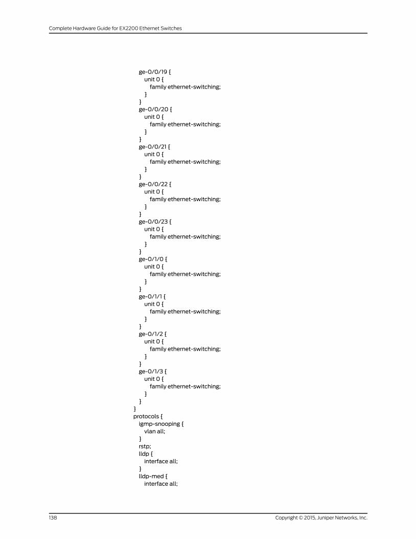
ge-0/0/19 {unit 0 {family ethernet-switching;
}}ge-0/0/20 {unit 0 {family ethernet-switching;
}}ge-0/0/21 {unit 0 {family ethernet-switching;
}}ge-0/0/22 {unit 0 {family ethernet-switching;
}}ge-0/0/23 {unit 0 {family ethernet-switching;
}}ge-0/1/0 {unit 0 {family ethernet-switching;
}}ge-0/1/1 {unit 0 {family ethernet-switching;
}}ge-0/1/2 {unit 0 {family ethernet-switching;
}}ge-0/1/3 {unit 0 {family ethernet-switching;
}}
}protocols {igmp-snooping {vlan all;
}rstp;lldp {interface all;
}lldp-med {interface all;
Copyright © 2015, Juniper Networks, Inc.138
Complete Hardware Guide for EX2200 Ethernet Switches
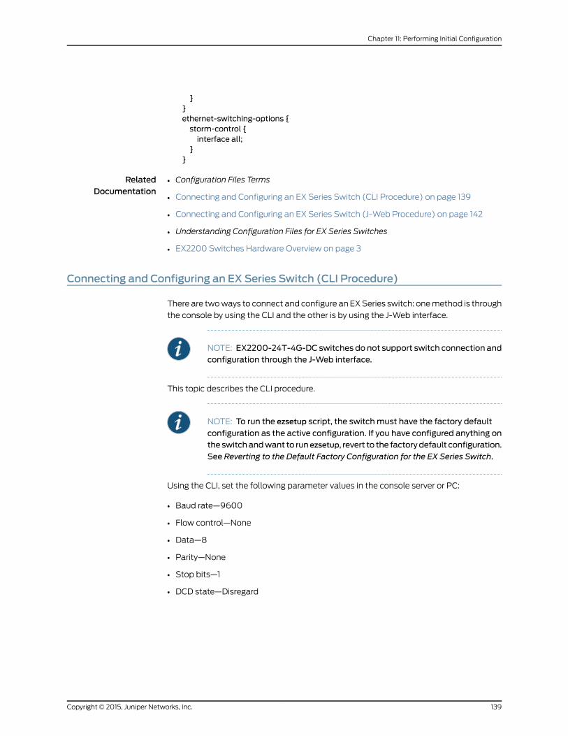
}}ethernet-switching-options {storm-control {interface all;
}}
RelatedDocumentation
Configuration Files Terms•
• Connecting and Configuring an EX Series Switch (CLI Procedure) on page 139
• Connecting and Configuring an EX Series Switch (J-Web Procedure) on page 142
• Understanding Configuration Files for EX Series Switches
• EX2200 Switches Hardware Overview on page 3
Connecting and Configuring an EX Series Switch (CLI Procedure)
There are twoways to connect and configure an EXSeries switch: onemethod is through
the console by using the CLI and the other is by using the J-Web interface.
NOTE: EX2200-24T-4G-DC switches do not support switch connection andconfiguration through the J-Web interface.
This topic describes the CLI procedure.
NOTE: To run the ezsetup script, the switchmust have the factory default
configuration as the active configuration. If you have configured anything ontheswitchandwant to runezsetup, revert to the factorydefault configuration.
See Reverting to the Default Factory Configuration for the EX Series Switch.
Using the CLI, set the following parameter values in the console server or PC:
• Baud rate—9600
• Flow control—None
• Data—8
• Parity—None
• Stop bits—1
• DCD state—Disregard
139Copyright © 2015, Juniper Networks, Inc.
Chapter 11: Performing Initial Configuration
To connect and configure the switch from the console by using the CLI:
1. Connect the console port to a laptop or PC by using the RJ-45 to DB-9 serial port
adapter. The RJ-45 cable and RJ-45 to DB-9 serial port adapter are supplied with the
switch.
For the location of the console port on different EX Series switches:
• See “EX2200 Switches Hardware Overview” on page 3.
• See Rear Panel of an EX3200 Switch.
• See Rear Panel of an EX3300 Switch.
• See Rear Panel of an EX4200 Switch.
• See EX4300 Switches Hardware Overview
• See Front Panel of an EX4500 Switch.
• See EX4550 Switches Hardware Overview
• See Switch Fabric and Routing Engine (SRE) Module in an EX6200 Switch.
• See Switch Fabric and Routing Engine (SRE) Module in an EX8208 Switch.
• See Routing Engine (RE) Module in an EX8216 Switch.
NOTE: In EX2200-C, EX4300, and EX4550 switches, you can also usethe Mini-USB Type-B console port to connect to a laptop or PC.
• For EX2200-C switches, see “Connecting an EX2200 Switch to aManagementConsoleUsingMini-USBType-BConsolePort”onpage131.
• For EX4300 switches, see Connecting an EX4300 Switch to aManagement Console Using the Mini-USB Type-B Console Port.
• For EX4550 switches, see Connecting an EX4550 Switch to aManagement Console Using the Mini-USB Type-B Console Port.
2. At the Junos OS shell prompt root%, type ezsetup.
3. Enter the hostname. This is optional.
4. Enter the root password you plan to use for this device. You are prompted to re-enter
the root password.
5. Enter yes to enable services like Telnet and SSH. By default, Telnet is not enabledand SSH is enabled.
NOTE: WhenTelnet is enabled, youwill notbeable to log in toanEXSeriesswitch through Telnet by using root credentials. Root login is supported
only for SSH access.
6. Use the Management Options page to select the management scenario:
Copyright © 2015, Juniper Networks, Inc.140
Complete Hardware Guide for EX2200 Ethernet Switches

NOTE: OnEX4500,EX6200,andEX8200switches,only theout-of-bandmanagement option is available.
• Configure in-bandmanagement. In in-bandmanagement, you configure a network
interface or an uplink module (expansion module) interface as the management
interface and connect it to the management device.
In this scenario, you have the following two options:
• Use the default VLAN.
• Create a new VLAN—If you select this option, you are prompted to specify the
VLAN name, VLAN ID, management IP address, and default gateway. Select the
ports that must be part of this VLAN.
• Configure out-of-bandmanagement. In out-of-bandmanagement, you use a
dedicatedmanagement channel (MGMT port) to connect to the management
device. Specify the IP address and gateway of the management interface. Use this
IP address to connect to the switch.
7. Specify the SNMP read community, location, and contact to configure SNMP
parameters. These parameters are optional.
8. Specify the system date and time. Select the time zone from the list. These options
are optional.
9. The configured parameters are displayed. Enter yes to commit the configuration. Theconfiguration is committed as the active configuration for the switch.
10. (For EX4500 switches only) Enter the operational mode command request chassispic-mode intraconnect to set the PICmode to intraconnect.
You can now log inwith the CLI or the J-Web interface to continue configuring the switch.
If you use the J-Web interface to continue configuring the switch, theWeb session is
redirected to the newmanagement IP address. If the connection cannot bemade, the
J-Web interface displays instructions for starting a J-Web session.
RelatedDocumentation
Connecting and Configuring an EX Series Switch (J-Web Procedure) on page 142•
• Installing and Connecting an EX2200 Switch on page 85
• Installing and Connecting an EX3200 Switch
• Installing and Connecting an EX3300 Switch
• Installing and Connecting an EX4200 Switch
• Installing and Connecting an EX4300 Switch
• Installing and Connecting an EX4550 Switch
• Installing and Connecting an EX4500 Switch
• Installing and Connecting an EX6210 Switch
• Installing and Connecting an EX8208 Switch
141Copyright © 2015, Juniper Networks, Inc.
Chapter 11: Performing Initial Configuration
• Installing and Connecting an EX8216 Switch
Connecting and Configuring an EX Series Switch (J-Web Procedure)
There are twoways to connect and configure an EXSeries switch: onemethod is through
the console by using the CLI and the other is by using the J-Web interface.
NOTE: EX2200-24T-4G-DC switches do not support switch connection andconfiguration through J-Web procedure.
This topic describes the J-Web procedure.
NOTE: Before you begin the configuration, enable a DHCP client on themanagementPCthatyouwill connect to theswitchso that thePCcanobtainan IP address dynamically.
NOTE: Read the following steps before you begin the configuration. Youmust complete the initial configuration by using EZSetup within 10minutes.The switch exits EZSetup after 10minutes and reverts to the factory defaultconfiguration, and the PC loses connectivity to the switch.
• EX2200 and EX2200-C switch—The LEDs on the network ports on thefront panel blink when the switch is in the initial setupmode.
• EX3200,EX3300,EX4200,EX4300,EX4500,EX4550,EX6200,orEX8200switch—The LCD panel displays a count-down timer when the switch is ininitial setupmode.
Copyright © 2015, Juniper Networks, Inc.142
Complete Hardware Guide for EX2200 Ethernet Switches
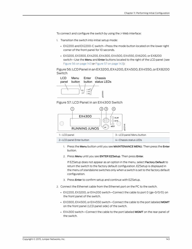
To connect and configure the switch by using the J-Web interface:
1. Transition the switch into initial setupmode:
• EX2200 and EX2200-C switch—Press the mode button located on the lower right
corner of the front panel for 10 seconds.
• EX3200, EX3300, EX4200, EX4300, EX4500, EX4550, EX6200, or EX8200
switch—Use theMenu and Enter buttons located to the right of the LCD panel (see
Figure 56 on page 143 or Figure 57 on page 143):
Figure56:LCDPanel inanEX3200,EX4200,EX4500,EX4550,orEX8200Switch
Figure 57: LCD Panel in an EX4300 Switch
3—1— LCD panel Menu buttonLCD panel
4—2— Chassis status LEDsLCD panel Enter button
1. Press theMenu button until you seeMAINTENANCEMENU. Then press the Enter
button.
2. PressMenu until you see ENTER EZSetup. Then press Enter.
If EZSetup does not appear as an option in the menu, select Factory Default to
return the switch to the factory default configuration. EZSetup is displayed in
themenu of standalone switches onlywhen a switch is set to the factory default
configuration.
3. Press Enter to confirm setup and continue with EZSetup.
2. Connect the Ethernet cable from the Ethernet port on the PC to the switch.
• EX2200, EX3200, or EX4200 switch—Connect the cable to port 0 (ge-0/0/0) on
the front panel of the switch.
• EX3300, EX4500, or EX4550 switch—Connect the cable to the port labeledMGMT
on the front panel (LCD panel side) of the switch.
• EX4300 switch—Connect the cable to the port labeledMGMT on the rear panel of
the switch.
143Copyright © 2015, Juniper Networks, Inc.
Chapter 11: Performing Initial Configuration
• EX6200switch—Connect thecable tooneof theports labeledMGMTon theSwitch
Fabric and Routing Engine (SRE) module in slot 4 or 5 in an EX6210 switch.
• EX8200 switch—Connect the cable to the port labeledMGMT on the Switch Fabric
and Routing Engine (SRE) module in slot SRE0 in an EX8208 switch or on the
Routing Engine (RE) module in slot RE0 in an EX8216 switch.
These ports are configured as the DHCP server with the default IP address, 192.168.1.1.
The switch can assign an IP address to the management PC in the IP address range
192.168.1.2 through 192.168.1.253.
3. From the PC, open aWeb browser, type http://192.168.1.1 in the address field, andpress Enter.
4. On the J-Web login page, type root as the username, leave the password field blank,and click Login.
5. On the Introduction page, click Next.
6. On the Basic Settings page, modify the hostname, the root password, and date and
time settings:
• Enter the hostname. This is optional.
• Enter a password and reenter the password.
• Specify the time zone.
• Synchronize the date and time settings of the switch with the management PC or
set themmanually by selecting the appropriate option button. This is optional.
Click Next.
7. Use the Management Options page to select the management scenario:
NOTE: OnEX4500, EX6210, and EX8200 switches, only the out-of-bandmanagement option is available.
• In-bandManagement—Use VLAN 'default' for management.
Select this option to configure all data interfaces asmembers of the default VLAN.
Click Next. Specify the management IP address and the default gateway for the
default VLAN.
• In-bandManagement—Create newVLAN formanagement.
Select this option to create amanagement VLAN. Click Next. Specify the VLAN
name, VLAN ID, member interfaces, management IP address, and default gateway
for the new VLAN.
• Out-of-bandManagement—Configuremanagement port.
Select this option to configure only the management interface. Click Next. Specify
the IP address and default gateway for the management interface.
8. Click Next.
Copyright © 2015, Juniper Networks, Inc.144
Complete Hardware Guide for EX2200 Ethernet Switches
9. On theManageAccess page, you can select options to enable Telnet, SSH, andSNMP
services. For SNMP, you can configure the read community, location, and contact.
10. Click Next. The Summary screen displays the configured settings.
11. Click Finish. The configuration is committed as the active switch configuration.
NOTE: After the configuration is committed, the connectivity betweenthePCand the switchmight be lost. To renew the connection, release andrenew the IP address by executing the appropriate commands on themanagement PC or by removing and reinserting the Ethernet cable.
12. (For EX4500 switches only) In the CLI, enter the request chassis pic-modeintraconnect operational mode command to set the PICmode to intraconnect.
You can now log in by using the CLI or the J-Web interface to continue configuring the
switch.
If you use the J-Web interface to continue configuring the switch, theWeb session is
redirected to the newmanagement IP address. If the connection cannot bemade, the
J-Web interface displays instructions for starting a J-Web session.
RelatedDocumentation
• Connecting and Configuring an EX Series Switch (CLI Procedure) on page 139
• Installing and Connecting an EX2200 Switch on page 85
• Installing and Connecting an EX3200 Switch
• Installing and Connecting an EX3300 Switch
• Installing and Connecting an EX4200 Switch
• Installing and Connecting an EX4300 Switch
• Installing and Connecting an EX4500 Switch
• Installing and Connecting an EX4550 Switch
• Installing and Connecting an EX6210 Switch
• Installing and Connecting an EX8208 Switch
• Installing and Connecting an EX8216 Switch
145Copyright © 2015, Juniper Networks, Inc.
Chapter 11: Performing Initial Configuration

Copyright © 2015, Juniper Networks, Inc.146
Complete Hardware Guide for EX2200 Ethernet Switches

PART 4
Removing Switch Components
• Removing Switch Components on page 149
147Copyright © 2015, Juniper Networks, Inc.

Copyright © 2015, Juniper Networks, Inc.148
Complete Hardware Guide for EX2200 Ethernet Switches
CHAPTER 12
Removing Switch Components
• Removing a Transceiver from a Switch on page 149
• Disconnecting a Fiber-Optic Cable from a Switch on page 152
Removing a Transceiver from a Switch
The transceivers for EX Series switches and OCX1100 switches are hot-removable and
hot-insertable field-replaceable units (FRUs): Youcan removeand replace themwithout
powering off the switch or disrupting switch functions.
NOTE: After you remove a transceiver or when you change themedia-typeconfiguration, wait for 6 seconds for the interface to display the operationalcommands.
Before you begin removing a transceiver from a switch, ensure that you have taken the
necessary precautions for safe handling of lasers (see “Laser and LED Safety Guidelines
andWarnings for Switches” on page 175).
Ensure that you have the following parts and tools available:
• An antistatic bag or an antistatic mat
• Rubber safety caps to cover the transceiver and fiber-optic cable connector
• A dust cover to cover the port
Figure 58 on page 151 shows how to remove a QSFP+ transceiver. The procedure is the
same for all types of transceivers except the CFP transceivers.
To remove a transceiver from a switch:
1. Place the antistatic bag or antistatic mat on a flat, stable surface.
2. Label the cable connected to the transceiver so that you can reconnect it correctly.
WARNING: Do not look directly into a fiber-optic transceiver or into theends of fiber-optic cables. Fiber-optic transceivers and fiber-optic cablesconnected to transceivers emit laser light that can damage your eyes.
149Copyright © 2015, Juniper Networks, Inc.

WARNING: Do not leave a fiber-optic transceiver uncovered exceptwheninserting or removing a cable. The rubber safety cap keeps the port cleanand prevents accidental exposure to laser light.
CAUTION: Do not bend fiber-optic cables beyond their minimum bendradius.Anarcsmaller thana few inches indiametercandamagethecablesand cause problems that are difficult to diagnose.
3. Remove the cable connected to the transceiver (see “Disconnecting a Fiber-Optic
Cable fromaSwitch”onpage 152).Cover the transceiverand theendofeach fiber-optic
cable connector with a rubber safety cap immediately after disconnecting the
fiber-optic cables.
Copyright © 2015, Juniper Networks, Inc.150
Complete Hardware Guide for EX2200 Ethernet Switches
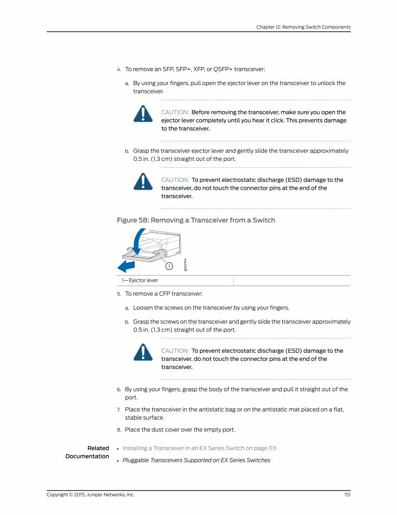
4. To remove an SFP, SFP+, XFP, or QSFP+ transceiver:
a. By using your fingers, pull open the ejector lever on the transceiver to unlock the
transceiver.
CAUTION: Before removing the transceiver, make sure you open theejector lever completely until you hear it click. This prevents damageto the transceiver.
b. Grasp the transceiver ejector lever and gently slide the transceiver approximately
0.5 in. (1.3 cm) straight out of the port.
CAUTION: To prevent electrostatic discharge (ESD) damage to thetransceiver, do not touch the connector pins at the end of thetransceiver.
Figure 58: Removing a Transceiver from a Switch
1—Ejector lever
5. To remove a CFP transceiver:
a. Loosen the screws on the transceiver by using your fingers.
b. Grasp the screws on the transceiver and gently slide the transceiver approximately
0.5 in. (1.3 cm) straight out of the port.
CAUTION: To prevent electrostatic discharge (ESD) damage to thetransceiver, do not touch the connector pins at the end of thetransceiver.
6. By using your fingers, grasp the body of the transceiver and pull it straight out of the
port.
7. Place the transceiver in the antistatic bag or on the antistatic mat placed on a flat,
stable surface.
8. Place the dust cover over the empty port.
RelatedDocumentation
Installing a Transceiver in an EX Series Switch on page 113•
• Pluggable Transceivers Supported on EX Series Switches
151Copyright © 2015, Juniper Networks, Inc.
Chapter 12: Removing Switch Components
• Installing a Transceiver in an OCX1100 Switch
• Pluggable Transceivers Supported on OCX1100 Switches
Disconnecting a Fiber-Optic Cable from a Switch
EX Series switches and OCX1100 switches have field-replaceable unit (FRU) optical
transceivers to which you can connect fiber-optic cables.
Before you begin disconnecting a fiber-optic cable from an optical transceiver installed
in a switch, ensure that you have taken the necessary precautions for safe handling of
lasers. See “Laser and LED Safety Guidelines andWarnings for Switches” on page 175.
Ensure that you have the following parts and tools available:
• A rubber safety cap to cover the transceiver
• A rubber safety cap to cover the fiber-optic cable connector
To disconnect a fiber-optic cable from an optical transceiver installed in the switch:
1. Disable theport inwhich the transceiver is installedby issuing the followingcommand:
[edit interfaces]user@switch# set interface-name disable
WARNING: Do not look directly into a fiber-optic transceiver or into theends of fiber-optic cables. Fiber-optic transceivers and fiber-optic cablesconnected to transceivers emit laser light that can damage your eyes.
2. Carefully unplug the fiber-optic cable connector from the transceiver.
3. Cover the transceiver with a rubber safety cap.
WARNING: Do not leave a fiber-optic transceiver uncovered exceptwheninserting or removing a cable. The rubber safety cap keeps the port cleanand prevents accidental exposure to laser light.
4. Cover the fiber-optic cable connector with the rubber safety cap.
RelatedDocumentation
• Connecting a Fiber-Optic Cable to a Switch on page 133
• Removing a Transceiver from a Switch on page 149
• Maintaining Fiber-Optic Cables in Switches on page 155
• Pluggable Transceivers Supported on EX Series Switches
• Pluggable Transceivers Supported on OCX1100 Switches
Copyright © 2015, Juniper Networks, Inc.152
Complete Hardware Guide for EX2200 Ethernet Switches
PART 5
Switch and Component Maintenance
• Routine Maintenance on page 155
153Copyright © 2015, Juniper Networks, Inc.

Copyright © 2015, Juniper Networks, Inc.154
Complete Hardware Guide for EX2200 Ethernet Switches
CHAPTER 13
Routine Maintenance
• Maintaining Fiber-Optic Cables in Switches on page 155
Maintaining Fiber-Optic Cables in Switches
Fiber-optic cables connect to optical transceivers that are installed in EXSeries switches
and OCX1100 switches.
Tomaintain fiber-optic cables:
• When you unplug a fiber-optic cable from a transceiver, place rubber safety caps over
the transceiver and on the end of the cable.
• Anchor fiber-optic cables to prevent stress on the connectors. When attaching a
fiber-optic cable to a transceiver, be sure to secure the fiber-optic cable so that it is
not supporting its ownweight as it hangs to the floor. Never let a fiber-optic cable hang
free from the connector.
• Avoidbending fiber-opticcablesbeyondtheirminimumbend radius.Bending fiber-optic
cables into arcs smaller than a few inches in diameter can damage the cables and
cause problems that are difficult to diagnose.
• Frequentpluggingandunpluggingof fiber-optic cables inandoutofoptical instruments
can damage the instruments, which are expensive to repair. Attach a short fiber
extension to the optical equipment. Any wear and tear due to frequent plugging and
unplugging is then absorbed by the short fiber extension, which is easier and less
expensive to replace than the instruments.
• Keep fiber-optic cable connections clean. Micro-deposits of oil and dust in the canal
of the transceiver or cable connector can cause loss of light, reduction in signal power,
and possibly intermittent problems with the optical connection.
• To clean the transceiver canal, use an appropriate fiber-cleaning device such as
RIFOCSFiberOpticAdaptorCleaningWands(partnumber946).Followthedirections
in the cleaning kit you use.
• After cleaning the transceiver, make sure that the connector tip of the fiber-optic
cable is clean. Use only an approved alcohol-free fiber-optic cable cleaning kit such
as the Opptex Cletop-S®
Fiber Cleaner. Follow the directions in the cleaning kit you
use.
155Copyright © 2015, Juniper Networks, Inc.

RelatedDocumentation
• Connecting a Fiber-Optic Cable to a Switch on page 133
• Laser and LED Safety Guidelines andWarnings for Switches on page 175
• Pluggable Transceivers Supported on EX Series Switches
• Pluggable Transceivers Supported on OCX1100 Switches
Copyright © 2015, Juniper Networks, Inc.156
Complete Hardware Guide for EX2200 Ethernet Switches

PART 6
Returning Hardware
• Returning the Switch or Switch Components on page 159
157Copyright © 2015, Juniper Networks, Inc.

Copyright © 2015, Juniper Networks, Inc.158
Complete Hardware Guide for EX2200 Ethernet Switches
CHAPTER 14
Returning the Switch or SwitchComponents
• Returning an EX2200 Switch or Component for Repair or Replacement on page 159
• Locating the Serial Number on an EX2200 Switch or Component on page 160
• Contacting Customer Support to Obtain Return Materials Authorization for
Switches on page 161
• Packing an EX2200 Switch or Component for Shipping on page 163
Returning an EX2200 Switch or Component for Repair or Replacement
If you need to return an EX2200 switch or hardware component to Juniper Networks for
repair or replacement, follow this procedure:
1. Determine the serial number of the component. For instructions, see “Locating the
Serial Number on an EX2200 Switch or Component” on page 160.
2. Obtain an RMA number from JTAC as described in “Contacting Customer Support to
Obtain Return Materials Authorization for Switches” on page 161.
NOTE: Donot return any component to JuniperNetworks unless youhavefirst obtained an RMA number. Juniper Networks reserves the right torefuse shipments that do not have an RMA. Refused shipments arereturned to the customer through collect freight.
3. Pack the switchor component for shippingasdescribed in “PackinganEX2200Switch
or Component for Shipping” on page 163.
Formore information about return and repair policies, see the customer support page at
http://www.juniper.net/support/guidelines.html .
RelatedDocumentation
EX2200 Switches Hardware Overview on page 3•
159Copyright © 2015, Juniper Networks, Inc.
Locating the Serial Number on an EX2200 Switch or Component
If you are returning an EX2200 switch or hardware component to Juniper Networks for
repair or replacement, youmust locate the serial number of the switch or component.
Youmust provide the serial number to the Juniper Networks Technical Assistance Center
(JTAC) when you contact them to obtain Return Materials Authorization (RMA).
If the switch is operational and you can access the CLI, you can list serial numbers for
the switch and for some components with a CLI command. If you do not have access to
theCLI or if the serial number for thecomponentdoesnotappear in thecommandoutput,
youcan locate theserial number ID labelon thephysical switch (seeFigure59onpage 161)
or component.
NOTE: If youwant to findtheserialnumberonthephysicalswitchcomponent,you will need to remove the component from the switch chassis, for whichyoumust have the required parts and tools available.
• Listing the Switch and Components Details with the CLI on page 160
• Locating the Chassis Serial Number ID Label on an EX2200 Switch on page 160
Listing the Switch and Components Details with the CLI
To list the switch and switch components and their serial numbers, enter the following
CLI command:
user@switch> show chassis hardwareHardware inventory:Item Version Part number Serial number DescriptionChassis CV0209096579 EX2200-24P-4GRouting Engine 0 REV 2A 750-026464 CV0209096579 EX2200-24P-4G, POEFPC 0 REV 2A 750-026464 CV0209096579 EX2200-24P-4G, POE CPU BUILTIN BUILTIN FPC CPU PIC 0 BUILTIN BUILTIN 24x 10/100/1000 Base-T PIC 1 REV 2A 750-026464 CV0209096579 4x GE SFPPower Supply 0 PS 550W ACFan Tray Fan Tray
Locating the Chassis Serial Number ID Label on an EX2200 Switch
EX2200 switches have serial number ID labels located on the rear panel of the chassis
(see Figure 59 on page 161).
Copyright © 2015, Juniper Networks, Inc.160
Complete Hardware Guide for EX2200 Ethernet Switches

Figure 59: Location of the Serial Number ID Label on EX2200 Switches
g027
011
SN: CT0209520001
Serial number ID label
EX2200-24-4G REV: X1
750-026464 REV: X3
MAC: 00:23:9C:oE:19:00
Mfg. Date20090227
MADE IN CHINA
RelatedDocumentation
Contacting Customer Support to Obtain Return Materials Authorization for Switches
on page 161
•
• Returning an EX2200 Switch or Component for Repair or Replacement on page 159
Contacting Customer Support to Obtain ReturnMaterials Authorization for Switches
If you are returning a switch or hardware component to Juniper Networks for repair or
replacement, obtain a Return Materials Authorization (RMA) from Juniper Networks
Technical Assistance Center (JTAC).
After locating the serial number of the switchor hardware component youwant to return,
open a Case with Juniper Networks Technical Assistance Center (JTAC) on theWeb or
by telephone.
For instructions on locating the serial number of the switch or hardware component you
want to return:
• See “Locating the Serial Number on an EX2200 Switch or Component” on page 160
• See Locating the Serial Number on an EX3200 Switch or Component
• See Locating the Serial Number on an EX3300 Switch or Component
• See Locating the Serial Number on an EX4200 Switch or Component
• See Locating the Serial Number on an EX4300 Switch or Component
• See Locating the Serial Number on an EX4500 Switch or Component
• See Locating the Serial Number on an EX4550 Switch or Component
• See Locating the Serial Number on an EX4600 Switch or Component
• See Locating the Serial Number on an EX6200 Switch or Component
• See Locating the Serial Number on an EX8200 Switch or Component
• See Locating the Serial Number on an EX9204 Switch or Component
• See Locating the Serial Number on an EX9208 Switch or Component
• See Locating the Serial Number on an EX9214 Switch or Component
• See Locating the Serial Number on an XRE200 External Routing Engine or Component
161Copyright © 2015, Juniper Networks, Inc.
Chapter 14: Returning the Switch or Switch Components

• See Locating the Serial Number on an EXSeries Redundant Power Systemor Redundant
Power System Components
• See Locating the Serial Number on an OCX1100 Switch or Component
Before you request an RMA from JTAC, be prepared to provide the following information:
• Your existing case number, if you have one
• Serial number of the component
• Your name, organization name, telephone number, fax number, and shipping address
• Details of the failure or problem
• Type of activity being performed on the switch when the problem occurred
• Configuration data displayed by one or more show commands
You can contact JTAC 24 hours a day, seven days a week on theWeb or by telephone:
• Case Manager at CSC: http://www.juniper.net/cm/
• Telephone: +1-888-314-JTAC1-888-314-5822, toll free in U.S., Canada, and Mexico
NOTE: For international or direct-dial options in countries without toll freenumbers, see http://www.juniper.net/support/requesting-support.html .
If you are contacting JTAC by telephone, enter your 11-digit case number followed by the
pound (#) key for an existing case, or press the star (*) key to be routed to the next
available support engineer.
The support representative validates your request and issues an RMA number for return
of the component.
RelatedDocumentation
Packing an EX2200 Switch or Component for Shipping on page 163•
• Packing an EX3200 Switch or Component for Shipping
• Packing an EX3300 Switch or Component for Shipping
• Packing an EX4200 Switch or Component for Shipping
• Packing an EX4200 Switch or Component for Shipping
• Packing an EX4300 Switch or Component for Shipping
• Packing an EX4500 Switch or Component for Shipping
• Packing an EX4550 Switch or Component for Shipping
• Packing an EX6200 Switch or Component
• Packing an EX8200 Switch or Component
• Packing an EX9200 Switch or Component
Copyright © 2015, Juniper Networks, Inc.162
Complete Hardware Guide for EX2200 Ethernet Switches

• PackinganEXSeriesRedundantPowerSystemorRedundantPowerSystemComponents
for Shipping
• Returning an EX2200 Switch or Component for Repair or Replacement on page 159
• Returning an EX3200 Switch or Component for Repair or Replacement
• Returning an EX3300 Switch or Component for Repair or Replacement
• Returning an EX4200 Switch or Component for Repair or Replacement
• Returning an EX4300 Switch or Component for Repair or Replacement
• Returning an EX4500 Switch or Component for Repair or Replacement
• Returning an EX4550 Switch or Component for Repair or Replacement
• Returning an EX6200 Switch or Component for Repair or Replacement
• Returning an EX8200 Switch or Component for Repair or Replacement
• Returning an EX9200 Switch or Component for Repair or Replacement
• Returning an EX Series RPS or RPS Component for Repair or Replacement
• Packing an OCX1100 Switch or Component for Shipping
• Returning an OCX1100 Switch or Component for Repair or Replacement
Packing an EX2200 Switch or Component for Shipping
If you are returning an EX2200 switch or component to Juniper Networks for repair or
replacement, pack the item as described in this topic.
Before you begin, ensure that you have retrieved the original shipping carton and packing
materials. Contact your JTAC representative if you do not have these materials, to learn
about approved packingmaterials. See “Contacting Customer Support to Obtain Return
Materials Authorization for Switches” on page 161.
Ensure that you have the following parts and tools available:
• Antistatic bag, one for each switch or component
• Phillips (+) screwdriver, number 2
This topic describes:
• Packing a Switch for Shipping on page 164
• Packing Switch Components for Shipping on page 164
163Copyright © 2015, Juniper Networks, Inc.
Chapter 14: Returning the Switch or Switch Components
Packing a Switch for Shipping
To pack a switch for shipping:
1. On the console or other management device connected to the switch, enter the CLI
operationalmodeand issue the followingcommandtoshutdowntheswitchsoftware:
user@switch> request system halt
Wait until a message appears on the console confirming that the operating system
has halted.
2. Disconnect power from the switch by performing one of the following:
• If the power source outlet has a power switch, set it to the OFF (0) position.
• If the power source outlet does not have a power switch, gently pull out the male
end of the power cord connected to the power source outlet.
3. Remove thecables that connect the switch toall external devices. See “Disconnecting
a Fiber-Optic Cable from a Switch” on page 152.
4. Remove all optical transceivers installed in the switch. See “Removing a Transceiver
from a Switch” on page 149.
5. If the switch is mounted on a wall or on two posts, have one person hold the switch
while another person unscrews and removes the mounting screws.
6. Use the Phillips (+) screwdriver, number 2 to remove the screws.
7. Remove the switch from the wall, rack, cabinet, or desk and place the switch in an
antistatic bag.
8. Slip on the end caps of the packaging foam on both sides of the switch.
9. Place the switch in the shipping carton.
10. Place the packing foam on top of and around the switch.
11. If you are returning accessories or FRUs with the switch, pack them as instructed in
“Packing Switch Components for Shipping” on page 164.
12. Close the top of the cardboard carton and seal it with packing tape.
13. Write the RMA number on the exterior of the carton to ensure proper tracking.
Packing Switch Components for Shipping
To pack and ship switch components:
• Place individual components in antistatic bags.
• Ensure that the components are adequately protected with packing materials and
packed so that the pieces are prevented frommoving around inside the carton.
• Close the top of the cardboard shipping carton and seal it with packing tape.
• Write the RMA number on the exterior of the carton to ensure proper tracking.
Copyright © 2015, Juniper Networks, Inc.164
Complete Hardware Guide for EX2200 Ethernet Switches

RelatedDocumentation
• Returning an EX2200 Switch or Component for Repair or Replacement on page 159
165Copyright © 2015, Juniper Networks, Inc.
Chapter 14: Returning the Switch or Switch Components

Copyright © 2015, Juniper Networks, Inc.166
Complete Hardware Guide for EX2200 Ethernet Switches

PART 7
Safety Information
• General Safety Information on page 169
• Radiation and Laser Warnings on page 175
• Installation and Maintenance Safety Information on page 181
• Power and Electrical Safety Information on page 197
167Copyright © 2015, Juniper Networks, Inc.

Copyright © 2015, Juniper Networks, Inc.168
Complete Hardware Guide for EX2200 Ethernet Switches

CHAPTER 15
General Safety Information
• General Safety Guidelines andWarnings on page 169
• Definitions of SafetyWarning Levels on page 170
• Fire Safety Requirements on page 172
• Qualified Personnel Warning on page 173
• Warning Statement for Norway and Sweden on page 174
General Safety Guidelines andWarnings
This topic applies to hardware devices in the EX Series product family, which includes
EX Series switches, the EX Series Redundant Power System (RPS), and the XRE200
External Routing Engine.
This topic also applies to hardware devices in the QFX Series and to OCX1100 switches.
The following guidelines help ensure your safety and protect the device from damage.
The list of guidelinesmightnotaddressall potentially hazardoussituations in yourworking
environment, so be alert and exercise good judgment at all times.
• Perform only the procedures explicitly described in the hardware documentation for
this device. Make sure that only authorized service personnel perform other system
services.
• Keep the area around the device clear and free from dust before, during, and after
installation.
• Keep tools away from areas where people could trip over themwhile walking.
• Do not wear loose clothing or jewelry, such as rings, bracelets, or chains, which could
become caught in the device.
• Wear safety glasses if you are working under any conditions that could be hazardous
to your eyes.
• Do not perform any actions that create a potential hazard to people or make the
equipment unsafe.
• Never attempt to lift an object that is too heavy for one person to handle.
• Never install or manipulate wiring during electrical storms.
169Copyright © 2015, Juniper Networks, Inc.
• Never install electrical jacks in wet locations unless the jacks are specifically designed
for wet environments.
• Operate the device only when it is properly grounded.
• Ensure that the separate protective earthing terminal provided on this device is
permanently connected to earth.
• Replace fuses only with fuses of the same type and rating.
• Do not open or remove chassis covers or sheet-metal parts unless instructions are
provided in the hardware documentation for this device. Such an action could cause
severe electrical shock.
• Do not push or force any objects through any opening in the chassis frame. Such an
action could result in electrical shock or fire.
• Avoid spilling liquid onto the chassis or onto any device component. Such an action
could cause electrical shock or damage the device.
• Avoid touching uninsulated electrical wires or terminals that have not been
disconnected from their power source. Such an action could cause electrical shock.
• Always ensure that all modules, power supplies, and cover panels are fully inserted
and that the installation screws are fully tightened.
RelatedDocumentation
AC Power Electrical Safety Guidelines on page 200•
• DC Power Electrical Safety Guidelines on page 203
• General Electrical Safety Guidelines andWarnings on page 197
• Maintenance and Operational Safety Guidelines andWarnings on page 190
• Installation InstructionsWarning on page 181
• Grounded EquipmentWarning on page 189
Definitions of SafetyWarning Levels
This topic applies to hardware devices in the EX Series product family, which includes
EX Series switches, the EX Series Redundant Power System (RPS), and the XRE200
External Routing Engine.
This topic also applies to hardware devices in the QFX Series and to OCX1100 switches.
Thedocumentationuses the following levels of safetywarnings (thereare two “Warning”
formats):
NOTE: Youmight find this information helpful in a particular situation, or youmight overlook this important information if it was not highlighted in a Note.
Copyright © 2015, Juniper Networks, Inc.170
Complete Hardware Guide for EX2200 Ethernet Switches
CAUTION: You need to observe the specified guidelines to prevent minorinjury or discomfort to you or severe damage to the device.
WARNING: This symbol alerts you to the risk of personal injury from a laser.
WARNING: This symbolmeansdanger.Youare inasituation thatcouldcausebodily injury. Before you work on any equipment, be aware of the hazardsinvolved with electrical circuitry and be familiar with standard practices forpreventing accidents.
Waarschuwing Dit waarschuwingssymbool betekent gevaar. U verkeert ineen situatie die lichamelijk letsel kan veroorzaken. Voordat u aan enigeapparatuur gaat werken, dient u zich bewust te zijn van de bij elektrischeschakelingen betrokken risico's en dient u opde hoogte te zijn van standaardmaatregelen om ongelukken te voorkomen.
Varoitus Tämä varoitusmerkki merkitsee vaaraa. Olet tilanteessa, joka voijohtaa ruumiinvammaan.Ennenkuin työskenteletminkään laitteistonparissa,ota selvää sähkökytkentöihin liittyvistä vaaroista ja tavanomaisistaonnettomuuksien ehkäisykeinoista.
AttentionCe symbole d'avertissement indique un danger. Vous vous trouvezdansunesituationpouvantcauserdesblessuresoudesdommagescorporels.Avant de travailler sur un équipement, soyez conscient des dangers poséspar les circuits électriques et familiarisez-vous avec les procédurescouramment utilisées pour éviter les accidents.
Warnung DiesesWarnsymbol bedeutet Gefahr. Sie befinden sich in einerSituation, die zu einer Körperverletzung führen könnte. Bevor Sie mit derArbeit an irgendeinemGerät beginnen, seien Sie sich der mit elektrischenStromkreisen verbundenen Gefahren und der Standardpraktiken zurVermeidung von Unfällen bewußt.
AvvertenzaQuesto simbolo di avvertenza indica un pericolo. La situazionepotrebbe causare infortuni alle persone. Prima di lavorare su qualsiasiapparecchiatura, occorre conoscere i pericoli relativi ai circuiti elettrici edessere al corrente delle pratiche standard per la prevenzione di incidenti.
AdvarselDette varselsymbolet betyr fare. Du befinner deg i en situasjon somkan føre til personskade. Før du utfører arbeid på utstyr, må du vareoppmerksom på de faremomentene som elektriske kretser innebærer, samtgjøre deg kjent med vanlig praksis når det gjelder å unngå ulykker.
Aviso Este símbolo de aviso indica perigo. Encontra-se numa situação quelhepoderá causar danos físicos. Antes de começar a trabalhar comqualquerequipamento, familiarize-se com os perigos relacionados com circuitos
171Copyright © 2015, Juniper Networks, Inc.
Chapter 15: General Safety Information
eléctricos, e com quaisquer práticas comuns que possam prevenir possíveisacidentes.
¡Atención! Este símbolo de aviso significa peligro. Existe riesgo para suintegridad física. Antes demanipular cualquier equipo, considerar los riesgosque entraña la corriente eléctrica y familiarizarse con los procedimientosestándar de prevención de accidentes.
Varning!Denna varningssymbol signalerar fara. Du befinner dig i en situationsom kan leda till personskada. Innan du utför arbete på någon utrustningmåste du varamedveten om farornamed elkretsar och känna till vanligtförfarande för att förebygga skador.
RelatedDocumentation
General Safety Guidelines andWarnings on page 169•
• Installation InstructionsWarning on page 181
• Maintenance and Operational Safety Guidelines andWarnings on page 190
• Grounded EquipmentWarning on page 189
• Laser and LED Safety Guidelines andWarnings for Switches on page 175
• Laser and LED Safety Guidelines andWarnings for the QFX Series
• Warning Statement for Norway and Sweden on page 174
Fire Safety Requirements
This topic applies to hardware devices in the EX Series product family, which includes
EX Series switches, the EX Series Redundant Power System (RPS), and the XRE200
External Routing Engine.
This topic also applies to hardware devices in the QFX Series and to OCX1100 switches.
In the event of a fire emergency involving switches and other network equipment, the
safety of people is the primary concern. You should establish procedures for protecting
people in the event of a fire emergency, provide safety training, and properly provision
fire-control equipment and fire extinguishers.
In addition, you should establish procedures to protect your equipment in the event of a
fire emergency. JuniperNetworksproducts shouldbe installed inanenvironment suitable
for electronic equipment. We recommend that fire suppression equipment be available
in the event of a fire in the vicinity of the equipment and that all local fire, safety, and
electrical codesandordinancesbeobservedwhenyou install andoperateyourequipment.
Fire Suppression
In the event of an electrical hazard or an electrical fire, you should first turn power off to
theequipmentat the source. ThenuseaTypeC fire extinguisher,whichusesnoncorrosive
fire retardants, to extinguish the fire.
Copyright © 2015, Juniper Networks, Inc.172
Complete Hardware Guide for EX2200 Ethernet Switches

Fire Suppression Equipment
Type C fire extinguishers, which use noncorrosive fire retardants such as carbon dioxide
andHalotron™,aremosteffective for suppressingelectrical fires. TypeC fire extinguishers
displace oxygen from the point of combustion to eliminate the fire. For extinguishing fire
on or around equipment that draws air from the environment for cooling, you should use
this type of inert oxygen displacement extinguisher instead of an extinguisher that leaves
residues on equipment.
Do not use multipurpose Type ABC chemical fire extinguishers (dry chemical fire
extinguishers). The primary ingredient in these fire extinguishers is monoammonium
phosphate,which is very sticky anddifficult to clean. In addition, in thepresenceofminute
amounts of moisture, monoammonium phosphate can become highly corrosive and
corrodes most metals.
Any equipment in a room in which a chemical fire extinguisher has been discharged is
subject to premature failure and unreliable operation. The equipment is considered to
be irreparably damaged.
NOTE: Tokeepwarrantieseffective,donotuseadrychemical fireextinguisherto control a fire at or near a Juniper Networks switch or other network deviceprovided by Juniper. If a dry chemical fire extinguisher is used, the unit is nolonger eligible for coverage under a service agreement.
We recommend that you dispose of any irreparably damaged equipment in an
environmentally responsible manner.
RelatedDocumentation
General Safety Guidelines andWarnings on page 169•
• General Electrical Safety Guidelines andWarnings on page 197
• Action to Take After an Electrical Accident on page 212
Qualified PersonnelWarning
This topic applies to hardware devices in the EX Series product family, which includes
EX Series switches, the EX Series Redundant Power System (RPS), and the XRE200
External Routing Engine.
This topic also applies to hardware devices in the QFX Series and to OCX1100 switches.
WARNING: Only trainedandqualified personnel should install or replace thedevice.
Waarschuwing Installatie en reparaties mogen uitsluitend door getraind enbevoegd personeel uitgevoerd worden.
VaroitusAinoastaankoulutettu japätevähenkilökuntasaaasentaatai vaihtaatämän laitteen.
173Copyright © 2015, Juniper Networks, Inc.
Chapter 15: General Safety Information
Attention Tout installation ou remplacement de l'appareil doit être réalisépar du personnel qualifié et compétent.
WarnungGerät nur vongeschultem, qualifiziertemPersonal installierenoderauswechseln lassen.
Avvertenza Solo personale addestrato e qualificato deve essere autorizzatoad installare o sostituire questo apparecchio.
Advarsel Kun kvalifisert personell med riktig opplæring bør montere ellerbytte ut dette utstyret.
Aviso Este equipamento deverá ser instalado ou substituído apenas porpessoal devidamente treinado e qualificado.
¡Atención! Estos equipos deben ser instalados y reemplazadosexclusivamenteporpersonal técnicoadecuadamentepreparadoycapacitado.
Varning! Denna utrustning ska endast installeras och bytas ut av utbildadoch kvalificerad personal.
RelatedDocumentation
General Safety Guidelines andWarnings on page 169•
• General Electrical Safety Guidelines andWarnings on page 197
• AC Power Electrical Safety Guidelines on page 200
• DC Power Electrical Safety Guidelines on page 203
Warning Statement for Norway and Sweden
This topic applies to hardware devices in the EX Series product family, which includes
EX Series switches, the EX Series Redundant Power System (RPS), and the XRE200
External Routing Engine.
This topic also applies to hardware devices in the QFX Series and to OCX1100 switches.
WARNING: The equipmentmust be connected to an earthedmainssocket-outlet.
Advarsel Apparatet skal kobles til en jordet stikkontakt.
Varning! Apparaten skall anslutas till jordat nätuttag.
RelatedDocumentation
• General Safety Guidelines andWarnings on page 169
Copyright © 2015, Juniper Networks, Inc.174
Complete Hardware Guide for EX2200 Ethernet Switches

CHAPTER 16
Radiation and Laser Warnings
• Laser and LED Safety Guidelines andWarnings for Switches on page 175
• Radiation fromOpen Port AperturesWarning on page 178
Laser and LED Safety Guidelines andWarnings for Switches
EX Series switches, OCX1100 switches, and the XRE200 External Routing Engine are
equipped with laser transmitters, which are considered a Class 1 Laser Product by the
U.S. Food and Drug Administration and are evaluated as a Class 1 Laser Product per EN
60825-1 requirements.
Observe the following guidelines and warnings:
• General Laser Safety Guidelines on page 175
• Class 1 Laser ProductWarning on page 176
• Class 1 LED ProductWarning on page 176
• Laser BeamWarning on page 177
General Laser Safety Guidelines
When working around ports that support optical transceivers, observe the following
safety guidelines to prevent eye injury:
• Do not look into unterminated ports or at fibers that connect to unknown sources.
• Do not examine unterminated optical ports with optical instruments.
• Avoid direct exposure to the beam.
WARNING: Unterminated optical connectors can emit invisible laserradiation. The lens in the human eye focuses all the laser power on theretina, so focusing the eye directly on a laser source—even a low-powerlaser—could permanently damage the eye.
175Copyright © 2015, Juniper Networks, Inc.
Class 1 Laser ProductWarning
WARNING: Class 1 laser product.
Waarschuwing Klasse-1 laser produkt.
Varoitus Luokan 1 lasertuote.
Attention Produit laser de classe I.
Warnung Laserprodukt der Klasse 1.
WARNING: Avvertenza Prodotto laser di Classe 1.
Advarsel Laserprodukt av klasse 1.
Aviso Produto laser de classe 1.
¡Atención! Producto láser Clase I.
Varning! Laserprodukt av klass 1.
Class 1 LED ProductWarning
WARNING: Class 1 LED product.
Waarschuwing Klasse 1 LED-product.
Varoitus Luokan 1 valodiodituote.
Attention Alarme de produit LED Class I.
Warnung Class 1 LED-Produktwarnung.
WARNING: Avvertenza Avvertenza prodotto LED di Classe 1.
Advarsel LED-produkt i klasse 1.
Aviso Produto de classe 1 com LED.
¡Atención! Aviso sobre producto LED de Clase 1.
Varning! Lysdiodprodukt av klass 1.
Copyright © 2015, Juniper Networks, Inc.176
Complete Hardware Guide for EX2200 Ethernet Switches
Laser BeamWarning
WARNING: Do not stare into the laser beam or view it directly with opticalinstruments.
WARNING: WaarschuwingNiet in de straal staren of hem rechtstreeksbekijkenmet optische instrumenten.
WARNING: VaroitusÄläkatsosäteeseenäläkätarkastelesitäsuoraanoptisenlaitteen avulla.
WARNING: AttentionNe pas fixer le faisceau des yeux, ni l'observerdirectement à l'aide d'instruments optiques.
WARNING: WarnungNicht direkt in den Strahl blicken und ihn nicht direktmit optischen Geräten prüfen.
WARNING: AvvertenzaNon fissare il raggio con gli occhi né usare strumentiottici per osservarlo direttamente.
WARNING: Advarsel Stirr eller se ikke direkte p strlenmed optiskeinstrumenter.
WARNING: AvisoNão olhe fixamente para o raio, nem olhe para eledirectamente com instrumentos ópticos.
WARNING: ¡Atención!Nomirar fijamente el haz ni observarlo directamentecon instrumentos ópticos.
WARNING: Varning! Rikta inte blicken in mot strålen och titta inte direkt påden genom optiska instrument.
177Copyright © 2015, Juniper Networks, Inc.
Chapter 16: Radiation and Laser Warnings
RelatedDocumentation
General Safety Guidelines andWarnings on page 169•
• Radiation fromOpen Port AperturesWarning on page 178
• Installation InstructionsWarning on page 181
• Grounded EquipmentWarning on page 189
• Pluggable Transceivers Supported on EX Series Switches
• Pluggable Transceivers Supported on OCX1100 Switches
Radiation fromOpen Port AperturesWarning
This topic applies to hardware devices in the EX Series product family, which includes
EX Series switches, the EX Series Redundant Power System (RPS), and the XRE200
External Routing Engine.
This topic also applies to hardware devices in the QFX Series and to OCX1100 switches.
WARNING: Because invisible radiationmight be emitted from the apertureof the portwhen no fiber cable is connected, avoid exposure to radiation anddo not stare into open apertures.
Waarschuwing Aangezien onzichtbare straling vanuit de opening van depoort kan komen als er geen fiberkabel aangesloten is, dient blootstellingaan straling en het kijken in open openingen vermeden te worden.
Varoitus Koska portin aukosta voi emittoitua näkymätöntä säteilyä, kunkuitukaapelia ei ole kytkettynä, vältä säteilylle altistumista äläkä katsoavoimiin aukkoihin.
Attention Des radiations invisibles à l'il nu pouvant traverser l'ouverture duport lorsqu'aucun câble en fibre optique n'y est connecté, il est recommandéde ne pas regarder fixement l'intérieur de ces ouvertures.
Warnung Aus der Port-Öffnung können unsichtbare Strahlen emittieren,wenn kein Glasfaserkabel angeschlossen ist. Vermeiden Sie es, sich denStrahlungen auszusetzen, und starren Sie nicht in die Öffnungen!
AvvertenzaQuando i cavi in fibranonsono inseriti, radiazioni invisibili possonoessere emesse attraverso l'apertura della porta. Evitate di esporvi alleradiazioni e non guardate direttamente nelle aperture.
AdvarselUnngåutsettelse for stråling, ogstirr ikke inn i åpninger someråpne,fordi usynlig stråling kan emiteres fra portens åpning når det ikke er tilkobleten fiberkabel.
AvisoDadaapossibilidadedeemissãode radiação invisível atravésdoorifícioda via de acesso, quando esta não tiver nenhum cabo de fibra conectado,deverá evitar a exposição à radiação e não deverá olhar fixamente paraorifícios que se encontrarem a descoberto.
Copyright © 2015, Juniper Networks, Inc.178
Complete Hardware Guide for EX2200 Ethernet Switches
¡Atención!Debidoaque laaperturadelpuertopuedeemitir radiación invisiblecuando no existe un cable de fibra conectado, evitemirar directamente a lasaperturas para no exponerse a la radiación.
Varning!Osynlig strålning kan avges från en portöppning utan anslutenfiberkabel ochdubör därför undvika att bli utsatt för strålning genomatt intestirra in i oskyddade öppningar.
RelatedDocumentation
• General Safety Guidelines andWarnings on page 169
• Laser and LED Safety Guidelines andWarnings for Switches on page 175
• Installation InstructionsWarning on page 181
• Grounded EquipmentWarning on page 189
• Laser and LED Safety Guidelines andWarnings for the QFX Series
179Copyright © 2015, Juniper Networks, Inc.
Chapter 16: Radiation and Laser Warnings

Copyright © 2015, Juniper Networks, Inc.180
Complete Hardware Guide for EX2200 Ethernet Switches

CHAPTER 17
Installation and Maintenance SafetyInformation
• Installation InstructionsWarning on page 181
• Chassis Lifting Guidelines for EX2200 Switches on page 183
• RampWarning on page 183
• Rack-Mounting and Cabinet-MountingWarnings on page 184
• Wall-MountingWarnings for EX2200 Switches on page 189
• Grounded EquipmentWarning on page 189
• Maintenance and Operational Safety Guidelines andWarnings on page 190
Installation InstructionsWarning
This topic applies to hardware devices in the EX Series product family, which includes
EX Series switches, the EX Series Redundant Power System (RPS), and the XRE200
External Routing Engine.
This topic also applies to hardware devices in the QFX Series and to OCX1100 switches.
WARNING: Read the installation instructions before you connect the deviceto a power source.
WaarschuwingRaadpleegde installatie-aanwijzingenvoordatuhetsysteemmet de voeding verbindt.
VaroitusLueasennusohjeetennen järjestelmänyhdistämistävirtalähteeseen.
AttentionAvantdebrancher lesystèmesur lasourced'alimentation,consulterles directives d'installation.
Warnung Lesen Sie die Installationsanweisungen, bevor Sie das System andie Stromquelle anschließen.
AvvertenzaConsultare le istruzionidi installazioneprimadicollegare il sistemaall'alimentatore.
Advarsel Les installasjonsinstruksjonene før systemet kobles til strømkilden.
181Copyright © 2015, Juniper Networks, Inc.

Aviso Leia as instruções de instalação antes de ligar o sistema à sua fontede energia.
¡Atención! Ver las instrucciones de instalación antes de conectar el sistemaa la red de alimentación.
Varning! Läs installationsanvisningarna innan du kopplar systemet till dessströmförsörjningsenhet.
RelatedDocumentation
General Safety Guidelines andWarnings on page 169•
• Laser and LED Safety Guidelines andWarnings for Switches on page 175
• Laser and LED Safety Guidelines andWarnings for the QFX Series
• Grounded EquipmentWarning on page 189
• Connecting AC Power to an EX2200 Switch on page 123
• Connecting AC Power to an EX3200 Switch
• Connecting AC Power to an EX3300 Switch
• Connecting AC Power to an EX4200 Switch
• Connecting AC Power to an EX4300 Switch
• Connecting AC Power to an EX4500 Switch
• Connecting AC Power to an EX4550 Switch
• Connecting AC Power to an EX4600 Switch
• Connecting AC Power to an EX6200 Switch
• Connecting AC Power to an EX8200 Switch
• Connecting AC Power to an EX9204 Switch
• Connecting AC Power to an EX9208 Switch
• Connecting AC Power to an EX9214 Switch
• Connecting DC Power to an EX2200 Switch on page 125
• Connecting DC Power to an EX3200 Switch
• Connecting DC Power to an EX4200 Switch
• Connecting DC Power to an EX4300 Switch
• Connecting DC Power to an EX4500 Switch
• Connecting DC Power to an EX4600 Switch
• Connecting DC Power to an EX4550 Switch
• Connecting DC Power to an EX6200 Switch
• Connecting DC Power to an EX8200 Switch
Copyright © 2015, Juniper Networks, Inc.182
Complete Hardware Guide for EX2200 Ethernet Switches
• Connecting DC Power to an EX9204 Switch
• Connecting DC Power to an EX9208 Switch
• Connecting DC Power to an EX9214 Switch
• Connecting AC Power to an XRE200 External Routing Engine
• Connecting DC Power to an XRE200 External Routing Engine
• Connecting AC Power to an OCX1100 Switch
• Connecting DC Power to an OCX1100 Switch
• Connecting AC Power to a QFX3100 Director Device
• Connecting AC Power to a QFX3008-I Interconnect Device with Single-PhaseWiring
Trays
• ConnectingACPower toaQFX3008-I InterconnectDevicewithThree-PhaseDeltaWiring
Trays
• Connecting ACPower to aQFX3008-I Interconnect Devicewith Three-PhaseWyeWiring
Trays
• Connecting AC Power to a QFX3500, QFX3600, or QFX3600-I Device
• Connecting DC Power to a QFX3500, QFX3600, or QFX3600-I Device
• Connecting AC Power to a QFX5100 Device
• Connecting DC Power to a QFX5100 Device
Chassis Lifting Guidelines for EX2200 Switches
Observe the following guidelines for lifting andmoving an EX2200 switch:
• Before installing theswitch, read theguidelines in “SitePreparationChecklist forEX2200
Switches” on page 61 to verify that the intended site meets the specified power,
environmental, and clearance requirements.
• Before lifting or moving the switch, disconnect all external cables.
RelatedDocumentation
General Safety Guidelines andWarnings on page 169•
• Installation InstructionsWarning on page 181
• Mounting an EX2200 Switch on page 88
RampWarning
This topic applies to hardware devices in the EX Series product family, which includes
EX Series switches, the EX Series Redundant Power System (RPS), and the XRE200
External Routing Engine.
This topic also applies to hardware devices in the QFX Series and to OCX1100 switches.
183Copyright © 2015, Juniper Networks, Inc.
Chapter 17: Installation and Maintenance Safety Information
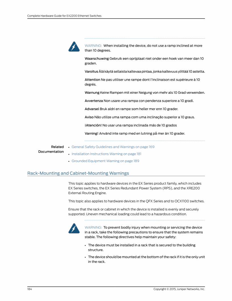
WARNING: When installing the device, do not use a ramp inclined at morethan 10 degrees.
WaarschuwingGebruik een oprijplaat niet onder een hoek vanmeer dan 10graden.
VaroitusÄläkäytäsellaistakaltevaapintaa, jonkakaltevuusylittää 10astetta.
AttentionNe pas utiliser une rampe dont l'inclinaison est supérieure à 10degrés.
WarnungKeine Rampenmit einer Neigung vonmehr als 10 Grad verwenden.
AvvertenzaNon usare una rampa con pendenza superiore a 10 gradi.
Advarsel Bruk aldri en rampe som heller mer enn 10 grader.
AvisoNão utilize uma rampa com uma inclinação superior a 10 graus.
¡Atención!No usar una rampa inclinadamás de 10 grados
Varning! Använd inte rampmed en lutning påmer än 10 grader.
RelatedDocumentation
General Safety Guidelines andWarnings on page 169•
• Installation InstructionsWarning on page 181
• Grounded EquipmentWarning on page 189
Rack-Mounting and Cabinet-MountingWarnings
This topic applies to hardware devices in the EX Series product family, which includes
EX Series switches, the EX Series Redundant Power System (RPS), and the XRE200
External Routing Engine.
This topic also applies to hardware devices in the QFX Series and to OCX1100 switches.
Ensure that the rack or cabinet in which the device is installed is evenly and securely
supported. Unevenmechanical loading could lead to a hazardous condition.
WARNING: To prevent bodily injury whenmounting or servicing the devicein a rack, take the following precautions to ensure that the system remainsstable. The following directives helpmaintain your safety:
• The devicemust be installed in a rack that is secured to the buildingstructure.
• Thedevice should bemountedat thebottomof the rack if it is the only unitin the rack.
Copyright © 2015, Juniper Networks, Inc.184
Complete Hardware Guide for EX2200 Ethernet Switches

• Whenmounting the device on a partially filled rack, load the rack from thebottom to the topwith the heaviest component at the bottom of the rack.
• If the rack is provided with stabilizing equipment, install the stabilizersbeforemounting or servicing the device in the rack.
WaarschuwingOm lichamelijk letsel te voorkomenwanneer u dit toestel ineen rekmonteert of het daar een servicebeurt geeft, moet u specialevoorzorgsmaatregelen nemen om ervoor te zorgen dat het toestel stabielblijft. De onderstaande richtlijnen worden verstrekt om uw veiligheid teverzekeren:
• De Juniper Networks switchmoet in een stellage worden geïnstalleerd dieaan een bouwsel is verankerd.
• Dit toestel dient onderaan in het rek gemonteerd teworden als het toestelhet enige in het rek is.
• Wanneer u dit toestel in een gedeeltelijk gevuld rekmonteert, dient u hetrekvanonderennaarboven te ladenmethet zwaarsteonderdeelonderaanin het rek.
• Als het rek voorzien is van stabiliseringshulpmiddelen, dient u destabilisatoren temonteren voordat u het toestel in het rekmonteert of hetdaar een servicebeurt geeft.
VaroitusKun laiteasetetaan telineeseen taihuolletaansenollessa telineessä,onnoudatettavaerityisiävarotoimia järjestelmänvakavuudensäilyttämiseksi,jotta vältytään loukkaantumiselta. Noudata seuraavia turvallisuusohjeita:
• Juniper Networks switch on asennettava telineeseen, joka on kiinnitettyrakennukseen.
• Jos telineessä ei ole muita laitteita, aseta laite telineen alaosaan.
• Jos laite asetetaan osaksi täytettyyn telineeseen, aloita kuormittaminensen alaosasta kaikkein raskaimmalla esineellä ja siirry sitten sen yläosaan.
• Jos telinettä varten on vakaimet, asenna ne ennen laitteen asettamistatelineeseen tai sen huoltamista siinä.
Attention Pour éviter toute blessure corporelle pendant les opérations demontage ou de réparation de cette unité en casier, il convient de prendre desprécautions spécialesafindemaintenir la stabilité du système. Lesdirectivesci-dessous sont destinées à assurer la protection du personnel:
• Le rack sur lequel est monté le Juniper Networks switch doit être fixé à lastructure du bâtiment.
• Si cette unité constitue la seule unitémontéeencasier, elle doit êtreplacéedans le bas.
185Copyright © 2015, Juniper Networks, Inc.
Chapter 17: Installation and Maintenance Safety Information

• Si cette unité est montée dans un casier partiellement rempli, charger lecasier de bas en haut en plaçant l'élément le plus lourd dans le bas.
• Si lecasier estéquipédedispositifs stabilisateurs, installer les stabilisateursavant demonter ou de réparer l'unité en casier.
WarnungZurVermeidungvonKörperverletzungbeimAnbringenoderWartendieser Einheit in einemGestell müssen Sie besondere Vorkehrungen treffen,um sicherzustellen, daß das System stabil bleibt. Die folgenden Richtliniensollen zur Gewährleistung Ihrer Sicherheit dienen:
• Der Juniper Networks switchmuß in einemGestell installiert werden, dasin der Gebäudestruktur verankert ist.
• Wenn diese Einheit die einzige im Gestell ist, sollte sie unten im Gestellangebracht werden.
• Bei Anbringung dieser Einheit in einem zum Teil gefüllten Gestell ist dasGestell von unten nach oben zu laden, wobei das schwerste Bauteil untenim Gestell anzubringen ist.
• Wird das Gestell mit Stabilisierungszubehör geliefert, sind zuerst dieStabilisatoren zu installieren, bevor Sie die Einheit im Gestell anbringenoder sie warten.
AvvertenzaPerevitare infortuni fisici durante ilmontaggioo lamanutenzionedi questa unità in un supporto, occorre osservare speciali precauzioni pergarantire che il sistema rimanga stabile. Le seguenti direttive vengono forniteper garantire la sicurezza personale:
• Il Juniper Networks switch deve essere installato in un telaio, il quale deveessere fissato alla struttura dell'edificio.
• Questa unità deve venire montata sul fondo del supporto, se si trattadell'unica unità damontare nel supporto.
• Quando questa unità vienemontata in un supporto parzialmente pieno,caricare il supporto dal basso all'alto, con il componente più pesantesistemato sul fondo del supporto.
• Se il supporto è dotato di dispositivi stabilizzanti, installare tali dispositiviprimadimontareodiprocedereallamanutenzionedell'unitànel supporto.
AdvarselUnngå fysiske skader under montering eller reparasjonsarbeid pådenne enheten når den befinner seg i et kabinett. Vær nøyemed at systemeter stabilt. Følgende retningslinjer er gitt for å verne om sikkerheten:
• Juniper Networks switchmå installeres i et stativ som er forankret tilbygningsstrukturen.
• Denne enheten børmonteres nederst i kabinettet hvis dette er den enesteenheten i kabinettet.
Copyright © 2015, Juniper Networks, Inc.186
Complete Hardware Guide for EX2200 Ethernet Switches
• Vedmontering av denne enheten i et kabinett som er delvis fylt, skalkabinettet lastes frabunnenogoppmeddentyngstekomponentennedersti kabinettet.
• Hvis kabinettet er utstyrt med stabiliseringsutstyr, skal stabilisatoreneinstalleres før montering eller utføring av reparasjonsarbeid på enheten ikabinettet.
Aviso Para se prevenir contra danos corporais aomontar ou reparar estaunidade numaestante, deverá tomar precauções especiais para se certificarde que o sistema possui um suporte estável. As seguintes directrizesajudá-lo-ão a efectuar o seu trabalho com segurança:
• O Juniper Networks switch deverá ser instalado numa prateleira fixa àestrutura do edificio.
• Esta unidade deverá ser montada na parte inferior da estante, caso sejaesta a única unidade a ser montada.
• Aomontar esta unidade numa estante parcialmente ocupada, coloque ositensmais pesados na parte inferior da estante, arrumando-os de baixopara cima.
• Se a estante possuir um dispositivo de estabilização, instale-o antes demontar ou reparar a unidade.
¡Atención! Para evitar lesiones durante el montaje de este equipo sobre unbastidor, o posteriormente durante sumantenimiento, se debeponermuchocuidado en que el sistema quede bien estable. Para garantizar su seguridad,proceda según las siguientes instrucciones:
• El Juniper Networks switch debe instalarse en un bastidor fijado a laestructura del edificio.
• Colocar el equipo en la parte inferior del bastidor, cuando sea la únicaunidad en el mismo.
• Cuandoesteequiposevayaa instalarenunbastidorparcialmenteocupado,comenzar la instalación desde la parte inferior hacia la superior colocandoel equipomás pesado en la parte inferior.
• Si el bastidor dispone de dispositivos estabilizadores, instalar éstos antesdemontaroprocederalmantenimientodel equipo instaladoenelbastidor.
Varning! För att undvika kroppsskada när du installerar eller utförunderhållsarbete på denna enhet på en ställningmåste du vidta särskildaförsiktighetsåtgärder föratt försäkradigomattsystemetstår stadigt. Följanderiktlinjer ges för att trygga din säkerhet:
187Copyright © 2015, Juniper Networks, Inc.
Chapter 17: Installation and Maintenance Safety Information
• Juniper Networks switchmåste installeras i en ställning som är förankradi byggnadens struktur.
• Omdenna enhet är den enda enheten på ställningen skall den installeraslängst ned på ställningen.
• Omdenna enhet installeras på en delvis fylld ställning skall ställningenfyllasnedifrånochupp,meddetyngstaenheterna längstnedpåställningen.
• Omställningenär förseddmedstabiliseringsdonskalldessamonteras fastinnan enheten installeras eller underhålls på ställningen.
RelatedDocumentation
General Safety Guidelines andWarnings on page 169•
• Installation InstructionsWarning on page 181
• Grounded EquipmentWarning on page 189
• Mounting an EX2200 Switch on page 88
• Mounting an EX3200 Switch
• Mounting an EX3300 Switch
• Mounting an EX4200 Switch
• Mounting an EX4300 Switch
• Mounting an EX4500 Switch
• Mounting an EX4550 Switch
• Mounting an EX4600 Switch in a Rack or Cabinet
• Mounting an EX6210 Switch on a Rack or Cabinet
• Mounting an EX8208 Switch on a Rack or Cabinet
• Mounting an EX8216 Switch on a Rack or Cabinet
• Mounting an EX9200 Switch on a Rack or Cabinet Using a Mechanical Lift
• Mounting an EX9204 Switch on a Rack or Cabinet Without Using a Mechanical Lift
• Mounting an EX9208 Switch on a Rack or Cabinet Without Using a Mechanical Lift
• Mounting an OCX1100 Switch
• Mounting a QFX3100 Director Device on Four Posts in a Rack or Cabinet
• Mounting a QFX3100 Director Device on Two Posts in a Rack or Cabinet
• Mounting a QFX3008-I Interconnect Device on a Rack or Cabinet Using a Mechanical
Lift
• Mounting a QFX3600 or QFX3600-I Device on Four Posts in a Rack or Cabinet
• Mounting a QFX3600 or QFX3600-I Device on Two Posts in a Rack or Cabinet
• Mounting a QFX3500 Device in a Rack or Cabinet
Copyright © 2015, Juniper Networks, Inc.188
Complete Hardware Guide for EX2200 Ethernet Switches
• Mounting a QFX5100 Device in a Rack or Cabinet
Wall-MountingWarnings for EX2200 Switches
WARNING:
Whenmounting an EX2200 switch chassis in a vertical position, orient thefront panel of the chassis downward to ensure proper airflow andmeetsafety requirements in the event of a fire.
•
• Whenwall mounting Power over Ethernet (PoE)models (EX2200-24PandEX2200-48P), install thewall-mount baffle above the units to reducethe riskofobjectsor substances falling into theair exhaustorpower supply,which could cause a fire.
RelatedDocumentation
Mounting an EX2200 Switch on aWall on page 102•
Grounded EquipmentWarning
This topic applies to hardware devices in the EX Series product family, which includes
EX Series switches, the EX Series Redundant Power System (RPS), and the XRE200
External Routing Engine.
This topic also applies to hardware devices in the QFX Series and to OCX1100 switches.
WARNING: Thedevice is intended tobegrounded.Duringnormaluse, ensurethat you have connected earth ground to the chassis.
Waarschuwing Deze apparatuur hoort geaard te worden Zorg dat dehost-computer tijdens normaal gebruik met aarde is verbonden.
Varoitus Tämä laitteisto on tarkoitettumaadoitettavaksi. Varmista, ettäisäntälaite on yhdistetty maahan normaalikäytön aikana.
Attention Cet équipement doit être relié à la terre. S'assurer que l'appareilhôte est relié à la terre lors de l'utilisation normale.
Warnung Dieses Gerät muß geerdet werden. Stellen Sie sicher, daß dasHost-Gerät während des normalen Betriebs an Erde gelegt ist.
AvvertenzaQuestaapparecchiaturadeveesserecollegataamassa.Accertarsiche il dispositivo host sia collegato alla massa di terra durante il normaleutilizzo.
AdvarselDette utstyret skal jordes. Forviss deg om vertsterminalen er jordetved normalt bruk.
189Copyright © 2015, Juniper Networks, Inc.
Chapter 17: Installation and Maintenance Safety Information
Aviso Este equipamento deverá estar ligado à terra. Certifique-se que o hostse encontra ligado à terra durante a sua utilização normal.
¡Atención!Esteequipodebeconectarsea tierra.Asegurarsedequeel equipoprincipal esté conectado a tierra durante el uso normal.
Varning! Denna utrustning är avsedd att jordas. Se till att värdenheten ärjordad vid normal användning.
RelatedDocumentation
General Safety Guidelines andWarnings on page 169•
Maintenance and Operational Safety Guidelines andWarnings
This topic applies to hardware devices in the EX Series product family, which includes
EX Series switches, the EX Series Redundant Power System (RPS), and the XRE200
External Routing Engine.
This topic also applies to hardware devices in the QFX Series and to OCX1100 switches.
Whileperforming themaintenanceactivities fordevices, observe the followingguidelines
and warnings:
• Battery HandlingWarning on page 190
• Jewelry Removal Warning on page 191
• Lightning Activity Warning on page 192
• Operating TemperatureWarning on page 193
• Product Disposal Warning on page 194
Battery HandlingWarning
WARNING: Replacing a battery incorrectly might result in an explosion.Replace a battery only with the same or equivalent type recommended bythemanufacturer. Disposeof usedbatteries according to themanufacturer'sinstructions.
Waarschuwing Er is ontploffingsgevaar als de batterij verkeerd vervangenwordt. Vervang de batterij slechts met hetzelfde of een equivalent type datdoor de fabrikant aanbevolen is. Gebruikte batterijendienenovereenkomstigfabrieksvoorschriften weggeworpen te worden.
Varoitus Räjähdyksen vaara, jos akku on vaihdettu väärään akkuun. Käytävaihtamiseen ainoastaan saman- tai vastaavantyyppistä akkua, joka onvalmistajansuosittelema.Hävitäkäytetytakutvalmistajanohjeidenmukaan.
Attention Danger d'explosion si la pile n'est pas remplacée correctement.Ne la remplacer que par une pile de type semblable ou équivalent,
Copyright © 2015, Juniper Networks, Inc.190
Complete Hardware Guide for EX2200 Ethernet Switches
recommandée par le fabricant. Jeter les piles usagées conformément auxinstructions du fabricant.
Warnung Bei Einsetzen einer falschen Batterie besteht Explosionsgefahr.Ersetzen Sie die Batterie nur durch den gleichen oder vomHerstellerempfohlenen Batterietyp. Entsorgen Sie die benutzten Batterien nach denAnweisungen des Herstellers.
Advarsel Det kan være fare for eksplosjon hvis batteriet skiftes på feil måte.Skift kunmed sammeeller tilsvarende type somer anbefalt av produsenten.Kasser brukte batterier i henhold til produsentens instruksjoner.
Avvertenza Pericolo di esplosione se la batteria non è installatacorrettamente.Sostituiresoloconunadi tipougualeoequivalente, consigliatadalproduttore. Eliminare lebatterieusatesecondo le istruzionidelproduttore.
AvisoExiste perigo de explosão se a bateria for substituída incorrectamente.Substitua a bateria por uma bateria igual ou de um tipo equivalenterecomendado pelo fabricante. Destrua as baterias usadas conforme asinstruções do fabricante.
¡Atención! Existe peligro de explosión si la batería se reemplaza demaneraincorrecta. Reemplazar la batería exclusivamente con el mismo tipo o elequivalente recomendado por el fabricante. Desechar las baterías gastadassegún las instrucciones del fabricante.
Varning!Explosionsfara vid felaktigt batteribyte. Ersätt endast batterietmedsamma batterityp som rekommenderas av tillverkaren eller motsvarande.Följ tillverkarens anvisningar vid kassering av använda batterier.
Jewelry RemovalWarning
WARNING: Before working on equipment that is connected to power lines,remove jewelry, including rings, necklaces, and watches. Metal objects heatupwhen connected to power and ground and can cause serious burns or canbe welded to the terminals.
Waarschuwing Alvorens aan apparatuur te werken die met elektrischeleidingen is verbonden, sieraden (inclusief ringen, kettingen en horloges)verwijderen. Metalen voorwerpen worden warmwanneer zemet stroom enaarde zijn verbonden, en kunnen ernstige brandwonden veroorzaken of hetmetalen voorwerp aan de aansluitklemmen lassen.
Varoitus Ennen kuin työskentelet voimavirtajohtoihin kytkettyjen laitteidenparissa, otapois kaikki korut (sormukset, kaulakorut ja kellotmukaan lukien).Metalliesineet kuumenevat, kun ne ovat yhteydessä sähkövirran ja maankanssa, janevoivataiheuttaavakaviapalovammoja tai hitsatametalliesineetkiinni liitäntänapoihin.
191Copyright © 2015, Juniper Networks, Inc.
Chapter 17: Installation and Maintenance Safety Information
AttentionAvantd'accéderàcetéquipementconnectéaux lignesélectriques,ôter toutbijou(anneaux,colliersetmontrescompris). Lorsqu'ilssontbranchésà l'alimentation et reliés à la terre, les objets métalliques chauffent, ce quipeutprovoquerdesblessuresgravesousouder l'objetmétalliqueauxbornes.
Warnung Vor der Arbeit an Geräten, die an das Netz angeschlossen sind,jeglichen Schmuck (einschließlich Ringe, Ketten und Uhren) abnehmen.Metallgegenstände erhitzen sich, wenn sie an das Netz und die Erdeangeschlossen werden, und können schwere Verbrennungen verursachenoder an die Anschlußklemmen angeschweißt werden.
Avvertenza Prima di intervenire su apparecchiature collegate alle linee dialimentazione, togliersi qualsiasi monile (inclusi anelli, collane, braccialettied orologi). Gli oggetti metallici si riscaldano quando sono collegati tra puntidi alimentazione emassa: possono causare ustioni gravi oppure il metallopuò saldarsi ai terminali.
Advarsel Fjern alle smykker (inkludert ringer, halskjeder og klokker) før duskal arbeidepåutstyr somer koblet til kraftledninger.Metallgjenstander somer koblet til kraftledninger og jord blir svært varme og kan forårsake alvorligebrannskader eller smelte fast til polene.
Aviso Antes de trabalhar em equipamento que esteja ligado a linhas decorrente, retire todas as jóias que estiver a usar (incluindo anéis, fios erelógios). Os objectosmetálicos aquecerão em contacto com a corrente eem contacto com a ligação à terra, podendo causar queimaduras graves ouficarem soldados aos terminais.
¡Atención! Antes de operar sobre equipos conectados a líneas dealimentación, quitarse las joyas (incluidos anillos, collares y relojes). Losobjetosdemetal secalientancuandoseconectana laalimentaciónyatierra,lo que puede ocasionar quemaduras graves o que los objetosmetálicosqueden soldados a los bornes.
Varning! Tag av alla smycken (inklusive ringar, halsband och armbandsur)innanduarbetarpåutrustningsomärkopplad till kraftledningar.Metallobjekthettas upp när de kopplas ihopmed ström och jord och kan förorsakaallvarliga brännskador; metallobjekt kan också sammansvetsasmedkontakterna.
Lightning ActivityWarning
WARNING: Donotworkon thesystemorconnectordisconnectcablesduringperiods of lightning activity.
Waarschuwing Tijdens onweer dat gepaard gaat met bliksem, dient u nietaan het systeem te werken of kabels aan te sluiten of te ontkoppelen.
Copyright © 2015, Juniper Networks, Inc.192
Complete Hardware Guide for EX2200 Ethernet Switches
Varoitus Älä työskentele järjestelmän parissa äläkä yhdistä tai irrotakaapeleita ukkosilmalla.
AttentionNe pas travailler sur le système ni brancher ou débrancher lescâbles pendant un orage.
Warnung Arbeiten Sie nicht am System und schließen Sie keine Kabel anbzw. trennen Sie keine ab, wenn es gewittert.
AvvertenzaNon lavorare sul sistema o collegare oppure scollegare i cavidurante un temporale con fulmini.
AdvarselUtfør aldri arbeidpåsystemet, eller koble kabler til eller fra systemetnår det tordner eller lyner.
AvisoNão trabalhe no sistema ou ligue e desligue cabos durante períodosdemau tempo (trovoada).
¡Atención!No operar el sistema ni conectar o desconectar cables durante eltranscurso de descargas eléctricas en la atmósfera.
Varning!Vid åska skall du aldrig utföra arbete på systemet eller ansluta ellerkoppla loss kablar.
Operating TemperatureWarning
WARNING: To prevent the device from overheating, do not operate it in anarea that exceeds themaximum recommended ambient temperature of104° F (40° C) for EX6200 switches, EX8208 switches, EX8216 switches,QFXSeriesdevices,OCX1100switches,andXRE200ExternalRoutingEnginesand 113°F(45°C) forEX2200,EX3300,EX3200,EX4200,EX4300,EX4500,and EX4550 switches. To prevent airflow restriction, allow at least 6 in.(15.2 cm) of clearance around the ventilation openings.
WaarschuwingOm te voorkomen dat welke switch van de Juniper Networksrouter dan ook oververhit raakt, dient u deze niet te bedienen op een plaatswaar demaximale aanbevolen omgevingstemperatuur van 40° Cwordtoverschreden. Om te voorkomen dat de luchtstroomwordt beperkt, dient erminstens 15,2 cm speling rond de ventilatie-openingen te zijn.
Varoitus Ettei Juniper Networks switch-sarjan reititin ylikuumentuisi, sitä eisaa käyttää tilassa, jonka lämpötila ylittää korkeimman suositellunympäristölämpötilan 40° C. Ettei ilmanvaihto estyisi, tuuletusaukkojenympärille on jätettävä ainakin 15,2 cm tilaa.
Attention Pour éviter toute surchauffe des routeurs de la gamme JuniperNetworks switch, ne l'utilisez pas dans une zoneoù la température ambianteest supérieure à 40° C. Pour permettre un flot d'air constant, dégagez unespace d'aumoins 15,2 cm autour des ouvertures de ventilations.
193Copyright © 2015, Juniper Networks, Inc.
Chapter 17: Installation and Maintenance Safety Information
WarnungUmeinenRouterder switchvorÜberhitzungzuschützen,darfdiesernicht in einer Gegend betrieben werden, in der die Umgebungstemperaturdas empfohlene Maximum von 40° C überschreitet. Um Lüftungsverschlußzu verhindern, achten Sie darauf, daßmindestens 15,2 cm lichter Raum umdie Lüftungsöffnungen herum frei bleibt.
Avvertenza Per evitare il surriscaldamento dei switch, non adoperateli in unlocale che ecceda la temperatura ambientale massima di 40° C. Per evitareche lacircolazionedell'aria sia impedita, lasciateunospaziodialmeno 15.2cmdi fronte alle aperture delle ventole.
AdvarselUnngåoveropphetingaveventuelle rutere i JuniperNetworksswitchDisse skal ikke brukes på steder der den anbefalte maksimaleomgivelsestemperaturen overstiger 40° C (104° F). Sørg for at klaringenrundt lufteåpningene er minst 15,2 cm (6 tommer) for å forhindre nedsattluftsirkulasjon.
Aviso Para evitar o sobreaquecimento do encaminhador Juniper Networksswitch, não utilize este equipamento numa área que exceda a temperaturamáxima recomendada de 40° C. Para evitar a restrição à circulação de ar,deixe pelomenos um espaço de 15,2 cm à volta das aberturas de ventilação.
¡Atención! Para impedir que un encaminador de la serie Juniper Networksswitch se recaliente, no lo haga funcionar en un área en la que se supere latemperatura ambientemáxima recomendada de 40° C. Para impedir larestricciónde laentradadeaire, dejeunespaciomínimode 15,2 cmalrededorde las aperturas para ventilación.
Varning! Förhindra att en Juniper Networks switch överhettas genomatt inteanvända den i ett område där denmaximalt rekommenderadeomgivningstemperaturenpå40°Cöverskrids. Förhindraatt luftcirkulationeninskränksgenomattse till attdet finns fritt utrymmepåminst 15,2cmomkringventilationsöppningarna.
Product DisposalWarning
WARNING: Disposal of this devicemust be handled according to all nationallaws and regulations.
Waarschuwing Dit produkt dient volgens alle landelijke wetten envoorschriften te worden afgedankt.
VaroitusTämän tuotteen lopullisesta hävittämisestä tulee huolehtia kaikkiavaltakunnallisia lakeja ja säännöksiä noudattaen.
Attention Lamise au rebut définitive de ce produit doit être effectuéeconformément à toutes les lois et réglementations en vigueur.
Copyright © 2015, Juniper Networks, Inc.194
Complete Hardware Guide for EX2200 Ethernet Switches
Warnung Dieses Produkt muß den geltenden Gesetzen und Vorschriftenentsprechend entsorgt werden.
Avvertenza L'eliminazione finale di questo prodotto deve essere eseguitaosservando le normative italiane vigenti in materia
AdvarselEndeligdisponeringavdetteproduktetmåskje ihenholdtil nasjonalelover og forskrifter.
Aviso A descartagem final deste produto deverá ser efectuada de acordocom os regulamentos e a legislação nacional.
¡Atención! El desecho final de este producto debe realizarse según todas lasleyes y regulaciones nacionales
Varning!Slutlig kasseringavdennaproduktbör skötas i enlighetmed landetsalla lagar och föreskrifter.
RelatedDocumentation
• General Safety Guidelines andWarnings on page 169
• General Electrical Safety Guidelines andWarnings on page 197
• AC Power Electrical Safety Guidelines on page 200
• DC Power Electrical Safety Guidelines on page 203
• Laser and LED Safety Guidelines andWarnings for Switches on page 175
• Laser and LED Safety Guidelines andWarnings for the QFX Series
• Installation InstructionsWarning on page 181
• Grounded EquipmentWarning on page 189
195Copyright © 2015, Juniper Networks, Inc.
Chapter 17: Installation and Maintenance Safety Information

Copyright © 2015, Juniper Networks, Inc.196
Complete Hardware Guide for EX2200 Ethernet Switches

CHAPTER 18
Power and Electrical Safety Information
• General Electrical Safety Guidelines andWarnings on page 197
• Prevention of Electrostatic Discharge Damage on page 198
• AC Power Electrical Safety Guidelines on page 200
• AC Power DisconnectionWarning on page 202
• DC Power Electrical Safety Guidelines on page 203
• DC Power DisconnectionWarning on page 205
• DC Power Grounding Requirements andWarning on page 207
• DC PowerWiring SequenceWarning on page 208
• DC PowerWiring TerminationsWarning on page 210
• TN PowerWarning on page 211
• Action to Take After an Electrical Accident on page 212
General Electrical Safety Guidelines andWarnings
This topic applies to hardware devices in the EX Series product family, which includes
EX Series switches, the EX Series Redundant Power System (RPS), and the XRE200
External Routing Engine.
This topic also applies to hardware devices in the QFX Series and to OCX1100 switches.
WARNING: Certain ports on the device are designed for use as intrabuilding(within-the-building) interfaces only (Type 2 or Type 4 ports as described inGR-1089-CORE) and require isolation from the exposedoutside plant (OSP)cabling. To comply with NEBS requirements and protect against lightningsurges and commercial power disturbances, the intrabuilding portsmust notbemetallically connected to interfaces that connect to theOSP or its wiring.The intrabuilding ports on the device are suitable for connection tointrabuilding or unexposed wiring or cabling only. The addition of primaryprotectors is not sufficient protection for connecting these interfacesmetallically to OSPwiring.
197Copyright © 2015, Juniper Networks, Inc.
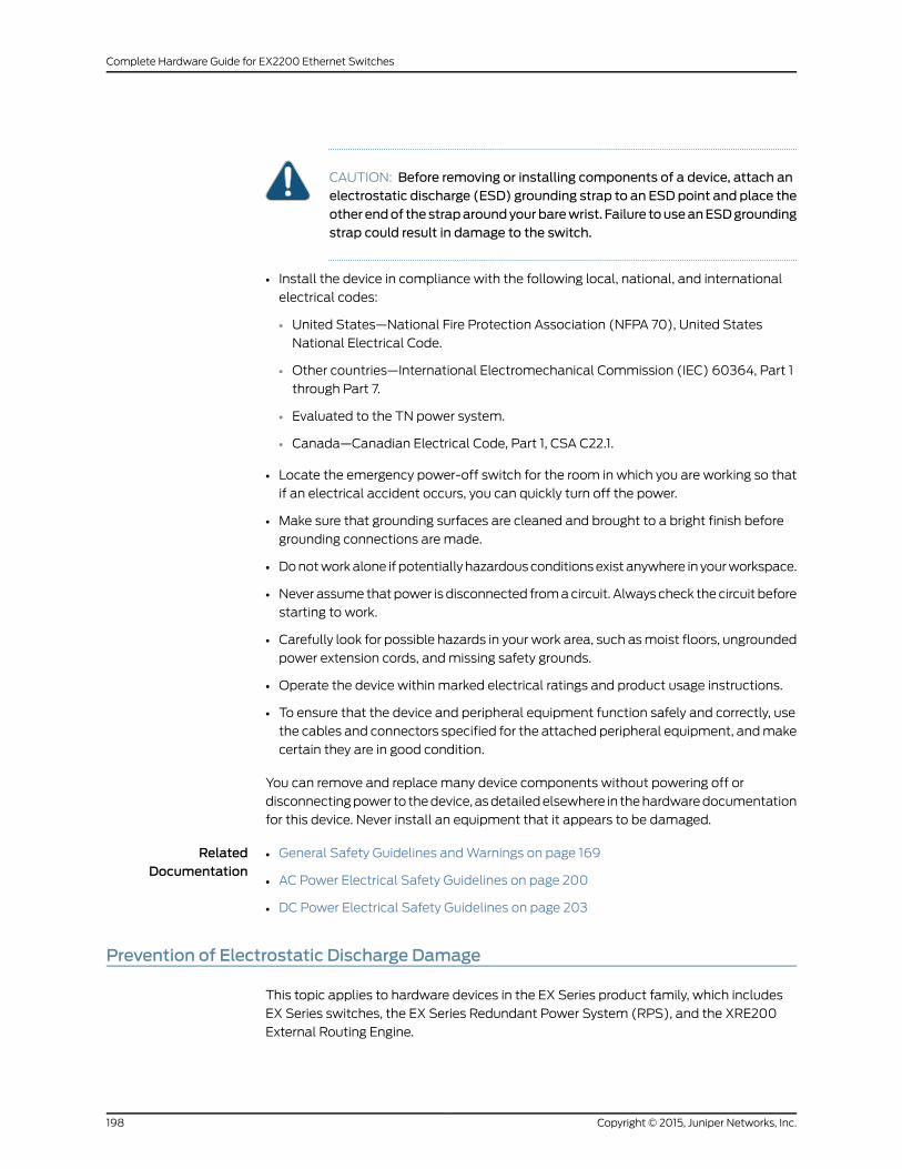
CAUTION: Before removing or installing components of a device, attach anelectrostatic discharge (ESD) grounding strap to an ESD point and place theother endof thestraparoundyourbarewrist. Failure touseanESDgroundingstrap could result in damage to the switch.
• Install the device in compliance with the following local, national, and international
electrical codes:
• United States—National Fire Protection Association (NFPA 70), United States
National Electrical Code.
• Other countries—International Electromechanical Commission (IEC) 60364, Part 1
through Part 7.
• Evaluated to the TN power system.
• Canada—Canadian Electrical Code, Part 1, CSA C22.1.
• Locate the emergency power-off switch for the room in which you are working so that
if an electrical accident occurs, you can quickly turn off the power.
• Make sure that grounding surfaces are cleaned and brought to a bright finish before
grounding connections are made.
• Donotworkalone if potentially hazardousconditionsexist anywhere in yourworkspace.
• Never assume thatpower is disconnected fromacircuit. Always check thecircuit before
starting to work.
• Carefully look for possible hazards in your work area, such asmoist floors, ungrounded
power extension cords, andmissing safety grounds.
• Operate the device within marked electrical ratings and product usage instructions.
• To ensure that the device and peripheral equipment function safely and correctly, use
the cables and connectors specified for the attached peripheral equipment, andmake
certain they are in good condition.
You can remove and replace many device components without powering off or
disconnectingpower to thedevice, asdetailedelsewhere in thehardwaredocumentation
for this device. Never install an equipment that it appears to be damaged.
RelatedDocumentation
General Safety Guidelines andWarnings on page 169•
• AC Power Electrical Safety Guidelines on page 200
• DC Power Electrical Safety Guidelines on page 203
Prevention of Electrostatic Discharge Damage
This topic applies to hardware devices in the EX Series product family, which includes
EX Series switches, the EX Series Redundant Power System (RPS), and the XRE200
External Routing Engine.
Copyright © 2015, Juniper Networks, Inc.198
Complete Hardware Guide for EX2200 Ethernet Switches
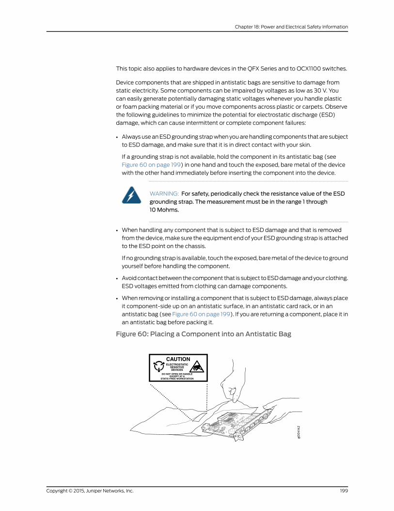
This topic also applies to hardware devices in the QFX Series and to OCX1100 switches.
Device components that are shipped in antistatic bags are sensitive to damage from
static electricity. Some components can be impaired by voltages as low as 30 V. You
can easily generate potentially damaging static voltages whenever you handle plastic
or foam packing material or if youmove components across plastic or carpets. Observe
the following guidelines to minimize the potential for electrostatic discharge (ESD)
damage, which can cause intermittent or complete component failures:
• AlwaysuseanESDgroundingstrapwhenyouarehandlingcomponents thatare subject
to ESD damage, andmake sure that it is in direct contact with your skin.
If a grounding strap is not available, hold the component in its antistatic bag (see
Figure 60 on page 199) in one hand and touch the exposed, bare metal of the device
with the other hand immediately before inserting the component into the device.
WARNING: For safety, periodically check the resistance value of the ESDgrounding strap. Themeasurementmust be in the range 1 through10Mohms.
• When handling any component that is subject to ESD damage and that is removed
from thedevice,make sure the equipment endof your ESDgrounding strap is attached
to the ESD point on the chassis.
If nogrounding strap is available, touch theexposed, baremetal of thedevice toground
yourself before handling the component.
• Avoidcontactbetween thecomponent that is subject toESDdamageandyourclothing.
ESD voltages emitted from clothing can damage components.
• When removing or installing a component that is subject to ESDdamage, always place
it component-side up on an antistatic surface, in an antistatic card rack, or in an
antistatic bag (see Figure 60on page 199). If you are returning a component, place it in
an antistatic bag before packing it.
Figure 60: Placing a Component into an Antistatic Bag
6xGE
SFP
0
1
2
3
4
5
CAUTIONELECTROSTATIC
SENSITIVEDEVICES
DO NOT OPEN OR HANDLEEXCEPT AT A
STATIC-FREE WORKSTATION
199Copyright © 2015, Juniper Networks, Inc.
Chapter 18: Power and Electrical Safety Information
CAUTION: ANSI/TIA/EIA-568 cables such as Category 5e and Category 6can get electrostatically charged. To dissipate this charge, always groundthe cables to a suitable and safe earth groundbefore connecting them to thesystem.
RelatedDocumentation
General Safety Guidelines andWarnings on page 169•
• See EX2200 Switches Hardware Overview on page 3 for the ESD point location.
• See Rear Panel of an EX3200 Switch for the ESD point location.
• See Rear Panel of an EX3300 Switch for the ESD point location.
• See Rear Panel of an EX4200 Switch for the ESD point location.
• See EX4300 Switches Hardware Overview for the ESD point location.
• See Front Panel of an EX4500 Switch for the ESD point location.
• See EX4550 Switches Hardware Overview for the ESD point location.
• See Chassis Physical Specifications of an EX6210 Switch for the ESD point location.
• See Chassis Physical Specifications of an EX8208 Switch for the ESD point location.
• See Chassis Physical Specifications of an EX8216 Switch for the ESD point location.
• See EX9204 Switch Hardware Overview for the ESD point location.
• See EX9208 Switch Hardware Overview for the ESD point location.
• See EX9214 Switch Hardware Overview for the ESD point location.
• SeeOCX1100 Switches Hardware Overview for the ESD point location.
• SeeQFX3008-I Interconnect Device Overview for the ESD point location.
• See Front Panel of a QFX3500 Device for the ESD point location.
• See Front Panel of a QFX3600 Device for the ESD point location.
• See Physical Description of a Redundant Power System
• See Port Panel of an EX4600 Switch for the ESD point location.
• See Port Panel of a QFX5100-48S Device for the ESD point location.
• See Port Panel of a QFX5100-24Q Device for the ESD point location.
• See Port Panel of a QFX5100-96S Device for the ESD point location.
AC Power Electrical Safety Guidelines
This topic applies to hardware devices in the EX Series product family, which includes
EX Series switches, the EX Series Redundant Power System (RPS), and the XRE200
External Routing Engine.
This topic also applies to hardware devices in the QFX Series and to OCX1100 switches.
Copyright © 2015, Juniper Networks, Inc.200
Complete Hardware Guide for EX2200 Ethernet Switches

CAUTION: For devices with AC power supplies, an external surge protectivedevice (SPD)must be used at the AC power source.
The following electrical safety guidelines apply to AC-powered devices:
• Note the following warnings printed on the device:
“CAUTION: THIS UNIT HASMORE THANONE POWER SUPPLY CORD. DISCONNECT
ALL POWER SUPPLY CORDS BEFORE SERVICING TO AVOID ELECTRIC SHOCK.”
“ATTENTION: CET APPAREIL COMPORTE PLUS D'UN CORDON D'ALIMENTATION.AFIN DE PRÉVENIR LES CHOCS ÉLECTRIQUES, DÉBRANCHER TOUT CORDON
D'ALIMENTATION AVANT DE FAIRE LE DÉPANNAGE.”
• AC-powereddevicesare shippedwitha three-wireelectrical cordwithagrounding-type
plug that fits only a grounding-typepower outlet. Donot circumvent this safety feature.
Equipment grounding must comply with local and national electrical codes.
• Youmustprovideanexternal certifiedcircuit breaker ratedminimum20A in thebuilding
installation.
• The power cord serves as the main disconnecting device for the AC-powered device.
The socket outlet must be near the AC-powered device and be easily accessible.
• For devices that havemore than one power supply connection, youmust ensure that
all power connections are fully disconnected so that power to the device is completely
removed to prevent electric shock. To disconnect power, unplug all power cords (one
for each power supply).
Power CableWarning (Japanese)
WARNING: The attached power cable is only for this product. Do not use the cable for another product.
RelatedDocumentation
General Safety Guidelines andWarnings on page 169•
• General Electrical Safety Guidelines andWarnings on page 197
• Multiple Power Supplies DisconnectionWarning
• Connecting AC Power to an EX2200 Switch on page 123
• Connecting AC Power to an EX3200 Switch
• Connecting AC Power to an EX3300 Switch
• Connecting AC Power to an EX4200 Switch
201Copyright © 2015, Juniper Networks, Inc.
Chapter 18: Power and Electrical Safety Information
• Connecting AC Power to an EX4300 Switch
• Connecting AC Power to an EX4500 Switch
• Connecting AC Power to an EX4550 Switch
• Connecting AC Power to an EX4600 Switch
• Connecting AC Power to an EX6200 Switch
• Connecting AC Power to an EX8200 Switch
• Connecting AC Power to an EX9204 Switch
• Connecting AC Power to an EX9208 Switch
• Connecting AC Power to an EX9214 Switch
• Connecting AC Power to an XRE200 External Routing Engine
• Connecting AC Power to an OCX1100 Switch
• Connecting AC Power to a QFX3100 Director Device
• Connecting AC Power to a QFX3008-I Interconnect Device with Single-PhaseWiring
Trays
• ConnectingACPower toaQFX3008-I InterconnectDevicewithThree-PhaseDeltaWiring
Trays
• Connecting ACPower to aQFX3008-I Interconnect Devicewith Three-PhaseWyeWiring
Trays
• Connecting AC Power to a QFX3500, QFX3600, or QFX3600-I Device
• Connecting AC Power to a QFX5100 Device
AC Power DisconnectionWarning
This topic applies to hardware devices in the EX Series product family, which includes
EX Series switches, the EX Series Redundant Power System (RPS), and the XRE200
External Routing Engine.
This topic also applies to hardware devices in the QFX Series and to OCX1100 switches.
WARNING: Before working on the switch or near power supplies, unplug allthe power cords from an AC switch.
Waarschuwing Voordat u aan een frame of in de nabijheid van voedingenwerkt, dient u bij wisselstroom toestellen de stekker van het netsnoer uit hetstopcontact te halen.
Varoitus Kytke irti vaihtovirtalaitteiden virtajohto, ennen kuin teet mitäänasennuspohjalle tai työskentelet virtalähteiden läheisyydessä.
Copyright © 2015, Juniper Networks, Inc.202
Complete Hardware Guide for EX2200 Ethernet Switches
AttentionAvantde travailler surunchâssisouàproximitéd'unealimentationélectrique, débrancher le cordon d'alimentation des unités en courantalternatif.
Warnung Bevor Sie an einem Chassis oder in der Nähe von Netzgerätenarbeiten, ziehen Sie bei Wechselstromeinheiten das Netzkabel ab bzw.
AvvertenzaPrimadi lavorare suun telaioo intornoadalimentatori, scollegareil cavo di alimentazione sulle unità CA.
Advarsel Før det utføres arbeid på kabinettet eller det arbeides i nærhetenav strømforsyningsenheter, skal strømledningen trekkes ut påvekselstrømsenheter.
AvisoAntesdetrabalharnumchassis,ouantesdetrabalharpertodeunidadesde fornecimento de energia, desligue o cabo de alimentação nas unidadesde corrente alternada.
¡Atención!Antes demanipular el chasis de un equipoo trabajar cerca deunafuentedealimentación, desenchufar el cabledealimentaciónen losequiposde corriente alterna (CA).
Varning! Innanduarbetarmedett chassi eller nära strömförsörjningsenheterskall du för växelströmsenheter dra ur nätsladden.
RelatedDocumentation
General Safety Guidelines andWarnings on page 169•
• General Electrical Safety Guidelines andWarnings on page 197
• AC Power Electrical Safety Guidelines on page 200
DC Power Electrical Safety Guidelines
This topic applies to hardware devices in the EX Series product family, which includes
EX Series switches and the XRE200 External Routing Engine.
This topic also applies to hardware devices in the QFX Series and to OCX1100 switches.
203Copyright © 2015, Juniper Networks, Inc.
Chapter 18: Power and Electrical Safety Information

• A DC-powered device is equipped with a DC terminal block that is rated for the power
requirements of a maximally configured device.
NOTE: Tosupplysufficientpower, terminate theDC inputwiringona facilityDC source that is capable of supplying:
• Minimum of 7.5 A at –48 VDC for EX2200 and EX3300 switches
• Minimum of 8 A at –48 VDC for EX3200 and EX4200 switches
• Minimumof20Aat–48VDCforEX4300,EX4500,andEX4550switches
• Minimum of 50 A at –48 VDC for EX6210 switches
• Minimum of 60 A at –48 VDC for EX8208 switches
• Minimum of 100 A at –48 VDC for EX8216 switches
• Minimumof7Aat–48VDCforQFX3500,EX4600,andQFX5100devices
• Minimum of 8 A at –48 VDC for QFX3600 devices
• Minimum of 7 A at –48 VDC for OCX1100 switches
Incorporate an easily accessible disconnect device into the facility wiring. Be sure to
connect the ground wire or conduit to a solid office earth ground. A closed loop ring is
recommended for terminating the ground conductor at the ground stud.
• Run two wires from the circuit breaker box to a source of 48 VDC.
• A DC-powered device that is equipped with a DC terminal block is intended only for
installation in a restricted access location. In the United States, a restricted access
area isone inaccordancewithArticles 110-16, 110-17, and 110-18of theNational Electrical
Code ANSI/NFPA 70.
NOTE: Primary overcurrent protection is provided by the building circuitbreaker. This breaker must protect against excess currents, short circuits,and earth grounding faults in accordance with NEC ANSI/NFPA 70.
• Ensure that the polarity of the DC input wiring is correct. Under certain conditions,
connections with reversed polarity might trip the primary circuit breaker or damage
the equipment.
• For personal safety, connect the green and yellowwire to safety (earth) ground at both
the device and the supply side of the DC wiring.
• Themarked input voltage of –48 VDC for a DC-powered device is the nominal voltage
associated with the battery circuit, and any higher voltages are only to be associated
with float voltages for the charging function.
• Because the device is a positive ground system, youmust connect the positive lead to
the terminal labeled RTN, the negative lead to the terminal labeled –48 VDC, and the
earth ground to the device grounding points.
Copyright © 2015, Juniper Networks, Inc.204
Complete Hardware Guide for EX2200 Ethernet Switches
RelatedDocumentation
General Safety Guidelines andWarnings on page 169•
• General Electrical Safety Guidelines andWarnings on page 197
• DC Power DisconnectionWarning on page 205
• DC Power Grounding Requirements andWarning on page 207
• DC PowerWiring SequenceWarning on page 208
• DC PowerWiring TerminationsWarning on page 210
• Connecting DC Power to an EX2200 Switch on page 125
• Connecting DC Power to an EX3200 Switch
• Connecting DC Power to an EX4200 Switch
• Connecting DC Power to an EX4300 Switch
• Connecting DC Power to an EX4500 Switch
• Connecting DC Power to an EX4550 Switch
• Connecting DC Power to an EX4600 Switch
• Connecting DC Power to an EX6200 Switch
• Connecting DC Power to an EX8200 Switch
• Connecting DC Power to an EX9204 Switch
• Connecting DC Power to an EX9208 Switch
• Connecting DC Power to an EX9214 Switch
• Connecting DC Power to an OCX1100 Switch
• Connecting DC Power to an XRE200 External Routing Engine
• Connecting DC Power to a QFX3500, QFX3600, or QFX3600-I Device
• Connecting DC Power to a QFX5100 Device
DC Power DisconnectionWarning
This topic applies to hardware devices in the EX Series product family, which includes
EX Series switches and the XRE200 External Routing Engine.
This topic also applies to hardware devices in the QFX Series and to OCX1100 switches.
WARNING: Before performing any of the DC power procedures, ensure thatpower is removed from the DC circuit. To ensure that all power is off, locatethe circuit breaker on the panel board that services the DC circuit, switch thecircuit breaker to the OFF position, and tape the device handle of the circuitbreaker in the OFF position.
205Copyright © 2015, Juniper Networks, Inc.
Chapter 18: Power and Electrical Safety Information

Waarschuwing Voordat u een van de onderstaande procedures uitvoert,dientu tecontrolerenofdestroomnaarhetgelijkstroomcircuit uitgeschakeldis. Om u ervan te verzekeren dat alle stroomUIT is geschakeld, kiest u op hetschakelbord de stroomverbreker die het gelijkstroom circuit bedient, draaitde stroomverbreker naar de UIT positie en plakt de schakelaarhendel van destroomverbreker met plakband in de UIT positie vast.
Varoitus Varmista, että tasavirtapiirissä ei ole virtaa ennen seuraavientoimenpiteiden suorittamista. Varmistaaksesi, että virta on KATKAISTUtäysin,paikannatasavirrastahuolehtivassakojetaulussasijaitsevasuojakytkin,käännä suojakytkin KATKAISTU-asentoon ja teippaa suojakytkimen varsiniin, että se pysyy KATKAISTU-asennossa.
Attention Avant de pratiquer l'une quelconque des procédures ci-dessous,vérifier que le circuit en courant continu n'est plus sous tension. Pour en êtresûr, localiser ledisjoncteur situésur lepanneaudeserviceducircuit encourantcontinu, placer le disjoncteur enposition fermée (OFF) et, à l'aide d'un rubanadhésif, bloquer la poignée du disjoncteur en position OFF.
Warnung Vor Ausführung der folgenden Vorgänge ist sicherzustellen, daßdie Gleichstromschaltung keinen Strom erhält. Um sicherzustellen, daßsämtlicher Strom abgestellt ist, machen Sie auf der Schalttafel denUnterbrecher für die Gleichstromschaltung ausfindig, stellen Sie denUnterbrecher auf AUS, und kleben Sie den Schaltergriff des Unterbrechersmit Klebeband in der AUS-Stellung fest.
AvvertenzaPrimadi svolgereunaqualsiasidelleprocedureseguenti, verificareche il circuito CC non sia alimentato. Per verificare che tutta l'alimentazionesia scollegata (OFF), individuare l'interruttore automatico sul quadrostrumenti che alimenta il circuito CC, mettere l'interruttore in posizione OFFe fissarlo con nastro adesivo in tale posizione.
Advarsel Før noen av disse prosedyrene utføres, kontroller at strømmen erfrakoblet likestrømkretsen. Sørg for at all strøm er slått AV. Dette gjøres vedå lokalisere strømbryteren på brytertavlen som betjener likestrømkretsen,slå strømbryterenAVog teipebryterhåndtaketpåstrømbryteren iAV-stilling.
AvisoAntes de executar umdos seguintes procedimentos, certifique-se quedesligou a fonte de alimentação de energia do circuito de corrente contínua.Para se assegurar que toda a corrente foi DESLIGADA, localize o disjuntor nopainel que serve o circuito de corrente contínua e coloque-o na posição OFF(Desligado), segurandonessaposiçãoamanivelado interruptor dodisjuntorcom fita isoladora.
¡Atención! Antes de proceder con los siguientes pasos, comprobar que laalimentacióndelcircuitodecorrientecontinua(CC)estécortada(OFF).Paraasegurarse de que toda la alimentación esté cortada (OFF), localizar elinterruptor automático en el panel que alimenta al circuito de corrientecontinua, cambiar el interruptor automático a la posicióndeApagado (OFF),
Copyright © 2015, Juniper Networks, Inc.206
Complete Hardware Guide for EX2200 Ethernet Switches
y sujetar con cinta la palanca del interruptor automático en posición deApagado (OFF).
Varning! Innan du utför någon av följande procedurer måste du kontrolleraatt strömförsörjningen till likströmskretsen är bruten. Kontrollera att allströmförsörjning är BRUTEN genomatt slå AV det överspänningsskydd somskyddar likströmskretsen och tejpa fast överspänningsskyddets omkopplarei FRÅN-läget.
RelatedDocumentation
General Safety Guidelines andWarnings on page 169•
• General Electrical Safety Guidelines andWarnings on page 197
• DC Power Electrical Safety Guidelines on page 203
• DC Power Grounding Requirements andWarning on page 207
• DC PowerWiring SequenceWarning on page 208
• DC PowerWiring TerminationsWarning on page 210
DC Power Grounding Requirements andWarning
This topic applies to hardware devices in the EX Series product family, which includes
EX Series switches and the XRE200 External Routing Engine.
This topic also applies to hardware devices in the QFX Series and to OCX1100 switches.
An insulatedgroundingconductor that is identical in size to thegroundedandungrounded
branchcircuit supply conductorsbut is identifiablebygreenandyellowstripes is installed
as part of the branch circuit that supplies the device. The grounding conductor is a
separately derived system at the supply transformer or motor generator set.
WARNING: When you install the device, the ground connectionmust alwaysbemade first and disconnected last.
WaarschuwingBij de installatie vanhet toestelmoetdeaardverbindingaltijdhet eerste worden gemaakt en het laatste worden losgemaakt.
Varoitus Laitetta asennettaessa onmaahan yhdistäminen aina tehtäväensiksi ja maadoituksen irti kytkeminen viimeiseksi.
Attention Lors de l'installation de l'appareil, la mise à la terre doit toujoursêtre connectée en premier et déconnectée en dernier.
Warnung Der Erdanschlußmuß bei der Installation der Einheit immer zuersthergestellt und zuletzt abgetrennt werden.
Avvertenza In fase di installazione dell'unità, eseguire sempre per primo ilcollegamento amassa e disconnetterlo per ultimo.
207Copyright © 2015, Juniper Networks, Inc.
Chapter 18: Power and Electrical Safety Information
AdvarselNår enheten installeres, må jordledningen alltid tilkobles først ogfrakobles sist.
Aviso Ao instalar a unidade, a ligação à terra deverá ser sempre a primeira aser ligada, e a última a ser desligada.
¡Atención!Al instalar el equipo, conectar la tierra la primera y desconectarlala última.
Varning!Vid installationavenhetenmåste jordledningenalltid anslutas förstoch kopplas bort sist.
RelatedDocumentation
General Safety Guidelines andWarnings on page 169•
• General Electrical Safety Guidelines andWarnings on page 197
• DC Power Electrical Safety Guidelines on page 203
• DC Power DisconnectionWarning on page 205
• DC PowerWiring SequenceWarning on page 208
• DC PowerWiring TerminationsWarning on page 210
DC PowerWiring SequenceWarning
This topic applies to hardware devices in the EX Series product family, which includes
EX Series switches and the XRE200 External Routing Engine.
This topic also applies to hardware devices in the QFX Series and to OCX1100 switches.
WARNING: Wire the DC power supply using the appropriate lugs. Whenconnecting power, the proper wiring sequence is ground to ground, +RTN to+RTN, then –48 V to –48 V.When disconnecting power, the proper wiringsequence is –48 V to –48 V, +RTN to +RTN, then ground to ground. Notethat the ground wire must always be connected first and disconnected last.
WaarschuwingDe juiste bedradingsvolgorde verbonden is aarde naar aarde,+RTN naar +RTN, en –48 V naar – 48 V. De juiste bedradingsvolgordelosgemaakt is en –48 naar –48 V, +RTN naar +RTN, aarde naar aarde.
VaroitusOikea yhdistettava kytkentajarjestys onmaajohtomaajohtoon,+RTN varten +RTN, –48 V varten – 48 V. Oikea irrotettava kytkentajarjestyson –48 V varten – 48 V, +RTN varten +RTN, maajohtomaajohtoon.
Attention Câblez l'approvisionnement d'alimentation CC En utilisant lescrochets appropriés à l'extrémité de câblage. En reliant la puissance, l'ordreapproprié de câblage est rectifié pour rectifier, +RTN à +RTN, puis –48 V à–48 V. En débranchant la puissance, l'ordre approprié de câblage est –48 Và–48V, +RTNà+RTN, a alors rectifié pour rectifier. Notez que le fil demasse
Copyright © 2015, Juniper Networks, Inc.208
Complete Hardware Guide for EX2200 Ethernet Switches
devrait toujours être relié d'abord et débranché pour la dernière fois. Notezque le fil demasse devrait toujours être relié d'abord et débranché pour ladernière fois.
WarnungDieStromzufuhr ist nurmit geeignetenRingösenandasDCNetzteilanzuschliessen. Die richtige Anschlusssequenz ist: Erdanschluss zuErdanschluss, +RTN zu +RTN und dann -48V zu -48V. Die richtige Sequenzzum Abtrennen der Stromversorgung ist -48V zu -48V, +RTN zu +RTN unddannErdanschlusszuErdanschluss.Es ist zubeachtendassderErdanschlussimmer zuerst angeschlossen und als letztes abgetrennt wird.
AvvertenzaMostra lamorsettieradellalimentatoreCC.Cablare l'alimentatoreCC usando i connettori adatti all'estremità del cablaggio, come illustrato. Lacorretta sequenza di cablaggio è damassa amassa, da positivo a positivo(da linea ad L) e da negativo a negativo (da neutro aN). Tenere presente cheil filodimassadevesemprevenire collegatoperprimoescollegatoperultimo.
Advarsel Riktig tilkoples tilkoplingssekvens er jord til jord, +RTN til +RTN,–48V til – 48V. Riktig frakoples tilkoplingssekvens er –48V til – 48V, +RTNtil +RTN, jord til jord.
Aviso Ate con alambre la fuente de potencia cc Usando los terminalesapropiados en el extremo del cableado. Al conectar potencia, la secuenciaapropiada del cableado semuele paramoler, +RTNa+RTN, entonces –48Va –48 V. Al desconectar potencia, la secuencia apropiada del cableado es–48 V a –48 V, +RTN a +RTN, entoncesmolió paramoler. Observe que elalambrede tierra sedebeconectar siempreprimeroydesconectarporúltimo.Observe que el alambre de tierra se debe conectar siempre primero ydesconectar por último.
¡Atención!Wire a fonte de alimentaçãodeDCUsandoos talões apropriadosna extremidade da fiação. Ao conectar a potência, a seqüência apropriadada fiação émoída paramoer, +RTN a +RTN, então –48 V a –48 V. Aodesconectar a potência, a seqüência apropriada da fiação é –48 V a –48 V,+RTN a +RTN, moeu então paramoer. Anote que o fio à terra deve sempreser conectado primeiramente e desconectado por último. Anote que o fio àterra deve sempre ser conectado primeiramente e desconectado por último.
Varning! Korrekt kopplingssekvens ar jord till jord, +RTN till +RTN, –48 V till–48V. Korrekt kopplas kopplingssekvens ar –48V till –48V, +RTN till +RTN,jord till jord.
RelatedDocumentation
General Safety Guidelines andWarnings on page 169•
• General Electrical Safety Guidelines andWarnings on page 197
• DC Power Electrical Safety Guidelines on page 203
• DC Power DisconnectionWarning on page 205
• DC Power Grounding Requirements andWarning on page 207
209Copyright © 2015, Juniper Networks, Inc.
Chapter 18: Power and Electrical Safety Information
• DC PowerWiring TerminationsWarning on page 210
DC PowerWiring TerminationsWarning
This topic applies to hardware devices in the EX Series product family, which includes
EX Series switches and the XRE200 External Routing Engine.
This topic also applies to hardware devices in the QFX Series and to OCX1100 switches.
WARNING: When stranded wiring is required, use approved wiringterminations, such as closed-loop or spade-type with upturned lugs. Theseterminationsmustbe theappropriate size for thewires andmust clampboththe insulation and conductor.
WaarschuwingWanneer geslagen bedrading vereist is, dient u bedrading tegebruiken die voorzien is van goedgekeurde aansluitingspunten, zoals hetgesloten-lus typeofhetgrijperschop typewaarbij deaansluitpuntenomhoogwijzen. Deze aansluitpunten dienen de juistemaat voor de draden te hebbenen dienen zowel de isolatie als de geleider vast te klemmen.
Varoitus Jos säikeellinen johdinon tarpeen, käytähyväksyttyä johdinliitäntää,esimerkiksi suljettua silmukkaa tai kourumaista liitäntää, jossa on ylöspäinkäännetyt kiinnityskorvat. Tällaisten liitäntöjen tulee olla kooltaan johtimiinsopivia ja niiden tulee puristaa yhteen sekä eristeen että johdinosan.
AttentionQuand des fils torsadés sont nécessaires, utiliser des douillesterminales homologuées telles que celles à circuit fermé ou du type à plageouverte avec cosses rebroussées. Ces douilles terminales doivent être de lataille qui convient aux fils et doivent être refermées sur la gaine isolante etsur le conducteur.
WarnungWenn Litzenverdrahtung erforderlich ist, sind zugelasseneVerdrahtungsabschlüsse, z.B. für einen geschlossenen Regelkreis odergabelförmig, mit nach oben gerichteten Kabelschuhen zu verwenden. DieseAbschlüsse solltendie angemesseneGröße für dieDrähtehabenundsowohldie Isolierung als auch den Leiter festklemmen.
AvvertenzaQuando occorre usare trecce, usare connettori omologati, comequelli a occhiello o a forcella con linguette rivolte verso l'alto. I connettoridevono avere lamisura adatta per il cablaggio e devono serrare sia l'isolanteche il conduttore.
AdvarselHvis det er nødvendigmed flertrådede ledninger, brukes godkjenteledningsavslutninger, som for eksempel lukket sløyfe eller spadetypemedoppoverbøyde kabelsko. Disse avslutningene skal ha riktig størrelse i forholdtil ledningene, og skal klemme sammen både isolasjonen og lederen.
AvisoQuando forem requeridasmontagens de instalação eléctrica de cabotorcido,use terminaçõesdecaboaprovadas, tais como, terminaçõesdecabo
Copyright © 2015, Juniper Networks, Inc.210
Complete Hardware Guide for EX2200 Ethernet Switches
em circuito fechado e planas com terminais de orelha voltados para cima.Estas terminações de cabo deverão ser do tamanho apropriado para osrespectivos cabos, e deverão prender simultaneamente o isolamento e o fiocondutor.
¡Atención! Cuando se necesite hilo trenzado, utilizar terminales para cableshomologados, tales como las de tipo "bucle cerrado" o "espada", con laslengüetas de conexión vueltas hacia arriba. Estos terminales deberán ser deltamañoapropiadopara loscablesqueseutilicen, y tendránquesujetar tantoel aislante como el conductor.
Varning!När flertrådiga ledningar krävsmåste godkända ledningskontakteranvändas, t.ex. kabelsko av sluten eller öppen typmed uppåtvänd tapp.Storlekenpådessakontaktermåstevaraavpassad till ledningarnaochmåstekunna hålla både isoleringen och ledaren fastklämda.
RelatedDocumentation
General Safety Guidelines andWarnings on page 169•
• General Electrical Safety Guidelines andWarnings on page 197
• DC Power Electrical Safety Guidelines on page 203
• DC Power DisconnectionWarning on page 205
• DC Power Grounding Requirements andWarning on page 207
• DC PowerWiring SequenceWarning on page 208
TN PowerWarning
This topic applies to hardware devices in the EX Series product family, which includes
EX Series switches, the EX Series Redundant Power System (RPS), and the XRE200
External Routing Engine.
This topic also applies to hardware devices in the QFX Series and to OCX1100 switches.
WARNING: The device is designed to work with a TN power system.
WaarschuwingHet apparaat is ontworpen om te functionerenmet TNenergiesystemen.
Varoitus Koje on suunniteltu toimimaan TN-sähkövoimajärjestelmienyhteydessä.
Attention Ce dispositif a été conçu pour fonctionner avec des systèmesd'alimentation TN.
WarnungDasGerät ist fürdieVerwendungmitTN-Stromsystemenausgelegt.
211Copyright © 2015, Juniper Networks, Inc.
Chapter 18: Power and Electrical Safety Information

Avvertenza Il dispositivo è stato progettato per l'uso con sistemi dialimentazione TN.
AdvarselUtstyret er utfomet til brukmed TN-strømsystemer.
AvisoO dispositivo foi criado para operar com sistemas de corrente TN.
¡Atención! El equipo está diseñado para trabajar con sistemas dealimentación tipo TN.
Varning! Enheten är konstruerad för användning tillsammansmedelkraftssystem av TN-typ.
RelatedDocumentation
General Safety Guidelines andWarnings on page 169•
• General Electrical Safety Guidelines andWarnings on page 197
• Grounded EquipmentWarning on page 189
• Multiple Power Supplies DisconnectionWarning
Action to Take After an Electrical Accident
This topic applies to hardware devices in the EX Series product family, which includes
EX Series switches, the EX Series Redundant Power System (RPS), and the XRE200
External Routing Engine.
This topic also applies to hardware devices in the QFX Series and to OCX1100 switches.
If an electrical accident results in an injury, take the following actions in this order:
1. Use caution. Be aware of potentially hazardous conditions that could cause further
injury.
2. Disconnect power from the device.
3. If possible, send another person to get medical aid. Otherwise, assess the condition
of the victim, then call for help.
RelatedDocumentation
• General Safety Guidelines andWarnings on page 169
• General Electrical Safety Guidelines andWarnings on page 197
• AC Power Electrical Safety Guidelines on page 200
• DC Power Electrical Safety Guidelines on page 203
Copyright © 2015, Juniper Networks, Inc.212
Complete Hardware Guide for EX2200 Ethernet Switches

PART 8
Compliance Information
• Compliance Information on page 215
213Copyright © 2015, Juniper Networks, Inc.

Copyright © 2015, Juniper Networks, Inc.214
Complete Hardware Guide for EX2200 Ethernet Switches

CHAPTER 19
Compliance Information
• Agency Approvals for EX Series Switches on page 215
• Compliance Statements for EMC Requirements for EX Series Switches on page 216
• Compliance Statements for Acoustic Noise for EX Series Switches on page 220
• Declaration of Conformity for EX2200 Switches on page 221
Agency Approvals for EX Series Switches
This topic applies to hardware devices in the EX Series product family, which includes
EX Series switches, the EX Series Redundant Power System (RPS), and the XRE200
External Routing Engine.
These hardware devices comply with the following standards:
• Safety
• CAN/CSA-C22.2 No. 60950-1 Information Technology Equipment
• UL 60950-1 Information Technology Equipment
• EN 60950-1 Information Technology Equipment
• IEC 60950-1 Information Technology Equipment
• EN 60825-1 Safety of Laser Products - Part 1: Equipment classification and
requirements
• EMC
• FCC 47CFR Part 15 Class A (USA)
• EN 55022 Class A Emissions (Europe)
• ICES-003 Class A
• VCCI Class A (Japan)
• AS/NZS CISPR 22 Class A (Australia/New Zealand)
• CISPR 22 Class A
• EN 55024
• EN 300386
215Copyright © 2015, Juniper Networks, Inc.

• EN 61000-3-2 Power Line Harmonics
• EN 61000-3-3 Voltage Fluctuations and Flicker
• EN 61000-4-2 ESD
• EN 61000-4-3 Radiated Immunity
• EN 61000-4-4 EFT
• EN 61000-4-5 Surge
• EN 61000-4-6 Low Frequency Common Immunity
• EN 61000-4-11 Voltage Dips and Sags
RelatedDocumentation
Compliance Statements for EMC Requirements for EX Series Switches on page 216•
• Compliance Statements for Acoustic Noise for EX Series Switches on page 220
Compliance Statements for EMC Requirements for EX Series Switches
This topic applies to hardware devices in the EX Series product family, which includes
EX Series switches, the EX Series Redundant Power System (RPS), and the XRE200
External Routing Engine.
This topic describes the EMC requirements for these hardware devices for:
• Canada on page 216
• European Community on page 217
• Israel on page 217
• Japan on page 217
• Korea on page 218
• United States on page 218
• FCC Part 15 Statement on page 218
• Nonregulatory Environmental Standards on page 219
Canada
This Class A digital apparatus complies with Canadian ICES-003.
Cet appareil numérique de la classe A est conforme à la norme NMB-003 du Canada.
The Industry Canada label identifies certified equipment. This certification means that
the equipment meets certain telecommunications network protective, operational, and
safety requirements. Industry Canada does not guarantee the equipment will operate to
the users’ satisfaction.
Before installing this equipment, users should ensure that it is permissible to connect the
equipment to the facilities of the local telecommunications company. The equipment
must also be installed using an acceptable method of connection. In some cases, the
inside wiring associated with a single line individual service can be extended bymeans
Copyright © 2015, Juniper Networks, Inc.216
Complete Hardware Guide for EX2200 Ethernet Switches
of a certified connector assembly. The customer should be aware that compliance with
the above conditions might not prevent degradation of service in some situations.
Repairs to certified equipment should bemade by an authorized Canadianmaintenance
facility designated by the supplier. Any repairs or alterations made by the user to this
equipment, or equipment malfunctions, might give the telecommunications company
cause to request the user to disconnect the equipment.
CAUTION: Users should not attempt tomake electrical ground connectionsby themselves, but should contact the appropriate inspection authority oran electrician, as appropriate.
Users should ensure for their own protection that the electrical ground connections of
the power utility, telephone lines, and internal metallic water pipe system, if present, are
connected together. This precaution might be particularly important in rural areas.
European Community
This is a Class A device. In a domestic environment this device might cause radio
interference, in which case the user needs to take adequate measures.
Israel
Translation from Hebrew–Warning: This product is Class A. In residential environments,
theproductmaycause radio interference, and in suchasituation, theusermaybe required
to take adequate measures.
Japan
The preceding translates as follows:
This is a Class A device. In a domestic environment this device might cause radio
interference, in which case the user needs to take adequate measures.
VCCI-A
217Copyright © 2015, Juniper Networks, Inc.
Chapter 19: Compliance Information

Korea
Korean Class A Warning g040
913
The preceding translates as follows:
This equipment is Industrial (Class A) electromagnetic wave suitability equipment and
seller or user should takenoticeof it, and this equipment is tobeused in theplacesexcept
for home
United States
The device has been tested and found to comply with the limits for a Class A digital
device, pursuant to Part 15 of the FCC Rules. These limits are designed to provide
reasonable protection against harmful interference when the equipment is operated in
a commercial environment. This equipment generates, uses, and can radiate radio
frequencyenergyand, if not installedandused inaccordancewith the instructionmanual,
might cause harmful interference to radio communications. Operation of this equipment
in a residential area is likely to cause harmful interference, in which case users need to
correct the interference at their own expense.
FCC Part 15 Statement
This equipment has been tested and found to comply with the limits for a Class A digital
device pursuant to Part 15 of the FCC Rules. These limits are designed to provide
reasonable protection against harmful interference in a residential installation. This
equipment generates, uses, and can radiate radio frequency energy and, if not installed
and used in accordance with the instructions, might cause harmful interference to radio
communications. However, there is no guarantee that interference will not occur in a
particular installation.
If this equipment does cause harmful interference to radio or television reception, which
can be determined by turning the equipment off and on, the user is encouraged to try
and correct the interference by one or more of the following measures:
• Reorient or relocate the receiving antenna.
• Increase the separation between the equipment and the receiver.
• Connect the equipment into an outlet on a circuit different from that to which the
receiver is connected.
• Consult the dealer or an experienced radio or TV technician for help.
Copyright © 2015, Juniper Networks, Inc.218
Complete Hardware Guide for EX2200 Ethernet Switches

Nonregulatory Environmental Standards
NEBS compliance—These EX Series switches are Network Equipment Building System(NEBS) compliant:
• EX2200-24T and EX2200-48T
• EX3200-24T, EX3200-48T
• EX3300-24T, EX3300-48T
• EX4200-24T, EX4200-24F, EX4200-24F-S, EX4200-48T and EX4200-48T-S
• EX4300-24T, EX4300-24T-S, EX4300-24P, EX4300-24P-S, EX4300-32F,
EX4300-32F-S, EX4300-48T, EX4300-48T-AFI, EX4300-48T-S, EX4300-48P, and
EX4300-48P-S
• All EX4500 switches with AC power supplies
• EX4550-32T-AFO, EX4550-32T-AFI, EX4550-32F-AFO, EX4550-32F-AFI, and
EX4550-32F-S
• EX4600-40F and EX4600-40F-S
• All EX6200 switches
NOTE: For the EX6200-48P line cards, the intra-building ports must useshielded intra-building cabling or wiring that is grounded at both ends.
• All EX8200 switches
Those switch switches meet the following NEBS compliance standards:
• SR-3580 NEBS Criteria Levels (Level 4 Compliance)
• GR-1089-CORE:EMCandElectricalSafety forNetworkTelecommunicationsEquipment
• GR-63-CORE: NEBS, Physical Protection
• The equipment is suitable for installation as part of the Common Bonding Network
(CBN).
• The equipment is suitable for installation in locations where the National Electrical
Code (NEC) applies.
• The battery return connection is to be treated as an Isolated DC return (DC-I), as
defined in GR-1089-CORE.
RelatedDocumentation
Agency Approvals for EX Series Switches on page 215•
• Compliance Statements for Acoustic Noise for EX Series Switches on page 220
219Copyright © 2015, Juniper Networks, Inc.
Chapter 19: Compliance Information
Compliance Statements for Acoustic Noise for EX Series Switches
This topic applies to hardware devices in the EX Series product family, which includes
EX Series switches, the EX Series Redundant Power System (RPS), and the XRE200
External Routing Engine.
Maschinenlärminformations-Verordnung - 3. GPSGV, der höchste Schalldruckpegel
beträgt 70 dB(A) oder weniger gemäss EN ISO 7779
Translation:
The emitted sound pressure is below 70 dB(A) per EN ISO 7779.
RelatedDocumentation
Agency Approvals for EX Series Switches on page 215•
• Compliance Statements for EMC Requirements for EX Series Switches on page 216
Copyright © 2015, Juniper Networks, Inc.220
Complete Hardware Guide for EX2200 Ethernet Switches

Declaration of Conformity for EX2200 Switches
221Copyright © 2015, Juniper Networks, Inc.
Chapter 19: Compliance Information

RelatedDocumentation
• Agency Approvals for EX Series Switches on page 215
• Compliance Statements for EMC Requirements for EX Series Switches on page 216
• Compliance Statements for Acoustic Noise for EX Series Switches on page 220
Copyright © 2015, Juniper Networks, Inc.222
Complete Hardware Guide for EX2200 Ethernet Switches


![Huawei S Series Ethernet Switches V200R003 Security TargetASE] CC Huawei... · Huawei S Series Ethernet Switches V200R003 Security Target ... Huawei S Series Ethernet Switches V200R003](https://img.pdfslide.net/doc/110x75/5a7a91877f8b9a66798b5b2e/huawei-s-series-ethernet-switches-v200r003-security-target-ase-cc-huaweihuawei.jpg)