Embed Size (px)
Citation preview

Complete Hardware Guide for EX3200 and EX4200 EthernetSwitches
Juniper Networks, Inc.1194 North Mathilda Avenue
Sunnyvale, California 94089
USA
408-745-2000
www.juniper.net
Revision 9Published: 2010-02-17

This product includes the Envoy SNMP Engine, developed by Epilogue Technology, an Integrated Systems Company. Copyright © 1986-1997, EpilogueTechnology Corporation. All rights reserved. This program and its documentation were developed at private expense, and no part of them is in the publicdomain.
This product includes memory allocation software developed by Mark Moraes, copyright © 1988, 1989, 1993, University of Toronto.
This product includes FreeBSD software developed by the University of California, Berkeley, and its contributors. All of the documentation and softwareincluded in the 4.4BSD and 4.4BSD-Lite Releases is copyrighted by the Regents of the University of California. Copyright © 1979, 1980, 1983, 1986, 1988,1989, 1991, 1992, 1993, 1994. The Regents of the University of California. All rights reserved.
GateD software copyright © 1995, the Regents of the University. All rights reserved. Gate Daemon was originated and developed through release 3.0 byCornell University and its collaborators. Gated is based on Kirton’s EGP, UC Berkeley’s routing daemon (routed), and DCN’s HELLO routing protocol.Development of Gated has been supported in part by the National Science Foundation. Portions of the GateD software copyright © 1988, Regents of theUniversity of California. All rights reserved. Portions of the GateD software copyright © 1991, D. L. S. Associates.
This product includes software developed by Maker Communications, Inc., copyright © 1996, 1997, Maker Communications, Inc.
Juniper Networks, the Juniper Networks logo, JUNOS, NetScreen, ScreenOS, and Steel-Belted Radius are registered trademarks of Juniper Networks, Inc. inthe United States and other countries. JUNOSe is a trademark of Juniper Networks, Inc. All other trademarks, service marks, registered trademarks, orregistered service marks are the property of their respective owners.
Juniper Networks assumes no responsibility for any inaccuracies in this document. Juniper Networks reserves the right to change, modify, transfer, orotherwise revise this publication without notice.
Products made or sold by Juniper Networks or components thereof might be covered by one or more of the following patents that are owned by or licensedto Juniper Networks: U.S. Patent Nos. 5,473,599, 5,905,725, 5,909,440, 6,192,051, 6,333,650, 6,359,479, 6,406,312, 6,429,706, 6,459,579, 6,493,347,6,538,518, 6,538,899, 6,552,918, 6,567,902, 6,578,186, and 6,590,785.
EX3200 and EX4200 Ethernet Switches Complete Hardware Guide for EX3200 and EX4200 Ethernet SwitchesCopyright © 2010, Juniper Networks, Inc.All rights reserved. Printed in USA.
Writing: Appumon Joseph, Aviva Garrett, Greg Houde, Hemraj Rao S, Hareesh Kumar K N, Keldyn West, Shikha Kalra, Steve LevineEditing: Cindy Martin, Rajan V KIllustration: Faith Bradford BrownCover Design:
Revision History15 March 2008—Revision 128 April 2008—Revision 212 August 2008—Revision 330 January 2009—Revision 414 April 2009—Revision 520 July 2009—Revision 64 November 2009—Revision 718 December 2009—Revision 817 February 2010—Revision 9
The information in this document is current as of the date listed in the revision history.
YEAR 2000 NOTICE
Juniper Networks hardware and software products are Year 2000 compliant. The JUNOS Software has no known time-related limitations through the year2038. However, the NTP application is known to have some difficulty in the year 2036.
SOFTWARE LICENSE
The terms and conditions for using this software are described in the software license contained in the acknowledgment to your purchase order or, to theextent applicable, to any reseller agreement or end-user purchase agreement executed between you and Juniper Networks. By using this software, youindicate that you understand and agree to be bound by those terms and conditions.
Generally speaking, the software license restricts the manner in which you are permitted to use the software and may contain prohibitions against certainuses. The software license may state conditions under which the license is automatically terminated. You should consult the license for further details.
For complete product documentation, please see the Juniper Networks Web site at www.juniper.net/techpubs.
ii ■
END USER LICENSE AGREEMENT
READ THIS END USER LICENSE AGREEMENT (“AGREEMENT”) BEFORE DOWNLOADING, INSTALLING, OR USING THE SOFTWARE. BY DOWNLOADING,INSTALLING, OR USING THE SOFTWARE OR OTHERWISE EXPRESSING YOUR AGREEMENT TO THE TERMS CONTAINED HEREIN, YOU (AS CUSTOMEROR IF YOU ARE NOT THE CUSTOMER, AS A REPRESENTATIVE/AGENT AUTHORIZED TO BIND THE CUSTOMER) CONSENT TO BE BOUND BY THISAGREEMENT. IF YOU DO NOT OR CANNOT AGREE TO THE TERMS CONTAINED HEREIN, THEN (A) DO NOT DOWNLOAD, INSTALL, OR USE THE SOFTWARE,AND (B) YOU MAY CONTACT JUNIPER NETWORKS REGARDING LICENSE TERMS.
1. The Parties. The parties to this Agreement are (i) Juniper Networks, Inc. (if the Customer’s principal office is located in the Americas) or Juniper Networks(Cayman) Limited (if the Customer’s principal office is located outside the Americas) (such applicable entity being referred to herein as “Juniper”), and (ii)the person or organization that originally purchased from Juniper or an authorized Juniper reseller the applicable license(s) for use of the Software (“Customer”)(collectively, the “Parties”).
2. The Software. In this Agreement, “Software” means the program modules and features of the Juniper or Juniper-supplied software, for which Customerhas paid the applicable license or support fees to Juniper or an authorized Juniper reseller, or which was embedded by Juniper in equipment which Customerpurchased from Juniper or an authorized Juniper reseller. “Software” also includes updates, upgrades and new releases of such software. “EmbeddedSoftware” means Software which Juniper has embedded in or loaded onto the Juniper equipment and any updates, upgrades, additions or replacementswhich are subsequently embedded in or loaded onto the equipment.
3. License Grant. Subject to payment of the applicable fees and the limitations and restrictions set forth herein, Juniper grants to Customer a non-exclusiveand non-transferable license, without right to sublicense, to use the Software, in executable form only, subject to the following use restrictions:
a. Customer shall use Embedded Software solely as embedded in, and for execution on, Juniper equipment originally purchased by Customer from Juniperor an authorized Juniper reseller.
b. Customer shall use the Software on a single hardware chassis having a single processing unit, or as many chassis or processing units for which Customerhas paid the applicable license fees; provided, however, with respect to the Steel-Belted Radius or Odyssey Access Client software only, Customer shall usesuch Software on a single computer containing a single physical random access memory space and containing any number of processors. Use of theSteel-Belted Radius or IMS AAA software on multiple computers or virtual machines (e.g., Solaris zones) requires multiple licenses, regardless of whethersuch computers or virtualizations are physically contained on a single chassis.
c. Product purchase documents, paper or electronic user documentation, and/or the particular licenses purchased by Customer may specify limits toCustomer’s use of the Software. Such limits may restrict use to a maximum number of seats, registered endpoints, concurrent users, sessions, calls,connections, subscribers, clusters, nodes, realms, devices, links, ports or transactions, or require the purchase of separate licenses to use particular features,functionalities, services, applications, operations, or capabilities, or provide throughput, performance, configuration, bandwidth, interface, processing,temporal, or geographical limits. In addition, such limits may restrict the use of the Software to managing certain kinds of networks or require the Softwareto be used only in conjunction with other specific Software. Customer’s use of the Software shall be subject to all such limitations and purchase of all applicablelicenses.
d. For any trial copy of the Software, Customer’s right to use the Software expires 30 days after download, installation or use of the Software. Customermay operate the Software after the 30-day trial period only if Customer pays for a license to do so. Customer may not extend or create an additional trialperiod by re-installing the Software after the 30-day trial period.
e. The Global Enterprise Edition of the Steel-Belted Radius software may be used by Customer only to manage access to Customer’s enterprise network.Specifically, service provider customers are expressly prohibited from using the Global Enterprise Edition of the Steel-Belted Radius software to support anycommercial network access services.
The foregoing license is not transferable or assignable by Customer. No license is granted herein to any user who did not originally purchase the applicablelicense(s) for the Software from Juniper or an authorized Juniper reseller.
4. Use Prohibitions. Notwithstanding the foregoing, the license provided herein does not permit the Customer to, and Customer agrees not to and shallnot: (a) modify, unbundle, reverse engineer, or create derivative works based on the Software; (b) make unauthorized copies of the Software (except asnecessary for backup purposes); (c) rent, sell, transfer, or grant any rights in and to any copy of the Software, in any form, to any third party; (d) removeany proprietary notices, labels, or marks on or in any copy of the Software or any product in which the Software is embedded; (e) distribute any copy ofthe Software to any third party, including as may be embedded in Juniper equipment sold in the secondhand market; (f) use any ‘locked’ or key-restrictedfeature, function, service, application, operation, or capability without first purchasing the applicable license(s) and obtaining a valid key from Juniper, evenif such feature, function, service, application, operation, or capability is enabled without a key; (g) distribute any key for the Software provided by Juniperto any third party; (h) use the Software in any manner that extends or is broader than the uses purchased by Customer from Juniper or an authorized Juniperreseller; (i) use Embedded Software on non-Juniper equipment; (j) use Embedded Software (or make it available for use) on Juniper equipment that theCustomer did not originally purchase from Juniper or an authorized Juniper reseller; (k) disclose the results of testing or benchmarking of the Software toany third party without the prior written consent of Juniper; or (l) use the Software in any manner other than as expressly provided herein.
5. Audit. Customer shall maintain accurate records as necessary to verify compliance with this Agreement. Upon request by Juniper, Customer shall furnishsuch records to Juniper and certify its compliance with this Agreement.
■ iii
6. Confidentiality. The Parties agree that aspects of the Software and associated documentation are the confidential property of Juniper. As such, Customershall exercise all reasonable commercial efforts to maintain the Software and associated documentation in confidence, which at a minimum includesrestricting access to the Software to Customer employees and contractors having a need to use the Software for Customer’s internal business purposes.
7. Ownership. Juniper and Juniper’s licensors, respectively, retain ownership of all right, title, and interest (including copyright) in and to the Software,associated documentation, and all copies of the Software. Nothing in this Agreement constitutes a transfer or conveyance of any right, title, or interest inthe Software or associated documentation, or a sale of the Software, associated documentation, or copies of the Software.
8. Warranty, Limitation of Liability, Disclaimer of Warranty. The warranty applicable to the Software shall be as set forth in the warranty statement thataccompanies the Software (the “Warranty Statement”). Nothing in this Agreement shall give rise to any obligation to support the Software. Support servicesmay be purchased separately. Any such support shall be governed by a separate, written support services agreement. TO THE MAXIMUM EXTENT PERMITTEDBY LAW, JUNIPER SHALL NOT BE LIABLE FOR ANY LOST PROFITS, LOSS OF DATA, OR COSTS OR PROCUREMENT OF SUBSTITUTE GOODS OR SERVICES,OR FOR ANY SPECIAL, INDIRECT, OR CONSEQUENTIAL DAMAGES ARISING OUT OF THIS AGREEMENT, THE SOFTWARE, OR ANY JUNIPER ORJUNIPER-SUPPLIED SOFTWARE. IN NO EVENT SHALL JUNIPER BE LIABLE FOR DAMAGES ARISING FROM UNAUTHORIZED OR IMPROPER USE OF ANYJUNIPER OR JUNIPER-SUPPLIED SOFTWARE. EXCEPT AS EXPRESSLY PROVIDED IN THE WARRANTY STATEMENT TO THE EXTENT PERMITTED BY LAW,JUNIPER DISCLAIMS ANY AND ALL WARRANTIES IN AND TO THE SOFTWARE (WHETHER EXPRESS, IMPLIED, STATUTORY, OR OTHERWISE), INCLUDINGANY IMPLIED WARRANTY OF MERCHANTABILITY, FITNESS FOR A PARTICULAR PURPOSE, OR NONINFRINGEMENT. IN NO EVENT DOES JUNIPERWARRANT THAT THE SOFTWARE, OR ANY EQUIPMENT OR NETWORK RUNNING THE SOFTWARE, WILL OPERATE WITHOUT ERROR OR INTERRUPTION,OR WILL BE FREE OF VULNERABILITY TO INTRUSION OR ATTACK. In no event shall Juniper’s or its suppliers’ or licensors’ liability to Customer, whetherin contract, tort (including negligence), breach of warranty, or otherwise, exceed the price paid by Customer for the Software that gave rise to the claim, orif the Software is embedded in another Juniper product, the price paid by Customer for such other product. Customer acknowledges and agrees that Juniperhas set its prices and entered into this Agreement in reliance upon the disclaimers of warranty and the limitations of liability set forth herein, that the samereflect an allocation of risk between the Parties (including the risk that a contract remedy may fail of its essential purpose and cause consequential loss),and that the same form an essential basis of the bargain between the Parties.
9. Termination. Any breach of this Agreement or failure by Customer to pay any applicable fees due shall result in automatic termination of the licensegranted herein. Upon such termination, Customer shall destroy or return to Juniper all copies of the Software and related documentation in Customer’spossession or control.
10. Taxes. All license fees payable under this agreement are exclusive of tax. Customer shall be responsible for paying Taxes arising from the purchase ofthe license, or importation or use of the Software. If applicable, valid exemption documentation for each taxing jurisdiction shall be provided to Juniper priorto invoicing, and Customer shall promptly notify Juniper if their exemption is revoked or modified. All payments made by Customer shall be net of anyapplicable withholding tax. Customer will provide reasonable assistance to Juniper in connection with such withholding taxes by promptly: providing Juniperwith valid tax receipts and other required documentation showing Customer’s payment of any withholding taxes; completing appropriate applications thatwould reduce the amount of withholding tax to be paid; and notifying and assisting Juniper in any audit or tax proceeding related to transactions hereunder.Customer shall comply with all applicable tax laws and regulations, and Customer will promptly pay or reimburse Juniper for all costs and damages relatedto any liability incurred by Juniper as a result of Customer’s non-compliance or delay with its responsibilities herein. Customer’s obligations under thisSection shall survive termination or expiration of this Agreement.
11. Export. Customer agrees to comply with all applicable export laws and restrictions and regulations of any United States and any applicable foreignagency or authority, and not to export or re-export the Software or any direct product thereof in violation of any such restrictions, laws or regulations, orwithout all necessary approvals. Customer shall be liable for any such violations. The version of the Software supplied to Customer may contain encryptionor other capabilities restricting Customer’s ability to export the Software without an export license.
12. Commercial Computer Software. The Software is “commercial computer software” and is provided with restricted rights. Use, duplication, or disclosureby the United States government is subject to restrictions set forth in this Agreement and as provided in DFARS 227.7201 through 227.7202-4, FAR 12.212,FAR 27.405(b)(2), FAR 52.227-19, or FAR 52.227-14(ALT III) as applicable.
13. Interface Information. To the extent required by applicable law, and at Customer's written request, Juniper shall provide Customer with the interfaceinformation needed to achieve interoperability between the Software and another independently created program, on payment of applicable fee, if any.Customer shall observe strict obligations of confidentiality with respect to such information and shall use such information in compliance with any applicableterms and conditions upon which Juniper makes such information available.
14. Third Party Software. Any licensor of Juniper whose software is embedded in the Software and any supplier of Juniper whose products or technologyare embedded in (or services are accessed by) the Software shall be a third party beneficiary with respect to this Agreement, and such licensor or vendorshall have the right to enforce this Agreement in its own name as if it were Juniper. In addition, certain third party software may be provided with theSoftware and is subject to the accompanying license(s), if any, of its respective owner(s). To the extent portions of the Software are distributed under andsubject to open source licenses obligating Juniper to make the source code for such portions publicly available (such as the GNU General Public License(“GPL”) or the GNU Library General Public License (“LGPL”)), Juniper will make such source code portions (including Juniper modifications, as appropriate)available upon request for a period of up to three years from the date of distribution. Such request can be made in writing to Juniper Networks, Inc., 1194N. Mathilda Ave., Sunnyvale, CA 94089, ATTN: General Counsel. You may obtain a copy of the GPL at http://www.gnu.org/licenses/gpl.html, anda copy of the LGPL at http://www.gnu.org/licenses/lgpl.html.
15. Miscellaneous. This Agreement shall be governed by the laws of the State of California without reference to its conflicts of laws principles. The provisionsof the U.N. Convention for the International Sale of Goods shall not apply to this Agreement. For any disputes arising under this Agreement, the Partieshereby consent to the personal and exclusive jurisdiction of, and venue in, the state and federal courts within Santa Clara County, California. This Agreementconstitutes the entire and sole agreement between Juniper and the Customer with respect to the Software, and supersedes all prior and contemporaneous
iv ■

agreements relating to the Software, whether oral or written (including any inconsistent terms contained in a purchase order), except that the terms of aseparate written agreement executed by an authorized Juniper representative and Customer shall govern to the extent such terms are inconsistent or conflictwith terms contained herein. No modification to this Agreement nor any waiver of any rights hereunder shall be effective unless expressly assented to inwriting by the party to be charged. If any portion of this Agreement is held invalid, the Parties agree that such invalidity shall not affect the validity of theremainder of this Agreement. This Agreement and associated documentation has been written in the English language, and the Parties agree that the Englishversion will govern. (For Canada: Les parties aux présentés confirment leur volonté que cette convention de même que tous les documents y compris toutavis qui s'y rattaché, soient redigés en langue anglaise. (Translation: The parties confirm that this Agreement and all related documentation is and will bein the English language)).
■ v

vi ■
Table of Contents
About This Topic Collection xxi
How to Use This Guide .................................................................................xxiList of EX Series Guides for JUNOS Release 10.1 ..........................................xxiDownloading Software ...............................................................................xxiiiDocumentation Symbols Key .....................................................................xxiiiDocumentation Feedback ............................................................................xxvRequesting Technical Support ......................................................................xxv
Self-Help Online Tools and Resources ...................................................xxvOpening a Case with JTAC ....................................................................xxvi
Part 1 Switch and Components Overview and Specifications
Chapter 1 EX3200 and EX4200 Switches Overview 3
EX3200 and EX4200 Switches Hardware Overview ........................................3EX3200 and EX4200 Switch Types ...........................................................3EX3200 Switches ......................................................................................4EX4200 Switches ......................................................................................4Uplink Modules .........................................................................................5Power over Ethernet (PoE) Ports ...............................................................5
EX3200 Switch Models ....................................................................................6EX4200 Switch Models ....................................................................................6Chassis Physical Specifications for EX3200 and EX4200 Switches ..................7Front Panel of an EX3200 Switch ....................................................................8Rear Panel of an EX3200 Switch .....................................................................9Front Panel of an EX4200 Switch ..................................................................10Rear Panel of an EX4200 Switch ...................................................................11
Chapter 2 Component Descriptions 13
LCD Panel in EX3200 and EX4200 Switches .................................................13LCD Panel Modes ....................................................................................14LCD Panel Menus ....................................................................................15
Field-Replaceable Units in EX3200 and EX4200 Switches .............................16Chassis Status LEDs in EX3200 Switches .......................................................17Chassis Status LEDs in EX4200 Switches .......................................................18Network Port LEDs in EX3200 and EX4200 Switches ....................................20Management Port LEDs in EX3200 and EX4200 Switches ............................24
Table of Contents ■ vii
Power Supply in EX3200 and EX4200 Switches ............................................26AC Power Supply LEDs in EX3200 and EX4200 Switches .............................29DC Power Supply LEDs in EX3200 and EX4200 Switches .............................30Cooling System and Airflow in an EX3200 Switch .........................................31Cooling System and Airflow in an EX4200 Switch .........................................32Uplink Modules in EX3200 and EX4200 Switches .........................................33
SFP Uplink Module ..................................................................................34SFP+ Uplink Module ..............................................................................35XFP Uplink Module .................................................................................36
Chapter 3 Component Specifications 39
USB Port Specifications for an EX Series Switch ............................................39Network Port Connector Pinout Information for an EX3200 or EX4200
Switch .....................................................................................................40Console Port Connector Pinout Information for an EX Series Switch .............41Management Port Connector Pinout Information for an EX3200 or EX4200
Switch .....................................................................................................42Optical Interface Support in EX3200 and EX4200 Switches ..........................43Uplink Modules Connector Pinout Information for EX3200 and EX4200
Switches .................................................................................................67Virtual Chassis Ports Connector Pinout Information for EX4200 Switches .....74
Part 2 Planning for Switch Installation
Chapter 4 Site Preparation 81
Site Preparation Checklist for EX3200 and EX4200 Switches ........................81General Site Guidelines for EX Series Switches ..............................................83Site Electrical Wiring Guidelines for EX Series Switches ................................83Environmental Requirements and Specifications for EX Series Switches .......85
Chapter 5 Mounting and Clearance Requirements 87
Rack Requirements for EX3200 and EX4200 Switches .................................87Cabinet Requirements for EX3200 and EX4200 Switches .............................89Requirements for Mounting an EX3200 or EX4200 Switch on a Desktop or
Wall ........................................................................................................90Clearance Requirements for Airflow and Hardware Maintenance for EX3200
and EX4200 Switches .............................................................................91
Chapter 6 Cable Specifications 95
Network Cable Specifications for EX3200 and EX4200 Switches ...................95
viii ■ Table of Contents
Complete Hardware Guide for EX3200 and EX4200 Ethernet Switches
Chapter 7 Planning Power Requirements 97
Power Specifications for EX3200 and EX4200 Switches ................................97AC Power Cord Specifications for EX3200 and EX4200 Switches ..................98
Chapter 8 Planning the Virtual Chassis 101
Understanding Virtual Chassis Hardware Configuration on an EX4200Switch ...................................................................................................101
Planning the Virtual Chassis ........................................................................102Virtual Chassis Cabling Configuration Examples for EX4200 Switches ........103Adding a New Switch to an Existing Virtual Chassis Configuration (CLI
Procedure) ............................................................................................105Adding a New Switch to an Existing Virtual Chassis Configuration Within
the Same Wiring Closet ..................................................................105Adding a New Switch from a Different Wiring Closet to an Existing Virtual
Chassis Configuration .....................................................................106Adding a New Switch to an Existing Preprovisioned Virtual Chassis
Configuration Using Autoprovisioning ............................................108
Part 3 Installing and Connecting the Switch and Switch Components
Chapter 9 Installing the Switch 113
Installing and Connecting an EX3200 or EX4200 Switch .............................113Unpacking an EX3200 or EX4200 Switch ....................................................114Mounting an EX3200 or EX4200 Switch .....................................................116Mounting an EX3200 or EX4200 Switch on a Desk or Other Level
Surface ..................................................................................................117Mounting an EX3200 or EX4200 Switch on Two Posts in a Rack or
Cabinet .................................................................................................118Mounting an EX3200 or EX4200 Switch on Four Posts in a Rack or
Cabinet .................................................................................................121Mounting an EX3200 or EX4200 Switch in a Recessed Position in a Rack or
Cabinet .................................................................................................124Mounting an EX3200 or EX4200 Switch on a Wall ......................................125
Chapter 10 Installing Switch Components 129
Installing and Removing EX3200 and EX4200 Switch HardwareComponents .........................................................................................129
Installing a Power Supply in an EX3200 or EX4200 Switch .........................130Installing a Fan Tray in an EX3200 or EX4200 Switch .................................132Installing an Uplink Module in an EX3200 or EX4200 Switch ......................133Installing a Transceiver in an EX Series Switch ............................................136
Table of Contents ■ ix
Table of Contents
Connecting a Virtual Chassis Cable to an EX4200 Switch ............................137
Chapter 11 Connecting the Switch 141
Connecting Earth Ground to an EX Series Switch ........................................141Connecting Earth Ground to an EX2200 or EX3200 Switch ..................142Connecting Earth Ground to an EX4200 Switch ....................................142Connecting Earth Ground to an EX8208 Switch ....................................144Connecting Earth Ground to an EX8216 Switch ....................................145
Connecting AC Power to an EX3200 or EX4200 Switch ..............................146Connecting DC Power to an EX3200 or EX4200 Switch ..............................148Connecting an EX Series Switch to a Network for Out-of-Band
Management .........................................................................................152Connecting an EX Series Switch to a Management Console ........................153Connecting an EX Series Switch to a Modem ..............................................155
Setting the Serial Console Speed for the Switch ....................................155Configuring the Modem ........................................................................156Connecting the Modem to the Console Port ..........................................157
Connecting a Fiber-Optic Cable to an EX Series Switch ...............................159
Chapter 12 Performing Initial Configuration 161
Connecting and Configuring an EX Series Switch (CLI Procedure) ...............161Connecting and Configuring an EX Series Switch (J-Web Procedure) ...........163Configuring the LCD Panel Display on EX Series Switches (CLI
Procedure) ............................................................................................166Disabling the Maintenance Menu ..........................................................166Enabling the Maintenance Menu ...........................................................166Configuring a Custom Display Message ................................................167
Setting the Mode on an SFP+ Uplink Module (CLI Procedure) ....................168
Part 4 Removing Switch Components
Chapter 13 Removing Switch Components 171
Installing and Removing EX3200 and EX4200 Switch HardwareComponents .........................................................................................171
Removing a Power Supply from an EX3200 or EX4200 Switch ...................172Removing a Fan Tray from an EX3200 or EX4200 Switch ..........................174Removing an Uplink Module from an EX3200 or EX4200 Switch ...............175Removing a Transceiver from an EX Series Switch .....................................177Disconnecting a Fiber-Optic Cable from an EX Series Switch ......................179
x ■ Table of Contents
Complete Hardware Guide for EX3200 and EX4200 Ethernet Switches
Disconnecting a Virtual Chassis Cable from an EX4200 Switch ...................180Replacing a Member Switch of a Virtual Chassis Configuration (CLI
Procedure) ............................................................................................182Remove, Repair, and Reinstall the Same Switch ...................................182Remove a Member Switch, Replace with a Different Switch, and Reapply
the Old Configuration .....................................................................182Remove a Member Switch and Make Its Member ID Available for
Reassignment to a Different Switch ................................................183
Part 5 Switch and Component Maintenance
Chapter 14 Routine Maintenance 187
Maintaining Fiber-Optic Cables in EX Series Switches .................................187
Part 6 Troubleshooting Switch Components
Chapter 15 Troubleshooting Switch Components 191
Troubleshooting Network Interfaces on EX3200 and EX4200 Switches ......191The interface on one of the last four built-in network ports in an EX3200
switch (for example, interface ge-0/0/23) is down ..........................191The interface on the port in which an SFP or SFP+ transceiver is installed
in an SFP+ uplink module is down ................................................192Troubleshooting Uplink Module Installation or Replacement on EX3200 and
EX4200 Switches ..................................................................................192Virtual Chassis port (VCP) connection does not work ............................192One of the last four network ports on an EX3200 switch with an SFP or
SFP+ uplink module installed is disabled ......................................193
Part 7 Returning Hardware
Chapter 16 Returning the Switch or Switch Components 197
Returning an EX3200 or EX4200 Switch or Component for Repair orReplacement .........................................................................................197
Locating the Serial Number on an EX3200 or EX4200 Switch orComponent ...........................................................................................198Listing the Switch and Components Details with the CLI .......................198Locating the Chassis Serial Number ID Label on an EX3200 or EX4200
Switch ............................................................................................198
Table of Contents ■ xi
Table of Contents
Locating the Serial Number ID Labels on FRUs in an EX3200 or EX4200Switch ............................................................................................199
Contacting Customer Support to Obtain Return Materials Authorization forEX Series Switches ................................................................................199
Packing an EX3200 or EX4200 Switch or Component for Shipping .............201Packing an EX3200 or EX4200 Switch for Shipping ..............................201Packing EX3200 or EX4200 Switch Components for Shipping ..............202
Part 8 Safety Information
Chapter 17 General Safety Information 207
General Safety Guidelines and Warnings for EX Series Switches .................207Definitions of Safety Warning Levels for EX Series Switches .......................208Fire Safety Requirements for EX Series Switches ........................................210Qualified Personnel Warning for EX Series Switches ...................................211Warning Statement for Norway and Sweden for EX Series Switches ...........212
Chapter 18 Radiation and Laser Warnings 213
Laser and LED Safety Guidelines and Warnings for EX Series Switches .......213General Laser Safety Guidelines ............................................................213Class 1 Laser Product Warning .............................................................214Class 1 LED Product Warning ...............................................................214Laser Beam Warning ............................................................................215
Radiation from Open Port Apertures Warning for EX Series Switches .........216
Chapter 19 Installation and Maintenance Safety Information 219
Installation Instructions Warning for EX Series Switches .............................219Chassis Lifting Guidelines for EX3200 and EX4200 Switches ......................220Ramp Warning for EX Series Switches ........................................................221Rack-Mounting and Cabinet-Mounting Warnings for EX Series Switches .....221Wall-Mounting Warning for EX3200 and EX4200 Switches .........................225Grounded Equipment Warning for EX Series Switches ................................226Maintenance and Operational Safety Guidelines and Warnings for EX Series
Switches ...............................................................................................227Battery Handling Warning ....................................................................227Jewelry Removal Warning .....................................................................228Lightning Activity Warning ...................................................................230Operating Temperature Warning ..........................................................231Product Disposal Warning ....................................................................232
xii ■ Table of Contents
Complete Hardware Guide for EX3200 and EX4200 Ethernet Switches
Chapter 20 Power and Electrical Safety Information 235
General Electrical Safety Guidelines and Warnings for EX SeriesSwitches ...............................................................................................235
Prevention of Electrostatic Discharge Damage on EX Series Switches .........236AC Power Electrical Safety Guidelines for EX Series Switches ......................238AC Power Disconnection Warning for EX Series Switches ...........................239Multiple Power Supplies Disconnection Warning for EX Series Switches .....240Power Sources for Redundant Power Supplies Warning for EX4200
Switches ...............................................................................................240DC Power Electrical Safety Guidelines for EX Series Switches .....................241DC Power Disconnection Warning for EX Series Switches ...........................242DC Power Grounding Requirements and Warning for EX Series Switches ....244DC Power Wiring Sequence Warning for EX Series Switches ......................245DC Power Wiring Terminations Warning for EX Series Switches .................246TN Power Warning for EX Series Switches ..................................................247In Case of Electrical Accident: Action to Take on an EX Series Switch .........248
Part 9 Compliance Information
Chapter 21 Compliance Information 253
Agency Approvals for EX Series Switches ....................................................253Compliance Statements for EMC Requirements for EX Series Switches .......254
Canada .................................................................................................254European Community ...........................................................................255Japan ....................................................................................................255United States ........................................................................................255FCC Part 15 Statement .........................................................................255Non-Regulatory Environmental Standards ............................................256
Compliance Statements for Acoustic Noise for EX Series Switches ..............256
Table of Contents ■ xiii
Table of Contents

xiv ■ Table of Contents
Complete Hardware Guide for EX3200 and EX4200 Ethernet Switches
List of Figures
Part 1 Switch and Components Overview and SpecificationsChapter 1 EX3200 and EX4200 Switches Overview 3
Figure 1: EX3200 Switch with 48 Gigabit Ethernet Ports .................................8Figure 2: EX3200 Switch with 24 Gigabit Ethernet Ports .................................8Figure 3: EX3200 Switch Rear Panel ...............................................................9Figure 4: EX4200 Switch with 48 Gigabit Ethernet Ports ...............................10Figure 5: EX4200 Switch with 24 Gigabit Ethernet Ports ...............................10Figure 6: EX4200-24F Switch with 24 SFP Ports ...........................................11Figure 7: EX4200 Switch Rear Panel .............................................................12
Chapter 2 Component Descriptions 13Figure 8: LCD Panel in EX3200 and EX4200 Switches ..................................13Figure 9: Chassis Status LEDs in an EX3200 Switch ......................................17Figure 10: Chassis Status LEDs in an EX4200 Switch ....................................19Figure 11: LEDs on the Network Ports on the Front Panel .............................20Figure 12: LEDs on the Uplink Module Ports on the SFP Uplink Module ........20Figure 13: LEDs on the Uplink Module Ports on the SFP+ Uplink Module .....21Figure 14: LEDs on the Uplink Module Ports on the XFP Uplink Module ........21Figure 15: LEDs on the Management Port on an EX3200 Switch ...................25Figure 16: LEDs on the Management Port on an EX4200 Switch ...................25Figure 17: 320 W AC Power Supply in EX3200 and EX4200 Switches ..........27Figure 18: 600 W and 930 W AC Power Supplies in EX3200 and EX4200
Switches .................................................................................................27Figure 19: DC Power Supply in EX3200 and EX4200 Switches .....................27Figure 20: Fan Tray Used in an EX3200 Switch .............................................31Figure 21: Airflow Through the EX3200 Switch Chassis ................................31Figure 22: Fan Tray Used in an EX4200 Switch .............................................32Figure 23: Airflow Through the EX4200 Switch Chassis ................................33Figure 24: SFP Uplink Module .......................................................................34Figure 25: SFP+ Uplink Module ....................................................................35Figure 26: XFP Uplink Module .......................................................................37
Part 2 Planning for Switch InstallationChapter 5 Mounting and Clearance Requirements 87
Figure 27: Clearance Requirements for Airflow and Hardware Maintenancefor EX3200 and EX4200 Switches ..........................................................91
Figure 28: Airflow Through the EX3200 Switch Chassis ................................92Figure 29: Airflow Through the EX4200 Switch Chassis ................................92
Chapter 7 Planning Power Requirements 97Figure 30: AC Plug Types ..............................................................................99
List of Figures ■ xv
Chapter 8 Planning the Virtual Chassis 101Figure 31: EX4200 Switches Mounted on a Single Rack and Connected in a
Ring Topology Using Short and Long Cables: Option 1 .........................103Figure 32: EX4200 Switches Mounted on a Single Rack and Connected in a
Ring Topology Using Short and Long Cables: Option 2 .........................104Figure 33: EX4200 Switches Mounted on a Single Rack and Connected in a
Ring Topology Using Short and Medium Cables ....................................104Figure 34: EX4200 Switches Mounted on Adjacent Racks and Connected in
a Ring Topology Using Medium and Long Cables: Option 1 ..................104Figure 35: EX4200 Switches Mounted on Adjacent Racks and Connected in
a Ring Topology Using Medium and Long Cables: Option 2 ..................105
Part 3 Installing and Connecting the Switch and Switch ComponentsChapter 9 Installing the Switch 113
Figure 36: Unpacking an EX3200 or EX4200 Switch ...................................115Figure 37: Attaching Rubber Feet to an EX3200 or EX4200 Switch
Chassis ..................................................................................................118Figure 38: Attaching the Mounting Bracket Along the Front of the Switch ....119Figure 39: Mounting the Switch on Two Posts in a Rack ..............................120Figure 40: Attaching the Front Bracket to the Side-Rail Bracket ...................122Figure 41: Attaching the Side-Rail Bracket to the Switch Chassis .................123Figure 42: Mounting the Switch to the Front Posts in a Rack .......................123Figure 43: Sliding the Rear Brackets to the Rear of a Four-Post Rack ...........124Figure 44: Attaching Wall-Mount Brackets to an EX3200 or EX4200 Switch
Chassis ..................................................................................................126Figure 45: Mounting an EX3200 or EX4200 Switch on a Wall .....................127
Chapter 10 Installing Switch Components 129Figure 46: Installing a Power Supply in an EX3200 or EX4200 Switch ........131Figure 47: Installing a Fan Tray in an EX3200 Switch ..................................132Figure 48: Installing a Fan Tray in an EX4200 Switch ..................................133Figure 49: Installing an Uplink Module in an EX3200 or EX4200 Switch .....135Figure 50: Installing a Transceiver in an EX Series Switch ...........................137Figure 51: Connecting a Virtual Chassis Cable to an EX4200 Switch ...........138
Chapter 11 Connecting the Switch 141Figure 52: Connecting a Grounding Cable to an EX Series Switch ...............141Figure 53: Connecting the Grounding Lug to an EX4200 Switch on a Four-Post
Rack .....................................................................................................144Figure 54: Connecting the AC Power Cord Retainer Clip to an AC Power
Supply in an EX3200 or EX4200 Switch ...............................................147Figure 55: Connecting an AC Power Cord to an AC Power Supply in an
EX3200 or EX4200 Switch ....................................................................148Figure 56: DC Power Supply in an EX3200 or EX4200 Switch ....................148Figure 57: Removing the Terminal Block Cover from a DC Power Supply in
an EX3200 or EX4200 Switch ...............................................................150Figure 58: Securing Ring Lugs to the Terminals on the DC Power Supply in
an EX3200 or EX4200 Switch ...............................................................151Figure 59: Ethernet Cable Connector ...........................................................152Figure 60: Connecting an EX Series Switch to a Network for Out-of-Band
Management .........................................................................................153
xvi ■ List of Figures
Complete Hardware Guide for EX3200 and EX4200 Ethernet Switches
Figure 61: Ethernet Cable Connector ...........................................................153Figure 62: Connecting an EX Series Switch to a Management Console Through
a Console Server ...................................................................................154Figure 63: Connecting an EX Series Switch Directly to a Management
Console .................................................................................................154Figure 64: Ethernet Cable Connector ...........................................................158Figure 65: Connecting a Fiber-Optic Cable to an Optical Transceiver Installed
in an EX Series Switch ..........................................................................159Chapter 12 Performing Initial Configuration 161
Figure 66: LCD Panel in an EX3200, EX4200, or EX8200 Switch ................164
Part 4 Removing Switch ComponentsChapter 13 Removing Switch Components 171
Figure 67: Removing a Power Supply from an EX3200 or EX4200Switch ...................................................................................................173
Figure 68: Removing a Fan Tray from an EX3200 Switch ...........................175Figure 69: Removing a Fan Tray from an EX4200 Switch ...........................175Figure 70: Sliding the Screwdriver to the Narrow Part of the Keyhole .........177Figure 71: Removing an Uplink Module from an EX3200 or EX4200
Switch ...................................................................................................177Figure 72: Removing a Transceiver from an EX Series Switch .....................179Figure 73: Virtual Chassis Cable Connector in an EX4200 Switch ................181
Part 7 Returning HardwareChapter 16 Returning the Switch or Switch Components 197
Figure 74: Location of the Serial Number ID Label on an EX3200 Switch ....199Figure 75: Location of the Serial Number ID Label on an EX4200 Switch ....199
Part 8 Safety InformationChapter 20 Power and Electrical Safety Information 235
Figure 76: Place a Component into an Antistatic Bag ..................................237
List of Figures ■ xvii
List of Figures

xviii ■ List of Figures
Complete Hardware Guide for EX3200 and EX4200 Ethernet Switches
List of Tables
Part 1 Switch and Components Overview and SpecificationsChapter 1 EX3200 and EX4200 Switches Overview 3
Table 1: EX3200 Switch Models ......................................................................6Table 2: EX4200 Switch Models ......................................................................6Table 3: Physical Specifications of the EX3200 and EX4200 Switch
Chassis ......................................................................................................7Chapter 2 Component Descriptions 13
Table 4: LCD Panel Menu Options in EX3200 and EX4200 Switches .............15Table 5: Chassis Status LEDs in an EX3200 Switch ........................................18Table 6: Chassis Status LEDs in an EX4200 Switch ........................................19Table 7: Link/Activity LED on Network Ports in EX3200 and EX4200
Switches .................................................................................................22Table 8: Status LED on Network Ports in EX3200 and EX4200 Switches .......23Table 9: Link/Activity LED on the Management Port on an EX3200 or EX4200
Switch .....................................................................................................25Table 10: Status LED on the Management Port on an EX3200 or EX4200
Switch .....................................................................................................25Table 11: Minimum Power Requirements for an EX3200 Switch ..................28Table 12: Minimum Power Requirements for an EX4200 Switch ..................28Table 13: AC Power Supply LEDs in EX3200 and EX4200 Switches ..............29Table 14: DC Power Supply LEDs in EX3200 and EX4200 Switches ..............30
Chapter 3 Component Specifications 39Table 15: Network Port Connector Pinout Information for an EX3200 or
EX4200 Switch .......................................................................................40Table 16: EX Series Switches Console Port Connector Pinout
Information ............................................................................................41Table 17: Management Port Connector Pinout Information for an EX3200
or EX4200 Switch ...................................................................................42Table 18: Optical Interface Support and Copper Interface Support for Gigabit
Ethernet SFP Transceivers in EX3200 and EX4200 Switches ..................44Table 19: Optical Interface Support for Fast Ethernet SFP Transceivers in
EX3200 and EX4200 Switches ................................................................55Table 20: Optical Interface Support for Gigabit Ethernet SFP+ Transceivers
in EX3200 and EX4200 Switches ............................................................61Table 21: Optical Interface Support for Gigabit Ethernet XFP Transceivers in
EX3200 and EX4200 Switches ................................................................64Table 22: Uplink Modules Connector Pinout Information for EX3200 and
EX4200 Switches ....................................................................................68Table 23: Virtual Chassis Ports (VCPs) Connector Pinout Information ...........75
List of Tables ■ xix
Part 2 Planning for Switch InstallationChapter 4 Site Preparation 81
Table 24: Site Preparation Checklist ..............................................................81Table 25: Site Electrical Wiring Guidelines .....................................................84Table 26: EX Series Switch Environmental Tolerances ..................................85
Chapter 5 Mounting and Clearance Requirements 87Table 27: Rack Requirements and Specifications for the Switch ....................87Table 28: Cabinet Requirements and Specifications for the Switch ...............89
Chapter 7 Planning Power Requirements 97Table 29: AC Power Supply Electrical Specifications for EX3200 and EX4200
Switches .................................................................................................97Table 30: DC Power Supply Electrical Specifications for EX3200 and EX4200
Switches .................................................................................................97Table 31: AC Power Cord Specifications ........................................................98
Part 3 Installing and Connecting the Switch and Switch ComponentsChapter 9 Installing the Switch 113
Table 32: Inventory of Components Provided with an EX3200 or EX4200Switch ...................................................................................................115
Chapter 11 Connecting the Switch 141Table 33: Port Settings ................................................................................157
xx ■ List of Tables
Complete Hardware Guide for EX3200 and EX4200 Ethernet Switches
About This Topic Collection
■ How to Use This Guide on page xxi
■ List of EX Series Guides for JUNOS Release 10.1 on page xxi
■ Downloading Software on page xxiii
■ Documentation Symbols Key on page xxiii
■ Documentation Feedback on page xxv
■ Requesting Technical Support on page xxv
How to Use This Guide
Complete documentation for the EX Series product family is provided on webpagesat http://www.juniper.net/techpubs/en_US/release-independent/information-products/pathway-pages/ex-series/product/index.html. We have selected contentfrom these webpages and created a number of EX Series guides that collect relatedtopics into a book-like format so that the information is easy to print and easy todownload to your local computer.
This guide, Complete Hardware Guide for EX3200 and EX4200 Switches, collects togetherinformation about the EX3200 fixed-configuration and EX4200 virtual-chassisswitches. The release notes are athttp://www.juniper.net/techpubs/en_US/junos10.1/information-products/topic-collections/release-notes/10.1/junos-release-notes-10.1.pdf.
List of EX Series Guides for JUNOS Release 10.1
DescriptionTitle
Component descriptions, site preparation, installation,replacement, and safety and compliance informationfor EX2200 switches
Complete Hardware Guide for EX2200 Switches
Component descriptions, site preparation, installation,replacement, and safety and compliance informationfor EX3200 and EX4200 switches
Complete Hardware Guide for EX3200 and EX4200 Switches
Component descriptions, site preparation, installation,replacement, and safety and compliance informationfor EX8208 switches
Complete Hardware Guide for EX8208 Switches
How to Use This Guide ■ xxi
DescriptionTitle
Component descriptions, site preparation, installation,replacement, and safety and compliance informationfor EX8216 switches
Complete Hardware Guide for EX8216 Switches
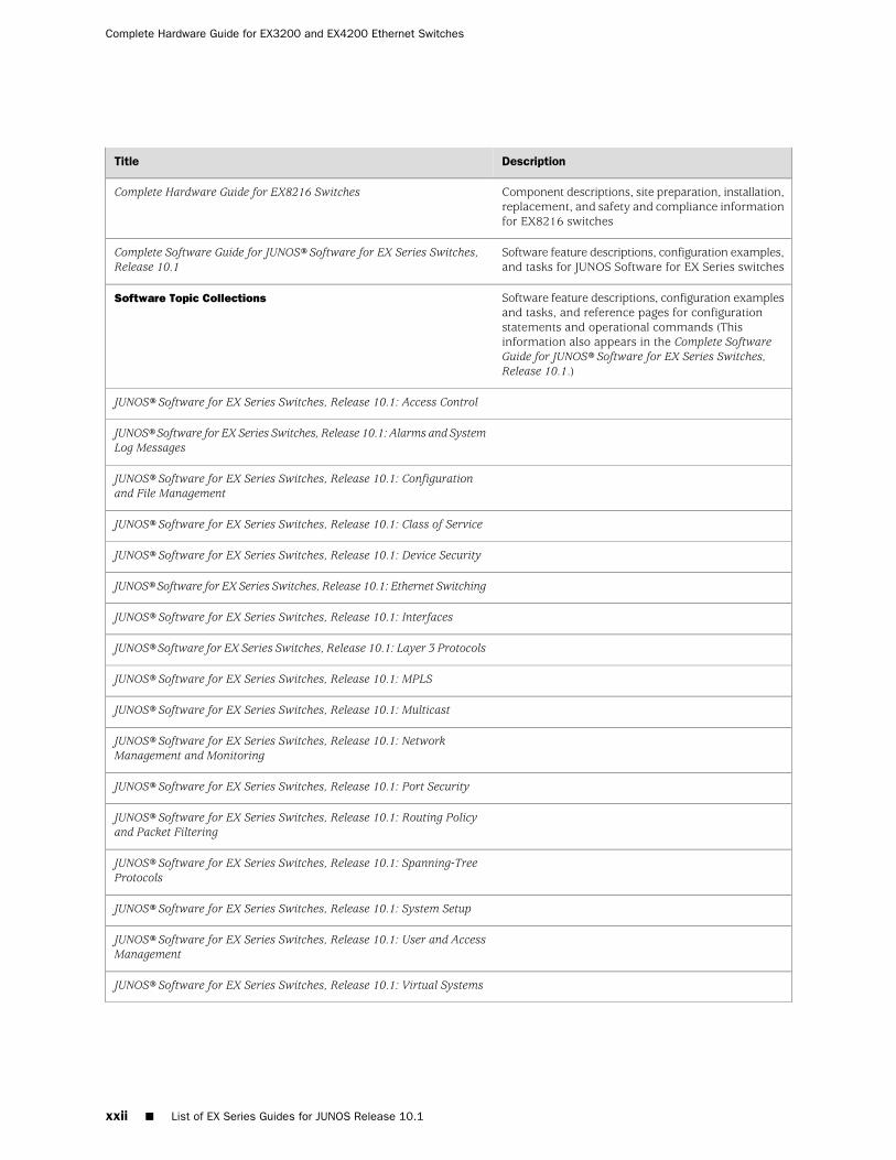
Software feature descriptions, configuration examples,and tasks for JUNOS Software for EX Series switches
Complete Software Guide for JUNOS® Software for EX Series Switches,Release 10.1
Software feature descriptions, configuration examplesand tasks, and reference pages for configurationstatements and operational commands (Thisinformation also appears in the Complete SoftwareGuide for JUNOS® Software for EX Series Switches,Release 10.1.)
Software Topic Collections
JUNOS® Software for EX Series Switches, Release 10.1: Access Control
JUNOS® Software for EX Series Switches, Release 10.1: Alarms and SystemLog Messages
JUNOS® Software for EX Series Switches, Release 10.1: Configurationand File Management
JUNOS® Software for EX Series Switches, Release 10.1: Class of Service
JUNOS® Software for EX Series Switches, Release 10.1: Device Security
JUNOS® Software for EX Series Switches, Release 10.1: Ethernet Switching
JUNOS® Software for EX Series Switches, Release 10.1: Interfaces
JUNOS® Software for EX Series Switches, Release 10.1: Layer 3 Protocols
JUNOS® Software for EX Series Switches, Release 10.1: MPLS
JUNOS® Software for EX Series Switches, Release 10.1: Multicast
JUNOS® Software for EX Series Switches, Release 10.1: NetworkManagement and Monitoring
JUNOS® Software for EX Series Switches, Release 10.1: Port Security
JUNOS® Software for EX Series Switches, Release 10.1: Routing Policyand Packet Filtering
JUNOS® Software for EX Series Switches, Release 10.1: Spanning-TreeProtocols
JUNOS® Software for EX Series Switches, Release 10.1: System Setup
JUNOS® Software for EX Series Switches, Release 10.1: User and AccessManagement
JUNOS® Software for EX Series Switches, Release 10.1: Virtual Systems
xxii ■ List of EX Series Guides for JUNOS Release 10.1
Complete Hardware Guide for EX3200 and EX4200 Ethernet Switches
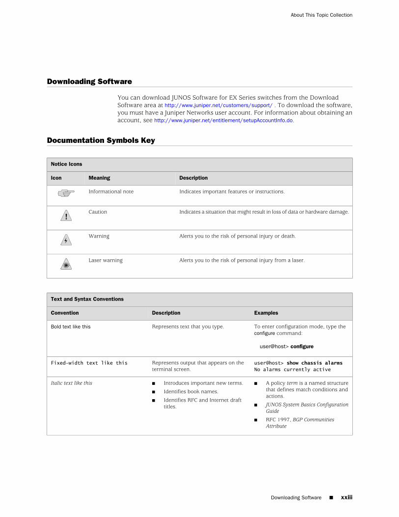
Downloading Software
You can download JUNOS Software for EX Series switches from the DownloadSoftware area at http://www.juniper.net/customers/support/ . To download the software,you must have a Juniper Networks user account. For information about obtaining anaccount, see http://www.juniper.net/entitlement/setupAccountInfo.do.
Documentation Symbols Key
Notice Icons
DescriptionMeaningIcon
Indicates important features or instructions.Informational note
Indicates a situation that might result in loss of data or hardware damage.Caution
Alerts you to the risk of personal injury or death.Warning
Alerts you to the risk of personal injury from a laser.Laser warning
Text and Syntax Conventions
ExamplesDescriptionConvention
To enter configuration mode, type theconfigure command:
user@host> configure
Represents text that you type.Bold text like this
user@host> show chassis alarmsNo alarms currently active
Represents output that appears on theterminal screen.
Fixed-width text like this
■ A policy term is a named structurethat defines match conditions andactions.
■ JUNOS System Basics ConfigurationGuide
■ RFC 1997, BGP CommunitiesAttribute
■ Introduces important new terms.
■ Identifies book names.
■ Identifies RFC and Internet drafttitles.
Italic text like this
Downloading Software ■ xxiii
About This Topic Collection
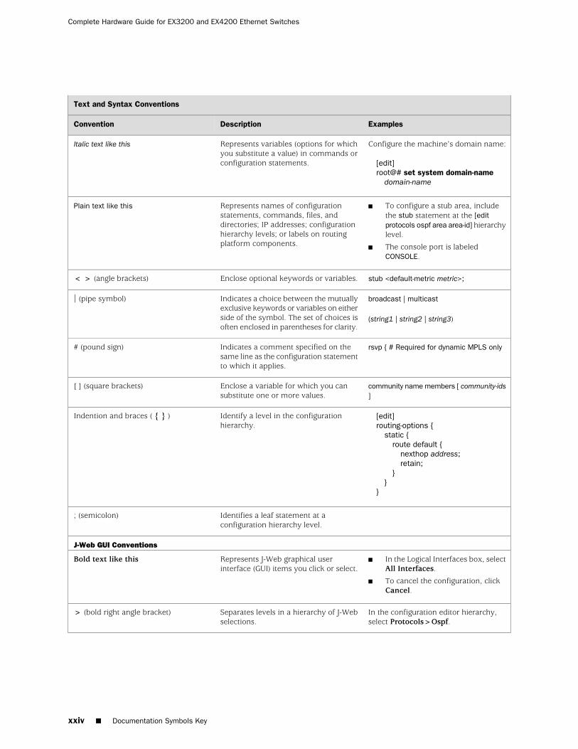
Text and Syntax Conventions
ExamplesDescriptionConvention
Configure the machine’s domain name:
[edit]root@# set system domain-name
domain-name
Represents variables (options for whichyou substitute a value) in commands orconfiguration statements.
Italic text like this
■ To configure a stub area, includethe stub statement at the [editprotocols ospf area area-id] hierarchylevel.
■ The console port is labeledCONSOLE.
Represents names of configurationstatements, commands, files, anddirectories; IP addresses; configurationhierarchy levels; or labels on routingplatform components.
Plain text like this
stub <default-metric metric>;Enclose optional keywords or variables.< > (angle brackets)
broadcast | multicast
(string1 | string2 | string3)
Indicates a choice between the mutuallyexclusive keywords or variables on eitherside of the symbol. The set of choices isoften enclosed in parentheses for clarity.
| (pipe symbol)
rsvp { # Required for dynamic MPLS onlyIndicates a comment specified on thesame line as the configuration statementto which it applies.
# (pound sign)
community name members [ community-ids]
Enclose a variable for which you cansubstitute one or more values.
[ ] (square brackets)
[edit]routing-options {
static {route default {
nexthop address;retain;
}}
}
Identify a level in the configurationhierarchy.
Indention and braces ( { } )
Identifies a leaf statement at aconfiguration hierarchy level.
; (semicolon)
J-Web GUI Conventions
■ In the Logical Interfaces box, selectAll Interfaces.
■ To cancel the configuration, clickCancel.
Represents J-Web graphical userinterface (GUI) items you click or select.
Bold text like this
In the configuration editor hierarchy,select Protocols>Ospf.
Separates levels in a hierarchy of J-Webselections.
> (bold right angle bracket)
xxiv ■ Documentation Symbols Key
Complete Hardware Guide for EX3200 and EX4200 Ethernet Switches
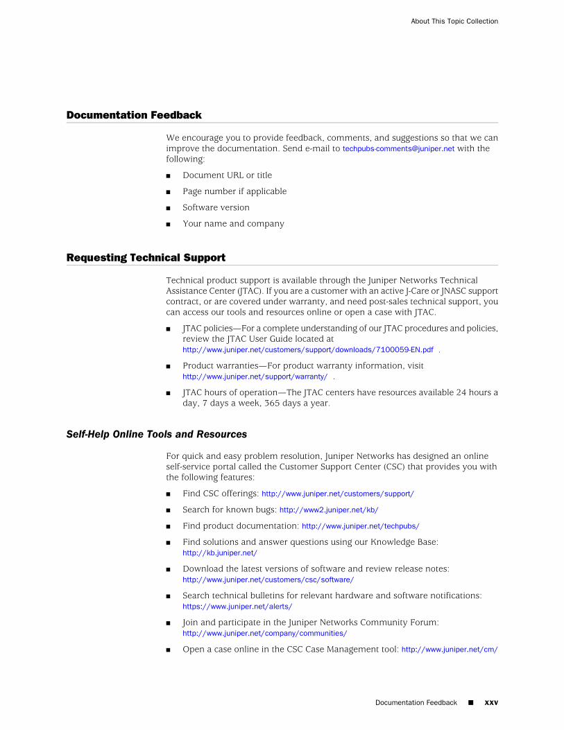
Documentation Feedback
We encourage you to provide feedback, comments, and suggestions so that we canimprove the documentation. Send e-mail to [email protected] with thefollowing:
■ Document URL or title
■ Page number if applicable
■ Software version
■ Your name and company
Requesting Technical Support
Technical product support is available through the Juniper Networks TechnicalAssistance Center (JTAC). If you are a customer with an active J-Care or JNASC supportcontract, or are covered under warranty, and need post-sales technical support, youcan access our tools and resources online or open a case with JTAC.
■ JTAC policies—For a complete understanding of our JTAC procedures and policies,review the JTAC User Guide located athttp://www.juniper.net/customers/support/downloads/7100059-EN.pdf .
■ Product warranties—For product warranty information, visithttp://www.juniper.net/support/warranty/ .
■ JTAC hours of operation—The JTAC centers have resources available 24 hours aday, 7 days a week, 365 days a year.
Self-Help Online Tools and Resources
For quick and easy problem resolution, Juniper Networks has designed an onlineself-service portal called the Customer Support Center (CSC) that provides you withthe following features:
■ Find CSC offerings: http://www.juniper.net/customers/support/
■ Search for known bugs: http://www2.juniper.net/kb/
■ Find product documentation: http://www.juniper.net/techpubs/
■ Find solutions and answer questions using our Knowledge Base:http://kb.juniper.net/
■ Download the latest versions of software and review release notes:http://www.juniper.net/customers/csc/software/
■ Search technical bulletins for relevant hardware and software notifications:https://www.juniper.net/alerts/
■ Join and participate in the Juniper Networks Community Forum:http://www.juniper.net/company/communities/
■ Open a case online in the CSC Case Management tool: http://www.juniper.net/cm/
Documentation Feedback ■ xxv
About This Topic Collection

To verify service entitlement by product serial number, use our Serial NumberEntitlement (SNE) Tool: https://tools.juniper.net/SerialNumberEntitlementSearch/
Opening a Case with JTAC
You can open a case with JTAC on the Web or by telephone.
■ Use the Case Management tool in the CSC at http://www.juniper.net/cm/ .
■ Call 1-888-314-JTAC (1-888-314-5822 toll-free in the USA, Canada, and Mexico).
For international or direct-dial options in countries without toll-free numbers, seehttp://www.juniper.net/support/requesting support.html .
xxvi ■ Requesting Technical Support
Complete Hardware Guide for EX3200 and EX4200 Ethernet Switches

Part 1
Switch and Components Overview andSpecifications
■ EX3200 and EX4200 Switches Overview on page 3
■ Component Descriptions on page 13
■ Component Specifications on page 39
Switch and Components Overview and Specifications ■ 1

2 ■ Switch and Components Overview and Specifications
Complete Hardware Guide for EX3200 and EX4200 Ethernet Switches
Chapter 1
EX3200 and EX4200 Switches Overview
■ EX3200 and EX4200 Switches Hardware Overview on page 3
■ EX3200 Switch Models on page 6
■ EX4200 Switch Models on page 6
■ Chassis Physical Specifications for EX3200 and EX4200 Switches on page 7
■ Front Panel of an EX3200 Switch on page 8
■ Rear Panel of an EX3200 Switch on page 9
■ Front Panel of an EX4200 Switch on page 10
■ Rear Panel of an EX4200 Switch on page 11
EX3200 and EX4200 Switches Hardware Overview
Juniper Networks EX Series Ethernet Switches provide scalable connectivity for theenterprise market, including branch offices, campus locations, and data centers. Theswitches run under the Juniper Networks JUNOS Software, which provides Layer 2and Layer 3 switching, routing, and security services. The same JUNOS code basethat runs on EX Series switches also runs on all Juniper Networks J Series, M Series,MX Series, and T Series routers.
■ EX3200 and EX4200 Switch Types on page 3
■ EX3200 Switches on page 4
■ EX4200 Switches on page 4
■ Uplink Modules on page 5
■ Power over Ethernet (PoE) Ports on page 5
EX3200 and EX4200 Switch Types
Juniper Networks EX3200 and EX4200 Ethernet Switches are two closely relatedproduct lines:
■ EX3200 switches—Typically, you deploy these switches in branch environmentsor wiring closets.
■ EX4200 switches—You can interconnect EX4200 switches to form a VirtualChassis that operates as a single network entity. You can deploy these switcheswherever you need a high density of Gigabit Ethernet ports (24 to 480 ports),redundancy, or the ability to span a single switch across several wiring closets.
EX3200 and EX4200 Switches Hardware Overview ■ 3

Typically, EX4200 switches are used in large branch offices, campus wiringclosets, and top-of-rack locations in a data center.
Both lines have these features:
■ Run under JUNOS Software for EX Series switches
■ Have options of 24-port and 48-port models
■ Have options of full (all ports) or partial (8 ports) Power over Ethernet (PoE)capability
■ Have optional uplink modules that provide connection to distribution switches
EX3200 Switches
EX3200 switches provide connectivity for low-density environments. Typically, youdeploy these switches in branch environments or wiring closets where only oneswitch is required.
EX3200 switches are available in models with either 24 or 48 ports and with eitherall ports equipped for Power over Ethernet (PoE) or only 8 ports equipped for PoE.All models provide ports that have 10/100/1000Base-T Gigabit Ethernet connectorsand optional 1-gigabit small form-factor pluggable (SFP) transceivers, 10-gigabit smallform-factor pluggable (SFP+) transceivers, or 10-gigabit small form-factor pluggable(XFP) transceivers for use with fiber connections.
EX3200 switches include:
■ A field-replaceable power supply and an optional additional connection to anexternal power source.
■ A field-replaceable fan tray with single fan.
■ JUNOS Software with its modular design that enables failed system processes togracefully restart.
EX4200 Switches
EX4200 switches provide connectivity for medium- and high-density environmentsand scalability for growing networks. These switches can be deployed wherever youneed a high density of Gigabit Ethernet ports (24 to 480 ports) or redundancy.Typically, EX4200 switches are used in large branch offices, campus wiring closets,and data centers where they can be positioned as the top device in a rack to provideconnectivity for all the devices in the rack.
You can connect individual EX4200 switches together to form one unit and managethe unit as a single chassis, called a Virtual Chassis. You can add more memberswitches to the Virtual Chassis as needed, up to a total of 10 members.
EX4200 switches are available in models with 24 or 48 ports and with either all portsequipped for Power over Ethernet (PoE) or only 8 ports equipped for PoE. All modelsprovide ports that have 10/100/1000Base-T Gigabit Ethernet connectors and optional1-gigabit small form-factor pluggable (SFP) transceivers, 10-gigabit small form-factor
4 ■ EX3200 and EX4200 Switches Hardware Overview
Complete Hardware Guide for EX3200 and EX4200 Ethernet Switches
pluggable (SFP+) transceivers, or 10-gigabit small form-factor pluggable (XFP)transceivers for use with fiber connections.
Additionally, a 24-port model provides 100Base-FX/1000Base-X SFP ports. This modelis typically used as a small distribution switch.
All EX4200 switches have dedicated 64-Gbps Virtual Chassis ports that allow you toconnect the switches to each other. You can also use optional uplink module portsto connect members of a Virtual Chassis across multiple wiring closets.
To provide carrier-class reliability, EX4200 switches include:
■ Dual redundant power supplies that are field-replaceable and hot-swappable. Anoptional additional connection to an external power source is also available.
■ A field-replaceable fan tray with three fans. The switch remains operational if asingle fan fails.
■ Redundant Routing Engines in a Virtual Chassis configuration. This redundancyenables GRES (graceful Routing Engine switchover) and nonstop active routing.
■ JUNOS Software with its modular design that enables failed system processes togracefully restart.
Uplink Modules
Optional uplink modules are available for all EX3200 and EX4200 switches. Uplinkmodules provide two 10-gigabit small form-factor pluggable (XFP) transceivers, four1-gigabit small form-factor pluggable (SFP) transceivers, or two 10-gigabit smallform-factor pluggable (SFP+) transceivers. You can use XFP, SFP, or SFP+ ports toconnect an access switch to a distribution switch or to interconnect member switchesof a Virtual Chassis across multiple wiring closets.
Power over Ethernet (PoE) Ports
PoE ports provide electrical current to devices through the network cables so thatseparate power cords for devices such as IP phones, wireless access points, andsecurity cameras are unnecessary. Both the EX3200 and EX4200 switches haveoptions of full (all 24 or 48 ports) or partial (8 ports) PoE capability.
Full PoE models are primarily used in IP telephony environments. Partial PoE modelsare used in environments where, for example, only a few ports for wireless accesspoints or security cameras are required.
Related Topics ■ EX3200 Switch Models on page 6
■ EX4200 Switch Models on page 6
■ Field-Replaceable Units in EX3200 and EX4200 Switches on page 16
■ Site Preparation Checklist for EX3200 and EX4200 Switches on page 81
EX3200 and EX4200 Switches Hardware Overview ■ 5
Chapter 1: EX3200 and EX4200 Switches Overview
EX3200 Switch Models
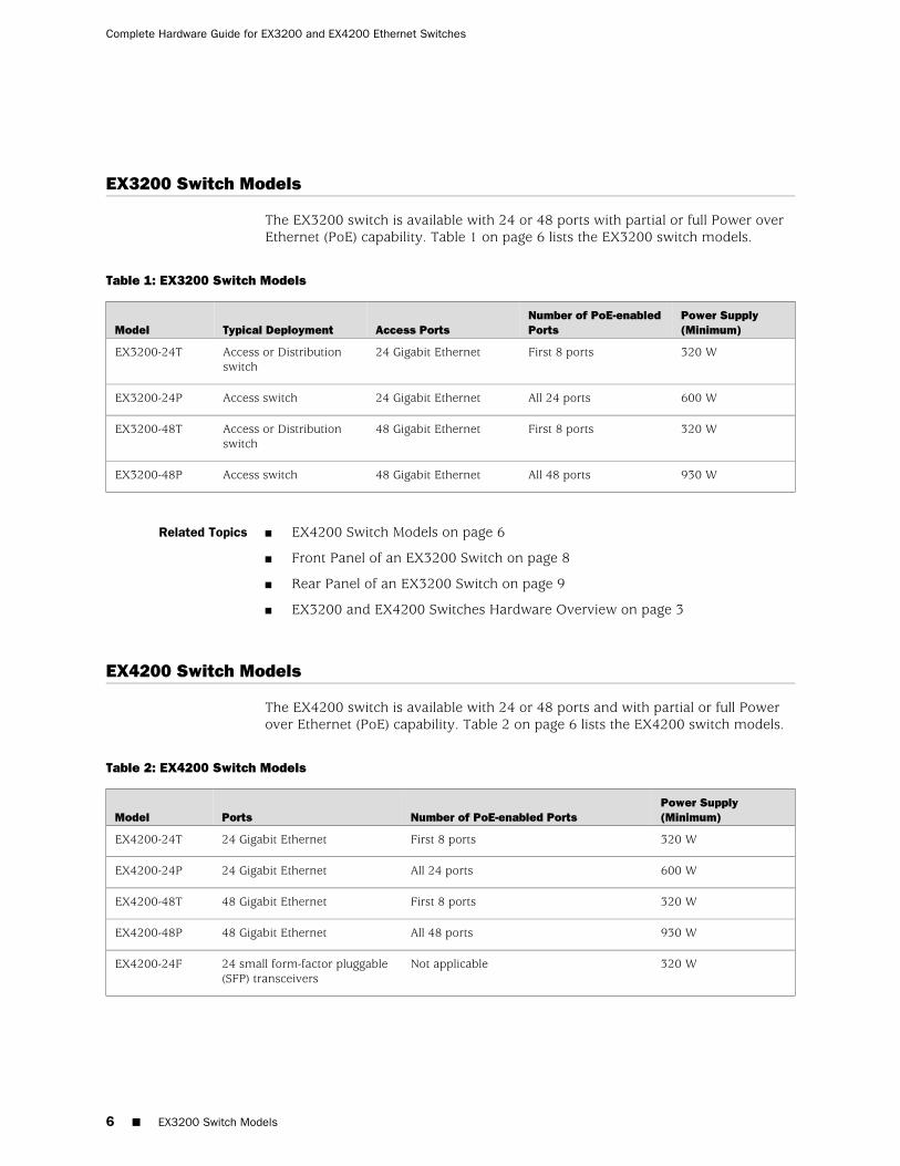
The EX3200 switch is available with 24 or 48 ports with partial or full Power overEthernet (PoE) capability. Table 1 on page 6 lists the EX3200 switch models.
Table 1: EX3200 Switch Models
Power Supply(Minimum)
Number of PoE-enabledPortsAccess PortsTypical DeploymentModel
320 WFirst 8 ports24 Gigabit EthernetAccess or Distributionswitch
EX3200-24T
600 WAll 24 ports24 Gigabit EthernetAccess switchEX3200-24P
320 WFirst 8 ports48 Gigabit EthernetAccess or Distributionswitch
EX3200-48T
930 WAll 48 ports48 Gigabit EthernetAccess switchEX3200-48P
Related Topics ■ EX4200 Switch Models on page 6
■ Front Panel of an EX3200 Switch on page 8
■ Rear Panel of an EX3200 Switch on page 9
■ EX3200 and EX4200 Switches Hardware Overview on page 3
EX4200 Switch Models
The EX4200 switch is available with 24 or 48 ports and with partial or full Powerover Ethernet (PoE) capability. Table 2 on page 6 lists the EX4200 switch models.
Table 2: EX4200 Switch Models
Power Supply(Minimum)Number of PoE-enabled PortsPortsModel
320 WFirst 8 ports24 Gigabit EthernetEX4200-24T
600 WAll 24 ports24 Gigabit EthernetEX4200-24P
320 WFirst 8 ports48 Gigabit EthernetEX4200-48T
930 WAll 48 ports48 Gigabit EthernetEX4200-48P
320 WNot applicable24 small form-factor pluggable(SFP) transceivers
EX4200-24F
6 ■ EX3200 Switch Models
Complete Hardware Guide for EX3200 and EX4200 Ethernet Switches
Related Topics ■ EX3200 Switch Models on page 6
■ Front Panel of an EX4200 Switch on page 10
■ Rear Panel of an EX4200 Switch on page 11
■ EX3200 and EX4200 Switches Hardware Overview on page 3
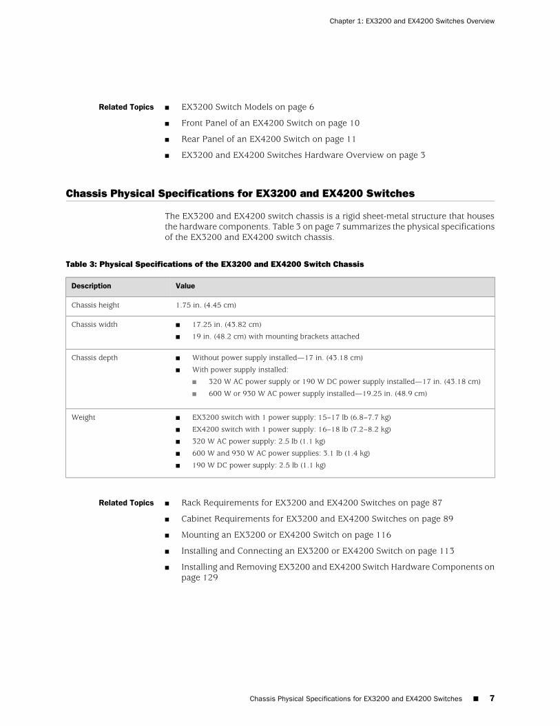
Chassis Physical Specifications for EX3200 and EX4200 Switches
The EX3200 and EX4200 switch chassis is a rigid sheet-metal structure that housesthe hardware components. Table 3 on page 7 summarizes the physical specificationsof the EX3200 and EX4200 switch chassis.
Table 3: Physical Specifications of the EX3200 and EX4200 Switch Chassis
ValueDescription
1.75 in. (4.45 cm)Chassis height
■ 17.25 in. (43.82 cm)
■ 19 in. (48.2 cm) with mounting brackets attached
Chassis width
■ Without power supply installed—17 in. (43.18 cm)
■ With power supply installed:
■ 320 W AC power supply or 190 W DC power supply installed—17 in. (43.18 cm)
■ 600 W or 930 W AC power supply installed—19.25 in. (48.9 cm)
Chassis depth
■ EX3200 switch with 1 power supply: 15–17 lb (6.8–7.7 kg)
■ EX4200 switch with 1 power supply: 16–18 lb (7.2–8.2 kg)
■ 320 W AC power supply: 2.5 lb (1.1 kg)
■ 600 W and 930 W AC power supplies: 3.1 lb (1.4 kg)
■ 190 W DC power supply: 2.5 lb (1.1 kg)
Weight
Related Topics ■ Rack Requirements for EX3200 and EX4200 Switches on page 87
■ Cabinet Requirements for EX3200 and EX4200 Switches on page 89
■ Mounting an EX3200 or EX4200 Switch on page 116
■ Installing and Connecting an EX3200 or EX4200 Switch on page 113
■ Installing and Removing EX3200 and EX4200 Switch Hardware Components onpage 129
Chassis Physical Specifications for EX3200 and EX4200 Switches ■ 7
Chapter 1: EX3200 and EX4200 Switches Overview
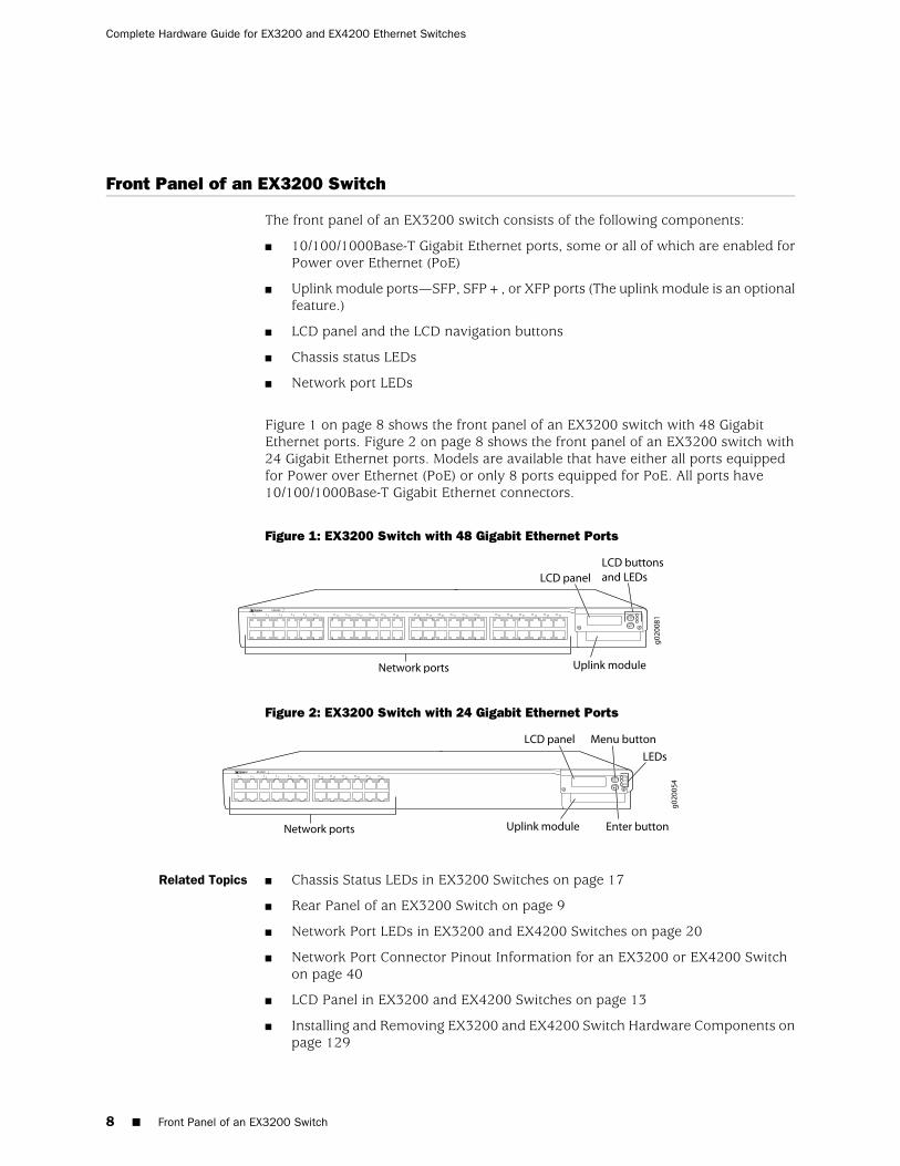
Front Panel of an EX3200 Switch
The front panel of an EX3200 switch consists of the following components:
■ 10/100/1000Base-T Gigabit Ethernet ports, some or all of which are enabled forPower over Ethernet (PoE)
■ Uplink module ports—SFP, SFP+, or XFP ports (The uplink module is an optionalfeature.)
■ LCD panel and the LCD navigation buttons
■ Chassis status LEDs
■ Network port LEDs
Figure 1 on page 8 shows the front panel of an EX3200 switch with 48 GigabitEthernet ports. Figure 2 on page 8 shows the front panel of an EX3200 switch with24 Gigabit Ethernet ports. Models are available that have either all ports equippedfor Power over Ethernet (PoE) or only 8 ports equipped for PoE. All ports have10/100/1000Base-T Gigabit Ethernet connectors.
Figure 1: EX3200 Switch with 48 Gigabit Ethernet Ports
Figure 2: EX3200 Switch with 24 Gigabit Ethernet Ports
Related Topics ■ Chassis Status LEDs in EX3200 Switches on page 17
■ Rear Panel of an EX3200 Switch on page 9
■ Network Port LEDs in EX3200 and EX4200 Switches on page 20
■ Network Port Connector Pinout Information for an EX3200 or EX4200 Switchon page 40
■ LCD Panel in EX3200 and EX4200 Switches on page 13
■ Installing and Removing EX3200 and EX4200 Switch Hardware Components onpage 129
8 ■ Front Panel of an EX3200 Switch
Complete Hardware Guide for EX3200 and EX4200 Ethernet Switches
■ Installing an Uplink Module in an EX3200 or EX4200 Switch on page 133
■ Removing an Uplink Module from an EX3200 or EX4200 Switch on page 175
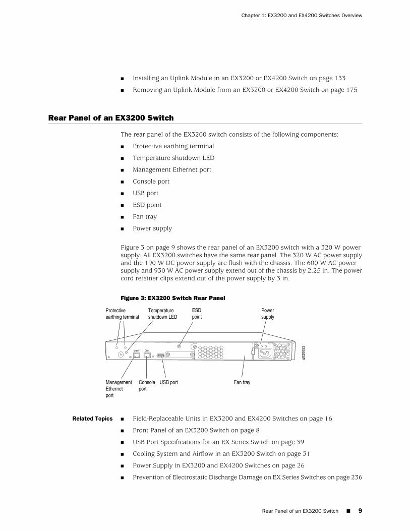
Rear Panel of an EX3200 Switch
The rear panel of the EX3200 switch consists of the following components:
■ Protective earthing terminal
■ Temperature shutdown LED
■ Management Ethernet port
■ Console port
■ USB port
■ ESD point
■ Fan tray
■ Power supply
Figure 3 on page 9 shows the rear panel of an EX3200 switch with a 320 W powersupply. All EX3200 switches have the same rear panel. The 320 W AC power supplyand the 190 W DC power supply are flush with the chassis. The 600 W AC powersupply and 930 W AC power supply extend out of the chassis by 2.25 in. The powercord retainer clips extend out of the power supply by 3 in.
Figure 3: EX3200 Switch Rear Panel
Related Topics ■ Field-Replaceable Units in EX3200 and EX4200 Switches on page 16
■ Front Panel of an EX3200 Switch on page 8
■ USB Port Specifications for an EX Series Switch on page 39
■ Cooling System and Airflow in an EX3200 Switch on page 31
■ Power Supply in EX3200 and EX4200 Switches on page 26
■ Prevention of Electrostatic Discharge Damage on EX Series Switches on page 236
Rear Panel of an EX3200 Switch ■ 9
Chapter 1: EX3200 and EX4200 Switches Overview
■ Connecting Earth Ground to an EX Series Switch on page 141
■ Installing and Removing EX3200 and EX4200 Switch Hardware Components onpage 129
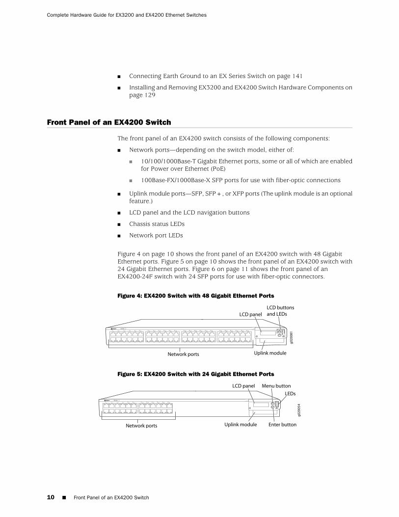
Front Panel of an EX4200 Switch
The front panel of an EX4200 switch consists of the following components:
■ Network ports—depending on the switch model, either of:
■ 10/100/1000Base-T Gigabit Ethernet ports, some or all of which are enabledfor Power over Ethernet (PoE)
■ 100Base-FX/1000Base-X SFP ports for use with fiber-optic connections
■ Uplink module ports—SFP, SFP+, or XFP ports (The uplink module is an optionalfeature.)
■ LCD panel and the LCD navigation buttons
■ Chassis status LEDs
■ Network port LEDs
Figure 4 on page 10 shows the front panel of an EX4200 switch with 48 GigabitEthernet ports. Figure 5 on page 10 shows the front panel of an EX4200 switch with24 Gigabit Ethernet ports. Figure 6 on page 11 shows the front panel of anEX4200-24F switch with 24 SFP ports for use with fiber-optic connectors.
Figure 4: EX4200 Switch with 48 Gigabit Ethernet Ports
Figure 5: EX4200 Switch with 24 Gigabit Ethernet Ports
10 ■ Front Panel of an EX4200 Switch
Complete Hardware Guide for EX3200 and EX4200 Ethernet Switches
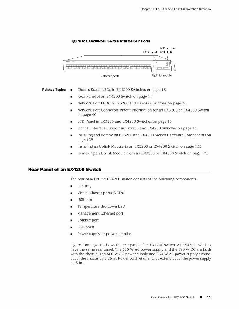
Figure 6: EX4200-24F Switch with 24 SFP Ports
Related Topics ■ Chassis Status LEDs in EX4200 Switches on page 18
■ Rear Panel of an EX4200 Switch on page 11
■ Network Port LEDs in EX3200 and EX4200 Switches on page 20
■ Network Port Connector Pinout Information for an EX3200 or EX4200 Switchon page 40
■ LCD Panel in EX3200 and EX4200 Switches on page 13
■ Optical Interface Support in EX3200 and EX4200 Switches on page 43
■ Installing and Removing EX3200 and EX4200 Switch Hardware Components onpage 129
■ Installing an Uplink Module in an EX3200 or EX4200 Switch on page 133
■ Removing an Uplink Module from an EX3200 or EX4200 Switch on page 175
Rear Panel of an EX4200 Switch
The rear panel of the EX4200 switch consists of the following components:
■ Fan tray
■ Virtual Chassis ports (VCPs)
■ USB port
■ Temperature shutdown LED
■ Management Ethernet port
■ Console port
■ ESD point
■ Power supply or power supplies
Figure 7 on page 12 shows the rear panel of an EX4200 switch. All EX4200 switcheshave the same rear panel. The 320 W AC power supply and the 190 W DC are flushwith the chassis. The 600 W AC power supply and 930 W AC power supply extendout of the chassis by 2.25 in. Power cord retainer clips extend out of the power supplyby 3 in.
Rear Panel of an EX4200 Switch ■ 11
Chapter 1: EX3200 and EX4200 Switches Overview
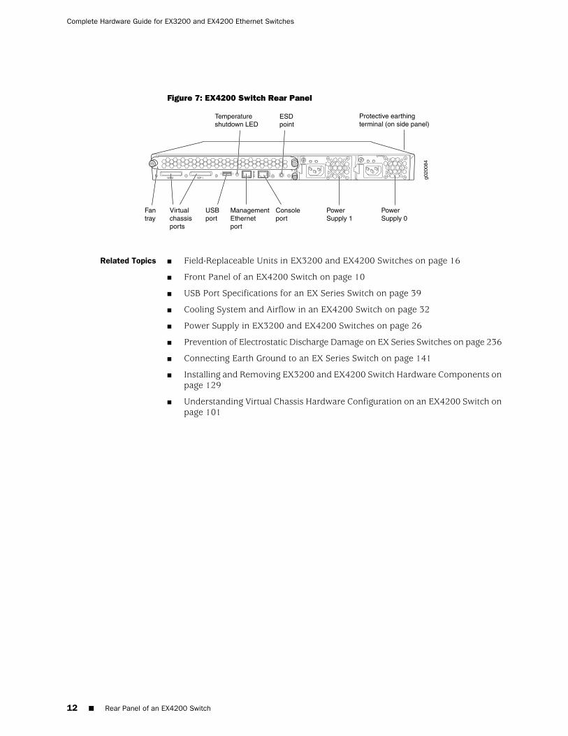
Figure 7: EX4200 Switch Rear Panel
g020
084
Virtualchassisports
USBport
ManagementEthernetport
Fantray
Consoleport
PowerSupply 1
PowerSupply 0
Protective earthingterminal (on side panel)
ESDpoint
Temperatureshutdown LED
Related Topics ■ Field-Replaceable Units in EX3200 and EX4200 Switches on page 16
■ Front Panel of an EX4200 Switch on page 10
■ USB Port Specifications for an EX Series Switch on page 39
■ Cooling System and Airflow in an EX4200 Switch on page 32
■ Power Supply in EX3200 and EX4200 Switches on page 26
■ Prevention of Electrostatic Discharge Damage on EX Series Switches on page 236
■ Connecting Earth Ground to an EX Series Switch on page 141
■ Installing and Removing EX3200 and EX4200 Switch Hardware Components onpage 129
■ Understanding Virtual Chassis Hardware Configuration on an EX4200 Switch onpage 101
12 ■ Rear Panel of an EX4200 Switch
Complete Hardware Guide for EX3200 and EX4200 Ethernet Switches
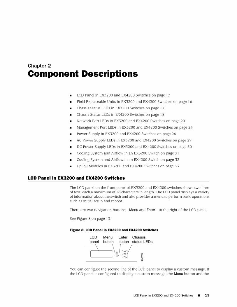
Chapter 2
Component Descriptions
■ LCD Panel in EX3200 and EX4200 Switches on page 13
■ Field-Replaceable Units in EX3200 and EX4200 Switches on page 16
■ Chassis Status LEDs in EX3200 Switches on page 17
■ Chassis Status LEDs in EX4200 Switches on page 18
■ Network Port LEDs in EX3200 and EX4200 Switches on page 20
■ Management Port LEDs in EX3200 and EX4200 Switches on page 24
■ Power Supply in EX3200 and EX4200 Switches on page 26
■ AC Power Supply LEDs in EX3200 and EX4200 Switches on page 29
■ DC Power Supply LEDs in EX3200 and EX4200 Switches on page 30
■ Cooling System and Airflow in an EX3200 Switch on page 31
■ Cooling System and Airflow in an EX4200 Switch on page 32
■ Uplink Modules in EX3200 and EX4200 Switches on page 33
LCD Panel in EX3200 and EX4200 Switches
The LCD panel on the front panel of EX3200 and EX4200 switches shows two linesof text, each a maximum of 16 characters in length. The LCD panel displays a varietyof information about the switch and also provides a menu to perform basic operationssuch as initial setup and reboot.
There are two navigation buttons—Menu and Enter—to the right of the LCD panel.
See Figure 8 on page 13.
Figure 8: LCD Panel in EX3200 and EX4200 Switches
You can configure the second line of the LCD panel to display a custom message. Ifthe LCD panel is configured to display a custom message, the Menu button and the
LCD Panel in EX3200 and EX4200 Switches ■ 13
Enter button are disabled. See “Configuring the LCD Panel Display on EX SeriesSwitches (CLI Procedure)” on page 166.
The LCD panel has a backlight. If the LCD panel is idle for 60 seconds, the backlightturns off. You can turn on the backlight by pressing the Menu or Enter button once.After turning on the backlight, you can toggle between the LCD panel menus bypressing the Menu button and navigate through the menu options by pressing theEnter button.
NOTE: The chassis viewer in the J-Web interface also displays the LCD panel. Fromthe J-Web interface, you can view real-time status information in the LCD panel. SeeDashboard for EX Series Switches.
This topic describes:
■ LCD Panel Modes on page 14
■ LCD Panel Menus on page 15
LCD Panel Modes
The LCD panel operates in four modes: boot, idle, status, and maintenance.
The LCD panel operates in boot mode during switch reboot. The boot mode displaysthe key milestones in the switch boot process. The boot mode does not have anymenu options. After the boot process is complete, the LCD panel automatically revertsto the Idle menu.
In an EX3200 switch, the first line of the LCD panel displays the hostname.
In an EX4200 switch that is not a member of a Virtual Chassis, the first line of theLCD panel displays the slot number, the role of the switch, and hostname. For astandalone EX4200 switch, the slot number is always 00 and the role is always RE(for master).
In an EX4200 switch that is a member of a Virtual Chassis, the first line of the LCDpanel displays:
■ The slot number (the member ID for the Virtual Chassis member)
■ Role of the switch in a Virtual Chassis (RE for master, BK for backup, and LC forlinecard member)
■ Hostname
In the idle mode, the second line displays the mode of the network ports’ Status LEDand the number of chassis alarms. The number of alarms is updated every second.
In the status mode, the second line displays:
■ Virtual Chassis port (VCP) status (for an EX4200 switch that is a member of aVirtual Chassis)
■ Status of the power supply
14 ■ LCD Panel in EX3200 and EX4200 Switches
Complete Hardware Guide for EX3200 and EX4200 Ethernet Switches
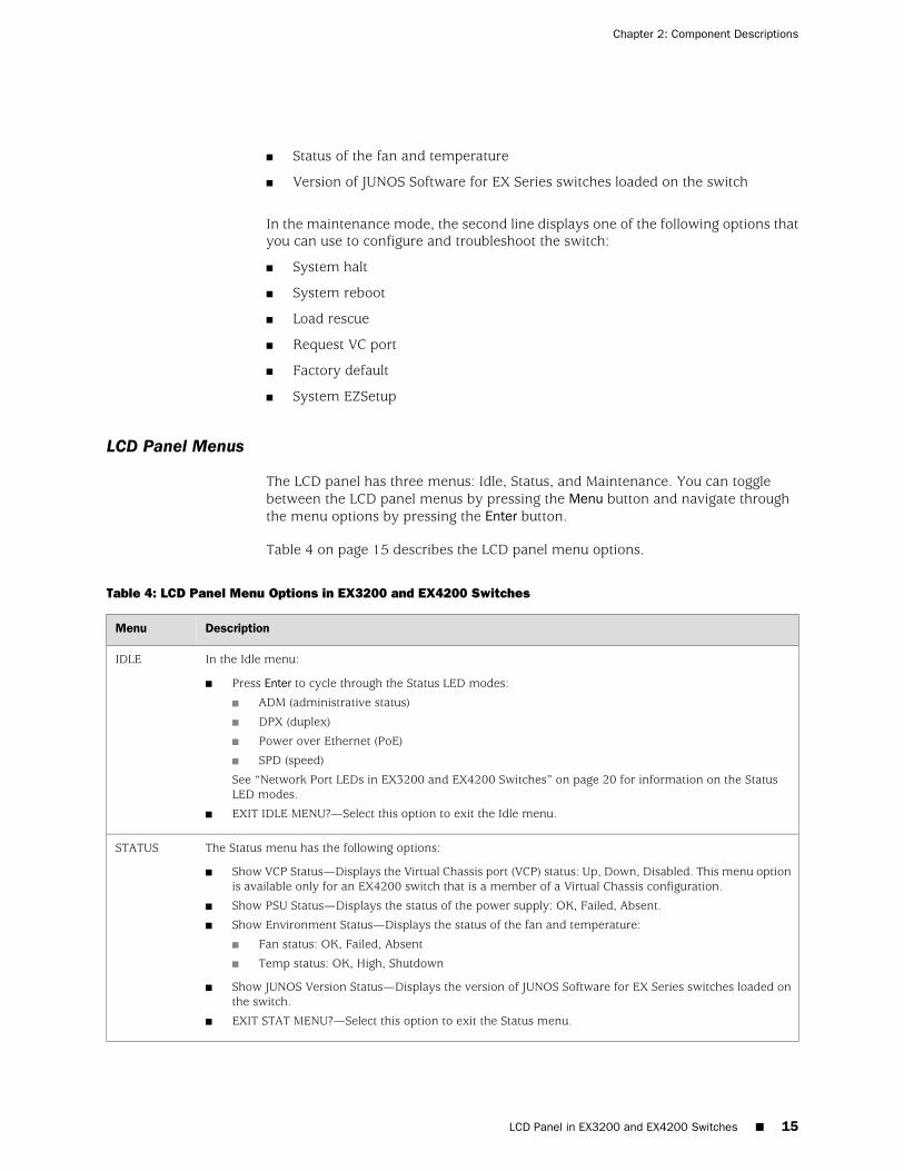
■ Status of the fan and temperature
■ Version of JUNOS Software for EX Series switches loaded on the switch
In the maintenance mode, the second line displays one of the following options thatyou can use to configure and troubleshoot the switch:
■ System halt
■ System reboot
■ Load rescue
■ Request VC port
■ Factory default
■ System EZSetup
LCD Panel Menus
The LCD panel has three menus: Idle, Status, and Maintenance. You can togglebetween the LCD panel menus by pressing the Menu button and navigate throughthe menu options by pressing the Enter button.
Table 4 on page 15 describes the LCD panel menu options.
Table 4: LCD Panel Menu Options in EX3200 and EX4200 Switches
DescriptionMenu
In the Idle menu:
■ Press Enter to cycle through the Status LED modes:
■ ADM (administrative status)
■ DPX (duplex)
■ Power over Ethernet (PoE)
■ SPD (speed)
See “Network Port LEDs in EX3200 and EX4200 Switches” on page 20 for information on the StatusLED modes.
■ EXIT IDLE MENU?—Select this option to exit the Idle menu.
IDLE
The Status menu has the following options:
■ Show VCP Status—Displays the Virtual Chassis port (VCP) status: Up, Down, Disabled. This menu optionis available only for an EX4200 switch that is a member of a Virtual Chassis configuration.
■ Show PSU Status—Displays the status of the power supply: OK, Failed, Absent.
■ Show Environment Status—Displays the status of the fan and temperature:
■ Fan status: OK, Failed, Absent
■ Temp status: OK, High, Shutdown
■ Show JUNOS Version Status—Displays the version of JUNOS Software for EX Series switches loaded onthe switch.
■ EXIT STAT MENU?—Select this option to exit the Status menu.
STATUS
LCD Panel in EX3200 and EX4200 Switches ■ 15
Chapter 2: Component Descriptions
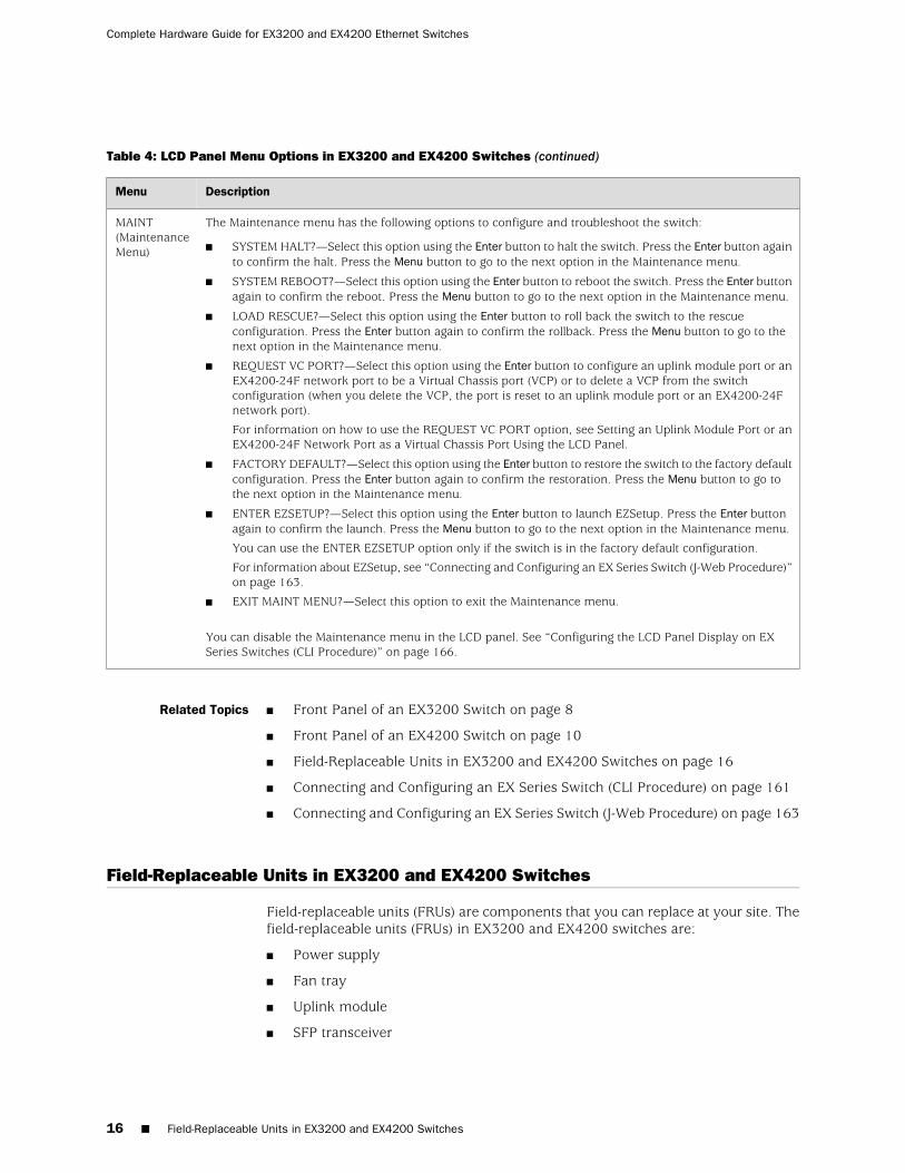
Table 4: LCD Panel Menu Options in EX3200 and EX4200 Switches (continued)
DescriptionMenu
The Maintenance menu has the following options to configure and troubleshoot the switch:
■ SYSTEM HALT?—Select this option using the Enter button to halt the switch. Press the Enter button againto confirm the halt. Press the Menu button to go to the next option in the Maintenance menu.
■ SYSTEM REBOOT?—Select this option using the Enter button to reboot the switch. Press the Enter buttonagain to confirm the reboot. Press the Menu button to go to the next option in the Maintenance menu.
■ LOAD RESCUE?—Select this option using the Enter button to roll back the switch to the rescueconfiguration. Press the Enter button again to confirm the rollback. Press the Menu button to go to thenext option in the Maintenance menu.
■ REQUEST VC PORT?—Select this option using the Enter button to configure an uplink module port or anEX4200-24F network port to be a Virtual Chassis port (VCP) or to delete a VCP from the switchconfiguration (when you delete the VCP, the port is reset to an uplink module port or an EX4200-24Fnetwork port).
For information on how to use the REQUEST VC PORT option, see Setting an Uplink Module Port or anEX4200-24F Network Port as a Virtual Chassis Port Using the LCD Panel.
■ FACTORY DEFAULT?—Select this option using the Enter button to restore the switch to the factory defaultconfiguration. Press the Enter button again to confirm the restoration. Press the Menu button to go tothe next option in the Maintenance menu.
■ ENTER EZSETUP?—Select this option using the Enter button to launch EZSetup. Press the Enter buttonagain to confirm the launch. Press the Menu button to go to the next option in the Maintenance menu.
You can use the ENTER EZSETUP option only if the switch is in the factory default configuration.
For information about EZSetup, see “Connecting and Configuring an EX Series Switch (J-Web Procedure)”on page 163.
■ EXIT MAINT MENU?—Select this option to exit the Maintenance menu.
You can disable the Maintenance menu in the LCD panel. See “Configuring the LCD Panel Display on EXSeries Switches (CLI Procedure)” on page 166.
MAINT(MaintenanceMenu)
Related Topics ■ Front Panel of an EX3200 Switch on page 8
■ Front Panel of an EX4200 Switch on page 10
■ Field-Replaceable Units in EX3200 and EX4200 Switches on page 16
■ Connecting and Configuring an EX Series Switch (CLI Procedure) on page 161
■ Connecting and Configuring an EX Series Switch (J-Web Procedure) on page 163
Field-Replaceable Units in EX3200 and EX4200 Switches
Field-replaceable units (FRUs) are components that you can replace at your site. Thefield-replaceable units (FRUs) in EX3200 and EX4200 switches are:
■ Power supply
■ Fan tray
■ Uplink module
■ SFP transceiver
16 ■ Field-Replaceable Units in EX3200 and EX4200 Switches
Complete Hardware Guide for EX3200 and EX4200 Ethernet Switches
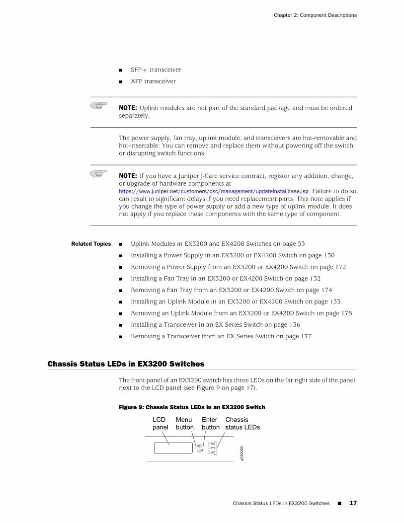
■ SFP+ transceiver
■ XFP transceiver
NOTE: Uplink modules are not part of the standard package and must be orderedseparately.
The power supply, fan tray, uplink module, and transceivers are hot-removable andhot-insertable: You can remove and replace them without powering off the switchor disrupting switch functions.
NOTE: If you have a Juniper J-Care service contract, register any addition, change,or upgrade of hardware components athttps://www.juniper.net/customers/csc/management/updateinstallbase.jsp. Failure to do socan result in significant delays if you need replacement parts. This note applies ifyou change the type of power supply or add a new type of uplink module. It doesnot apply if you replace these components with the same type of component.
Related Topics ■ Uplink Modules in EX3200 and EX4200 Switches on page 33
■ Installing a Power Supply in an EX3200 or EX4200 Switch on page 130
■ Removing a Power Supply from an EX3200 or EX4200 Switch on page 172
■ Installing a Fan Tray in an EX3200 or EX4200 Switch on page 132
■ Removing a Fan Tray from an EX3200 or EX4200 Switch on page 174
■ Installing an Uplink Module in an EX3200 or EX4200 Switch on page 133
■ Removing an Uplink Module from an EX3200 or EX4200 Switch on page 175
■ Installing a Transceiver in an EX Series Switch on page 136
■ Removing a Transceiver from an EX Series Switch on page 177
Chassis Status LEDs in EX3200 Switches
The front panel of an EX3200 switch has three LEDs on the far right side of the panel,next to the LCD panel (see Figure 9 on page 17).
Figure 9: Chassis Status LEDs in an EX3200 Switch
Chassis Status LEDs in EX3200 Switches ■ 17
Chapter 2: Component Descriptions
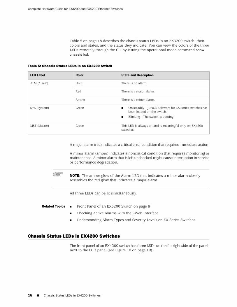
Table 5 on page 18 describes the chassis status LEDs in an EX3200 switch, theircolors and states, and the status they indicate. You can view the colors of the threeLEDs remotely through the CLI by issuing the operational mode command showchassis lcd.
Table 5: Chassis Status LEDs in an EX3200 Switch
State and DescriptionColorLED Label
There is no alarm.UnlitALM (Alarm)
There is a major alarm.Red
There is a minor alarm.Amber
■ On steadily—JUNOS Software for EX Series switches hasbeen loaded on the switch.
■ Blinking—The switch is booting.
GreenSYS (System)
This LED is always on and is meaningful only on EX4200switches.
GreenMST (Master)
A major alarm (red) indicates a critical error condition that requires immediate action.
A minor alarm (amber) indicates a noncritical condition that requires monitoring ormaintenance. A minor alarm that is left unchecked might cause interruption in serviceor performance degradation.
NOTE: The amber glow of the Alarm LED that indicates a minor alarm closelyresembles the red glow that indicates a major alarm.
All three LEDs can be lit simultaneously.
Related Topics Front Panel of an EX3200 Switch on page 8■
■ Checking Active Alarms with the J-Web Interface
■ Understanding Alarm Types and Severity Levels on EX Series Switches
Chassis Status LEDs in EX4200 Switches
The front panel of an EX4200 switch has three LEDs on the far right side of the panel,next to the LCD panel (see Figure 10 on page 19).
18 ■ Chassis Status LEDs in EX4200 Switches
Complete Hardware Guide for EX3200 and EX4200 Ethernet Switches
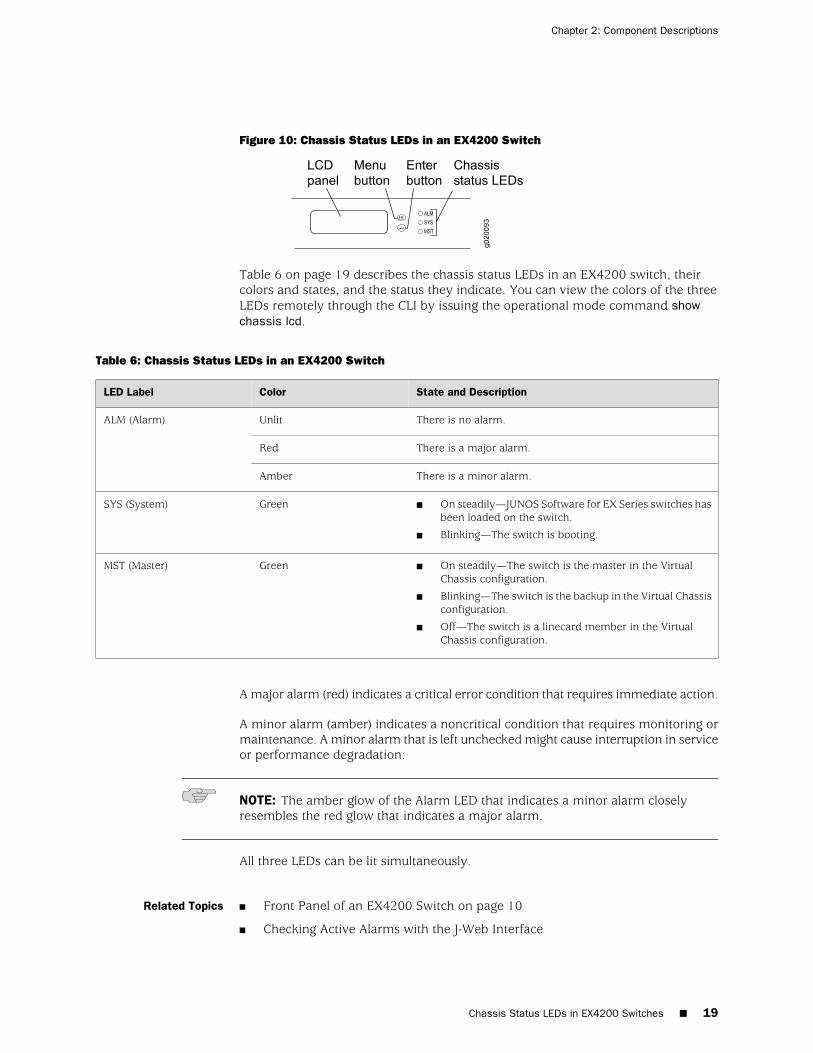
Figure 10: Chassis Status LEDs in an EX4200 Switch
Table 6 on page 19 describes the chassis status LEDs in an EX4200 switch, theircolors and states, and the status they indicate. You can view the colors of the threeLEDs remotely through the CLI by issuing the operational mode command showchassis lcd.
Table 6: Chassis Status LEDs in an EX4200 Switch
State and DescriptionColorLED Label
There is no alarm.UnlitALM (Alarm)
There is a major alarm.Red
There is a minor alarm.Amber
■ On steadily—JUNOS Software for EX Series switches hasbeen loaded on the switch.
■ Blinking—The switch is booting.
GreenSYS (System)
■ On steadily—The switch is the master in the VirtualChassis configuration.
■ Blinking—The switch is the backup in the Virtual Chassisconfiguration.
■ Off—The switch is a linecard member in the VirtualChassis configuration.
GreenMST (Master)
A major alarm (red) indicates a critical error condition that requires immediate action.
A minor alarm (amber) indicates a noncritical condition that requires monitoring ormaintenance. A minor alarm that is left unchecked might cause interruption in serviceor performance degradation.
NOTE: The amber glow of the Alarm LED that indicates a minor alarm closelyresembles the red glow that indicates a major alarm.
All three LEDs can be lit simultaneously.
Related Topics Front Panel of an EX4200 Switch on page 10■
■ Checking Active Alarms with the J-Web Interface
Chassis Status LEDs in EX4200 Switches ■ 19
Chapter 2: Component Descriptions
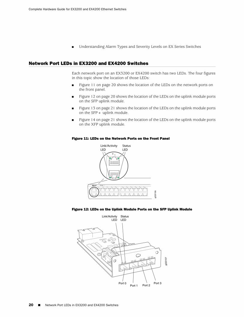
■ Understanding Alarm Types and Severity Levels on EX Series Switches
Network Port LEDs in EX3200 and EX4200 Switches
Each network port on an EX3200 or EX4200 switch has two LEDs. The four figuresin this topic show the location of those LEDs:
■ Figure 11 on page 20 shows the location of the LEDs on the network ports onthe front panel.
■ Figure 12 on page 20 shows the location of the LEDs on the uplink module portson the SFP uplink module.
■ Figure 13 on page 21 shows the location of the LEDs on the uplink module portson the SFP+ uplink module.
■ Figure 14 on page 21 shows the location of the LEDs on the uplink module portson the XFP uplink module.
Figure 11: LEDs on the Network Ports on the Front Panel
Figure 12: LEDs on the Uplink Module Ports on the SFP Uplink Module
20 ■ Network Port LEDs in EX3200 and EX4200 Switches
Complete Hardware Guide for EX3200 and EX4200 Ethernet Switches
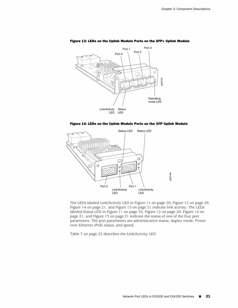
Figure 13: LEDs on the Uplink Module Ports on the SFP+ Uplink Module
Figure 14: LEDs on the Uplink Module Ports on the XFP Uplink Module
g020
108
Link/ActivityLED
Link/ActivityLED
Status LED Status LED
Port 0 Port 1
The LEDs labeled Link/Activity LED in Figure 11 on page 20, Figure 12 on page 20,Figure 14 on page 21, and Figure 13 on page 21 indicate link activity. The LEDslabeled Status LED in Figure 11 on page 20, Figure 12 on page 20, Figure 14 onpage 21, and Figure 13 on page 21 indicate the status of one of the four portparameters. The port parameters are administrative status, duplex mode, Powerover Ethernet (PoE) status, and speed.
Table 7 on page 22 describes the Link/Activity LED.
Network Port LEDs in EX3200 and EX4200 Switches ■ 21
Chapter 2: Component Descriptions

Table 7: Link/Activity LED on Network Ports in EX3200 and EX4200 Switches
State and DescriptionColorLED
■ Blinking—The port and the link are active, and there islink activity.
■ On steadily—The port and the link are active, but thereis no link activity.
■ Off—The port is not active.
GreenLink/Activity
Table 8 on page 23 describes the Status LED. From the Idle menu of the LCD, usethe Enter button on the LCD panel to toggle between the ADM, DPX, POE, and SPDindicators.
22 ■ Network Port LEDs in EX3200 and EX4200 Switches
Complete Hardware Guide for EX3200 and EX4200 Ethernet Switches
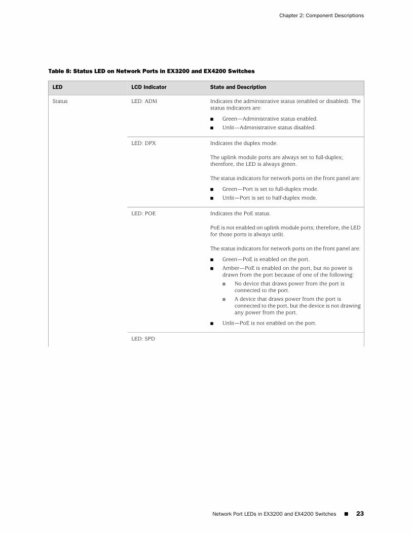
Table 8: Status LED on Network Ports in EX3200 and EX4200 Switches
State and DescriptionLCD IndicatorLED
Indicates the administrative status (enabled or disabled). Thestatus indicators are:
■ Green—Administrative status enabled.
■ Unlit—Administrative status disabled.
LED: ADMStatus
Indicates the duplex mode.
The uplink module ports are always set to full-duplex;therefore, the LED is always green.
The status indicators for network ports on the front panel are:
■ Green—Port is set to full-duplex mode.
■ Unlit—Port is set to half-duplex mode.
LED: DPX
Indicates the PoE status.
PoE is not enabled on uplink module ports; therefore, the LEDfor those ports is always unlit.
The status indicators for network ports on the front panel are:
■ Green—PoE is enabled on the port.
■ Amber—PoE is enabled on the port, but no power isdrawn from the port because of one of the following:
■ No device that draws power from the port isconnected to the port.
■ A device that draws power from the port isconnected to the port, but the device is not drawingany power from the port.
■ Unlit—PoE is not enabled on the port.
LED: POE
LED: SPD
Network Port LEDs in EX3200 and EX4200 Switches ■ 23
Chapter 2: Component Descriptions
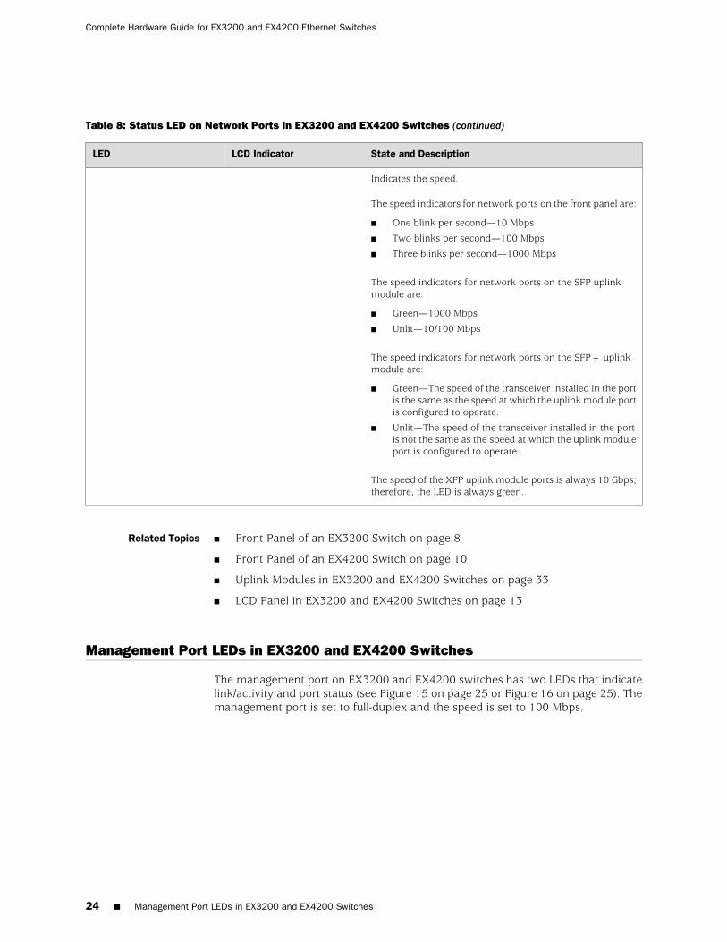
Table 8: Status LED on Network Ports in EX3200 and EX4200 Switches (continued)
State and DescriptionLCD IndicatorLED
Indicates the speed.
The speed indicators for network ports on the front panel are:
■ One blink per second—10 Mbps
■ Two blinks per second—100 Mbps
■ Three blinks per second—1000 Mbps
The speed indicators for network ports on the SFP uplinkmodule are:
■ Green—1000 Mbps
■ Unlit—10/100 Mbps
The speed indicators for network ports on the SFP+ uplinkmodule are:
■ Green—The speed of the transceiver installed in the portis the same as the speed at which the uplink module portis configured to operate.
■ Unlit—The speed of the transceiver installed in the portis not the same as the speed at which the uplink moduleport is configured to operate.
The speed of the XFP uplink module ports is always 10 Gbps;therefore, the LED is always green.
Related Topics ■ Front Panel of an EX3200 Switch on page 8
■ Front Panel of an EX4200 Switch on page 10
■ Uplink Modules in EX3200 and EX4200 Switches on page 33
■ LCD Panel in EX3200 and EX4200 Switches on page 13
Management Port LEDs in EX3200 and EX4200 Switches
The management port on EX3200 and EX4200 switches has two LEDs that indicatelink/activity and port status (see Figure 15 on page 25 or Figure 16 on page 25). Themanagement port is set to full-duplex and the speed is set to 100 Mbps.
24 ■ Management Port LEDs in EX3200 and EX4200 Switches
Complete Hardware Guide for EX3200 and EX4200 Ethernet Switches
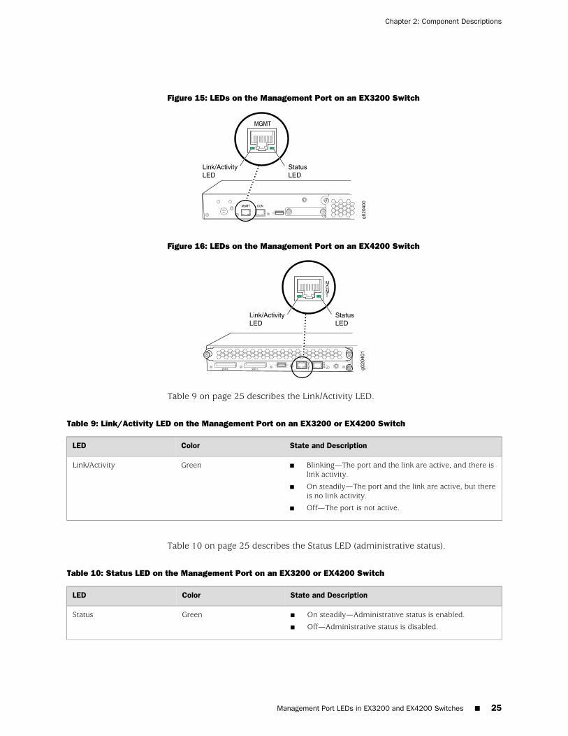
Figure 15: LEDs on the Management Port on an EX3200 Switch
Figure 16: LEDs on the Management Port on an EX4200 Switch
Table 9 on page 25 describes the Link/Activity LED.
Table 9: Link/Activity LED on the Management Port on an EX3200 or EX4200 Switch
State and DescriptionColorLED
■ Blinking—The port and the link are active, and there islink activity.
■ On steadily—The port and the link are active, but thereis no link activity.
■ Off—The port is not active.
GreenLink/Activity
Table 10 on page 25 describes the Status LED (administrative status).
Table 10: Status LED on the Management Port on an EX3200 or EX4200 Switch
State and DescriptionColorLED
■ On steadily—Administrative status is enabled.
■ Off—Administrative status is disabled.
GreenStatus
Management Port LEDs in EX3200 and EX4200 Switches ■ 25
Chapter 2: Component Descriptions
Related Topics See Rear Panel of an EX3200 Switch on page 9 for port location.■
■ See Rear Panel of an EX4200 Switch on page 11 for port location.
■ Connecting an EX Series Switch to a Network for Out-of-Band Management onpage 152
Power Supply in EX3200 and EX4200 Switches
The power supply in EX3200 and EX4200 switches (see Figure 17 on page 27, Figure18 on page 27 and Figure 19 on page 27) is a hot-removable and hot-insertablefield-replaceable unit (FRU) that you can install on the rear panel without poweringoff the switch or disrupting the switching function. EX4200 switches have an internalredundant power supply, making the power supply in EX4200 switches fullyredundant. The power supply in EX3200 switches is not redundant.
EX3200 and EX4200 switches use power that provides two DC output voltages: 12 Vfor system and logic power and 48–51 V (or higher, to compensate for voltage dropsalong the path from the power supplies to the RJ-45 connector) for PoE ports.
The AC power supply in EX3200 and EX4200 switches is available in 320 W, 600 W,and 930 W models. The exterior of the 600 W model is identical to that of the 930 Wmodel. The 320 W power supply is flush with the chassis. The 600 W power supplyand 930 W power supply extend out of the chassis by 2.25 in. The power cord retainerclips extend out of the power supply by 3 in. The number of ports on which PoE isenabled determines the minimum power requirements.
The DC power supply in EX3200 and EX4200 switches is available in a 190 W model,with dual input feeds for power resiliency. You can install redundant DC powersupplies in an EX4200 switch to achieve both power supply and power feed resiliency.
NOTE: The DC power supply in EX3200 and EX4200 switches does not supportPower over Ethernet (PoE); you can use either an external power injector or an ACpower supply to supply power to PoE devices that you connect to the switch.
NOTE: The DC power supply in EX3200 and EX4200 switches has four terminalslabeled A+, B+, A–, and B– (see Figure 19 on page 27) for connecting DC powersource cables labeled positive (+) and negative (–). The DC power supplies for EX3200and EX4200 switches are shipped with jumpers from A+ input to B+ input tiedtogether and jumpers from A– input to B– input tied together.
NOTE: The A+ and B+ terminals are referred to as +RTN and A– and B– terminalsare referred to as –48 V in “DC Power Wiring Sequence Warning for EX SeriesSwitches” on page 245 and “DC Power Electrical Safety Guidelines for EX SeriesSwitches” on page 241.
26 ■ Power Supply in EX3200 and EX4200 Switches
Complete Hardware Guide for EX3200 and EX4200 Ethernet Switches
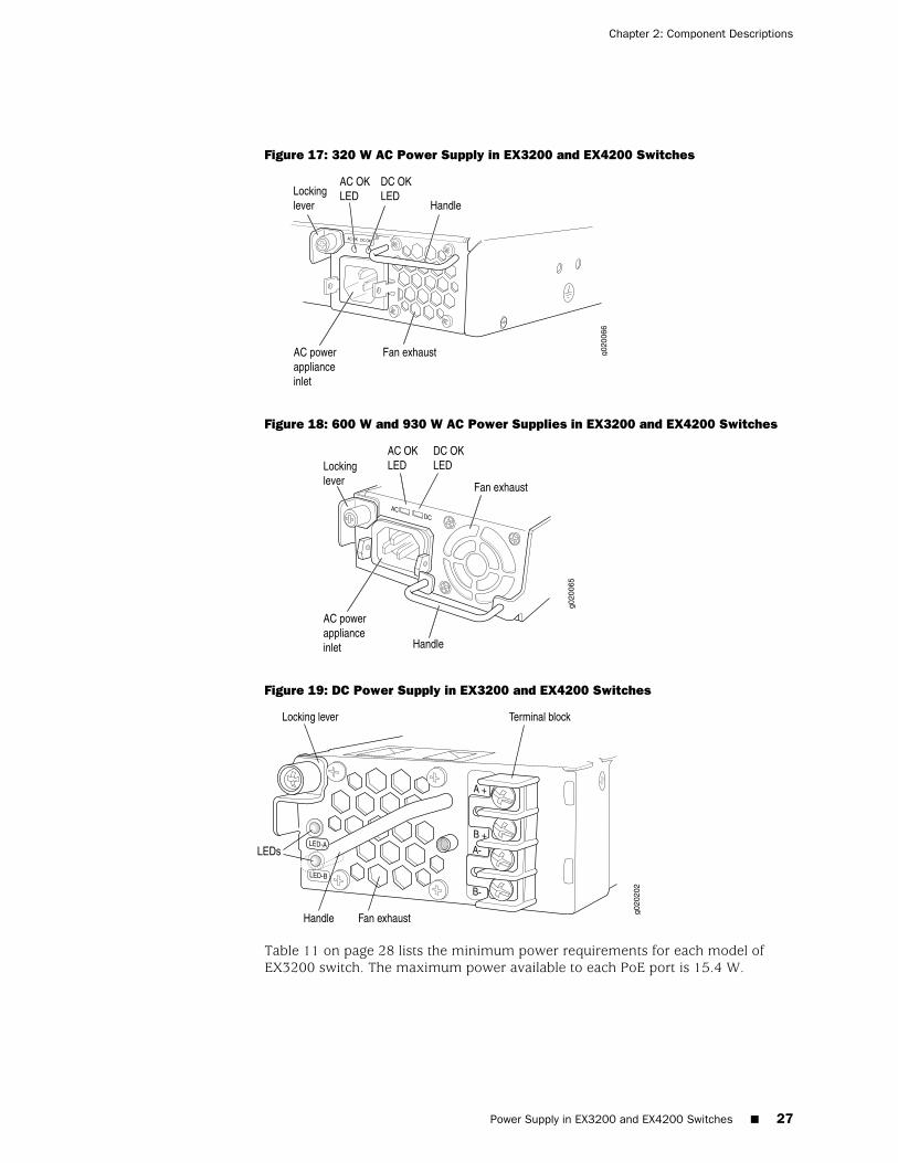
Figure 17: 320 W AC Power Supply in EX3200 and EX4200 Switches
Figure 18: 600 W and 930 W AC Power Supplies in EX3200 and EX4200 Switches
Figure 19: DC Power Supply in EX3200 and EX4200 Switches
Table 11 on page 28 lists the minimum power requirements for each model ofEX3200 switch. The maximum power available to each PoE port is 15.4 W.
Power Supply in EX3200 and EX4200 Switches ■ 27
Chapter 2: Component Descriptions
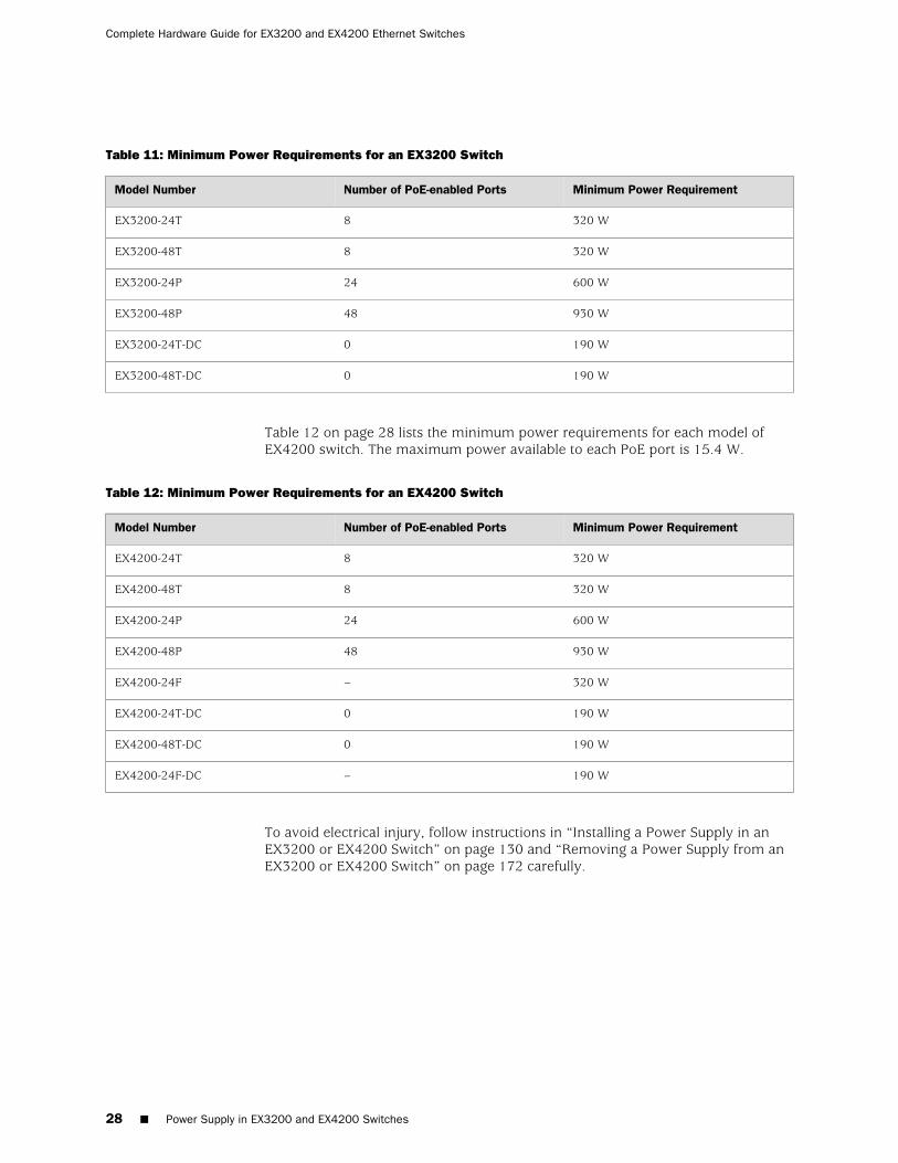
Table 11: Minimum Power Requirements for an EX3200 Switch
Minimum Power RequirementNumber of PoE-enabled PortsModel Number
320 W8EX3200-24T
320 W8EX3200-48T
600 W24EX3200-24P
930 W48EX3200-48P
190 W0EX3200-24T-DC
190 W0EX3200-48T-DC
Table 12 on page 28 lists the minimum power requirements for each model ofEX4200 switch. The maximum power available to each PoE port is 15.4 W.
Table 12: Minimum Power Requirements for an EX4200 Switch
Minimum Power RequirementNumber of PoE-enabled PortsModel Number
320 W8EX4200-24T
320 W8EX4200-48T
600 W24EX4200-24P
930 W48EX4200-48P
320 W–EX4200-24F
190 W0EX4200-24T-DC
190 W0EX4200-48T-DC
190 W–EX4200-24F-DC
To avoid electrical injury, follow instructions in “Installing a Power Supply in anEX3200 or EX4200 Switch” on page 130 and “Removing a Power Supply from anEX3200 or EX4200 Switch” on page 172 carefully.
28 ■ Power Supply in EX3200 and EX4200 Switches
Complete Hardware Guide for EX3200 and EX4200 Ethernet Switches
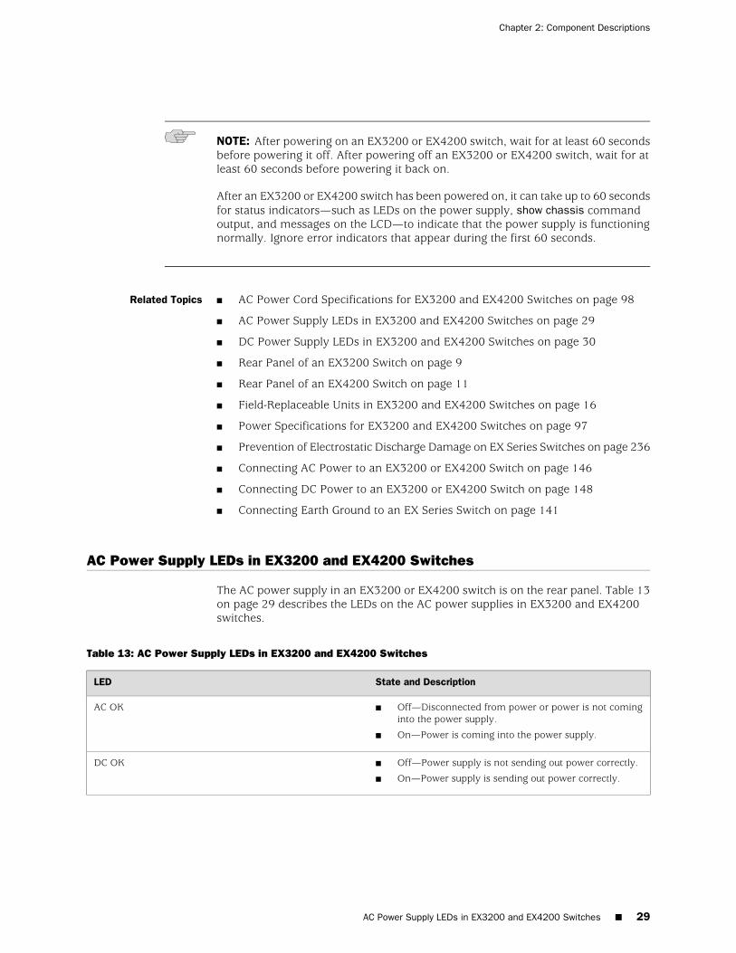
NOTE: After powering on an EX3200 or EX4200 switch, wait for at least 60 secondsbefore powering it off. After powering off an EX3200 or EX4200 switch, wait for atleast 60 seconds before powering it back on.
After an EX3200 or EX4200 switch has been powered on, it can take up to 60 secondsfor status indicators—such as LEDs on the power supply, show chassis commandoutput, and messages on the LCD—to indicate that the power supply is functioningnormally. Ignore error indicators that appear during the first 60 seconds.
Related Topics ■ AC Power Cord Specifications for EX3200 and EX4200 Switches on page 98
■ AC Power Supply LEDs in EX3200 and EX4200 Switches on page 29
■ DC Power Supply LEDs in EX3200 and EX4200 Switches on page 30
■ Rear Panel of an EX3200 Switch on page 9
■ Rear Panel of an EX4200 Switch on page 11
■ Field-Replaceable Units in EX3200 and EX4200 Switches on page 16
■ Power Specifications for EX3200 and EX4200 Switches on page 97
■ Prevention of Electrostatic Discharge Damage on EX Series Switches on page 236
■ Connecting AC Power to an EX3200 or EX4200 Switch on page 146
■ Connecting DC Power to an EX3200 or EX4200 Switch on page 148
■ Connecting Earth Ground to an EX Series Switch on page 141
AC Power Supply LEDs in EX3200 and EX4200 Switches
The AC power supply in an EX3200 or EX4200 switch is on the rear panel. Table 13on page 29 describes the LEDs on the AC power supplies in EX3200 and EX4200switches.
Table 13: AC Power Supply LEDs in EX3200 and EX4200 Switches
State and DescriptionLED
■ Off—Disconnected from power or power is not cominginto the power supply.
■ On—Power is coming into the power supply.
AC OK
■ Off—Power supply is not sending out power correctly.
■ On—Power supply is sending out power correctly.
DC OK
AC Power Supply LEDs in EX3200 and EX4200 Switches ■ 29
Chapter 2: Component Descriptions
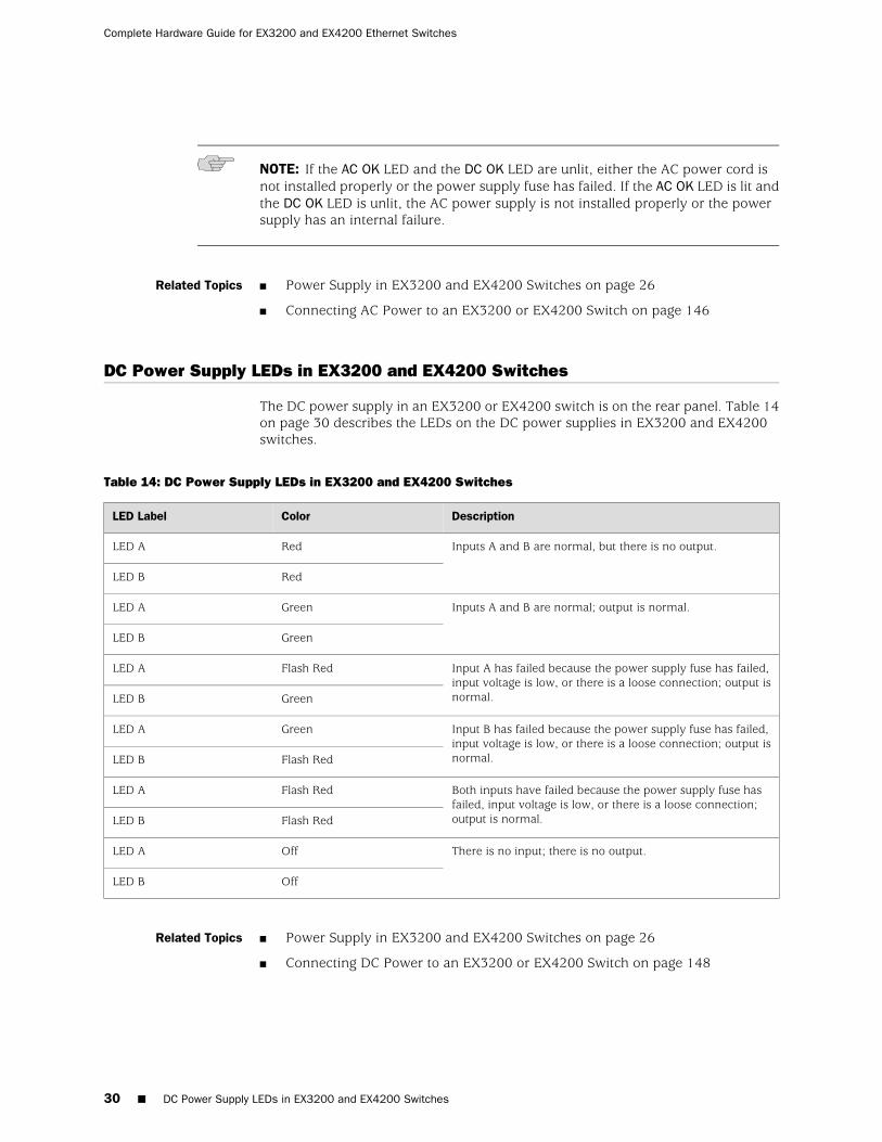
NOTE: If the AC OK LED and the DC OK LED are unlit, either the AC power cord isnot installed properly or the power supply fuse has failed. If the AC OK LED is lit andthe DC OK LED is unlit, the AC power supply is not installed properly or the powersupply has an internal failure.
Related Topics Power Supply in EX3200 and EX4200 Switches on page 26■
■ Connecting AC Power to an EX3200 or EX4200 Switch on page 146
DC Power Supply LEDs in EX3200 and EX4200 Switches
The DC power supply in an EX3200 or EX4200 switch is on the rear panel. Table 14on page 30 describes the LEDs on the DC power supplies in EX3200 and EX4200switches.
Table 14: DC Power Supply LEDs in EX3200 and EX4200 Switches
DescriptionColorLED Label
Inputs A and B are normal, but there is no output.RedLED A
RedLED B
Inputs A and B are normal; output is normal.GreenLED A
GreenLED B
Input A has failed because the power supply fuse has failed,input voltage is low, or there is a loose connection; output isnormal.
Flash RedLED A
GreenLED B
Input B has failed because the power supply fuse has failed,input voltage is low, or there is a loose connection; output isnormal.
GreenLED A
Flash RedLED B
Both inputs have failed because the power supply fuse hasfailed, input voltage is low, or there is a loose connection;output is normal.
Flash RedLED A
Flash RedLED B
There is no input; there is no output.OffLED A
OffLED B
Related Topics Power Supply in EX3200 and EX4200 Switches on page 26■
■ Connecting DC Power to an EX3200 or EX4200 Switch on page 148
30 ■ DC Power Supply LEDs in EX3200 and EX4200 Switches
Complete Hardware Guide for EX3200 and EX4200 Ethernet Switches
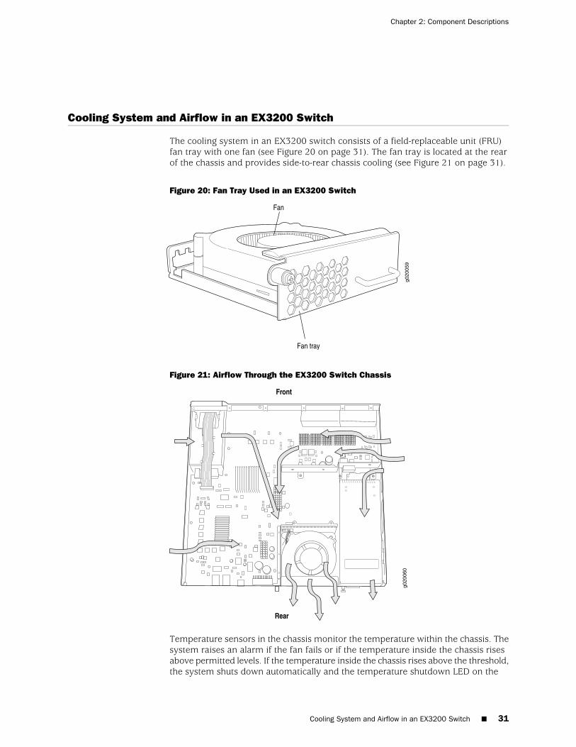
Cooling System and Airflow in an EX3200 Switch
The cooling system in an EX3200 switch consists of a field-replaceable unit (FRU)fan tray with one fan (see Figure 20 on page 31). The fan tray is located at the rearof the chassis and provides side-to-rear chassis cooling (see Figure 21 on page 31).
Figure 20: Fan Tray Used in an EX3200 Switch
Figure 21: Airflow Through the EX3200 Switch Chassis
Temperature sensors in the chassis monitor the temperature within the chassis. Thesystem raises an alarm if the fan fails or if the temperature inside the chassis risesabove permitted levels. If the temperature inside the chassis rises above the threshold,the system shuts down automatically and the temperature shutdown LED on the
Cooling System and Airflow in an EX3200 Switch ■ 31
Chapter 2: Component Descriptions
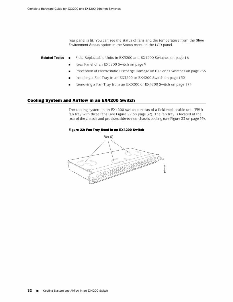
rear panel is lit. You can see the status of fans and the temperature from the ShowEnvironment Status option in the Status menu in the LCD panel.
Related Topics ■ Field-Replaceable Units in EX3200 and EX4200 Switches on page 16
■ Rear Panel of an EX3200 Switch on page 9
■ Prevention of Electrostatic Discharge Damage on EX Series Switches on page 236
■ Installing a Fan Tray in an EX3200 or EX4200 Switch on page 132
■ Removing a Fan Tray from an EX3200 or EX4200 Switch on page 174
Cooling System and Airflow in an EX4200 Switch
The cooling system in an EX4200 switch consists of a field-replaceable unit (FRU)fan tray with three fans (see Figure 22 on page 32). The fan tray is located at therear of the chassis and provides side-to-rear chassis cooling (see Figure 23 on page 33).
Figure 22: Fan Tray Used in an EX4200 Switch
32 ■ Cooling System and Airflow in an EX4200 Switch
Complete Hardware Guide for EX3200 and EX4200 Ethernet Switches
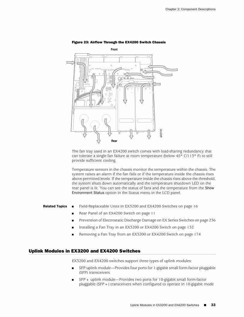
Figure 23: Airflow Through the EX4200 Switch Chassis
The fan tray used in an EX4200 switch comes with load-sharing redundancy thatcan tolerate a single fan failure at room temperature (below 45° C/113° F) to stillprovide sufficient cooling.
Temperature sensors in the chassis monitor the temperature within the chassis. Thesystem raises an alarm if the fan fails or if the temperature inside the chassis risesabove permitted levels. If the temperature inside the chassis rises above the threshold,the system shuts down automatically and the temperature shutdown LED on therear panel is lit. You can see the status of fans and the temperature from the ShowEnvironment Status option in the Status menu in the LCD panel.
Related Topics ■ Field-Replaceable Units in EX3200 and EX4200 Switches on page 16
■ Rear Panel of an EX4200 Switch on page 11
■ Prevention of Electrostatic Discharge Damage on EX Series Switches on page 236
■ Installing a Fan Tray in an EX3200 or EX4200 Switch on page 132
■ Removing a Fan Tray from an EX3200 or EX4200 Switch on page 174
Uplink Modules in EX3200 and EX4200 Switches
EX3200 and EX4200 switches support three types of uplink modules:
■ SFP uplink module—Provides four ports for 1-gigabit small form-factor pluggable(SFP) transceivers.
■ SFP+ uplink module—Provides two ports for 10-gigabit small form-factorpluggable (SFP+) transceivers when configured to operate in 10-gigabit mode
Uplink Modules in EX3200 and EX4200 Switches ■ 33
Chapter 2: Component Descriptions
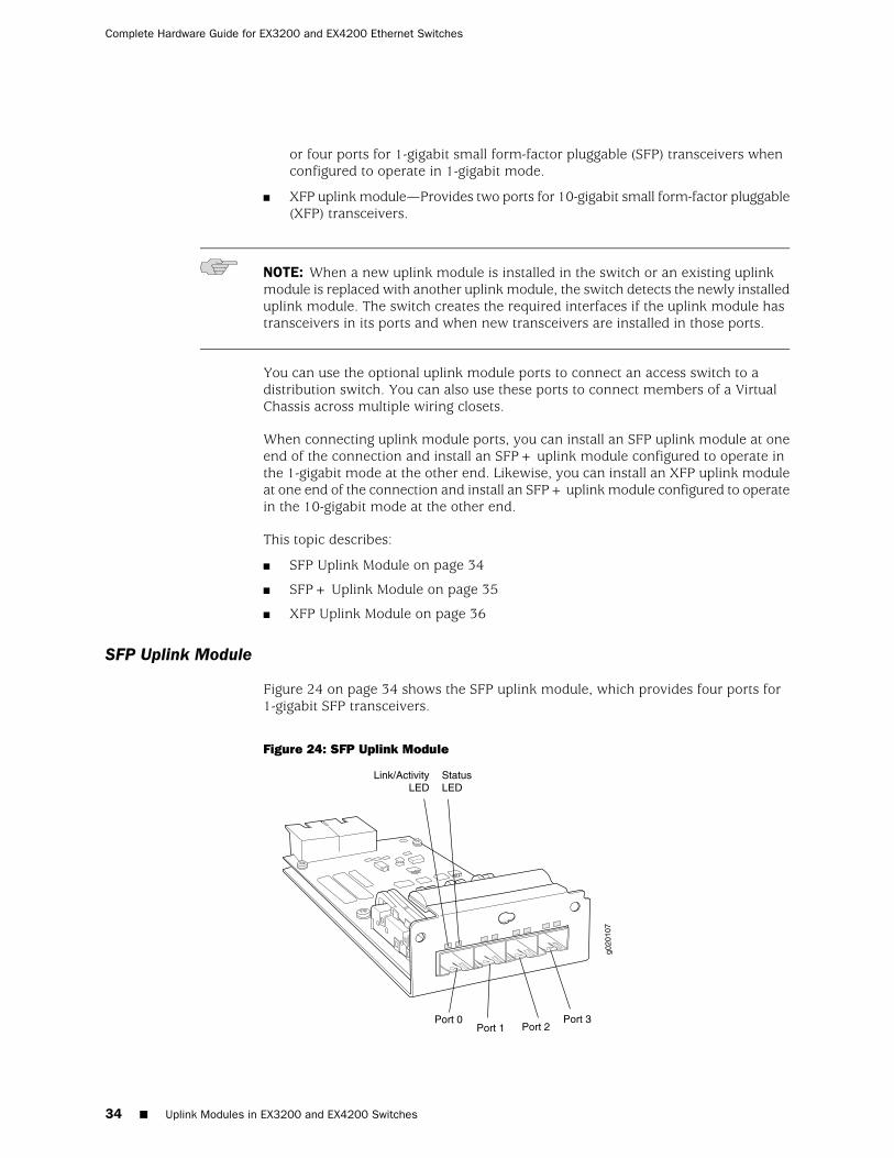
or four ports for 1-gigabit small form-factor pluggable (SFP) transceivers whenconfigured to operate in 1-gigabit mode.
■ XFP uplink module—Provides two ports for 10-gigabit small form-factor pluggable(XFP) transceivers.
NOTE: When a new uplink module is installed in the switch or an existing uplinkmodule is replaced with another uplink module, the switch detects the newly installeduplink module. The switch creates the required interfaces if the uplink module hastransceivers in its ports and when new transceivers are installed in those ports.
You can use the optional uplink module ports to connect an access switch to adistribution switch. You can also use these ports to connect members of a VirtualChassis across multiple wiring closets.
When connecting uplink module ports, you can install an SFP uplink module at oneend of the connection and install an SFP+ uplink module configured to operate inthe 1-gigabit mode at the other end. Likewise, you can install an XFP uplink moduleat one end of the connection and install an SFP+ uplink module configured to operatein the 10-gigabit mode at the other end.
This topic describes:
■ SFP Uplink Module on page 34
■ SFP+ Uplink Module on page 35
■ XFP Uplink Module on page 36
SFP Uplink Module
Figure 24 on page 34 shows the SFP uplink module, which provides four ports for1-gigabit SFP transceivers.
Figure 24: SFP Uplink Module
34 ■ Uplink Modules in EX3200 and EX4200 Switches
Complete Hardware Guide for EX3200 and EX4200 Ethernet Switches
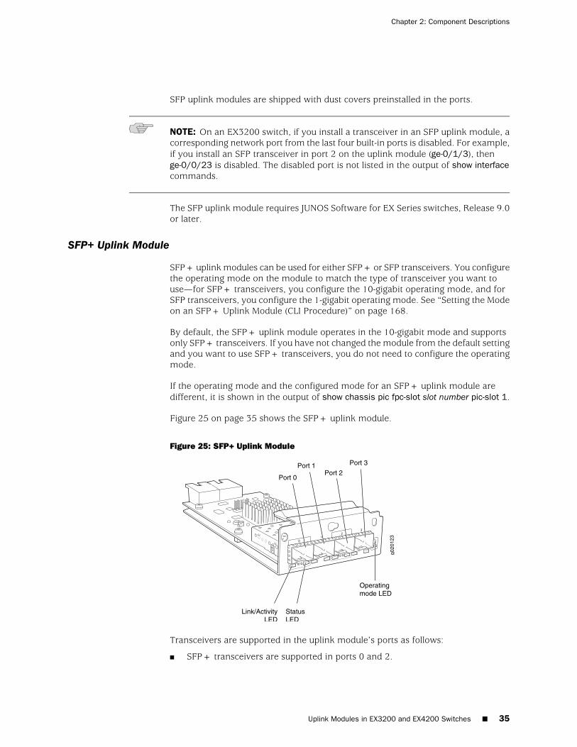
SFP uplink modules are shipped with dust covers preinstalled in the ports.
NOTE: On an EX3200 switch, if you install a transceiver in an SFP uplink module, acorresponding network port from the last four built-in ports is disabled. For example,if you install an SFP transceiver in port 2 on the uplink module (ge-0/1/3), thenge-0/0/23 is disabled. The disabled port is not listed in the output of show interfacecommands.
The SFP uplink module requires JUNOS Software for EX Series switches, Release 9.0or later.
SFP+ Uplink Module
SFP+ uplink modules can be used for either SFP+ or SFP transceivers. You configurethe operating mode on the module to match the type of transceiver you want touse—for SFP+ transceivers, you configure the 10-gigabit operating mode, and forSFP transceivers, you configure the 1-gigabit operating mode. See “Setting the Modeon an SFP+ Uplink Module (CLI Procedure)” on page 168.
By default, the SFP+ uplink module operates in the 10-gigabit mode and supportsonly SFP+ transceivers. If you have not changed the module from the default settingand you want to use SFP+ transceivers, you do not need to configure the operatingmode.
If the operating mode and the configured mode for an SFP+ uplink module aredifferent, it is shown in the output of show chassis pic fpc-slot slot number pic-slot 1.
Figure 25 on page 35 shows the SFP+ uplink module.
Figure 25: SFP+ Uplink Module
Transceivers are supported in the uplink module’s ports as follows:
■ SFP+ transceivers are supported in ports 0 and 2.
Uplink Modules in EX3200 and EX4200 Switches ■ 35
Chapter 2: Component Descriptions
■ SFP transceivers are supported in all four ports.
The ports that support SFP+ transceivers are labeled 10 G on the uplink module’sfaceplate (see Figure 25 on page 35).
NOTE: When an SFP+ uplink module is operating in 10-gigabit mode:
■ Only the 10-gigabit ports (ports 0 and 2) are enabled.
■ You can use only SFP+ transceivers in those ports.
When an SFP+ uplink module is operating in 1-gigabit mode:
■ All four ports are enabled.
■ You can use only SFP transceivers in all four ports.
The SFP+ uplink module has an LED on the faceplate (labeled Operating mode LEDin Figure 25 on page 35) that indicates the operating mode. If the uplink module isoperating in the 10-gigabit mode, the LED is lit. If the uplink module is operating inthe 1-gigabit mode, the LED is unlit.
SFP+ uplink modules are shipped with dust covers preinstalled in the ports.
NOTE: On an EX3200 switch, if you install a transceiver in an SFP+ uplink modulewhen the uplink module is operating in the 1-gigabit mode, a corresponding networkport from the last four built-in ports is disabled. For example, if you install an SFP+transceiver in port 2 on the uplink module (ge-0/1/3), then ge-0/0/23 is disabled.The disabled port is not listed in the output of show interface commands.
The SFP+ uplink module requires JUNOS Software for EX Series switches, Release9.4 or later.
XFP Uplink Module
Figure 26 on page 37 shows the XFP uplink module, which provides two ports for10-gigabit XFP transceivers.
36 ■ Uplink Modules in EX3200 and EX4200 Switches
Complete Hardware Guide for EX3200 and EX4200 Ethernet Switches
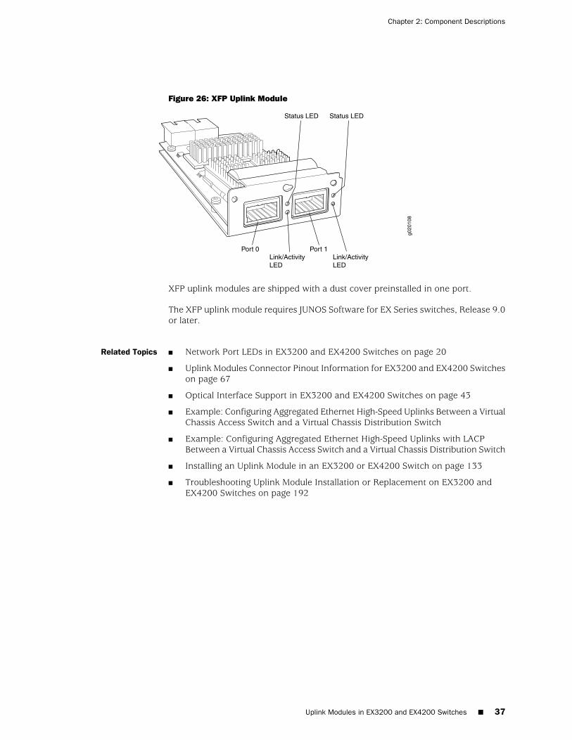
Figure 26: XFP Uplink Module
g020
108
Link/ActivityLED
Link/ActivityLED
Status LED Status LED
Port 0 Port 1
XFP uplink modules are shipped with a dust cover preinstalled in one port.
The XFP uplink module requires JUNOS Software for EX Series switches, Release 9.0or later.
Related Topics ■ Network Port LEDs in EX3200 and EX4200 Switches on page 20
■ Uplink Modules Connector Pinout Information for EX3200 and EX4200 Switcheson page 67
■ Optical Interface Support in EX3200 and EX4200 Switches on page 43
■ Example: Configuring Aggregated Ethernet High-Speed Uplinks Between a VirtualChassis Access Switch and a Virtual Chassis Distribution Switch
■ Example: Configuring Aggregated Ethernet High-Speed Uplinks with LACPBetween a Virtual Chassis Access Switch and a Virtual Chassis Distribution Switch
■ Installing an Uplink Module in an EX3200 or EX4200 Switch on page 133
■ Troubleshooting Uplink Module Installation or Replacement on EX3200 andEX4200 Switches on page 192
Uplink Modules in EX3200 and EX4200 Switches ■ 37
Chapter 2: Component Descriptions

38 ■ Uplink Modules in EX3200 and EX4200 Switches
Complete Hardware Guide for EX3200 and EX4200 Ethernet Switches
Chapter 3
Component Specifications
■ USB Port Specifications for an EX Series Switch on page 39
■ Network Port Connector Pinout Information for an EX3200 or EX4200Switch on page 40
■ Console Port Connector Pinout Information for an EX Series Switch on page 41
■ Management Port Connector Pinout Information for an EX3200 or EX4200Switch on page 42
■ Optical Interface Support in EX3200 and EX4200 Switches on page 43
■ Uplink Modules Connector Pinout Information for EX3200 and EX4200Switches on page 67
■ Virtual Chassis Ports Connector Pinout Information for EX4200Switches on page 74
USB Port Specifications for an EX Series Switch
The following Juniper Networks USB flash drives have been tested and are officiallysupported for the USB port on all EX Series switches:
■ RE-USB-1G-S
■ RE-USB-2G-S
■ RE-USB-4G-S
CAUTION: Any USB memory product not listed as supported for EX Series switcheshas not been tested by Juniper Networks. The use of any unsupported USB memoryproduct could expose your EX Series switch to unpredictable behavior. JuniperNetworks Technical Assistance Center (JTAC) can provide only limited support forissues related to unsupported hardware. We strongly recommend that you use onlysupported USB flash drives.
All USB flash drives used on EX Series switches must have the following features:
■ USB 2.0 or later.
■ Formatted with a FAT or MS-DOS file system.
■ If the switch is running JUNOS Release 9.5 or earlier, the formatting methodmust use a master boot record. Windows formatting, by default, does not use a
USB Port Specifications for an EX Series Switch ■ 39
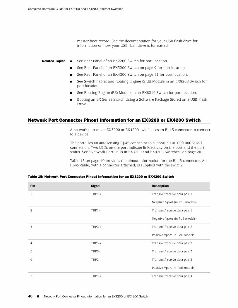
master boot record. See the documentation for your USB flash drive forinformation on how your USB flash drive is formatted.
Related Topics ■ See Rear Panel of an EX2200 Switch for port location.
■ See Rear Panel of an EX3200 Switch on page 9 for port location.
■ See Rear Panel of an EX4200 Switch on page 11 for port location.
■ See Switch Fabric and Routing Engine (SRE) Module in an EX8208 Switch forport location.
■ See Routing Engine (RE) Module in an EX8216 Switch for port location.
■ Booting an EX Series Switch Using a Software Package Stored on a USB FlashDrive
Network Port Connector Pinout Information for an EX3200 or EX4200 Switch
A network port on an EX3200 or EX4200 switch uses an RJ-45 connector to connectto a device.
The port uses an autosensing RJ-45 connector to support a 10/100/1000Base-Tconnection. Two LEDs on the port indicate link/activity on the port and the portstatus. See “Network Port LEDs in EX3200 and EX4200 Switches” on page 20.
Table 15 on page 40 provides the pinout information for the RJ-45 connector. AnRJ-45 cable, with a connector attached, is supplied with the switch.
Table 15: Network Port Connector Pinout Information for an EX3200 or EX4200 Switch
DescriptionSignalPin
Transmit/receive data pair 1
Negative Vport (in PoE models)
TRP1+1
Transmit/receive data pair 1
Negative Vport (in PoE models)
TRP1-2
Transmit/receive data pair 2
Positive Vport (in PoE models)
TRP2+3
Transmit/receive data pair 3TRP3+4
Transmit/receive data pair 3TRP3-5
Transmit/receive data pair 2
Positive Vport (in PoE models)
TRP2-6
Transmit/receive data pair 4TRP4+7
40 ■ Network Port Connector Pinout Information for an EX3200 or EX4200 Switch
Complete Hardware Guide for EX3200 and EX4200 Ethernet Switches
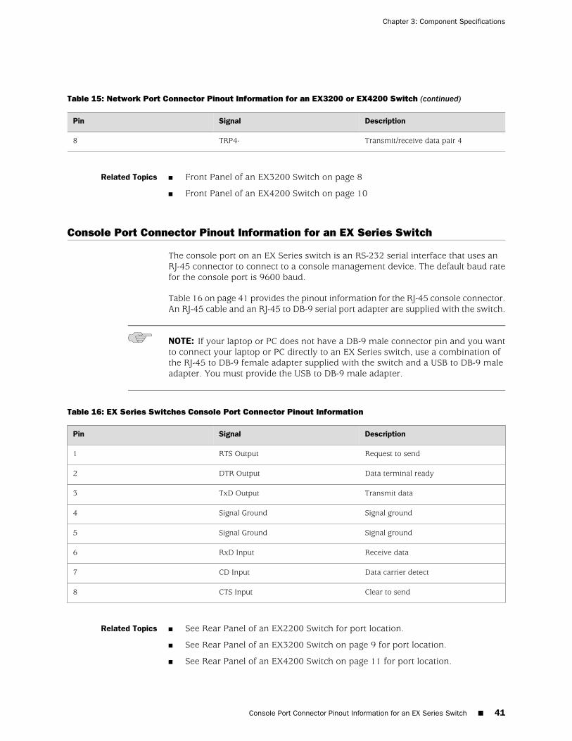
Table 15: Network Port Connector Pinout Information for an EX3200 or EX4200 Switch (continued)
DescriptionSignalPin
Transmit/receive data pair 4TRP4-8
Related Topics Front Panel of an EX3200 Switch on page 8■
■ Front Panel of an EX4200 Switch on page 10
Console Port Connector Pinout Information for an EX Series Switch
The console port on an EX Series switch is an RS-232 serial interface that uses anRJ-45 connector to connect to a console management device. The default baud ratefor the console port is 9600 baud.
Table 16 on page 41 provides the pinout information for the RJ-45 console connector.An RJ-45 cable and an RJ-45 to DB-9 serial port adapter are supplied with the switch.
NOTE: If your laptop or PC does not have a DB-9 male connector pin and you wantto connect your laptop or PC directly to an EX Series switch, use a combination ofthe RJ-45 to DB-9 female adapter supplied with the switch and a USB to DB-9 maleadapter. You must provide the USB to DB-9 male adapter.
Table 16: EX Series Switches Console Port Connector Pinout Information
DescriptionSignalPin
Request to sendRTS Output1
Data terminal readyDTR Output2
Transmit dataTxD Output3
Signal groundSignal Ground4
Signal groundSignal Ground5
Receive dataRxD Input6
Data carrier detectCD Input7
Clear to sendCTS Input8
Related Topics ■ See Rear Panel of an EX2200 Switch for port location.
■ See Rear Panel of an EX3200 Switch on page 9 for port location.
■ See Rear Panel of an EX4200 Switch on page 11 for port location.
Console Port Connector Pinout Information for an EX Series Switch ■ 41
Chapter 3: Component Specifications

■ See Switch Fabric and Routing Engine (SRE) Module in an EX8208 Switch forport location.
■ See Routing Engine (RE) Module in an EX8216 Switch for port location.
■ Connecting an EX Series Switch to a Management Console on page 153
Management Port Connector Pinout Information for an EX3200 or EX4200 Switch
The management port on an EX3200 or EX4200 switch uses an RJ-45 connector toconnect to a management device for out-of-band management.
The port uses an autosensing RJ-45 connector to support a 10/100/1000Base-Tconnection. Two LEDs on the port indicate link/activity on the port and theadministrative status of the port. See “Management Port LEDs in EX3200 and EX4200Switches” on page 24.
Table 17 on page 42 provides the pinout information of the RJ-45 connector. AnRJ-45 cable, with a connector attached, is supplied with the switch.
Table 17: Management Port Connector Pinout Information for an EX3200 or EX4200 Switch
DescriptionSignalPin
Transmit/receive data pair 1TRP1+1
Transmit/receive data pair 1TRP1-2
Transmit/receive data pair 2TRP2+3
Transmit/receive data pair 3TRP3+4
Transmit/receive data pair 3TRP3-5
Transmit/receive data pair 2TRP2-6
Transmit/receive data pair 4TRP4+7
Transmit/receive data pair 4TRP4-8
Related Topics See Rear Panel of an EX3200 Switch on page 9 for port location.■
■ See Rear Panel of an EX4200 Switch on page 11 for port location.
■ Connecting an EX Series Switch to a Network for Out-of-Band Management onpage 152
42 ■ Management Port Connector Pinout Information for an EX3200 or EX4200 Switch
Complete Hardware Guide for EX3200 and EX4200 Ethernet Switches

Optical Interface Support in EX3200 and EX4200 Switches
Optional uplink modules for EX3200 and EX4200 switches support SFP, SFP+, orXFP transceivers. This topic describes the optical interfaces supported for thosetransceivers. It also lists the copper interface supported for the SFP transceivers.
NOTE: Use only optical transceivers and optical connectors purchased from JuniperNetworks for your EX Series switch.
The Gigabit Ethernet SFP, SFP+, or XFP transceivers installed in EX3200 or EX4200switches support digital optical monitoring (DOM): you can view the diagnostic detailsfor these transceivers by issuing the operational mode CLI command show interfacesdiagnostics optics. The command does not give any output for copper transceivers,Fast Ethernet transceivers, or transceivers not purchased from Juniper Networks.
The four tables in this topic describe the optical interface support over single-modefiber-optic (SMF) and multimode fiber-optic (MMF) cables for SFP, SFP+, and XFPtransceivers and over the copper interface for SFP transceivers:
■ Table 18 on page 44—Optical interface support and copper interface supportfor Gigabit Ethernet SFP transceivers.
■ Table 19 on page 55—Optical interface support for Fast Ethernet SFP transceivers.
■ Table 20 on page 61—Optical interface support for Gigabit Ethernet SFP+transceivers.
■ Table 21 on page 64—Optical interface support for Gigabit Ethernet XFPtransceivers.
Optical Interface Support in EX3200 and EX4200 Switches ■ 43
Chapter 3: Component Specifications
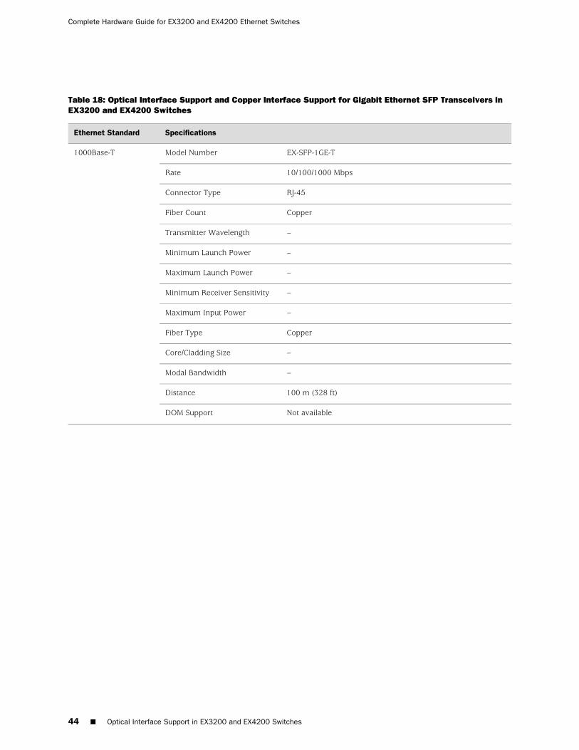
Table 18: Optical Interface Support and Copper Interface Support for Gigabit Ethernet SFP Transceivers inEX3200 and EX4200 Switches
SpecificationsEthernet Standard
EX-SFP-1GE-TModel Number1000Base-T
10/100/1000 MbpsRate
RJ-45Connector Type
CopperFiber Count
–Transmitter Wavelength
–Minimum Launch Power
–Maximum Launch Power
–Minimum Receiver Sensitivity
–Maximum Input Power
CopperFiber Type
–Core/Cladding Size
–Modal Bandwidth
100 m (328 ft)Distance
Not availableDOM Support
44 ■ Optical Interface Support in EX3200 and EX4200 Switches
Complete Hardware Guide for EX3200 and EX4200 Ethernet Switches
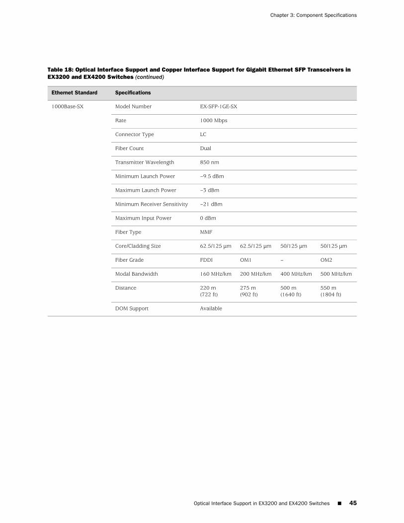
Table 18: Optical Interface Support and Copper Interface Support for Gigabit Ethernet SFP Transceivers inEX3200 and EX4200 Switches (continued)
SpecificationsEthernet Standard
EX-SFP-1GE-SXModel Number1000Base-SX
1000 MbpsRate
LCConnector Type
DualFiber Count
850 nmTransmitter Wavelength
–9.5 dBmMinimum Launch Power
–3 dBmMaximum Launch Power
–21 dBmMinimum Receiver Sensitivity
0 dBmMaximum Input Power
MMFFiber Type
50/125 µm50/125 µm62.5/125 µm62.5/125 µmCore/Cladding Size
OM2–OM1FDDIFiber Grade
500 MHz/km400 MHz/km200 MHz/km160 MHz/kmModal Bandwidth
550 m(1804 ft)
500 m(1640 ft)
275 m(902 ft)
220 m(722 ft)
Distance
AvailableDOM Support
Optical Interface Support in EX3200 and EX4200 Switches ■ 45
Chapter 3: Component Specifications
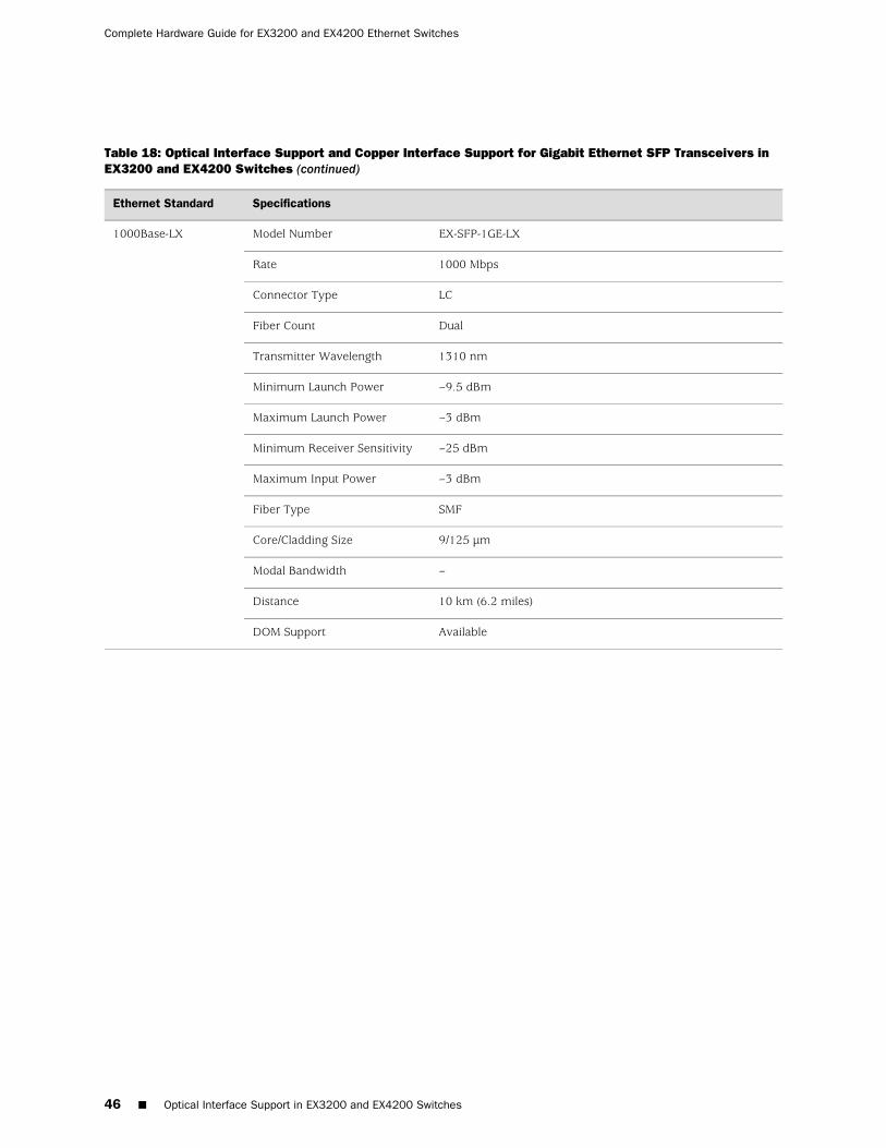
Table 18: Optical Interface Support and Copper Interface Support for Gigabit Ethernet SFP Transceivers inEX3200 and EX4200 Switches (continued)
SpecificationsEthernet Standard
EX-SFP-1GE-LXModel Number1000Base-LX
1000 MbpsRate
LCConnector Type
DualFiber Count
1310 nmTransmitter Wavelength
–9.5 dBmMinimum Launch Power
–3 dBmMaximum Launch Power
–25 dBmMinimum Receiver Sensitivity
–3 dBmMaximum Input Power
SMFFiber Type
9/125 µmCore/Cladding Size
–Modal Bandwidth
10 km (6.2 miles)Distance
AvailableDOM Support
46 ■ Optical Interface Support in EX3200 and EX4200 Switches
Complete Hardware Guide for EX3200 and EX4200 Ethernet Switches

Table 18: Optical Interface Support and Copper Interface Support for Gigabit Ethernet SFP Transceivers inEX3200 and EX4200 Switches (continued)
SpecificationsEthernet Standard
EX-SFP-GE10KT13R14Model Number1000Base-BX-U
1000 MbpsRate
LCConnector Type
SingleFiber Count
1310 nmTransmitter Wavelength
1490 nmReceiver Wavelength
–9 dBmMinimum Launch Power
–3 dBmMaximum Launch Power
–30 dBmMinimum Receiver Sensitivity
–3 dBmMaximum Input Power
SMFFiber Type
9/125 µmCore/Cladding Size
–Modal Bandwidth
10 km (6.2 miles)Distance
AvailableDOM Support
Optical Interface Support in EX3200 and EX4200 Switches ■ 47
Chapter 3: Component Specifications
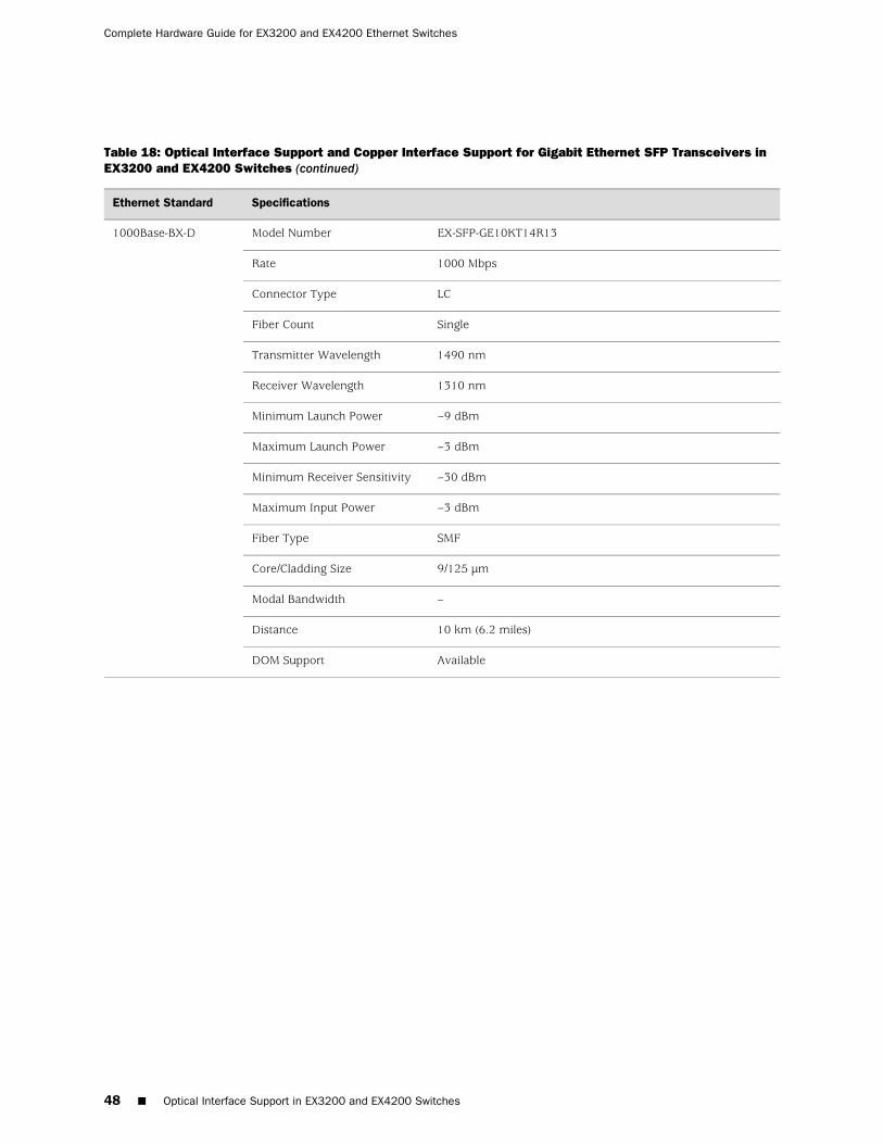
Table 18: Optical Interface Support and Copper Interface Support for Gigabit Ethernet SFP Transceivers inEX3200 and EX4200 Switches (continued)
SpecificationsEthernet Standard
EX-SFP-GE10KT14R13Model Number1000Base-BX-D
1000 MbpsRate
LCConnector Type
SingleFiber Count
1490 nmTransmitter Wavelength
1310 nmReceiver Wavelength
–9 dBmMinimum Launch Power
–3 dBmMaximum Launch Power
–30 dBmMinimum Receiver Sensitivity
–3 dBmMaximum Input Power
SMFFiber Type
9/125 µmCore/Cladding Size
–Modal Bandwidth
10 km (6.2 miles)Distance
AvailableDOM Support
48 ■ Optical Interface Support in EX3200 and EX4200 Switches
Complete Hardware Guide for EX3200 and EX4200 Ethernet Switches

Table 18: Optical Interface Support and Copper Interface Support for Gigabit Ethernet SFP Transceivers inEX3200 and EX4200 Switches (continued)
SpecificationsEthernet Standard
EX-SFP-GE10KT13R15Model Number1000Base-BX-U
1000 MbpsRate
LCConnector Type
SingleFiber Count
1310 nmTransmitter Wavelength
1550 nmReceiver Wavelength
–9 dBmMinimum Launch Power
–3 dBmMaximum Launch Power
–3 dBmMinimum Receiver Sensitivity
–21 dBmMaximum Input Power
SMFFiber Type
9/125 µmCore/Cladding Size
–Modal Bandwidth
10 km (6.2 miles)Distance
AvailableDOM Support
Optical Interface Support in EX3200 and EX4200 Switches ■ 49
Chapter 3: Component Specifications

Table 18: Optical Interface Support and Copper Interface Support for Gigabit Ethernet SFP Transceivers inEX3200 and EX4200 Switches (continued)
SpecificationsEthernet Standard
EX-SFP-GE10KT15R13Model Number1000Base-BX-D
1000 MbpsRate
LCConnector Type
SingleFiber Count
1550 nmTransmitter Wavelength
1310 nmReceiver Wavelength
–9 dBmMinimum Launch Power
–3 dBmMaximum Launch Power
–3 dBmMinimum Receiver Sensitivity
–21 dBmMaximum Input Power
SMFFiber Type
9/125 µmCore/Cladding Size
–Modal Bandwidth
10 km (6.2 miles)Distance
AvailableDOM Support
50 ■ Optical Interface Support in EX3200 and EX4200 Switches
Complete Hardware Guide for EX3200 and EX4200 Ethernet Switches
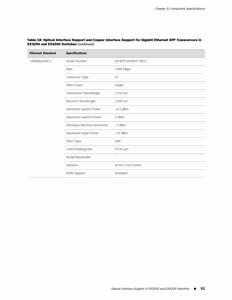
Table 18: Optical Interface Support and Copper Interface Support for Gigabit Ethernet SFP Transceivers inEX3200 and EX4200 Switches (continued)
SpecificationsEthernet Standard
EX-SFP-GE40KT13R15Model Number1000Base-BX-U
1000 MbpsRate
LCConnector Type
SingleFiber Count
1310 nmTransmitter Wavelength
1550 nmReceiver Wavelength
–6.5 dBmMinimum Launch Power
2 dBmMaximum Launch Power
–3 dBmMinimum Receiver Sensitivity
–23 dBmMaximum Input Power
SMFFiber Type
9/125 µmCore/Cladding Size
–Modal Bandwidth
40 km (24.8 miles)Distance
AvailableDOM Support
Optical Interface Support in EX3200 and EX4200 Switches ■ 51
Chapter 3: Component Specifications

Table 18: Optical Interface Support and Copper Interface Support for Gigabit Ethernet SFP Transceivers inEX3200 and EX4200 Switches (continued)
SpecificationsEthernet Standard
EX-SFP-GE40KT15R13Model Number1000Base-BX-D
1000 MbpsRate
LCConnector Type
SingleFiber Count
1550 nmTransmitter Wavelength
1310 nmReceiver Wavelength
–6.5 dBmMinimum Launch Power
2 dBmMaximum Launch Power
–3 dBmMinimum Receiver Sensitivity
–23 dBmMaximum Input Power
SMFFiber Type
9/125 µmCore/Cladding Size
–Modal Bandwidth
40 km (24.8 miles)Distance
AvailableDOM Support
52 ■ Optical Interface Support in EX3200 and EX4200 Switches
Complete Hardware Guide for EX3200 and EX4200 Ethernet Switches
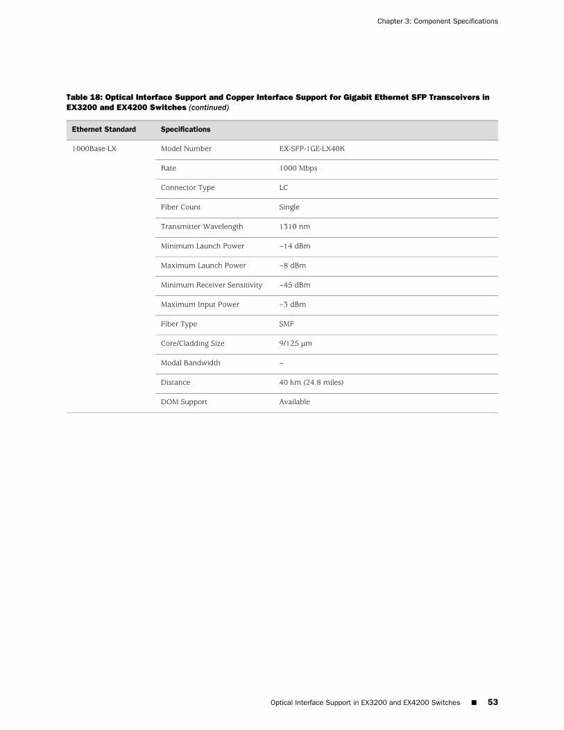
Table 18: Optical Interface Support and Copper Interface Support for Gigabit Ethernet SFP Transceivers inEX3200 and EX4200 Switches (continued)
SpecificationsEthernet Standard
EX-SFP-1GE-LX40KModel Number1000Base-LX
1000 MbpsRate
LCConnector Type
SingleFiber Count
1310 nmTransmitter Wavelength
–14 dBmMinimum Launch Power
–8 dBmMaximum Launch Power
–45 dBmMinimum Receiver Sensitivity
–3 dBmMaximum Input Power
SMFFiber Type
9/125 µmCore/Cladding Size
–Modal Bandwidth
40 km (24.8 miles)Distance
AvailableDOM Support
Optical Interface Support in EX3200 and EX4200 Switches ■ 53
Chapter 3: Component Specifications
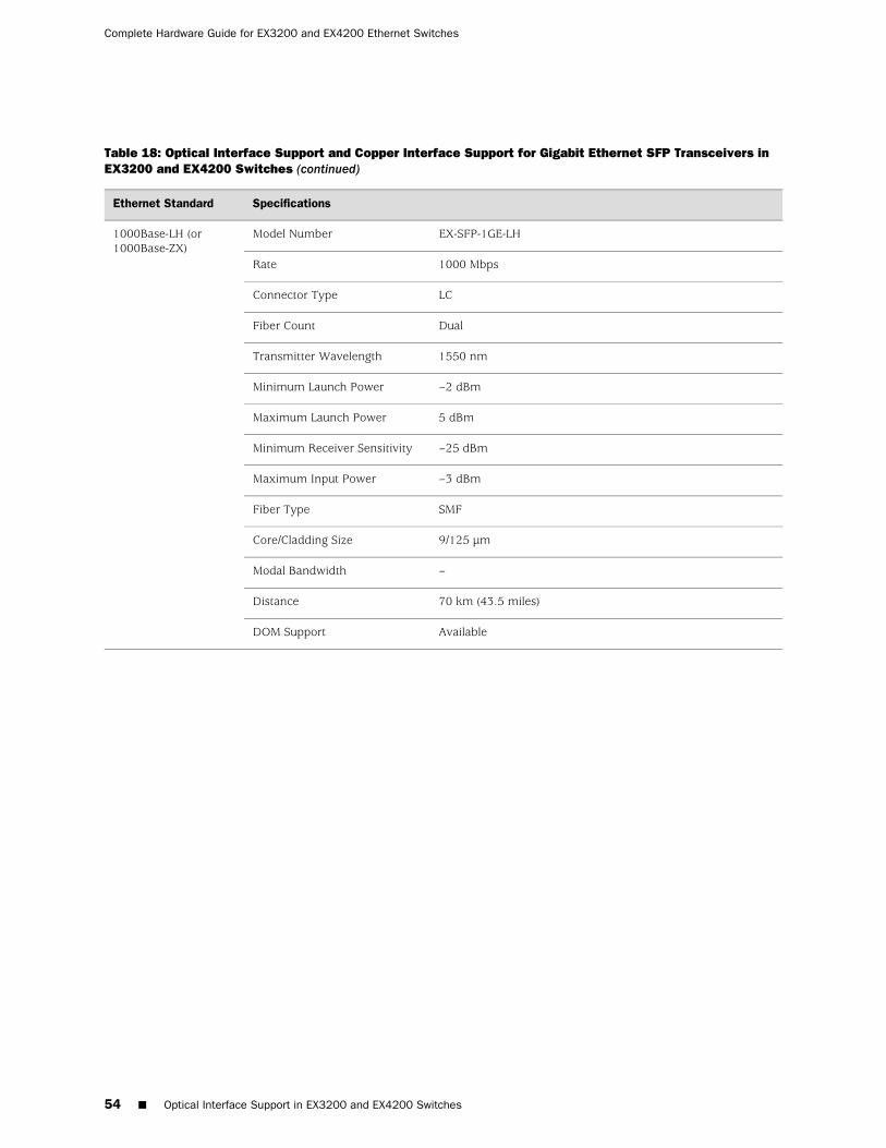
Table 18: Optical Interface Support and Copper Interface Support for Gigabit Ethernet SFP Transceivers inEX3200 and EX4200 Switches (continued)
SpecificationsEthernet Standard
EX-SFP-1GE-LHModel Number1000Base-LH (or1000Base-ZX)
1000 MbpsRate
LCConnector Type
DualFiber Count
1550 nmTransmitter Wavelength
–2 dBmMinimum Launch Power
5 dBmMaximum Launch Power
–25 dBmMinimum Receiver Sensitivity
–3 dBmMaximum Input Power
SMFFiber Type
9/125 µmCore/Cladding Size
–Modal Bandwidth
70 km (43.5 miles)Distance
AvailableDOM Support
54 ■ Optical Interface Support in EX3200 and EX4200 Switches
Complete Hardware Guide for EX3200 and EX4200 Ethernet Switches
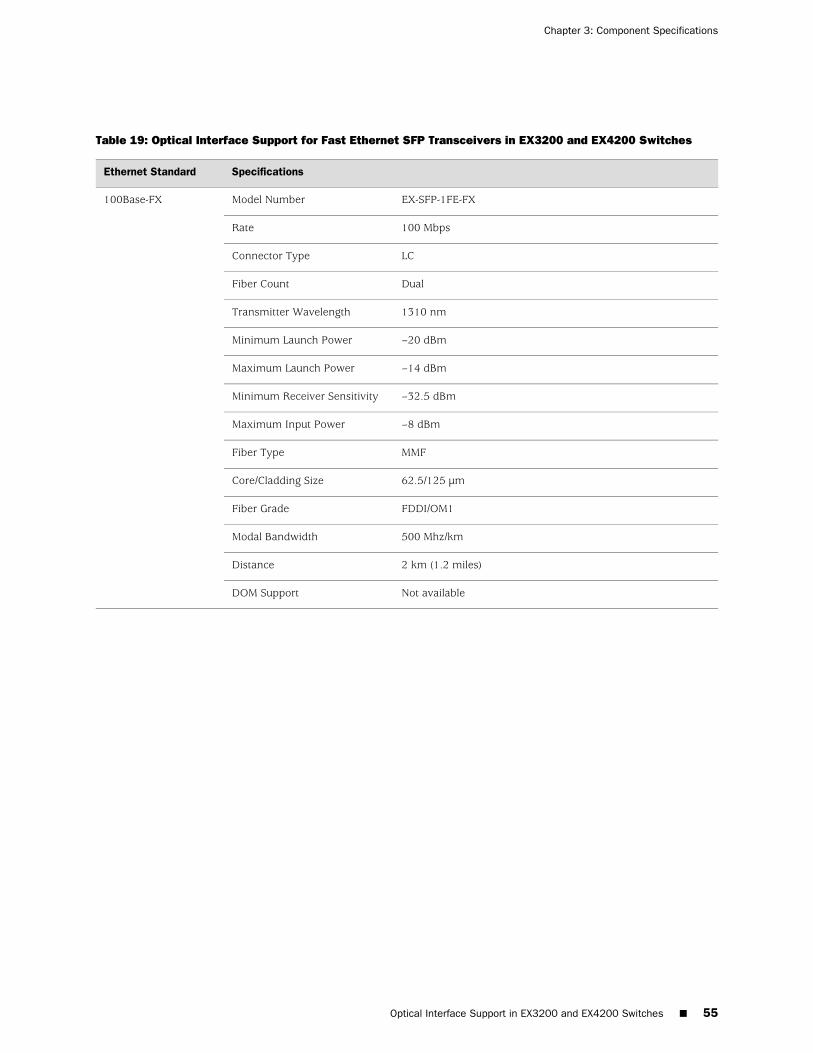
Table 19: Optical Interface Support for Fast Ethernet SFP Transceivers in EX3200 and EX4200 Switches
SpecificationsEthernet Standard
EX-SFP-1FE-FXModel Number100Base-FX
100 MbpsRate
LCConnector Type
DualFiber Count
1310 nmTransmitter Wavelength
–20 dBmMinimum Launch Power
–14 dBmMaximum Launch Power
–32.5 dBmMinimum Receiver Sensitivity
–8 dBmMaximum Input Power
MMFFiber Type
62.5/125 µmCore/Cladding Size
FDDI/OM1Fiber Grade
500 Mhz/kmModal Bandwidth
2 km (1.2 miles)Distance
Not availableDOM Support
Optical Interface Support in EX3200 and EX4200 Switches ■ 55
Chapter 3: Component Specifications
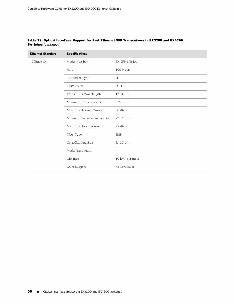
Table 19: Optical Interface Support for Fast Ethernet SFP Transceivers in EX3200 and EX4200Switches (continued)
SpecificationsEthernet Standard
EX-SFP-1FE-LXModel Number100Base-LX
100 MbpsRate
LCConnector Type
DualFiber Count
1310 nmTransmitter Wavelength
–15 dBmMinimum Launch Power
–8 dBmMaximum Launch Power
–31.5 dBmMinimum Receiver Sensitivity
–8 dBmMaximum Input Power
SMFFiber Type
9/125 µmCore/Cladding Size
–Modal Bandwidth
10 km (6.2 miles)Distance
Not availableDOM Support
56 ■ Optical Interface Support in EX3200 and EX4200 Switches
Complete Hardware Guide for EX3200 and EX4200 Ethernet Switches

Table 19: Optical Interface Support for Fast Ethernet SFP Transceivers in EX3200 and EX4200Switches (continued)
SpecificationsEthernet Standard
EX-SFP-FE20KT13R15Model Number100Base-BX-U
100 MbpsRate
LCConnector Type
SingleFiber Count
1310 nmTransmitter Wavelength
1550 nmReceiver Wavelength
–14 dBmMinimum Launch Power
–8 dBmMaximum Launch Power
–45 dBmMinimum Receiver Sensitivity
–8 dBmMaximum Input Power
SMFFiber Type
9/125 µmCore/Cladding Size
–Modal Bandwidth
20 km (12.4 miles)Distance
Not availableDOM Support
Optical Interface Support in EX3200 and EX4200 Switches ■ 57
Chapter 3: Component Specifications
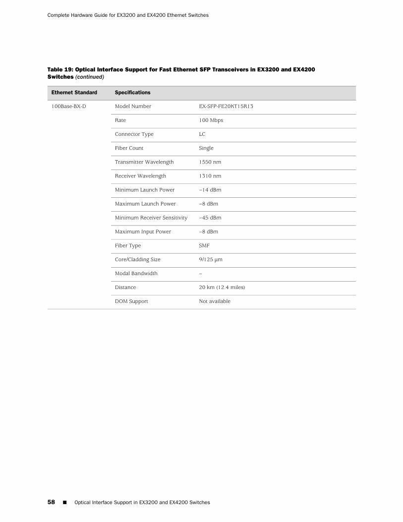
Table 19: Optical Interface Support for Fast Ethernet SFP Transceivers in EX3200 and EX4200Switches (continued)
SpecificationsEthernet Standard
EX-SFP-FE20KT15R13Model Number100Base-BX-D
100 MbpsRate
LCConnector Type
SingleFiber Count
1550 nmTransmitter Wavelength
1310 nmReceiver Wavelength
–14 dBmMinimum Launch Power
–8 dBmMaximum Launch Power
–45 dBmMinimum Receiver Sensitivity
–8 dBmMaximum Input Power
SMFFiber Type
9/125 µmCore/Cladding Size
–Modal Bandwidth
20 km (12.4 miles)Distance
Not availableDOM Support
58 ■ Optical Interface Support in EX3200 and EX4200 Switches
Complete Hardware Guide for EX3200 and EX4200 Ethernet Switches
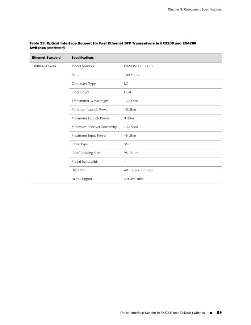
Table 19: Optical Interface Support for Fast Ethernet SFP Transceivers in EX3200 and EX4200Switches (continued)
SpecificationsEthernet Standard
EX-SFP-1FE-LX40KModel Number100Base-LX40K
100 MbpsRate
LCConnector Type
DualFiber Count
1310 nmTransmitter Wavelength
–5 dBmMinimum Launch Power
0 dBmMaximum Launch Power
–32 dBmMinimum Receiver Sensitivity
–8 dBmMaximum Input Power
SMFFiber Type
9/125 µmCore/Cladding Size
–Modal Bandwidth
40 km (24.8 miles)Distance
Not availableDOM Support
Optical Interface Support in EX3200 and EX4200 Switches ■ 59
Chapter 3: Component Specifications

Table 19: Optical Interface Support for Fast Ethernet SFP Transceivers in EX3200 and EX4200Switches (continued)
SpecificationsEthernet Standard
EX-SFP-1FE-LHModel Number100Base-LH (or100Base-ZX)
100 MbpsRate
LCConnector Type
DualFiber Count
1310 nmTransmitter Wavelength
–5 dBmMinimum Launch Power
0 dBmMaximum Launch Power
–32 dBmMinimum Receiver Sensitivity
–8 dBmMaximum Input Power
SMFFiber Type
9/125 µmCore/Cladding Size
–Modal Bandwidth
80 km (49.7 miles)Distance
Not availableDOM Support
60 ■ Optical Interface Support in EX3200 and EX4200 Switches
Complete Hardware Guide for EX3200 and EX4200 Ethernet Switches
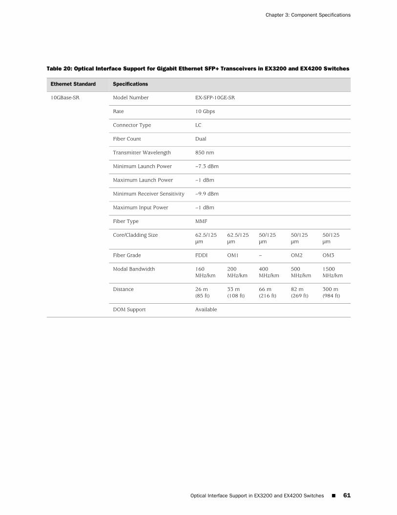
Table 20: Optical Interface Support for Gigabit Ethernet SFP+ Transceivers in EX3200 and EX4200 Switches
SpecificationsEthernet Standard
EX-SFP-10GE-SRModel Number10GBase-SR
10 GbpsRate
LCConnector Type
DualFiber Count
850 nmTransmitter Wavelength
–7.3 dBmMinimum Launch Power
–1 dBmMaximum Launch Power
–9.9 dBmMinimum Receiver Sensitivity
–1 dBmMaximum Input Power
MMFFiber Type
50/125µm
50/125µm
50/125µm
62.5/125µm
62.5/125µm
Core/Cladding Size
OM3OM2–OM1FDDIFiber Grade
1500MHz/km
500MHz/km
400MHz/km
200MHz/km
160MHz/km
Modal Bandwidth
300 m(984 ft)
82 m(269 ft)
66 m(216 ft)
33 m(108 ft)
26 m(85 ft)
Distance
AvailableDOM Support
Optical Interface Support in EX3200 and EX4200 Switches ■ 61
Chapter 3: Component Specifications
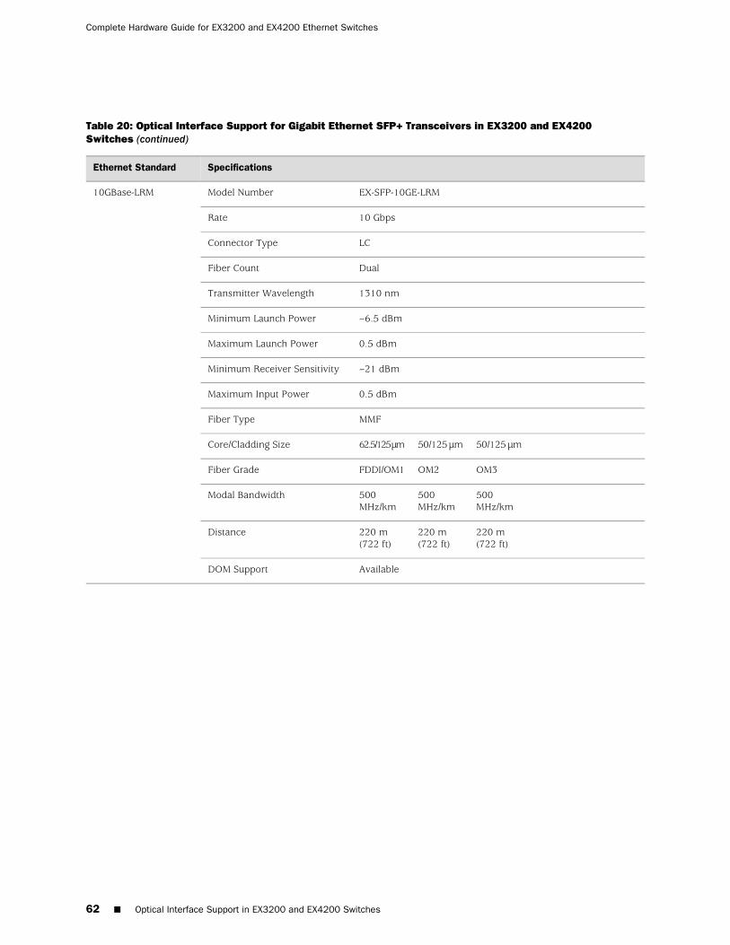
Table 20: Optical Interface Support for Gigabit Ethernet SFP+ Transceivers in EX3200 and EX4200Switches (continued)
SpecificationsEthernet Standard
EX-SFP-10GE-LRMModel Number10GBase-LRM
10 GbpsRate
LCConnector Type
DualFiber Count
1310 nmTransmitter Wavelength
–6.5 dBmMinimum Launch Power
0.5 dBmMaximum Launch Power
–21 dBmMinimum Receiver Sensitivity
0.5 dBmMaximum Input Power
MMFFiber Type
50/125 µm50/125 µm62.5/125 µmCore/Cladding Size
OM3OM2FDDI/OM1Fiber Grade
500MHz/km
500MHz/km
500MHz/km
Modal Bandwidth
220 m(722 ft)
220 m(722 ft)
220 m(722 ft)
Distance
AvailableDOM Support
62 ■ Optical Interface Support in EX3200 and EX4200 Switches
Complete Hardware Guide for EX3200 and EX4200 Ethernet Switches

Table 20: Optical Interface Support for Gigabit Ethernet SFP+ Transceivers in EX3200 and EX4200Switches (continued)
SpecificationsEthernet Standard
EX-SFP-10GE-LRModel Number10GBase-LR
10 GbpsRate
LCConnector Type
DualFiber Count
1310 nmTransmitter Wavelength
–8.2 dBmMinimum Launch Power
0.5 dBmMaximum Launch Power
–18 dBmMinimum Receiver Sensitivity
0.5 dBmMaximum Input Power
SMFFiber Type
9/125 µmCore/Cladding Size
–Modal Bandwidth
10 km (6.2 miles)Distance
AvailableDOM Support
Optical Interface Support in EX3200 and EX4200 Switches ■ 63
Chapter 3: Component Specifications
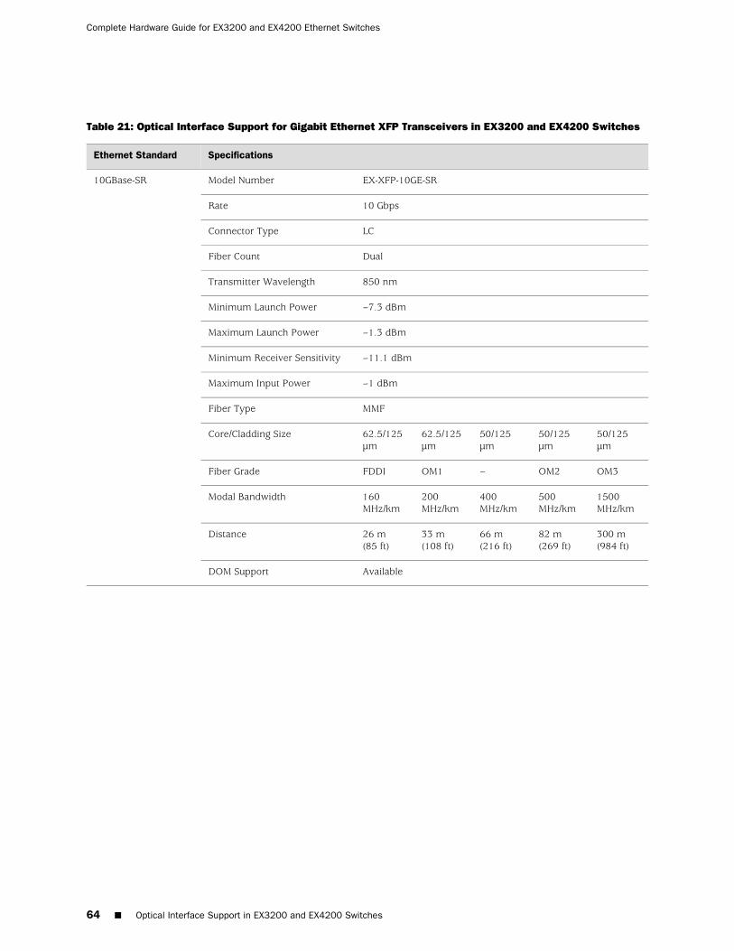
Table 21: Optical Interface Support for Gigabit Ethernet XFP Transceivers in EX3200 and EX4200 Switches
SpecificationsEthernet Standard
EX-XFP-10GE-SRModel Number10GBase-SR
10 GbpsRate
LCConnector Type
DualFiber Count
850 nmTransmitter Wavelength
–7.3 dBmMinimum Launch Power
–1.3 dBmMaximum Launch Power
–11.1 dBmMinimum Receiver Sensitivity
–1 dBmMaximum Input Power
MMFFiber Type
50/125µm
50/125µm
50/125µm
62.5/125µm
62.5/125µm
Core/Cladding Size
OM3OM2–OM1FDDIFiber Grade
1500MHz/km
500MHz/km
400MHz/km
200MHz/km
160MHz/km
Modal Bandwidth
300 m(984 ft)
82 m(269 ft)
66 m(216 ft)
33 m(108 ft)
26 m(85 ft)
Distance
AvailableDOM Support
64 ■ Optical Interface Support in EX3200 and EX4200 Switches
Complete Hardware Guide for EX3200 and EX4200 Ethernet Switches

Table 21: Optical Interface Support for Gigabit Ethernet XFP Transceivers in EX3200 and EX4200Switches (continued)
SpecificationsEthernet Standard
EX-XFP-10GE-LRModel Number10GBase-LR
10 GbpsRate
LCConnector Type
DualFiber Count
1310 nmTransmitter Wavelength
–8.2 dBmMinimum Launch Power
1 dBmMaximum Launch Power
–18 dBmMinimum Receiver Sensitivity
0.5 dBmMaximum Input Power
SMFFiber Type
9/125 µmCore/Cladding Size
–Modal Bandwidth
10 km (6.2 miles)Distance
AvailableDOM Support
Optical Interface Support in EX3200 and EX4200 Switches ■ 65
Chapter 3: Component Specifications
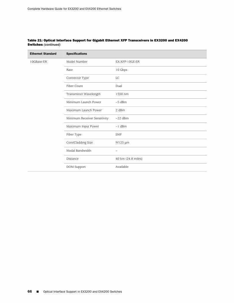
Table 21: Optical Interface Support for Gigabit Ethernet XFP Transceivers in EX3200 and EX4200Switches (continued)
SpecificationsEthernet Standard
EX-XFP-10GE-ERModel Number10GBase-ER
10 GbpsRate
LCConnector Type
DualFiber Count
1550 nmTransmitter Wavelength
–5 dBmMinimum Launch Power
2 dBmMaximum Launch Power
–22 dBmMinimum Receiver Sensitivity
–1 dBmMaximum Input Power
SMFFiber Type
9/125 µmCore/Cladding Size
–Modal Bandwidth
40 km (24.8 miles)Distance
AvailableDOM Support
66 ■ Optical Interface Support in EX3200 and EX4200 Switches
Complete Hardware Guide for EX3200 and EX4200 Ethernet Switches
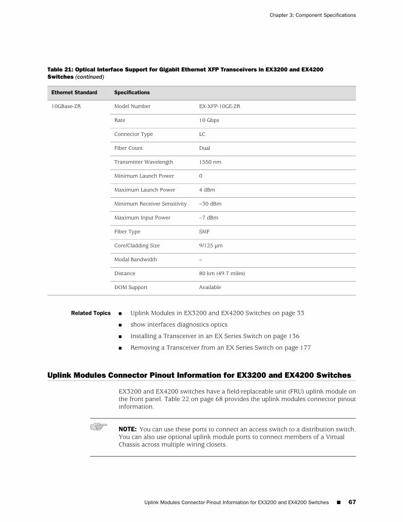
Table 21: Optical Interface Support for Gigabit Ethernet XFP Transceivers in EX3200 and EX4200Switches (continued)
SpecificationsEthernet Standard
EX-XFP-10GE-ZRModel Number10GBase-ZR
10 GbpsRate
LCConnector Type
DualFiber Count
1550 nmTransmitter Wavelength
0Minimum Launch Power
4 dBmMaximum Launch Power
–30 dBmMinimum Receiver Sensitivity
–7 dBmMaximum Input Power
SMFFiber Type
9/125 µmCore/Cladding Size
–Modal Bandwidth
80 km (49.7 miles)Distance
AvailableDOM Support
Related Topics ■ Uplink Modules in EX3200 and EX4200 Switches on page 33
■ show interfaces diagnostics optics
■ Installing a Transceiver in an EX Series Switch on page 136
■ Removing a Transceiver from an EX Series Switch on page 177
Uplink Modules Connector Pinout Information for EX3200 and EX4200 Switches
EX3200 and EX4200 switches have a field-replaceable unit (FRU) uplink module onthe front panel. Table 22 on page 68 provides the uplink modules connector pinoutinformation.
NOTE: You can use these ports to connect an access switch to a distribution switch.You can also use optional uplink module ports to connect members of a VirtualChassis across multiple wiring closets.
Uplink Modules Connector Pinout Information for EX3200 and EX4200 Switches ■ 67
Chapter 3: Component Specifications
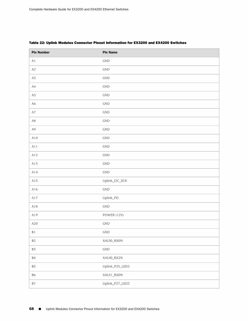
Table 22: Uplink Modules Connector Pinout Information for EX3200 and EX4200 Switches
Pin NamePin Number
GNDA1
GNDA2
GNDA3
GNDA4
GNDA5
GNDA6
GNDA7
GNDA8
GNDA9
GNDA10
GNDA11
GNDA12
GNDA13
GNDA14
Uplink_I2C_SCKA15
GNDA16
Uplink_PDA17
GNDA18
POWER (12V)A19
GNDA20
GNDB1
XAUI0_RX0NB2
GNDB3
XAUI0_RX2NB4
Uplink_P25_LED2B5
XAUI1_RX0NB6
Uplink_P27_LED2B7
68 ■ Uplink Modules Connector Pinout Information for EX3200 and EX4200 Switches
Complete Hardware Guide for EX3200 and EX4200 Ethernet Switches
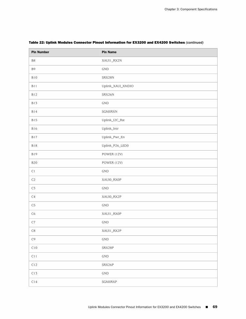
Table 22: Uplink Modules Connector Pinout Information for EX3200 and EX4200 Switches (continued)
Pin NamePin Number
XAUI1_RX2NB8
GNDB9
SRX28NB10
Uplink_XAUI_XMDIOB11
SRX26NB12
GNDB13
SGMIIRXNB14
Uplink_I2C_RstB15
Uplink_IntrB16
Uplink_Pwr_EnB17
Uplink_P26_LED0B18
POWER (12V)B19
POWER (12V)B20
GNDC1
XAUI0_RX0PC2
GNDC3
XAUI0_RX2PC4
GNDC5
XAUI1_RX0PC6
GNDC7
XAUI1_RX2PC8
GNDC9
SRX28PC10
GNDC11
SRX26PC12
GNDC13
SGMIIRXPC14
Uplink Modules Connector Pinout Information for EX3200 and EX4200 Switches ■ 69
Chapter 3: Component Specifications
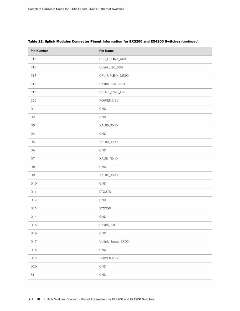
Table 22: Uplink Modules Connector Pinout Information for EX3200 and EX4200 Switches (continued)
Pin NamePin Number
CPU_UPLINK_MDCC15
Uplink_I2C_SDAC16
CPU_UPLINK_MDIOC17
Uplink_P26_LED1C18
UPLNK_PWR_OKC19
POWER (12V)C20
GNDD1
GNDD2
XAUI0_TX1ND3
GNDD4
XAUI0_TX3ND5
GNDD6
XAUI1_TX1ND7
GNDD8
XAUI1_TX3ND9
GNDD10
STX27ND11
GNDD12
STX25ND13
GNDD14
Uplink_RstD15
GNDD16
Uplink_Status_LED0D17
GNDD18
POWER (12V)D19
GNDD20
GNDE1
70 ■ Uplink Modules Connector Pinout Information for EX3200 and EX4200 Switches
Complete Hardware Guide for EX3200 and EX4200 Ethernet Switches
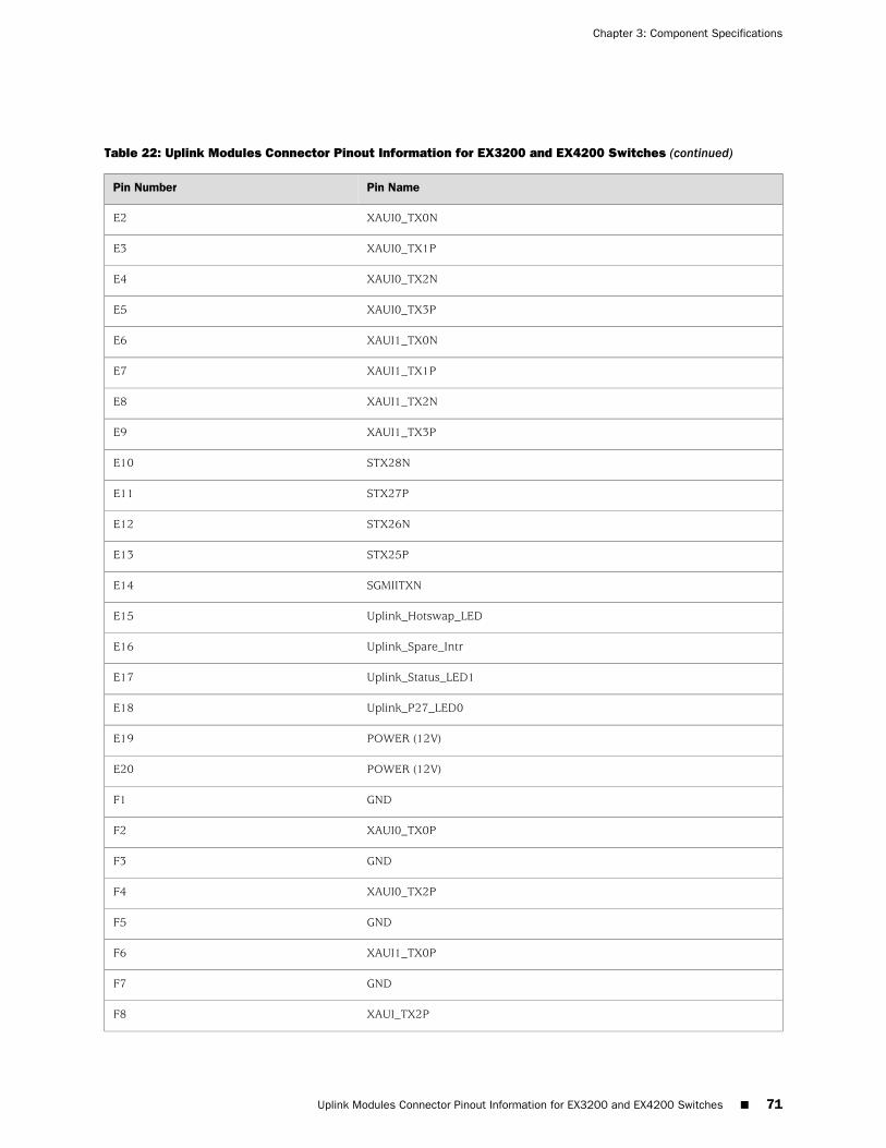
Table 22: Uplink Modules Connector Pinout Information for EX3200 and EX4200 Switches (continued)
Pin NamePin Number
XAUI0_TX0NE2
XAUI0_TX1PE3
XAUI0_TX2NE4
XAUI0_TX3PE5
XAUI1_TX0NE6
XAUI1_TX1PE7
XAUI1_TX2NE8
XAUI1_TX3PE9
STX28NE10
STX27PE11
STX26NE12
STX25PE13
SGMIITXNE14
Uplink_Hotswap_LEDE15
Uplink_Spare_IntrE16
Uplink_Status_LED1E17
Uplink_P27_LED0E18
POWER (12V)E19
POWER (12V)E20
GNDF1
XAUI0_TX0PF2
GNDF3
XAUI0_TX2PF4
GNDF5
XAUI1_TX0PF6
GNDF7
XAUI_TX2PF8
Uplink Modules Connector Pinout Information for EX3200 and EX4200 Switches ■ 71
Chapter 3: Component Specifications
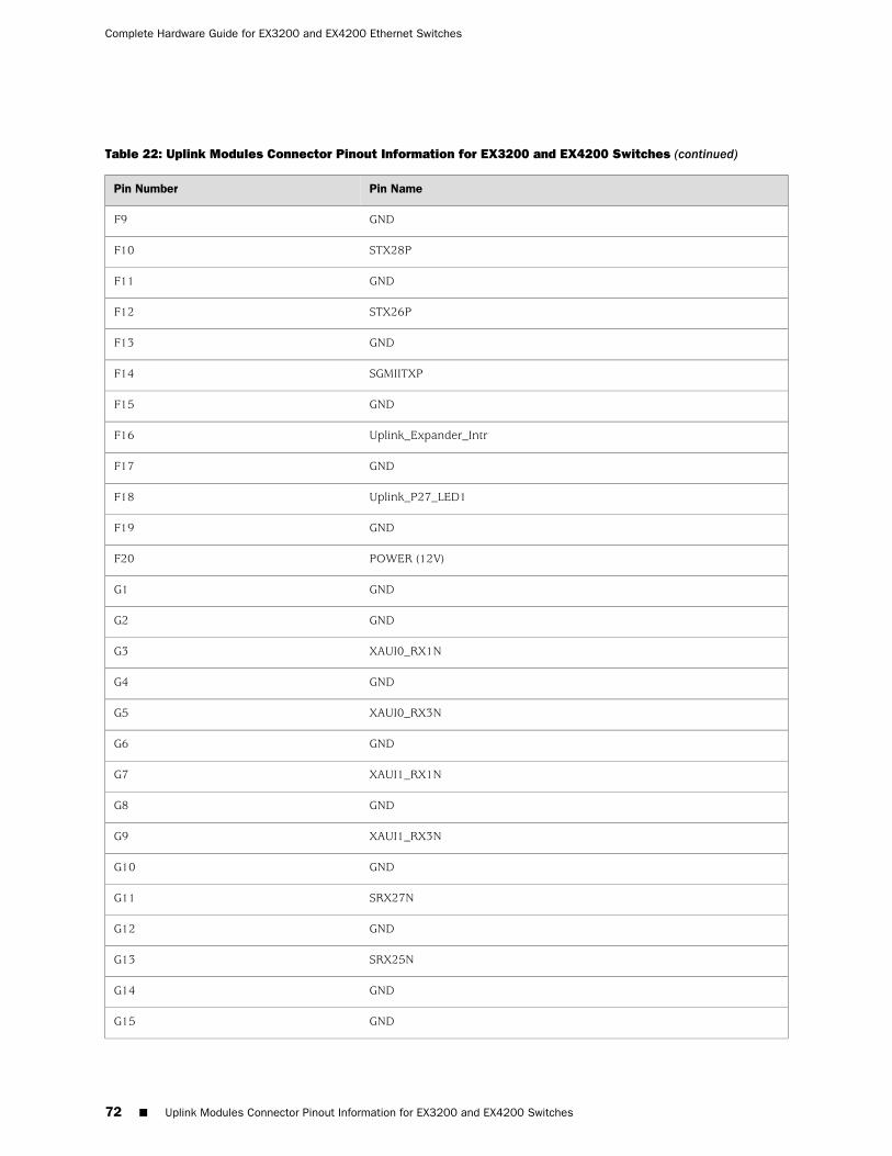
Table 22: Uplink Modules Connector Pinout Information for EX3200 and EX4200 Switches (continued)
Pin NamePin Number
GNDF9
STX28PF10
GNDF11
STX26PF12
GNDF13
SGMIITXPF14
GNDF15
Uplink_Expander_IntrF16
GNDF17
Uplink_P27_LED1F18
GNDF19
POWER (12V)F20
GNDG1
GNDG2
XAUI0_RX1NG3
GNDG4
XAUI0_RX3NG5
GNDG6
XAUI1_RX1NG7
GNDG8
XAUI1_RX3NG9
GNDG10
SRX27NG11
GNDG12
SRX25NG13
GNDG14
GNDG15
72 ■ Uplink Modules Connector Pinout Information for EX3200 and EX4200 Switches
Complete Hardware Guide for EX3200 and EX4200 Ethernet Switches
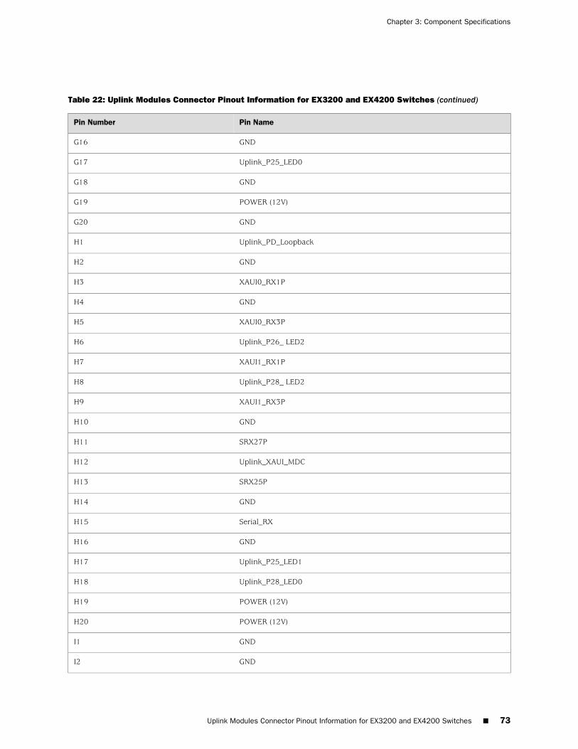
Table 22: Uplink Modules Connector Pinout Information for EX3200 and EX4200 Switches (continued)
Pin NamePin Number
GNDG16
Uplink_P25_LED0G17
GNDG18
POWER (12V)G19
GNDG20
Uplink_PD_LoopbackH1
GNDH2
XAUI0_RX1PH3
GNDH4
XAUI0_RX3PH5
Uplink_P26_ LED2H6
XAUI1_RX1PH7
Uplink_P28_ LED2H8
XAUI1_RX3PH9
GNDH10
SRX27PH11
Uplink_XAUI_MDCH12
SRX25PH13
GNDH14
Serial_RXH15
GNDH16
Uplink_P25_LED1H17
Uplink_P28_LED0H18
POWER (12V)H19
POWER (12V)H20
GNDI1
GNDI2
Uplink Modules Connector Pinout Information for EX3200 and EX4200 Switches ■ 73
Chapter 3: Component Specifications
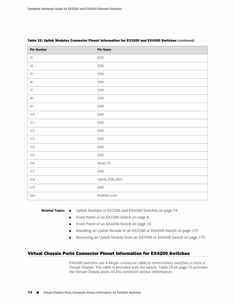
Table 22: Uplink Modules Connector Pinout Information for EX3200 and EX4200 Switches (continued)
Pin NamePin Number
GNDI3
GNDI4
GNDI5
GNDI6
GNDI7
GNDI8
GNDI9
GNDI10
GNDI11
GNDI12
GNDI13
GNDI14
GNDI15
Serial_TXI16
GNDI17
Uplink_P28_LED1I18
GNDI19
POWER (12V)I20
Related Topics ■ Uplink Modules in EX3200 and EX4200 Switches on page 33
■ Front Panel of an EX3200 Switch on page 8
■ Front Panel of an EX4200 Switch on page 10
■ Installing an Uplink Module in an EX3200 or EX4200 Switch on page 133
■ Removing an Uplink Module from an EX3200 or EX4200 Switch on page 175
Virtual Chassis Ports Connector Pinout Information for EX4200 Switches
EX4200 switches use a 68-pin connector cable to interconnect switches to form aVirtual Chassis. The cable is provided with the switch. Table 23 on page 75 providesthe Virtual Chassis ports (VCPs) connector pinout information.
74 ■ Virtual Chassis Ports Connector Pinout Information for EX4200 Switches
Complete Hardware Guide for EX3200 and EX4200 Ethernet Switches
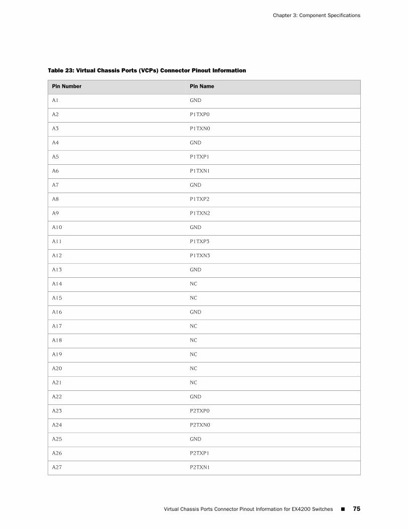
Table 23: Virtual Chassis Ports (VCPs) Connector Pinout Information
Pin NamePin Number
GNDA1
P1TXP0A2
P1TXN0A3
GNDA4
P1TXP1A5
P1TXN1A6
GNDA7
P1TXP2A8
P1TXN2A9
GNDA10
P1TXP3A11
P1TXN3A12
GNDA13
NCA14
NCA15
GNDA16
NCA17
NCA18
NCA19
NCA20
NCA21
GNDA22
P2TXP0A23
P2TXN0A24
GNDA25
P2TXP1A26
P2TXN1A27
Virtual Chassis Ports Connector Pinout Information for EX4200 Switches ■ 75
Chapter 3: Component Specifications
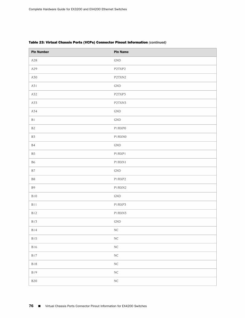
Table 23: Virtual Chassis Ports (VCPs) Connector Pinout Information (continued)
Pin NamePin Number
GNDA28
P2TXP2A29
P2TXN2A30
GNDA31
P2TXP3A32
P2TXN3A33
GNDA34
GNDB1
P1RXP0B2
P1RXN0B3
GNDB4
P1RXP1B5
P1RXN1B6
GNDB7
P1RXP2B8
P1RXN2B9
GNDB10
P1RXP3B11
P1RXN3B12
GNDB13
NCB14
NCB15
NCB16
NCB17
NCB18
NCB19
NCB20
76 ■ Virtual Chassis Ports Connector Pinout Information for EX4200 Switches
Complete Hardware Guide for EX3200 and EX4200 Ethernet Switches
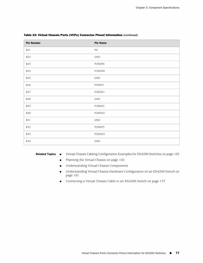
Table 23: Virtual Chassis Ports (VCPs) Connector Pinout Information (continued)
Pin NamePin Number
NCB21
GNDB22
P2RXP0B23
P2RXN0B24
GNDB25
P2RXP1B26
P2RXN1B27
GNDB28
P2RXP2B29
P2RXN2B30
GNDB31
P2RXP3B32
P2RXN3B33
GNDB34
Related Topics ■ Virtual Chassis Cabling Configuration Examples for EX4200 Switches on page 103
■ Planning the Virtual Chassis on page 102
■ Understanding Virtual Chassis Components
■ Understanding Virtual Chassis Hardware Configuration on an EX4200 Switch onpage 101
■ Connecting a Virtual Chassis Cable to an EX4200 Switch on page 137
Virtual Chassis Ports Connector Pinout Information for EX4200 Switches ■ 77
Chapter 3: Component Specifications

78 ■ Virtual Chassis Ports Connector Pinout Information for EX4200 Switches
Complete Hardware Guide for EX3200 and EX4200 Ethernet Switches

Part 2
Planning for Switch Installation
■ Site Preparation on page 81
■ Mounting and Clearance Requirements on page 87
■ Cable Specifications on page 95
■ Planning Power Requirements on page 97
■ Planning the Virtual Chassis on page 101
Planning for Switch Installation ■ 79

80 ■ Planning for Switch Installation
Complete Hardware Guide for EX3200 and EX4200 Ethernet Switches
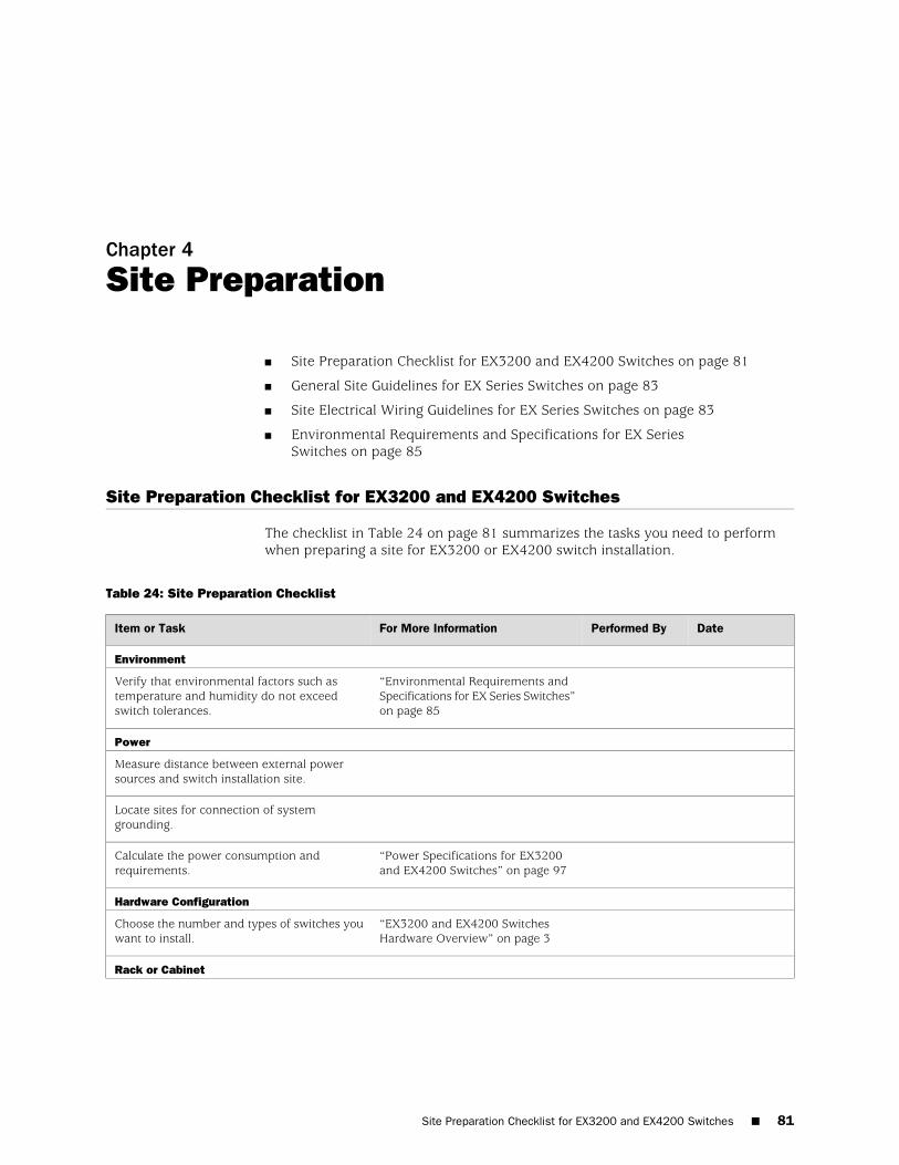
Chapter 4
Site Preparation
■ Site Preparation Checklist for EX3200 and EX4200 Switches on page 81
■ General Site Guidelines for EX Series Switches on page 83
■ Site Electrical Wiring Guidelines for EX Series Switches on page 83
■ Environmental Requirements and Specifications for EX SeriesSwitches on page 85
Site Preparation Checklist for EX3200 and EX4200 Switches
The checklist in Table 24 on page 81 summarizes the tasks you need to performwhen preparing a site for EX3200 or EX4200 switch installation.
Table 24: Site Preparation Checklist
DatePerformed ByFor More InformationItem or Task
Environment
“Environmental Requirements andSpecifications for EX Series Switches”on page 85
Verify that environmental factors such astemperature and humidity do not exceedswitch tolerances.
Power
Measure distance between external powersources and switch installation site.
Locate sites for connection of systemgrounding.
“Power Specifications for EX3200and EX4200 Switches” on page 97
Calculate the power consumption andrequirements.
Hardware Configuration
“EX3200 and EX4200 SwitchesHardware Overview” on page 3
Choose the number and types of switches youwant to install.
Rack or Cabinet
Site Preparation Checklist for EX3200 and EX4200 Switches ■ 81
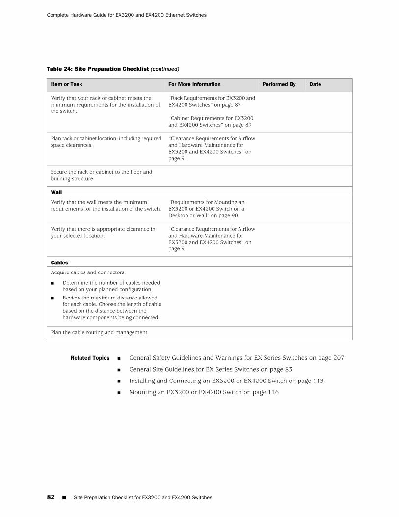
Table 24: Site Preparation Checklist (continued)
DatePerformed ByFor More InformationItem or Task
“Rack Requirements for EX3200 andEX4200 Switches” on page 87
“Cabinet Requirements for EX3200and EX4200 Switches” on page 89
Verify that your rack or cabinet meets theminimum requirements for the installation ofthe switch.
“Clearance Requirements for Airflowand Hardware Maintenance forEX3200 and EX4200 Switches” onpage 91
Plan rack or cabinet location, including requiredspace clearances.
Secure the rack or cabinet to the floor andbuilding structure.
Wall
“Requirements for Mounting anEX3200 or EX4200 Switch on aDesktop or Wall” on page 90
Verify that the wall meets the minimumrequirements for the installation of the switch.
“Clearance Requirements for Airflowand Hardware Maintenance forEX3200 and EX4200 Switches” onpage 91
Verify that there is appropriate clearance inyour selected location.
Cables
Acquire cables and connectors:
■ Determine the number of cables neededbased on your planned configuration.
■ Review the maximum distance allowedfor each cable. Choose the length of cablebased on the distance between thehardware components being connected.
Plan the cable routing and management.
Related Topics ■ General Safety Guidelines and Warnings for EX Series Switches on page 207
■ General Site Guidelines for EX Series Switches on page 83
■ Installing and Connecting an EX3200 or EX4200 Switch on page 113
■ Mounting an EX3200 or EX4200 Switch on page 116
82 ■ Site Preparation Checklist for EX3200 and EX4200 Switches
Complete Hardware Guide for EX3200 and EX4200 Ethernet Switches

General Site Guidelines for EX Series Switches
Efficient switch operation requires proper site planning and maintenance, and properlayout of the equipment, rack or cabinet (if used), and wiring closet.
To plan and create an acceptable operating environment for your EX Series switchand prevent environmentally caused equipment failures:
■ Keep the area around the chassis free from dust and conductive material, suchas metal flakes.
■ Follow prescribed airflow guidelines to ensure that the cooling system functionsproperly and that exhaust from other equipment does not blow into the intakevents of the switch.
■ Follow the prescribed ESD prevention procedures to avoid damaging theequipment. Static discharge can cause components to fail completely orintermittently over time.
■ Install the switch in a secure area, so that only authorized personnel can accessthe switch.
Related Topics ■ Prevention of Electrostatic Discharge Damage on EX Series Switches on page 236
■ Clearance Requirements for Airflow and Hardware Maintenance for EX2200Switches
■ Clearance Requirements for Airflow and Hardware Maintenance for EX3200 andEX4200 Switches on page 91
■ Clearance Requirements for Airflow and Hardware Maintenance for an EX8208Switch
■ Clearance Requirements for Airflow and Hardware Maintenance for an EX8216Switch
■ Environmental Requirements and Specifications for EX Series Switches onpage 85
■ Installing and Connecting an EX2200 Switch
■ Installing and Connecting an EX3200 or EX4200 Switch on page 113
■ Installing and Connecting an EX8208 Switch
■ Installing and Connecting an EX8216 Switch
Site Electrical Wiring Guidelines for EX Series Switches
Table 25 on page 84 describes the factors you must consider while planning theelectrical wiring at your site.
General Site Guidelines for EX Series Switches ■ 83
Chapter 4: Site Preparation
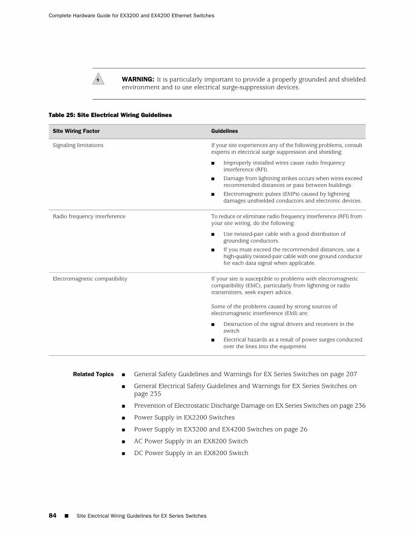
WARNING: It is particularly important to provide a properly grounded and shieldedenvironment and to use electrical surge-suppression devices.
Table 25: Site Electrical Wiring Guidelines
GuidelinesSite Wiring Factor
If your site experiences any of the following problems, consultexperts in electrical surge suppression and shielding:
■ Improperly installed wires cause radio frequencyinterference (RFI).
■ Damage from lightning strikes occurs when wires exceedrecommended distances or pass between buildings.
■ Electromagnetic pulses (EMPs) caused by lightningdamages unshielded conductors and electronic devices.
Signaling limitations
To reduce or eliminate radio frequency interference (RFI) fromyour site wiring, do the following:
■ Use twisted-pair cable with a good distribution ofgrounding conductors.
■ If you must exceed the recommended distances, use ahigh-quality twisted-pair cable with one ground conductorfor each data signal when applicable.
Radio frequency interference
If your site is susceptible to problems with electromagneticcompatibility (EMC), particularly from lightning or radiotransmitters, seek expert advice.
Some of the problems caused by strong sources ofelectromagnetic interference (EMI) are:
■ Destruction of the signal drivers and receivers in theswitch
■ Electrical hazards as a result of power surges conductedover the lines into the equipment
Electromagnetic compatibility
Related Topics ■ General Safety Guidelines and Warnings for EX Series Switches on page 207
■ General Electrical Safety Guidelines and Warnings for EX Series Switches onpage 235
■ Prevention of Electrostatic Discharge Damage on EX Series Switches on page 236
■ Power Supply in EX2200 Switches
■ Power Supply in EX3200 and EX4200 Switches on page 26
■ AC Power Supply in an EX8200 Switch
■ DC Power Supply in an EX8200 Switch
84 ■ Site Electrical Wiring Guidelines for EX Series Switches
Complete Hardware Guide for EX3200 and EX4200 Ethernet Switches
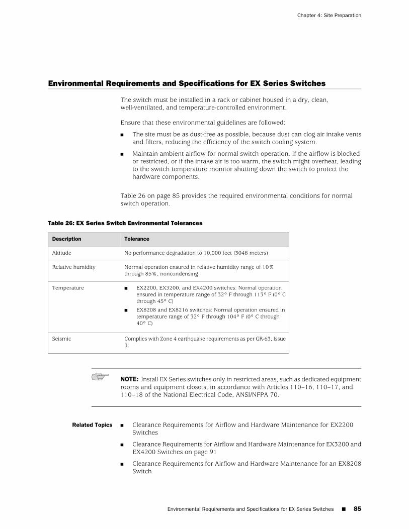
Environmental Requirements and Specifications for EX Series Switches
The switch must be installed in a rack or cabinet housed in a dry, clean,well-ventilated, and temperature-controlled environment.
Ensure that these environmental guidelines are followed:
■ The site must be as dust-free as possible, because dust can clog air intake ventsand filters, reducing the efficiency of the switch cooling system.
■ Maintain ambient airflow for normal switch operation. If the airflow is blockedor restricted, or if the intake air is too warm, the switch might overheat, leadingto the switch temperature monitor shutting down the switch to protect thehardware components.
Table 26 on page 85 provides the required environmental conditions for normalswitch operation.
Table 26: EX Series Switch Environmental Tolerances
ToleranceDescription
No performance degradation to 10,000 feet (3048 meters)Altitude
Normal operation ensured in relative humidity range of 10%through 85%, noncondensing
Relative humidity
■ EX2200, EX3200, and EX4200 switches: Normal operationensured in temperature range of 32° F through 113° F (0° Cthrough 45° C)
■ EX8208 and EX8216 switches: Normal operation ensured intemperature range of 32° F through 104° F (0° C through40° C)
Temperature
Complies with Zone 4 earthquake requirements as per GR-63, Issue3.
Seismic
NOTE: Install EX Series switches only in restricted areas, such as dedicated equipmentrooms and equipment closets, in accordance with Articles 110–16, 110–17, and110–18 of the National Electrical Code, ANSI/NFPA 70.
Related Topics ■ Clearance Requirements for Airflow and Hardware Maintenance for EX2200Switches
■ Clearance Requirements for Airflow and Hardware Maintenance for EX3200 andEX4200 Switches on page 91
■ Clearance Requirements for Airflow and Hardware Maintenance for an EX8208Switch
Environmental Requirements and Specifications for EX Series Switches ■ 85
Chapter 4: Site Preparation

■ Clearance Requirements for Airflow and Hardware Maintenance for an EX8216Switch
■ Installing and Connecting an EX2200 Switch
■ Installing and Connecting an EX3200 or EX4200 Switch on page 113
■ Installing and Connecting an EX8208 Switch
■ Installing and Connecting an EX8216 Switch
86 ■ Environmental Requirements and Specifications for EX Series Switches
Complete Hardware Guide for EX3200 and EX4200 Ethernet Switches

Chapter 5
Mounting and Clearance Requirements
■ Rack Requirements for EX3200 and EX4200 Switches on page 87
■ Cabinet Requirements for EX3200 and EX4200 Switches on page 89
■ Requirements for Mounting an EX3200 or EX4200 Switch on a Desktop orWall on page 90
■ Clearance Requirements for Airflow and Hardware Maintenance for EX3200 andEX4200 Switches on page 91
Rack Requirements for EX3200 and EX4200 Switches
You can mount the switch on two-post racks or four-post racks.
Rack requirements consist of:
■ Rack type
■ Mounting bracket hole spacing
■ Rack size and strength
■ Rack connection to the building structure
Table 27 on page 87 provides the rack requirements and specifications for the switch.
Table 27: Rack Requirements and Specifications for the Switch
GuidelinesRack Requirement
Use a four-post rack or a two-post rack. You can mount the switch on any four-post or two-post rackthat provides bracket holes or hole patterns spaced at 1 U (1.75 in./4.45 cm) increments and that meetsthe size and strength requirements to support the weight.
A U is the standard rack unit defined in Cabinets, Racks, Panels, and Associated Equipment (documentnumber EIA-310–D) published by the Electronics Industry Association (http://www.eia.org).
With adequate cooling air and airflow clearance, you can mount 42 switches in a four-post rack or atwo-post rack that has a height of at least 42 U. In all cases, the rack must meet the strength requirementsto support the weight.
Rack type
The holes in the mounting brackets are spaced at 1 U (1.75 in. or 4.45 cm), so that the switch can bemounted in any rack that provides holes spaced at that distance.
Mounting brackethole spacing
Rack Requirements for EX3200 and EX4200 Switches ■ 87
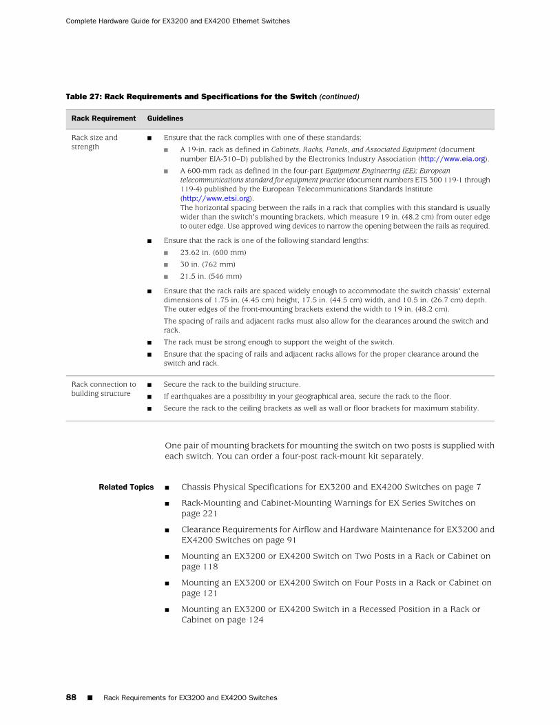
Table 27: Rack Requirements and Specifications for the Switch (continued)
GuidelinesRack Requirement
■ Ensure that the rack complies with one of these standards:
■ A 19-in. rack as defined in Cabinets, Racks, Panels, and Associated Equipment (documentnumber EIA-310–D) published by the Electronics Industry Association (http://www.eia.org).
■ A 600-mm rack as defined in the four-part Equipment Engineering (EE); Europeantelecommunications standard for equipment practice (document numbers ETS 300 119-1 through119-4) published by the European Telecommunications Standards Institute(http://www.etsi.org).The horizontal spacing between the rails in a rack that complies with this standard is usuallywider than the switch's mounting brackets, which measure 19 in. (48.2 cm) from outer edgeto outer edge. Use approved wing devices to narrow the opening between the rails as required.
■ Ensure that the rack is one of the following standard lengths:
■ 23.62 in. (600 mm)
■ 30 in. (762 mm)
■ 21.5 in. (546 mm)
■ Ensure that the rack rails are spaced widely enough to accommodate the switch chassis' externaldimensions of 1.75 in. (4.45 cm) height, 17.5 in. (44.5 cm) width, and 10.5 in. (26.7 cm) depth.The outer edges of the front-mounting brackets extend the width to 19 in. (48.2 cm).
The spacing of rails and adjacent racks must also allow for the clearances around the switch andrack.
■ The rack must be strong enough to support the weight of the switch.
■ Ensure that the spacing of rails and adjacent racks allows for the proper clearance around theswitch and rack.
Rack size andstrength
■ Secure the rack to the building structure.
■ If earthquakes are a possibility in your geographical area, secure the rack to the floor.
■ Secure the rack to the ceiling brackets as well as wall or floor brackets for maximum stability.
Rack connection tobuilding structure
One pair of mounting brackets for mounting the switch on two posts is supplied witheach switch. You can order a four-post rack-mount kit separately.
Related Topics ■ Chassis Physical Specifications for EX3200 and EX4200 Switches on page 7
■ Rack-Mounting and Cabinet-Mounting Warnings for EX Series Switches onpage 221
■ Clearance Requirements for Airflow and Hardware Maintenance for EX3200 andEX4200 Switches on page 91
■ Mounting an EX3200 or EX4200 Switch on Two Posts in a Rack or Cabinet onpage 118
■ Mounting an EX3200 or EX4200 Switch on Four Posts in a Rack or Cabinet onpage 121
■ Mounting an EX3200 or EX4200 Switch in a Recessed Position in a Rack orCabinet on page 124
88 ■ Rack Requirements for EX3200 and EX4200 Switches
Complete Hardware Guide for EX3200 and EX4200 Ethernet Switches
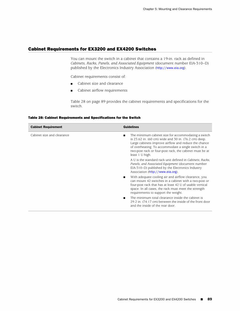
Cabinet Requirements for EX3200 and EX4200 Switches
You can mount the switch in a cabinet that contains a 19-in. rack as defined inCabinets, Racks, Panels, and Associated Equipment (document number EIA-310–D)published by the Electronics Industry Association (http://www.eia.org).
Cabinet requirements consist of:
■ Cabinet size and clearance
■ Cabinet airflow requirements
Table 28 on page 89 provides the cabinet requirements and specifications for theswitch.
Table 28: Cabinet Requirements and Specifications for the Switch
GuidelinesCabinet Requirement
■ The minimum cabinet size for accommodating a switchis 23.62 in. (60 cm) wide and 30 in. (76.2 cm) deep.Large cabinets improve airflow and reduce the chanceof overheating. To accommodate a single switch in atwo-post rack or four-post rack, the cabinet must be atleast 1 U high.
A U is the standard rack unit defined in Cabinets, Racks,Panels, and Associated Equipment (document numberEIA-310–D) published by the Electronics IndustryAssociation (http://www.eia.org).
■ With adequate cooling air and airflow clearance, youcan mount 42 switches in a cabinet with a two-post orfour-post rack that has at least 42 U of usable verticalspace. In all cases, the rack must meet the strengthrequirements to support the weight.
■ The minimum total clearance inside the cabinet is29.2 in. (74.17 cm) between the inside of the front doorand the inside of the rear door.
Cabinet size and clearance
Cabinet Requirements for EX3200 and EX4200 Switches ■ 89
Chapter 5: Mounting and Clearance Requirements
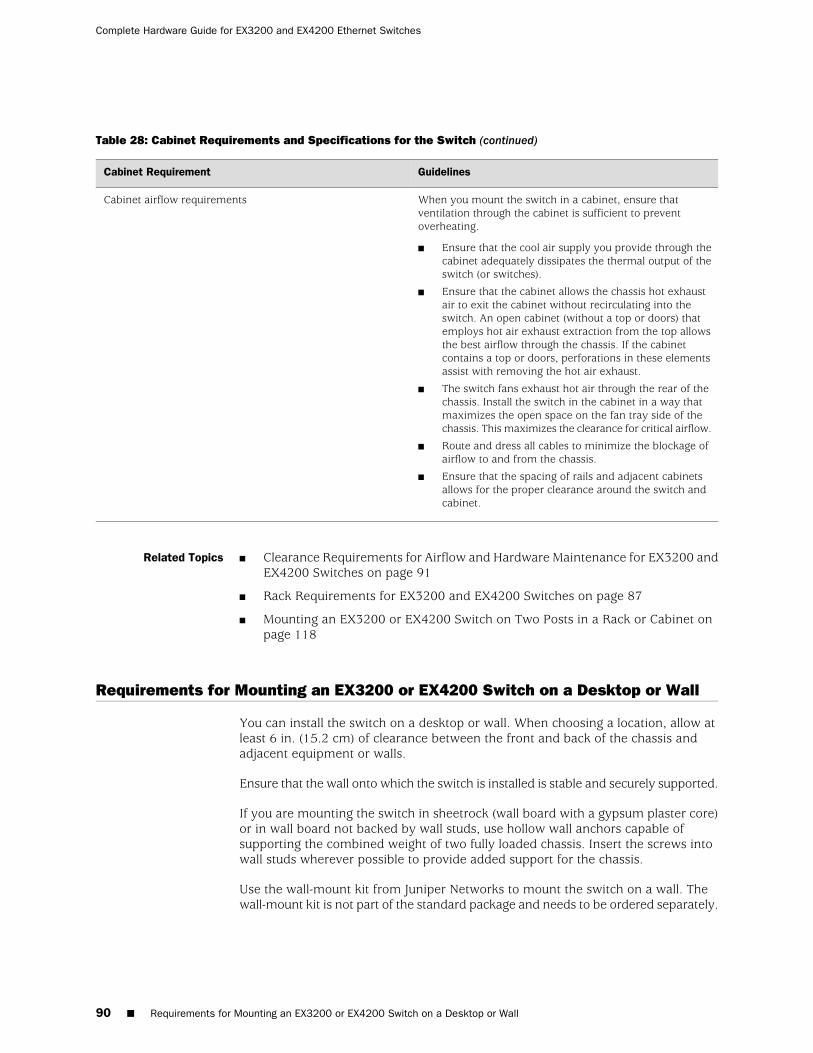
Table 28: Cabinet Requirements and Specifications for the Switch (continued)
GuidelinesCabinet Requirement
When you mount the switch in a cabinet, ensure thatventilation through the cabinet is sufficient to preventoverheating.
■ Ensure that the cool air supply you provide through thecabinet adequately dissipates the thermal output of theswitch (or switches).
■ Ensure that the cabinet allows the chassis hot exhaustair to exit the cabinet without recirculating into theswitch. An open cabinet (without a top or doors) thatemploys hot air exhaust extraction from the top allowsthe best airflow through the chassis. If the cabinetcontains a top or doors, perforations in these elementsassist with removing the hot air exhaust.
■ The switch fans exhaust hot air through the rear of thechassis. Install the switch in the cabinet in a way thatmaximizes the open space on the fan tray side of thechassis. This maximizes the clearance for critical airflow.
■ Route and dress all cables to minimize the blockage ofairflow to and from the chassis.
■ Ensure that the spacing of rails and adjacent cabinetsallows for the proper clearance around the switch andcabinet.
Cabinet airflow requirements
Related Topics Clearance Requirements for Airflow and Hardware Maintenance for EX3200 andEX4200 Switches on page 91
■
■ Rack Requirements for EX3200 and EX4200 Switches on page 87
■ Mounting an EX3200 or EX4200 Switch on Two Posts in a Rack or Cabinet onpage 118
Requirements for Mounting an EX3200 or EX4200 Switch on a Desktop or Wall
You can install the switch on a desktop or wall. When choosing a location, allow atleast 6 in. (15.2 cm) of clearance between the front and back of the chassis andadjacent equipment or walls.
Ensure that the wall onto which the switch is installed is stable and securely supported.
If you are mounting the switch in sheetrock (wall board with a gypsum plaster core)or in wall board not backed by wall studs, use hollow wall anchors capable ofsupporting the combined weight of two fully loaded chassis. Insert the screws intowall studs wherever possible to provide added support for the chassis.
Use the wall-mount kit from Juniper Networks to mount the switch on a wall. Thewall-mount kit is not part of the standard package and needs to be ordered separately.
90 ■ Requirements for Mounting an EX3200 or EX4200 Switch on a Desktop or Wall
Complete Hardware Guide for EX3200 and EX4200 Ethernet Switches
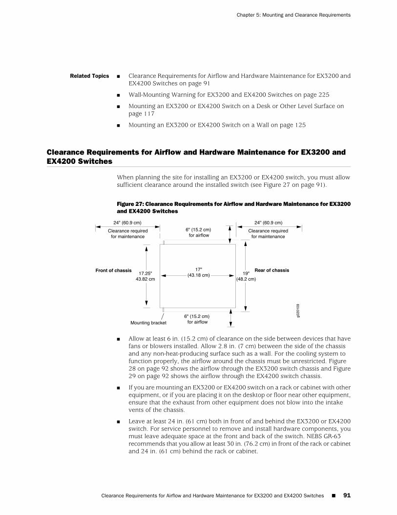
Related Topics ■ Clearance Requirements for Airflow and Hardware Maintenance for EX3200 andEX4200 Switches on page 91
■ Wall-Mounting Warning for EX3200 and EX4200 Switches on page 225
■ Mounting an EX3200 or EX4200 Switch on a Desk or Other Level Surface onpage 117
■ Mounting an EX3200 or EX4200 Switch on a Wall on page 125
Clearance Requirements for Airflow and Hardware Maintenance for EX3200 andEX4200 Switches
When planning the site for installing an EX3200 or EX4200 switch, you must allowsufficient clearance around the installed switch (see Figure 27 on page 91).
Figure 27: Clearance Requirements for Airflow and Hardware Maintenance for EX3200and EX4200 Switches
■ Allow at least 6 in. (15.2 cm) of clearance on the side between devices that havefans or blowers installed. Allow 2.8 in. (7 cm) between the side of the chassisand any non-heat-producing surface such as a wall. For the cooling system tofunction properly, the airflow around the chassis must be unrestricted. Figure28 on page 92 shows the airflow through the EX3200 switch chassis and Figure29 on page 92 shows the airflow through the EX4200 switch chassis.
■ If you are mounting an EX3200 or EX4200 switch on a rack or cabinet with otherequipment, or if you are placing it on the desktop or floor near other equipment,ensure that the exhaust from other equipment does not blow into the intakevents of the chassis.
■ Leave at least 24 in. (61 cm) both in front of and behind the EX3200 or EX4200switch. For service personnel to remove and install hardware components, youmust leave adequate space at the front and back of the switch. NEBS GR-63recommends that you allow at least 30 in. (76.2 cm) in front of the rack or cabinetand 24 in. (61 cm) behind the rack or cabinet.
Clearance Requirements for Airflow and Hardware Maintenance for EX3200 and EX4200 Switches ■ 91
Chapter 5: Mounting and Clearance Requirements
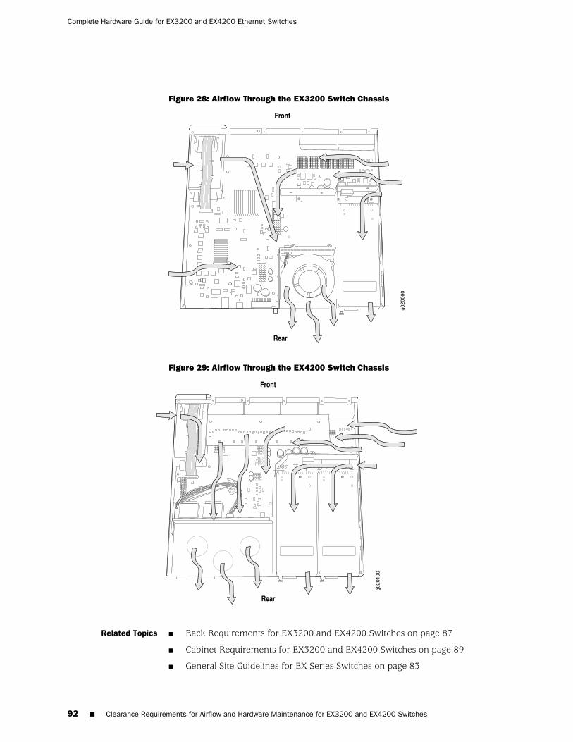
Figure 28: Airflow Through the EX3200 Switch Chassis
Figure 29: Airflow Through the EX4200 Switch Chassis
Related Topics ■ Rack Requirements for EX3200 and EX4200 Switches on page 87
■ Cabinet Requirements for EX3200 and EX4200 Switches on page 89
■ General Site Guidelines for EX Series Switches on page 83
92 ■ Clearance Requirements for Airflow and Hardware Maintenance for EX3200 and EX4200 Switches
Complete Hardware Guide for EX3200 and EX4200 Ethernet Switches

■ Rack-Mounting and Cabinet-Mounting Warnings for EX Series Switches onpage 221
■ Cooling System and Airflow in an EX3200 Switch on page 31
■ Cooling System and Airflow in an EX4200 Switch on page 32
Clearance Requirements for Airflow and Hardware Maintenance for EX3200 and EX4200 Switches ■ 93
Chapter 5: Mounting and Clearance Requirements

94 ■ Clearance Requirements for Airflow and Hardware Maintenance for EX3200 and EX4200 Switches
Complete Hardware Guide for EX3200 and EX4200 Ethernet Switches

Chapter 6
Cable Specifications
■ Network Cable Specifications for EX3200 and EX4200 Switches on page 95
Network Cable Specifications for EX3200 and EX4200 Switches
EX3200 and EX4200 switches have interfaces that use various types of networkcables.
For instructions on connecting an EX3200 or EX4200 switch to a network forout-of-band management using an Ethernet cable with an RJ-45 connector, see“Connecting an EX Series Switch to a Network for Out-of-Band Management” onpage 152.
For instructions on connecting an EX3200 or EX4200 switch to a managementconsole using an Ethernet cable with an RJ-45 connector, see “Connecting an EXSeries Switch to a Management Console” on page 153.
Related Topics ■ Management Port Connector Pinout Information for an EX3200 or EX4200Switch on page 42
■ Console Port Connector Pinout Information for an EX Series Switch on page 41
■ Rear Panel of an EX3200 Switch on page 9
■ Rear Panel of an EX4200 Switch on page 11
Network Cable Specifications for EX3200 and EX4200 Switches ■ 95

96 ■ Network Cable Specifications for EX3200 and EX4200 Switches
Complete Hardware Guide for EX3200 and EX4200 Ethernet Switches
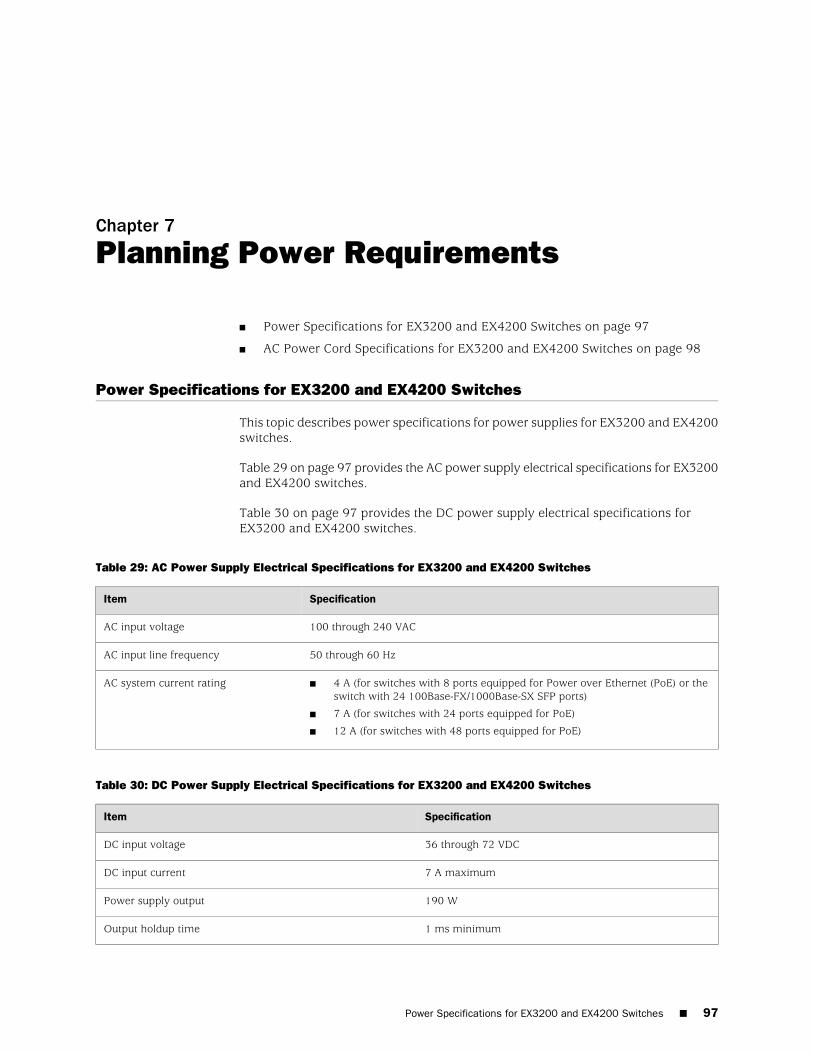
Chapter 7
Planning Power Requirements
■ Power Specifications for EX3200 and EX4200 Switches on page 97
■ AC Power Cord Specifications for EX3200 and EX4200 Switches on page 98
Power Specifications for EX3200 and EX4200 Switches
This topic describes power specifications for power supplies for EX3200 and EX4200switches.
Table 29 on page 97 provides the AC power supply electrical specifications for EX3200and EX4200 switches.
Table 30 on page 97 provides the DC power supply electrical specifications forEX3200 and EX4200 switches.
Table 29: AC Power Supply Electrical Specifications for EX3200 and EX4200 Switches
SpecificationItem
100 through 240 VACAC input voltage
50 through 60 HzAC input line frequency
■ 4 A (for switches with 8 ports equipped for Power over Ethernet (PoE) or theswitch with 24 100Base-FX/1000Base-SX SFP ports)
■ 7 A (for switches with 24 ports equipped for PoE)
■ 12 A (for switches with 48 ports equipped for PoE)
AC system current rating
Table 30: DC Power Supply Electrical Specifications for EX3200 and EX4200 Switches
SpecificationItem
36 through 72 VDCDC input voltage
7 A maximumDC input current
190 WPower supply output
1 ms minimumOutput holdup time
Power Specifications for EX3200 and EX4200 Switches ■ 97
NOTE: The DC power supply in EX3200 and EX4200 switches does not supportPower over Ethernet (PoE); you can use either an external power injector or an ACpower supply to supply power to PoE devices that you connect to the switch.
NOTE: For DC power supplies, we recommend that you provide at least 7.5 A @48 VDC and use a facility circuit breaker rated for 10 A minimum. Doing so enablesyou to operate the switch in any configuration without upgrading the powerinfrastructure, and allows the switch to function at full capacity using multiple powersupplies.
Related Topics ■ AC Power Cord Specifications for EX3200 and EX4200 Switches on page 98
■ Power Supply in EX3200 and EX4200 Switches on page 26
■ General Safety Guidelines and Warnings for EX Series Switches on page 207
■ General Electrical Safety Guidelines and Warnings for EX Series Switches onpage 235
AC Power Cord Specifications for EX3200 and EX4200 Switches
Detachable AC power cords are supplied with the switch. The coupler is type C13 asdescribed by International Electrotechnical Commission (IEC) standard 60320. Theplug at the male end of the power cord fits into the power source outlet that isstandard for your geographical location.
CAUTION: The AC power cord for the switches is intended for use with that switchonly and not for any other use.
NOTE: In North America, AC power cords must not exceed 4.5 meters (approximately14.75 feet) in length, to comply with National Electrical Code (NEC) Sections 400-8(NFPA 75, 5-2.2) and 210-52 and Canadian Electrical Code (CEC) Section 4-010(3).The cords supplied with the switch are in compliance.
Table 31 on page 98 lists AC power cord specifications provided for each country orregion.
Table 31: AC Power Cord Specifications
Plug StandardsElectrical SpecificationsCountry/Region
AS/NZ 3112–1993250 VAC, 10 A, 50 HzAustralia
98 ■ AC Power Cord Specifications for EX3200 and EX4200 Switches
Complete Hardware Guide for EX3200 and EX4200 Ethernet Switches
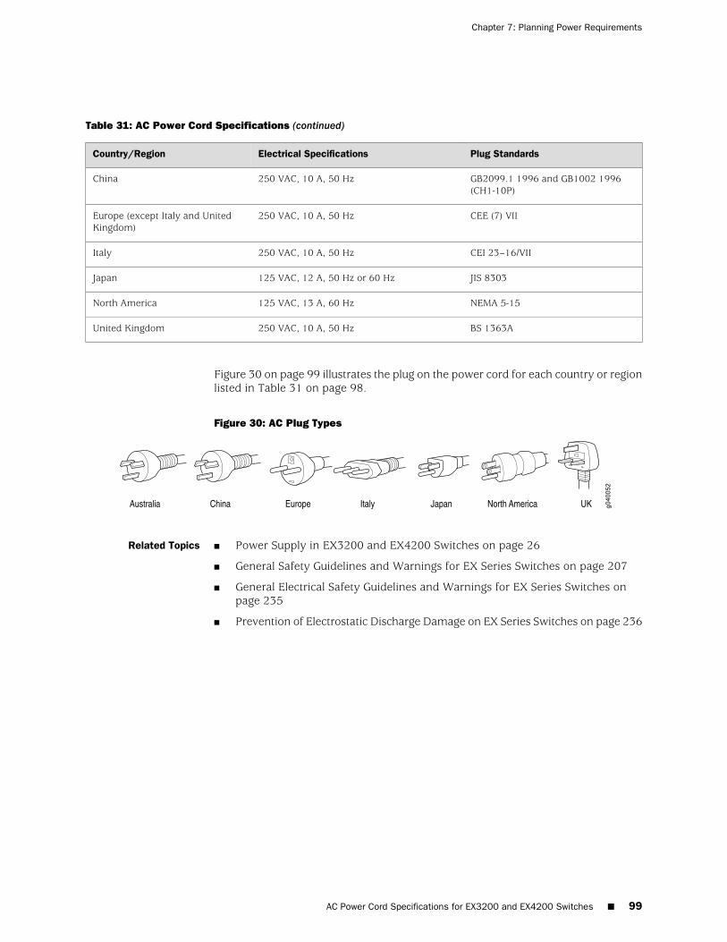
Table 31: AC Power Cord Specifications (continued)
Plug StandardsElectrical SpecificationsCountry/Region
GB2099.1 1996 and GB1002 1996(CH1-10P)
250 VAC, 10 A, 50 HzChina
CEE (7) VII250 VAC, 10 A, 50 HzEurope (except Italy and UnitedKingdom)
CEI 23–16/VII250 VAC, 10 A, 50 HzItaly
JIS 8303125 VAC, 12 A, 50 Hz or 60 HzJapan
NEMA 5-15125 VAC, 13 A, 60 HzNorth America
BS 1363A250 VAC, 10 A, 50 HzUnited Kingdom
Figure 30 on page 99 illustrates the plug on the power cord for each country or regionlisted in Table 31 on page 98.
Figure 30: AC Plug Types
Related Topics ■ Power Supply in EX3200 and EX4200 Switches on page 26
■ General Safety Guidelines and Warnings for EX Series Switches on page 207
■ General Electrical Safety Guidelines and Warnings for EX Series Switches onpage 235
■ Prevention of Electrostatic Discharge Damage on EX Series Switches on page 236
AC Power Cord Specifications for EX3200 and EX4200 Switches ■ 99
Chapter 7: Planning Power Requirements

100 ■ AC Power Cord Specifications for EX3200 and EX4200 Switches
Complete Hardware Guide for EX3200 and EX4200 Ethernet Switches
Chapter 8
Planning the Virtual Chassis
■ Understanding Virtual Chassis Hardware Configuration on an EX4200Switch on page 101
■ Planning the Virtual Chassis on page 102
■ Virtual Chassis Cabling Configuration Examples for EX4200 Switches on page 103
■ Adding a New Switch to an Existing Virtual Chassis Configuration (CLIProcedure) on page 105
Understanding Virtual Chassis Hardware Configuration on an EX4200 Switch
Virtual Chassis is a feature in Juniper Networks EX4200 Ethernet Switches that allowsyou to interconnect two or more EX4200 switches, enabling them to operate as aunified single high bandwidth switch. You can interconnect a maximum of 10 EX4200switches through the dedicated 64-Gbps Virtual Chassis ports (VCPs) or the uplinkmodule ports configured as VCPs to form a Virtual Chassis. All EX4200 switch modelssupport Virtual Chassis, and you can interconnect different models, offering a rangeof port configurations, within the same Virtual Chassis.
The Virtual Chassis configuration includes designation of a master switch and abackup switch, with all other switches in the configuration designated as "line card"role switches. Virtual Chassis operation is managed through the master switch. Eachswitch in the Virtual Chassis is assigned a unique identifier that is displayed on theswitch LCD.
Related Topics ■ Understanding Virtual Chassis Components
■ Planning the Virtual Chassis on page 102
■ Virtual Chassis Ports Connector Pinout Information for EX4200 Switches onpage 74
■ Virtual Chassis Cabling Configuration Examples for EX4200 Switches on page 103
Understanding Virtual Chassis Hardware Configuration on an EX4200 Switch ■ 101
Planning the Virtual Chassis
Before installing EX4200 switches in a Virtual Chassis configuration, you must considerthe following factors:
■ The number of switches in the Virtual Chassis and location—You can interconnecttwo to ten EX4200 switches to form a Virtual Chassis. You can stack the switchesin a single rack or install them on multiple racks. For information on the sizeand strength of racks, see “Rack Requirements for EX3200 and EX4200 Switches”on page 87. See “Chassis Physical Specifications for EX3200 and EX4200Switches” on page 7 for the dimensions and weights of the switch models.
■ Cabling requirements for Virtual Chassis—You can interconnect the EX4200switches in a Virtual Chassis configuration through Virtual Chassis ports (VCPs)using the 0.5 meter long VCP cable supplied in the package. Depending on theVirtual Chassis configurations you have, you might need cables of differentlengths. If you need longer cables, you can purchase them separately. Themaximum length allowed for a Virtual Chassis cable is 5 meters. To connectswitches that are installed farther apart, you must configure the uplink moduleports as Virtual Chassis ports and use them to interconnect the switches.
NOTE: If you order Virtual Chassis cables separately, you should reuse the lockingcovers provided with the original cable or order Virtual Chassis cable locking coversalso separately.
■ Clearance on the rear of the switch—You must have access to the rear of theswitch if you plan to interconnect switches to form a Virtual Chassis.
■ Power supply—You must plan the installation site to meet the power requirementsof the EX Series switches in a Virtual Chassis. The input power requirementsvary depending on the number of Power over Ethernet (PoE) ports in a switch.See “Power Supply in EX3200 and EX4200 Switches” on page 26 for the powerrequirements for the various configurations of PoE ports in EX4200 switches.
Related Topics ■ Understanding Virtual Chassis Components
■ Virtual Chassis Ports Connector Pinout Information for EX4200 Switches onpage 74
■ Understanding Virtual Chassis Hardware Configuration on an EX4200 Switch onpage 101
■ Virtual Chassis Cabling Configuration Examples for EX4200 Switches on page 103
■ Clearance Requirements for Airflow and Hardware Maintenance for EX3200 andEX4200 Switches on page 91
102 ■ Planning the Virtual Chassis
Complete Hardware Guide for EX3200 and EX4200 Ethernet Switches
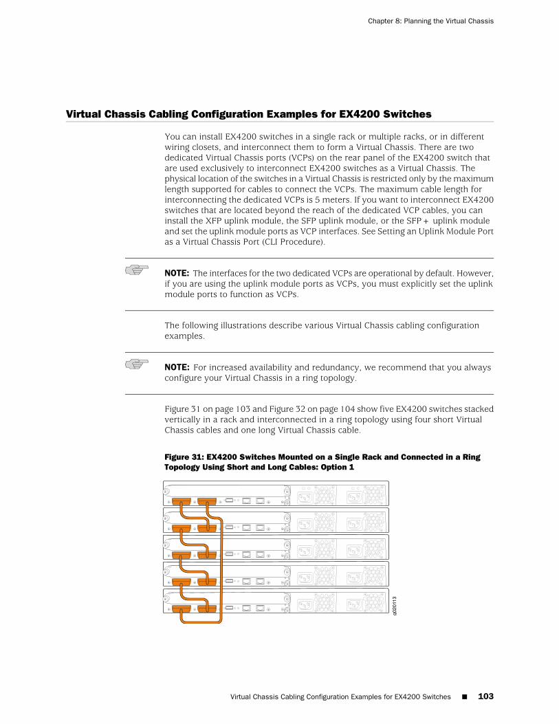
Virtual Chassis Cabling Configuration Examples for EX4200 Switches
You can install EX4200 switches in a single rack or multiple racks, or in differentwiring closets, and interconnect them to form a Virtual Chassis. There are twodedicated Virtual Chassis ports (VCPs) on the rear panel of the EX4200 switch thatare used exclusively to interconnect EX4200 switches as a Virtual Chassis. Thephysical location of the switches in a Virtual Chassis is restricted only by the maximumlength supported for cables to connect the VCPs. The maximum cable length forinterconnecting the dedicated VCPs is 5 meters. If you want to interconnect EX4200switches that are located beyond the reach of the dedicated VCP cables, you caninstall the XFP uplink module, the SFP uplink module, or the SFP+ uplink moduleand set the uplink module ports as VCP interfaces. See Setting an Uplink Module Portas a Virtual Chassis Port (CLI Procedure).
NOTE: The interfaces for the two dedicated VCPs are operational by default. However,if you are using the uplink module ports as VCPs, you must explicitly set the uplinkmodule ports to function as VCPs.
The following illustrations describe various Virtual Chassis cabling configurationexamples.
NOTE: For increased availability and redundancy, we recommend that you alwaysconfigure your Virtual Chassis in a ring topology.
Figure 31 on page 103 and Figure 32 on page 104 show five EX4200 switches stackedvertically in a rack and interconnected in a ring topology using four short VirtualChassis cables and one long Virtual Chassis cable.
Figure 31: EX4200 Switches Mounted on a Single Rack and Connected in a RingTopology Using Short and Long Cables: Option 1
Virtual Chassis Cabling Configuration Examples for EX4200 Switches ■ 103
Chapter 8: Planning the Virtual Chassis
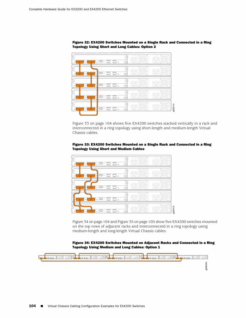
Figure 32: EX4200 Switches Mounted on a Single Rack and Connected in a RingTopology Using Short and Long Cables: Option 2
Figure 33 on page 104 shows five EX4200 switches stacked vertically in a rack andinterconnected in a ring topology using short-length and medium-length VirtualChassis cables.
Figure 33: EX4200 Switches Mounted on a Single Rack and Connected in a RingTopology Using Short and Medium Cables
Figure 34 on page 104 and Figure 35 on page 105 show five EX4200 switches mountedon the top rows of adjacent racks and interconnected in a ring topology usingmedium-length and long-length Virtual Chassis cables.
Figure 34: EX4200 Switches Mounted on Adjacent Racks and Connected in a RingTopology Using Medium and Long Cables: Option 1
104 ■ Virtual Chassis Cabling Configuration Examples for EX4200 Switches
Complete Hardware Guide for EX3200 and EX4200 Ethernet Switches
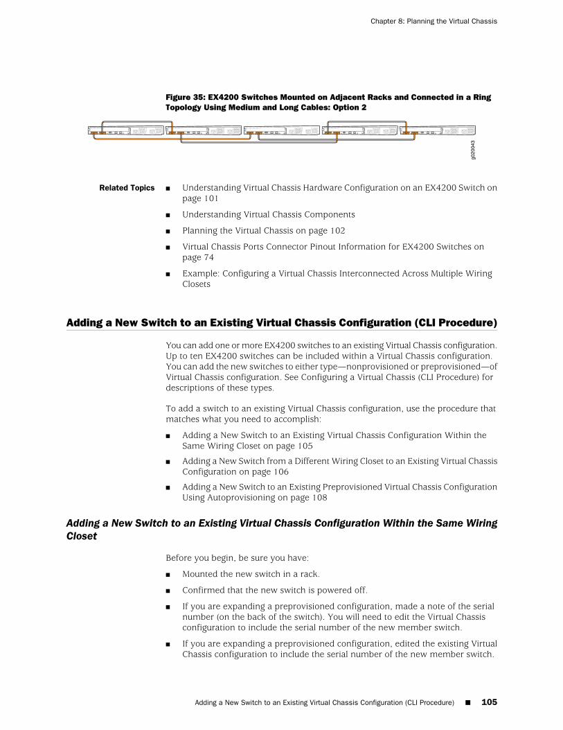
Figure 35: EX4200 Switches Mounted on Adjacent Racks and Connected in a RingTopology Using Medium and Long Cables: Option 2
Related Topics ■ Understanding Virtual Chassis Hardware Configuration on an EX4200 Switch onpage 101
■ Understanding Virtual Chassis Components
■ Planning the Virtual Chassis on page 102
■ Virtual Chassis Ports Connector Pinout Information for EX4200 Switches onpage 74
■ Example: Configuring a Virtual Chassis Interconnected Across Multiple WiringClosets
Adding a New Switch to an Existing Virtual Chassis Configuration (CLI Procedure)
You can add one or more EX4200 switches to an existing Virtual Chassis configuration.Up to ten EX4200 switches can be included within a Virtual Chassis configuration.You can add the new switches to either type—nonprovisioned or preprovisioned—ofVirtual Chassis configuration. See Configuring a Virtual Chassis (CLI Procedure) fordescriptions of these types.
To add a switch to an existing Virtual Chassis configuration, use the procedure thatmatches what you need to accomplish:
■ Adding a New Switch to an Existing Virtual Chassis Configuration Within theSame Wiring Closet on page 105
■ Adding a New Switch from a Different Wiring Closet to an Existing Virtual ChassisConfiguration on page 106
■ Adding a New Switch to an Existing Preprovisioned Virtual Chassis ConfigurationUsing Autoprovisioning on page 108
Adding a New Switch to an Existing Virtual Chassis Configuration Within the Same WiringCloset
Before you begin, be sure you have:
■ Mounted the new switch in a rack.
■ Confirmed that the new switch is powered off.
■ If you are expanding a preprovisioned configuration, made a note of the serialnumber (on the back of the switch). You will need to edit the Virtual Chassisconfiguration to include the serial number of the new member switch.
■ If you are expanding a preprovisioned configuration, edited the existing VirtualChassis configuration to include the serial number of the new member switch.
Adding a New Switch to an Existing Virtual Chassis Configuration (CLI Procedure) ■ 105
Chapter 8: Planning the Virtual Chassis
You can specify the role of the new member switch when you add its serialnumber in the Virtual Chassis configuration file. The parameters specified in themaster Virtual Chassis configuration file are applied after the new member switchhas been interconnected to an existing member switch.
NOTE: After you have created a preprovisioned Virtual Chassis configuration, youcan use the autoprovisioning feature to add member switches to that configuration.
To add a new member switch to an existing Virtual Chassis configuration within thesame wiring closet:
1. If the new member switch has been previously configured, revert that switch’sconfiguration to the factory defaults. See Reverting to the Default FactoryConfiguration for the EX Series Switch.
2. Interconnect the unpowered new switch to at least one member of the existingVirtual Chassis configuration using the dedicated Virtual Chassis ports (VCPs).
3. Power on the new switch.
4. Confirm that the new member switch is now included within the Virtual Chassisconfiguration by checking the front-panel display for the member ID. It shoulddisplay a member ID that is higher than 0 (1 through 9), because there is alreadyat least one member of the Virtual Chassis configuration.
NOTE: If you are using a preprovisioned configuration, the member ID is automaticallyassigned to the member’s serial number in the configuration file.
Adding a New Switch from a Different Wiring Closet to an Existing Virtual ChassisConfiguration
To add a new switch from a different wiring closet to an existing Virtual Chassisconfiguration, you must use a long cable to connect the new member switch acrosswiring closets. You can use a port on an SFP, SFP+ or XFP uplink module, or an SFPnetwork port on an EX4200-24F switch, and a fiber-optic cable for this purpose.
Before you begin, be sure you have:
■ Installed the uplink modules needed for the Virtual Chassis configuration.
■ Mounted the new switch in a rack.
■ If the new member switch has been previously configured, reverted itsconfiguration to the factory defaults. See Reverting to the Default FactoryConfiguration for the EX Series Switch.
■ Powered on the new member switch as a standalone switch and configured itsuplink module ports as VCPs. Otherwise, it cannot be recognized as a memberswitch by the master.
106 ■ Adding a New Switch from a Different Wiring Closet to an Existing Virtual Chassis Configuration
Complete Hardware Guide for EX3200 and EX4200 Ethernet Switches
■ If you are expanding a preprovisioned configuration, made a note of the serialnumber (on the back of the switch). You will need to edit the Virtual Chassisconfiguration to include the serial number of the new member switch.
■ If you are expanding a preprovisioned configuration, edited the existing VirtualChassis configuration to include the serial number of the new member switch.You can specify the role of the new member switch when you add its serialnumber in the Virtual Chassis configuration file. The parameters specified in themaster Virtual Chassis configuration file are applied after the new member switchhas been interconnected with its uplink VCP to an existing member switch.
■ Confirmed that the new, currently standalone switch is powered off.
■ Prepared an existing member switch for interconnecting with the new switchthrough an uplink module port by configuring an uplink module port as a VCPon the existing member switch.
NOTE: After you have created a preprovisioned Virtual Chassis configuration, youcan use the autoprovisioning feature to add member switches to that configuration.
To add a new member switch that is going to be interconnected with the existingVirtual Chassis configuration across wiring closets:
1. Power on the new switch.
2. Connect a laptop or terminal to the console port of the switch, or use EZSetupon the standalone switch to specify temporary identification parameters. (Whenyou interconnect the new member switch with the existing Virtual Chassisconfiguration, the master will overwrite and disable any specified parametersthat conflict with the Virtual Chassis parameters or assigned memberconfiguration.)
3. Use the CLI or the J-Web interface to set the uplink module ports as VCPs.
NOTE: If you are using a nonprovisioned configuration, you might configure the newmember switch with a mastership priority value that is less than that of the existingmember switches. Doing so ensures that the new member switch will function in alinecard role when it is included within the Virtual Chassis configuration.
4. Power off the new switch.
5. Interconnect the new member switch to at least one member of the existingVirtual Chassis configuration using the uplink module ports on each of theswitches that have been configured as VCPs.
6. Power on the new member switch.
7. Confirm that the new member switch is now included within the Virtual Chassisconfiguration by checking the front-panel display for the member ID. It shoulddisplay a member ID that is higher than 0 (1 through 9), because there is alreadyat least one member of the Virtual Chassis configuration.
Adding a New Switch from a Different Wiring Closet to an Existing Virtual Chassis Configuration ■ 107
Chapter 8: Planning the Virtual Chassis
NOTE: If you are using a preprovisioned configuration, the member ID is automaticallyassigned to the member's serial number in the configuration file.
Adding a New Switch to an Existing Preprovisioned Virtual Chassis Configuration UsingAutoprovisioning
Before you begin, be sure you have:
■ Installed the uplink modules needed for the Virtual Chassis configuration.
■ Mounted the new switch in a rack.
■ Ensured that the preprovisioned Virtual Chassis configuration has an activemaster. For more information, see Example: Configuring a Virtual Chassis Usinga Preprovisioned Configuration File.
■ On the master, configured the Link Level Discovery Protocol (LLDP) on the uplinkmodule ports that will be used as VCPs. LLDP is configured by default but mighthave been disabled. To configure LLDP, see Configuring LLDP (CLI Procedure)or Configuring LLDP (J-Web Procedure).
■ Ensured that the new member switch has the factory-default configuration. Ifthe new member switch has been previously configured, revert its configurationto the factory defaults. See Reverting to the Default Factory Configuration forthe EX Series Switch.
■ Made a note of the serial number (on the back of the switch). You will need toedit the Virtual Chassis configuration to include the serial number of the newmember switch.
■ Edited the existing Virtual Chassis preprovisioned configuration to include theserial number of the new member switch. You can specify the role of the newmember switch when you add its serial number to the Virtual Chassisconfiguration file. The parameters specified in the master Virtual Chassisconfiguration file are applied to the new member switch after it has beeninterconnected through its uplink VCP to an existing member switch.
■ Prepared an existing member switch to interconnect with the new switch throughan uplink module port by configuring an uplink module port as a VCP on theexisting member switch.
■ Ensured that the operational modes of the uplink modules on the existing memberswitch and the new member switch match.
■ Confirmed that the new member switch is powered off.
■ Interconnected the existing switch with the new switch using the appropriatecable.
If these conditions are not met, autoprovisioning will not work and you will need tomanually configure uplink module ports on the switch to be added to the configurationto be VCPs. For more information, see Setting an Uplink Module Port as a VirtualChassis Port (CLI Procedure).
108 ■ Adding a New Switch to an Existing Preprovisioned Virtual Chassis Configuration Using Autoprovisioning
Complete Hardware Guide for EX3200 and EX4200 Ethernet Switches

To add a switch to an existing preprovisioned Virtual Chassis configuration using theautoprovisioning feature:
1. Power on the new member switch.
2. Confirm that the new member switch is now included in the Virtual Chassisconfiguration by checking the front-panel display for the member ID. It shoulddisplay a member ID in the range from 0 through 9 because there was alreadyat least one member of the Virtual Chassis configuration. The member ID isautomatically assigned to the new member switch's serial number in theconfiguration file.
Related Topics ■ Example: Expanding a Virtual Chassis Configuration in a Single Wiring Closet
■ Example: Setting Up a Multimember Virtual Chassis Access Switch with a DefaultConfiguration
■ Example: Configuring a Virtual Chassis Interconnected Across Multiple WiringClosets
■ Example: Configuring a Virtual Chassis Using a Preprovisioned ConfigurationFile
■ Example: Configuring Automatic Software Update on Virtual Chassis MemberSwitches
■ Monitoring Virtual Chassis Configuration Status and Statistics
■ Replacing a Member Switch of a Virtual Chassis Configuration (CLI Procedure)on page 182
■ Reverting to the Default Factory Configuration for the EX Series Switch
Adding a New Switch to an Existing Preprovisioned Virtual Chassis Configuration Using Autoprovisioning ■ 109
Chapter 8: Planning the Virtual Chassis

110 ■ Adding a New Switch to an Existing Preprovisioned Virtual Chassis Configuration Using Autoprovisioning
Complete Hardware Guide for EX3200 and EX4200 Ethernet Switches

Part 3
Installing and Connecting the Switch andSwitch Components
■ Installing the Switch on page 113
■ Installing Switch Components on page 129
■ Connecting the Switch on page 141
■ Performing Initial Configuration on page 161
Installing and Connecting the Switch and Switch Components ■ 111

112 ■ Installing and Connecting the Switch and Switch Components
Complete Hardware Guide for EX3200 and EX4200 Ethernet Switches

Chapter 9
Installing the Switch
■ Installing and Connecting an EX3200 or EX4200 Switch on page 113
■ Unpacking an EX3200 or EX4200 Switch on page 114
■ Mounting an EX3200 or EX4200 Switch on page 116
■ Mounting an EX3200 or EX4200 Switch on a Desk or Other LevelSurface on page 117
■ Mounting an EX3200 or EX4200 Switch on Two Posts in a Rack orCabinet on page 118
■ Mounting an EX3200 or EX4200 Switch on Four Posts in a Rack orCabinet on page 121
■ Mounting an EX3200 or EX4200 Switch in a Recessed Position in a Rack orCabinet on page 124
■ Mounting an EX3200 or EX4200 Switch on a Wall on page 125
Installing and Connecting an EX3200 or EX4200 Switch
The EX3200 and EX4200 switch chassis is a rigid sheet-metal structure that housesthe hardware components.
To install and connect an EX3200 or EX4200 switch:
1. Follow instructions in “Unpacking an EX3200 or EX4200 Switch” on page 114.
2. Mount the switch by following instructions appropriate for your site:
■ “Mounting an EX3200 or EX4200 Switch on Two Posts in a Rack or Cabinet”on page 118 (using the mounting brackets provided)
■ “Mounting an EX3200 or EX4200 Switch on Four Posts in a Rack or Cabinet”on page 121 (using the separately orderable four-post rack-mount kit)
■ “Mounting an EX3200 or EX4200 Switch in a Recessed Position in a Rackor Cabinet” on page 124 (using the 2-in.-recess front brackets from theseparately orderable four-post rack-mount kit)
■ “Mounting an EX3200 or EX4200 Switch on a Desk or Other Level Surface”on page 117 (using the rubber feet provided)
■ “Mounting an EX3200 or EX4200 Switch on a Wall” on page 125 (using theseparately orderable wall-mount kit)
Installing and Connecting an EX3200 or EX4200 Switch ■ 113
3. Follow instructions in “Connecting Earth Ground to an EX Series Switch” onpage 141.
4. Follow instructions for connecting power as appropriate for your site:
■ Connecting AC Power to an EX3200 or EX4200 Switch on page 146
■ Connecting DC Power to an EX3200 or EX4200 Switch on page 148
5. Perform initial configuration of the switch by following instructions in “Connectingand Configuring an EX Series Switch (CLI Procedure)” on page 161 or “Connectingand Configuring an EX Series Switch (J-Web Procedure)” on page 163.
6. Set the switch’s management options by following the appropriate instructions:
■ Connecting an EX Series Switch to a Network for Out-of-Band Managementon page 152
■ Connecting an EX Series Switch to a Management Console on page 153
Related Topics Rack Requirements for EX3200 and EX4200 Switches on page 87■
■ Cabinet Requirements for EX3200 and EX4200 Switches on page 89
■ Clearance Requirements for Airflow and Hardware Maintenance for EX3200 andEX4200 Switches on page 91
Unpacking an EX3200 or EX4200 Switch
The EX3200 and EX4200 switch chassis is a rigid sheet-metal structure that housesthe hardware components. EX3200 and EX4200 switches are shipped in a cardboardcarton, secured with foam packing material. The carton also contains an accessorybox and quick start instructions.
CAUTION: EX3200 and EX4200 switches are maximally protected inside the shippingcarton. Do not unpack the switches until you are ready to begin installation.
To unpack an EX3200 or EX4200 switch (see Figure 36 on page 115):
1. Move the shipping carton to a staging area as close to the installation site aspossible, but where you have enough room to remove the system components.
2. Position the carton so that the arrows are pointing up.
3. Open the top flaps on the shipping carton.
4. Remove the accessory box and verify the contents against the parts inventoryon the label attached to the carton.
5. Pull out the packing material holding the switch in place.
114 ■ Unpacking an EX3200 or EX4200 Switch
Complete Hardware Guide for EX3200 and EX4200 Ethernet Switches
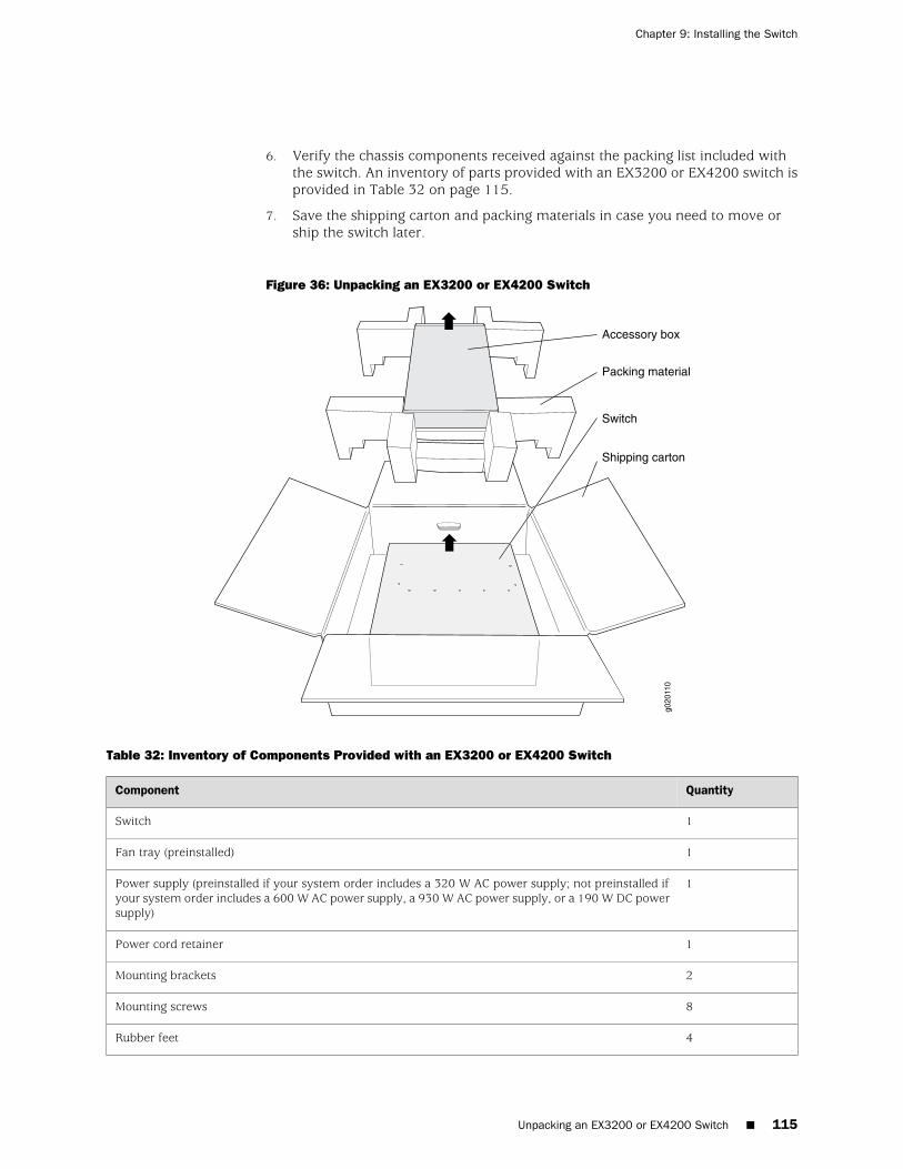
6. Verify the chassis components received against the packing list included withthe switch. An inventory of parts provided with an EX3200 or EX4200 switch isprovided in Table 32 on page 115.
7. Save the shipping carton and packing materials in case you need to move orship the switch later.
Figure 36: Unpacking an EX3200 or EX4200 Switch
Table 32: Inventory of Components Provided with an EX3200 or EX4200 Switch
QuantityComponent
1Switch
1Fan tray (preinstalled)
1Power supply (preinstalled if your system order includes a 320 W AC power supply; not preinstalled ifyour system order includes a 600 W AC power supply, a 930 W AC power supply, or a 190 W DC powersupply)
1Power cord retainer
2Mounting brackets
8Mounting screws
4Rubber feet
Unpacking an EX3200 or EX4200 Switch ■ 115
Chapter 9: Installing the Switch
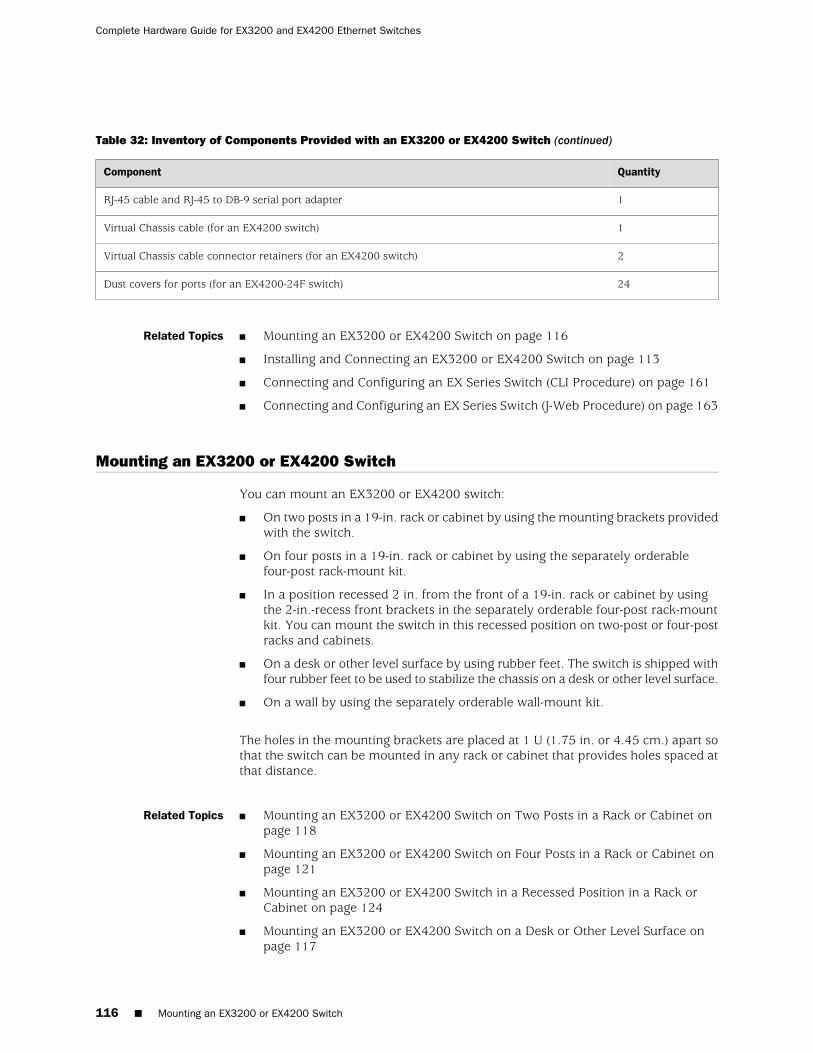
Table 32: Inventory of Components Provided with an EX3200 or EX4200 Switch (continued)
QuantityComponent
1RJ-45 cable and RJ-45 to DB-9 serial port adapter
1Virtual Chassis cable (for an EX4200 switch)
2Virtual Chassis cable connector retainers (for an EX4200 switch)
24Dust covers for ports (for an EX4200-24F switch)
Related Topics ■ Mounting an EX3200 or EX4200 Switch on page 116
■ Installing and Connecting an EX3200 or EX4200 Switch on page 113
■ Connecting and Configuring an EX Series Switch (CLI Procedure) on page 161
■ Connecting and Configuring an EX Series Switch (J-Web Procedure) on page 163
Mounting an EX3200 or EX4200 Switch
You can mount an EX3200 or EX4200 switch:
■ On two posts in a 19-in. rack or cabinet by using the mounting brackets providedwith the switch.
■ On four posts in a 19-in. rack or cabinet by using the separately orderablefour-post rack-mount kit.
■ In a position recessed 2 in. from the front of a 19-in. rack or cabinet by usingthe 2-in.-recess front brackets in the separately orderable four-post rack-mountkit. You can mount the switch in this recessed position on two-post or four-postracks and cabinets.
■ On a desk or other level surface by using rubber feet. The switch is shipped withfour rubber feet to be used to stabilize the chassis on a desk or other level surface.
■ On a wall by using the separately orderable wall-mount kit.
The holes in the mounting brackets are placed at 1 U (1.75 in. or 4.45 cm.) apart sothat the switch can be mounted in any rack or cabinet that provides holes spaced atthat distance.
Related Topics ■ Mounting an EX3200 or EX4200 Switch on Two Posts in a Rack or Cabinet onpage 118
■ Mounting an EX3200 or EX4200 Switch on Four Posts in a Rack or Cabinet onpage 121
■ Mounting an EX3200 or EX4200 Switch in a Recessed Position in a Rack orCabinet on page 124
■ Mounting an EX3200 or EX4200 Switch on a Desk or Other Level Surface onpage 117
116 ■ Mounting an EX3200 or EX4200 Switch
Complete Hardware Guide for EX3200 and EX4200 Ethernet Switches
■ Mounting an EX3200 or EX4200 Switch on a Wall on page 125
■ Connecting Earth Ground to an EX Series Switch on page 141
Mounting an EX3200 or EX4200 Switch on a Desk or Other Level Surface
You can mount an EX3200 or EX4200 switch on a desk or other level surface byusing the 4 rubber feet that are shipped with the switch. The rubber feet stabilizethe chassis.
Before mounting an EX3200 or EX4200 switch on a desk or other level surface:
■ Verify that the site meets the requirements described in “Site PreparationChecklist for EX3200 and EX4200 Switches” on page 81.
■ Place the desk in its permanent location, allowing adequate clearance for airflowand maintenance, and secure it to the building structure.
■ Read “General Safety Guidelines and Warnings for EX Series Switches” onpage 207, with particular attention to “Chassis Lifting Guidelines for EX3200 andEX4200 Switches” on page 220.
■ Remove the switch from the shipping carton (see “Unpacking an EX3200 orEX4200 Switch” on page 114).
Ensure that you have the following parts and tools available to mount the switch ona desk or other level surface:
■ Phillips (+) screwdriver, number 2
■ 4 rubber feet to stabilize the chassis on the a desk or other level surface (providedin the accessory box shipped with the switch)
■ Dust covers for ports (for EX4200-24F switches only; optional)
To mount the switch on a desk or other level surface:
1. Turn the chassis upside down on the desk or the level surface where you intendto mount the switch.
2. Attach the rubber feet to the bottom of the chassis, as shown in Figure 37 onpage 118.
3. Turn the chassis right side up on the desk or the level surface.
4. If it is an EX4200-24F switch, we recommend you insert dust covers in unusedSFP ports.
Mounting an EX3200 or EX4200 Switch on a Desk or Other Level Surface ■ 117
Chapter 9: Installing the Switch
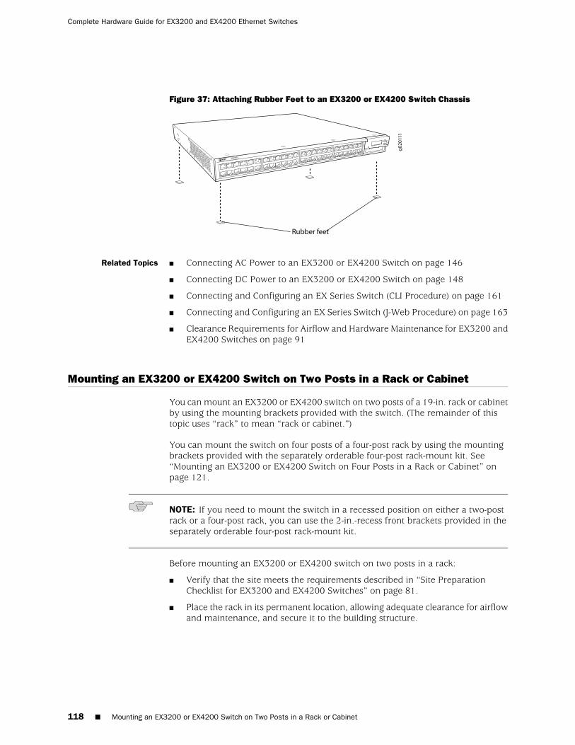
Figure 37: Attaching Rubber Feet to an EX3200 or EX4200 Switch Chassis
Related Topics ■ Connecting AC Power to an EX3200 or EX4200 Switch on page 146
■ Connecting DC Power to an EX3200 or EX4200 Switch on page 148
■ Connecting and Configuring an EX Series Switch (CLI Procedure) on page 161
■ Connecting and Configuring an EX Series Switch (J-Web Procedure) on page 163
■ Clearance Requirements for Airflow and Hardware Maintenance for EX3200 andEX4200 Switches on page 91
Mounting an EX3200 or EX4200 Switch on Two Posts in a Rack or Cabinet
You can mount an EX3200 or EX4200 switch on two posts of a 19-in. rack or cabinetby using the mounting brackets provided with the switch. (The remainder of thistopic uses “rack” to mean “rack or cabinet.”)
You can mount the switch on four posts of a four-post rack by using the mountingbrackets provided with the separately orderable four-post rack-mount kit. See“Mounting an EX3200 or EX4200 Switch on Four Posts in a Rack or Cabinet” onpage 121.
NOTE: If you need to mount the switch in a recessed position on either a two-postrack or a four-post rack, you can use the 2-in.-recess front brackets provided in theseparately orderable four-post rack-mount kit.
Before mounting an EX3200 or EX4200 switch on two posts in a rack:
■ Verify that the site meets the requirements described in “Site PreparationChecklist for EX3200 and EX4200 Switches” on page 81.
■ Place the rack in its permanent location, allowing adequate clearance for airflowand maintenance, and secure it to the building structure.
118 ■ Mounting an EX3200 or EX4200 Switch on Two Posts in a Rack or Cabinet
Complete Hardware Guide for EX3200 and EX4200 Ethernet Switches
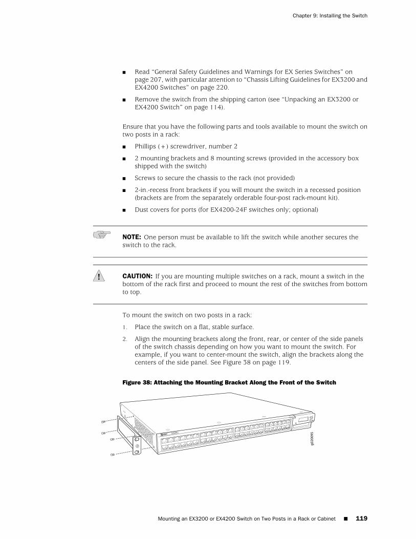
■ Read “General Safety Guidelines and Warnings for EX Series Switches” onpage 207, with particular attention to “Chassis Lifting Guidelines for EX3200 andEX4200 Switches” on page 220.
■ Remove the switch from the shipping carton (see “Unpacking an EX3200 orEX4200 Switch” on page 114).
Ensure that you have the following parts and tools available to mount the switch ontwo posts in a rack:
■ Phillips (+) screwdriver, number 2
■ 2 mounting brackets and 8 mounting screws (provided in the accessory boxshipped with the switch)
■ Screws to secure the chassis to the rack (not provided)
■ 2-in.-recess front brackets if you will mount the switch in a recessed position(brackets are from the separately orderable four-post rack-mount kit).
■ Dust covers for ports (for EX4200-24F switches only; optional)
NOTE: One person must be available to lift the switch while another secures theswitch to the rack.
CAUTION: If you are mounting multiple switches on a rack, mount a switch in thebottom of the rack first and proceed to mount the rest of the switches from bottomto top.
To mount the switch on two posts in a rack:
1. Place the switch on a flat, stable surface.
2. Align the mounting brackets along the front, rear, or center of the side panelsof the switch chassis depending on how you want to mount the switch. Forexample, if you want to center-mount the switch, align the brackets along thecenters of the side panel. See Figure 38 on page 119.
Figure 38: Attaching the Mounting Bracket Along the Front of the Switch
Mounting an EX3200 or EX4200 Switch on Two Posts in a Rack or Cabinet ■ 119
Chapter 9: Installing the Switch
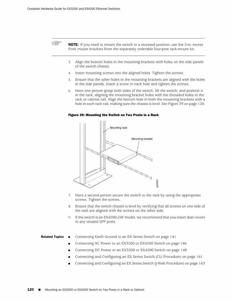
NOTE: If you need to mount the switch in a recessed position, use the 2-in.-recessfront mount brackets from the separately orderable four-post rack-mount kit.
3. Align the bottom holes in the mounting brackets with holes on the side panelsof the switch chassis.
4. Insert mounting screws into the aligned holes. Tighten the screws.
5. Ensure that the other holes in the mounting brackets are aligned with the holesin the side panels. Insert a screw in each hole and tighten the screws.
6. Have one person grasp both sides of the switch, lift the switch, and position itin the rack, aligning the mounting bracket holes with the threaded holes in therack or cabinet rail. Align the bottom hole in both the mounting brackets with ahole in each rack rail, making sure the chassis is level. See Figure 39 on page 120.
Figure 39: Mounting the Switch on Two Posts in a Rack
g020
094
Mounting rack
Mounting bracket
7. Have a second person secure the switch to the rack by using the appropriatescrews. Tighten the screws.
8. Ensure that the switch chassis is level by verifying that all screws on one side ofthe rack are aligned with the screws on the other side.
9. If the switch is an EX4200-24F model, we recommend that you insert dust coversin any unused SFP ports.
Related Topics ■ Connecting Earth Ground to an EX Series Switch on page 141
■ Connecting AC Power to an EX3200 or EX4200 Switch on page 146
■ Connecting DC Power to an EX3200 or EX4200 Switch on page 148
■ Connecting and Configuring an EX Series Switch (CLI Procedure) on page 161
■ Connecting and Configuring an EX Series Switch (J-Web Procedure) on page 163
120 ■ Mounting an EX3200 or EX4200 Switch on Two Posts in a Rack or Cabinet
Complete Hardware Guide for EX3200 and EX4200 Ethernet Switches
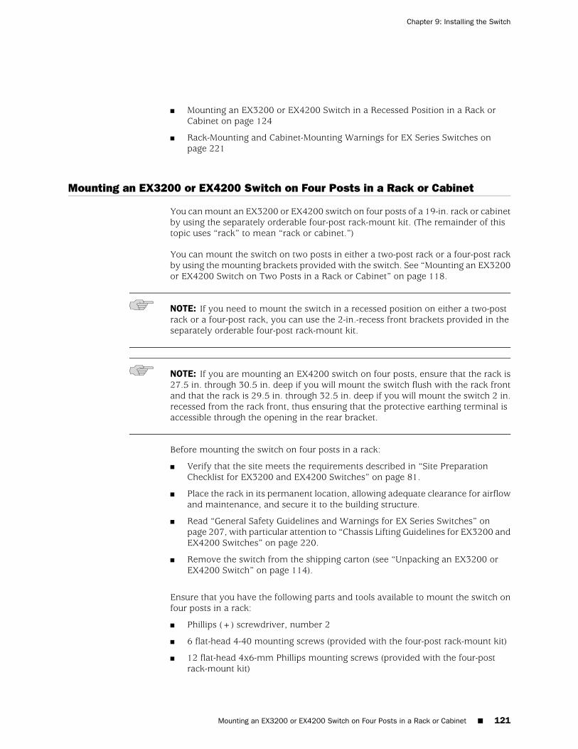
■ Mounting an EX3200 or EX4200 Switch in a Recessed Position in a Rack orCabinet on page 124
■ Rack-Mounting and Cabinet-Mounting Warnings for EX Series Switches onpage 221
Mounting an EX3200 or EX4200 Switch on Four Posts in a Rack or Cabinet
You can mount an EX3200 or EX4200 switch on four posts of a 19-in. rack or cabinetby using the separately orderable four-post rack-mount kit. (The remainder of thistopic uses “rack” to mean “rack or cabinet.”)
You can mount the switch on two posts in either a two-post rack or a four-post rackby using the mounting brackets provided with the switch. See “Mounting an EX3200or EX4200 Switch on Two Posts in a Rack or Cabinet” on page 118.
NOTE: If you need to mount the switch in a recessed position on either a two-postrack or a four-post rack, you can use the 2-in.-recess front brackets provided in theseparately orderable four-post rack-mount kit.
NOTE: If you are mounting an EX4200 switch on four posts, ensure that the rack is27.5 in. through 30.5 in. deep if you will mount the switch flush with the rack frontand that the rack is 29.5 in. through 32.5 in. deep if you will mount the switch 2 in.recessed from the rack front, thus ensuring that the protective earthing terminal isaccessible through the opening in the rear bracket.
Before mounting the switch on four posts in a rack:
■ Verify that the site meets the requirements described in “Site PreparationChecklist for EX3200 and EX4200 Switches” on page 81.
■ Place the rack in its permanent location, allowing adequate clearance for airflowand maintenance, and secure it to the building structure.
■ Read “General Safety Guidelines and Warnings for EX Series Switches” onpage 207, with particular attention to “Chassis Lifting Guidelines for EX3200 andEX4200 Switches” on page 220.
■ Remove the switch from the shipping carton (see “Unpacking an EX3200 orEX4200 Switch” on page 114).
Ensure that you have the following parts and tools available to mount the switch onfour posts in a rack:
■ Phillips (+) screwdriver, number 2
■ 6 flat-head 4-40 mounting screws (provided with the four-post rack-mount kit)
■ 12 flat-head 4x6-mm Phillips mounting screws (provided with the four-postrack-mount kit)
Mounting an EX3200 or EX4200 Switch on Four Posts in a Rack or Cabinet ■ 121
Chapter 9: Installing the Switch
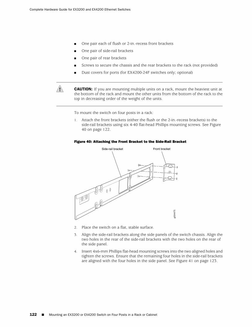
■ One pair each of flush or 2-in.-recess front brackets
■ One pair of side-rail brackets
■ One pair of rear brackets
■ Screws to secure the chassis and the rear brackets to the rack (not provided)
■ Dust covers for ports (for EX4200-24F switches only; optional)
CAUTION: If you are mounting multiple units on a rack, mount the heaviest unit atthe bottom of the rack and mount the other units from the bottom of the rack to thetop in decreasing order of the weight of the units.
To mount the switch on four posts in a rack:
1. Attach the front brackets (either the flush or the 2-in.-recess brackets) to theside-rail brackets using six 4-40 flat-head Phillips mounting screws. See Figure40 on page 122.
Figure 40: Attaching the Front Bracket to the Side-Rail Bracket
2. Place the switch on a flat, stable surface.
3. Align the side-rail brackets along the side panels of the switch chassis. Align thetwo holes in the rear of the side-rail brackets with the two holes on the rear ofthe side panel.
4. Insert 4x6-mm Phillips flat-head mounting screws into the two aligned holes andtighten the screws. Ensure that the remaining four holes in the side-rail bracketsare aligned with the four holes in the side panel. See Figure 41 on page 123.
122 ■ Mounting an EX3200 or EX4200 Switch on Four Posts in a Rack or Cabinet
Complete Hardware Guide for EX3200 and EX4200 Ethernet Switches
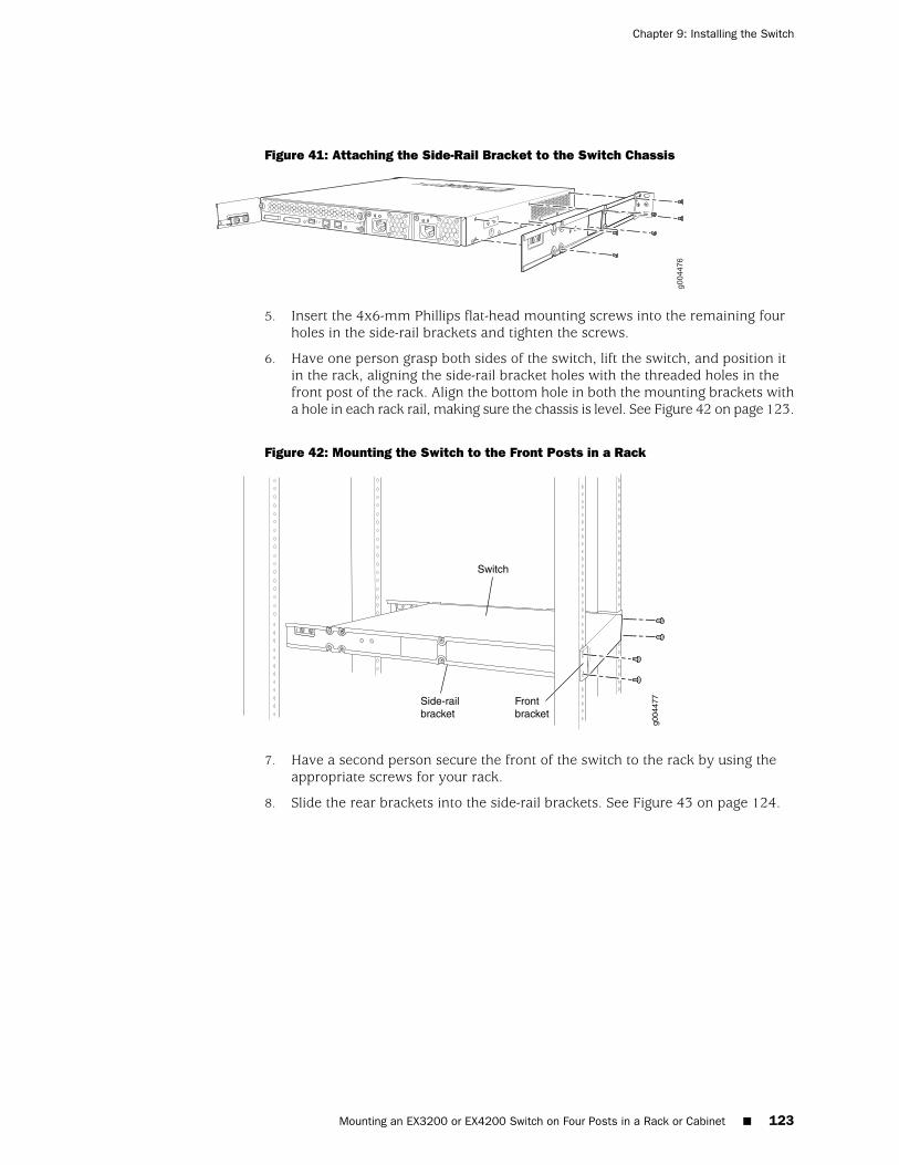
Figure 41: Attaching the Side-Rail Bracket to the Switch Chassis
5. Insert the 4x6-mm Phillips flat-head mounting screws into the remaining fourholes in the side-rail brackets and tighten the screws.
6. Have one person grasp both sides of the switch, lift the switch, and position itin the rack, aligning the side-rail bracket holes with the threaded holes in thefront post of the rack. Align the bottom hole in both the mounting brackets witha hole in each rack rail, making sure the chassis is level. See Figure 42 on page 123.
Figure 42: Mounting the Switch to the Front Posts in a Rack
g004
477Side-rail
bracket
Switch
Frontbracket
7. Have a second person secure the front of the switch to the rack by using theappropriate screws for your rack.
8. Slide the rear brackets into the side-rail brackets. See Figure 43 on page 124.
Mounting an EX3200 or EX4200 Switch on Four Posts in a Rack or Cabinet ■ 123
Chapter 9: Installing the Switch
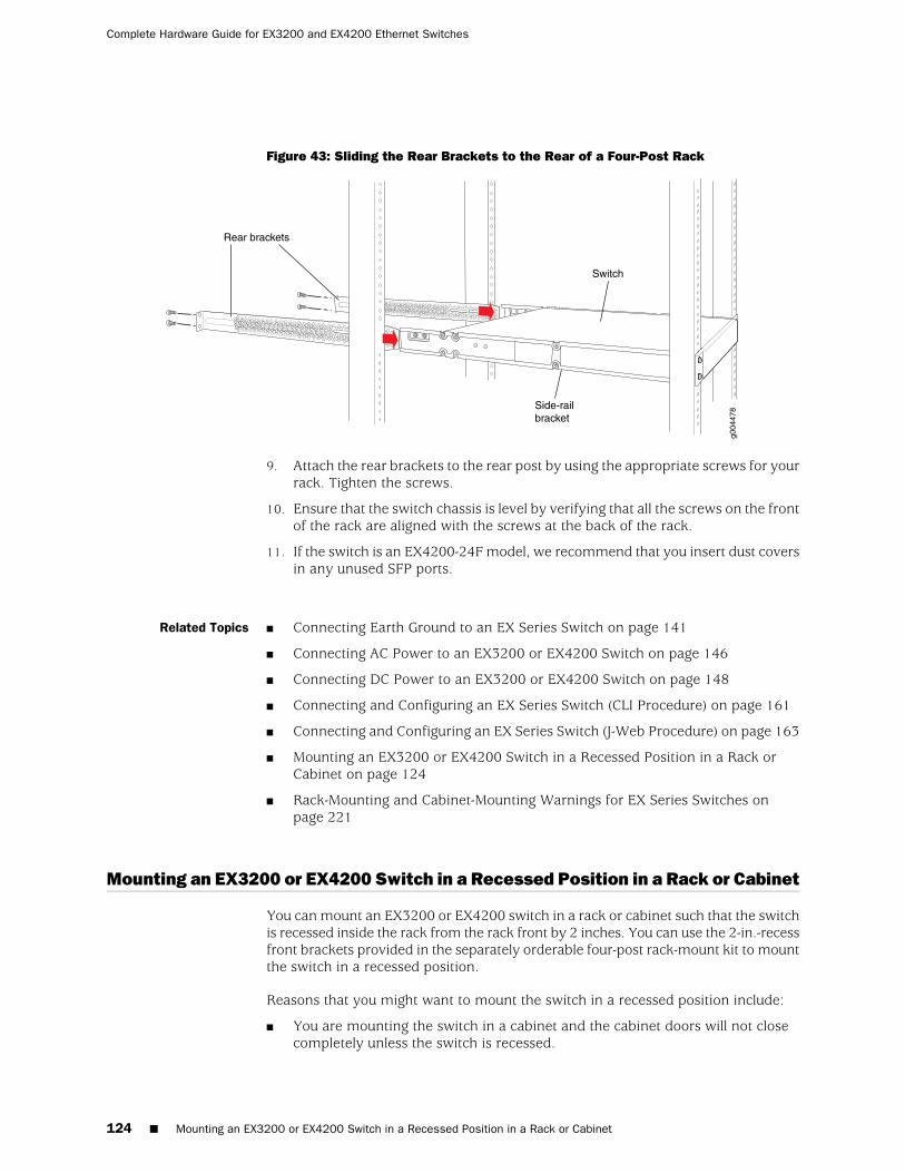
Figure 43: Sliding the Rear Brackets to the Rear of a Four-Post Rack
g004
478Side-rail
bracket
Switch
Rear brackets
9. Attach the rear brackets to the rear post by using the appropriate screws for yourrack. Tighten the screws.
10. Ensure that the switch chassis is level by verifying that all the screws on the frontof the rack are aligned with the screws at the back of the rack.
11. If the switch is an EX4200-24F model, we recommend that you insert dust coversin any unused SFP ports.
Related Topics ■ Connecting Earth Ground to an EX Series Switch on page 141
■ Connecting AC Power to an EX3200 or EX4200 Switch on page 146
■ Connecting DC Power to an EX3200 or EX4200 Switch on page 148
■ Connecting and Configuring an EX Series Switch (CLI Procedure) on page 161
■ Connecting and Configuring an EX Series Switch (J-Web Procedure) on page 163
■ Mounting an EX3200 or EX4200 Switch in a Recessed Position in a Rack orCabinet on page 124
■ Rack-Mounting and Cabinet-Mounting Warnings for EX Series Switches onpage 221
Mounting an EX3200 or EX4200 Switch in a Recessed Position in a Rack or Cabinet
You can mount an EX3200 or EX4200 switch in a rack or cabinet such that the switchis recessed inside the rack from the rack front by 2 inches. You can use the 2-in.-recessfront brackets provided in the separately orderable four-post rack-mount kit to mountthe switch in a recessed position.
Reasons that you might want to mount the switch in a recessed position include:
■ You are mounting the switch in a cabinet and the cabinet doors will not closecompletely unless the switch is recessed.
124 ■ Mounting an EX3200 or EX4200 Switch in a Recessed Position in a Rack or Cabinet
Complete Hardware Guide for EX3200 and EX4200 Ethernet Switches
■ The switch you are mounting has an uplink module with transceivers installedin it—the transceivers in the uplink module ports protrude from the front of theswitch.
To mount the switch in a recessed position on four posts, follow the instructions in“Mounting an EX3200 or EX4200 Switch on Four Posts in a Rack or Cabinet” onpage 121. To mount the switch in a recessed position on two posts, follow theinstructions in “Mounting an EX3200 or EX4200 Switch on Two Posts in a Rack orCabinet” on page 118.
Related Topics Connecting Earth Ground to an EX Series Switch on page 141■
■ Rack-Mounting and Cabinet-Mounting Warnings for EX Series Switches onpage 221
Mounting an EX3200 or EX4200 Switch on a Wall
You can mount an EX3200 or EX4200 switch on a wall by using the separatelyorderable wall-mount kit.
Before mounting an EX3200 or EX4200 switch on a wall:
■ Verify that the site meets the requirements described in “Site PreparationChecklist for EX3200 and EX4200 Switches” on page 81.
■ Read “General Safety Guidelines and Warnings for EX Series Switches” onpage 207, with particular attention to “Chassis Lifting Guidelines for EX3200 andEX4200 Switches” on page 220.
■ Remove the switch from the shipping carton (see “Unpacking an EX3200 orEX4200 Switch” on page 114).
Ensure that you have the following parts and tools available to mount the switch ona wall:
■ Phillips (+) screwdriver, number 2
■ 2 wall-mount brackets (provided with the wall-mount kit)
■ 12 wall-mount bracket screws (provided with the wall-mount kit)
■ 4 mounting screws (8-32 x 1.25 in. or M4 x 30 mm) (not included)
■ Dust covers for ports (for EX4200-24F switches only; optional)
■ Hollow wall anchors capable of supporting the combined weight of two fullyloaded switches, up to 44 lb (20 kg) (not included)—if you are mounting theswitch in sheetrock (wall board with a gypsum plaster core) or in wall board notbacked by wall studs
Mounting an EX3200 or EX4200 Switch on a Wall ■ 125
Chapter 9: Installing the Switch
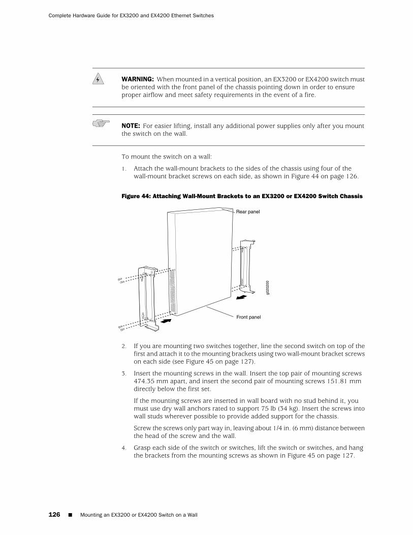
WARNING: When mounted in a vertical position, an EX3200 or EX4200 switch mustbe oriented with the front panel of the chassis pointing down in order to ensureproper airflow and meet safety requirements in the event of a fire.
NOTE: For easier lifting, install any additional power supplies only after you mountthe switch on the wall.
To mount the switch on a wall:
1. Attach the wall-mount brackets to the sides of the chassis using four of thewall-mount bracket screws on each side, as shown in Figure 44 on page 126.
Figure 44: Attaching Wall-Mount Brackets to an EX3200 or EX4200 Switch Chassis
g020
200
Front panel
Rear panel
2. If you are mounting two switches together, line the second switch on top of thefirst and attach it to the mounting brackets using two wall-mount bracket screwson each side (see Figure 45 on page 127).
3. Insert the mounting screws in the wall. Insert the top pair of mounting screws474.35 mm apart, and insert the second pair of mounting screws 151.81 mmdirectly below the first set.
If the mounting screws are inserted in wall board with no stud behind it, youmust use dry wall anchors rated to support 75 lb (34 kg). Insert the screws intowall studs wherever possible to provide added support for the chassis.
Screw the screws only part way in, leaving about 1/4 in. (6 mm) distance betweenthe head of the screw and the wall.
4. Grasp each side of the switch or switches, lift the switch or switches, and hangthe brackets from the mounting screws as shown in Figure 45 on page 127.
126 ■ Mounting an EX3200 or EX4200 Switch on a Wall
Complete Hardware Guide for EX3200 and EX4200 Ethernet Switches
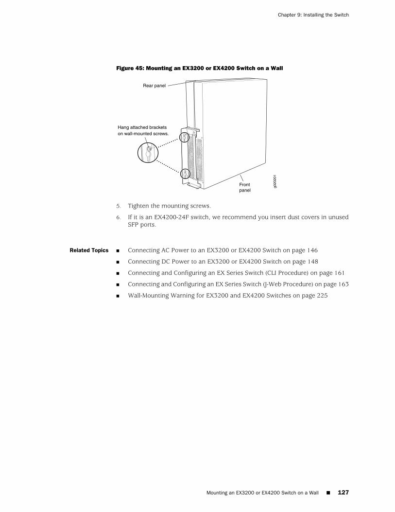
Figure 45: Mounting an EX3200 or EX4200 Switch on a Wall
Hang attached bracketson wall-mounted screws.
g020
201
Frontpanel
Rear panel
5. Tighten the mounting screws.
6. If it is an EX4200-24F switch, we recommend you insert dust covers in unusedSFP ports.
Related Topics ■ Connecting AC Power to an EX3200 or EX4200 Switch on page 146
■ Connecting DC Power to an EX3200 or EX4200 Switch on page 148
■ Connecting and Configuring an EX Series Switch (CLI Procedure) on page 161
■ Connecting and Configuring an EX Series Switch (J-Web Procedure) on page 163
■ Wall-Mounting Warning for EX3200 and EX4200 Switches on page 225
Mounting an EX3200 or EX4200 Switch on a Wall ■ 127
Chapter 9: Installing the Switch

128 ■ Mounting an EX3200 or EX4200 Switch on a Wall
Complete Hardware Guide for EX3200 and EX4200 Ethernet Switches

Chapter 10
Installing Switch Components
■ Installing and Removing EX3200 and EX4200 Switch HardwareComponents on page 129
■ Installing a Power Supply in an EX3200 or EX4200 Switch on page 130
■ Installing a Fan Tray in an EX3200 or EX4200 Switch on page 132
■ Installing an Uplink Module in an EX3200 or EX4200 Switch on page 133
■ Installing a Transceiver in an EX Series Switch on page 136
■ Connecting a Virtual Chassis Cable to an EX4200 Switch on page 137
Installing and Removing EX3200 and EX4200 Switch Hardware Components
The EX3200 and EX4200 switch chassis is a rigid sheet-metal structure that housesthe hardware components. The field-replaceable units (FRUs) in EX3200 and EX4200switches are:
■ Power supply
■ Fan tray
■ Uplink module
■ SFP transceiver
■ SFP+ transceiver
■ XFP transceiver
The power supply, fan tray, uplink module, and transceivers are hot-removable andhot-insertable: You can remove and replace them without powering off the switchor disrupting switch functions.
To install a power supply in an EX3200 or EX4200 switch, follow instructions in“Installing a Power Supply in an EX3200 or EX4200 Switch” on page 130. To removea power supply from an EX3200 or EX4200 switch, follow instructions in “Removinga Power Supply from an EX3200 or EX4200 Switch” on page 172.
To install a fan tray in an EX3200 or EX4200 switch, follow instructions in “Installinga Fan Tray in an EX3200 or EX4200 Switch” on page 132. To remove a fan tray froman EX3200 or EX4200 switch, follow instructions in “Removing a Fan Tray from anEX3200 or EX4200 Switch” on page 174.
Installing and Removing EX3200 and EX4200 Switch Hardware Components ■ 129

To install an uplink module in an EX3200 or EX4200 switch, follow instructions in“Installing an Uplink Module in an EX3200 or EX4200 Switch” on page 133. To removean uplink module from an EX3200 or EX4200 switch, follow instructions in “Removingan Uplink Module from an EX3200 or EX4200 Switch” on page 175.
To install an SFP, SFP+, or XFP transceiver in an EX3200 or EX4200 switch, followinstructions in “Installing a Transceiver in an EX Series Switch” on page 136. Toremove an SFP, SFP+, or XFP transceiver from an EX3200 or EX4200 switch, followinstructions in “Removing a Transceiver from an EX Series Switch” on page 177.
Related Topics ■ Cooling System and Airflow in an EX3200 Switch on page 31
■ Cooling System and Airflow in an EX4200 Switch on page 32
■ Power Supply in EX3200 and EX4200 Switches on page 26
■ Uplink Modules in EX3200 and EX4200 Switches on page 33
■ Optical Interface Support in EX3200 and EX4200 Switches on page 43
Installing a Power Supply in an EX3200 or EX4200 Switch
The power supply in EX3200 and EX4200 switches is a hot-removable andhot-insertable field-replaceable unit (FRU): You can remove and replace it withoutpowering off the switch or disrupting switch functions.
Ensure that you have the following parts and tools available to install a power supplyin an EX3200 or EX4200 switch chassis:
■ Electrostatic discharge (ESD) grounding strap
■ Phillips (+) screwdriver, number 2
Before you begin installing a power supply in an EX3200 or EX4200 switch, ensurethat you have taken the necessary precautions to prevent ESD damage (see“Prevention of Electrostatic Discharge Damage on EX Series Switches” on page 236).
To install a power supply in an EX3200 or EX4200 switch (see Figure 46 on page 131):
1. Attach the electrostatic discharge (ESD) grounding strap to your bare wrist, andconnect the strap to the ESD point on the chassis.
2. Taking care not to touch power supply components, pins, leads, or solderconnections, remove the power supply from its bag.
3. Loosen the locking lever screw on the left front of the power supply by using thePhillips (+) screwdriver, number 2.
4. Push down on the locking lever until it is in its lowest position.
5. Using both hands, place the power supply in the power supply slot on the rearpanel of the switch and slide it in until it is fully seated.
130 ■ Installing a Power Supply in an EX3200 or EX4200 Switch
Complete Hardware Guide for EX3200 and EX4200 Ethernet Switches
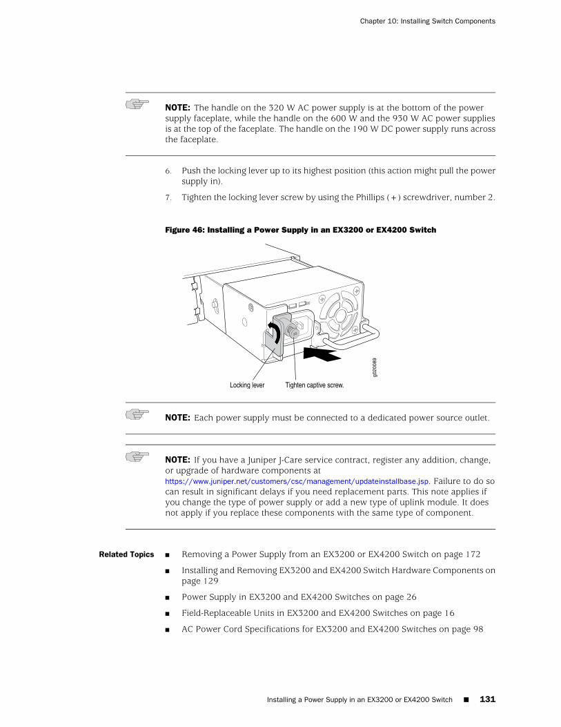
NOTE: The handle on the 320 W AC power supply is at the bottom of the powersupply faceplate, while the handle on the 600 W and the 930 W AC power suppliesis at the top of the faceplate. The handle on the 190 W DC power supply runs acrossthe faceplate.
6. Push the locking lever up to its highest position (this action might pull the powersupply in).
7. Tighten the locking lever screw by using the Phillips (+) screwdriver, number 2.
Figure 46: Installing a Power Supply in an EX3200 or EX4200 Switch
NOTE: Each power supply must be connected to a dedicated power source outlet.
NOTE: If you have a Juniper J-Care service contract, register any addition, change,or upgrade of hardware components athttps://www.juniper.net/customers/csc/management/updateinstallbase.jsp. Failure to do socan result in significant delays if you need replacement parts. This note applies ifyou change the type of power supply or add a new type of uplink module. It doesnot apply if you replace these components with the same type of component.
Related Topics ■ Removing a Power Supply from an EX3200 or EX4200 Switch on page 172
■ Installing and Removing EX3200 and EX4200 Switch Hardware Components onpage 129
■ Power Supply in EX3200 and EX4200 Switches on page 26
■ Field-Replaceable Units in EX3200 and EX4200 Switches on page 16
■ AC Power Cord Specifications for EX3200 and EX4200 Switches on page 98
Installing a Power Supply in an EX3200 or EX4200 Switch ■ 131
Chapter 10: Installing Switch Components
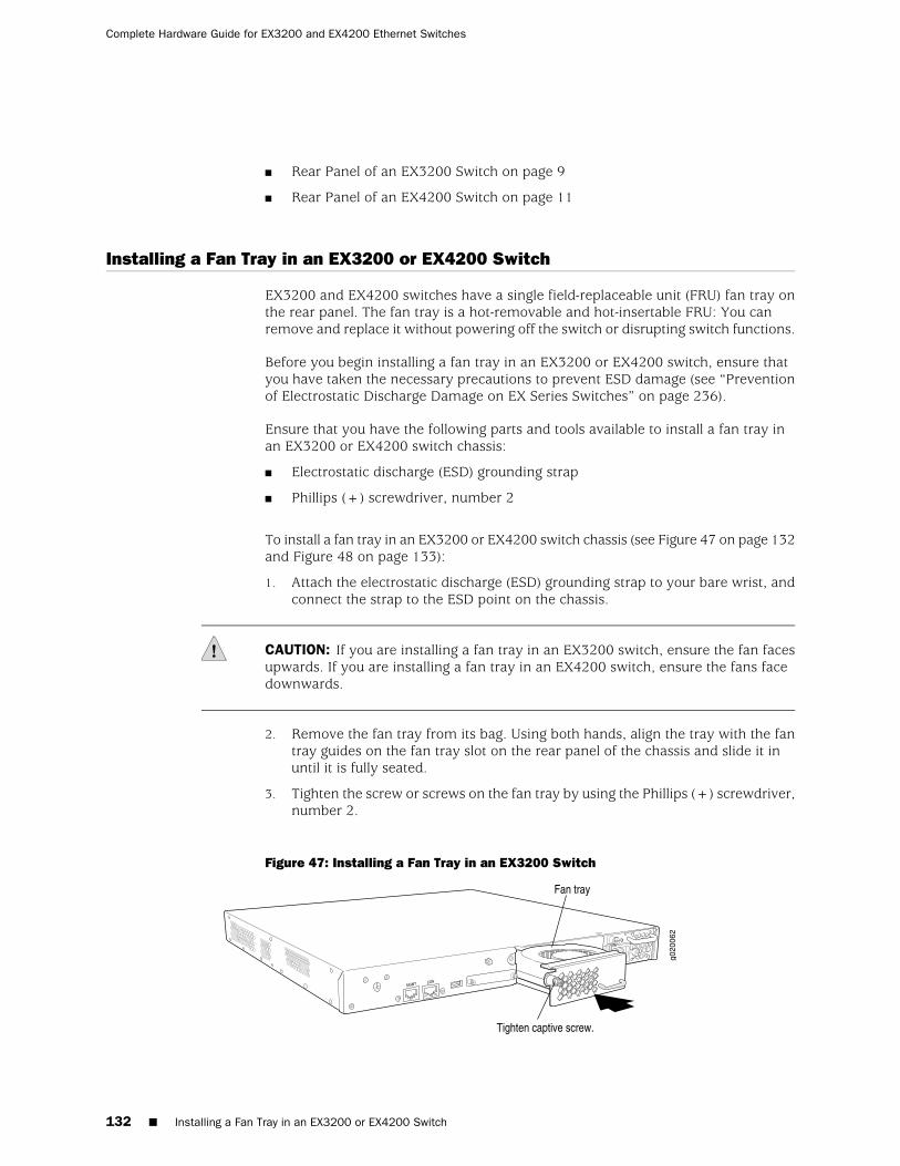
■ Rear Panel of an EX3200 Switch on page 9
■ Rear Panel of an EX4200 Switch on page 11
Installing a Fan Tray in an EX3200 or EX4200 Switch
EX3200 and EX4200 switches have a single field-replaceable unit (FRU) fan tray onthe rear panel. The fan tray is a hot-removable and hot-insertable FRU: You canremove and replace it without powering off the switch or disrupting switch functions.
Before you begin installing a fan tray in an EX3200 or EX4200 switch, ensure thatyou have taken the necessary precautions to prevent ESD damage (see “Preventionof Electrostatic Discharge Damage on EX Series Switches” on page 236).
Ensure that you have the following parts and tools available to install a fan tray inan EX3200 or EX4200 switch chassis:
■ Electrostatic discharge (ESD) grounding strap
■ Phillips (+) screwdriver, number 2
To install a fan tray in an EX3200 or EX4200 switch chassis (see Figure 47 on page 132and Figure 48 on page 133):
1. Attach the electrostatic discharge (ESD) grounding strap to your bare wrist, andconnect the strap to the ESD point on the chassis.
CAUTION: If you are installing a fan tray in an EX3200 switch, ensure the fan facesupwards. If you are installing a fan tray in an EX4200 switch, ensure the fans facedownwards.
2. Remove the fan tray from its bag. Using both hands, align the tray with the fantray guides on the fan tray slot on the rear panel of the chassis and slide it inuntil it is fully seated.
3. Tighten the screw or screws on the fan tray by using the Phillips (+) screwdriver,number 2.
Figure 47: Installing a Fan Tray in an EX3200 Switch
132 ■ Installing a Fan Tray in an EX3200 or EX4200 Switch
Complete Hardware Guide for EX3200 and EX4200 Ethernet Switches
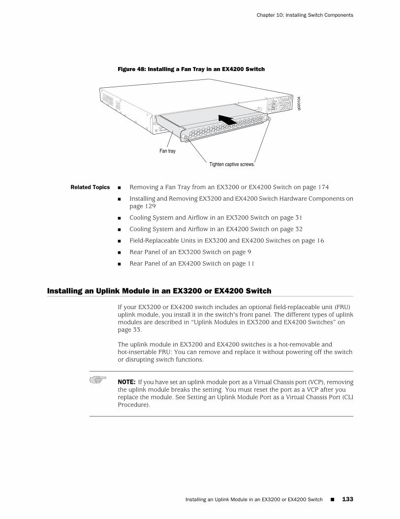
Figure 48: Installing a Fan Tray in an EX4200 Switch
Related Topics ■ Removing a Fan Tray from an EX3200 or EX4200 Switch on page 174
■ Installing and Removing EX3200 and EX4200 Switch Hardware Components onpage 129
■ Cooling System and Airflow in an EX3200 Switch on page 31
■ Cooling System and Airflow in an EX4200 Switch on page 32
■ Field-Replaceable Units in EX3200 and EX4200 Switches on page 16
■ Rear Panel of an EX3200 Switch on page 9
■ Rear Panel of an EX4200 Switch on page 11
Installing an Uplink Module in an EX3200 or EX4200 Switch
If your EX3200 or EX4200 switch includes an optional field-replaceable unit (FRU)uplink module, you install it in the switch's front panel. The different types of uplinkmodules are described in “Uplink Modules in EX3200 and EX4200 Switches” onpage 33.
The uplink module in EX3200 and EX4200 switches is a hot-removable andhot-insertable FRU: You can remove and replace it without powering off the switchor disrupting switch functions.
NOTE: If you have set an uplink module port as a Virtual Chassis port (VCP), removingthe uplink module breaks the setting. You must reset the port as a VCP after youreplace the module. See Setting an Uplink Module Port as a Virtual Chassis Port (CLIProcedure).
Installing an Uplink Module in an EX3200 or EX4200 Switch ■ 133
Chapter 10: Installing Switch Components
NOTE: On an EX3200 switch, if you install a transceiver in an SFP uplink module orin an SFP+ uplink module when the SFP+ uplink module is operating in the 1-gigabitmode, a corresponding network port from the last four built-in ports is disabled. Forexample, if you install an SFP or SFP+ transceiver in port 2 on the uplink module(ge-0/1/3), then ge-0/0/23 is disabled. The disabled port is not listed in the outputof show interface commands.
When an SFP+ uplink module is operating in 10-gigabit mode:
■ Only the 10-gigabit ports (ports 0 and 2) are enabled.
■ You can use only SFP+ transceivers in those ports.
When an SFP+ uplink module is operating in 1-gigabit mode:
■ All four ports are enabled.
■ You can use only SFP transceivers in all four ports.
Before you begin installing an uplink module in an EX3200 or EX4200 switch, ensurethat you have taken the necessary precautions to prevent ESD damage (see“Prevention of Electrostatic Discharge Damage on EX Series Switches” on page 236).
Ensure that you have the following parts and tools available to install an uplink modulein an EX3200 or EX4200 switch:
■ Electrostatic discharge (ESD) grounding strap
■ Cross-head screwdriver (provided in the uplink module kit)
To install an uplink module in an EX3200 or EX4200 switch (see Figure 49 onpage 135):
1. Attach the electrostatic discharge (ESD) grounding strap to your bare wrist, andconnect the strap to the ESD point on the chassis.
2. Loosen the screws that secure the flip-up door covering the empty uplink moduleslot on the front panel of the switch by using the cross-head screwdriver, flip thedoor upward, and remove the blanking panel covering the empty uplink moduleslot.
NOTE: If you are removing an uplink module and installing another uplink module,wait for at least 10 seconds after removing the uplink module before installing thenew or the same uplink module. If you do not wait for at least 10 seconds, theinterfaces on the uplink module might not come up.
3. Taking care not to touch module components, pins, leads, or solder connections,remove the uplink module from its bag.
134 ■ Installing an Uplink Module in an EX3200 or EX4200 Switch
Complete Hardware Guide for EX3200 and EX4200 Ethernet Switches
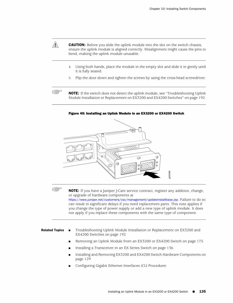
CAUTION: Before you slide the uplink module into the slot on the switch chassis,ensure the uplink module is aligned correctly. Misalignment might cause the pins tobend, making the uplink module unusable.
4. Using both hands, place the module in the empty slot and slide it in gently untilit is fully seated.
5. Flip the door down and tighten the screws by using the cross-head screwdriver.
NOTE: If the switch does not detect the uplink module, see “Troubleshooting UplinkModule Installation or Replacement on EX3200 and EX4200 Switches” on page 192.
Figure 49: Installing an Uplink Module in an EX3200 or EX4200 Switch
NOTE: If you have a Juniper J-Care service contract, register any addition, change,or upgrade of hardware components athttps://www.juniper.net/customers/csc/management/updateinstallbase.jsp. Failure to do socan result in significant delays if you need replacement parts. This note applies ifyou change the type of power supply or add a new type of uplink module. It doesnot apply if you replace these components with the same type of component.
Related Topics ■ Troubleshooting Uplink Module Installation or Replacement on EX3200 andEX4200 Switches on page 192
■ Removing an Uplink Module from an EX3200 or EX4200 Switch on page 175
■ Installing a Transceiver in an EX Series Switch on page 136
■ Installing and Removing EX3200 and EX4200 Switch Hardware Components onpage 129
■ Configuring Gigabit Ethernet Interfaces (CLI Procedure)
Installing an Uplink Module in an EX3200 or EX4200 Switch ■ 135
Chapter 10: Installing Switch Components
■ Front Panel of an EX3200 Switch on page 8
■ Front Panel of an EX4200 Switch on page 10
Installing a Transceiver in an EX Series Switch
The SFP, SFP+, and XFP transceivers for EX Series switches are hot-removable andhot-insertable field-replaceable units (FRUs): You can remove and replace themwithout powering off the switch or disrupting switch functions.
Use only optical transceivers and optical connectors purchased from Juniper Networksfor your EX Series switch.
NOTE: On an EX3200 switch, if you install a transceiver in a 1-gigabit uplink moduleport, a corresponding network port from the last four built-in ports is disabled. Forexample, if you install a transceiver in the 1-gigabit uplink module port 2 (ge-0/1/3),then built-in port 23 (ge-0/0/23) is disabled. The disabled port is not listed in theoutput of show interface commands.
Before you begin installing a transceiver in an EX Series switch, ensure that you havetaken the necessary precautions for safe handling of lasers (see “Laser and LED SafetyGuidelines and Warnings for EX Series Switches” on page 213).
Ensure that you have a rubber safety cap available to cover the transceiver.
Figure 50 on page 137 shows how to install an SFP transceiver. The procedure is thesame for all transceiver types.
To install a transceiver in an EX Series switch:
CAUTION: To avoid electrostatic discharge (ESD) damage to the transceiver, do nottouch the connector pins at the end of the transceiver.
1. Remove the transceiver from its bag.
2. Check to see whether the transceiver is covered by a rubber safety cap. If it isnot, cover the transceiver with a rubber safety cap.
WARNING: Do not leave a fiber-optic transceiver uncovered except when insertingor removing a cable. The rubber safety cap keeps the port clean and preventsaccidental exposure to laser light.
3. If the port in which you want to install the transceiver is covered with a dustcover, remove the dust cover and save it in case you need to cover the port later.If you are hot-swapping a transceiver, wait for at least 10 seconds after removingthe transceiver from the port before installing a transceiver.
136 ■ Installing a Transceiver in an EX Series Switch
Complete Hardware Guide for EX3200 and EX4200 Ethernet Switches
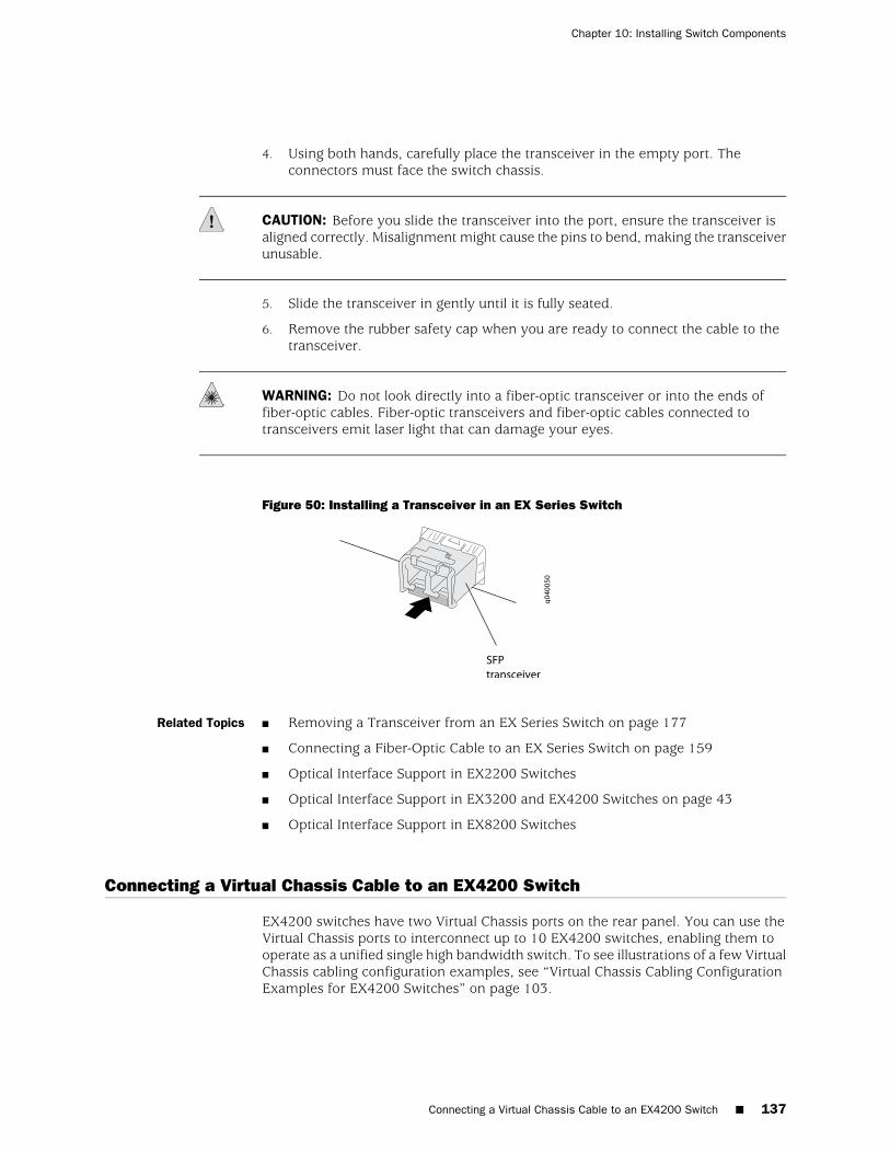
4. Using both hands, carefully place the transceiver in the empty port. Theconnectors must face the switch chassis.
CAUTION: Before you slide the transceiver into the port, ensure the transceiver isaligned correctly. Misalignment might cause the pins to bend, making the transceiverunusable.
5. Slide the transceiver in gently until it is fully seated.
6. Remove the rubber safety cap when you are ready to connect the cable to thetransceiver.
WARNING: Do not look directly into a fiber-optic transceiver or into the ends offiber-optic cables. Fiber-optic transceivers and fiber-optic cables connected totransceivers emit laser light that can damage your eyes.
Figure 50: Installing a Transceiver in an EX Series Switch
Related Topics ■ Removing a Transceiver from an EX Series Switch on page 177
■ Connecting a Fiber-Optic Cable to an EX Series Switch on page 159
■ Optical Interface Support in EX2200 Switches
■ Optical Interface Support in EX3200 and EX4200 Switches on page 43
■ Optical Interface Support in EX8200 Switches
Connecting a Virtual Chassis Cable to an EX4200 Switch
EX4200 switches have two Virtual Chassis ports on the rear panel. You can use theVirtual Chassis ports to interconnect up to 10 EX4200 switches, enabling them tooperate as a unified single high bandwidth switch. To see illustrations of a few VirtualChassis cabling configuration examples, see “Virtual Chassis Cabling ConfigurationExamples for EX4200 Switches” on page 103.
Connecting a Virtual Chassis Cable to an EX4200 Switch ■ 137
Chapter 10: Installing Switch Components
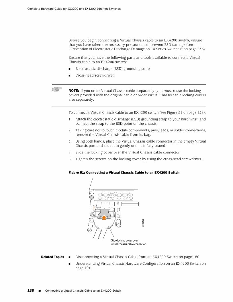
Before you begin connecting a Virtual Chassis cable to an EX4200 switch, ensurethat you have taken the necessary precautions to prevent ESD damage (see“Prevention of Electrostatic Discharge Damage on EX Series Switches” on page 236).
Ensure that you have the following parts and tools available to connect a VirtualChassis cable to an EX4200 switch:
■ Electrostatic discharge (ESD) grounding strap
■ Cross-head screwdriver
NOTE: If you order Virtual Chassis cables separately, you must reuse the lockingcovers provided with the original cable or order Virtual Chassis cable locking coversalso separately.
To connect a Virtual Chassis cable to an EX4200 switch (see Figure 51 on page 138):
1. Attach the electrostatic discharge (ESD) grounding strap to your bare wrist, andconnect the strap to the ESD point on the chassis.
2. Taking care not to touch module components, pins, leads, or solder connections,remove the Virtual Chassis cable from its bag.
3. Using both hands, place the Virtual Chassis cable connector in the empty VirtualChassis port and slide it in gently until it is fully seated.
4. Slide the locking cover over the Virtual Chassis cable connector.
5. Tighten the screws on the locking cover by using the cross-head screwdriver.
Figure 51: Connecting a Virtual Chassis Cable to an EX4200 Switch
Related Topics ■ Disconnecting a Virtual Chassis Cable from an EX4200 Switch on page 180
■ Understanding Virtual Chassis Hardware Configuration on an EX4200 Switch onpage 101
138 ■ Connecting a Virtual Chassis Cable to an EX4200 Switch
Complete Hardware Guide for EX3200 and EX4200 Ethernet Switches

■ Understanding Virtual Chassis Components
■ Planning the Virtual Chassis on page 102
■ Virtual Chassis Ports Connector Pinout Information for EX4200 Switches onpage 74
Connecting a Virtual Chassis Cable to an EX4200 Switch ■ 139
Chapter 10: Installing Switch Components

140 ■ Connecting a Virtual Chassis Cable to an EX4200 Switch
Complete Hardware Guide for EX3200 and EX4200 Ethernet Switches
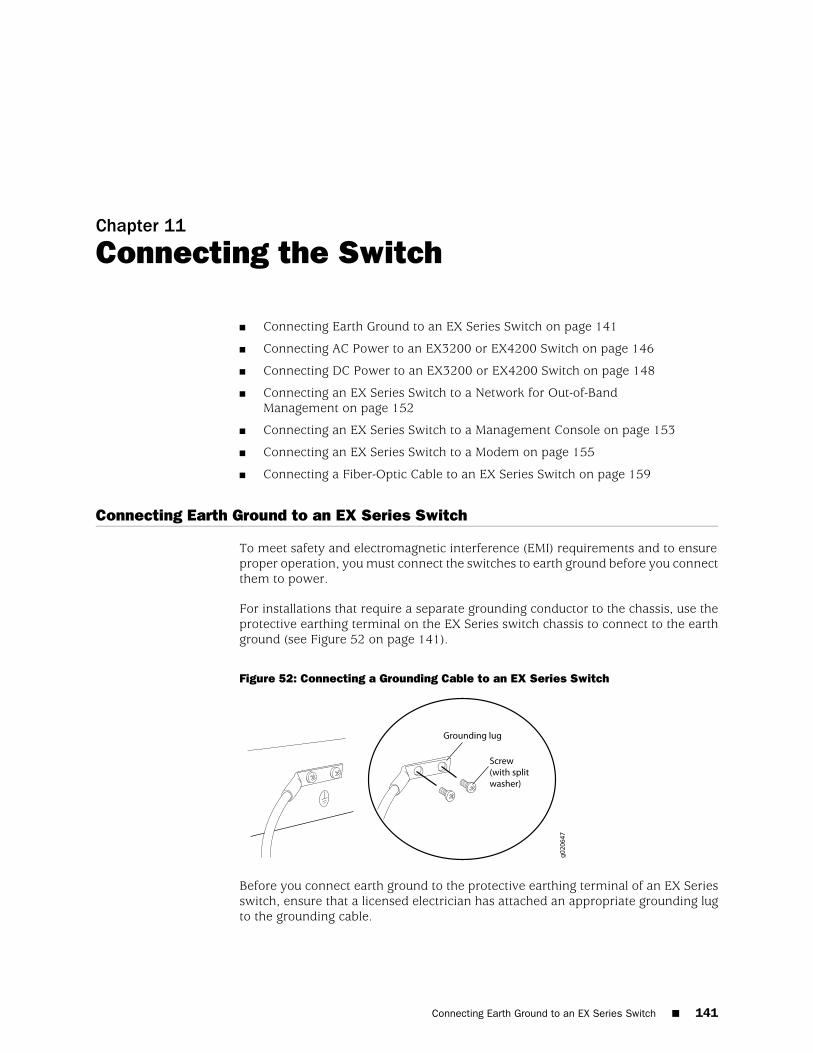
Chapter 11
Connecting the Switch
■ Connecting Earth Ground to an EX Series Switch on page 141
■ Connecting AC Power to an EX3200 or EX4200 Switch on page 146
■ Connecting DC Power to an EX3200 or EX4200 Switch on page 148
■ Connecting an EX Series Switch to a Network for Out-of-BandManagement on page 152
■ Connecting an EX Series Switch to a Management Console on page 153
■ Connecting an EX Series Switch to a Modem on page 155
■ Connecting a Fiber-Optic Cable to an EX Series Switch on page 159
Connecting Earth Ground to an EX Series Switch
To meet safety and electromagnetic interference (EMI) requirements and to ensureproper operation, you must connect the switches to earth ground before you connectthem to power.
For installations that require a separate grounding conductor to the chassis, use theprotective earthing terminal on the EX Series switch chassis to connect to the earthground (see Figure 52 on page 141).
Figure 52: Connecting a Grounding Cable to an EX Series Switch
Before you connect earth ground to the protective earthing terminal of an EX Seriesswitch, ensure that a licensed electrician has attached an appropriate grounding lugto the grounding cable.
Connecting Earth Ground to an EX Series Switch ■ 141

CAUTION: Using a grounding cable with an incorrectly attached lug can damage theswitch.
Follow the procedure that applies to your switch:
■ Connecting Earth Ground to an EX2200 or EX3200 Switch on page 142
■ Connecting Earth Ground to an EX4200 Switch on page 142
■ Connecting Earth Ground to an EX8208 Switch on page 144
■ Connecting Earth Ground to an EX8216 Switch on page 145
Connecting Earth Ground to an EX2200 or EX3200 Switch
The protective earthing terminal is located on the rear of the chassis in an EX2200switch and in an EX3200 switch.
An AC-powered EX Series switch chassis gets additional grounding when you plugthe power supply in the switch into a grounded AC power outlet by using an ACpower cord appropriate for your geographical location. For EX2200 switches, seeAC Power Cord Specifications for EX2200 Switches. For EX3200 switches, see “ACPower Cord Specifications for EX3200 and EX4200 Switches” on page 98.
Before you connect earth ground to the protective earthing terminal on an EX2200or EX3200 switch, ensure that you have the following parts and tools available:
■ Grounding cable for your switch—The grounding cable must be minimum 14 AWG(2 mm²), minimum 90°C wire, or as permitted by the local code.
■ Grounding lug for your grounding cable
■ Washers and 10-32x.25-in. screws to secure the grounding lug to the protectiveearthing terminal
■ Phillips (+) screwdriver, number 2
To connect earth ground to an EX2200 or EX3200 switch:
1. Connect one end of the grounding cable to a proper earth ground, such as therack in which the switch is mounted.
2. Place the grounding lug attached to the grounding cable over the protectiveearthing terminal. See Figure 52 on page 141.
3. Secure the grounding lug to the protective earthing terminal with screws.
4. Dress the grounding cable and ensure that it does not touch or block access toother switch components and that it does not drape where people could tripover it.
Connecting Earth Ground to an EX4200 Switch
The protective earthing terminal is located on the left side of the chassis in an EX4200switch.
142 ■ Connecting Earth Ground to an EX2200 or EX3200 Switch
Complete Hardware Guide for EX3200 and EX4200 Ethernet Switches
An AC-powered EX Series switch chassis gets additional grounding when you plugthe power supply in the switch into a grounded AC power outlet by using an ACpower cord appropriate for your geographical location. See “AC Power CordSpecifications for EX3200 and EX4200 Switches” on page 98.
Before you connect earth ground to the protective earthing terminal on an EX4200switch, ensure that you have the following parts and tools available:
■ Grounding cable for your EX4200 switch—The grounding cable must be minimum14 AWG (2 mm²), minimum 90°C wire, or as permitted by the local code.
■ Grounding lug for your grounding cable
■ Washers and 10-32x.25-in. screws to secure the grounding lug to the protectiveearthing terminal
■ Phillips (+) screwdriver, number 2
To connect earth ground to an EX4200 switch:
1. Connect one end of the grounding cable to a proper earth ground, such as therack in which the switch is mounted.
2. Place the grounding lug attached to the grounding cable over the protectiveearthing terminal. See Figure 52 on page 141.
If you mounted an EX4200 switch on four posts of a rack using the four-postrack-mount kit, the protective earthing terminal on the switch is accessiblethrough the slot on the left rear bracket. See Figure 53 on page 144.
NOTE: The protective earthing terminal on an EX4200 switch mounted on four postsis available only if the rack is 27.5 in. deep through 30.5 in. deep for a switch mountedflush with the rack front and 29.5 in. deep through 32.5 in. deep for a switch mounted2 in. recessed from the rack front.
Connecting Earth Ground to an EX4200 Switch ■ 143
Chapter 11: Connecting the Switch

Figure 53: Connecting the Grounding Lug to an EX4200 Switch on a Four-Post Rack
3. Secure the grounding lug to the protective earthing terminal with screws.
4. Dress the grounding cable and ensure that it does not touch or block access toother switch components and that it does not drape where people could tripover it.
Connecting Earth Ground to an EX8208 Switch
The protective earthing terminal is located on the left side of the chassis in an EX8208switch.
An AC-powered EX Series switch chassis gets additional grounding when you plugthe power supply in the switch into a grounded AC power outlet by using an ACpower cord appropriate for your geographical location. See AC Power CordSpecifications for an EX8200 Switch.
Before you connect earth ground to the protective earthing terminal on an EX8208switch, ensure that you have the following parts and tools available:
■ Grounding cable for your EX8208 switch—The grounding cable must be 6 AWG(13.3 mm²), minimum 60°C wire, or as permitted by the local code.
■ Grounding lug for your grounding cable. See Grounding Cable and LugSpecifications for EX8200 Switches.
■ Washers and ¼-20x.75-in. screws to secure the grounding lug to the protectiveearthing terminal
■ Phillips (+) screwdriver, number 2
To connect earth ground to an EX8208 switch:
144 ■ Connecting Earth Ground to an EX8208 Switch
Complete Hardware Guide for EX3200 and EX4200 Ethernet Switches
1. Connect one end of the grounding cable to a proper earth ground, such as therack in which the switch is mounted.
2. Place the grounding lug attached to the grounding cable over the protectiveearthing terminal. See Figure 52 on page 141.
3. Secure the grounding lug to the protective earthing terminal with screws.
4. Dress the grounding cable and ensure that it does not touch or block access toother switch components and that it does not drape where people could tripover it.
Connecting Earth Ground to an EX8216 Switch
There are two protective earthing terminals on an EX8216 switch: one on the leftside of the chassis and the other on the rear of the chassis. Only one of the twoprotective earthing terminals needs to be permanently connected to earth ground.
An AC-powered EX Series switch chassis gets additional grounding when you plugthe power supply in the switch into a grounded AC power outlet by using an ACpower cord appropriate for your geographical location. See AC Power CordSpecifications for an EX8200 Switch.
Before you connect earth ground to the protective earthing terminal on an EX8216switch, ensure that you have the following parts and tools available:
■ Grounding cable for your EX8216 switch—The grounding cable must be 2 AWG(33.6 mm²), minimum 60°C wire, or as permitted by the local code.
■ Grounding lug for your grounding cable. See Grounding Cable and LugSpecifications for EX8200 Switches.
■ Washers and ¼-20x.5/8-in. screws to secure the grounding lug to the protectiveearthing terminal
■ Phillips (+) screwdriver, number 2
To connect earth ground to an EX8216 switch:
1. Connect one end of the grounding cable to a proper earth ground, such as therack in which the switch is mounted.
2. Place the grounding lug attached to the grounding cable over the protectiveearthing terminal. See Figure 52 on page 141.
3. Secure the grounding lug to the protective earthing terminal with screws.
4. Dress the grounding cable and ensure that it does not touch or block access toother switch components and that it does not drape where people could tripover it.
Related Topics ■ Connecting AC Power to an EX2200 Switch
■ Connecting AC Power to an EX3200 or EX4200 Switch on page 146
■ Connecting DC Power to an EX3200 or EX4200 Switch on page 148
Connecting Earth Ground to an EX8216 Switch ■ 145
Chapter 11: Connecting the Switch
■ Connecting AC Power to an EX8200 Switch
■ Connecting DC Power to an EX8200 Switch
■ Connecting and Configuring an EX Series Switch (CLI Procedure) on page 161
■ Connecting and Configuring an EX Series Switch (J-Web Procedure) on page 163
■ General Safety Guidelines and Warnings for EX Series Switches on page 207
■ Grounded Equipment Warning for EX Series Switches on page 226
Connecting AC Power to an EX3200 or EX4200 Switch
The power supply in an EX3200 or EX4200 switch is a hot-removable andhot-insertable field-replaceable unit (FRU) located on the rear panel: You can removeand replace it without powering off the switch or disrupting switch functions.
Ensure that you have a power cord appropriate for your geographical location availableto connect AC power to an EX3200 or EX4200 switch.
Before you begin connecting AC power to an EX3200 or EX4200 switch:
■ Ensure that you have taken the necessary precautions to prevent ESD damage(see “Prevention of Electrostatic Discharge Damage on EX Series Switches” onpage 236).
■ Ensure that you have connected the switch chassis to earth ground.
CAUTION: Before you connect power to the switch, a licensed electrician must attacha cable lug to the grounding and power cables that you supply. A cable with anincorrectly attached lug can damage the switch (for example, by causing a shortcircuit).
To meet safety and electromagnetic interference (EMI) requirements and to ensureproper operation, you must connect EX3200 and EX4200 switches to earth groundbefore you connect them to power. For installations that require a separate groundingconductor to the chassis, use the protective earthing terminal on the switch chassisto connect to the earth ground. For instructions on connecting earth ground, see“Connecting Earth Ground to an EX Series Switch” on page 141. An EX3200 or EX4200switch gets additional grounding when you plug the power supply in the switch intoa grounded AC power outlet by using the AC power cord appropriate for yourgeographical location (see “AC Power Cord Specifications for EX3200 and EX4200Switches” on page 98).
■ Install the power supply in the chassis. For instructions on installing a powersupply in an EX3200 or EX4200 switch, see “Installing a Power Supply in anEX3200 or EX4200 Switch” on page 130.
146 ■ Connecting AC Power to an EX3200 or EX4200 Switch
Complete Hardware Guide for EX3200 and EX4200 Ethernet Switches

NOTE: Each power supply must be connected to a dedicated power source outlet.
To connect AC power to an EX3200 or EX4200 switch:
1. Ensure that the power supplies are fully inserted in the chassis and the screwson their faceplates are tightened.
2. Squeeze the two sides of the power cord retainer clip and insert the L-shapedends of the wire clip into the holes in the bracket on each side of the AC powercord inlet on the AC power supply faceplate (see Figure 54 on page 147).
3. Locate the power cord or cords shipped with the switch; the cords have plugsappropriate for your geographical location. See “AC Power Cord Specificationsfor EX3200 and EX4200 Switches” on page 98.
WARNING: Ensure that the power cord does not block access to switch componentsor drape where people can trip on it.
4. Insert the coupler end of the power cord into the AC power cord inlet on the ACpower supply faceplate.
5. Push the cord into the slot in the adjustment nut of the power cord retainer. Turnthe nut until it is tight against the base of the coupler and the slot in the nut isturned 90° from the top of the switch (see Figure 55 on page 148).
6. If the AC power source outlet has a power switch, set it to the OFF (0) position.
7. Insert the power cord plug into an AC power source outlet.
8. If the AC power source outlet has a power switch, set it to the ON (|) position.
9. Verify that the AC OK LED on the power supply is lit and is on steadily.
Figure 54: Connecting the AC Power Cord Retainer Clip to an AC Power Supply in anEX3200 or EX4200 Switch
Connecting AC Power to an EX3200 or EX4200 Switch ■ 147
Chapter 11: Connecting the Switch
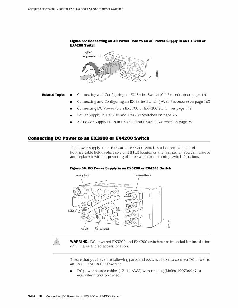
Figure 55: Connecting an AC Power Cord to an AC Power Supply in an EX3200 orEX4200 Switch
Related Topics ■ Connecting and Configuring an EX Series Switch (CLI Procedure) on page 161
■ Connecting and Configuring an EX Series Switch (J-Web Procedure) on page 163
■ Connecting DC Power to an EX3200 or EX4200 Switch on page 148
■ Power Supply in EX3200 and EX4200 Switches on page 26
■ AC Power Supply LEDs in EX3200 and EX4200 Switches on page 29
Connecting DC Power to an EX3200 or EX4200 Switch
The power supply in an EX3200 or EX4200 switch is a hot-removable andhot-insertable field-replaceable unit (FRU) located on the rear panel: You can removeand replace it without powering off the switch or disrupting switch functions.
Figure 56: DC Power Supply in an EX3200 or EX4200 Switch
WARNING: DC-powered EX3200 and EX4200 switches are intended for installationonly in a restricted access location.
Ensure that you have the following parts and tools available to connect DC power toan EX3200 or EX4200 switch:
■ DC power source cables (12–14 AWG) with ring lug (Molex 190700067 orequivalent) (not provided)
148 ■ Connecting DC Power to an EX3200 or EX4200 Switch
Complete Hardware Guide for EX3200 and EX4200 Ethernet Switches
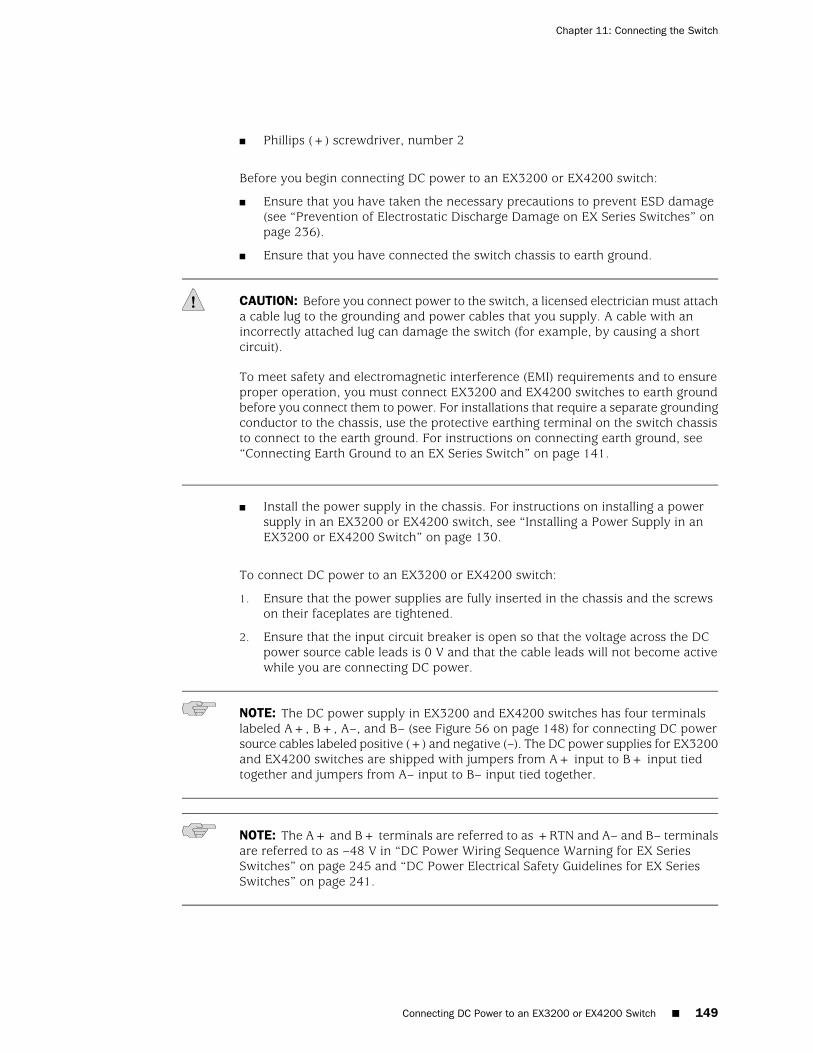
■ Phillips (+) screwdriver, number 2
Before you begin connecting DC power to an EX3200 or EX4200 switch:
■ Ensure that you have taken the necessary precautions to prevent ESD damage(see “Prevention of Electrostatic Discharge Damage on EX Series Switches” onpage 236).
■ Ensure that you have connected the switch chassis to earth ground.
CAUTION: Before you connect power to the switch, a licensed electrician must attacha cable lug to the grounding and power cables that you supply. A cable with anincorrectly attached lug can damage the switch (for example, by causing a shortcircuit).
To meet safety and electromagnetic interference (EMI) requirements and to ensureproper operation, you must connect EX3200 and EX4200 switches to earth groundbefore you connect them to power. For installations that require a separate groundingconductor to the chassis, use the protective earthing terminal on the switch chassisto connect to the earth ground. For instructions on connecting earth ground, see“Connecting Earth Ground to an EX Series Switch” on page 141.
■ Install the power supply in the chassis. For instructions on installing a powersupply in an EX3200 or EX4200 switch, see “Installing a Power Supply in anEX3200 or EX4200 Switch” on page 130.
To connect DC power to an EX3200 or EX4200 switch:
1. Ensure that the power supplies are fully inserted in the chassis and the screwson their faceplates are tightened.
2. Ensure that the input circuit breaker is open so that the voltage across the DCpower source cable leads is 0 V and that the cable leads will not become activewhile you are connecting DC power.
NOTE: The DC power supply in EX3200 and EX4200 switches has four terminalslabeled A+, B+, A–, and B– (see Figure 56 on page 148) for connecting DC powersource cables labeled positive (+) and negative (–). The DC power supplies for EX3200and EX4200 switches are shipped with jumpers from A+ input to B+ input tiedtogether and jumpers from A– input to B– input tied together.
NOTE: The A+ and B+ terminals are referred to as +RTN and A– and B– terminalsare referred to as –48 V in “DC Power Wiring Sequence Warning for EX SeriesSwitches” on page 245 and “DC Power Electrical Safety Guidelines for EX SeriesSwitches” on page 241.
Connecting DC Power to an EX3200 or EX4200 Switch ■ 149
Chapter 11: Connecting the Switch
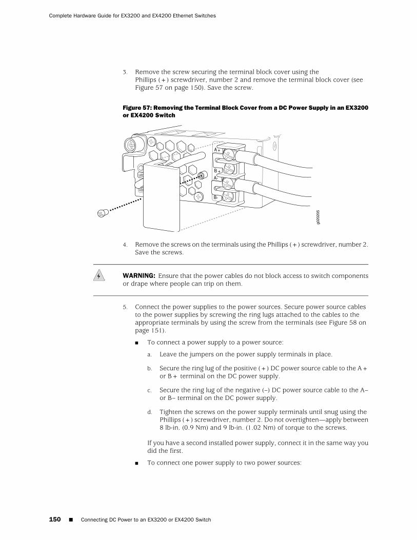
3. Remove the screw securing the terminal block cover using thePhillips (+) screwdriver, number 2 and remove the terminal block cover (seeFigure 57 on page 150). Save the screw.
Figure 57: Removing the Terminal Block Cover from a DC Power Supply in an EX3200or EX4200 Switch
4. Remove the screws on the terminals using the Phillips (+) screwdriver, number 2.Save the screws.
WARNING: Ensure that the power cables do not block access to switch componentsor drape where people can trip on them.
5. Connect the power supplies to the power sources. Secure power source cablesto the power supplies by screwing the ring lugs attached to the cables to theappropriate terminals by using the screw from the terminals (see Figure 58 onpage 151).
■ To connect a power supply to a power source:
a. Leave the jumpers on the power supply terminals in place.
b. Secure the ring lug of the positive (+) DC power source cable to the A+or B+ terminal on the DC power supply.
c. Secure the ring lug of the negative (–) DC power source cable to the A–or B– terminal on the DC power supply.
d. Tighten the screws on the power supply terminals until snug using thePhillips (+) screwdriver, number 2. Do not overtighten—apply between8 lb-in. (0.9 Nm) and 9 lb-in. (1.02 Nm) of torque to the screws.
If you have a second installed power supply, connect it in the same way youdid the first.
■ To connect one power supply to two power sources:
150 ■ Connecting DC Power to an EX3200 or EX4200 Switch
Complete Hardware Guide for EX3200 and EX4200 Ethernet Switches
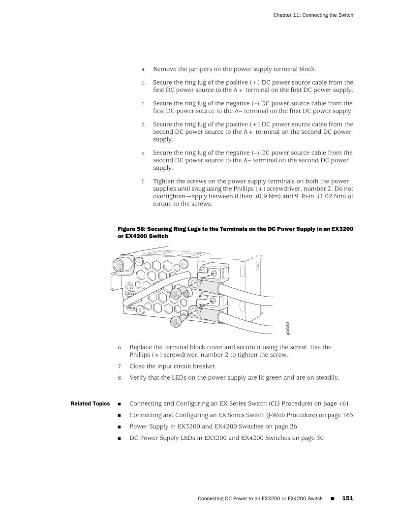
a. Remove the jumpers on the power supply terminal block.
b. Secure the ring lug of the positive (+) DC power source cable from thefirst DC power source to the A+ terminal on the first DC power supply.
c. Secure the ring lug of the negative (–) DC power source cable from thefirst DC power source to the A– terminal on the first DC power supply.
d. Secure the ring lug of the positive (+) DC power source cable from thesecond DC power source to the A+ terminal on the second DC powersupply.
e. Secure the ring lug of the negative (–) DC power source cable from thesecond DC power source to the A– terminal on the second DC powersupply.
f. Tighten the screws on the power supply terminals on both the powersupplies until snug using the Phillips (+) screwdriver, number 2. Do notovertighten—apply between 8 lb-in. (0.9 Nm) and 9 lb-in. (1.02 Nm) oftorque to the screws.
Figure 58: Securing Ring Lugs to the Terminals on the DC Power Supply in an EX3200or EX4200 Switch
6. Replace the terminal block cover and secure it using the screw. Use thePhillips (+) screwdriver, number 2 to tighten the screw.
7. Close the input circuit breaker.
8. Verify that the LEDs on the power supply are lit green and are on steadily.
Related Topics ■ Connecting and Configuring an EX Series Switch (CLI Procedure) on page 161
■ Connecting and Configuring an EX Series Switch (J-Web Procedure) on page 163
■ Power Supply in EX3200 and EX4200 Switches on page 26
■ DC Power Supply LEDs in EX3200 and EX4200 Switches on page 30
Connecting DC Power to an EX3200 or EX4200 Switch ■ 151
Chapter 11: Connecting the Switch
Connecting an EX Series Switch to a Network for Out-of-Band Management
You can monitor and manage an EX Series switch using a dedicated managementchannel. EX Series switches have a management port with an RJ-45 connector forout-of-band management. Use the management port to connect the EX Series switchto the management device.
Ensure that you have an Ethernet cable with an RJ-45 connector available. One suchcable is provided with the switch. Figure 59 on page 152 shows the RJ-45 connectorof the Ethernet cable supplied with the switch.
Figure 59: Ethernet Cable Connector
To connect an EX Series switch to a network for out-of-band management (see Figure60 on page 153):
1. Connect one end of the Ethernet cable to the management port (labeled MGMT)on the EX Series switch.
For the location of the MGMT port on different EX Series switches:
■ See Rear Panel of an EX2200 Switch.
■ See “Rear Panel of an EX3200 Switch” on page 9.
■ See “Rear Panel of an EX4200 Switch” on page 11.
■ See Switch Fabric and Routing Engine (SRE) Module in an EX8208 Switch.
■ See Routing Engine (RE) Module in an EX8216 Switch.
2. Connect the other end of the Ethernet cable to the management device.
152 ■ Connecting an EX Series Switch to a Network for Out-of-Band Management
Complete Hardware Guide for EX3200 and EX4200 Ethernet Switches
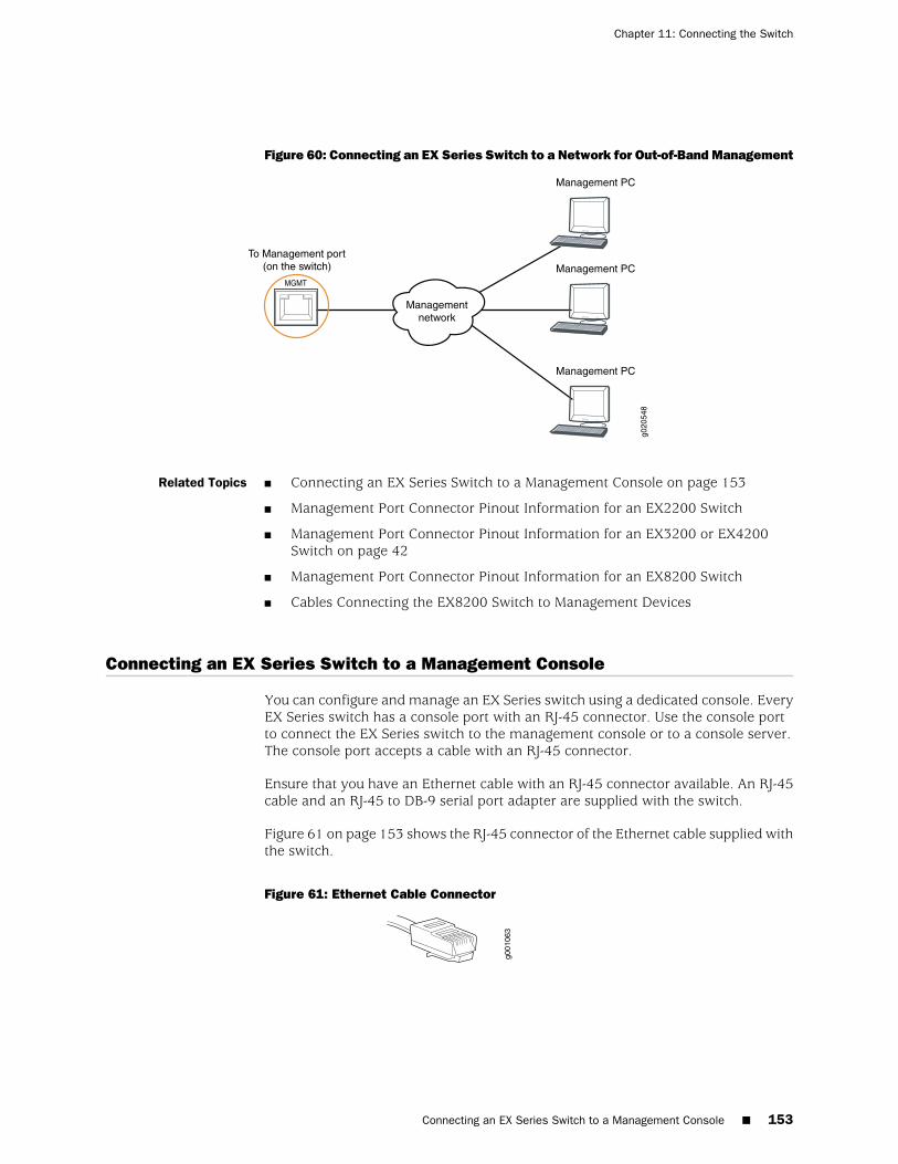
Figure 60: Connecting an EX Series Switch to a Network for Out-of-Band Management
g020
548
Management PC
Management PC
Management PC
To Management port(on the switch)
Managementnetwork
Related Topics ■ Connecting an EX Series Switch to a Management Console on page 153
■ Management Port Connector Pinout Information for an EX2200 Switch
■ Management Port Connector Pinout Information for an EX3200 or EX4200Switch on page 42
■ Management Port Connector Pinout Information for an EX8200 Switch
■ Cables Connecting the EX8200 Switch to Management Devices
Connecting an EX Series Switch to a Management Console
You can configure and manage an EX Series switch using a dedicated console. EveryEX Series switch has a console port with an RJ-45 connector. Use the console portto connect the EX Series switch to the management console or to a console server.The console port accepts a cable with an RJ-45 connector.
Ensure that you have an Ethernet cable with an RJ-45 connector available. An RJ-45cable and an RJ-45 to DB-9 serial port adapter are supplied with the switch.
Figure 61 on page 153 shows the RJ-45 connector of the Ethernet cable supplied withthe switch.
Figure 61: Ethernet Cable Connector
Connecting an EX Series Switch to a Management Console ■ 153
Chapter 11: Connecting the Switch
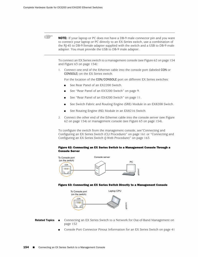
NOTE: If your laptop or PC does not have a DB-9 male connector pin and you wantto connect your laptop or PC directly to an EX Series switch, use a combination ofthe RJ-45 to DB-9 female adapter supplied with the switch and a USB to DB-9 maleadapter. You must provide the USB to DB-9 male adapter.
To connect an EX Series switch to a management console (see Figure 62 on page 154and Figure 63 on page 154):
1. Connect one end of the Ethernet cable into the console port (labeled CON orCONSOLE) on the EX Series switch.
For the location of the CON/CONSOLE port on different EX Series switches:
■ See Rear Panel of an EX2200 Switch.
■ See “Rear Panel of an EX3200 Switch” on page 9.
■ See “Rear Panel of an EX4200 Switch” on page 11.
■ See Switch Fabric and Routing Engine (SRE) Module in an EX8208 Switch.
■ See Routing Engine (RE) Module in an EX8216 Switch.
2. Connect the other end of the Ethernet cable into the console server (see Figure62 on page 154) or management console (see Figure 63 on page 154).
To configure the switch from the management console, see“Connecting andConfiguring an EX Series Switch (CLI Procedure)” on page 161 or “Connecting andConfiguring an EX Series Switch (J-Web Procedure)” on page 163.
Figure 62: Connecting an EX Series Switch to a Management Console Through aConsole Server
g020
547
Console server
PC
To Console port(on the switch)
Figure 63: Connecting an EX Series Switch Directly to a Management Console
g020
570
Laptop CPUTo Console port(on the switch)
Related Topics Connecting an EX Series Switch to a Network for Out-of-Band Management onpage 152
■
■ Console Port Connector Pinout Information for an EX Series Switch on page 41
154 ■ Connecting an EX Series Switch to a Management Console
Complete Hardware Guide for EX3200 and EX4200 Ethernet Switches
■ Cables Connecting the EX8200 Switch to Management Devices
Connecting an EX Series Switch to a Modem
You can connect an EX Series switch to a modem through the console port on theswitch.
Before you connect the port to the modem, you must set the serial console speedon the switch and configure port settings on the modem.
Before you connect the switch to a modem:
■ Perform the initial setup and configuration of the switch. See “Connecting andConfiguring an EX Series Switch (CLI Procedure)” on page 161 or “Connectingand Configuring an EX Series Switch (J-Web Procedure)” on page 163.
Ensure that you have the following parts available before you begin to connect theswitch to the modem:
■ A modem (not provided)
■ A desktop or notebook computer (not provided)
■ An RJ-45 to DB-9 adapter and an Ethernet cable (provided)
■ A phone cable (not provided)
■ If your computer does not have a DB-9 male connector pin, a USB to DB-9 maleadapter (not provided)
■ An adapter to connect the RS-232 DB-25 connector on the modem to the RJ-45to DB-9 adapter on the switch (not provided)
This topic describes:
1. Setting the Serial Console Speed for the Switch on page 155
2. Configuring the Modem on page 156
3. Connecting the Modem to the Console Port on page 157
Setting the Serial Console Speed for the Switch
Before you can connect the switch to a modem, the switch’s serial console speedmust be set to 115200 baud.
NOTE: The default serial console speed is 9600 baud.
Connecting an EX Series Switch to a Modem ■ 155
Chapter 11: Connecting the Switch
To change the serial console speed:
1. Power on the switch. (If the switch is an EX8208 or EX8216 model, see PoweringOn an EX8200 Switch.) The loader script starts.
2. You are prompted with:
Hit [Enter] to boot immediately, or space bar for command prompt.
Press the Spacebar to pause the switch in the loader state (after the JUNOSSoftware has loaded on the switch but before the software starts).
The loader> prompt appears.
3. Set the baud rate:
loader> set baudrate=115200
Press Enter.
4. Press Enter when you see the following message:
Switch baud rate to 115200 bps and press Enter.
The loader> prompt reappears.
5. Save the new serial console speed:
loader> save
Press Enter. The serial console speed is now set to 115200 baud.
6. Boot the software:
loader> boot
The boot process proceeds as normal and ends with a login prompt.
Configuring the Modem
Before you connect the modem, you must configure the modem with required portsettings.
NOTE: The following procedure uses Hayes-compatible-modem commands toconfigure the modem. If your modem is not Hayes-compatible, see the documentationfor your modem for the equivalent modem commands.
To configure the modem:
1. Connect the modem to the desktop or notebook computer.
2. Power on the modem.
156 ■ Configuring the Modem
Complete Hardware Guide for EX3200 and EX4200 Ethernet Switches
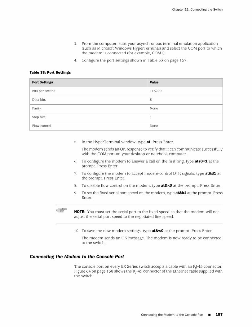
3. From the computer, start your asynchronous terminal emulation application(such as Microsoft Windows HyperTerminal) and select the COM port to whichthe modem is connected (for example, COM1).
4. Configure the port settings shown in Table 33 on page 157.
Table 33: Port Settings
ValuePort Settings
115200Bits per second
8Data bits
NoneParity
1Stop bits
NoneFlow control
5. In the HyperTerminal window, type at. Press Enter.
The modem sends an OK response to verify that it can communicate successfullywith the COM port on your desktop or notebook computer.
6. To configure the modem to answer a call on the first ring, type ats0=1 at theprompt. Press Enter.
7. To configure the modem to accept modem-control DTR signals, type at&d1 atthe prompt. Press Enter.
8. To disable flow control on the modem, type at&k0 at the prompt. Press Enter.
9. To set the fixed serial port speed on the modem, type at&b1 at the prompt. PressEnter.
NOTE: You must set the serial port to the fixed speed so that the modem will notadjust the serial port speed to the negotiated line speed.
10. To save the new modem settings, type at&w0 at the prompt. Press Enter.
The modem sends an OK message. The modem is now ready to be connectedto the switch.
Connecting the Modem to the Console Port
The console port on every EX Series switch accepts a cable with an RJ-45 connector.Figure 64 on page 158 shows the RJ-45 connector of the Ethernet cable supplied withthe switch.
Connecting the Modem to the Console Port ■ 157
Chapter 11: Connecting the Switch
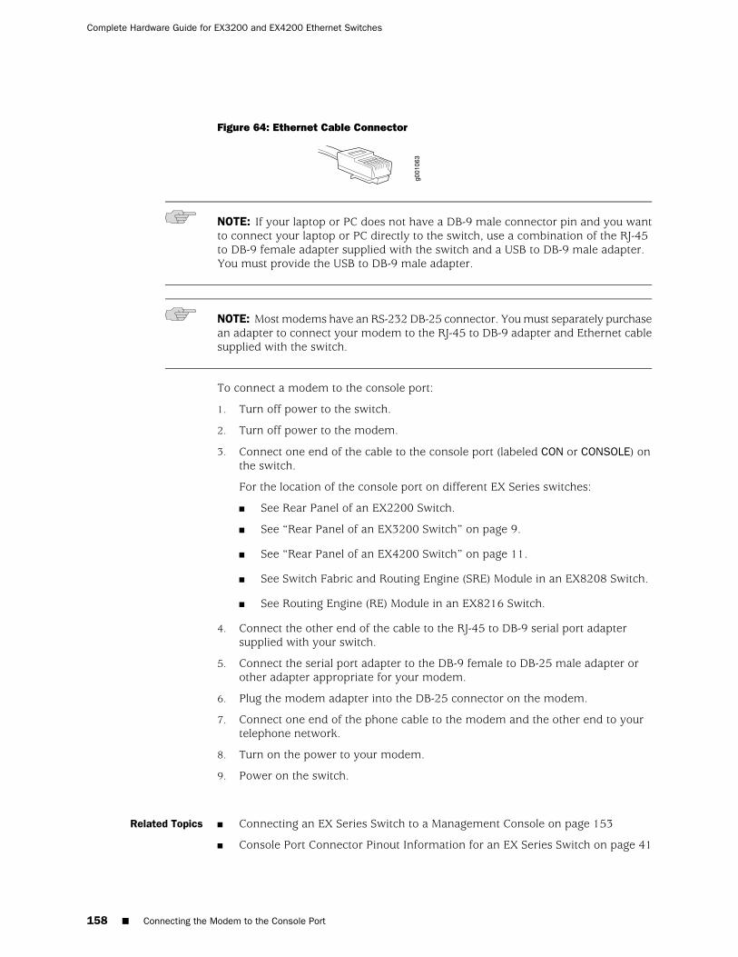
Figure 64: Ethernet Cable Connector
NOTE: If your laptop or PC does not have a DB-9 male connector pin and you wantto connect your laptop or PC directly to the switch, use a combination of the RJ-45to DB-9 female adapter supplied with the switch and a USB to DB-9 male adapter.You must provide the USB to DB-9 male adapter.
NOTE: Most modems have an RS-232 DB-25 connector. You must separately purchasean adapter to connect your modem to the RJ-45 to DB-9 adapter and Ethernet cablesupplied with the switch.
To connect a modem to the console port:
1. Turn off power to the switch.
2. Turn off power to the modem.
3. Connect one end of the cable to the console port (labeled CON or CONSOLE) onthe switch.
For the location of the console port on different EX Series switches:
■ See Rear Panel of an EX2200 Switch.
■ See “Rear Panel of an EX3200 Switch” on page 9.
■ See “Rear Panel of an EX4200 Switch” on page 11.
■ See Switch Fabric and Routing Engine (SRE) Module in an EX8208 Switch.
■ See Routing Engine (RE) Module in an EX8216 Switch.
4. Connect the other end of the cable to the RJ-45 to DB-9 serial port adaptersupplied with your switch.
5. Connect the serial port adapter to the DB-9 female to DB-25 male adapter orother adapter appropriate for your modem.
6. Plug the modem adapter into the DB-25 connector on the modem.
7. Connect one end of the phone cable to the modem and the other end to yourtelephone network.
8. Turn on the power to your modem.
9. Power on the switch.
Related Topics Connecting an EX Series Switch to a Management Console on page 153■
■ Console Port Connector Pinout Information for an EX Series Switch on page 41
158 ■ Connecting the Modem to the Console Port
Complete Hardware Guide for EX3200 and EX4200 Ethernet Switches
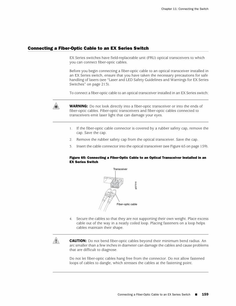
Connecting a Fiber-Optic Cable to an EX Series Switch
EX Series switches have field-replaceable unit (FRU) optical transceivers to whichyou can connect fiber-optic cables.
Before you begin connecting a fiber-optic cable to an optical transceiver installed inan EX Series switch, ensure that you have taken the necessary precautions for safehandling of lasers (see “Laser and LED Safety Guidelines and Warnings for EX SeriesSwitches” on page 213).
To connect a fiber-optic cable to an optical transceiver installed in an EX Series switch:
WARNING: Do not look directly into a fiber-optic transceiver or into the ends offiber-optic cables. Fiber-optic transceivers and fiber-optic cables connected totransceivers emit laser light that can damage your eyes.
1. If the fiber-optic cable connector is covered by a rubber safety cap, remove thecap. Save the cap.
2. Remove the rubber safety cap from the optical transceiver. Save the cap.
3. Insert the cable connector into the optical transceiver (see Figure 65 on page 159).
Figure 65: Connecting a Fiber-Optic Cable to an Optical Transceiver Installed in anEX Series Switch
g027
016
Fiber-optic cable
Transceiver
4. Secure the cables so that they are not supporting their own weight. Place excesscable out of the way in a neatly coiled loop. Placing fasteners on a loop helpscables maintain their shape.
CAUTION: Do not bend fiber-optic cables beyond their minimum bend radius. Anarc smaller than a few inches in diameter can damage the cables and cause problemsthat are difficult to diagnose.
Do not let fiber-optic cables hang free from the connector. Do not allow fastenedloops of cables to dangle, which stresses the cables at the fastening point.
Connecting a Fiber-Optic Cable to an EX Series Switch ■ 159
Chapter 11: Connecting the Switch

Related Topics ■ Disconnecting a Fiber-Optic Cable from an EX Series Switch on page 179
■ Installing a Transceiver in an EX Series Switch on page 136
■ Maintaining Fiber-Optic Cables in EX Series Switches on page 187
■ Optical Interface Support in EX2200 Switches
■ Optical Interface Support in EX3200 and EX4200 Switches on page 43
■ Optical Interface Support in EX8200 Switches
160 ■ Connecting a Fiber-Optic Cable to an EX Series Switch
Complete Hardware Guide for EX3200 and EX4200 Ethernet Switches
Chapter 12
Performing Initial Configuration
■ Connecting and Configuring an EX Series Switch (CLI Procedure) on page 161
■ Connecting and Configuring an EX Series Switch (J-Web Procedure) on page 163
■ Configuring the LCD Panel Display on EX Series Switches (CLIProcedure) on page 166
■ Setting the Mode on an SFP+ Uplink Module (CLI Procedure) on page 168
Connecting and Configuring an EX Series Switch (CLI Procedure)
There are two ways to connect and configure an EX Series switch: one method isthrough the console using the CLI and the other is using the J-Web interface. Thistopic describes the CLI procedure.
Before you begin connecting and configuring an EX Series switch through the consoleusing the CLI:
■ Set the following parameter values in the console server or PC:
■ Baud Rate—9600
■ Flow Control—None
■ Data—8
■ Parity—None
■ Stop Bits—1
■ DCD State—Disregard
■ To run the ezsetup script, the switch must have the factory default configuration.If you have configured anything on the switch and want to run ezsetup, revertto the factory default configuration. See Reverting to the Default FactoryConfiguration for the EX Series Switch.
Connecting and Configuring an EX Series Switch (CLI Procedure) ■ 161
To configure the switch from the console:
1. Connect the console port to a laptop or PC using the RJ-45 to DB-9 serial portadapter. The RJ-45 cable and RJ-45 to DB-9 serial port adapter are supplied withthe switch.
■ EX2200, EX3200, or EX4200 switch—The console port is located on therear panel of the switch.
■ EX8200 switch—The console port is located on the Switch Fabric and RoutingEngine (SRE) module in slot SRE0 in an EX8208 switch or on the RoutingEngine (RE) module in slot RE0 in an EX8216 switch.
2. At the JUNOS shell prompt root%, type ezsetup.
3. Enter the hostname. This is optional.
4. Enter the root password you plan to use for this device. You are prompted tore-enter the root password.
5. Enter yes to enable services like Telnet and SSH. By default, Telnet is not enabledand SSH is enabled.
NOTE: When Telnet is enabled, you will not be able to log in to an EX Series switchthrough Telnet using root credentials. Root login is allowed only for SSH access.
6. Use the Management Options page to select the management scenario:
NOTE: On EX8200 switches, only the out-of-band management option is available.
■ Configure in-band management. In this scenario you have the following twooptions:
■ Use the default VLAN.
■ Create a new VLAN—If you select this option, you are prompted tospecify the VLAN name, VLAN ID, management IP address, and defaultgateway. Select the ports that must be part of this VLAN.
■ Configure out-of-band management. Specify the IP address and gateway ofthe management interface. Use this IP address to connect to the switch.
7. Specify the SNMP Read Community, Location, and Contact to configure SNMPparameters. These parameters are optional.
8. Specify the system date and time. Select the time zone from the list. Theseoptions are optional.
The configured parameters are displayed. Enter yes to commit the configuration.
The configuration is committed as the active configuration for the switch. You cannow log in with the CLI or the J-Web interface to continue configuring the switch. Ifyou use the J-Web interface to continue configuring the switch, the Web session is
162 ■ Connecting and Configuring an EX Series Switch (CLI Procedure)
Complete Hardware Guide for EX3200 and EX4200 Ethernet Switches
redirected to the new management IP address. If the connection cannot be made,the J-Web interface displays instructions for starting a J-Web session.
Related Topics ■ Connecting and Configuring an EX Series Switch (J-Web Procedure) on page 163
■ Installing and Connecting an EX2200 Switch
■ Installing and Connecting an EX3200 or EX4200 Switch on page 113
■ Installing and Connecting an EX8208 Switch
■ Installing and Connecting an EX8216 Switch
Connecting and Configuring an EX Series Switch (J-Web Procedure)
There are two ways to connect and configure an EX Series switch: one method isthrough the console using the CLI and the other is using the J-Web interface. Thistopic describes the J-Web procedure.
To run the ezsetup script, the switch must have the factory default configuration. Ifyou have configured anything on the switch and want to run ezsetup, revert to thefactory default configuration. See Reverting to the Default Factory Configuration forthe EX Series Switch.
To connect and configure an EX Series switch using the J-Web interface:
1. Connect the Ethernet cable from the Ethernet port on the PC to the switch.
■ EX2200, EX3200, or EX4200 switch—Connect the cable to port 0 (ge-0/0/0)on the front panel of the switch.
■ EX8200 switch—Connect the cable to the port labeled MGMT on the SwitchFabric and Routing Engine (SRE) module in slot SRE0 in an EX8208 switchor on the Routing Engine (RE) module in slot RE0 in an EX8216 switch.
These ports are configured as the DHCP server with the default IP address,192.168.1.1. The switch can assign an IP address to the management PC in theIP address range 192.168.1.2 through 192.168.1.253.
NOTE: The switch will transition into initial setup mode only when the switch is inthe factory default configuration.
2. Transition the switch into initial setup mode:
■ EX2200 switch—Press the mode button located on the lower right cornerof the front panel for 10 seconds.
■ EX3200, EX4200, or EX8200 switch—Use the Menu and Enter buttons locatedto the right of the LCD panel (see Figure 66 on page 164):
Connecting and Configuring an EX Series Switch (J-Web Procedure) ■ 163
Chapter 12: Performing Initial Configuration
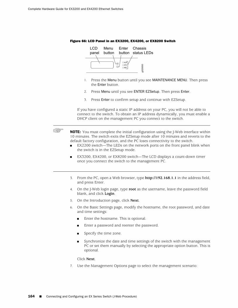
Figure 66: LCD Panel in an EX3200, EX4200, or EX8200 Switch
1. Press the Menu button until you see MAINTENANCE MENU. Then pressthe Enter button.
2. Press Menu until you see ENTER EZSetup. Then press Enter.
3. Press Enter to confirm setup and continue with EZSetup.
If you have configured a static IP address on your PC, you will not be able toconnect to the switch. To obtain an IP address dynamically, you must enable aDHCP client on the management PC you connect to the switch.
NOTE: You must complete the initial configuration using the J-Web interface within10 minutes. The switch exits the EZSetup mode after 10 minutes and reverts to thedefault factory configuration, and the PC loses connectivity to the switch.■ EX2200 switch—The LEDs on the network ports on the front panel blink when
the switch is in the EZSetup mode.
■ EX3200, EX4200, or EX8200 switch—The LCD displays a count-down timeronce you connect the switch to the management PC.
3. From the PC, open a Web browser, type http://192.168.1.1 in the address field,and press Enter.
4. On the J-Web login page, type root as the username, leave the password fieldblank, and click Login.
5. On the Introduction page, click Next.
6. On the Basic Settings page, modify the hostname, the root password, and dateand time settings:
■ Enter the hostname. This is optional.
■ Enter a password and reenter the password.
■ Specify the time zone.
■ Synchronize the date and time settings of the switch with the managementPC or set them manually by selecting the appropriate option button. This isoptional.
Click Next.
7. Use the Management Options page to select the management scenario:
164 ■ Connecting and Configuring an EX Series Switch (J-Web Procedure)
Complete Hardware Guide for EX3200 and EX4200 Ethernet Switches
NOTE: On EX8200 switches, only the out-of-band management option is available.
■ In-band Management—Use VLAN 'default' for management.
Select this option to configure all data interfaces as members of the defaultVLAN. Click Next. Specify the management IP address and the defaultgateway for the default VLAN.
■ In-band Management—Create new VLAN for management.
Select this option to create a management VLAN. Click Next. Specify theVLAN name, VLAN ID, member interfaces, management IP address, anddefault gateway for the new VLAN.
■ Out-of-band Management—Configure management port.
Select this option to configure only the management interface. Click Next.Specify the IP address and default gateway for the management interface.
8. Click Next.
9. On the Manage Access page, you may select options to enable Telnet, SSH, andSNMP services. For SNMP, you can configure the read community, location, andcontact.
10. Click Next. The Summary screen displays the configured settings.
11. Click Finish.
The configuration is committed as the active switch configuration. You can now login with the CLI or the J-Web interface to continue configuring the switch.
If you use the J-Web interface to continue configuring the switch, the Web sessionis redirected to the new management IP address. If the connection cannot be made,the J-Web interface displays instructions for starting a J-Web session.
NOTE: After the configuration takes effect, you might lose connectivity between thePC and the switch. To renew the connection, release and renew the IP address byexecuting the appropriate commands on the management PC or by removing andreinserting the Ethernet cable.
Related Topics ■ Connecting and Configuring an EX Series Switch (CLI Procedure) on page 161
■ Installing and Connecting an EX2200 Switch
■ Installing and Connecting an EX3200 or EX4200 Switch on page 113
■ Installing and Connecting an EX8208 Switch
■ Installing and Connecting an EX8216 Switch
Connecting and Configuring an EX Series Switch (J-Web Procedure) ■ 165
Chapter 12: Performing Initial Configuration
Configuring the LCD Panel Display on EX Series Switches (CLI Procedure)
The LCD panel on the front panel of EX Series switches shows two lines of text, eacha maximum of 16 characters in length. The LCD panel displays a variety ofinformation about the switch and also provides a menu to perform basic operationssuch as initial setup and reboot.
This topic describes:
1. Disabling the Maintenance Menu on page 166
2. Enabling the Maintenance Menu on page 166
3. Configuring a Custom Display Message on page 167
Disabling the Maintenance Menu
By default, the Maintenance menu in the LCD panel on an EX Series switch is enabled.Users can configure and troubleshoot the switch using the options in the Maintenancemenu.
If you do not want users to be able to configure and troubleshoot the switch usingthe options in the Maintenance menu, you can disable the menu.
To disable the Maintenance menu in the LCD panel on EX3200 or EX4200 switches:
[edit]user@switch# set chassis lcd fpc slot-number maintenance-menu disable
where slot-number is 0 on an EX3200 switch or a standalone EX4200 switch or themember ID of the member switch on a Virtual Chassis.
To disable the Maintenance menu in the LCD panel on EX8200 switches:
[edit]user@switch# set chassis lcd maintenance-menu disable
If you disable the Maintenance menu while navigating through the menu options,exit the menu to return the LCD to the idle mode.
Enabling the Maintenance Menu
By default, the Maintenance menu in the LCD panel on an EX Series switch is enabled.If you have not changed the Maintenance menu from the default setting, you do notneed to enable the menu.
To re-enable the Maintenance menu in the LCD panel on EX3200 or EX4200 switches:
[edit]user@switch# set chassis lcd fpc slot-number maintenance-menu enable
where slot-number is 0 on an EX3200 switch or a standalone EX4200 switch or themember ID of the member switch on a Virtual Chassis.
166 ■ Configuring the LCD Panel Display on EX Series Switches (CLI Procedure)
Complete Hardware Guide for EX3200 and EX4200 Ethernet Switches
To re-enable the Maintenance menu in the LCD panel on EX8200 switches:
[edit]user@switch# set chassis lcd maintenance-menu enable
Configuring a Custom Display Message
You can configure the second line of the LCD to display a custom message temporarilyfor 5 minutes or permanently.
To display a custom message temporarily:
■ On an EX3200 switch, a standalone EX4200 switch, or an EX8200 switch:
user@switch> set chassis display message message
■ On an EX4200 switch in a Virtual Chassis configuration:
user@switch> set chassis display message message fpc-slot slot-number
where slot-number is the member ID of the member switch.
To display a custom message permanently:
■ On an EX3200 switch, a standalone EX4200 switch, or an EX8200 switch:
user@switch> set chassis display message message permanent
■ On an EX4200 switch in a Virtual Chassis configuration:
user@switch> set chassis display message message fpc-slot slot-numberpermanent
where slot-number is the member ID of the member switch.
NOTE: The Menu button and the Enter button are disabled if the LCD is configuredto display a custom message.
To disable the display of the custom message:
user@switch> clear chassis display message
Related Topics LCD Panel in EX3200 and EX4200 Switches on page 13■
■ LCD Panel in an EX8200 Switch
Configuring a Custom Display Message ■ 167
Chapter 12: Performing Initial Configuration
Setting the Mode on an SFP+ Uplink Module (CLI Procedure)
SFP+ uplink modules are supported on EX3200 and EX4200 switches. You can usethese uplink modules either for two SFP+ transceivers or four SFP transceivers. Youconfigure the operating mode on the module to match the type of transceiver youwant to use—that is, for SFP+ transceivers, you configure the 10-gigabit operatingmode, and for SFP transceivers, you configure the 1-gigabit operating mode.
By default, the SFP+ uplink module operates in the 10-gigabit mode and supportsonly SFP+ transceivers. If you have not changed the module from the default settingand you want to use SFP+ transceivers, you do not need to configure the operatingmode.
To set the operating mode of an SFP+ uplink module:
1. Change the operating mode to the appropriate mode for the transceiver typeyou want to use by using one of the following commands:
[edit]user@switch# set chassis fpc 0 pic 1 sfpplus pic-mode 1g
[edit]user@switch# set chassis fpc 0 pic 1 sfpplus pic-mode 10g
2. If the switch is running:
■ JUNOS Release 10.1 or later, the changed operating mode takes effectimmediately unless a port on the SFP+ uplink module is a Virtual Chassisport (VCP). If any port on the SFP+ uplink module is a VCP, the changedoperating mode does not take effect until the next reboot of the switch.
NOTE: During the operating mode change, the Packet Forwarding Engine is restarted.In a Virtual Chassis configuration, this means that the Flexible PIC Concentratorconnection with the master is dropped and then reconnected.
■ JUNOS Release 10.0 or earlier, reboot the switch.
You can see whether the operating mode has been changed to the new mode youconfigured by issuing the show chassis pic fpc-slot slot-number pic-slot 1 command.
Related Topics ■ Uplink Modules in EX3200 and EX4200 Switches on page 33
■ Optical Interface Support in EX3200 and EX4200 Switches on page 43
168 ■ Setting the Mode on an SFP+ Uplink Module (CLI Procedure)
Complete Hardware Guide for EX3200 and EX4200 Ethernet Switches

Part 4
Removing Switch Components
■ Removing Switch Components on page 171
Removing Switch Components ■ 169

170 ■ Removing Switch Components
Complete Hardware Guide for EX3200 and EX4200 Ethernet Switches
Chapter 13
Removing Switch Components
■ Installing and Removing EX3200 and EX4200 Switch HardwareComponents on page 171
■ Removing a Power Supply from an EX3200 or EX4200 Switch on page 172
■ Removing a Fan Tray from an EX3200 or EX4200 Switch on page 174
■ Removing an Uplink Module from an EX3200 or EX4200 Switch on page 175
■ Removing a Transceiver from an EX Series Switch on page 177
■ Disconnecting a Fiber-Optic Cable from an EX Series Switch on page 179
■ Disconnecting a Virtual Chassis Cable from an EX4200 Switch on page 180
■ Replacing a Member Switch of a Virtual Chassis Configuration (CLIProcedure) on page 182
Installing and Removing EX3200 and EX4200 Switch Hardware Components
The EX3200 and EX4200 switch chassis is a rigid sheet-metal structure that housesthe hardware components. The field-replaceable units (FRUs) in EX3200 and EX4200switches are:
■ Power supply
■ Fan tray
■ Uplink module
■ SFP transceiver
■ SFP+ transceiver
■ XFP transceiver
The power supply, fan tray, uplink module, and transceivers are hot-removable andhot-insertable: You can remove and replace them without powering off the switchor disrupting switch functions.
To install a power supply in an EX3200 or EX4200 switch, follow instructions in“Installing a Power Supply in an EX3200 or EX4200 Switch” on page 130. To removea power supply from an EX3200 or EX4200 switch, follow instructions in “Removinga Power Supply from an EX3200 or EX4200 Switch” on page 172.
To install a fan tray in an EX3200 or EX4200 switch, follow instructions in “Installinga Fan Tray in an EX3200 or EX4200 Switch” on page 132. To remove a fan tray from
Installing and Removing EX3200 and EX4200 Switch Hardware Components ■ 171
an EX3200 or EX4200 switch, follow instructions in “Removing a Fan Tray from anEX3200 or EX4200 Switch” on page 174.
To install an uplink module in an EX3200 or EX4200 switch, follow instructions in“Installing an Uplink Module in an EX3200 or EX4200 Switch” on page 133. To removean uplink module from an EX3200 or EX4200 switch, follow instructions in “Removingan Uplink Module from an EX3200 or EX4200 Switch” on page 175.
To install an SFP, SFP+, or XFP transceiver in an EX3200 or EX4200 switch, followinstructions in “Installing a Transceiver in an EX Series Switch” on page 136. Toremove an SFP, SFP+, or XFP transceiver from an EX3200 or EX4200 switch, followinstructions in “Removing a Transceiver from an EX Series Switch” on page 177.
Related Topics ■ Cooling System and Airflow in an EX3200 Switch on page 31
■ Cooling System and Airflow in an EX4200 Switch on page 32
■ Power Supply in EX3200 and EX4200 Switches on page 26
■ Uplink Modules in EX3200 and EX4200 Switches on page 33
■ Optical Interface Support in EX3200 and EX4200 Switches on page 43
Removing a Power Supply from an EX3200 or EX4200 Switch
The power supply in EX3200 and EX4200 switches is a hot-removable andhot-insertable field-replaceable unit (FRU): You can remove and replace it withoutpowering off the switch or disrupting switch functions.
Before you begin removing a power supply from an EX3200 or EX4200 switch,ensure that you have taken the necessary precautions to prevent ESD damage (see“Prevention of Electrostatic Discharge Damage on EX Series Switches” on page 236).
Ensure that you have the following parts and tools available to remove a power supplyfrom an EX3200 or EX4200 switch chassis:
■ Electrostatic discharge (ESD) grounding strap
■ Phillips (+) screwdriver, number 2
■ An antistatic bag or an antistatic mat
CAUTION: Do not leave the power supply slot empty for a long time while the switchis on. The power supply must remain in the chassis for proper airflow.
To remove a power supply from an EX3200 or EX4200 switch (see Figure 67 onpage 173):
1. Place the antistatic bag or the antistatic mat on a flat, stable surface.
2. Attach the electrostatic discharge (ESD) grounding strap to your bare wrist, andconnect the strap to the ESD point on the chassis.
172 ■ Removing a Power Supply from an EX3200 or EX4200 Switch
Complete Hardware Guide for EX3200 and EX4200 Ethernet Switches
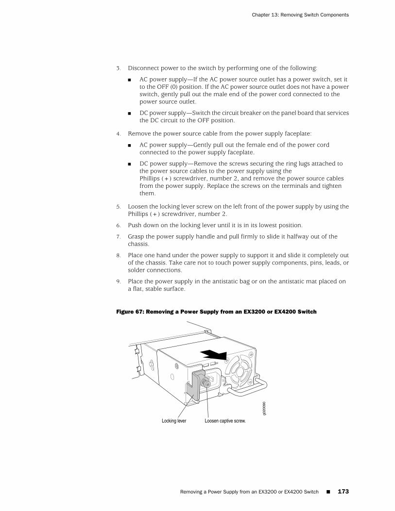
3. Disconnect power to the switch by performing one of the following:
■ AC power supply—If the AC power source outlet has a power switch, set itto the OFF (0) position. If the AC power source outlet does not have a powerswitch, gently pull out the male end of the power cord connected to thepower source outlet.
■ DC power supply—Switch the circuit breaker on the panel board that servicesthe DC circuit to the OFF position.
4. Remove the power source cable from the power supply faceplate:
■ AC power supply—Gently pull out the female end of the power cordconnected to the power supply faceplate.
■ DC power supply—Remove the screws securing the ring lugs attached tothe power source cables to the power supply using thePhillips (+) screwdriver, number 2, and remove the power source cablesfrom the power supply. Replace the screws on the terminals and tightenthem.
5. Loosen the locking lever screw on the left front of the power supply by using thePhillips (+) screwdriver, number 2.
6. Push down on the locking lever until it is in its lowest position.
7. Grasp the power supply handle and pull firmly to slide it halfway out of thechassis.
8. Place one hand under the power supply to support it and slide it completely outof the chassis. Take care not to touch power supply components, pins, leads, orsolder connections.
9. Place the power supply in the antistatic bag or on the antistatic mat placed ona flat, stable surface.
Figure 67: Removing a Power Supply from an EX3200 or EX4200 Switch
Removing a Power Supply from an EX3200 or EX4200 Switch ■ 173
Chapter 13: Removing Switch Components
Related Topics ■ Installing a Power Supply in an EX3200 or EX4200 Switch on page 130
■ Installing and Removing EX3200 and EX4200 Switch Hardware Components onpage 129
■ Power Supply in EX3200 and EX4200 Switches on page 26
■ Field-Replaceable Units in EX3200 and EX4200 Switches on page 16
■ AC Power Cord Specifications for EX3200 and EX4200 Switches on page 98
■ Rear Panel of an EX3200 Switch on page 9
■ Rear Panel of an EX4200 Switch on page 11
Removing a Fan Tray from an EX3200 or EX4200 Switch
EX3200 and EX4200 switches have a single field-replaceable unit (FRU) fan tray onthe rear panel. The fan tray is a hot-removable and hot-insertable FRU: You canremove and replace it without powering off the switch or disrupting switch functions.
Before you begin removing a fan tray from an EX3200 or EX4200 switch, ensurethat you have taken the necessary precautions to prevent ESD damage (see“Prevention of Electrostatic Discharge Damage on EX Series Switches” on page 236).
Ensure that you have the following parts and tools available to remove a fan trayfrom an EX3200 or EX4200 switch chassis:
■ Electrostatic discharge (ESD) grounding strap
■ Phillips (+) screwdriver, number 2
■ An antistatic bag or an antistatic mat
To remove a fan tray from an EX3200 or EX4200 switch (see Figure 68 on page 175and Figure 69 on page 175):
1. Place the antistatic bag or the antistatic mat on a flat, stable surface.
2. Attach the electrostatic discharge (ESD) grounding strap to your bare wrist, andconnect the strap to the ESD point on the chassis.
3. Loosen the screw or screws securing the fan tray by using thePhillips (+) screwdriver, number 2.
WARNING: To avoid injury, do not touch the fan with your hands or any tools asyou slide the fan tray out of the chassis—the fan may still be running.
4. Grasp the handle on the fan tray and pull firmly to slide the fan tray halfway outof the chassis.
5. When the fan stops spinning, slide the fan tray completely out of the chassis.
6. Place the fan tray in the antistatic bag or on the antistatic mat placed on a flat,stable surface.
174 ■ Removing a Fan Tray from an EX3200 or EX4200 Switch
Complete Hardware Guide for EX3200 and EX4200 Ethernet Switches
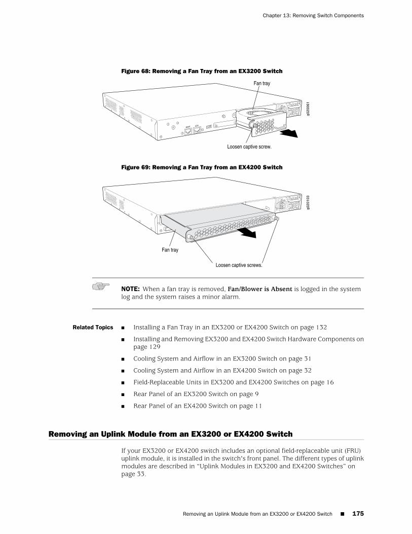
Figure 68: Removing a Fan Tray from an EX3200 Switch
Figure 69: Removing a Fan Tray from an EX4200 Switch
NOTE: When a fan tray is removed, Fan/Blower is Absent is logged in the systemlog and the system raises a minor alarm.
Related Topics ■ Installing a Fan Tray in an EX3200 or EX4200 Switch on page 132
■ Installing and Removing EX3200 and EX4200 Switch Hardware Components onpage 129
■ Cooling System and Airflow in an EX3200 Switch on page 31
■ Cooling System and Airflow in an EX4200 Switch on page 32
■ Field-Replaceable Units in EX3200 and EX4200 Switches on page 16
■ Rear Panel of an EX3200 Switch on page 9
■ Rear Panel of an EX4200 Switch on page 11
Removing an Uplink Module from an EX3200 or EX4200 Switch
If your EX3200 or EX4200 switch includes an optional field-replaceable unit (FRU)uplink module, it is installed in the switch's front panel. The different types of uplinkmodules are described in “Uplink Modules in EX3200 and EX4200 Switches” onpage 33.
Removing an Uplink Module from an EX3200 or EX4200 Switch ■ 175
Chapter 13: Removing Switch Components
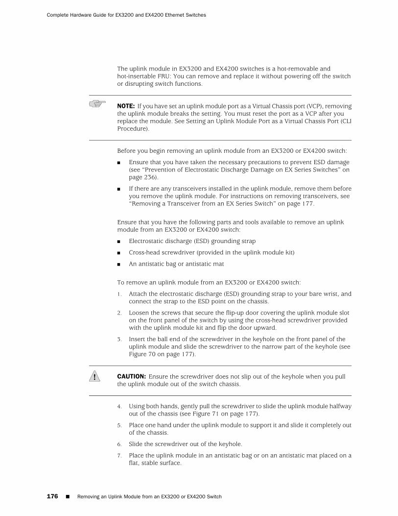
The uplink module in EX3200 and EX4200 switches is a hot-removable andhot-insertable FRU: You can remove and replace it without powering off the switchor disrupting switch functions.
NOTE: If you have set an uplink module port as a Virtual Chassis port (VCP), removingthe uplink module breaks the setting. You must reset the port as a VCP after youreplace the module. See Setting an Uplink Module Port as a Virtual Chassis Port (CLIProcedure).
Before you begin removing an uplink module from an EX3200 or EX4200 switch:
■ Ensure that you have taken the necessary precautions to prevent ESD damage(see “Prevention of Electrostatic Discharge Damage on EX Series Switches” onpage 236).
■ If there are any transceivers installed in the uplink module, remove them beforeyou remove the uplink module. For instructions on removing transceivers, see“Removing a Transceiver from an EX Series Switch” on page 177.
Ensure that you have the following parts and tools available to remove an uplinkmodule from an EX3200 or EX4200 switch:
■ Electrostatic discharge (ESD) grounding strap
■ Cross-head screwdriver (provided in the uplink module kit)
■ An antistatic bag or antistatic mat
To remove an uplink module from an EX3200 or EX4200 switch:
1. Attach the electrostatic discharge (ESD) grounding strap to your bare wrist, andconnect the strap to the ESD point on the chassis.
2. Loosen the screws that secure the flip-up door covering the uplink module sloton the front panel of the switch by using the cross-head screwdriver providedwith the uplink module kit and flip the door upward.
3. Insert the ball end of the screwdriver in the keyhole on the front panel of theuplink module and slide the screwdriver to the narrow part of the keyhole (seeFigure 70 on page 177).
CAUTION: Ensure the screwdriver does not slip out of the keyhole when you pullthe uplink module out of the switch chassis.
4. Using both hands, gently pull the screwdriver to slide the uplink module halfwayout of the chassis (see Figure 71 on page 177).
5. Place one hand under the uplink module to support it and slide it completely outof the chassis.
6. Slide the screwdriver out of the keyhole.
7. Place the uplink module in an antistatic bag or on an antistatic mat placed on aflat, stable surface.
176 ■ Removing an Uplink Module from an EX3200 or EX4200 Switch
Complete Hardware Guide for EX3200 and EX4200 Ethernet Switches
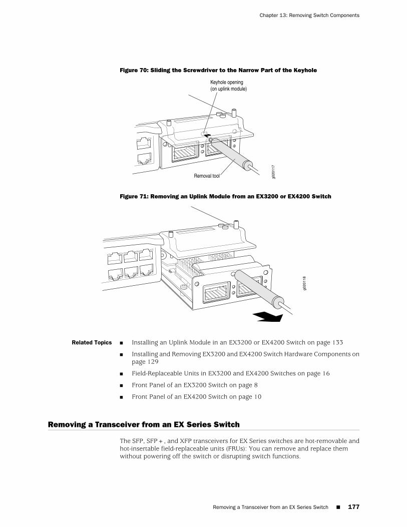
Figure 70: Sliding the Screwdriver to the Narrow Part of the Keyhole
Figure 71: Removing an Uplink Module from an EX3200 or EX4200 Switch
Related Topics ■ Installing an Uplink Module in an EX3200 or EX4200 Switch on page 133
■ Installing and Removing EX3200 and EX4200 Switch Hardware Components onpage 129
■ Field-Replaceable Units in EX3200 and EX4200 Switches on page 16
■ Front Panel of an EX3200 Switch on page 8
■ Front Panel of an EX4200 Switch on page 10
Removing a Transceiver from an EX Series Switch
The SFP, SFP+, and XFP transceivers for EX Series switches are hot-removable andhot-insertable field-replaceable units (FRUs): You can remove and replace themwithout powering off the switch or disrupting switch functions.
Removing a Transceiver from an EX Series Switch ■ 177
Chapter 13: Removing Switch Components
Before you begin removing a transceiver from an EX Series switch, ensure that youhave taken the necessary precautions for safe handling of lasers (see “Laser and LEDSafety Guidelines and Warnings for EX Series Switches” on page 213).
Ensure that you have the following parts and tools available:
■ An antistatic bag or an antistatic mat
■ Needlenose pliers
■ Rubber safety caps to cover the transceiver and fiber-optic cable connector
■ A dust cover to cover the port
Figure 72 on page 179 shows how to remove an SFP transceiver. The procedure isthe same for all transceiver types.
To remove a transceiver from an EX Series switch:
1. Place the antistatic bag or antistatic mat on a flat, stable surface.
2. Label the cable connected to the transceiver so that you can reconnect it correctly.
WARNING: Do not look directly into a fiber-optic transceiver or into the ends offiber-optic cables. Fiber-optic transceivers and fiber-optic cables connected totransceivers emit laser light that can damage your eyes.
WARNING: Do not leave a fiber-optic transceiver uncovered except when insertingor removing a cable. The rubber safety cap keeps the port clean and preventsaccidental exposure to laser light.
CAUTION: Do not bend fiber-optic cables beyond their minimum bend radius. Anarc smaller than a few inches in diameter can damage the cables and cause problemsthat are difficult to diagnose.
3. Remove the cable connected to the transceiver (see “Disconnecting a Fiber-OpticCable from an EX Series Switch” on page 179). Cover the transceiver and the endof each fiber-optic cable connector with a rubber safety cap immediately afterdisconnecting the fiber-optic cables.
4. Using your fingers, pull the ejector lever on the transceiver to unlock thetransceiver.
CAUTION: Before removing the transceiver, make sure you open the ejector levercompletely until you hear it click. This prevents damage to the transceiver.
5. Using the needlenose pliers, pull the ejector lever out from the transceiver.
178 ■ Removing a Transceiver from an EX Series Switch
Complete Hardware Guide for EX3200 and EX4200 Ethernet Switches
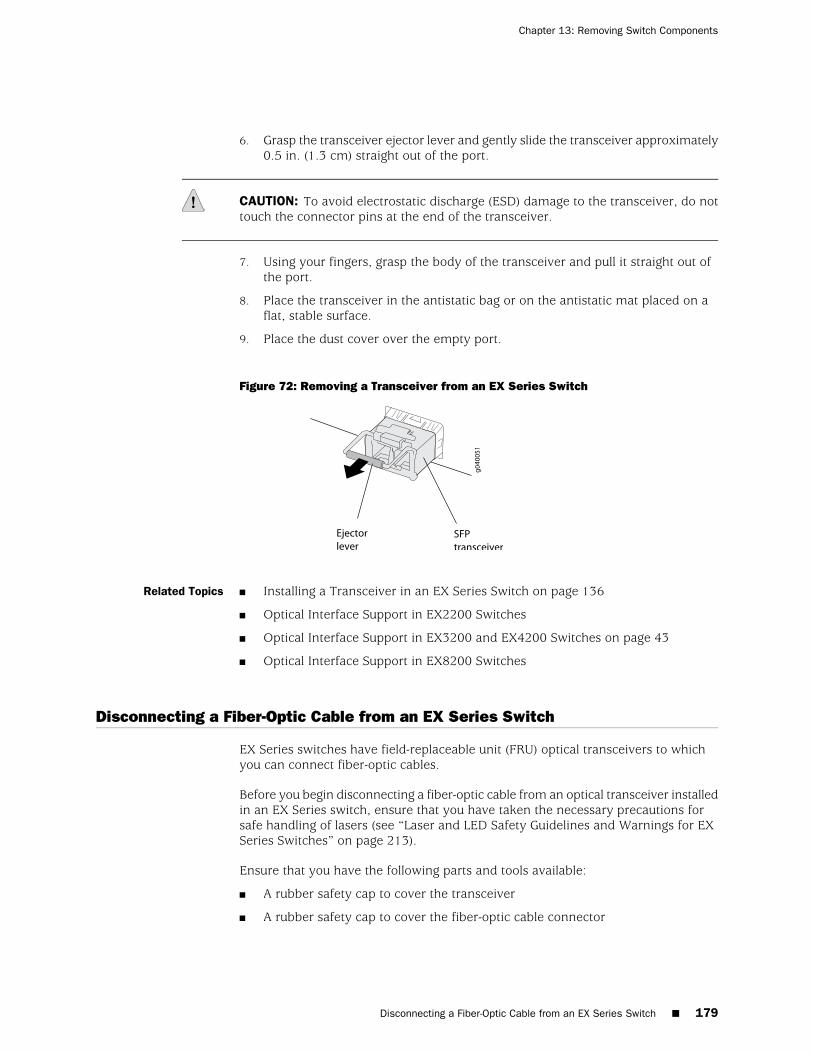
6. Grasp the transceiver ejector lever and gently slide the transceiver approximately0.5 in. (1.3 cm) straight out of the port.
CAUTION: To avoid electrostatic discharge (ESD) damage to the transceiver, do nottouch the connector pins at the end of the transceiver.
7. Using your fingers, grasp the body of the transceiver and pull it straight out ofthe port.
8. Place the transceiver in the antistatic bag or on the antistatic mat placed on aflat, stable surface.
9. Place the dust cover over the empty port.
Figure 72: Removing a Transceiver from an EX Series Switch
Related Topics ■ Installing a Transceiver in an EX Series Switch on page 136
■ Optical Interface Support in EX2200 Switches
■ Optical Interface Support in EX3200 and EX4200 Switches on page 43
■ Optical Interface Support in EX8200 Switches
Disconnecting a Fiber-Optic Cable from an EX Series Switch
EX Series switches have field-replaceable unit (FRU) optical transceivers to whichyou can connect fiber-optic cables.
Before you begin disconnecting a fiber-optic cable from an optical transceiver installedin an EX Series switch, ensure that you have taken the necessary precautions forsafe handling of lasers (see “Laser and LED Safety Guidelines and Warnings for EXSeries Switches” on page 213).
Ensure that you have the following parts and tools available:
■ A rubber safety cap to cover the transceiver
■ A rubber safety cap to cover the fiber-optic cable connector
Disconnecting a Fiber-Optic Cable from an EX Series Switch ■ 179
Chapter 13: Removing Switch Components
To disconnect a fiber-optic cable from an optical transceiver installed in an EX Seriesswitch:
1. Disable the port in which the transceiver is installed by issuing the command:
[edit interfaces]
user@switch# set interface-name disable
WARNING: Do not look directly into a fiber-optic transceiver or into the ends offiber-optic cables. Fiber-optic transceivers and fiber-optic cables connected totransceivers emit laser light that can damage your eyes.
2. Carefully unplug the fiber-optic cable connector from the transceiver.
3. Cover the transceiver with a rubber safety cap.
WARNING: Do not leave a fiber-optic transceiver uncovered except when insertingor removing a cable. The rubber safety cap keeps the port clean and preventsaccidental exposure to laser light.
4. Cover the fiber-optic cable connector with the rubber safety cap.
Related Topics ■ Connecting a Fiber-Optic Cable to an EX Series Switch on page 159
■ Removing a Transceiver from an EX Series Switch on page 177
■ Maintaining Fiber-Optic Cables in EX Series Switches on page 187
■ Optical Interface Support in EX2200 Switches
■ Optical Interface Support in EX3200 and EX4200 Switches on page 43
■ Optical Interface Support in EX8200 Switches
Disconnecting a Virtual Chassis Cable from an EX4200 Switch
If you need to disconnect an EX4200 switch from a Virtual Chassis configuration,you need to disconnect the Virtual Chassis cable from the Virtual Chassis ports (VCPs).
Before you begin disconnecting a Virtual Chassis cable from an EX4200 switch,ensure that you have taken the necessary precautions to prevent ESD damage (see“Prevention of Electrostatic Discharge Damage on EX Series Switches” on page 236).
Ensure that you have the following parts and tools available to disconnect a VirtualChassis cable from an EX4200 switch:
■ Electrostatic discharge (ESD) grounding strap
■ Cross-head screwdriver
180 ■ Disconnecting a Virtual Chassis Cable from an EX4200 Switch
Complete Hardware Guide for EX3200 and EX4200 Ethernet Switches

To disconnect a Virtual Chassis cable from an EX4200 switch (see Figure 73 onpage 181):
1. Attach the electrostatic discharge (ESD) grounding strap to your bare wrist, andconnect the strap to the ESD point on the chassis.
2. Loosen the screws on the locking cover by using the cross-head screwdriver.
3. Slide the locking cover back.
4. Gently pull the release pull tab on the Virtual Chassis cable connector to releasethe lock holding the Virtual Chassis cable connector in the Virtual Chassis port.
5. Gently pull the Virtual Chassis cable connector out of the Virtual Chassis port.
Figure 73: Virtual Chassis Cable Connector in an EX4200 Switch
NOTE: If you order Virtual Chassis cables separately, you must reuse the lockingcovers provided with the original cable or order Virtual Chassis cable locking coversalso separately.
Related Topics ■ Connecting a Virtual Chassis Cable to an EX4200 Switch on page 137
■ Understanding Virtual Chassis Hardware Configuration on an EX4200 Switch onpage 101
■ Understanding Virtual Chassis Components
■ Planning the Virtual Chassis on page 102
■ Virtual Chassis Ports Connector Pinout Information for EX4200 Switches onpage 74
Disconnecting a Virtual Chassis Cable from an EX4200 Switch ■ 181
Chapter 13: Removing Switch Components
Replacing a Member Switch of a Virtual Chassis Configuration (CLI Procedure)
You can replace a member switch of a Virtual Chassis configuration without disruptingnetwork service for the other members. You can retain the existing configuration ofthe member switch and apply it to a new member switch, or you can free up themember ID and make it available for assignment to a new member switch.
To replace a member switch, use the procedure that matches what you need toaccomplish:
■ Remove, Repair, and Reinstall the Same Switch on page 182
■ Remove a Member Switch, Replace with a Different Switch, and Reapply theOld Configuration on page 182
■ Remove a Member Switch and Make Its Member ID Available for Reassignmentto a Different Switch on page 183
Remove, Repair, and Reinstall the Same Switch
If you need to repair a member switch, you can remove it from the Virtual Chassisconfiguration without disrupting network service for the other members. The masterstores the configuration of the member ID so that it can be reapplied when themember switch (with the same base MAC address) is reconnected.
1. Power off and disconnect the member switch to be repaired.
2. Repair, as necessary.
3. Reconnect and power on the member switch.
Remove a Member Switch, Replace with a Different Switch, and Reapply the OldConfiguration
If you are unable to repair a member switch, you can replace it with a differentmember switch and retain the old configuration. The master stores the configurationof the member that was removed. When you connect a different member switch,the master assigns a new member ID. But the old configuration is still stored underthe previous member ID of the previous member switch.
NOTE: If you have used a preprovisioned configuration, use the replace commandto change the serial number in the Virtual Chassis configuration file. Substitute theserial number of the replacement member switch (on the back of the switch) for theserial number of the member switch that was removed.
1. Power off and disconnect the member switch to be replaced.
2. If the replacement member switch has been previously configured, revert thatswitch’s configuration to the factory defaults. See Reverting to the Default FactoryConfiguration for the EX Series Switch.
3. Connect and power on the replacement member switch.
182 ■ Replacing a Member Switch of a Virtual Chassis Configuration (CLI Procedure)
Complete Hardware Guide for EX3200 and EX4200 Ethernet Switches
4. Note the member ID displayed on the front panel.
5. Issue the request virtual-chassis renumber command from the Virtual Chassismaster to change the member switch’s current member ID to the member IDthat belonged to the member switch that was removed from the Virtual Chassisconfiguration).
Remove a Member Switch and Make Its Member ID Available for Reassignment to aDifferent Switch
When you remove a member switch from the Virtual Chassis configuration, themaster keeps its member ID on reserve. To make that member switch’s member IDavailable for reassignment, issue the request virtual-chassis recycle command fromthe Virtual Chassis master.
NOTE: When you add or delete members in a Virtual Chassis configuration, internalrouting changes might cause temporary traffic loss for a few seconds.
Related Topics ■ Monitoring Virtual Chassis Configuration Status and Statistics
■ Adding a New Switch to an Existing Virtual Chassis Configuration (CLI Procedure)on page 105
Remove a Member Switch and Make Its Member ID Available for Reassignment to a Different Switch ■ 183
Chapter 13: Removing Switch Components

184 ■ Remove a Member Switch and Make Its Member ID Available for Reassignment to a Different Switch
Complete Hardware Guide for EX3200 and EX4200 Ethernet Switches
Part 5
Switch and Component Maintenance
■ Routine Maintenance on page 187
Switch and Component Maintenance ■ 185

186 ■ Switch and Component Maintenance
Complete Hardware Guide for EX3200 and EX4200 Ethernet Switches
Chapter 14
Routine Maintenance
■ Maintaining Fiber-Optic Cables in EX Series Switches on page 187
Maintaining Fiber-Optic Cables in EX Series Switches
To maintain fiber-optic cables in EX Series switches:
■ When you unplug a fiber-optic cable from a transceiver, place rubber safety capsover the transceiver and on the end of the cable.
■ Anchor fiber-optic cable to avoid stress on the connectors. When attaching afiber-optic cable to a transceiver, be sure to secure the fiber-optic cable so thatit is not supporting its own weight as it hangs to the floor. Never let a fiber-opticcable hang free from the connector.
■ Avoid bending fiber-optic cables beyond their minimum bend radius. Bendingfiber-optic cables into arcs smaller than a few inches in diameter can damagethe cables and cause problems that are difficult to diagnose.
■ Frequent plugging and unplugging of fiber-optic cables in and out of opticalinstruments can damage the instruments, which are expensive to repair. Attacha short fiber extension to the optical equipment. Any wear and tear due tofrequent plugging and unplugging is then absorbed by the short fiber extension,which is easier and less expensive to replace than the instruments.
■ Keep fiber-optic cable connections clean. Micro-deposits of oil and dust in thecanal of the transceiver or cable connector can cause loss of light, reduction insignal power, and possibly intermittent problems with the optical connection.
To clean the transceiver canal, use an appropriate fiber-cleaning device such asRIFOCS Fiber Optic Adaptor Cleaning Wands (part number 946). Follow thedirections in the cleaning kit you use.
After cleaning the transceiver, make sure that the connector tip of the fiber-opticcable is clean. Use only an approved alcohol-free fiber-optic cable cleaning kitsuch as the Opptex Cletop-S® Fiber Cleaner. Follow the directions in the cleaningkit you use.
Related Topics ■ Handling and Storing Line Cards in EX8200 Switches
■ Maintaining Line Card Cables in EX8200 Switches
■ Installing a Transceiver in an EX Series Switch on page 136
■ Laser and LED Safety Guidelines and Warnings for EX Series Switches on page 213
Maintaining Fiber-Optic Cables in EX Series Switches ■ 187

■ Optical Interface Support in EX2200 Switches
■ Optical Interface Support in EX3200 and EX4200 Switches on page 43
■ Optical Interface Support in EX8200 Switches
188 ■ Maintaining Fiber-Optic Cables in EX Series Switches
Complete Hardware Guide for EX3200 and EX4200 Ethernet Switches

Part 6
Troubleshooting Switch Components
■ Troubleshooting Switch Components on page 191
Troubleshooting Switch Components ■ 189

190 ■ Troubleshooting Switch Components
Complete Hardware Guide for EX3200 and EX4200 Ethernet Switches
Chapter 15
Troubleshooting Switch Components
■ Troubleshooting Network Interfaces on EX3200 and EX4200 Switches on page 191
■ Troubleshooting Uplink Module Installation or Replacement on EX3200 andEX4200 Switches on page 192
Troubleshooting Network Interfaces on EX3200 and EX4200 Switches
This topic provides troubleshooting information for specific problems related tointerfaces on EX3200 and EX4200 switches.
■ The interface on one of the last four built-in network ports in an EX3200 switch(for example, interface ge-0/0/23) is down on page 191
■ The interface on the port in which an SFP or SFP+ transceiver is installed in anSFP+ uplink module is down on page 192
The interface on one of the last four built-in network ports in an EX3200 switch (forexample, interface ge-0/0/23) is down
Problem The interface on one of the last four built-in ports (ge-0/0/20 through ge-0/0/23 on24-port models or ge-0/0/44 through ge-0/0/47 on 48-port models) of an EX3200switch is down.
An SFP or SFP+ uplink module is installed in the switch and a transceiver is installedin one of the ports on the uplink module.
When you check the status with the CLI command show interfaces ge- or with theJ-Web user interface, the disabled port is not listed.
Cause The last four built-in ports use the same ASIC as the SFP uplink module. Therefore,if you install a transceiver in an SFP or SFP+ uplink module installed in an EX3200switch, a corresponding base port from the last four built-in ports is disabled.
Solution If you need to use the disabled built-in port, you must remove the transceiver fromthe SFP or SFP+ uplink module. Alternatively, you can install an XFP uplink moduleinstead of an SFP or SFP+ uplink module. There is no conflict between the built-innetwork ports and the ports on the XFP uplink modules.
Troubleshooting Network Interfaces on EX3200 and EX4200 Switches ■ 191
The interface on the port in which an SFP or SFP+ transceiver is installed in an SFP+uplink module is down
Problem The interface on the port in which an SFP or SFP+ transceiver is installed in anSFP+ uplink module installed in an EX3200 or EX4200 switch is down.
When you check the status with the CLI command show interfaces ge- or with theJ-Web user interface, the disabled port is not listed.
Cause By default, the SFP+ uplink module operates in the 10-gigabit mode and supportsonly SFP+ transceivers. The operating mode for the module is incorrectly set.
Solution Either SFP+ or SFP transceivers can be installed in SFP+ uplink modules. You mustconfigure the operating mode of the SFP+ uplink module to match the type oftransceiver you want to use. For SFP+ transceivers, configure the 10-gigabit operatingmode and for SFP transceivers, configure the 1-gigabit operating mode. See “Settingthe Mode on an SFP+ Uplink Module (CLI Procedure)” on page 168.
Related Topics ■ Troubleshooting Uplink Module Installation or Replacement on EX3200 andEX4200 Switches on page 192
■ Monitoring Interface Status and Traffic
■ Configuring Gigabit Ethernet Interfaces (CLI Procedure)
■ Configuring Gigabit Ethernet Interfaces (J-Web Procedure)
■ Removing a Transceiver from an EX Series Switch on page 177
■ Uplink Modules in EX3200 and EX4200 Switches on page 33
■ EX Series Switches Interfaces Overview
Troubleshooting Uplink Module Installation or Replacement on EX3200 and EX4200Switches
This topic provides troubleshooting information for specific problems related touplink module ports on EX3200 and EX4200 switches.
1. Virtual Chassis port (VCP) connection does not work on page 192
2. One of the last four network ports on an EX3200 switch with an SFP or SFP+uplink module installed is disabled on page 193
Virtual Chassis port (VCP) connection does not work
Problem The Virtual Chassis port (VCP) connection configured in an EX4200 switch does notwork.
A port of the uplink module is set as a VCP.
192 ■ The interface on the port in which an SFP or SFP+ transceiver is installed in an SFP+ uplink module is down
Complete Hardware Guide for EX3200 and EX4200 Ethernet Switches
Cause The uplink module installed in the switch was replaced.
Solution Set a port in the uplink module as a VCP. See Setting an Uplink Module Port as aVirtual Chassis Port (CLI Procedure).
One of the last four network ports on an EX3200 switch with an SFP or SFP+ uplink moduleinstalled is disabled
Problem One of the last four built-in ports (ge-0/0/20 through ge-0/0/23 on 24-port modelsor ge-0/0/44 through ge-0/0/47 on 48-port models) of an EX3200 switch with anSFP or SFP+ uplink module installed in it is disabled.
When you check the status with the CLI command show interfaces ge- or with theJ-Web user interface, the disabled port is not listed.
Cause The last four built-in ports use the same ASIC as the SFP uplink module. Therefore,if you install a transceiver in an SFP or SFP+ uplink module installed in an EX3200switch, a corresponding base port from the last four built-in ports is disabled.
Solution If you need to use the disabled built-in port, you must remove the transceiver fromthe SFP or SFP+ uplink module. Alternatively, you can install an XFP uplink moduleinstead of an SFP or SFP+ uplink module. There is no conflict between the built-innetwork ports and the ports on the XFP uplink modules.
Related Topics ■ Monitoring Interface Status and Traffic
■ Configuring Gigabit Ethernet Interfaces (CLI Procedure)
■ Configuring Gigabit Ethernet Interfaces (J-Web Procedure)
■ Installing an Uplink Module in an EX3200 or EX4200 Switch on page 133
■ Removing a Transceiver from an EX Series Switch on page 177
■ Uplink Modules in EX3200 and EX4200 Switches on page 33
■ Understanding Virtual Chassis Hardware Configuration on an EX4200 Switch onpage 101
One of the last four network ports on an EX3200 switch with an SFP or SFP+ uplink module installed is disabled ■ 193
Chapter 15: Troubleshooting Switch Components

194 ■ One of the last four network ports on an EX3200 switch with an SFP or SFP+ uplink module installed is disabled
Complete Hardware Guide for EX3200 and EX4200 Ethernet Switches

Part 7
Returning Hardware
■ Returning the Switch or Switch Components on page 197
Returning Hardware ■ 195

196 ■ Returning Hardware
Complete Hardware Guide for EX3200 and EX4200 Ethernet Switches
Chapter 16
Returning the Switch or SwitchComponents
■ Returning an EX3200 or EX4200 Switch or Component for Repair orReplacement on page 197
■ Locating the Serial Number on an EX3200 or EX4200 Switch orComponent on page 198
■ Contacting Customer Support to Obtain Return Materials Authorization for EXSeries Switches on page 199
■ Packing an EX3200 or EX4200 Switch or Component for Shipping on page 201
Returning an EX3200 or EX4200 Switch or Component for Repair or Replacement
If you need to return a switch or hardware component to Juniper Networks for repairor replacement, follow this procedure:
1. Determine the serial number of the component. For instructions, see “Locatingthe Serial Number on an EX3200 or EX4200 Switch or Component” on page 198.
2. Obtain an RMA number from JTAC as described in “Contacting Customer Supportto Obtain Return Materials Authorization for EX Series Switches” on page 199.
NOTE: Do not return any component to Juniper Networks unless you have firstobtained an RMA number. Juniper Networks reserves the right to refuse shipmentsthat do not have an RMA. Refused shipments are returned to the customer throughcollect freight.
3. Pack the switch or component for shipping as described in “Packing an EX3200or EX4200 Switch or Component for Shipping” on page 201.
For more information about return and repair policies, see the customer supportpage at http://www.juniper.net/support/guidelines.html.
Returning an EX3200 or EX4200 Switch or Component for Repair or Replacement ■ 197
Related Topics ■ EX3200 and EX4200 Switches Hardware Overview on page 3
Locating the Serial Number on an EX3200 or EX4200 Switch or Component
If you are returning a switch or hardware component to Juniper Networks for repairor replacement, you must locate the serial number of the switch or component. Youmust provide the serial number to the Juniper Networks Technical Assistance Center(JTAC) when you contact them to obtain Return Materials Authorization (RMA).
If the switch is operational and you can access the CLI, you can list serial numbersfor the switch and for some components with a CLI command. If you do not haveaccess to the CLI or if the serial number for the component does not appear in thecommand output, you can locate the serial number ID label on the physical switchor component (see Figure 74 on page 199 and Figure 75 on page 199).
NOTE: If you want to find the serial number on the physical switch component, youwill need to remove the component from the switch chassis, for which you musthave the required parts and tools available.
■ Listing the Switch and Components Details with the CLI on page 198
■ Locating the Chassis Serial Number ID Label on an EX3200 or EX4200Switch on page 198
■ Locating the Serial Number ID Labels on FRUs in an EX3200 or EX4200Switch on page 199
Listing the Switch and Components Details with the CLI
To list the switch and switch components and their serial numbers, enter the followingCLI command:
user@switch> show chassis hardwareHardware inventory:ItemVersion Part number Serial number DescriptionChassis AL0207391164 EX3200-48TFPC 0 REV X1 711-021265 AL0207391164 EX3200-48T, 8 POE CPUBUILTIN BUILTIN FPC CPU PIC 0 BUILTIN BUILTIN 48x 10/100/1000 Base-TFan TrayFan Tray
For information about the show chassis hardware command, see the JUNOS SoftwareSystem Basics and Services Command Reference athttp://www.juniper.net/techpubs/software/junos/junos101/index.html.
Locating the Chassis Serial Number ID Label on an EX3200 or EX4200 Switch
EX3200 and EX4200 switches have serial number ID labels located on the rear panelof the chassis (see Figure 74 on page 199 and Figure 75 on page 199).
198 ■ Locating the Serial Number on an EX3200 or EX4200 Switch or Component
Complete Hardware Guide for EX3200 and EX4200 Ethernet Switches
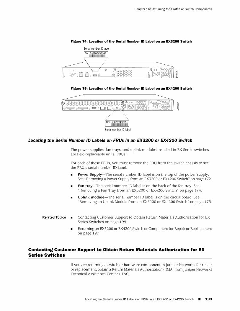
Figure 74: Location of the Serial Number ID Label on an EX3200 Switch
Figure 75: Location of the Serial Number ID Label on an EX4200 Switch
Locating the Serial Number ID Labels on FRUs in an EX3200 or EX4200 Switch
The power supplies, fan trays, and uplink modules installed in EX Series switchesare field-replaceable units (FRUs).
For each of these FRUs, you must remove the FRU from the switch chassis to seethe FRU’s serial number ID label.
■ Power Supply—The serial number ID label is on the top of the power supply.See “Removing a Power Supply from an EX3200 or EX4200 Switch” on page 172.
■ Fan tray—The serial number ID label is on the back of the fan tray. See“Removing a Fan Tray from an EX3200 or EX4200 Switch” on page 174.
■ Uplink module—The serial number ID label is on the circuit board. See“Removing an Uplink Module from an EX3200 or EX4200 Switch” on page 175.
Related Topics Contacting Customer Support to Obtain Return Materials Authorization for EXSeries Switches on page 199
■
■ Returning an EX3200 or EX4200 Switch or Component for Repair or Replacementon page 197
Contacting Customer Support to Obtain Return Materials Authorization for EXSeries Switches
If you are returning a switch or hardware component to Juniper Networks for repairor replacement, obtain a Return Materials Authorization (RMA) from Juniper NetworksTechnical Assistance Center (JTAC).
Locating the Serial Number ID Labels on FRUs in an EX3200 or EX4200 Switch ■ 199
Chapter 16: Returning the Switch or Switch Components

After locating the serial number of the switch or hardware component you want toreturn, open a Case with Juniper Networks Technical Assistance Center (JTAC) onthe Web or by telephone.
For instructions on locating the serial number of the switch or hardware componentyou want to return:
■ See Locating the Serial Number on an EX2200 Switch or Component.
■ See “Locating the Serial Number on an EX3200 or EX4200 Switch or Component”on page 198.
■ See Locating the Serial Number on an EX8200 Switch or Component.
Before you request an RMA from JTAC, be prepared to provide the followinginformation:
■ Your existing case number, if you have one
■ Serial number of the component
■ Your name, organization name, telephone number, fax number, and shippingaddress
■ Details of the failure or problem
■ Type of activity being performed on the switch when the problem occurred
■ Configuration data displayed by one or more show commands
You can contact JTAC 24 hours a day, seven days a week on the Web or by telephone:
■ Case Manager at CSC: http://www.juniper.net/cm/
■ Telephone: +1-888-314-JTAC1-888-314-5822, toll free in U.S., Canada, andMexico
NOTE: For international or direct-dial options in countries without toll free numbers,see http://www.juniper.net/support/requesting-support.html.
If you are contacting JTAC by telephone, enter your 11-digit case number followedby the pound (#) key for an existing case, or press the star (*) key to be routed tothe next available support engineer.
The support representative validates your request and issues an RMA number forreturn of the component.
Related Topics ■ Packing an EX2200 Switch or Component for Shipping
■ Packing an EX3200 or EX4200 Switch or Component for Shipping on page 201
■ Packing an EX8200 Switch or Component
■ Returning an EX2200 Switch or Component for Repair or Replacement
200 ■ Contacting Customer Support to Obtain Return Materials Authorization for EX Series Switches
Complete Hardware Guide for EX3200 and EX4200 Ethernet Switches

■ Returning an EX3200 or EX4200 Switch or Component for Repair or Replacementon page 197
■ Returning an EX8200 Switch or Component for Repair or Replacement
Packing an EX3200 or EX4200 Switch or Component for Shipping
If you are returning a switch or component to Juniper Networks for repair orreplacement, pack the item as described in this topic.
Before you begin packing an EX3200 and EX4200 switch or component, ensure thatyou have:
■ Taken the necessary precautions to prevent ESD damage (see “Prevention ofElectrostatic Discharge Damage on EX Series Switches” on page 236).
■ Retrieved the original shipping carton and packing materials. Contact your JTACrepresentative if you do not have these materials, to learn about approved packingmaterials. See “Contacting Customer Support to Obtain Return MaterialsAuthorization for EX Series Switches” on page 199.
Ensure that you have the following parts and tools available to pack an EX3200 orEX4200 switch:
■ Antistatic bag, one for each component
■ Electrostatic discharge (ESD) grounding strap
■ Phillips (+) screwdriver, number 2
This topic describes:
■ Packing an EX3200 or EX4200 Switch for Shipping on page 201
■ Packing EX3200 or EX4200 Switch Components for Shipping on page 202
Packing an EX3200 or EX4200 Switch for Shipping
To pack a switch for shipping:
1. Attach the electrostatic discharge (ESD) grounding strap to your bare wrist andconnect the strap to the ESD point on the chassis or to an outside ESD point ifthe switch is disconnected from earth ground. For more information about ESD,see “Prevention of Electrostatic Discharge Damage on EX Series Switches” onpage 236.
2. On the console or other management device connected to the switch (to themaster switch in a Virtual Chassis configuration), enter the CLI operational modeand issue the following command to shut down the switch software:
user@switch> request system halt
Wait until a message appears on the console confirming that the operating systemhas halted. For information about the request system halt command, see the
Packing an EX3200 or EX4200 Switch or Component for Shipping ■ 201
Chapter 16: Returning the Switch or Switch Components
JUNOS Software System Basics and Services Command Reference athttp://www.juniper.net/techpubs/software/junos/junos101/index.html.
3. Disconnect power from the switch by performing one of the following:
■ If the power source outlet has a power switch, set it to the OFF (0) position.
■ If the power source outlet does not have a power switch, gently pull out themale end of the power cord connected to the power source outlet.
4. Remove the cables that connect the switch to all external devices.
5. Remove all field-replaceable units (FRUs) from the switch.
6. If the switch is installed on a wall, rack, or cabinet, have one person support theweight of the switch while another person unscrews and removes the mountingscrews. Use the Phillips (+) screwdriver, number 2 to remove the screws.
7. Remove the switch from the wall, rack, cabinet, or desk (see “Chassis LiftingGuidelines for EX3200 and EX4200 Switches” on page 220) and place the switchin an antistatic bag.
8. Place the switch in the shipping carton.
9. Place the packing foam on top of and around the switch.
10. If you are returning accessories or FRUs with the switch, pack them as instructedin “Packing EX3200 or EX4200 Switch Components for Shipping” on page 202.
11. Replace the accessory box on top of the packing foam.
12. Close the top of the cardboard shipping box and seal it with packing tape.
13. Write the RMA number on the exterior of the box to ensure proper tracking.
Packing EX3200 or EX4200 Switch Components for Shipping
CAUTION: Do not stack switch components. Return individual components in separateboxes if they do not fit together on one level in the shipping box.
To pack and ship EX Series switch components:
■ Place individual boards in antistatic bags.
■ Ensure that the components are adequately protected with packing materialsand packed so that the pieces are prevented from moving around inside thecarton.
■ Close the top of the cardboard shipping box and seal it with packing tape.
■ Write the RMA number on the exterior of the box to ensure proper tracking.
Related Topics ■ Returning an EX3200 or EX4200 Switch or Component for Repair or Replacementon page 197
■ Removing a Fan Tray from an EX3200 or EX4200 Switch on page 174
■ Removing a Power Supply from an EX3200 or EX4200 Switch on page 172
202 ■ Packing EX3200 or EX4200 Switch Components for Shipping
Complete Hardware Guide for EX3200 and EX4200 Ethernet Switches

■ Removing an Uplink Module from an EX3200 or EX4200 Switch on page 175
■ Removing a Transceiver from an EX Series Switch on page 177
Packing EX3200 or EX4200 Switch Components for Shipping ■ 203
Chapter 16: Returning the Switch or Switch Components

204 ■ Packing EX3200 or EX4200 Switch Components for Shipping
Complete Hardware Guide for EX3200 and EX4200 Ethernet Switches

Part 8
Safety Information
■ General Safety Information on page 207
■ Radiation and Laser Warnings on page 213
■ Installation and Maintenance Safety Information on page 219
■ Power and Electrical Safety Information on page 235
Safety Information ■ 205

206 ■ Safety Information
Complete Hardware Guide for EX3200 and EX4200 Ethernet Switches

Chapter 17
General Safety Information
■ General Safety Guidelines and Warnings for EX Series Switches on page 207
■ Definitions of Safety Warning Levels for EX Series Switches on page 208
■ Fire Safety Requirements for EX Series Switches on page 210
■ Qualified Personnel Warning for EX Series Switches on page 211
■ Warning Statement for Norway and Sweden for EX Series Switches on page 212
General Safety Guidelines and Warnings for EX Series Switches
The following guidelines help ensure your safety and protect the EX Series switchfrom damage. The list of guidelines might not address all potentially hazardoussituations in your working environment, so be alert and exercise good judgment atall times.
■ Perform only the procedures explicitly described in the hardware documentationfor this product. Make sure that only authorized service personnel perform othersystem services.
■ Keep the area around the chassis clear and free from dust before, during, andafter installation.
■ Keep tools away from areas where people could trip over them while walking.
■ Do not wear loose clothing or jewelry, such as rings, bracelets, or chains, whichcould become caught in the chassis.
■ Wear safety glasses if you are working under any conditions that could behazardous to your eyes.
■ Do not perform any actions that create a potential hazard to people or make theequipment unsafe.
■ Never attempt to lift an object that is too heavy for one person to handle.
■ Never install or manipulate wiring during electrical storms.
■ Never install electrical jacks in wet locations unless the jacks are specificallydesigned for wet environments.
■ Operate the EX Series switch only when it is properly grounded.
■ Ensure that the separate protective earthing terminal provided on this productis permanently connected to earth.
■ Replace fuses only with fuses of the same type and rating.
General Safety Guidelines and Warnings for EX Series Switches ■ 207
■ Do not open or remove chassis covers or sheet-metal parts unless instructionsare provided in the hardware documentation for this product. Such an actioncould cause severe electrical shock.
■ Do not push or force any objects through any opening in the chassis frame. Suchan action could result in electrical shock or fire.
■ Avoid spilling liquid onto the EX Series switch chassis or onto any switchcomponent. Such an action could cause electrical shock or damage the switch.
■ Avoid touching uninsulated electrical wires or terminals that have not beendisconnected from their power source. Such an action could cause electricalshock.
■ Always ensure that all modules, power supplies, and cover panels are fullyinserted and that the installation screws are fully tightened.
Related Topics ■ AC Power Electrical Safety Guidelines for EX Series Switches on page 238
■ DC Power Electrical Safety Guidelines for EX Series Switches on page 241
■ General Electrical Safety Guidelines and Warnings for EX Series Switches onpage 235
■ Maintenance and Operational Safety Guidelines and Warnings for EX SeriesSwitches on page 227
■ Laser and LED Safety Guidelines and Warnings for EX Series Switches on page 213
■ Installation Instructions Warning for EX Series Switches on page 219
■ Grounded Equipment Warning for EX Series Switches on page 226
Definitions of Safety Warning Levels for EX Series Switches
The documentation for EX Series switches uses the following levels of safety warnings(there are two “Warning” formats):
NOTE: You might find this information helpful in a particular situation, or you mightoverlook this important information if it was not highlighted in a Note.
CAUTION: You need to observe the specified guidelines to avoid minor injury ordiscomfort to you or severe damage to the EX Series switch.
WARNING: This symbol alerts you to the risk of personal injury from a laser.
208 ■ Definitions of Safety Warning Levels for EX Series Switches
Complete Hardware Guide for EX3200 and EX4200 Ethernet Switches
WARNING: This symbol means danger. You are in a situation that could cause bodilyinjury. Before you work on any equipment, be aware of the hazards involved withelectrical circuitry and be familiar with standard practices for preventing accidents.
WARNING: Waarschuwing Dit waarschuwingssymbool betekent gevaar. U verkeertin een situatie die lichamelijk letsel kan veroorzaken. Voordat u aan enige apparatuurgaat werken, dient u zich bewust te zijn van de bij elektrische schakelingen betrokkenrisico's en dient u op de hoogte te zijn van standaard maatregelen om ongelukkente voorkomen.
WARNING: Varoitus Tämä varoitusmerkki merkitsee vaaraa. Olet tilanteessa, jokavoi johtaa ruumiinvammaan. Ennen kuin työskentelet minkään laitteiston parissa,ota selvää sähkökytkentöihin liittyvistä vaaroista ja tavanomaisista onnettomuuksienehkäisykeinoista.
WARNING: Attention Ce symbole d'avertissement indique un danger. Vous voustrouvez dans une situation pouvant causer des blessures ou des dommages corporels.Avant de travailler sur un équipement, soyez conscient des dangers posés par lescircuits électriques et familiarisez-vous avec les procédures couramment utiliséespour éviter les accidents.
WARNING: Warnung Dieses Warnsymbol bedeutet Gefahr. Sie befinden sich in einerSituation, die zu einer Körperverletzung führen könnte. Bevor Sie mit der Arbeit anirgendeinem Gerät beginnen, seien Sie sich der mit elektrischen Stromkreisenverbundenen Gefahren und der Standardpraktiken zur Vermeidung von Unfällenbewußt.
WARNING: Avvertenza Questo simbolo di avvertenza indica un pericolo. La situazionepotrebbe causare infortuni alle persone. Prima di lavorare su qualsiasi apparecchiatura,occorre conoscere i pericoli relativi ai circuiti elettrici ed essere al corrente dellepratiche standard per la prevenzione di incidenti.
WARNING: Advarsel Dette varselsymbolet betyr fare. Du befinner deg i en situasjonsom kan føre til personskade. Før du utfører arbeid på utstyr, må du vare oppmerksompå de faremomentene som elektriske kretser innebærer, samt gjøre deg kjent medvanlig praksis når det gjelder å unngå ulykker.
Definitions of Safety Warning Levels for EX Series Switches ■ 209
Chapter 17: General Safety Information
WARNING: Aviso Este símbolo de aviso indica perigo. Encontra-se numa situaçãoque lhe poderá causar danos físicos. Antes de começar a trabalhar com qualquerequipamento, familiarize-se com os perigos relacionados com circuitos eléctricos, ecom quaisquer práticas comuns que possam prevenir possíveis acidentes.
WARNING: ¡Atención! Este símbolo de aviso significa peligro. Existe riesgo para suintegridad física. Antes de manipular cualquier equipo, considerar los riesgos queentraña la corriente eléctrica y familiarizarse con los procedimientos estándar deprevención de accidentes.
WARNING: Varning! Denna varningssymbol signalerar fara. Du befinner dig i ensituation som kan leda till personskada. Innan du utför arbete på någon utrustningmåste du vara medveten om farorna med elkretsar och känna till vanligt förfarandeför att förebygga skador.
Related Topics ■ Warning Statement for Norway and Sweden for EX Series Switches on page 212
■ General Safety Guidelines and Warnings for EX Series Switches on page 207
■ Installation Instructions Warning for EX Series Switches on page 219
■ Maintenance and Operational Safety Guidelines and Warnings for EX SeriesSwitches on page 227
■ Grounded Equipment Warning for EX Series Switches on page 226
■ Laser and LED Safety Guidelines and Warnings for EX Series Switches on page 213
Fire Safety Requirements for EX Series Switches
In the event of a fire emergency involving switches and other network equipment,the safety of people is the primary concern. You should establish procedures forprotecting people in the event of a fire emergency, provide safety training, andproperly provision fire-control equipment and fire extinguishers.
In addition, you should establish procedures to protect your equipment in the eventof a fire emergency. Juniper Networks products should be installed in an environmentsuitable for electronic equipment. We recommend that fire suppression equipmentbe available in the event of a fire in the vicinity of the equipment and that all localfire, safety, and electrical codes and ordinances be observed when installing andoperating your equipment.
Fire Suppression
In the event of an electrical hazard or an electrical fire, you should first turn poweroff to the equipment at the source. Then use a Type C fire extinguisher, which usesnoncorrosive fire retardants, to extinguish the fire.
210 ■ Fire Safety Requirements for EX Series Switches
Complete Hardware Guide for EX3200 and EX4200 Ethernet Switches
Fire Suppression Equipment
Type C fire extinguishers, which use noncorrosive fire retardants such as carbondioxide and Halotron™, are most effective for suppressing electrical fires. Type C fireextinguishers displace oxygen from the point of combustion to eliminate the fire.For extinguishing fire on or around equipment that draws air from the environmentfor cooling, you should use this type of inert oxygen displacement extinguisherinstead of an extinguisher that leaves residues on equipment.
Do not use multipurpose Type ABC chemical fire extinguishers (dry chemical fireextinguishers). The primary ingredient in these fire extinguishers is monoammoniumphosphate, which is very sticky and difficult to clean. In addition, in the presence ofminute amounts of moisture, monoammonium phosphate can become highlycorrosive and corrodes most metals.
Any equipment in a room in which a chemical fire extinguisher has been dischargedis subject to premature failure and unreliable operation. The equipment is consideredto be irreparably damaged.
NOTE: To keep warranties effective, do not use a dry chemical fire extinguisher tocontrol a fire at or near a Juniper Networks switch. If a dry chemical fire extinguisheris used, the unit is no longer eligible for coverage under a service agreement.
We recommend that you dispose of any irreparably damaged equipment in anenvironmentally responsible manner.
Related Topics General Safety Guidelines and Warnings for EX Series Switches on page 207■
■ General Electrical Safety Guidelines and Warnings for EX Series Switches onpage 235
■ In Case of Electrical Accident: Action to Take on an EX Series Switch on page 248
Qualified Personnel Warning for EX Series Switches
WARNING: Only trained and qualified personnel should install or replace the EXSeries switch.
Waarschuwing Installatie en reparaties mogen uitsluitend door getraind en bevoegdpersoneel uitgevoerd worden.
Varoitus Ainoastaan koulutettu ja pätevä henkilökunta saa asentaa tai vaihtaa tämänlaitteen.
Attention Tout installation ou remplacement de l'appareil doit être réalisé par dupersonnel qualifié et compétent.
Qualified Personnel Warning for EX Series Switches ■ 211
Chapter 17: General Safety Information
Warnung Gerät nur von geschultem, qualifiziertem Personal installieren oderauswechseln lassen.
Avvertenza Solo personale addestrato e qualificato deve essere autorizzato adinstallare o sostituire questo apparecchio.
Advarsel Kun kvalifisert personell med riktig opplæring bør montere eller bytte utdette utstyret.
Aviso Este equipamento deverá ser instalado ou substituído apenas por pessoaldevidamente treinado e qualificado.
¡Atención! Estos equipos deben ser instalados y reemplazados exclusivamente porpersonal técnico adecuadamente preparado y capacitado.
Varning! Denna utrustning ska endast installeras och bytas ut av utbildad ochkvalificerad personal.
Related Topics ■ General Safety Guidelines and Warnings for EX Series Switches on page 207
■ General Electrical Safety Guidelines and Warnings for EX Series Switches onpage 235
■ AC Power Electrical Safety Guidelines for EX Series Switches on page 238
■ DC Power Electrical Safety Guidelines for EX Series Switches on page 241
Warning Statement for Norway and Sweden for EX Series Switches
WARNING: The equipment must be connected to an earthed mains socket-outlet.
Advarsel Apparatet skal kobles til en jordet stikkontakt.
Varning! Apparaten skall anslutas till jordat nätuttag.
Related Topics ■ General Safety Guidelines and Warnings for EX Series Switches on page 207
212 ■ Warning Statement for Norway and Sweden for EX Series Switches
Complete Hardware Guide for EX3200 and EX4200 Ethernet Switches

Chapter 18
Radiation and Laser Warnings
■ Laser and LED Safety Guidelines and Warnings for EX Series Switches on page 213
■ Radiation from Open Port Apertures Warning for EX Series Switches on page 216
Laser and LED Safety Guidelines and Warnings for EX Series Switches
EX Series switches are equipped with laser transmitters, which are considered aClass 1 Laser Product by the U.S. Food and Drug Administration and are evaluatedas a Class 1 Laser Product per EN 60825–1 requirements.
Observe the following guidelines and warnings:
■ General Laser Safety Guidelines on page 213
■ Class 1 Laser Product Warning on page 214
■ Class 1 LED Product Warning on page 214
■ Laser Beam Warning on page 215
General Laser Safety Guidelines
When working around ports that support optical transceivers, observe the followingsafety guidelines to prevent eye injury:
■ Do not look into unterminated ports or at fibers that connect to unknown sources.
■ Do not examine unterminated optical ports with optical instruments.
■ Avoid direct exposure to the beam.
WARNING: Unterminated optical connectors can emit invisible laser radiation. Thelens in the human eye focuses all the laser power on the retina, so focusing the eyedirectly on a laser source—even a low-power laser—could permanently damage theeye.
Laser and LED Safety Guidelines and Warnings for EX Series Switches ■ 213
Class 1 Laser Product Warning
WARNING: Class 1 laser product.
Waarschuwing Klasse-1 laser produkt.
Varoitus Luokan 1 lasertuote.
Attention Produit laser de classe I.
Warnung Laserprodukt der Klasse 1.
WARNING: Avvertenza Prodotto laser di Classe 1.
Advarsel Laserprodukt av klasse 1.
Aviso Produto laser de classe 1.
¡Atención! Producto láser Clase I.
Varning! Laserprodukt av klass 1.
Class 1 LED Product Warning
WARNING: Class 1 LED product.
Waarschuwing Klasse 1 LED-product.
Varoitus Luokan 1 valodiodituote.
Attention Alarme de produit LED Class I.
Warnung Class 1 LED-Produktwarnung.
WARNING: Avvertenza Avvertenza prodotto LED di Classe 1.
Advarsel LED-produkt i klasse 1.
Aviso Produto de classe 1 com LED.
214 ■ Laser and LED Safety Guidelines and Warnings for EX Series Switches
Complete Hardware Guide for EX3200 and EX4200 Ethernet Switches
¡Atención! Aviso sobre producto LED de Clase 1.
Varning! Lysdiodprodukt av klass 1.
Laser Beam Warning
WARNING: Do not stare into the laser beam or view it directly with opticalinstruments.
WARNING: Waarschuwing Niet in de straal staren of hem rechtstreeks bekijken metoptische instrumenten.
WARNING: Varoitus Älä katso säteeseen äläkä tarkastele sitä suoraan optisen laitteenavulla.
WARNING: Attention Ne pas fixer le faisceau des yeux, ni l'observer directement àl'aide d'instruments optiques.
WARNING: Warnung Nicht direkt in den Strahl blicken und ihn nicht direkt mitoptischen Geräten prüfen.
WARNING: Avvertenza Non fissare il raggio con gli occhi né usare strumenti otticiper osservarlo direttamente.
WARNING: Advarsel Stirr eller se ikke direkte p strlen med optiske instrumenter.
WARNING: Aviso Não olhe fixamente para o raio, nem olhe para ele directamentecom instrumentos ópticos.
WARNING: ¡Atención! No mirar fijamente el haz ni observarlo directamente coninstrumentos ópticos.
Laser and LED Safety Guidelines and Warnings for EX Series Switches ■ 215
Chapter 18: Radiation and Laser Warnings
WARNING: Varning! Rikta inte blicken in mot strålen och titta inte direkt på dengenom optiska instrument.
Related Topics ■ General Safety Guidelines and Warnings for EX Series Switches on page 207
■ Radiation from Open Port Apertures Warning for EX Series Switches on page 216
■ Installation Instructions Warning for EX Series Switches on page 219
■ Grounded Equipment Warning for EX Series Switches on page 226
■ Optical Interface Support in EX3200 and EX4200 Switches on page 43
■ Optical Interface Support in EX8200 Switches
■ Optical Interface Support in EX2200 Switches
Radiation from Open Port Apertures Warning for EX Series Switches
WARNING: Because invisible radiation might be emitted from the aperture of theport when no fiber cable is connected, avoid exposure to radiation and do not stareinto open apertures.
WARNING: Waarschuwing Aangezien onzichtbare straling vanuit de opening vande poort kan komen als er geen fiberkabel aangesloten is, dient blootstelling aanstraling en het kijken in open openingen vermeden te worden.
WARNING: Varoitus Koska portin aukosta voi emittoitua näkymätöntä säteilyä, kunkuitukaapelia ei ole kytkettynä, vältä säteilylle altistumista äläkä katso avoimiinaukkoihin.
WARNING: Attention Des radiations invisibles à l'il nu pouvant traverser l'ouverturedu port lorsqu'aucun câble en fibre optique n'y est connecté, il est recommandé dene pas regarder fixement l'intérieur de ces ouvertures.
WARNING: Warnung Aus der Port-Öffnung können unsichtbare Strahlen emittieren,wenn kein Glasfaserkabel angeschlossen ist. Vermeiden Sie es, sich den Strahlungenauszusetzen, und starren Sie nicht in die Öffnungen!
216 ■ Radiation from Open Port Apertures Warning for EX Series Switches
Complete Hardware Guide for EX3200 and EX4200 Ethernet Switches
WARNING: Avvertenza Quando i cavi in fibra non sono inseriti, radiazioni invisibilipossono essere emesse attraverso l'apertura della porta. Evitate di esporvi alleradiazioni e non guardate direttamente nelle aperture.
WARNING: Advarsel Unngå utsettelse for stråling, og stirr ikke inn i åpninger somer åpne, fordi usynlig stråling kan emiteres fra portens åpning når det ikke er tilkobleten fiberkabel.
WARNING: Aviso Dada a possibilidade de emissão de radiação invisível através doorifício da via de acesso, quando esta não tiver nenhum cabo de fibra conectado,deverá evitar a exposição à radiação e não deverá olhar fixamente para orifícios quese encontrarem a descoberto.
WARNING: ¡Atención! Debido a que la apertura del puerto puede emitir radiacióninvisible cuando no existe un cable de fibra conectado, evite mirar directamente alas aperturas para no exponerse a la radiación.
WARNING: Varning! Osynlig strålning kan avges från en portöppning utan anslutenfiberkabel och du bör därför undvika att bli utsatt för strålning genom att inte stirrain i oskyddade öppningar.
Related Topics ■ General Safety Guidelines and Warnings for EX Series Switches on page 207
■ Laser and LED Safety Guidelines and Warnings for EX Series Switches on page 213
■ Installation Instructions Warning for EX Series Switches on page 219
■ Grounded Equipment Warning for EX Series Switches on page 226
Radiation from Open Port Apertures Warning for EX Series Switches ■ 217
Chapter 18: Radiation and Laser Warnings

218 ■ Radiation from Open Port Apertures Warning for EX Series Switches
Complete Hardware Guide for EX3200 and EX4200 Ethernet Switches
Chapter 19
Installation and Maintenance SafetyInformation
■ Installation Instructions Warning for EX Series Switches on page 219
■ Chassis Lifting Guidelines for EX3200 and EX4200 Switches on page 220
■ Ramp Warning for EX Series Switches on page 221
■ Rack-Mounting and Cabinet-Mounting Warnings for EX SeriesSwitches on page 221
■ Wall-Mounting Warning for EX3200 and EX4200 Switches on page 225
■ Grounded Equipment Warning for EX Series Switches on page 226
■ Maintenance and Operational Safety Guidelines and Warnings for EX SeriesSwitches on page 227
Installation Instructions Warning for EX Series Switches
WARNING: Read the installation instructions before you connect the switch to apower source.
Waarschuwing Raadpleeg de installatie-aanwijzingen voordat u het systeem met devoeding verbindt.
Varoitus Lue asennusohjeet ennen järjestelmän yhdistämistä virtalähteeseen.
Attention Avant de brancher le système sur la source d'alimentation, consulter lesdirectives d'installation.
Warnung Lesen Sie die Installationsanweisungen, bevor Sie das System an dieStromquelle anschließen.
Avvertenza Consultare le istruzioni di installazione prima di collegare il sistemaall'alimentatore.
Advarsel Les installasjonsinstruksjonene før systemet kobles til strømkilden.
Aviso Leia as instruções de instalação antes de ligar o sistema à sua fonte de energia.
Installation Instructions Warning for EX Series Switches ■ 219
¡Atención! Ver las instrucciones de instalación antes de conectar el sistema a la redde alimentación.
Varning! Läs installationsanvisningarna innan du kopplar systemet till dessströmförsörjningsenhet.
Related Topics ■ General Safety Guidelines and Warnings for EX Series Switches on page 207
■ Laser and LED Safety Guidelines and Warnings for EX Series Switches on page 213
■ Grounded Equipment Warning for EX Series Switches on page 226
■ Connecting AC Power to an EX2200 Switch
■ Connecting AC Power to an EX3200 or EX4200 Switch on page 146
■ Connecting AC Power to an EX8200 Switch
■ Connecting DC Power to an EX3200 or EX4200 Switch on page 148
■ Connecting DC Power to an EX8200 Switch
Chassis Lifting Guidelines for EX3200 and EX4200 Switches
The weight of a fully loaded EX3200 or EX4200 switch chassis is approximately 22 lb(10 kg). Observe the following guidelines for lifting and moving an EX3200 or EX4200switch:
■ Before installing an EX3200 or EX4200 switch, read the guidelines in “SitePreparation Checklist for EX3200 and EX4200 Switches” on page 81 to verifythat the intended site meets the specified power, environmental, and clearancerequirements.
■ Before lifting or moving the EX3200 or EX4200 switch, disconnect all externalcables.
■ As when lifting any heavy object, lift most of the weight with your legs ratherthan your back. Keep your knees bent and your back relatively straight and avoidtwisting your body as you lift. Balance the load evenly and be sure that yourfooting is solid.
Related Topics General Safety Guidelines and Warnings for EX Series Switches on page 207■
■ Installation Instructions Warning for EX Series Switches on page 219
■ Mounting an EX3200 or EX4200 Switch on page 116
220 ■ Chassis Lifting Guidelines for EX3200 and EX4200 Switches
Complete Hardware Guide for EX3200 and EX4200 Ethernet Switches
Ramp Warning for EX Series Switches
WARNING: When installing the switch, do not use a ramp inclined at more than 10degrees.
Waarschuwing Gebruik een oprijplaat niet onder een hoek van meer dan 10 graden.
Varoitus Älä käytä sellaista kaltevaa pintaa, jonka kaltevuus ylittää 10 astetta.
Attention Ne pas utiliser une rampe dont l'inclinaison est supérieure à 10 degrés.
Warnung Keine Rampen mit einer Neigung von mehr als 10 Grad verwenden.
Avvertenza Non usare una rampa con pendenza superiore a 10 gradi.
Advarsel Bruk aldri en rampe som heller mer enn 10 grader.
Aviso Não utilize uma rampa com uma inclinação superior a 10 graus.
¡Atención! No usar una rampa inclinada más de 10 grados
Varning! Använd inte ramp med en lutning på mer än 10 grader.
Related Topics ■ General Safety Guidelines and Warnings for EX Series Switches on page 207
■ Laser and LED Safety Guidelines and Warnings for EX Series Switches on page 213
■ Installation Instructions Warning for EX Series Switches on page 219
■ Grounded Equipment Warning for EX Series Switches on page 226
Rack-Mounting and Cabinet-Mounting Warnings for EX Series Switches
Ensure that the rack or cabinet in which the EX Series switch is installed is evenlyand securely supported. Uneven mechanical loading could lead to a hazardouscondition.
WARNING: To prevent bodily injury when mounting or servicing the switch in a rack,take the following precautions to ensure that the system remains stable. The followingdirectives help maintain your safety:
■ The switch must be installed in a rack that is secured to the building structure.
■ The switch should be mounted at the bottom of the rack if it is the only unit inthe rack.
Ramp Warning for EX Series Switches ■ 221
Chapter 19: Installation and Maintenance Safety Information
■ When mounting the switch on a partially filled rack, load the rack from thebottom to the top with the heaviest component at the bottom of the rack.
■ If the rack is provided with stabilizing devices, install the stabilizers beforemounting or servicing the switch in the rack.
WARNING: Waarschuwing Om lichamelijk letsel te voorkomen wanneer u dit toestelin een rek monteert of het daar een servicebeurt geeft, moet u specialevoorzorgsmaatregelen nemen om ervoor te zorgen dat het toestel stabiel blijft. Deonderstaande richtlijnen worden verstrekt om uw veiligheid te verzekeren:
■ De Juniper Networks switch moet in een stellage worden geïnstalleerd die aaneen bouwsel is verankerd.
■ Dit toestel dient onderaan in het rek gemonteerd te worden als het toestel hetenige in het rek is.
■ Wanneer u dit toestel in een gedeeltelijk gevuld rek monteert, dient u het rekvan onderen naar boven te laden met het zwaarste onderdeel onderaan in hetrek.
■ Als het rek voorzien is van stabiliseringshulpmiddelen, dient u de stabilisatorente monteren voordat u het toestel in het rek monteert of het daar een servicebeurtgeeft.
WARNING: Varoitus Kun laite asetetaan telineeseen tai huolletaan sen ollessatelineessä, on noudatettava erityisiä varotoimia järjestelmän vakavuudensäilyttämiseksi, jotta vältytään loukkaantumiselta. Noudata seuraaviaturvallisuusohjeita:
■ Juniper Networks switch on asennettava telineeseen, joka on kiinnitettyrakennukseen.
■ Jos telineessä ei ole muita laitteita, aseta laite telineen alaosaan.
■ Jos laite asetetaan osaksi täytettyyn telineeseen, aloita kuormittaminen senalaosasta kaikkein raskaimmalla esineellä ja siirry sitten sen yläosaan.
■ Jos telinettä varten on vakaimet, asenna ne ennen laitteen asettamista telineeseentai sen huoltamista siinä.
WARNING: Attention Pour éviter toute blessure corporelle pendant les opérationsde montage ou de réparation de cette unité en casier, il convient de prendre des
222 ■ Rack-Mounting and Cabinet-Mounting Warnings for EX Series Switches
Complete Hardware Guide for EX3200 and EX4200 Ethernet Switches
précautions spéciales afin de maintenir la stabilité du système. Les directivesci-dessous sont destinées à assurer la protection du personnel:
■ Le rack sur lequel est monté le Juniper Networks switch doit être fixé à la structuredu bâtiment.
■ Si cette unité constitue la seule unité montée en casier, elle doit être placée dansle bas.
■ Si cette unité est montée dans un casier partiellement rempli, charger le casierde bas en haut en plaçant l'élément le plus lourd dans le bas.
■ Si le casier est équipé de dispositifs stabilisateurs, installer les stabilisateurs avantde monter ou de réparer l'unité en casier.
WARNING: Warnung Zur Vermeidung von Körperverletzung beim Anbringen oderWarten dieser Einheit in einem Gestell müssen Sie besondere Vorkehrungen treffen,um sicherzustellen, daß das System stabil bleibt. Die folgenden Richtlinien sollen zurGewährleistung Ihrer Sicherheit dienen:
■ Der Juniper Networks switch muß in einem Gestell installiert werden, das in derGebäudestruktur verankert ist.
■ Wenn diese Einheit die einzige im Gestell ist, sollte sie unten im Gestellangebracht werden.
■ Bei Anbringung dieser Einheit in einem zum Teil gefüllten Gestell ist das Gestellvon unten nach oben zu laden, wobei das schwerste Bauteil unten im Gestellanzubringen ist.
■ Wird das Gestell mit Stabilisierungszubehör geliefert, sind zuerst die Stabilisatorenzu installieren, bevor Sie die Einheit im Gestell anbringen oder sie warten.
WARNING: Avvertenza Per evitare infortuni fisici durante il montaggio o lamanutenzione di questa unità in un supporto, occorre osservare speciali precauzioniper garantire che il sistema rimanga stabile. Le seguenti direttive vengono forniteper garantire la sicurezza personale:
■ Il Juniper Networks switch deve essere installato in un telaio, il quale deve esserefissato alla struttura dell'edificio.
■ Questa unità deve venire montata sul fondo del supporto, se si tratta dell'unicaunità da montare nel supporto.
■ Quando questa unità viene montata in un supporto parzialmente pieno, caricareil supporto dal basso all'alto, con il componente più pesante sistemato sul fondodel supporto.
■ Se il supporto è dotato di dispositivi stabilizzanti, installare tali dispositivi primadi montare o di procedere alla manutenzione dell'unità nel supporto.
Rack-Mounting and Cabinet-Mounting Warnings for EX Series Switches ■ 223
Chapter 19: Installation and Maintenance Safety Information
WARNING: Advarsel Unngå fysiske skader under montering eller reparasjonsarbeidpå denne enheten når den befinner seg i et kabinett. Vær nøye med at systemet erstabilt. Følgende retningslinjer er gitt for å verne om sikkerheten:
■ Juniper Networks switch må installeres i et stativ som er forankret tilbygningsstrukturen.
■ Denne enheten bør monteres nederst i kabinettet hvis dette er den eneste enheteni kabinettet.
■ Ved montering av denne enheten i et kabinett som er delvis fylt, skal kabinettetlastes fra bunnen og opp med den tyngste komponenten nederst i kabinettet.
■ Hvis kabinettet er utstyrt med stabiliseringsutstyr, skal stabilisatorene installeresfør montering eller utføring av reparasjonsarbeid på enheten i kabinettet.
WARNING: Aviso Para se prevenir contra danos corporais ao montar ou reparar estaunidade numa estante, deverá tomar precauções especiais para se certificar de queo sistema possui um suporte estável. As seguintes directrizes ajudá-lo-ão a efectuaro seu trabalho com segurança:
■ O Juniper Networks switch deverá ser instalado numa prateleira fixa à estruturado edificio.
■ Esta unidade deverá ser montada na parte inferior da estante, caso seja esta aúnica unidade a ser montada.
■ Ao montar esta unidade numa estante parcialmente ocupada, coloque os itensmais pesados na parte inferior da estante, arrumando-os de baixo para cima.
■ Se a estante possuir um dispositivo de estabilização, instale-o antes de montarou reparar a unidade.
WARNING: ¡Atención! Para evitar lesiones durante el montaje de este equipo sobreun bastidor, o posteriormente durante su mantenimiento, se debe poner muchocuidado en que el sistema quede bien estable. Para garantizar su seguridad, procedasegún las siguientes instrucciones:
■ El Juniper Networks switch debe instalarse en un bastidor fijado a la estructuradel edificio.
■ Colocar el equipo en la parte inferior del bastidor, cuando sea la única unidaden el mismo.
224 ■ Rack-Mounting and Cabinet-Mounting Warnings for EX Series Switches
Complete Hardware Guide for EX3200 and EX4200 Ethernet Switches
■ Cuando este equipo se vaya a instalar en un bastidor parcialmente ocupado,comenzar la instalación desde la parte inferior hacia la superior colocando elequipo más pesado en la parte inferior.
■ Si el bastidor dispone de dispositivos estabilizadores, instalar éstos antes demontar o proceder al mantenimiento del equipo instalado en el bastidor.
WARNING: Varning! För att undvika kroppsskada när du installerar eller utförunderhållsarbete på denna enhet på en ställning måste du vidta särskildaförsiktighetsåtgärder för att försäkra dig om att systemet står stadigt. Följande riktlinjerges för att trygga din säkerhet:
■ Juniper Networks switch måste installeras i en ställning som är förankrad ibyggnadens struktur.
■ Om denna enhet är den enda enheten på ställningen skall den installeras längstned på ställningen.
■ Om denna enhet installeras på en delvis fylld ställning skall ställningen fyllasnedifrån och upp, med de tyngsta enheterna längst ned på ställningen.
■ Om ställningen är försedd med stabiliseringsdon skall dessa monteras fast innanenheten installeras eller underhålls på ställningen.
Related Topics ■ General Safety Guidelines and Warnings for EX Series Switches on page 207
■ Installation Instructions Warning for EX Series Switches on page 219
■ Grounded Equipment Warning for EX Series Switches on page 226
■ Mounting an EX2200 Switch
■ Mounting an EX3200 or EX4200 Switch on page 116
■ Mounting an EX8208 Switch on a Rack or Cabinet
■ Mounting an EX8216 Switch on a Rack or Cabinet
Wall-Mounting Warning for EX3200 and EX4200 Switches
WARNING: When mounted in a vertical position, an EX3200 or EX4200 chassis mustbe oriented with the front panel of the chassis pointing down to ensure proper airflowand meet safety requirements in the event of a fire.
Wall-Mounting Warning for EX3200 and EX4200 Switches ■ 225
Chapter 19: Installation and Maintenance Safety Information
WARNING: Avertissement: lorsqu’installé en position verticale, un châssis decommutation EX3200 ou EX4200 doit être orienté avec le panneau avant dirigé versle bas.
WARNING: Warnhinweis: Bei der Befestigung in vertikaler Position muss ein EX3200-oder EX4200-Switch-Gehäuse so ausgerichtet werden, dass das vordere Bedienfelddes Switch-Gehäuses nach unten zeigt.
Related Topics ■ Mounting an EX3200 or EX4200 Switch on a Wall on page 125
Grounded Equipment Warning for EX Series Switches
WARNING: The switch is intended to be grounded. During normal use, ensure thatyou have connected earth ground to the switch chassis.
Waarschuwing Deze apparatuur hoort geaard te worden Zorg dat de host-computertijdens normaal gebruik met aarde is verbonden.
Varoitus Tämä laitteisto on tarkoitettu maadoitettavaksi. Varmista, että isäntälaiteon yhdistetty maahan normaalikäytön aikana.
Attention Cet équipement doit être relié à la terre. S'assurer que l'appareil hôte estrelié à la terre lors de l'utilisation normale.
Warnung Dieses Gerät muß geerdet werden. Stellen Sie sicher, daß das Host-Gerätwährend des normalen Betriebs an Erde gelegt ist.
Avvertenza Questa apparecchiatura deve essere collegata a massa. Accertarsi che ildispositivo host sia collegato alla massa di terra durante il normale utilizzo.
Advarsel Dette utstyret skal jordes. Forviss deg om vertsterminalen er jordet vednormalt bruk.
Aviso Este equipamento deverá estar ligado à terra. Certifique-se que o host seencontra ligado à terra durante a sua utilização normal.
¡Atención! Este equipo debe conectarse a tierra. Asegurarse de que el equipo principalesté conectado a tierra durante el uso normal.
Varning! Denna utrustning är avsedd att jordas. Se till att värdenheten är jordad vidnormal användning.
Related Topics General Safety Guidelines and Warnings for EX Series Switches on page 207■
226 ■ Grounded Equipment Warning for EX Series Switches
Complete Hardware Guide for EX3200 and EX4200 Ethernet Switches
■ Connecting Earth Ground to an EX Series Switch on page 141
Maintenance and Operational Safety Guidelines and Warnings for EX SeriesSwitches
While performing the maintenance activities for EX Series switches, observe thefollowing guidelines and warnings:
■ Battery Handling Warning on page 227
■ Jewelry Removal Warning on page 228
■ Lightning Activity Warning on page 230
■ Operating Temperature Warning on page 231
■ Product Disposal Warning on page 232
Battery Handling Warning
WARNING: Replacing a battery incorrectly might result in an explosion. Replace abattery only with the same or equivalent type recommended by the manufacturer.Dispose of used batteries according to the manufacturer's instructions.
WARNING: Waarschuwing Er is ontploffingsgevaar als de batterij verkeerd vervangenwordt. Vervang de batterij slechts met hetzelfde of een equivalent type dat door defabrikant aanbevolen is. Gebruikte batterijen dienen overeenkomstigfabrieksvoorschriften weggeworpen te worden.
WARNING: Varoitus Räjähdyksen vaara, jos akku on vaihdettu väärään akkuun.Käytä vaihtamiseen ainoastaan saman- tai vastaavantyyppistä akkua, joka onvalmistajan suosittelema. Hävitä käytetyt akut valmistajan ohjeiden mukaan.
WARNING: Attention Danger d'explosion si la pile n'est pas remplacée correctement.Ne la remplacer que par une pile de type semblable ou équivalent, recommandéepar le fabricant. Jeter les piles usagées conformément aux instructions du fabricant.
WARNING: Warnung Bei Einsetzen einer falschen Batterie besteht Explosionsgefahr.Ersetzen Sie die Batterie nur durch den gleichen oder vom Hersteller empfohlenenBatterietyp. Entsorgen Sie die benutzten Batterien nach den Anweisungen desHerstellers.
Maintenance and Operational Safety Guidelines and Warnings for EX Series Switches ■ 227
Chapter 19: Installation and Maintenance Safety Information
WARNING: Advarsel Det kan være fare for eksplosjon hvis batteriet skiftes på feilmåte. Skift kun med samme eller tilsvarende type som er anbefalt av produsenten.Kasser brukte batterier i henhold til produsentens instruksjoner.
WARNING: Avvertenza Pericolo di esplosione se la batteria non è installatacorrettamente. Sostituire solo con una di tipo uguale o equivalente, consigliata dalproduttore. Eliminare le batterie usate secondo le istruzioni del produttore.
WARNING: Aviso Existe perigo de explosão se a bateria for substituídaincorrectamente. Substitua a bateria por uma bateria igual ou de um tipo equivalenterecomendado pelo fabricante. Destrua as baterias usadas conforme as instruções dofabricante.
WARNING: ¡Atención! Existe peligro de explosión si la batería se reemplaza demanera incorrecta. Reemplazar la batería exclusivamente con el mismo tipo o elequivalente recomendado por el fabricante. Desechar las baterías gastadas segúnlas instrucciones del fabricante.
WARNING: Varning! Explosionsfara vid felaktigt batteribyte. Ersätt endast batterietmed samma batterityp som rekommenderas av tillverkaren eller motsvarande. Följtillverkarens anvisningar vid kassering av använda batterier.
Jewelry Removal Warning
WARNING: Before working on equipment that is connected to power lines, removejewelry, including rings, necklaces, and watches. Metal objects heat up whenconnected to power and ground and can cause serious burns or can be welded tothe terminals.
WARNING: Waarschuwing Alvorens aan apparatuur te werken die met elektrischeleidingen is verbonden, sieraden (inclusief ringen, kettingen en horloges) verwijderen.Metalen voorwerpen worden warm wanneer ze met stroom en aarde zijn verbonden,en kunnen ernstige brandwonden veroorzaken of het metalen voorwerp aan deaansluitklemmen lassen.
WARNING: Varoitus Ennen kuin työskentelet voimavirtajohtoihin kytkettyjenlaitteiden parissa, ota pois kaikki korut (sormukset, kaulakorut ja kellot mukaan
228 ■ Maintenance and Operational Safety Guidelines and Warnings for EX Series Switches
Complete Hardware Guide for EX3200 and EX4200 Ethernet Switches
lukien). Metalliesineet kuumenevat, kun ne ovat yhteydessä sähkövirran ja maankanssa, ja ne voivat aiheuttaa vakavia palovammoja tai hitsata metalliesineet kiinniliitäntänapoihin.
WARNING: Attention Avant d'accéder à cet équipement connecté aux lignesélectriques, ôter tout bijou (anneaux, colliers et montres compris). Lorsqu'ils sontbranchés à l'alimentation et reliés à la terre, les objets métalliques chauffent, ce quipeut provoquer des blessures graves ou souder l'objet métallique aux bornes.
WARNING: Warnung Vor der Arbeit an Geräten, die an das Netz angeschlossen sind,jeglichen Schmuck (einschließlich Ringe, Ketten und Uhren) abnehmen.Metallgegenstände erhitzen sich, wenn sie an das Netz und die Erde angeschlossenwerden, und können schwere Verbrennungen verursachen oder an dieAnschlußklemmen angeschweißt werden.
WARNING: Avvertenza Prima di intervenire su apparecchiature collegate alle lineedi alimentazione, togliersi qualsiasi monile (inclusi anelli, collane, braccialetti edorologi). Gli oggetti metallici si riscaldano quando sono collegati tra punti dialimentazione e massa: possono causare ustioni gravi oppure il metallo può saldarsiai terminali.
WARNING: Advarsel Fjern alle smykker (inkludert ringer, halskjeder og klokker) førdu skal arbeide på utstyr som er koblet til kraftledninger. Metallgjenstander som erkoblet til kraftledninger og jord blir svært varme og kan forårsake alvorligebrannskader eller smelte fast til polene.
WARNING: Aviso Antes de trabalhar em equipamento que esteja ligado a linhas decorrente, retire todas as jóias que estiver a usar (incluindo anéis, fios e relógios). Osobjectos metálicos aquecerão em contacto com a corrente e em contacto com aligação à terra, podendo causar queimaduras graves ou ficarem soldados aosterminais.
WARNING: ¡Atención! Antes de operar sobre equipos conectados a líneas dealimentación, quitarse las joyas (incluidos anillos, collares y relojes). Los objetos demetal se calientan cuando se conectan a la alimentación y a tierra, lo que puedeocasionar quemaduras graves o que los objetos metálicos queden soldados a losbornes.
Maintenance and Operational Safety Guidelines and Warnings for EX Series Switches ■ 229
Chapter 19: Installation and Maintenance Safety Information
WARNING: Varning! Tag av alla smycken (inklusive ringar, halsband och armbandsur)innan du arbetar på utrustning som är kopplad till kraftledningar. Metallobjekt hettasupp när de kopplas ihop med ström och jord och kan förorsaka allvarliga brännskador;metallobjekt kan också sammansvetsas med kontakterna.
Lightning Activity Warning
WARNING: Do not work on the system or connect or disconnect cables during periodsof lightning activity.
WARNING: Waarschuwing Tijdens onweer dat gepaard gaat met bliksem, dient uniet aan het systeem te werken of kabels aan te sluiten of te ontkoppelen.
WARNING: Varoitus Älä työskentele järjestelmän parissa äläkä yhdistä tai irrotakaapeleita ukkosilmalla.
WARNING: Attention Ne pas travailler sur le système ni brancher ou débrancher lescâbles pendant un orage.
WARNING: Warnung Arbeiten Sie nicht am System und schließen Sie keine Kabelan bzw. trennen Sie keine ab, wenn es gewittert.
WARNING: Avvertenza Non lavorare sul sistema o collegare oppure scollegare i cavidurante un temporale con fulmini.
WARNING: Advarsel Utfør aldri arbeid på systemet, eller koble kabler til eller frasystemet når det tordner eller lyner.
WARNING: Aviso Não trabalhe no sistema ou ligue e desligue cabos durante períodosde mau tempo (trovoada).
WARNING: ¡Atención! No operar el sistema ni conectar o desconectar cables duranteel transcurso de descargas eléctricas en la atmósfera.
230 ■ Maintenance and Operational Safety Guidelines and Warnings for EX Series Switches
Complete Hardware Guide for EX3200 and EX4200 Ethernet Switches
WARNING: Varning! Vid åska skall du aldrig utföra arbete på systemet eller anslutaeller koppla loss kablar.
Operating Temperature Warning
WARNING: To prevent the switch from overheating, do not operate it in an area thatexceeds the maximum recommended ambient temperature of 104° F (40° C). Toprevent airflow restriction, allow at least 6 in. (15.2 cm) of clearance around theventilation openings.
WARNING: Waarschuwing Om te voorkomen dat welke switch van de JuniperNetworks router dan ook oververhit raakt, dient u deze niet te bedienen op een plaatswaar de maximale aanbevolen omgevingstemperatuur van 40° C wordt overschreden.Om te voorkomen dat de luchtstroom wordt beperkt, dient er minstens 15,2 cmspeling rond de ventilatie-openingen te zijn.
WARNING: Varoitus Ettei Juniper Networks switch-sarjan reititin ylikuumentuisi, sitäei saa käyttää tilassa, jonka lämpötila ylittää korkeimman suositellunympäristölämpötilan 40° C. Ettei ilmanvaihto estyisi, tuuletusaukkojen ympärille onjätettävä ainakin 15,2 cm tilaa.
WARNING: Attention Pour éviter toute surchauffe des routeurs de la gamme JuniperNetworks switch, ne l'utilisez pas dans une zone où la température ambiante estsupérieure à 40° C. Pour permettre un flot d'air constant, dégagez un espace d'aumoins 15,2 cm autour des ouvertures de ventilations.
WARNING: Warnung Um einen Router der switch vor Überhitzung zu schützen, darfdieser nicht in einer Gegend betrieben werden, in der die Umgebungstemperaturdas empfohlene Maximum von 40° C überschreitet. Um Lüftungsverschluß zuverhindern, achten Sie darauf, daß mindestens 15,2 cm lichter Raum um dieLüftungsöffnungen herum frei bleibt.
WARNING: Avvertenza Per evitare il surriscaldamento dei switch, non adoperateliin un locale che ecceda la temperatura ambientale massima di 40° C. Per evitareche la circolazione dell'aria sia impedita, lasciate uno spazio di almeno 15.2 cm difronte alle aperture delle ventole.
Maintenance and Operational Safety Guidelines and Warnings for EX Series Switches ■ 231
Chapter 19: Installation and Maintenance Safety Information
WARNING: Advarsel Unngå overoppheting av eventuelle rutere i Juniper Networksswitch Disse skal ikke brukes på steder der den anbefalte maksimaleomgivelsestemperaturen overstiger 40° C (104° F). Sørg for at klaringen rundtlufteåpningene er minst 15,2 cm (6 tommer) for å forhindre nedsatt luftsirkulasjon.
WARNING: Aviso Para evitar o sobreaquecimento do encaminhador Juniper Networksswitch, não utilize este equipamento numa área que exceda a temperatura máximarecomendada de 40° C. Para evitar a restrição à circulação de ar, deixe pelo menosum espaço de 15,2 cm à volta das aberturas de ventilação.
WARNING: ¡Atención! Para impedir que un encaminador de la serie Juniper Networksswitch se recaliente, no lo haga funcionar en un área en la que se supere latemperatura ambiente máxima recomendada de 40° C. Para impedir la restricciónde la entrada de aire, deje un espacio mínimo de 15,2 cm alrededor de las aperturaspara ventilación.
WARNING: Varning! Förhindra att en Juniper Networks switch överhettas genomatt inte använda den i ett område där den maximalt rekommenderadeomgivningstemperaturen på 40° C överskrids. Förhindra att luftcirkulationeninskränks genom att se till att det finns fritt utrymme på minst 15,2 cm omkringventilationsöppningarna.
Product Disposal Warning
WARNING: Disposal of this product must be handled according to all national lawsand regulations.
WARNING: Waarschuwing Dit produkt dient volgens alle landelijke wetten envoorschriften te worden afgedankt.
WARNING: Varoitus Tämän tuotteen lopullisesta hävittämisestä tulee huolehtiakaikkia valtakunnallisia lakeja ja säännöksiä noudattaen.
WARNING: Attention La mise au rebut définitive de ce produit doit être effectuéeconformément à toutes les lois et réglementations en vigueur.
232 ■ Maintenance and Operational Safety Guidelines and Warnings for EX Series Switches
Complete Hardware Guide for EX3200 and EX4200 Ethernet Switches
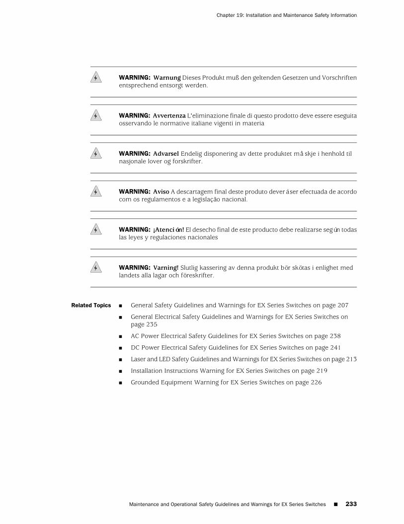
WARNING: Warnung Dieses Produkt muß den geltenden Gesetzen und Vorschriftenentsprechend entsorgt werden.
WARNING: Avvertenza L'eliminazione finale di questo prodotto deve essere eseguitaosservando le normative italiane vigenti in materia
WARNING: Advarsel Endelig disponering av dette produktet må skje i henhold tilnasjonale lover og forskrifter.
WARNING: Aviso A descartagem final deste produto deverá ser efectuada de acordocom os regulamentos e a legislação nacional.
WARNING: ¡Atención! El desecho final de este producto debe realizarse según todaslas leyes y regulaciones nacionales
WARNING: Varning! Slutlig kassering av denna produkt bör skötas i enlighet medlandets alla lagar och föreskrifter.
Related Topics ■ General Safety Guidelines and Warnings for EX Series Switches on page 207
■ General Electrical Safety Guidelines and Warnings for EX Series Switches onpage 235
■ AC Power Electrical Safety Guidelines for EX Series Switches on page 238
■ DC Power Electrical Safety Guidelines for EX Series Switches on page 241
■ Laser and LED Safety Guidelines and Warnings for EX Series Switches on page 213
■ Installation Instructions Warning for EX Series Switches on page 219
■ Grounded Equipment Warning for EX Series Switches on page 226
Maintenance and Operational Safety Guidelines and Warnings for EX Series Switches ■ 233
Chapter 19: Installation and Maintenance Safety Information

234 ■ Maintenance and Operational Safety Guidelines and Warnings for EX Series Switches
Complete Hardware Guide for EX3200 and EX4200 Ethernet Switches

Chapter 20
Power and Electrical Safety Information
■ General Electrical Safety Guidelines and Warnings for EX SeriesSwitches on page 235
■ Prevention of Electrostatic Discharge Damage on EX Series Switches on page 236
■ AC Power Electrical Safety Guidelines for EX Series Switches on page 238
■ AC Power Disconnection Warning for EX Series Switches on page 239
■ Multiple Power Supplies Disconnection Warning for EX SeriesSwitches on page 240
■ Power Sources for Redundant Power Supplies Warning for EX4200Switches on page 240
■ DC Power Electrical Safety Guidelines for EX Series Switches on page 241
■ DC Power Disconnection Warning for EX Series Switches on page 242
■ DC Power Grounding Requirements and Warning for EX SeriesSwitches on page 244
■ DC Power Wiring Sequence Warning for EX Series Switches on page 245
■ DC Power Wiring Terminations Warning for EX Series Switches on page 246
■ TN Power Warning for EX Series Switches on page 247
■ In Case of Electrical Accident: Action to Take on an EX Series Switch on page 248
General Electrical Safety Guidelines and Warnings for EX Series Switches
WARNING: Certain ports on the switch are designed for use as intrabuilding(within-the-building) interfaces only (Type 2 or Type 4 ports as described inGR-1089-CORE, Issue 4) and require isolation from the exposed outside plant (OSP)cabling. To comply with NEBS requirements and protect against lightning surges andcommercial power disturbances, the intrabuilding ports must not be metallicallyconnected to interfaces that connect to the OSP or its wiring. The intrabuilding portson the switch are suitable for connection to intrabuilding or unexposed wiring orcabling only. The addition of primary protectors is not sufficient protection forconnecting these interfaces metallically to OSP wiring.
General Electrical Safety Guidelines and Warnings for EX Series Switches ■ 235
CAUTION: Before removing or installing components of a switch, attach an ESDstrap to an ESD point and place the other end of the strap around your bare wrist.Failure to use an ESD strap could result in damage to the switch.
■ Install the EX Series switch in compliance with the following local, national, andinternational electrical codes:
■ United States—National Fire Protection Association (NFPA 70), United StatesNational Electrical Code.
■ Other countries—International Electromechanical Commission (IEC) 60364,Part 1 through Part 7.
■ Evaluated to the TN power system.
■ Canada—Canadian Electrical Code, Part 1, CSA C22.1.
■ Locate the emergency power-off switch for the room in which you are workingso that if an electrical accident occurs, you can quickly turn off the power.
■ Make sure that grounding surfaces are cleaned and brought to a bright finishbefore grounding connections are made.
■ Do not work alone if potentially hazardous conditions exist anywhere in yourworkspace.
■ Never assume that power is disconnected from a circuit. Always check the circuitbefore starting to work.
■ Carefully look for possible hazards in your work area, such as moist floors,ungrounded power extension cords, and missing safety grounds.
■ Operate the EX Series switch within marked electrical ratings and product usageinstructions.
■ To ensure that the EX Series switch and peripheral equipment function safelyand correctly, use the cables and connectors specified for the attached peripheralequipment, and make certain they are in good condition.
You can remove and replace many switch components without powering off ordisconnecting power to the switch, as detailed elsewhere in the hardwaredocumentation for this product. Never install equipment if it appears damaged.
Related Topics General Safety Guidelines and Warnings for EX Series Switches on page 207■
■ AC Power Electrical Safety Guidelines for EX Series Switches on page 238
■ DC Power Electrical Safety Guidelines for EX Series Switches on page 241
Prevention of Electrostatic Discharge Damage on EX Series Switches
Switch components that are shipped in antistatic bags are sensitive to damage fromstatic electricity. Some components can be impaired by voltages as low as 30 V. Youcan easily generate potentially damaging static voltages whenever you handle plastic
236 ■ Prevention of Electrostatic Discharge Damage on EX Series Switches
Complete Hardware Guide for EX3200 and EX4200 Ethernet Switches
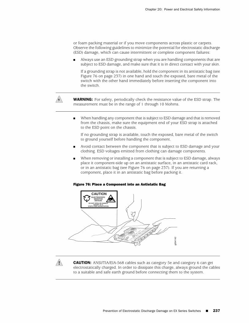
or foam packing material or if you move components across plastic or carpets.Observe the following guidelines to minimize the potential for electrostatic discharge(ESD) damage, which can cause intermittent or complete component failures:
■ Always use an ESD grounding strap when you are handling components that aresubject to ESD damage, and make sure that it is in direct contact with your skin.
If a grounding strap is not available, hold the component in its antistatic bag (seeFigure 76 on page 237) in one hand and touch the exposed, bare metal of theswitch with the other hand immediately before inserting the component intothe switch.
WARNING: For safety, periodically check the resistance value of the ESD strap. Themeasurement must be in the range of 1 through 10 Mohms.
■ When handling any component that is subject to ESD damage and that is removedfrom the chassis, make sure the equipment end of your ESD strap is attachedto the ESD point on the chassis.
If no grounding strap is available, touch the exposed, bare metal of the switchto ground yourself before handling the component.
■ Avoid contact between the component that is subject to ESD damage and yourclothing. ESD voltages emitted from clothing can damage components.
■ When removing or installing a component that is subject to ESD damage, alwaysplace it component-side up on an antistatic surface, in an antistatic card rack,or in an antistatic bag (see Figure 76 on page 237). If you are returning acomponent, place it in an antistatic bag before packing it.
Figure 76: Place a Component into an Antistatic Bag
CAUTION: ANSI/TIA/EIA-568 cables such as category 5e and category 6 can getelectrostatically charged. In order to dissipate this charge, always ground the cablesto a suitable and safe earth ground before connecting them to the system.
Prevention of Electrostatic Discharge Damage on EX Series Switches ■ 237
Chapter 20: Power and Electrical Safety Information

Related Topics ■ General Safety Guidelines and Warnings for EX Series Switches on page 207
■ See Rear Panel of an EX2200 Switch for the ESD point location.
■ See Rear Panel of an EX3200 Switch on page 9 for the ESD point location.
■ See Rear Panel of an EX4200 Switch on page 11 for the ESD point location.
■ See Chassis Physical Specifications of an EX8208 Switch for the ESD pointlocation.
■ See Chassis Physical Specifications of an EX8216 Switch for the ESD pointlocation.
AC Power Electrical Safety Guidelines for EX Series Switches
CAUTION: For switches with AC power supplies, an external surge protective device(SPD) must be used at the AC power source.
The following electrical safety guidelines apply to AC-powered switches:
■ AC-powered switches are shipped with a three-wire electrical cord with agrounding-type plug that fits only a grounding-type power outlet. Do notcircumvent this safety feature. Equipment grounding must comply with localand national electrical codes.
■ You must provide an external certified circuit breaker rated minimum 20 A inthe building installation.
■ The power cord serves as the main disconnecting device for the switch. Thesocket outlet must be near the switch and be easily accessible.
■ For EX Series switches that have more than one power supply connection, youmust ensure that all power connections are fully disconnected so that power tothe switch is completely removed to avoid electric shock. To disconnect power,unplug all power cords (one for each power supply).
■ Note the following warnings printed on the label next to the power supplies:
“CAUTION: THIS UNIT HAS MORE THAN ONE POWER SUPPLY CORD.DISCONNECT ALL POWER SUPPLY CORDS BEFORE SERVICING TO AVOIDELECTRIC SHOCK.”
238 ■ AC Power Electrical Safety Guidelines for EX Series Switches
Complete Hardware Guide for EX3200 and EX4200 Ethernet Switches
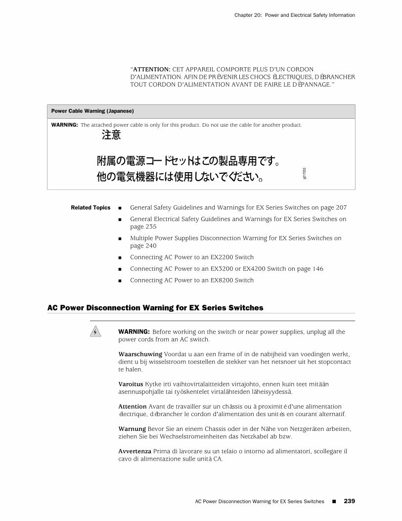
“ATTENTION: CET APPAREIL COMPORTE PLUS D'UN CORDOND'ALIMENTATION. AFIN DE PRÉVENIR LES CHOCS ÉLECTRIQUES, DÉBRANCHERTOUT CORDON D'ALIMENTATION AVANT DE FAIRE LE DÉPANNAGE.”
Power Cable Warning (Japanese)
WARNING: The attached power cable is only for this product. Do not use the cable for another product.
Related Topics ■ General Safety Guidelines and Warnings for EX Series Switches on page 207
■ General Electrical Safety Guidelines and Warnings for EX Series Switches onpage 235
■ Multiple Power Supplies Disconnection Warning for EX Series Switches onpage 240
■ Connecting AC Power to an EX2200 Switch
■ Connecting AC Power to an EX3200 or EX4200 Switch on page 146
■ Connecting AC Power to an EX8200 Switch
AC Power Disconnection Warning for EX Series Switches
WARNING: Before working on the switch or near power supplies, unplug all thepower cords from an AC switch.
Waarschuwing Voordat u aan een frame of in de nabijheid van voedingen werkt,dient u bij wisselstroom toestellen de stekker van het netsnoer uit het stopcontactte halen.
Varoitus Kytke irti vaihtovirtalaitteiden virtajohto, ennen kuin teet mitäänasennuspohjalle tai työskentelet virtalähteiden läheisyydessä.
Attention Avant de travailler sur un châssis ou à proximité d'une alimentationélectrique, débrancher le cordon d'alimentation des unités en courant alternatif.
Warnung Bevor Sie an einem Chassis oder in der Nähe von Netzgeräten arbeiten,ziehen Sie bei Wechselstromeinheiten das Netzkabel ab bzw.
Avvertenza Prima di lavorare su un telaio o intorno ad alimentatori, scollegare ilcavo di alimentazione sulle unità CA.
AC Power Disconnection Warning for EX Series Switches ■ 239
Chapter 20: Power and Electrical Safety Information
Advarsel Før det utføres arbeid på kabinettet eller det arbeides i nærheten avstrømforsyningsenheter, skal strømledningen trekkes ut på vekselstrømsenheter.
Aviso Antes de trabalhar num chassis, ou antes de trabalhar perto de unidades defornecimento de energia, desligue o cabo de alimentação nas unidades de correntealternada.
¡Atención! Antes de manipular el chasis de un equipo o trabajar cerca de una fuentede alimentación, desenchufar el cable de alimentación en los equipos de corrientealterna (CA).
Varning! Innan du arbetar med ett chassi eller nära strömförsörjningsenheter skalldu för växelströmsenheter dra ur nätsladden.
Related Topics General Safety Guidelines and Warnings for EX Series Switches on page 207■
■ General Electrical Safety Guidelines and Warnings for EX Series Switches onpage 235
■ AC Power Electrical Safety Guidelines for EX Series Switches on page 238
Multiple Power Supplies Disconnection Warning for EX Series Switches
WARNING: For EX Series switches that have more than one power supply connection,you must ensure that all power connections are fully disconnected so that power tothe switch is completely removed.
Related Topics ■ General Safety Guidelines and Warnings for EX Series Switches on page 207
■ General Electrical Safety Guidelines and Warnings for EX Series Switches onpage 235
■ AC Power Electrical Safety Guidelines for EX Series Switches on page 238
■ DC Power Electrical Safety Guidelines for EX Series Switches on page 241
Power Sources for Redundant Power Supplies Warning for EX4200 Switches
EX4200 switches have a redundant power supply. When you have redundant powersupplies in a switch, you must connect each power supply to a different input powersource. Failure to do so makes the switch susceptible to total power failure if one ofthe power supplies fails.
240 ■ Multiple Power Supplies Disconnection Warning for EX Series Switches
Complete Hardware Guide for EX3200 and EX4200 Ethernet Switches

Related Topics General Safety Guidelines and Warnings for EX Series Switches on page 207■
■ General Electrical Safety Guidelines and Warnings for EX Series Switches onpage 235
■ AC Power Electrical Safety Guidelines for EX Series Switches on page 238
DC Power Electrical Safety Guidelines for EX Series Switches
The following electrical safety guidelines apply to a DC-powered switch:
■ A DC-powered switch is equipped with a DC terminal block that is rated for thepower requirements of a maximally configured switch.
NOTE: To supply sufficient power, terminate the DC input wiring on a facility DCsource capable of supplying at least 8 A at –48 VDC for EX3200 and EX4200 switches.
To supply sufficient power, terminate the DC input wiring on a facility DC sourcecapable of supplying at least 60 A at –48 VDC for EX8208 switches.
To supply sufficient power, terminate the DC input wiring on a facility DC sourcecapable of supplying at least 100 A at –48 VDC for EX8216 switches.
Incorporate an easily accessible disconnect device into the facility wiring. Besure to connect the ground wire or conduit to a solid office earth ground. A closedloop ring is recommended for terminating the ground conductor at the groundstud.
■ Run two wires from the circuit breaker box to a source of 48 VDC.
■ A DC-powered router that is equipped with a DC terminal block is intended onlyfor installation in a restricted access location. In the United States, a restrictedaccess area is one in accordance with Articles 110-16, 110-17, and 110-18 ofthe National Electrical Code ANSI/NFPA 70.
NOTE: Primary overcurrent protection is provided by the building circuit breaker.This breaker must protect against excess currents, short circuits, and earth groundingfaults in accordance with NEC ANSI/NFPA 70.
■ Ensure that the polarity of the DC input wiring is correct. Under certain conditions,connections with reversed polarity might trip the primary circuit breaker ordamage the equipment.
DC Power Electrical Safety Guidelines for EX Series Switches ■ 241
Chapter 20: Power and Electrical Safety Information
■ For personal safety, connect the green and yellow wire to safety (earth) groundat both the switch and the supply side of the DC wiring.
■ The marked input voltage of –48 VDC for a DC-powered switch is the nominalvoltage associated with the battery circuit, and any higher voltages are only tobe associated with float voltages for the charging function.
■ Because the switch is a positive ground system, you must connect the positivelead to the terminal labeled RTN, the negative lead to the terminal labeled–48 VDC, and the earth ground to the chassis grounding points.
Related Topics ■ General Safety Guidelines and Warnings for EX Series Switches on page 207
■ General Electrical Safety Guidelines and Warnings for EX Series Switches onpage 235
■ DC Power Disconnection Warning for EX Series Switches on page 242
■ DC Power Grounding Requirements and Warning for EX Series Switches onpage 244
■ DC Power Wiring Sequence Warning for EX Series Switches on page 245
■ DC Power Wiring Terminations Warning for EX Series Switches on page 246
■ Connecting DC Power to an EX3200 or EX4200 Switch on page 148
■ Connecting DC Power to an EX8200 Switch
DC Power Disconnection Warning for EX Series Switches
WARNING: Before performing any of the DC power procedures, ensure that poweris removed from the DC circuit. To ensure that all power is off, locate the circuitbreaker on the panel board that services the DC circuit, switch the circuit breaker tothe OFF position, and tape the switch handle of the circuit breaker in the OFF position.
Waarschuwing Voordat u een van de onderstaande procedures uitvoert, dient u tecontroleren of de stroom naar het gelijkstroom circuit uitgeschakeld is. Om u ervante verzekeren dat alle stroom UIT is geschakeld, kiest u op het schakelbord destroomverbreker die het gelijkstroom circuit bedient, draait de stroomverbreker naarde UIT positie en plakt de schakelaarhendel van de stroomverbreker met plakbandin de UIT positie vast.
Varoitus Varmista, että tasavirtapiirissä ei ole virtaa ennen seuraavien toimenpiteidensuorittamista. Varmistaaksesi, että virta on KATKAISTU täysin, paikanna tasavirrastahuolehtivassa kojetaulussa sijaitseva suojakytkin, käännä suojakytkinKATKAISTU-asentoon ja teippaa suojakytkimen varsi niin, että se pysyyKATKAISTU-asennossa.
Attention Avant de pratiquer l'une quelconque des procédures ci-dessous, vérifierque le circuit en courant continu n'est plus sous tension. Pour en être sûr, localiserle disjoncteur situé sur le panneau de service du circuit en courant continu, placer
242 ■ DC Power Disconnection Warning for EX Series Switches
Complete Hardware Guide for EX3200 and EX4200 Ethernet Switches
le disjoncteur en position fermée (OFF) et, à l'aide d'un ruban adhésif, bloquer lapoignée du disjoncteur en position OFF.
Warnung Vor Ausführung der folgenden Vorgänge ist sicherzustellen, daß dieGleichstromschaltung keinen Strom erhält. Um sicherzustellen, daß sämtlicher Stromabgestellt ist, machen Sie auf der Schalttafel den Unterbrecher für dieGleichstromschaltung ausfindig, stellen Sie den Unterbrecher auf AUS, und klebenSie den Schaltergriff des Unterbrechers mit Klebeband in der AUS-Stellung fest.
Avvertenza Prima di svolgere una qualsiasi delle procedure seguenti, verificare cheil circuito CC non sia alimentato. Per verificare che tutta l'alimentazione sia scollegata(OFF), individuare l'interruttore automatico sul quadro strumenti che alimenta ilcircuito CC, mettere l'interruttore in posizione OFF e fissarlo con nastro adesivo intale posizione.
Advarsel Før noen av disse prosedyrene utføres, kontroller at strømmen er frakobletlikestrømkretsen. Sørg for at all strøm er slått AV. Dette gjøres ved å lokaliserestrømbryteren på brytertavlen som betjener likestrømkretsen, slå strømbryteren AVog teipe bryterhåndtaket på strømbryteren i AV-stilling.
Aviso Antes de executar um dos seguintes procedimentos, certifique-se que desligoua fonte de alimentação de energia do circuito de corrente contínua. Para se assegurarque toda a corrente foi DESLIGADA, localize o disjuntor no painel que serve o circuitode corrente contínua e coloque-o na posição OFF (Desligado), segurando nessaposição a manivela do interruptor do disjuntor com fita isoladora.
¡Atención! Antes de proceder con los siguientes pasos, comprobar que la alimentacióndel circuito de corriente continua (CC) esté cortada (OFF). Para asegurarse de quetoda la alimentación esté cortada (OFF), localizar el interruptor automático en elpanel que alimenta al circuito de corriente continua, cambiar el interruptor automáticoa la posición de Apagado (OFF), y sujetar con cinta la palanca del interruptorautomático en posición de Apagado (OFF).
Varning! Innan du utför någon av följande procedurer måste du kontrollera attströmförsörjningen till likströmskretsen är bruten. Kontrollera att all strömförsörjningär BRUTEN genom att slå AV det överspänningsskydd som skyddar likströmskretsenoch tejpa fast överspänningsskyddets omkopplare i FRÅN-läget.
Related Topics ■ General Safety Guidelines and Warnings for EX Series Switches on page 207
■ General Electrical Safety Guidelines and Warnings for EX Series Switches onpage 235
■ DC Power Electrical Safety Guidelines for EX Series Switches on page 241
■ DC Power Grounding Requirements and Warning for EX Series Switches onpage 244
■ DC Power Wiring Sequence Warning for EX Series Switches on page 245
■ DC Power Wiring Terminations Warning for EX Series Switches on page 246
DC Power Disconnection Warning for EX Series Switches ■ 243
Chapter 20: Power and Electrical Safety Information
DC Power Grounding Requirements and Warning for EX Series Switches
An insulated grounding conductor that is identical in size to the grounded andungrounded branch circuit supply conductors but is identifiable by green and yellowstripes is installed as part of the branch circuit that supplies the unit. The groundingconductor is a separately derived system at the supply transformer or motor generatorset.
WARNING: When you install the switch, the ground connection must always bemade first and disconnected last.
Waarschuwing Bij de installatie van het toestel moet de aardverbinding altijd heteerste worden gemaakt en het laatste worden losgemaakt.
Varoitus Laitetta asennettaessa on maahan yhdistäminen aina tehtävä ensiksi jamaadoituksen irti kytkeminen viimeiseksi.
Attention Lors de l'installation de l'appareil, la mise à la terre doit toujours êtreconnectée en premier et déconnectée en dernier.
Warnung Der Erdanschluß muß bei der Installation der Einheit immer zuersthergestellt und zuletzt abgetrennt werden.
Avvertenza In fase di installazione dell'unità, eseguire sempre per primo ilcollegamento a massa e disconnetterlo per ultimo.
Advarsel Når enheten installeres, må jordledningen alltid tilkobles først og frakoblessist.
Aviso Ao instalar a unidade, a ligação à terra deverá ser sempre a primeira a serligada, e a última a ser desligada.
¡Atención! Al instalar el equipo, conectar la tierra la primera y desconectarla la última.
Varning! Vid installation av enheten måste jordledningen alltid anslutas först ochkopplas bort sist.
Related Topics ■ General Safety Guidelines and Warnings for EX Series Switches on page 207
■ General Electrical Safety Guidelines and Warnings for EX Series Switches onpage 235
■ DC Power Electrical Safety Guidelines for EX Series Switches on page 241
■ DC Power Disconnection Warning for EX Series Switches on page 242
■ DC Power Wiring Sequence Warning for EX Series Switches on page 245
■ DC Power Wiring Terminations Warning for EX Series Switches on page 246
244 ■ DC Power Grounding Requirements and Warning for EX Series Switches
Complete Hardware Guide for EX3200 and EX4200 Ethernet Switches
DC Power Wiring Sequence Warning for EX Series Switches
WARNING: Wire the DC power supply using the appropriate lugs. When connectingpower, the proper wiring sequence is ground to ground, +RTN to +RTN, then –48 Vto –48 V. When disconnecting power, the proper wiring sequence is –48 V to –48 V,+RTN to +RTN, then ground to ground. Note that the ground wire must always beconnected first and disconnected last.
Waarschuwing De juiste bedradingsvolgorde verbonden is aarde naar aarde, +RTNnaar +RTN, en –48 V naar – 48 V. De juiste bedradingsvolgorde losgemaakt is en–48 naar –48 V, +RTN naar +RTN, aarde naar aarde.
Varoitus Oikea yhdistettava kytkentajarjestys on maajohto maajohtoon, +RTN varten+RTN, –48 V varten – 48 V. Oikea irrotettava kytkentajarjestys on –48 V varten –48 V, +RTN varten +RTN, maajohto maajohtoon.
Attention Câblez l'approvisionnement d'alimentation CC En utilisant les crochetsappropriés à l'extrémité de câblage. En reliant la puissance, l'ordre approprié decâblage est rectifié pour rectifier, +RTN à +RTN, puis –48 V à –48 V. En débranchantla puissance, l'ordre approprié de câblage est –48 V à –48 V, +RTN à +RTN, a alorsrectifié pour rectifier. Notez que le fil de masse devrait toujours être relié d'abord etdébranché pour la dernière fois. Notez que le fil de masse devrait toujours être reliéd'abord et débranché pour la dernière fois.
Warnung Die Stromzufuhr ist nur mit geeigneten Ringösen an das DC Netzteilanzuschliessen. Die richtige Anschlusssequenz ist: Erdanschluss zu Erdanschluss,+RTN zu +RTN und dann -48V zu -48V. Die richtige Sequenz zum Abtrennen derStromversorgung ist -48V zu -48V, +RTN zu +RTN und dann Erdanschluss zuErdanschluss. Es ist zu beachten dass der Erdanschluss immer zuerst angeschlossenund als letztes abgetrennt wird.
Avvertenza Mostra la morsettiera dell alimentatore CC. Cablare l'alimentatore CCusando i connettori adatti all'estremità del cablaggio, come illustrato. La correttasequenza di cablaggio è da massa a massa, da positivo a positivo (da linea ad L) eda negativo a negativo (da neutro a N). Tenere presente che il filo di massa devesempre venire collegato per primo e scollegato per ultimo.
Advarsel Riktig tilkoples tilkoplingssekvens er jord til jord, +RTN til +RTN, –48 Vtil – 48 V. Riktig frakoples tilkoplingssekvens er –48 V til – 48 V, +RTN til +RTN,jord til jord.
Aviso Ate con alambre la fuente de potencia cc Usando los terminales apropiadosen el extremo del cableado. Al conectar potencia, la secuencia apropiada del cableadose muele para moler, +RTN a +RTN, entonces –48 V a –48 V. Al desconectarpotencia, la secuencia apropiada del cableado es –48 V a –48 V, +RTN a +RTN,entonces molió para moler. Observe que el alambre de tierra se debe conectarsiempre primero y desconectar por último. Observe que el alambre de tierra se debeconectar siempre primero y desconectar por último.
DC Power Wiring Sequence Warning for EX Series Switches ■ 245
Chapter 20: Power and Electrical Safety Information
¡Atención! Wire a fonte de alimentação de DC Usando os talões apropriados naextremidade da fiação. Ao conectar a potência, a seqüência apropriada da fiação émoída para moer, +RTN a +RTN, então –48 V a –48 V. Ao desconectar a potência,a seqüência apropriada da fiação é –48 V a –48 V, +RTN a +RTN, moeu então paramoer. Anote que o fio à terra deve sempre ser conectado primeiramente edesconectado por último. Anote que o fio à terra deve sempre ser conectadoprimeiramente e desconectado por último.
Varning! Korrekt kopplingssekvens ar jord till jord, +RTN till +RTN, –48 V till –48 V.Korrekt kopplas kopplingssekvens ar –48 V till –48 V, +RTN till +RTN, jord till jord.
Related Topics ■ General Safety Guidelines and Warnings for EX Series Switches on page 207
■ General Electrical Safety Guidelines and Warnings for EX Series Switches onpage 235
■ DC Power Electrical Safety Guidelines for EX Series Switches on page 241
■ DC Power Disconnection Warning for EX Series Switches on page 242
■ DC Power Grounding Requirements and Warning for EX Series Switches onpage 244
■ DC Power Wiring Terminations Warning for EX Series Switches on page 246
DC Power Wiring Terminations Warning for EX Series Switches
WARNING: When stranded wiring is required, use approved wiring terminations,such as closed-loop or spade-type with upturned lugs. These terminations must bethe appropriate size for the wires and must clamp both the insulation and conductor.
Waarschuwing Wanneer geslagen bedrading vereist is, dient u bedrading te gebruikendie voorzien is van goedgekeurde aansluitingspunten, zoals het gesloten-lus type ofhet grijperschop type waarbij de aansluitpunten omhoog wijzen. Deze aansluitpuntendienen de juiste maat voor de draden te hebben en dienen zowel de isolatie als degeleider vast te klemmen.
Varoitus Jos säikeellinen johdin on tarpeen, käytä hyväksyttyä johdinliitäntää,esimerkiksi suljettua silmukkaa tai kourumaista liitäntää, jossa on ylöspäin käännetytkiinnityskorvat. Tällaisten liitäntöjen tulee olla kooltaan johtimiin sopivia ja niidentulee puristaa yhteen sekä eristeen että johdinosan.
Attention Quand des fils torsadés sont nécessaires, utiliser des douilles terminaleshomologuées telles que celles à circuit fermé ou du type à plage ouverte avec cossesrebroussées. Ces douilles terminales doivent être de la taille qui convient aux fils etdoivent être refermées sur la gaine isolante et sur le conducteur.
Warnung Wenn Litzenverdrahtung erforderlich ist, sind zugelasseneVerdrahtungsabschlüsse, z.B. für einen geschlossenen Regelkreis oder gabelförmig,
246 ■ DC Power Wiring Terminations Warning for EX Series Switches
Complete Hardware Guide for EX3200 and EX4200 Ethernet Switches
mit nach oben gerichteten Kabelschuhen zu verwenden. Diese Abschlüsse solltendie angemessene Größe für die Drähte haben und sowohl die Isolierung als auch denLeiter festklemmen.
Avvertenza Quando occorre usare trecce, usare connettori omologati, come quellia occhiello o a forcella con linguette rivolte verso l'alto. I connettori devono avere lamisura adatta per il cablaggio e devono serrare sia l'isolante che il conduttore.
Advarsel Hvis det er nødvendig med flertrådede ledninger, brukes godkjenteledningsavslutninger, som for eksempel lukket sløyfe eller spadetype medoppoverbøyde kabelsko. Disse avslutningene skal ha riktig størrelse i forhold tilledningene, og skal klemme sammen både isolasjonen og lederen.
Aviso Quando forem requeridas montagens de instalação eléctrica de cabo torcido,use terminações de cabo aprovadas, tais como, terminações de cabo em circuitofechado e planas com terminais de orelha voltados para cima. Estas terminações decabo deverão ser do tamanho apropriado para os respectivos cabos, e deverãoprender simultaneamente o isolamento e o fio condutor.
¡Atención! Cuando se necesite hilo trenzado, utilizar terminales para cableshomologados, tales como las de tipo "bucle cerrado" o "espada", con las lengüetasde conexión vueltas hacia arriba. Estos terminales deberán ser del tamaño apropiadopara los cables que se utilicen, y tendrán que sujetar tanto el aislante como elconductor.
Varning! När flertrådiga ledningar krävs måste godkända ledningskontakter användas,t.ex. kabelsko av sluten eller öppen typ med uppåtvänd tapp. Storleken på dessakontakter måste vara avpassad till ledningarna och måste kunna hålla både isoleringenoch ledaren fastklämda.
Related Topics ■ General Safety Guidelines and Warnings for EX Series Switches on page 207
■ General Electrical Safety Guidelines and Warnings for EX Series Switches onpage 235
■ DC Power Electrical Safety Guidelines for EX Series Switches on page 241
■ DC Power Disconnection Warning for EX Series Switches on page 242
■ DC Power Grounding Requirements and Warning for EX Series Switches onpage 244
■ DC Power Wiring Sequence Warning for EX Series Switches on page 245
TN Power Warning for EX Series Switches
WARNING: The switch is designed to work with a TN power system.
TN Power Warning for EX Series Switches ■ 247
Chapter 20: Power and Electrical Safety Information
Waarschuwing Het apparaat is ontworpen om te functioneren met TNenergiesystemen.
Varoitus Koje on suunniteltu toimimaan TN-sähkövoimajärjestelmien yhteydessä.
Attention Ce dispositif a été conçu pour fonctionner avec des systèmes d'alimentationTN.
Warnung Das Gerät ist für die Verwendung mit TN-Stromsystemen ausgelegt.
Avvertenza Il dispositivo è stato progettato per l'uso con sistemi di alimentazioneTN.
Advarsel Utstyret er utfomet til bruk med TN-strømsystemer.
Aviso O dispositivo foi criado para operar com sistemas de corrente TN.
¡Atención! El equipo está diseñado para trabajar con sistemas de alimentación tipoTN.
Varning! Enheten är konstruerad för användning tillsammans med elkraftssystemav TN-typ.
Related Topics ■ General Safety Guidelines and Warnings for EX Series Switches on page 207
■ General Electrical Safety Guidelines and Warnings for EX Series Switches onpage 235
■ Grounded Equipment Warning for EX Series Switches on page 226
■ Multiple Power Supplies Disconnection Warning for EX Series Switches onpage 240
In Case of Electrical Accident: Action to Take on an EX Series Switch
If an electrical accident results in an injury, take the following actions in this order:
1. Use caution. Be aware of potentially hazardous conditions that could cause furtherinjury.
2. Disconnect power from the switch.
3. If possible, send another person to get medical aid. Otherwise, assess thecondition of the victim, then call for help.
Related Topics ■ General Safety Guidelines and Warnings for EX Series Switches on page 207
■ General Electrical Safety Guidelines and Warnings for EX Series Switches onpage 235
248 ■ In Case of Electrical Accident: Action to Take on an EX Series Switch
Complete Hardware Guide for EX3200 and EX4200 Ethernet Switches

■ AC Power Electrical Safety Guidelines for EX Series Switches on page 238
■ DC Power Electrical Safety Guidelines for EX Series Switches on page 241
In Case of Electrical Accident: Action to Take on an EX Series Switch ■ 249
Chapter 20: Power and Electrical Safety Information

250 ■ In Case of Electrical Accident: Action to Take on an EX Series Switch
Complete Hardware Guide for EX3200 and EX4200 Ethernet Switches

Part 9
Compliance Information
■ Compliance Information on page 253
Compliance Information ■ 251

252 ■ Compliance Information
Complete Hardware Guide for EX3200 and EX4200 Ethernet Switches

Chapter 21
Compliance Information
■ Agency Approvals for EX Series Switches on page 253
■ Compliance Statements for EMC Requirements for EX Series Switches on page 254
■ Compliance Statements for Acoustic Noise for EX Series Switches on page 256
Agency Approvals for EX Series Switches
EX Series switches comply with the following standards:
■ Safety
■ CAN/CSA-22.2 No. 60950–1–03/UL 60950–1. Safety of InformationTechnology Equipment
■ EN 60950–1:2001. Safety of Information Technology Equipment
■ EN 60825–1 Safety of Laser Products – Part 1: Equipment Classification,Requirements and User's Guide
■ EMC
■ FCC 47CFR Part 15 Class A (USA)
■ EN 55022 Class A Emissions (Europe)
■ ICES-003 Class A
■ VCCI Class A (Japan)
■ AS/NZS CISPR 22 Class A (Australia/New Zealand)
■ CISPR 22 Class A
■ EN 55024
■ EN 300386
■ EN 61000-3-2 Power Line Harmonics
■ EN 61000-3-3 Voltage Fluctuations and Flicker
■ EN 61000-4-2 ESD
■ EN 61000-4-3 Radiated Immunity
■ EN 61000-4-4 EFT
Agency Approvals for EX Series Switches ■ 253

■ EN 61000-4-5 Surge
■ EN 61000-4-6 Low Frequency Common Immunity
■ EN 61000-4-11 Voltage Dips and Sags
Related Topics Compliance Statements for EMC Requirements for EX Series Switches on page 254■
■ Compliance Statements for Acoustic Noise for EX Series Switches on page 256
Compliance Statements for EMC Requirements for EX Series Switches
This topic describes the EMC requirements for EX Series switches for:
■ Canada on page 254
■ European Community on page 255
■ Japan on page 255
■ United States on page 255
■ FCC Part 15 Statement on page 255
■ Non-Regulatory Environmental Standards on page 256
Canada
This Class A digital apparatus complies with Canadian ICES-003.
Cet appareil numérique de la classe A est conforme à la norme NMB-003 du Canada.
The Industry Canada label identifies certified equipment. This certification meansthat the equipment meets certain telecommunications network protective, operational,and safety requirements. Industry Canada does not guarantee the equipment willoperate to the users’ satisfaction.
Before installing this equipment, users should ensure that it is permissible to connectthe equipment to the facilities of the local telecommunications company. Theequipment must also be installed using an acceptable method of connection. In somecases, the inside wiring associated with a single line individual service may beextended by means of a certified connector assembly. The customer should be awarethat compliance with the above conditions may not prevent degradation of servicein some situations.
Repairs to certified equipment should be made by an authorized Canadianmaintenance facility designated by the supplier. Any repairs or alterations made bythe user to this equipment, or equipment malfunctions, may give thetelecommunications company cause to request the user to disconnect the equipment.
254 ■ Compliance Statements for EMC Requirements for EX Series Switches
Complete Hardware Guide for EX3200 and EX4200 Ethernet Switches

CAUTION: Users should not attempt to make electrical ground connections bythemselves, but should contact the appropriate inspection authority or an electrician,as appropriate.
Users should ensure for their own protection that the electrical ground connectionsof the power utility, telephone lines, and internal metallic water pipe system, ifpresent, are connected together. This precaution may be particularly important inrural areas.
European Community
This is a Class A product. In a domestic environment this product may cause radiointerference in which case the user may be required to take adequate measures.
Japan
The preceding translates as follows:
This is a Class A product. In a domestic environment this product may cause radiointerference in which case the user may be required to take adequate measures.
VCCI-A
United States
The EX Series switch has been tested and found to comply with the limits for a Class Adigital device, pursuant to Part 15 of the FCC Rules. These limits are designed toprovide reasonable protection against harmful interference when the equipment isoperated in a commercial environment. This equipment generates, uses, and canradiate radio frequency energy and, if not installed and used in accordance with theinstruction manual, may cause harmful interference to radio communications.Operation of this equipment in a residential area is likely to cause harmful interferencein which case the user will be required to correct the interference at his own expense.
FCC Part 15 Statement
This equipment has been tested and found to comply with the limits for a Class Adigital device pursuant to Part 15 of the FCC Rules. These limits are designed toprovide reasonable protection against harmful interference in a residential installation.This equipment generates, uses, and can radiate radio frequency energy and, if notinstalled and used in accordance with the instructions, may cause harmful interferenceto radio communications. However, there is no guarantee that interference will notoccur in a particular installation.
Compliance Statements for EMC Requirements for EX Series Switches ■ 255
Chapter 21: Compliance Information
If this equipment does cause harmful interference to radio or television reception,which can be determined by turning the equipment off and on, the user is encouragedto try and correct the interference by one or more of the following measures:
■ Reorient or relocate the receiving antenna.
■ Increase the separation between the equipment and the receiver.
■ Connect the equipment into an outlet on a circuit different from that to whichthe receiver is connected.
■ Consult the dealer or an experienced radio or TV technician for help.
Non-Regulatory Environmental Standards
NEBS compliance—These EX Series switch models are Network Equipment BuildingSystem (NEBS) compliant:
■ EX2200-24T and EX2200-48T
■ EX3200-24T, EX3200-48T, EX4200-24F, EX4200-24T, and EX4200-48T
■ All EX8200 models
Those switch models meet the following NEBS compliance standards:
■ SR-3580 NEBS Criteria Levels (Level 3 Compliance)
■ GR-1089-CORE: EMC and Electrical Safety for Network TelecommunicationsEquipment
■ GR-63-CORE: NEBS, Physical Protection
■ The equipment is suitable for installation as part of the Common BondingNetwork (CBN).
■ The equipment is suitable for installation in locations where the NationalElectrical Code (NEC) applies.
■ The battery return connection is to be treated as an Isolated DC return (DC-I),as defined in GR-1089-CORE.
Related Topics Agency Approvals for EX Series Switches on page 253■
■ Compliance Statements for Acoustic Noise for EX Series Switches on page 256
Compliance Statements for Acoustic Noise for EX Series Switches
Maschinenlärminformations-Verordnung - 3. GPSGV, der höchste Schalldruckpegelbeträgt 70 dB(A) oder weniger gemäss EN ISO 7779
Translation:
The emitted sound pressure is below 70 dB(A) per EN ISO 7779.
256 ■ Compliance Statements for Acoustic Noise for EX Series Switches
Complete Hardware Guide for EX3200 and EX4200 Ethernet Switches

Related Topics ■ Agency Approvals for EX Series Switches on page 253
■ Compliance Statements for EMC Requirements for EX Series Switches on page 254
Compliance Statements for Acoustic Noise for EX Series Switches ■ 257
Chapter 21: Compliance Information

258 ■ Compliance Statements for Acoustic Noise for EX Series Switches
Complete Hardware Guide for EX3200 and EX4200 Ethernet Switches