Embed Size (px)
Citation preview
This Compliance Document is prepared by the Department of Building and Housing. The Department of Building and Housing is a GovernmentDepartment established under the State Sector Act 1988.
Enquiries about the content of this document should be directed to:
Department of Building and HousingPO Box 10-729, Wellington.Telephone 0800 242 243Fax 04 494 0290 Email: [email protected]
Sales enquiries should be directed to:Customer Services,Victoria University Book CentrePO Box 12-337, Wellington, New ZealandTelephone 0800 370 370, (04) 463 5511Fax (04) 463 5510Email: [email protected] 0-477-01606-5
© Department of Building and Housing 2006
This Compliance Document is protected by Crown copyright, unless indicated otherwise.The Department of Building and Housing administers the copyright in this document. You may use and reproduce this document for your personal use or for the purposes of your business provided you reproduce the document accurately and not in an inappropriate or misleading context. You may not distribute this document to others or reproduce it for sale or profit.
The Department of Building and Housing owns or has licences to use all images andtrademarks in this document. You must not use or reproduce images and trademarks featured in this document for any purpose (except as part of an accurate reproduction of this document) unless you first obtain the written permission of the Department of Building and Housing.
Compliance Document for New Zealand Building Code Clause G10Piped ServicesPrepared by the Department of Building and Housing
ARCHIVED
Document Status
The most recent version of this document, as detailed in the Document History, is approved by the Chief Executive
of the Department of Building and Housing. It is effective from 23 June 2007 and supersedes all previous versions
of this document.
People using this Compliance Document should check for amendments on a regular basis. The Department of Building
and Housing may amend any part of any Compliance Document at any time. Up-to-date versions of Compliance
Documents are available from www.dbh.govt.nz
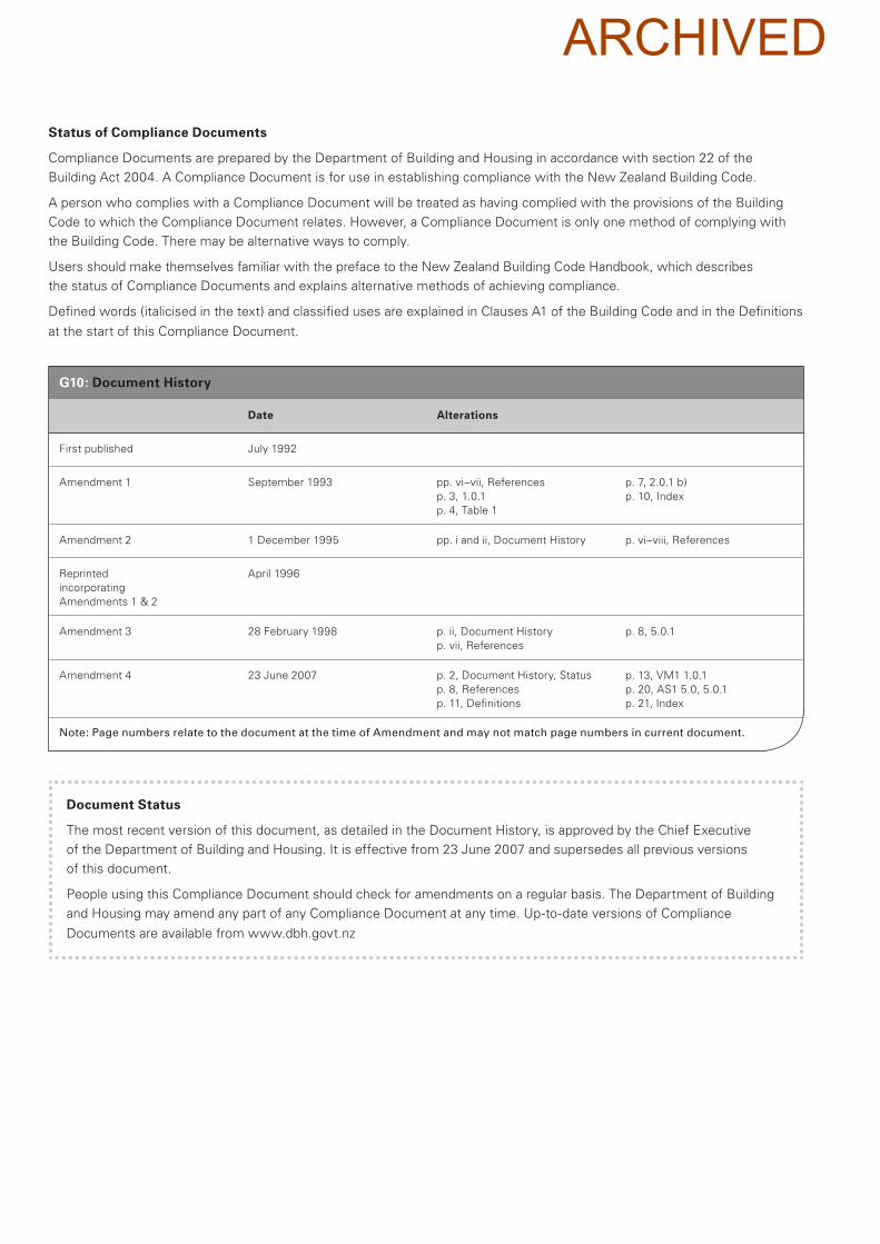
G10: Document History
Date Alterations
First published July 1992
Amendment 1 September 1993 pp. vi–vii, References
p. 3, 1.0.1
p. 4, Table 1
p. 7, 2.0.1 b)
p. 10, Index
Amendment 2 1 December 1995 pp. i and ii, Document History p. vi–viii, References
Reprinted
incorporating
Amendments 1 & 2
April 1996
Amendment 3 28 February 1998 p. ii, Document History
p. vii, References
p. 8, 5.0.1
Amendment 4 23 June 2007 p. 2, Document History, Status
p. 8, References
p. 11, Definitions
p. 13, VM1 1.0.1
p. 20, AS1 5.0, 5.0.1
p. 21, Index
Note: Page numbers relate to the document at the time of Amendment and may not match page numbers in current document.
Status of Compliance Documents
Compliance Documents are prepared by the Department of Building and Housing in accordance with section 22 of the
Building Act 2004. A Compliance Document is for use in establishing compliance with the New Zealand Building Code.
A person who complies with a Compliance Document will be treated as having complied with the provisions of the Building
Code to which the Compliance Document relates. However, a Compliance Document is only one method of complying with
the Building Code. There may be alternative ways to comply.
Users should make themselves familiar with the preface to the New Zealand Building Code Handbook, which describes
the status of Compliance Documents and explains alternative methods of achieving compliance.
Defined words (italicised in the text) and classified uses are explained in Clauses A1 of the Building Code and in the Definitions
at the start of this Compliance Document.
ARCHIVED
3
P I P E D S E R V I C E S
D E P A R T M E N T O F B U I L D I N G A N D H O U S I N G J u l y 1 9 9 2
Clause G10
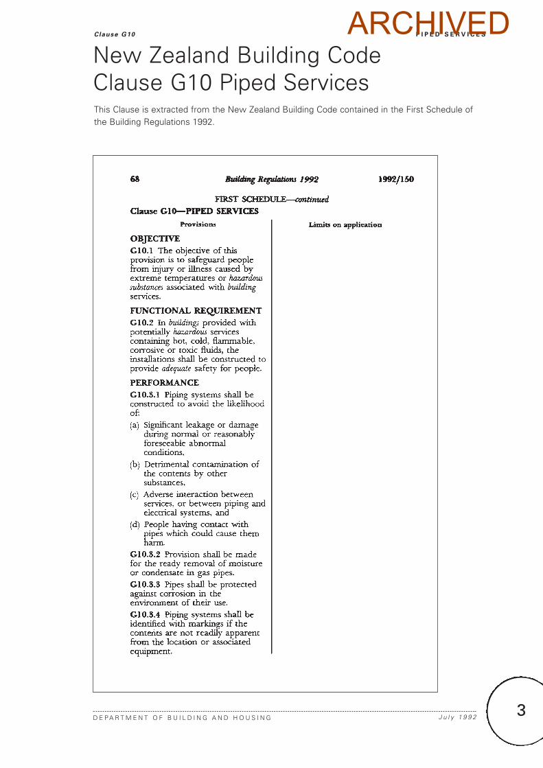
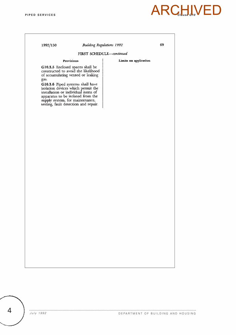
This Clause is extracted from the New Zealand Building Code contained in the First Schedule ofthe Building Regulations 1992.
New Zealand Building Code Clause G10 Piped Services
ARCHIVED
4
P I P E D S E R V I C E S Clause G10
D E P A R T M E N T O F B U I L D I N G A N D H O U S I N GJ u l y 1 9 9 2
ARCHIVED
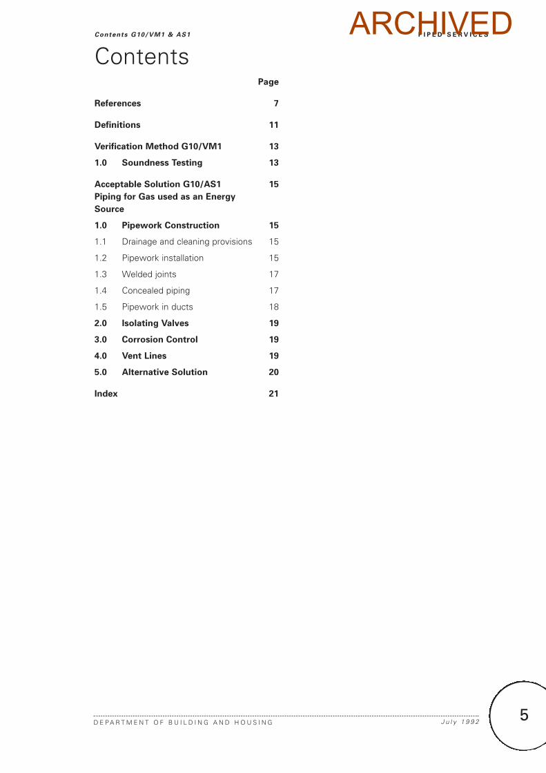
Page
References 7
Definitions 11
Verification Method G10/VM1 13
1.0 Soundness Testing 13
Acceptable Solution G10/AS1 15
Piping for Gas used as an Energy
Source
1.0 Pipework Construction 15
1.1 Drainage and cleaning provisions 15
1.2 Pipework installation 15
1.3 Welded joints 17
1.4 Concealed piping 17
1.5 Pipework in ducts 18
2.0 Isolating Valves 19
3.0 Corrosion Control 19
4.0 Vent Lines 19
5.0 Alternative Solution 20
Index 21
5
P I P E D S E R V I C E S
D E P A R T M E N T O F B U I L D I N G A N D H O U S I N G J u l y 1 9 9 2
Contents G10/VM1 & AS1
ContentsARCHIVED

6
ARCHIVED
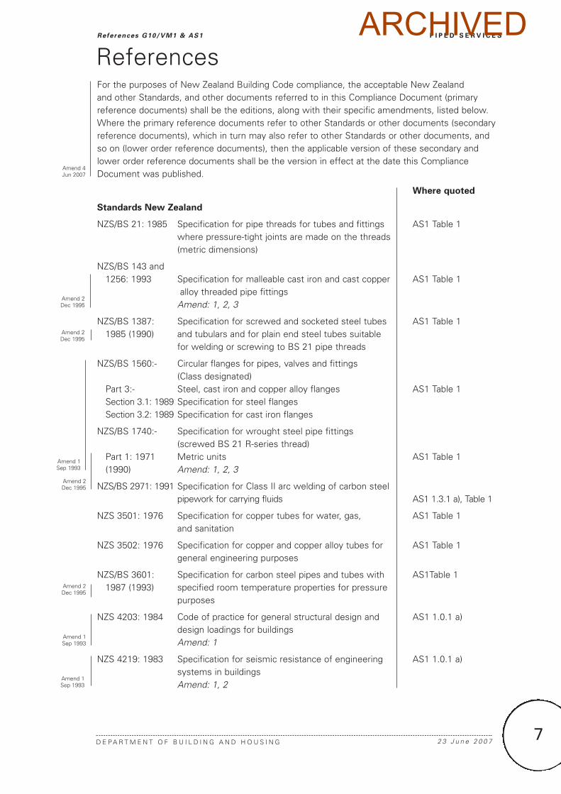
For the purposes of New Zealand Building Code compliance, the acceptable New Zealand and other Standards, and other documents referred to in this Compliance Document (primaryreference documents) shall be the editions, along with their specific amendments, listed below.Where the primary reference documents refer to other Standards or other documents (secondaryreference documents), which in turn may also refer to other Standards or other documents, andso on (lower order reference documents), then the applicable version of these secondary andlower order reference documents shall be the version in effect at the date this ComplianceDocument was published.
Where quoted
Standards New Zealand
NZS/BS 21: 1985 Specification for pipe threads for tubes and fittings AS1 Table 1where pressure-tight joints are made on the threads(metric dimensions)
NZS/BS 143 and1256: 1993 Specification for malleable cast iron and cast copper AS1 Table 1
alloy threaded pipe fittings Amend: 1, 2, 3
NZS/BS 1387: Specification for screwed and socketed steel tubes AS1 Table 11985 (1990) and tubulars and for plain end steel tubes suitable
for welding or screwing to BS 21 pipe threads
NZS/BS 1560:- Circular flanges for pipes, valves and fittings (Class designated)
Part 3:- Steel, cast iron and copper alloy flanges AS1 Table 1Section 3.1: 1989 Specification for steel flangesSection 3.2: 1989 Specification for cast iron flanges
NZS/BS 1740:- Specification for wrought steel pipe fittings (screwed BS 21 R-series thread)
Part 1: 1971 Metric units AS1 Table 1(1990) Amend: 1, 2, 3
NZS/BS 2971: 1991 Specification for Class II arc welding of carbon steel pipework for carrying fluids AS1 1.3.1 a), Table 1
NZS 3501: 1976 Specification for copper tubes for water, gas, AS1 Table 1and sanitation
NZS 3502: 1976 Specification for copper and copper alloy tubes for AS1 Table 1general engineering purposes
NZS/BS 3601: Specification for carbon steel pipes and tubes with AS1Table 11987 (1993) specified room temperature properties for pressure
purposes
NZS 4203: 1984 Code of practice for general structural design and AS1 1.0.1 a)design loadings for buildings Amend: 1
NZS 4219: 1983 Specification for seismic resistance of engineering AS1 1.0.1 a)systems in buildingsAmend: 1, 2
7
P I P E D S E R V I C E S
D E P A R T M E N T O F B U I L D I N G A N D H O U S I N G 2 3 J u n e 2 0 0 7
References G10/VM1 & AS1
References
Amend 4Jun 2007
Amend 2Dec 1995
Amend 2Dec 1995
Amend 1Sep 1993
Amend 2Dec 1995
Amend 2Dec 1995
Amend 1Sep 1993
Amend 1Sep 1993
ARCHIVED
Where quoted
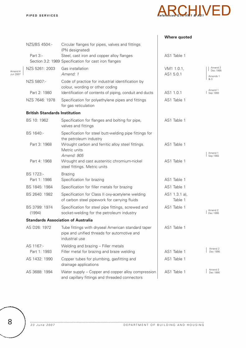
NZS/BS 4504:- Circular flanges for pipes, valves and fittings (PN designated)
Part 3:- Steel, cast iron and copper alloy flanges AS1 Table 1Section 3.2: 1989 Specification for cast iron flanges
NZS 5261: 2003 Gas installation VM1 1.0.1, Amend: 1 AS1 5.0.1
NZS 5807:- Code of practice for industrial identification by colour, wording or other coding
Part 2: 1980 Identification of contents of piping, conduit and ducts AS1 1.0.1
NZS 7646: 1978 Specification for polyethylene pipes and fittings AS1 Table 1for gas reticulation
British Standards Institution
BS 10: 1962 Specification for flanges and bolting for pipe, AS1 Table 1valves and fittings
BS 1640:- Specification for steel butt-welding pipe fittings for the petroleum industry
Part 3: 1968 Wrought carbon and ferritic alloy steel fittings. AS1 Table 1Metric units Amend: 905
Part 4: 1968 Wrought and cast austenitic chromium-nickel AS1 Table 1steel fittings. Metric units
BS 1723:- BrazingPart 1: 1986 Specification for brazing AS1 Table 1
BS 1845: 1984 Specification for filler metals for brazing AS1 Table 1
BS 2640: 1982 Specification for Class II oxy-acetylene welding AS1 1.3.1 a), of carbon steel pipework for carrying fluids Table 1
BS 3799: 1974 Specification for steel pipe fittings, screwed and AS1 Table 1(1994) socket-welding for the petroleum industry
Standards Association of Australia
AS D26: 1972 Tube fittings with dryseal American standard taper AS1 Table 1pipe and unified threads for automotive and industrial use
AS 1167:- Welding and brazing – Filler metalsPart 1: 1993 Filler metal for brazing and braze welding AS1 Table 1
AS 1432: 1990 Copper tubes for plumbing, gasfitting and AS1 Table 1drainage applications
AS 3688: 1994 Water supply – Copper and copper alloy compression AS1 Table 1and capillary fittings and threaded connectors
2 3 J u n e 2 0 0 7 D E P A R T M E N T O F B U I L D I N G A N D H O U S I N G8
P I P E D S E R V I C E S References G10/VM1 & AS1
Amends 1& 3
Amend 2Dec 1995
Amend 1Sep 1993
Amend 1Sep 1993
Amend 2Dec 1995
Amend 2Dec 1995
Amend 2Dec 1995
Amend 4Jun 2007
ARCHIVED
Where quoted
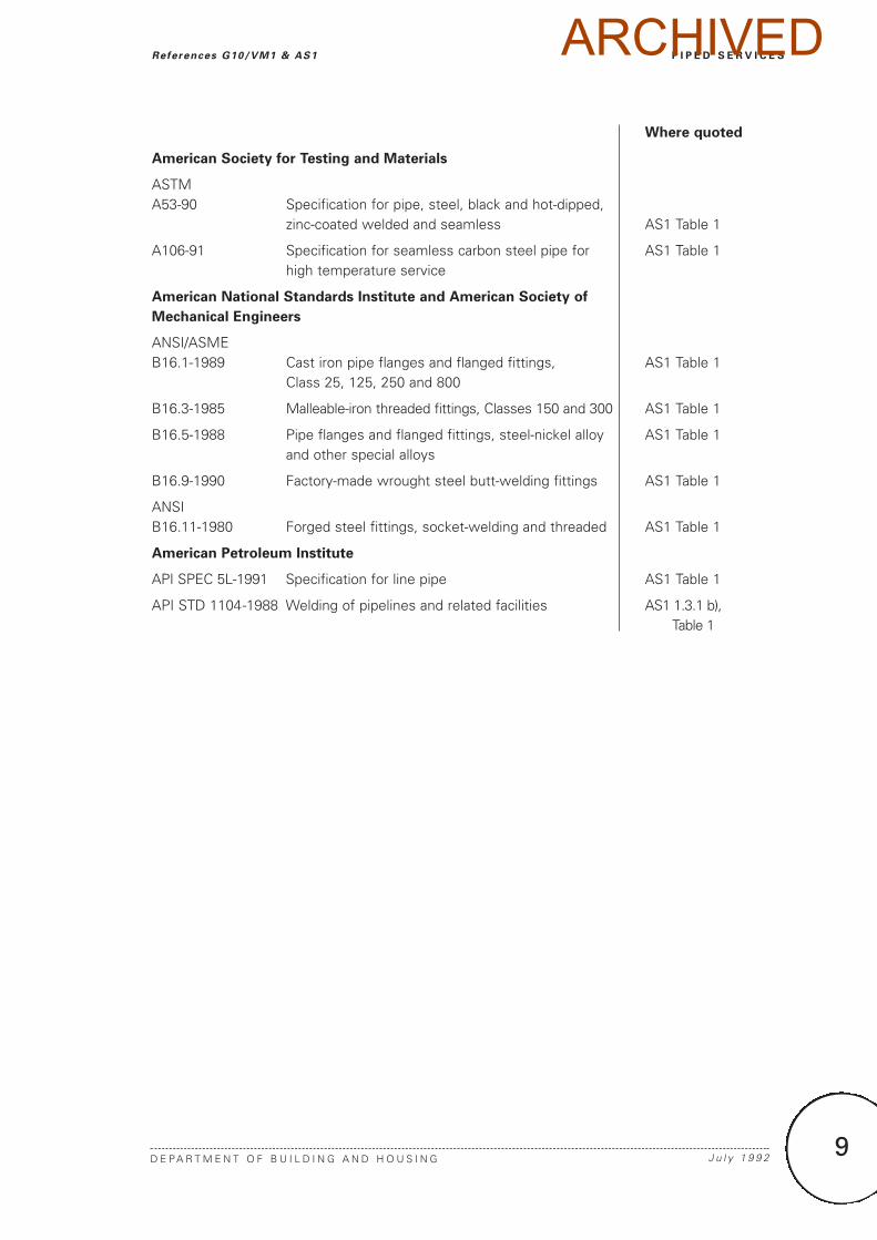
American Society for Testing and Materials
ASTM A53-90 Specification for pipe, steel, black and hot-dipped,
zinc-coated welded and seamless AS1 Table 1
A106-91 Specification for seamless carbon steel pipe for AS1 Table 1high temperature service
American National Standards Institute and American Society of
Mechanical Engineers
ANSI/ASMEB16.1-1989 Cast iron pipe flanges and flanged fittings, AS1 Table 1
Class 25, 125, 250 and 800
B16.3-1985 Malleable-iron threaded fittings, Classes 150 and 300 AS1 Table 1
B16.5-1988 Pipe flanges and flanged fittings, steel-nickel alloy AS1 Table 1and other special alloys
B16.9-1990 Factory-made wrought steel butt-welding fittings AS1 Table 1
ANSIB16.11-1980 Forged steel fittings, socket-welding and threaded AS1 Table 1
American Petroleum Institute
API SPEC 5L-1991 Specification for line pipe AS1 Table 1
API STD 1104-1988 Welding of pipelines and related facilities AS1 1.3.1 b), Table 1
9
P I P E D S E R V I C E S
D E P A R T M E N T O F B U I L D I N G A N D H O U S I N G J u l y 1 9 9 2
References G10/VM1 & AS1 ARCHIVED

10
ARCHIVED
11
P I P E D S E R V I C E S
D E P A R T M E N T O F B U I L D I N G A N D H O U S I N G 2 3 J u n e 2 0 0 7
Definit ions G10/VM1 & AS1
Adequate Adequate to achieve the objectivesof the building code.
Building has the meaning ascribed to it bySections 8 and 9 of the Building Act 2004.
Hazardous Creating an unreasonable risk to people of bodily injury or deterioration of health.
Intended use in relation to a building:
a) includes any or all of the following:
i) Any reasonably foreseeable occasional other use that is not incompatible with the intended use; and
ii) Normal maintenance; and
iii) Activities taken in response to fireor any other reasonably foreseeable emergency
b) but does not include any other maintenance and repairs or rebuilding.
Regulator A device which automaticallyregulates the pressure or volume of gaspassing through it to a predetermined level.
Safety shut-off system An arrangement ofvalves and associated control systemswhich shuts off the supply of gas whenrequired by a device which senses anunsafe condition.
Tailpipe A device placed at the low point of agas piping system to collect condensate,and from which the condensate may beremoved.
Vent line A pipe or tube which conveys gas toa safe place outside the building from a gaspressure regulator relief valve.
DefinitionsThis is an abbreviated list of definitions for words or terms particularly relevant to this ComplianceDocument. The definitions for any other italicised words may be found in the New ZealandBuilding Code Handbook.
Amend 4Jun 2007
Amend 4Jun 2007
Amend 4Jun 2007
ARCHIVED

12
ARCHIVED
13
P I P E D S E R V I C E S
D E P A R T M E N T O F B U I L D I N G A N D H O U S I N G 2 3 J u n e 2 0 0 7
Veri f icat ion Method G10/VM1
1.0 Soundness Testing
1.0.1 NZS 5261 Appendix D describesacceptable test methods to establish thatpiping systems will withstand a forseeablepressure without significant leakage.
Verification Method G10/VM1
Amend 4Jun 2007
ARCHIVED

14
ARCHIVED
1.0 Pipework Construction
1.0.1 Pipework installed in buildings shall:
a) Be designed in accordance with NZS 4203,and comply with the seismic design andinstallation requirements of NZS 4219,
b) Use materials and jointing techniquescomplying with Table 1,
c) Have no plain nipples, square back elbowsor long screws, and
d) Have metal (including spirally wound metal)gaskets with a minimum melting point of500°C.
COMMENT:
Pipework can be identified using the markingconventions given by NZS 5807.
1.1 Drainage and cleaning provisions
1.1.1 Where condensates can form in apipeline, they shall be removed by grading thepipe with a fall of 4 mm per metre towards atailpipe (drip), located at the piping low pointnearest the outlet side of the meter.
1.1.2 If this is impractical, a single tailpipe maybe provided at the lowest point in the pipeline,which shall have a fall to that point.
1.1.3 Tailpipes
Tailpipes shall be:
a) Constructed to provide:
i) ready access for cleaning and draining,
ii) a trap which on filling will shut off theflow of gas before the condensate canrun back to the meter, and
iii) protection from frost,
b) Of sufficient capacity for:
i) the pipes draining into them, and
ii) the amount of condensate likely tooccur, and
c) Installed with a suitable control fitting andplug to allow removal of condensate if thetailpipe is below ground.
1.2 Pipework installation
1.2.1 A pipework installation shall have:
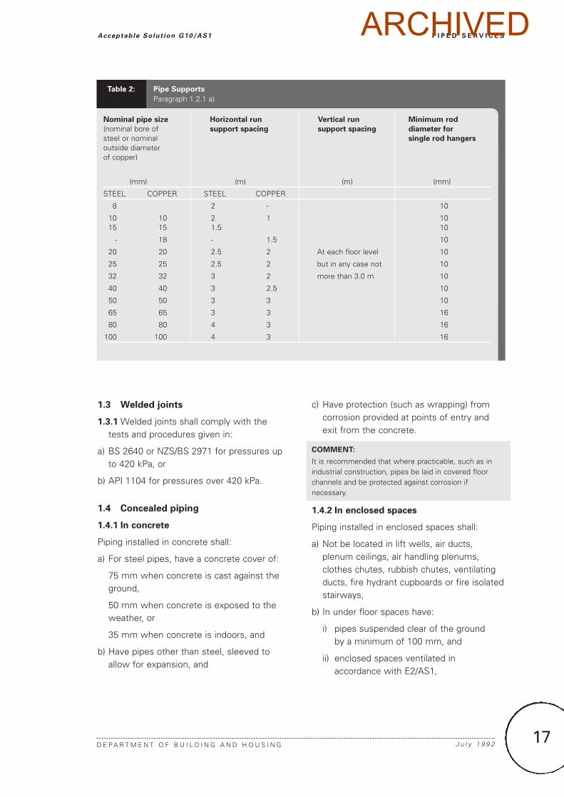
a) Pipes supported in accordance with Table 2,
b) Pipes separated (by at least 25 mm) fromany metallic electrical conduit, or metalarmoured or metal sheathed electrical wire,
c) Pipe risers which are:
i) supported by anchors and attachments which are capable of supporting the total weight of the riser and allow for differential expansion,
ii) sleeved through floors,
iii)not jointed at sleeve locations, and
d) Pipe bends and offsets which:
i) are constructed without buckling, cracks,or physical damage, and
ii) give at least the gas-carrying capacity of a standard fitting, and
e) No piping laid on the ground.
15
P I P E D S E R V I C E S
D E P A R T M E N T O F B U I L D I N G A N D H O U S I N G S e p t e m b e r 1 9 9 3
Acceptable Solut ion G10/AS1
Acceptable Solution G10/AS1It is intended that the New Zealand Building Code will in due course provide acceptable solutionsfor piping a range of fluids and solids. This acceptable solution is restricted to the reticulation ofgas (typically natural or town gas), used as an energy source.
For water supply piping, an acceptable solution is given in G12/AS1.
Piping for Gas used as an Energy Source
Amend 1Sep 1993
ARCHIVED
S e p t e m b e r 1 9 9 3 D E P A R T M E N T O F B U I L D I N G A N D H O U S I N G16
P I P E D S E R V I C E S Acceptable Solut ion G10/AS1
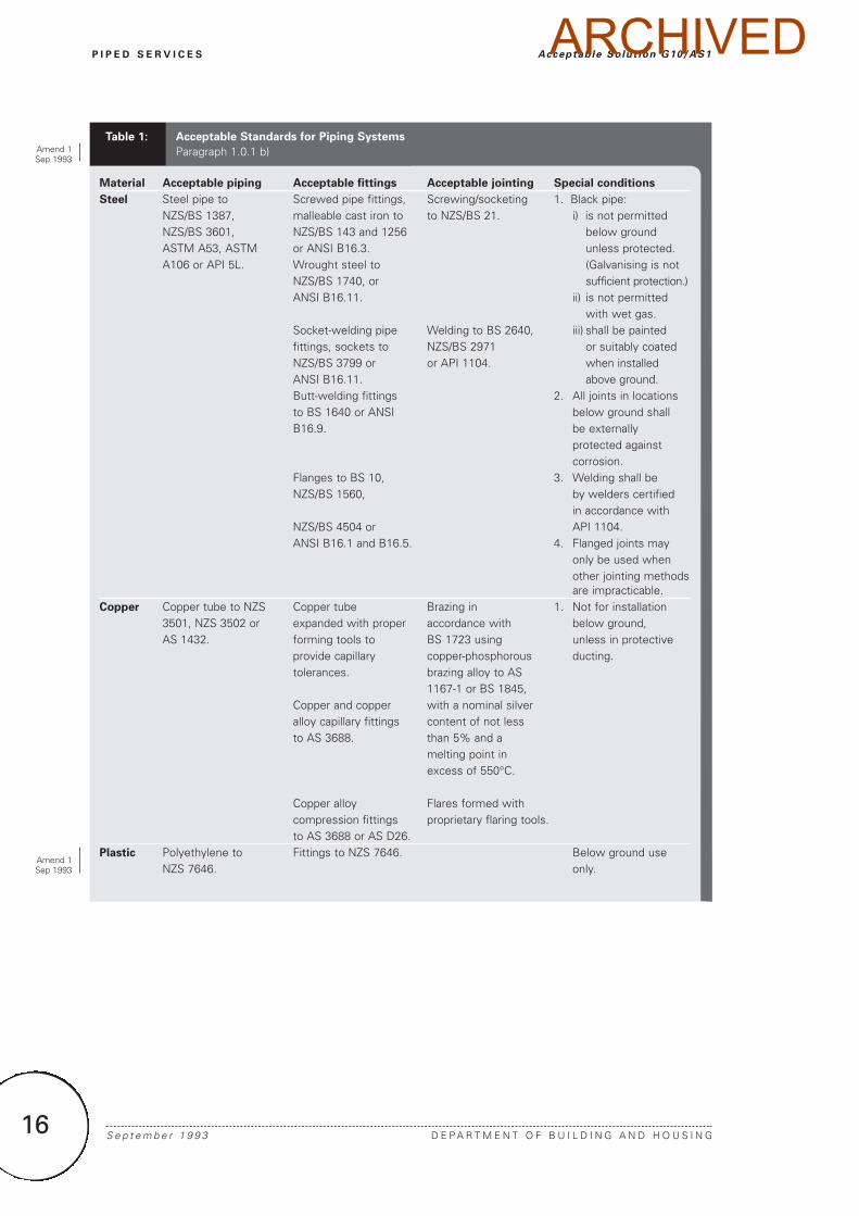
Material Acceptable piping Acceptable fittings Acceptable jointing Special conditions
Steel Steel pipe to Screwed pipe fittings, Screwing/socketing 1. Black pipe:NZS/BS 1387, malleable cast iron to to NZS/BS 21. i) is not permittedNZS/BS 3601, NZS/BS 143 and 1256 below ground ASTM A53, ASTM or ANSI B16.3. unless protected.A106 or API 5L. Wrought steel to (Galvanising is not
NZS/BS 1740, or sufficient protection.)ANSI B16.11. ii) is not permitted
with wet gas.Socket-welding pipe Welding to BS 2640, iii) shall be paintedfittings, sockets to NZS/BS 2971 or suitably coatedNZS/BS 3799 or or API 1104. when installed ANSI B16.11. above ground.Butt-welding fittings 2. All joints in locationsto BS 1640 or ANSI below ground shall B16.9. be externally
protected againstcorrosion.
Flanges to BS 10, 3. Welding shall beNZS/BS 1560, by welders certified
in accordance withNZS/BS 4504 or API 1104.ANSI B16.1 and B16.5. 4. Flanged joints may
only be used whenother jointing methodsare impracticable.
Copper Copper tube to NZS Copper tube Brazing in 1. Not for installation3501, NZS 3502 or expanded with proper accordance with below ground,AS 1432. forming tools to BS 1723 using unless in protective
provide capillary copper-phosphorous ducting.tolerances. brazing alloy to AS
1167-1 or BS 1845,Copper and copper with a nominal silveralloy capillary fittings content of not lessto AS 3688. than 5% and a
melting point inexcess of 550°C.
Copper alloy Flares formed withcompression fittings proprietary flaring tools.to AS 3688 or AS D26.
Plastic Polyethylene to Fittings to NZS 7646. Below ground useNZS 7646. only.
Acceptable Standards for Piping Systems
Paragraph 1.0.1 b)Table 1:
Amend 1Sep 1993
Amend 1Sep 1993
ARCHIVED
1.3 Welded joints
1.3.1 Welded joints shall comply with thetests and procedures given in:
a) BS 2640 or NZS/BS 2971 for pressures upto 420 kPa, or
b) API 1104 for pressures over 420 kPa.
1.4 Concealed piping
1.4.1 In concrete
Piping installed in concrete shall:
a) For steel pipes, have a concrete cover of:
75 mm when concrete is cast against theground,
50 mm when concrete is exposed to theweather, or
35 mm when concrete is indoors, and
b) Have pipes other than steel, sleeved toallow for expansion, and
c) Have protection (such as wrapping) fromcorrosion provided at points of entry andexit from the concrete.
COMMENT:
It is recommended that where practicable, such as inindustrial construction, pipes be laid in covered floorchannels and be protected against corrosion ifnecessary.
1.4.2 In enclosed spaces
Piping installed in enclosed spaces shall:
a) Not be located in lift wells, air ducts,plenum ceilings, air handling plenums,clothes chutes, rubbish chutes, ventilatingducts, fire hydrant cupboards or fire isolatedstairways,
b) In under floor spaces have:
i) pipes suspended clear of the ground by a minimum of 100 mm, and
ii) enclosed spaces ventilated in accordance with E2/AS1,
17
P I P E D S E R V I C E S
D E P A R T M E N T O F B U I L D I N G A N D H O U S I N G J u l y 1 9 9 2
Acceptable Solut ion G10/AS1
Pipe Supports
Paragraph 1.2.1 a)
Nominal pipe size Horizontal run Vertical run Minimum rod
(nominal bore of support spacing support spacing diameter for
steel or nominal single rod hangers
outside diameterof copper)
(mm) (m) (m) (mm)
STEEL COPPER STEEL COPPER
8 2 - 10
10 10 2 1 1015 15 1.5 10
- 18 - 1.5 10
20 20 2.5 2 At each floor level 10
25 25 2.5 2 but in any case not 10
32 32 3 2 more than 3.0 m 10
40 40 3 2.5 10
50 50 3 3 10
65 65 3 3 16
80 80 4 3 16
100 100 4 3 16
Table 2:
ARCHIVED
c) In unventilated and/or inaccessible spacesbe installed without joints, and
d) Where joints are unavoidable, have the jointinspected, tested and proved sound beforethe pipework is concealed.
1.4.3 Underground
Underground pipes shall be:
a) Sleeved and sealed where they penetratefoundation walls,
COMMENT:
The pipes are sleeved and sealed to prevent gas leakageto the building, and damage to the pipe resulting fromdifferential settlement.
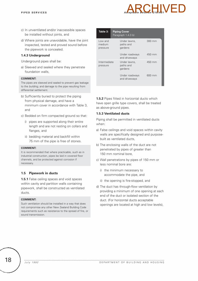
b) Sufficiently buried to protect the pipingfrom physical damage, and have aminimum cover in accordance with Table 3,and
c) Bedded on firm compacted ground so that:
i) pipes are supported along their entire length and are not resting on collars and flanges, and
ii) bedding material and backfill within 75 mm of the pipe is free of stones.
COMMENT:
It is recommended that where practicable, such as inindustrial construction, pipes be laid in covered floorchannels, and be protected against corrosion ifnecessary.
1.5 Pipework in ducts
1.5.1 False ceiling spaces and void spaceswithin cavity and partition walls containingpipework, shall be constructed as ventilatedducts.
COMMENT:
Such ventilation should be installed in a way that doesnot compromise any other New Zealand Building Coderequirements such as resistance to the spread of fire, orsound transmission.
1.5.2 Pipes fitted in horizontal ducts whichhave open grille type covers, shall be treatedas above-ground pipes.
1.5.3 Ventilated ducts
Piping shall be permitted in ventilated ductswhen:
a) False ceilings and void spaces within cavitywalls are specifically designed and purpose-built as ventilated ducts,
b) The enclosing walls of the duct are notpenetrated by pipes of greater than 150 mm nominal bore,
c) Wall penetrations by pipes of 150 mm orless nominal bore are:
i) the minimum necessary to accommodate the pipe, and
ii) the opening is fire-stopped, and
d) The duct has through-flow ventilation byproviding a minimum of one opening at eachend of the duct or isolated section of theduct. (For horizontal ducts acceptableopenings are located at high and low levels),
J u l y 1 9 9 2 D E P A R T M E N T O F B U I L D I N G A N D H O U S I N G18
P I P E D S E R V I C E S Acceptable Solut ion G10/AS1
Low and Under lawns, 300 mmmedium paths andpressure gardens
Under roadways 450 mmand driveways
Intermediate Under lawns, 450 mmpressure paths and
gardens
Under roadways 600 mmand driveways
Table 3: Piping Cover
Paragraph 1.4.3 b)
ARCHIVED
e) A minimum free ventilation opening of1/150 of the cross-sectional area of the ductor 50,000 mm2 whichever is the greater, isprovided, and
f) Pipes within horizontal ducts are locatednear the bottom of the duct.
1.5.4 Unventilated ducts
The installation of pipes in unventilated ductsshould be avoided, but when it is necessaryfor a pipe to pass through an unventilated ductor void, either:
a) The pipes shall be continuously sleevedwith the sleeve ventilated at one or bothends into a ventilated space, or
b) The duct void shall be filled with dry,washed sand.
COMMENT:
Dry, washed sand is acceptable because it is inert, non-combustible and non-corrosive.
2.0 Isolating Valves
2.0.1 Gas piping isolating valves shall:
a) For emergency shut-down of commercialand industrial installations, have theirlocation clearly identified on a drawingpermanently and prominently displayednear the primary meter set.
b) For appliances, be of the 1/4 turn type withthe handle marked to indicate the directionof gas flow.
c) For domestic and light commercialinstallations, be provided in an accessiblelocation outside the building.
2.0.2 To satisfy Paragraph 2.0.1 b), the meterinlet-valve may be used as an isolating valve inaccordance with the requirements of the gassupply authority.
3.0 Corrosion Control
3.0.1 Acceptable solutions for the control ofpipework corrosion shall provide for:
a) The installation of a joint which iselectrically non-conducting, where a piperises above ground,
b) The separation of electrochemicallyincompatible materials in undergroundlocations, by joining with insulatedcomponents, and
c) The painting of black steel pipe as soon aspracticable after installation unless it isprotected with anti-corrosive wrapping.
4.0 Vent Lines
4.0.1 Vent lines shall:
a) Be fitted to all vented safety shut-offsystems, gas pressure relief devices, andbreather vents, installed within a building,
b) Have the vent pipe discharge point locatedno closer than:
i) 1.0 m in any direction from an opening into a building, and
ii) 2.0 m from any source of ignition, and
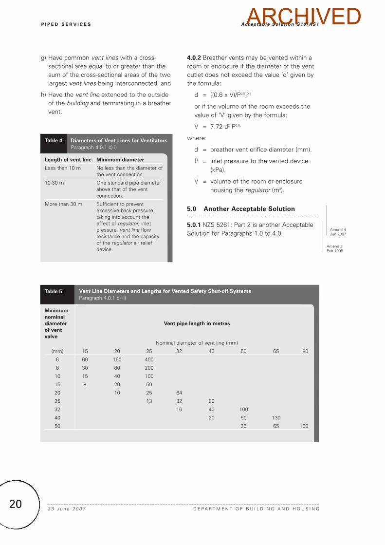
c) Have vent line diameters complying with:
i) Table 4 for ventilators, or
ii) Table 5 for a vented safety shut-off system, and
d) Have no vent lines of different typesinterconnected,
e) Have no breather vent connected to asafety system shut-off vent,
f) Have vent lines from the same applianceinterconnected for:
i) safety shut-off vent lines, and
ii) breather vent lines, and
19
P I P E D S E R V I C E S
D E P A R T M E N T O F B U I L D I N G A N D H O U S I N G S e p t e m b e r 1 9 9 3
Acceptable Solut ion G10/AS1
Amend 1Sep 1993
ARCHIVED
g) Have common vent lines with a cross-sectional area equal to or greater than thesum of the cross-sectional areas of the twolargest vent lines being interconnected, and
h) Have the vent line extended to the outsideof the building and terminating in a breathervent.
4.0.2 Breather vents may be vented within aroom or enclosure if the diameter of the ventoutlet does not exceed the value ‘d’ given bythe formula:
d = [(0.6 x V)/P0.5]0.5
or if the volume of the room exceeds thevalue of ‘V’ given by the formula:
V = 7.72 d2 P0.5
where:
d = breather vent orifice diameter (mm).
P = inlet pressure to the vented device (kPa).
V = volume of the room or enclosure housing the regulator (m3).
5.0 Another Acceptable Solution
5.0.1 NZS 5261: Part 2 is another AcceptableSolution for Paragraphs 1.0 to 4.0.
2 3 J u n e 2 0 0 7 D E P A R T M E N T O F B U I L D I N G A N D H O U S I N G20
P I P E D S E R V I C E S Acceptable Solut ion G10/AS1
Length of vent line Minimum diameter
Less than 10 m No less than the diameter of the vent connection.
10-30 m One standard pipe diameterabove that of the vent connection.
More than 30 m Sufficient to prevent excessive back pressuretaking into account theeffect of regulator, inlet pressure, vent line flowresistance and the capacity of the regulator air relief device.
Table 4: Diameters of Vent Lines for Ventilators
Paragraph 4.0.1 c) i)
Vent Line Diameters and Lengths for Vented Safety Shut-off Systems
Paragraph 4.0.1 c) ii)
Minimum
nominal
diameter Vent pipe length in metres
of vent
valve
Nominal diameter of vent line (mm)
(mm) 15 20 25 32 40 50 65 80
6 60 160 400
8 30 80 200
10 15 40 100
15 8 20 50
20 10 25 64
25 13 32 80
32 16 40 100
40 20 50 130
50 25 65 160
Table 5:
Amend 4Jun 2007
Amend 3Feb 1998
ARCHIVED
21
P I P E D S E R V I C E S
D E P A R T M E N T O F B U I L D I N G A N D H O U S I N G 2 3 J u n e 2 0 0 7
Index G10/VM1 & AS1
Index G10/VM1 & AS1All references to Verification Methods and Acceptable Solutions are preceded by VM or AS
respectively.
Gas reticulation
another Acceptable Solution . . . . . . . . . . . . . . . . . . . . . . . . . .AS1 5.0cleaning
see drainage . . . . . . . . . . . . . . . . . . . . . . . . . . . . . . . . . . .AS1 1.1concealed piping . . . . . . . . . . . . . . . . . . . . . . . . . . . . . . . . . . .AS1 1.4
in concrete . . . . . . . . . . . . . . . . . . . . . . . . . . . . . . . . . . .AS1 1.4.1in enclosed spaces . . . . . . . . . . . . . . . . . . . . . . . . . . . . .AS1 1.4.2underground . . . . . . . . . . . . . . . . . . . . . . . . . . .AS1 1.4.3, Table 3
construction . . . . . . . . . . . . . . . . . . . . . . . . . . . . . . . . . . . . . .AS1 1.0corrosion control . . . . . . . . . . . . . . . . . . . . . . . . . . . . . . . . . . .AS1 3.0design . . . . . . . . . . . . . . . . . . . . . . . . . . . . . . . . . . . . . . .AS1 1.0.1 a)drainage . . . . . . . . . . . . . . . . . . . . . . . . . . . . . . . . . . . . . . . . .AS1 1.1
tailpipes . . . . . . . . . . . . . . . . . . . . . . . . . . . . . . . . . . . . .AS1 1.1.3installation . . . . . . . . . . . . . . . . . . . . . . . . . . . . . . . . . . . . . . . .AS1 1.2
bends and offsets . . . . . . . . . . . . . . . . . . . . . . . . . . .AS1 1.2.1 d)risers . . . . . . . . . . . . . . . . . . . . . . . . . . . . . . . . . . . . . .AS1 1.2.1 c)separation . . . . . . . . . . . . . . . . . . . . . . . . . . . . . . . . . .AS1 1.2.1 b)supports . . . . . . . . . . . . . . . . . . . . . . . . . . . .AS1 1.2.1 a), Table 2
isolating valves . . . . . . . . . . . . . . . . . . . . . . . . . . . . . . . . . . . .AS1 2.0materials . . . . . . . . . . . . . . . . . . . . . . . . . . . . . . .AS1 1.0.1 b), Table 1pipework in ducts . . . . . . . . . . . . . . . . . . . . . . . . . . . . . . . . . .AS1 1.5
unventilated ducts . . . . . . . . . . . . . . . . . . . . . . . . . . . . .AS1 1.5.4ventilated ducts . . . . . . . . . . . . . . . . . . . . . . . . . . . . . . .AS1 1.5.3
vent lines . . . . . . . . . . . . . . . . . . . . . . . . . . . .AS1 4.0, Tables 4 and 5welded joints . . . . . . . . . . . . . . . . . . . . . . . . . . . . . . . . . . . . .AS1 1.3
Test methods . . . . . . . . . . . . . . . . . . . . . . . . . . . . . . . . . . . . . . .VM1 1.0
Amend 1Sep 1993
Amend 1Sep 1993
Amend 1Sep 1993
Amend 4Jun 2007
ARCHIVED

22
ARCHIVED