Embed Size (px)
Citation preview
1
Compliance Guidance for FLUOROSCOPIC
QUALITY CONTROL 2nd Edition
New Jersey Department of Environmental Protection Bureau of X-ray Compliance PO Box 420, MC 25-01 Trenton NJ 08625-0420 FAX 609-984-5811 Website: www.xray.nj.gov
2/28/2017 2
ACKNOWLEDGEMENTS This 2nd Edition Fluoroscopic Guidance Document was prepared through the efforts, advice and input of many people. We offer our thanks to all the contributors. But we thank the staff at the Bureau of X-ray Compliance. DISCLAIMER This Compliance Guidance Document is not a substitute for the Department’s regulations and compliance is not required with the procedures in this document. The procedures and/or methods described in this document are provided for information only. Performing these procedures does not necessarily constitute Department approval or guarantee compliance. Reprinted material is quoted with permission and sources are documented. A wide variety of references are listed. Reasonable efforts have been made to publish reliable information. The Department of Environmental Protection and all its sub-units assume no responsibility for the validity of all the materials or for the consequences of their use.
2/28/2017 3
ACKNOWLEDGEMENTS ........................................................................................................................ 2 DISCLAIMER ............................................................................................................................................. 2 INTRODUCTION ....................................................................................................................................... 4 Fluoroscopic Quality Control ..................................................................................................................... 5
FREQUENCY ............................................................................................................................. 5 CONSISTENCY IS THE KEY! ................................................................................................. 5 COMPETENCY ......................................................................................................................... 5 TRAINING OPTIONS ................................................................................................................ 6 USING THIS GUIDANCE DOCUMENT ................................................................................. 6 ADDITIONAL DOCUMENTS AVAILABLE...................................................................... 6&7 TABLE 2 Fluoroscopic Quality Control Requirements .............................................................. 8
Equipment Warm-up ........................................................................................................................... 9&10 Laser Film Printer Quality Control ......................................................................................................... 11 Spot Film and Radiography ..................................................................................................................... 12 Phantom Images (Fluoro Video Monitor) ............................................................................................... 13
Procedure 4A Phantom Set Up ................................................................................................ 14 Procedure 4B Establish Baseline Values for Phantom Image Evaluation .............................. 15 Procedure 4C Monthly Phantom Image Evaluation ........................................................ 16&17
Equipment Visual Checklist ..................................................................................................................... 18 Procedure 5 Equipment Visual Checklist ......................................................................... 18&19
Lead aprons, gloves, gonadal and thyroid shielding integrity check .................................................... 20 Procedure 6 Lead Shielding Integrity Check ............................................................................ 20
Medical Physicist’s Fluoroscopic QC Survey ......................................................................................... 21 Table 5 Medical Physicist’s Fluoroscopic QC Survey............................................................ 21
Quality Assurance Program Review ....................................................................................................... 22 Quality Assurance Program Review Requirements ................................................... 23, 24 & 25
BIBLIOGRAPHY .............................................................................................................................. 26&27 FORMS ...................................................................................................................................................... 28
Form 1 Visual Equipment Checklist ..................................................................................... 29 Form 2 Laser Film Printer Control Chart .............................................................................. 30 Form 3 Phantom Image (Fluoro Video Monitor) .................................................................. 31 Form 4 Quality Control Log - Annual Tests .......................................................................... 32
2/28/2017 4
INTRODUCTION On January 16, 2001, the Department of Environmental Protection (Department) and the Commission on Radiation Protection adopted regulations (New Jersey Administrative Code 7:28-22) that require all facilities performing diagnostic x-ray procedures (radiology, fluoroscopy, x-ray bone densitometry or computed tomography) to develop and continually implement a Quality Assurance program. The regulations apply to equipment used on humans in hospital, medical, podiatric, chiropractic, dental, industrial, school, and government facilities. This document provides guidance for performing QC tests for fluoroscopic equipment. Additional compliance guidance documents are available for the QA Manual, Computed Tomography and Radiographic Quality Control. See the section entitled, “Additional Documents Available” for information on receiving these documents. A Quality Assurance (QA) program, which includes quality control tests, helps to ensure that high quality diagnostic images are consistently produced while minimizing radiation exposure. The QA program covers the entire x-ray system from machine, to producing diagnostic images. This program will enable the facility to recognize when parameters are out of limits, which will result in poor quality images and can increase the radiation exposure to patients. Simply performing the quality control tests is not sufficient. When quality control test results exceed established operating parameters, appropriate corrective action must be taken immediately and documented. This guide is intended to assist the facility in setting up their QA Program and performing the quality control tests required to maintain high quality images and reduce patient exposure. This guide includes generally accepted procedures that the facility may use to perform the required tests. The procedures in this guide are not the only way to perform the tests. Alternative test procedures may be used without Department approval. However, all procedures being used must be documented in the facility’s QA Manual and meet the requirements of N.J.A.C. 7:28-22. In some cases, manufacturers' directions may be more appropriate than the generic procedures in this guide. Product manufacturers, vendors, and service companies all have information available on their website and operator manuals. If the facility finds that they need more instruction than this guide provides, please use these companies and your medical physicist as resources. The responsibility for the quality control tests should be assigned to a QA program coordinator to ensure consistency in test methodology and interpretation of the data. More than one person may perform the tests but one person should assume overall responsibility for the day to day operation of the program. This leads to better understanding of when to repeat tests, call for service, or consult with the practitioner or medical physicist. The physician, medical physicist, and QC personnel, working together as a team, are the key to providing optimum quality Fluoroscopic images.
2/28/2017 5
Fluoroscopic Quality Control
The regulation requires that each facility with fluoroscopic equipment perform, or have performed, the tests in Table 2 Fluoroscopic Quality Control Requirements, at least at the frequency specified, and maintain records of the test results. FREQUENCY The frequency of tests specified in Table 2 is the minimum frequency. The frequency of quality control tests may need to be increased depending on many factors including the age and stability of the x-ray equipment and film processing equipment, as well as the number of problems being encountered. Tests may always be performed at a GREATER frequency than required by N.J.A.C. 7:28-22. Tests may NOT be performed at frequencies LESS than required in N.J.A.C. 7:28-22 unless approved by the Department as outlined in N.J.A.C. 7:28-22.3(f). For example, if the facility decides to perform the Equipment Visual Checklist monthly, this new frequency must be documented in the facility’s QA manual and the test data needs to be recorded appropriately. CONSISTENCY IS THE KEY! After each link (fluoroscopic imaging unit, video monitor, spot films, etc.) in the imaging chain is optimized, a working QA program will provide warning flags to the QA program coordinator when something goes awry. If the coordinator finds, that the established tolerances are exceeded, the test or tests must be repeated to verify the results, then corrective action must be taken. The coordinator must be capable of identifying problems and willing to resolve them as they occur, or the QA program will not provide the intended benefits. COMPETENCY The registrant, per N.J.A.C. 7:28-22.6(c), must ensure that all individuals, performing any of the quality control tests, have an appropriate level of training to perform the tests competently. The regulations do not specify that a physician, a radiologic technologist or a physicist must perform the tests. Anyone with adequate training can perform quality control tests (The only exception is the Medical Physicist’s QC Survey which must be performed by a Medical Physicist meeting the requirements of N.J.A.C. 7:28-22). The level of training required depends on the test being assigned. Some procedures such as darkroom cleaning require minimal training. Performing the Phantom Images (Fluoro Video Monitor) procedure requires more training. The facility must ensure that there are sufficient trained personnel so that there is always someone available (i.e. to cover vacation and sick time) to perform the necessary testing.
2/28/2017 6
TRAINING OPTIONS The registrant may train their personnel. This assumes that the registrant is competent in the procedure and can convey this knowledge adequately to the personnel. Product manufacturers, vendors, and service companies have training aids available on the intranet. Companies whose sole purpose is training as well as service and repair companies and the facility’s medical physicist can provide seminars and training courses ranging from a few hours to several days or more on the how to perform Quality Control tests. Adequate training of personnel will ensure that the tests are performed correctly and consistently. USING THIS GUIDANCE DOCUMENT This document is intended to provide guidance for performing QC tests for fluoroscopic machines only. Additional compliance guidance documents are available for the QA Manual, Radiographic QC tests and CT QC tests. See the section entitled, “Additional Documents Available” for information on receiving these documents. Several other documents are listed in the last section that the facility might find useful. A detailed description of each required test follows in the order listed in Table 2. This is the same table that appears in the regulation at N.J.A.C. 7:28-22.6. Records of Quality Control test results, corrective actions, Medical Physicist’s QC Survey, and Quality Assurance Program Review must be maintained for at least the time specified in Table 1 (page 8). Sample forms can be found in the FORMS section beginning on page 27 of this document. Forms provided here may be modified to meet facility needs if sufficient information is included to demonstrate compliance. ADDITIONAL DOCUMENTS AVAILABLE Compliance Guidance for QA Manual: this document provides guidance in setting up a QA program, assignment of QC testing to various individuals, and the information required to be maintained at the facility. Compliance Guidance for Radiographic Quality Control: this document contains detailed descriptions for performing the QC tests required for radiographic machines. Facilities using fluoroscopic machines for spot films and/or radiography please note that this document contains procedures for the QC tests for spot film/radiography that you need to perform. Compliance Guidance for Computed Tomography Quality Control: this document contains detailed descriptions for performing the QC tests required for computed tomography machines. Radiation Safety Manual: this document provides guidance to setting up the radiation safety manual as required by N.J.A.C. 7:28-15.9(a) 8.
2/28/2017 7
List of Qualified Medical Physicists for QC Surveys: certain tests must be performed by or under the direction of a medical physicist meeting certain educational and experience requirements. This document contains a current list of individuals who meet the requirements of N.J.A.C. 7:29-22. List of Qualified Individuals for The Performance of Radiation Safety Surveys of the Environs: this document contains the names of individuals who meet the educational and experience requirements in N.J.A.C. 7:28 to perform radiation safety surveys of the environs on x-ray equipment. The individuals on this list are not necessarily the same individuals as on the qualified medical physicists for QC surveys list. Commercial Personnel Monitoring Services: this document contains the names of companies that provide personnel radiation monitoring devices (badges). Assemblers list: this document contains a list of vendors who sell and repair x-ray equipment. Copies of these documents and other information can be obtained from the Department’s website: www.xray.nj.gov
2/28/2017 8
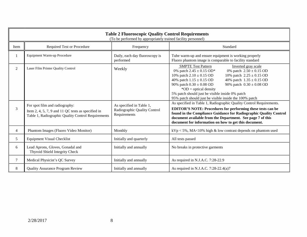
Table 2 Fluoroscopic Quality Control Requirements
(To be performed by appropriately trained facility personnel)
Item
Required Test or Procedure
Frequency
Standard
1 Equipment Warm-up Procedure
Daily, each day fluoroscopy is performed
Tube warm-up and ensure equipment is working properly Fluoro phantom image is comparable to facility standard
2
Laser Film Printer Quality Control
Weekly SMPTE Test Pattern Inverted gray scale
0% patch 2.45 ± 0.15 OD* 0% patch 2.50 ± 0.15 OD 10% patch 2.10 ± 0.15 OD 10% patch 2.25 ± 0.15 OD 40% patch 1.15 ± 0.15 OD 40% patch 1.35 ± 0.15 OD 90% patch 0.30 ± 0.08 OD 90% patch 0.30 ± 0.08 OD *OD = optical density 5% patch should just be visible inside 0% patch 95% patch should just be visible inside the 100% patch
3
For spot film and radiography: Item 2, 4, 5, 7, 9 and 11 QC tests as specified in Table 1, Radiographic Quality Control Requirements
As specified in Table 1, Radiographic Quality Control Requirements
As specified in Table 1, Radiographic Quality Control Requirements. EDITOR’S NOTE: Procedures for performing these tests can be found in the Compliance Guidance for Radiographic Quality Control document available from the Department. See page 7 of this document for information on how to get this document.
4
Phantom Images (Fluoro Video Monitor)
Monthly
kVp < 5%, MA<10% high & low contrast depends on phantom used
5
Equipment Visual Checklist
Initially and quarterly
All tests passed
6
Lead Aprons, Gloves, Gonadal and Thyroid Shield Integrity Check
Initially and annually
No breaks in protective garments
7
Medical Physicist’s QC Survey
Initially and annually
As required in N.J.A.C. 7:28-22.9
8
Quality Assurance Program Review
Initially and annually
As required in N.J.A.C. 7:28-22.4(a)7
2/28/2017 9
Procedure 1A Equipment Warm-up and Image Evaluation NOTE: because this procedure necessitates activation of the fluoroscopic tube, the surveyor should make certain the image quality test tool is attenuating the useful x-ray beam during operation and wear appropriate protective equipment (lead apron, gloves, thyroid shield, etc.) Equipment Required: Image quality test tool containing a series of cooper mesh patterns, line pairs or other test objects and circular depressions (holes) of various depths in an aluminum disk -OR- another test tool as recommended by fluoroscopic unit’s manufacturer or the medical physicist. Copper attenuator 1/16" thickness (some test tools incorporate the attenuator into the device) Follow the set-up requirements of the test tool you are using. In general: 1. Remove all pads from table surface. 2. Disengage compression cone, if present, and move out of field of view. 3. Position anti-scatter grid according to clinical use. 4. FOR UNDER TABLE TUBE SYSTEMS: Place the Image quality test tool and copper
attenuator table top. Position the fluoro gantry at 12 inches from the tabletop. FOR C-ARM SYSTEMS: Rotate the c-arm to position the fluoro tube above image intensifier. Place the Image quality test tool and copper attenuator on top of the image intensifier. FOR OVER TABLE TUBE SYSTEMS: Place the Image quality test tool and copper attenuator on the tabletop.
5. Select the same image intensifier field of view mode used for Phantom Images (Fluoro Video Monitor)
6. Center the Image quality test tool under fluoroscopy. 7. Adjust collimators to completely open and completely closed positions to verify the
operation of the collimators. Return collimators to fully open position. 8. Adjust room lighting conditions to those used clinically. Observe the Image quality test
tool under fluoroscopy. When adjusted correctly, the low contrast holes and meshes will be seen. Observe the mesh patterns, line pairs or other test objects under fluoroscopy. The image should be sharp. When the quality assurance program is first established, record the number of mesh patterns, line pairs or other test objects seen as the baseline measurement. For subsequent measurements, ensure that the resolution has not decreased.
9. If needed, and the controls are available, adjust the monitor brightness and contrast. 10. If spot films are routinely used, acquire a spot film image to check the function of the
device. Use the image size, technique and filming format most commonly used clinically. Retain initial films for subsequent testing comparison. When the quality assurance program is first established, record the number of mesh patterns, line pairs or other test objects seen as the baseline measurement. For subsequent measurements, ensure that the resolution has not decreased. Look for artifacts in the processed spot-film image.
11. If digital photo-spot images are routinely used, check the operation of the system by
2/28/2017 10
acquiring several images using the technique most commonly used clinically. Print a hard copy image using the most frequently used film format. Retain initial films for subsequent testing comparison. When the quality assurance program is first established, record the number of mesh patterns seen as the baseline measurement. For subsequent measurements, ensure that the resolution has not decreased.
CORRECTIVE ACTION: If during the warm up a malfunction occurs, immediately initiate steps to repair the fluoro equipment. If resolution has degraded from baseline, then perform the image evaluation test again or have the imaging physicist run more detailed tests. If test still does not meet the standard, then contact your service representative. Document steps to repair the fluoro equipment. RECORDS: There are no records required for daily equipment warm-up.
2/28/2017 11
ITEM 2 - Laser Film Printer Quality Control Test Frequency: Weekly In some clinical settings, the physician makes the diagnosis by reading the images from an image created with a laser film printer. The laser film printer should reproduce the quality and gray scale of the original image displayed on the system monitor. The procedure uses the Society of Motion Picture and Television Engineers (SMPTE) digital test pattern. The SMPTE test pattern is supplied with most laser printers or it can be obtained from accessory vendors. Generic procedures for performing Laser Film Printer Quality Control tests can be found in the Compliance Guidance for Radiographic Quality Control document available from the Department’s website: www.xray.nj.gov Equipment Required Form 2 Laser Film Printer Control Chart (page 30) CORRECTIVE ACTION: If the measurements indicate the Laser Film Printer Quality Control do meet specifications, immediately initiate steps to repair the Laser Film Printer to meet the standards. Perform the Laser Film Printer Quality Control test again or have the imaging physicist run more detailed tests. If test still does not meet the standard, then contact your service representative. Document steps to repair the Laser Film Printer to meet standards. Laser film shall not be processed until the processing meets the standards. All such repairs shall be completed within 30 days. RECORDS: Ensure records of each corrective action, repair and service are maintained for at least 2 years. Maintain all Laser Film Printer Quality Control test results, written record or digital, for at least one year. Maintain all images (film and/or digital) produce and relied upon in the performance of Laser Film Printer Quality Control testing for at least 30 days.

2/28/2017 12
ITEM 3 - Spot Film and Radiography
Facilities performing spot film, digital photo-spot images and/or radiography with their fluoroscopy equipment must also perform the following tests, as specified in Table 1, Radiographic Quality Control Requirements. Processor Quality Control Darkroom Cleanliness Processor Maintenance and Chemical Solutions Film and Chemical Shelf Life Light Field/X-ray Field Alignment Repeat Analysis Analysis of Fixer Retention Generic procedures for performing these tests can be found in the Compliance Guidance for Radiographic Quality Control document available from the Department’s website: www.xray.nj.gov CORRECTIVE ACTION: If any of the test results from Item 3 in Table 2, Fluoroscopic Quality Control Requirements, indicate that the x-ray equipment or processing does not meet the standards in Table 2, the registrant shall immediately initiate steps to bring the fluoroscopic equipment and processing into compliance. If processor sensitometry/densitometry does not meet the standards, films shall not be processed until the processing meets the sensitometry/ densitometry standards. RECORDS: Ensure records of each corrective action, repair and service are maintained for at least 2 years. Maintain all Laser Film Printer Quality Control test results, written record or digital, for at least one year. Maintain all images (film and/or digital) produce and relied upon in the performance of Laser Film Printer Quality Control testing for at least 30 days.
2/28/2017 13
ITEM 4 - Phantom Images (Fluoro Video Monitor) Test Frequency – Monthly Standards: kVp ± 5%, mA ± 10%, high & low contrast depends on phantom used To ensure that density, contrast, uniformity, and image quality due to the x-ray imaging system are maintained at optimum levels. NOTE: because this procedure necessitates activation of the fluoroscopic tube, the surveyor should make certain the image quality test tool is attenuating the useful x-ray beam during operation and wear appropriate protective equipment (lead apron, gloves, thyroid shield, etc.) Equipment Required Fluoroscopic Quality Control Phantom Form 3 Phantom Images (Fluoro Video Monitor) page 31 Because of the large variety in types of fluoroscopic equipment, the different types of studies they are used for, and the variety of Fluoroscopic Quality Control Phantoms available, the Department cannot make a specific recommendation for the facility as to which phantom is best for that facility. The phantom used should be one of the following: 1. The phantom recommended by the equipment manufacturer. 2. The phantom recommended by the medical physicist. Fluoroscopic Quality Control Phantoms typically contain copper mesh test patterns of varying mesh sizes, line pairs or other test objects which provide a measure of image sharpness (resolution) for evaluating high contrast. The Fluoroscopic Quality Control Phantoms also contains circular depressions (holes) of various depths or size for evaluating low contrast. The shallowest or smallest hole that can be detected is a measure of the low contrast perceptibility available in the x-ray system. A decrease in the number of holes detected can indicate an increase in system noise. Most Fluoroscopic Quality Control Phantoms also have a copper attenuator.

2/28/2017 14
Procedure 4A Follow the set-up requirements of the Fluoroscopic Quality Control Phantom you are using. In general: For under-table tubes: The table padding is removed. the Fluoroscopic Quality Control Phantom and cooper attenuator is set on the x-ray table top. The fluoroscopic tower is moved over the phantom and set to a height of about 12 inches above the table. Standardizing the height is important for ensuring reproducibility of the Quality Control testing. For C-ARM Systems: Rotate the c-arm to position the fluoro tube above image intensifier. Place the Image quality test tool and copper attenuator on top of the image intensifier. For over-table fluoroscopy tubes: The table padding is removed. The Fluoroscopic Quality Control Phantom and cooper attenuator is set directly on the tabletop. The phantom is centered using the light field from the overhead tube if available. Set the tube height to that normally use for fluoro. Standardizing the height is important for ensuring reproducibility of the Quality Control testing. Set up fluoroscopy unit The fluoroscopy system is set up as clinically utilized for the most common fluoroscopy exam performed at the facility. The image intensifier field of view (FOV) is set to the mode which will allow the entire phantom to be fully imaged. If the grid is normally used for fluoroscopy it should be in place. The compression cone, if any, should be removed. If the system has dose mode selection it should be set to the value normally used clinically. Fine Centering of Phantom Image WEAR PROTECTIVE GARMENTS (lead apron, gloves, thyroid shield, etc.) while performing this procedure! Activate the fluoro beam and move the fluoro tower as required to center the phantom on the image field. Cone down (close) the collimators until only edges of the phantom are visible. Re-center as necessary.
2/28/2017 15
Procedure 4B Establish Baseline Values for Phantom Image Evaluation Baseline values are established when the quality control program is initiated. The baseline values may need to be re-established after service if the service has increased the quality of the image and the number of meshes or holes seen exceeds standards or as recommended by your medical physicist. Re-establishment of the baseline values must never be done for bringing an out of limits fluoroscopy unit into compliance This procedure assumes that the phantom used has mesh patterns. If the phantom used has line pairs or other test objects in place of meshes, in steps 4 through 7, count and record the number of line pairs or other test objects seen and modify Form 3 to reflect the phantom used. 1. Complete top of Form 3. 2. With the phantom in position as in Procedure 4A, activate fluoro. Record the fluoro kVp and
mA from the control panel on Form 3 in the appropriate sections. 3. Determine the acceptable ranges for kVp and mA and record on Form 3 in the appropriate
sections. The standard is that the kVp must not change more than ± 5% and the mA must not change more than ± 10%. For example: a. If kVp is 90, acceptable ranges are 90 kVp ± 5% or 85.5 kVp to 94.5 kVp. b. If mA is 2.5, acceptable ranges are 2.5 mA ± 10% or 2.25 mA to 2.75 mA. c. View the fluoro image on the TV monitor, darken the room lights, and count the number
of mesh patterns of the test tool. You may view the monitor close and the monitor brightness may be adjusted to optimize visualization of the mesh pattern. A mesh pattern may be counted as visualized if the mesh (crisscross) lines can be seen.
d. Record this number on Form 3 in the appropriate section. e. Determine the acceptable limits for number of meshes visualized and record on Form 3 in
the appropriate section. f. For example: If the number of meshes visualized is 3, acceptable range is ± 1 mesh or 2
to 4 meshes seen. g. Count the number of low contrast holes you can visualize in the test tool. You may
count a hole as “seen” if you see in the image a full circle where the hole is located. h. Record this number on Form 3 in the appropriate section. i. Determine the acceptable limits for number of holes visualized and record on Form 3 in
the appropriate section. j. For example: If the number of holes visualized is 3, acceptable range is ± 1 hole or 3 to 4
holes seen.
2/28/2017 16
Procedure 4C Monthly Phantom Image Evaluation This procedure assumes that the phantom used has mesh patterns. If the phantom used has line pairs or other test objects in place of meshes, in steps 4 through 6, count and record the number of line pairs or other test objects seen and modify Form 3 to reflect the phantom used. 1. Record date and initials of person performing test in the appropriate sections on Form 3. 2. With the phantom in position as in Procedure 4A, activate fluoro. Record the fluoro kVp and
mA from the control panel on Form 3 in the appropriate sections. 3. Determine if the kVp and mA is within the acceptable ranges and record “yes or no” in the
“In Range?” section of Form 3 in the appropriate sections. 4. View the fluoro image on the TV monitor, darken the room lights, and count the number of
mesh patterns. A mesh pattern may be counted as visualized if the mesh (crisscross) lines can be seen.
5. Record this number on Form 3 in the appropriate section. 6. Determine if the number of meshes visualized is within the acceptable range and record “yes
or no” in the “In Range?” section of Form 3. 7. Count the number of low contrast holes you can visualize in the test tool. You may count a
hole as “seen” if you see in the image a full circle where the hole is located. 8. Record this number on Form 3 in the appropriate section. 9. Determine if the number of holes visualized is within the acceptable range and record “yes or
no” in the “In Range?” section of Form 3. 10. If any item on Form 3 is not within the acceptable range, determine the cause of the problem
and correct it. After correction retest and log these test scores on another line on Form 3. For kVp and mA changes: If the indicated kVp differs from the baseline value by more than 5% or the mA by more than 10%, recheck the setup of the phantom and fluoro system (fluoro tower centered, distance to phantom, fluoro FOV, etc.) If the setup is correct and the changes persists, then contact service personnel or the medical physicist. Decrease in number of meshes seen: If two or more mesh groups are not visualized and the kVp and mA value are the same, then try adjusting the monitor brightness if possible to optimize visualization. If no improvement is obtained, then contact service or the medical physicist. Decrease number of holes seen: If two holes are not visualized and the kVp value is the same, then try adjusting the monitor brightness if possible to optimize visualization. If no improvement is obtained, then contact service or the medical physicist. CORRECTIVE ACTION: If the measurements indicate the Fluoroscopic Quality Control Phantom testing does not meet
2/28/2017 17
standards, immediately initiate steps to repair the Fluoroscopic equipment to meet the standards. Perform the Fluoroscopic Quality Control Phantom test again or have the imaging physicist run more detailed tests. If test still does not meet the standard, then contact your service representative. Immediately initiate steps to repair the fluoroscopic equipment to meet the standards. All such repairs shall be completed within 30 days. RECORDS: Ensure records of each corrective action, repair and service are maintained for at least 2 years. Maintain all Fluoroscopic Quality Control Phantom test results, written record or digital, for at least one year.
2/28/2017 18
ITEM 5 -Equipment Visual Checklist Test Frequency - Initially and quarterly thereafter Standard - All tests passed The purpose of this checklist is to ensure that the fluoroscopic system is working properly and that the mechanical rigidity and stability of the equipment is maintained. The following is a list of items that should be checked. This list is generic. Items should be added or subtracted as they apply to the specific piece of equipment being evaluated. Each item should function as the manufacturer intended. Procedure 5 Equipment Visual Checklist Equipment Required: Form 1 Equipment Visual Checklist Form (page 29) NOTE 1: because some of the items on the Checklist necessitate activation of the fluoroscopic tube, the surveyor should make certain there is something (phantom, cubic water container, etc.) attenuating the useful x-ray beam during operation and wear appropriate protective equipment (lead apron, gloves, thyroid shield, etc.)
1. Review all the items on the Equipment Visual Checklist (Form 1 page 42) and record pass or fail. Each time a task is completed, the individual carrying out the task should write in date and initial the appropriate area on the checklist.
2. All foot and hand switches designed to energize the fluoroscopic tube should be tested to ensure that x-ray production is terminated as soon as the switch is released. If switches have multiple positions (example: high level control) each position should be tested.
3. The table, image intensifier, and tube, as applicable, should move smoothly and freely without requiring excessive force.
4. Check all the locks and centering detents on the tower and table for adequate function. 5. Verify that all the indicators, switches, lights and meters at the table, image intensifier and
control panel are functioning. (i.e. x-ray on light functions, kVp and mA indicators work, etc.).
6. Using each collimating option, test for smooth collimator blade motion. If applicable, vary the SID to assure the collimator tracks (i.e. automatically maintains the field size) as the SID changes.
7. Check that available grids smoothly move in and out of the useful beam. 8. Check that available compression devices easily move in and out of the useful beam and
function correctly. 9. Lead drapes should be affixed to the image intensifier (under table systems) and have no
creases or gaps that may subject the operator to unnecessary scatter radiation. 10. If the unit is an under table fluoroscopic system, check that the shield covering the Bucky
slot during fluoroscopy is working as designed. Check that the Bucky moves smoothly along the track and its locking mechanism is functioning.
2/28/2017 19
11. If the unit is a portable c-arm, it must be equipped with a spacer on the tube to prevent the patient from being closer than 30 cm to the tube’s target. This spacer must always be used unless it interferes with a sterile field as during surgery.
12. It must not be possible to activate the x-ray tube unless the entire fluoroscopic beam is intercepted by the image receptor. On systems where the image intensifier can be placed in a park position, do so and step on the pedal to assure that this interlock is functioning.
13. If there are interlocks on the door(s), check that they prevent the unit from producing radiation when the door is open.
14. Determine if the technique charts at the control panel are present and current. 15. Check that the fluoro timer emits an audible signal or terminates the exposure after 5
minutes expires. 16. Ensure only individuals required for the medical procedure, for training, or for
equipment maintenance shall be in the fluoroscopic room during an exposure. Individuals who are in the fluoroscopic room during any exposure shall wear protective aprons of at least 0.25 mm lead equivalent during every exposure. Protective gloves of at least 0.25 mm lead equivalent shall be worn by the fluoroscopist and assistant(s) during every examination when it is required that their hands be placed in the useful beam. Gonadal shielding of not less than 0.5 mm lead equivalent shall be used on a patient during fluoroscopic procedures, except for cases in which this would interfere with the diagnostic procedure. If the patient is sterile, the use of gonadal shielding may be omitted. Check if required lead apron, gloves, gonadal and thyroid shield are available for use during fluoroscopic procedures.
CORRECTIVE ACTION: If any of the tests on Equipment Visual Check list do not pass, immediately initiate steps to repair the Fluoroscopic equipment. All such repairs shall be completed within 30 days. RECORDS: Ensure records of each corrective action, repair and service are maintained for at least 2 years. Maintain all Equipment Visual Check list, written or digital record, for at least one year.
2/28/2017 20
ITEM 6 - Lead Aprons, Gloves, Gonadal and Thyroid Shielding Integrity Check
Test Frequency - Initially and annually thereafter Standard - No breaks in protective garments Examine the integrity of the personnel shielding devices to ensure optimal protection to the patient when positioned properly. NOTE: Lead aprons should never be folded. Cracks in the lead lining can develop at the fold, reducing the useful life of the apron. Do not assume that brand new aprons, gloves, etc. contain no defects. Visual examination is not sufficient to ensure integrity of shielding. New aprons, gloves, etc. should be examined under x-ray immediately upon arrival and returned to supplier if defects are found. Procedure 6 Lead Shielding Integrity Check Equipment required: Personnel shielding devices
Form 4 Quality Control Log - Annual Tests (page 32).
1. Lay out the item to be checked on the table. 2. Examine the entire item for breaks in the garment’s structure using the fluoroscope or
x-ray system. 3. Record on Quality Control Log - Annual Tests (Form 4).
CORRECTIVE ACTION: Lead Aprons, Gloves, Gonadal and Thyroid Shielding displaying breaks in the lead lining should be replaced or repaired immediately. All such repairs shall be completed within 30 days. RECORDS: Ensure records of each corrective action, repair and service are maintained for at least 2 years. Maintain results of Lead Shielding Integrity Check, written or digital record, for at least one year.
2/28/2017 21
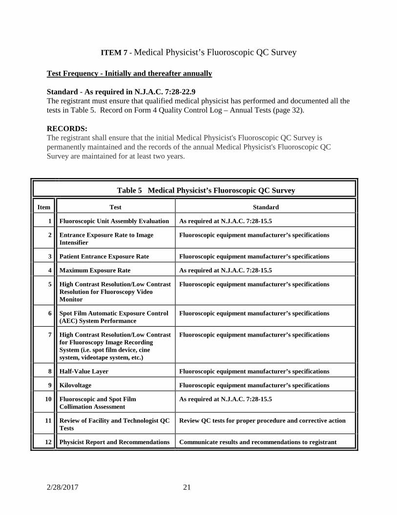
ITEM 7 - Medical Physicist’s Fluoroscopic QC Survey Test Frequency - Initially and thereafter annually Standard - As required in N.J.A.C. 7:28-22.9 The registrant must ensure that qualified medical physicist has performed and documented all the tests in Table 5. Record on Form 4 Quality Control Log – Annual Tests (page 32). RECORDS: The registrant shall ensure that the initial Medical Physicist's Fluoroscopic QC Survey is permanently maintained and the records of the annual Medical Physicist's Fluoroscopic QC Survey are maintained for at least two years.
Table 5 Medical Physicist’s Fluoroscopic QC Survey
Item
Test
Standard
1
Fluoroscopic Unit Assembly Evaluation
As required at N.J.A.C. 7:28-15.5
2
Entrance Exposure Rate to Image Intensifier
Fluoroscopic equipment manufacturer’s specifications
3
Patient Entrance Exposure Rate
Fluoroscopic equipment manufacturer’s specifications
4
Maximum Exposure Rate
As required at N.J.A.C. 7:28-15.5
5
High Contrast Resolution/Low Contrast Resolution for Fluoroscopy Video Monitor
Fluoroscopic equipment manufacturer’s specifications
6
Spot Film Automatic Exposure Control (AEC) System Performance
Fluoroscopic equipment manufacturer’s specifications
7
High Contrast Resolution/Low Contrast for Fluoroscopy Image Recording System (i.e. spot film device, cine system, videotape system, etc.)
Fluoroscopic equipment manufacturer’s specifications
8
Half-Value Layer
Fluoroscopic equipment manufacturer’s specifications
9
Kilovoltage
Fluoroscopic equipment manufacturer’s specifications
10
Fluoroscopic and Spot Film Collimation Assessment
As required at N.J.A.C. 7:28-15.5
11
Review of Facility and Technologist QC Tests
Review QC tests for proper procedure and corrective action
12
Physicist Report and Recommendations
Communicate results and recommendations to registrant
2/28/2017 22
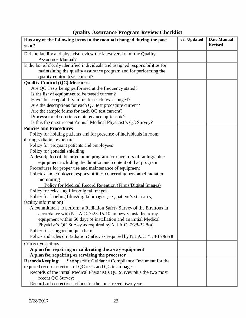
ITEM 6 - Quality Assurance Program Review Test frequency - Initially and annually thereafter Standard – As required in N.J.A.C. 7:28-22.4(a)7 The Quality Assurance Program must be reviewed in its entirety to ensure that all information is current and accurate. The review must occur annually or after any equipment or personnel change. If personnel or operating procedures change frequently, reviews should be conducted more frequently to ensure that facility’s Quality Assurance Program is maintained. Physician should review the QA program when it is initially established, after each change in personnel, equipment or policy and annually. A good time for the review is right after the Medical Physicist performs the annual QC Survey. Any changes can be reviewed with the Medical Physicist. Record on Form 4 Quality Control Log - Annual Tests (page 32). NOTE: most of the following list is taken form the requirements in N.J.A.C. 7:28-22.4 and are contained in the facility’s QA Program Manual. There is additional item listed that should be reviewed at least annually to ensure that the facility follows all applicable sections of N.J.A.C.7: 28.
2/28/2017 23
Quality Assurance Program Review Checklist
Has any of the following items in the manual changed during the past year?
√ if Updated Date Manual Revised
Did the facility and physicist review the latest version of the Quality Assurance Manual?
Is the list of clearly identified individuals and assigned responsibilities for maintaining the quality assurance program and for performing the quality control tests current?
Quality Control (QC) Measures Are QC Tests being performed at the frequency stated? Is the list of equipment to be tested current? Have the acceptability limits for each test changed? Are the descriptions for each QC test procedure current? Are the sample forms for each QC test current? Processor and solutions maintenance up-to-date?
Is this the most recent Annual Medical Physicist’s QC Survey?
Policies and Procedures Policy for holding patients and for presence of individuals in room during radiation exposure Policy for pregnant patients and employees Policy for gonadal shielding A description of the orientation program for operators of radiographic
equipment including the duration and content of that program Procedures for proper use and maintenance of equipment Policies and employee responsibilities concerning personnel radiation
monitoring Policy for Medical Record Retention (Films/Digital Images)
Policy for releasing films/digital images Policy for labeling films/digital images (i.e., patient’s statistics, facility information) A commitment to perform a Radiation Safety Survey of the Environs in
accordance with N.J.A.C. 7:28-15.10 on newly installed x-ray equipment within 60 days of installation and an initial Medical Physicist’s QC Survey as required by N.J.A.C. 7:28-22.8(a)
Policy for using technique charts Policy and rules on Radiation Safety as required by N.J.A.C. 7:28-15.9(a) 8
Corrective actions A plan for repairing or calibrating the x-ray equipment A plan for repairing or servicing the processor
Records keeping: See specific Guidance Compliance Document for the required record retention of QC tests and QC test images. Records of the initial Medical Physicist’s QC Survey plus the two most
recent QC Surveys Records of corrective actions for the most recent two years
2/28/2017 24
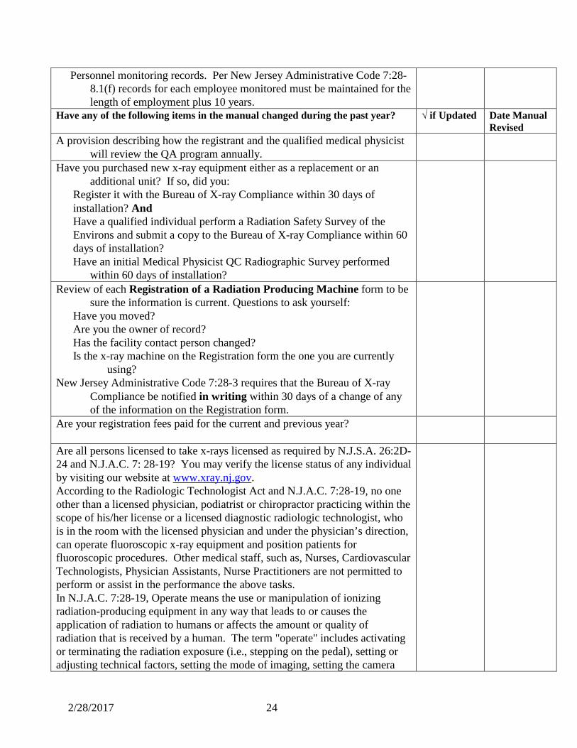
Personnel monitoring records. Per New Jersey Administrative Code 7:28-8.1(f) records for each employee monitored must be maintained for the length of employment plus 10 years.
Have any of the following items in the manual changed during the past year? √ if Updated Date Manual Revised
A provision describing how the registrant and the qualified medical physicist will review the QA program annually.
Have you purchased new x-ray equipment either as a replacement or an additional unit? If so, did you:
Register it with the Bureau of X-ray Compliance within 30 days of installation? And Have a qualified individual perform a Radiation Safety Survey of the Environs and submit a copy to the Bureau of X-ray Compliance within 60 days of installation?
Have an initial Medical Physicist QC Radiographic Survey performed within 60 days of installation?
Review of each Registration of a Radiation Producing Machine form to be sure the information is current. Questions to ask yourself:
Have you moved? Are you the owner of record? Has the facility contact person changed? Is the x-ray machine on the Registration form the one you are currently
using? New Jersey Administrative Code 7:28-3 requires that the Bureau of X-ray
Compliance be notified in writing within 30 days of a change of any of the information on the Registration form.
Are your registration fees paid for the current and previous year?
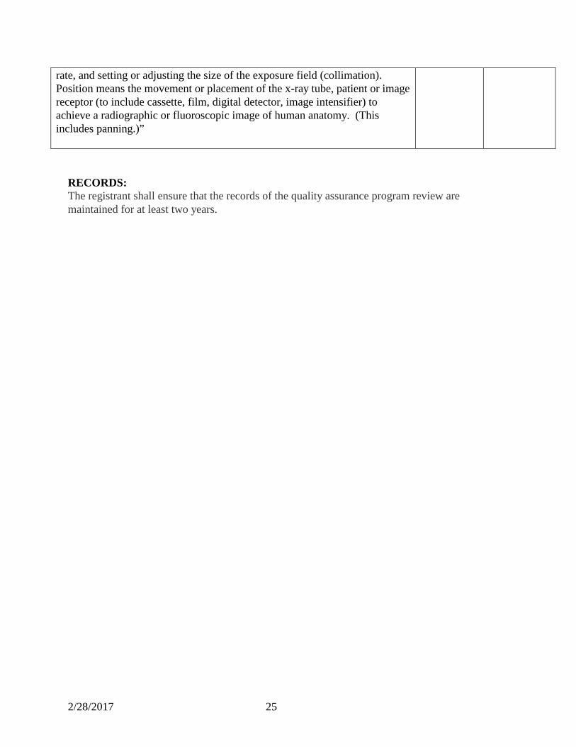
Are all persons licensed to take x-rays licensed as required by N.J.S.A. 26:2D-24 and N.J.A.C. 7: 28-19? You may verify the license status of any individual by visiting our website at www.xray.nj.gov. According to the Radiologic Technologist Act and N.J.A.C. 7:28-19, no one other than a licensed physician, podiatrist or chiropractor practicing within the scope of his/her license or a licensed diagnostic radiologic technologist, who is in the room with the licensed physician and under the physician’s direction, can operate fluoroscopic x-ray equipment and position patients for fluoroscopic procedures. Other medical staff, such as, Nurses, Cardiovascular Technologists, Physician Assistants, Nurse Practitioners are not permitted to perform or assist in the performance the above tasks. In N.J.A.C. 7:28-19, Operate means the use or manipulation of ionizing radiation-producing equipment in any way that leads to or causes the application of radiation to humans or affects the amount or quality of radiation that is received by a human. The term "operate" includes activating or terminating the radiation exposure (i.e., stepping on the pedal), setting or adjusting technical factors, setting the mode of imaging, setting the camera
2/28/2017 25
rate, and setting or adjusting the size of the exposure field (collimation). Position means the movement or placement of the x-ray tube, patient or image receptor (to include cassette, film, digital detector, image intensifier) to achieve a radiographic or fluoroscopic image of human anatomy. (This includes panning.)”
RECORDS: The registrant shall ensure that the records of the quality assurance program review are maintained for at least two years.

2/28/2017 26
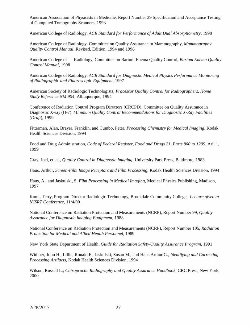
BIBLIOGRAPHY
2/28/2017 27
American Association of Physicists in Medicine, Report Number 39 Specification and Acceptance Testing of Computed Tomography Scanners, 1993 American College of Radiology, ACR Standard for Performance of Adult Dual Absorptiometry, 1998 American College of Radiology, Committee on Quality Assurance in Mammography, Mammography Quality Control Manual, Revised, Edition, 1994 and 1998 American College of Radiology, Committee on Barium Enema Quality Control, Barium Enema Quality Control Manual, 1998 American College of Radiology, ACR Standard for Diagnostic Medical Physics Performance Monitoring of Radiographic and Fluoroscopic Equipment, 1997 American Society of Radiologic Technologists; Processor Quality Control for Radiographers, Home Study Reference NM 904; Albuquerque; 1994 Conference of Radiation Control Program Directors (CRCPD), Committee on Quality Assurance in Diagnostic X-ray (H-7). Minimum Quality Control Recommendations for Diagnostic X-Ray Facilities (Draft), 1999 Fitterman, Alan, Brayer, Franklin, and Cumbo, Peter, Processing Chemistry for Medical Imaging, Kodak Health Sciences Division, 1994 Food and Drug Administration, Code of Federal Register, Food and Drugs 21, Parts 800 to 1299, Aril 1, 1999 Gray, Joel, et. al., Quality Control in Diagnostic Imaging, University Park Press, Baltimore, 1983. Haus, Arthur, Screen-Film Image Receptors and Film Processing, Kodak Health Sciences Division, 1994 Haus, A., and Jaskulski, S, Film Processing in Medical Imaging, Medical Physics Publishing, Madison, 1997 Konn, Terry, Program Director Radiologic Technology, Brookdale Community College, Lecture given at NJSRT Conference, 11/4/00 National Conference on Radiation Protection and Measurements (NCRP), Report Number 99, Quality Assurance for Diagnostic Imaging Equipment, 1988 National Conference on Radiation Protection and Measurements (NCRP), Report Number 105, Radiation Protection for Medical and Allied Health Personnel, 1989 New York State Department of Health, Guide for Radiation Safety/Quality Assurance Program, 1991 Widmer, John H., Lillie, Ronald F., Jaskulski, Susan M., and Haus Arthur G., Identifying and Correcting Processing Artifacts, Kodak Health Sciences Division, 1994 Wilson, Russell L.; Chiropractic Radiography and Quality Assurance Handbook; CRC Press; New York; 2000

2/28/2017 28
FORMS
2/28/2017 29
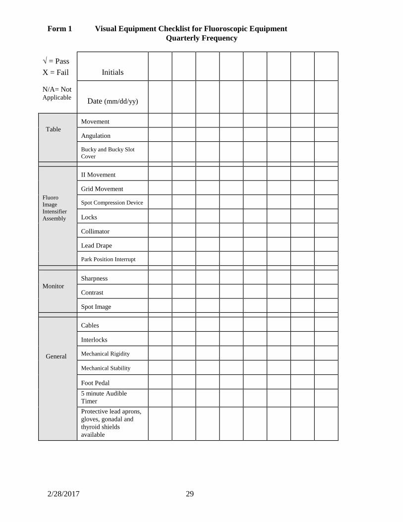
Form 1 Visual Equipment Checklist for Fluoroscopic Equipment Quarterly Frequency
√ = Pass X = Fail
Initials
N/A= Not Applicable
Date (mm/dd/yy)
Table
Movement
Angulation
Bucky and Bucky Slot Cover
Fluoro Image Intensifier Assembly
II Movement
Grid Movement
Spot Compression Device
Locks
Collimator
Lead Drape
Park Position Interrupt
Monitor
Sharpness
Contrast
Spot Image
General
Cables
Interlocks
Mechanical Rigidity
Mechanical Stability
Foot Pedal
5 minute Audible Timer
Protective lead aprons, gloves, gonadal and thyroid shields available
2/28/2017 30
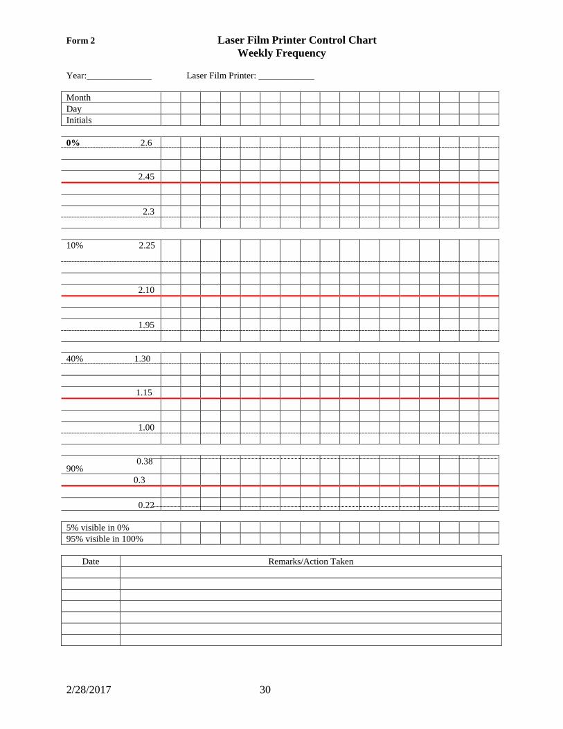
Form 2 Laser Film Printer Control Chart Weekly Frequency
Year:______________ Laser Film Printer: ____________ Month Day Initials 0% 2.6 2.45 2.3 10% 2.25
2.10 1.95 40% 1.30 1.15 1.00
90% 0.38
0.3 0.22 5% visible in 0% 95% visible in 100%
Date Remarks/Action Taken
2/28/2017 31
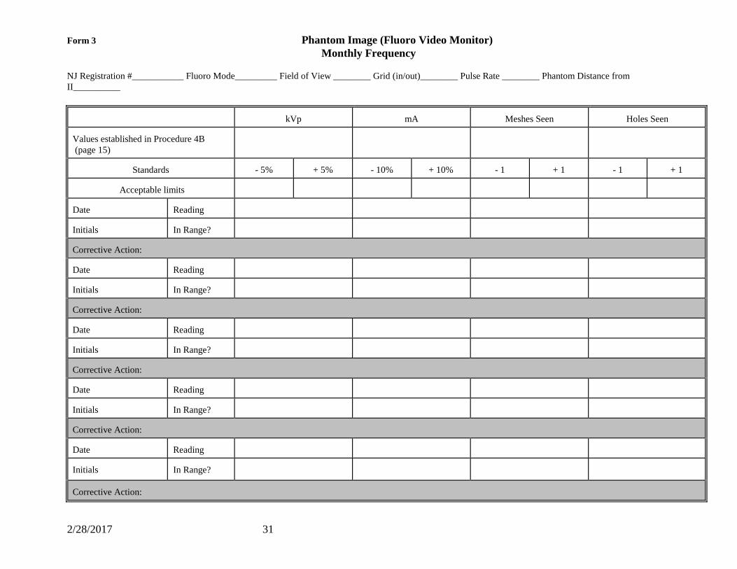
Form 3 Phantom Image (Fluoro Video Monitor) Monthly Frequency
NJ Registration #___________ Fluoro Mode_________ Field of View ________ Grid (in/out)________ Pulse Rate ________ Phantom Distance from II__________
kVp
mA
Meshes Seen
Holes Seen
Values established in Procedure 4B (page 15)
Standards
- 5%
+ 5%
- 10%
+ 10%
- 1
+ 1
- 1
+ 1
Acceptable limits
Date
Reading
Initials
In Range?
Corrective Action: Date
Reading
Initials
In Range?
Corrective Action: Date
Reading
Initials
In Range?
Corrective Action: Date
Reading
Initials
In Range?
Corrective Action: Date
Reading
Initials
In Range?
Corrective Action:
2/28/2017 32
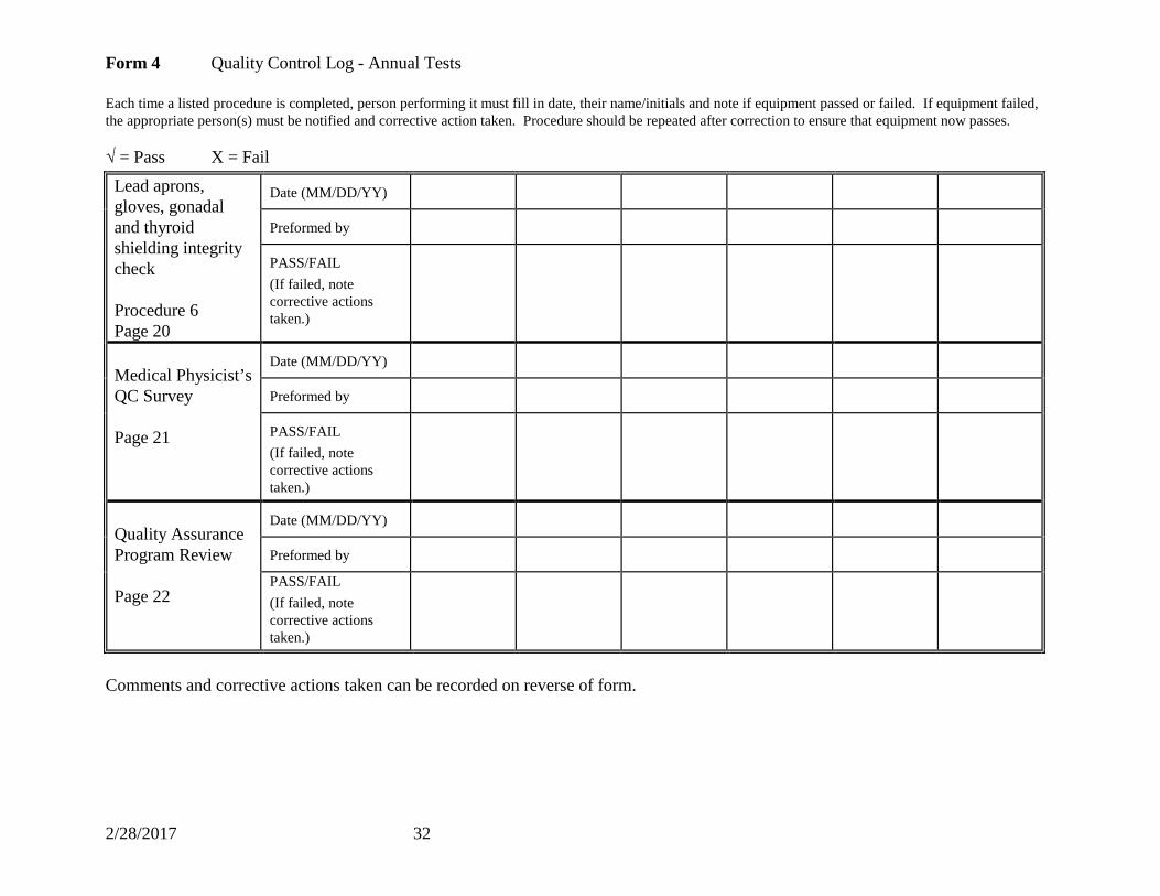
Form 4 Quality Control Log - Annual Tests Each time a listed procedure is completed, person performing it must fill in date, their name/initials and note if equipment passed or failed. If equipment failed, the appropriate person(s) must be notified and corrective action taken. Procedure should be repeated after correction to ensure that equipment now passes. √ = Pass X = Fail Lead aprons, gloves, gonadal and thyroid shielding integrity check Procedure 6 Page 20
Date (MM/DD/YY)
Preformed by
PASS/FAIL (If failed, note corrective actions taken.)
Medical Physicist’s QC Survey Page 21
Date (MM/DD/YY)
Preformed by
PASS/FAIL (If failed, note corrective actions taken.)
Quality Assurance Program Review Page 22
Date (MM/DD/YY)
Preformed by
PASS/FAIL (If failed, note corrective actions taken.)
Comments and corrective actions taken can be recorded on reverse of form.