Embed Size (px)
Citation preview

Note: In accordance with the policy of TSUBAKIMOTO CHAIN CO. to constantly improve its products, the specifications in this catalog are subject to change without notice.Catalog No.07164 ©2011/10 TSUBAKIMOTO CHAIN CO. Printed in Japan 3,000
Complies with RoHSComplies with RoHSComplies with RoHS
NEW
NEP CHAINSUPERIOR CORROSION RESISTANCE
TSUBAKI
Patent Pending

NEP Chain is a tough coated chain with two different optimized coatings for its different parts. (See below.) These special coatings have high corrosion resistance and protect the chain from corrosive environments.
NEP Surface Coating Structure
No rust appeared on the NEP Chain even after 700hrs in a salt spray test. (JIS-Z-2371)
Superior Corrosion Resistance
In-house salt spray test results of NP, WP, DP, and NEP Chains
50 hours 300 hours 600 hours 700 hoursNO RUST
NP Chain WP Chain DP Chain NEP Chain
■Pin
■ Bush ■ Roller
■Plate
Triple Layer Special Surface Coating Special Surface Coating
1 2
Tsubaki is eliminating all surface coated chains that contain designated hazardous chemicals* and working towards reducing our environmental load.* Hexavalent chromium, cadmium, lead, etc.
In order to reduce our environmental
load, Tsubaki has developed a
unique eco-friendly surface coating,
featured on our new NEP Chain.
NEP Chain (New Environmental
Plating Chain) has superior corrosion
resistance than our WP or DP Chains,
reducing its load on the environment.
Special Coating
Top Coating
Chain Chain
Special Coating
2.3 times the anti-rust performance of WP Chain and 1.4 times that of DP!
NEP
DP
WP
1.4 times
2.3 times
Features superior comprehensive anti-corrosion properties for outdoor use.
Superior Corrosion Resistance
The individual parts of NEP Chains are surface treated - and unlike chains treated after assembly, even the inner parts of NEP Chains are treated.
Deviation-free Parts Processing Control
Peeling flakes from WP, DP, and NEP ChainsThe coating on chain rollers peels when they engage the sprocket. However, the peeling from NEP Chains is finer than DP Chains. (Same as WP Chain)
Peeling
WP Chain DP Chain NEP Chain
Chain strength (part hardness) is unaffected thanks to low treatment temperatures.Thus, NEP Chains have the same tensile strength and allowable load as our standard Roller Chains.
No Strength Reduction
MinimumTensile Strength
MaximumAllowable Load
StandardChain NEP Chain
Zinc ChromiumCompound NP Chain
StainlessSteel
17.7{1800}
17.7{1800}
16.6*{1690}
17.7{1800}
----
3.63{370}
3.63{370}
Ref: With RS40 (Drive Chain)*Competitor Average Tensile Strength
Unit: kN {kgf}
---- 3.04{310}
0.44{45}
NEP Chains use no harmful hexavalent chromium in their anti-rust surface treatment, nor any other hazardous substances such as lead, cadmium, mercury, or arsenic. NEP Chain complies with RoHS.
Environmentally Friendly
RoHS (Restriction of the Use of Certain Hazardous Substances in Electrical Equipment)RoHS is a directive issue by the European Union limiting the use of specified hazardous substances in electronics or electrical equipment.
Complies with RoHSComplies with RoHS

NEP lives up to the expectations of customers in corrosive environments.*Applications are based on actual DP results
Product Digest and Applications
3 4
RS35-1--- RS160-1RS40-2--- RS100-2
NEP ANSI Drive SeriesChain Sizes
RS35-1--- RS100-1(Unit Stock)
Stocked Products
Application: Drive for car wash roller conveyor, brush, and blowerEnvironment: Sprayed with water and cleaning solution
In Roller Conveyors For Car WashApplication: Lifting chain for stacker cranes in mushroom cultivationEnvironment: High temperature/humidity
In Automated Warehouses
Application: Drive for Roller coveyors for pin case cleaningEnvironment: Sprayed with cleaning solution
In Roller Conveyors For Case CleaningApplication: Drive for flow conveyorEnvironment: Frequent exposure to sea spray
In Outdoor Conveyor Drives (Coastal Environments)
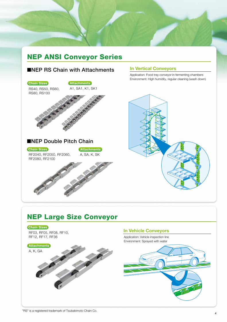
■NEP RS Chain with Attachments
NEP ANSI Conveyor Series
RS40, RS50, RS60, RS80, RS100
A1, SA1, K1, SK1
AttachmentsChain Sizes
■NEP Double Pitch Chain
RF2040, RF2050, RF2060, RF2080, RF2100
A, SA, K, SK
AttachmentsChain Sizes
Application: Food tray conveyor in fermenting chambersEnvironment: High humidity, regular cleaning (wash down)
In Vertical Conveyors
"RS" is a registered trademark of Tsubakimoto Chain Co.
RF03, RF05, RF08, RF10, RF12, RF17, RF36
NEP Large Size Conveyor
A, K, GA
Application: Vehicle inspection lineEnvironment: Sprayed with water
In Vehicle ConveyorsChain Sizes
Attachments
NEP lives up to the expectations of customers in corrosive environments.*Applications are based on actual DP results
Product Digest and Applications
3 4
RS35-1--- RS160-1RS40-2--- RS100-2
NEP ANSI Drive SeriesChain Sizes
RS35-1--- RS100-1(Unit Stock)
Stocked Products
Application: Drive for car wash roller conveyor, brush, and blowerEnvironment: Sprayed with water and cleaning solution
In Roller Conveyors For Car WashApplication: Lifting chain for stacker cranes in mushroom cultivationEnvironment: High temperature/humidity
In Automated Warehouses
Application: Drive for Roller coveyors for pin case cleaningEnvironment: Sprayed with cleaning solution
In Roller Conveyors For Case CleaningApplication: Drive for flow conveyorEnvironment: Frequent exposure to sea spray
In Outdoor Conveyor Drives (Coastal Environments)
■NEP RS Chain with Attachments
NEP ANSI Conveyor Series
RS40, RS50, RS60, RS80, RS100
A1, SA1, K1, SK1
AttachmentsChain Sizes
■NEP Double Pitch Chain
RF2040, RF2050, RF2060, RF2080, RF2100
A, SA, K, SK
AttachmentsChain Sizes
Application: Food tray conveyor in fermenting chambersEnvironment: High humidity, regular cleaning (wash down)
In Vertical Conveyors
"RS" is a registered trademark of Tsubakimoto Chain Co.
RF03, RF05, RF08, RF10, RF12, RF17, RF36
NEP Large Size Conveyor
A, K, GA
Application: Vehicle inspection lineEnvironment: Sprayed with water
In Vehicle ConveyorsChain Sizes
Attachments

5
L L
RS35-NEP --- RS60-NEP RS80-NEP --- RS160-NEP
h H
P P
T TW
L1
L2
D R C
L1
L2
RS50-NEP-1No. of Strands
RS35-NEP-1RS40-NEP-1RS40-NEP-2RS50-NEP-1RS50-NEP-2RS60-NEP-1RS60-NEP-2RS80-NEP-1RS80-NEP-2
RS100-NEP-1RS100-NEP-2RS120-NEP-1RS140-NEP-1RS160-NEP-1
RS35-NEP-1RS40-NEP-1RS40-NEP-2RS50-NEP-1RS50-NEP-2RS60-NEP-1RS60-NEP-2RS80-NEP-1RS80-NEP-2
RS100-NEP-1RS100-NEP-2RS120-NEP-1RS140-NEP-1RS160-NEP-1
TSUBAKI Chain Number
Plate PinRoller Dia.(Bushing Dia.)
R
(5.08)
7.92
10.16
PitchP
9.525
12.70
15.875
Inner Widthof Inner Link
W
4.78
7.95
9.53
ThicknessT
1.25
1.5
2.0
HeightH
9.0
12.0
15.0
Heighth
7.8
10.4
13.0
DiameterD
3.59
3.97
5.09
L1+L2
12.718.232.622.340.5
L1
5.85 8.2515.4510.3 19.35
L2
6.85 9.9517.1512.0 21.15
Offset Pin LengthL
13.518.233.522.641.8
TransversePitch
C
--
14.4-
18.1
11.91
15.88
19.05
19.05
25.40
31.75
12.70
15.88
19.05
2.4
3.2
4.0
18.1
24.1
30.1
15.6
20.8
26.0
5.96
7.94
9.54
27.650.535.564.842.6
12.8524.2516.2530.9 19.75
14.7526.2519.2533.9 22.85
28.252.638.267.545.7
-22.8
-29.3
-
22.2325.4028.58
38.1044.4550.80
25.4025.4031.75
4.85.66.4
36.242.248.2
31.236.441.6
11.1112.7114.29
78.553.858.668.7
37.7 24.9 26.9 31.85
40.8 28.9 31.7 36.85
81.557.863.473.6
35.8---
TSUBAKI Chain Number
Minimum Tensile StrengthkN{kgf}
9.81{ 1000}
Maximum AllowableLoad
kN{kgf}
2.16 { 220} 17.7 { 1800} 3.63 { 370} 35.3 { 3600} 6.18 { 630} 28.4 { 2900} 6.37 { 650} 56.9 { 5800} 10.7 {1100} 40.2 { 4100} 8.83 { 900} 80.4 { 8200} 15.0 {1530} 71.6 { 7300} 14.7 {1500}143 {14600} 25.0 {2550}107 {10900} 22.6 {2300}214 {21800} 38.3 {3910}148 {15100} 30.4 {3100}193 {19700} 40.2 {4100}255 {26000} 53.0 {5400}
ApproximateMasskg/m
0.33 0.64 1.27 1.04 2.07
Links per Unit
320
240
192
1.53 3.04 2.66 5.27 3.99
160
120
96 7.85 5.93 7.4910.10
80 68 60
1. Maximum allowable load is 65% of the above values when using a one-pitch offset link.2. RS35-NEP is a bushed chain.3. Multi-strand RS35-NEP unavailable.4. 2POL unavailable.
■Chain Numbering Example
NEP ANSI Drive Series
■Connecting Link: Spring Clip: RS35-NEP − RS60-NEP Cotter Pin: RS80-NEP − RS160-NEP ✽Riveting is standard on all NEP Chains.
Chain Number
NEP Specification Code
■Operating Temperature Range:
■Precautions on Use:
■BS/DIN Drive Series is available. Please contact TSUBAKI representative.
■Selection/Handling:
-10˚C − 150˚C(Use a high temperature lubricant when using above 60˚C. Contact a Tsubaki representative when using in temperatures beyond the ranges given.)
Refer to the Tsubaki Drive Chains catalog for information on selection and handling.Catalog No.120
Electrical corrosion may occur when steel chains are used with stainless steel sprockets, promoting premature wear. Avoid mutual contact as much as possible. In-house tests have shown that the middle links of multi-strand chains have slightly less corrosion resistance than with single-strand chains.

6
X XX
O N
O N
O N
O N
CS
X2
C
X2
CS
X2
XS
C1 X
S
C1
L2
L 1
T
P P
P P
P P
P P
R
L2
L1
T
L2
L1
T
L2
L1
T
HW
T
WT
T
WT
WT
T
H
A1 Attachment
SA1 Attachment
K1 Attachment
SK1 Attachment
DR
D
R
D
R
D
RS50-NEP-1L A1
RS40-NEPRS50-NEPRS60-NEPRS80-NEP
RS100-NEP
TSUBAKI Chain Number
Plate PinRollerDiameter
R
7.9210.1611.9115.8819.05
PitchP
12.70 15.87519.05 25.40 31.75
Inner Width of Inner Link
W
7.95 9.5312.7015.8819.05
ThicknessT
1.52.02.43.24.0
HeightH
12.015.018.124.130.1
DiameterD
3.975.095.967.949.54
L1
8.2510.3 12.8516.2519.75
L2
9.9512.0 14.7519.2522.85
2.65 { 270} 4.31 { 440} 6.28 { 640}10.7 {1090}17.1 {1740}
ApproximateMasskg/m
MaximumAllowable Load
kN{kgf}
14.7 {1500}23.5 {2400}35.3 {3600}60.8 {6200}93.2 {9500}
MinimumTensile Strength
kN{kgf}
0.641.041.532.663.99
�Operating Temperature Range : -10˚C − 150˚C(Lubricate with a high temperature lubricant when using above 60˚C. Consult Tsubaki when using in temperatures beyond the ranges given.)
�Selection/Handling: Refer to the TSUBAKI Chain Products General Catalog (Catalog No. CHAIN 001-1) for information on selection and handling.
�Precautions on Use:Electrical corrosion may occur when steel chains are used with stainless steel sprockets, promoting premature wear. Avoid mutual contact as much as possible.
�BS/DIN Conveyor Series is available. Please contact TSUBAKI representative.
NEP ANSI Conveyor Series
�Connecting Link Type: Spring Clip: RS40-NEP − RS60-NEP Cotter Pin: RS80-NEP − RS100-NEP �All other pins are riveted (RP), regardless of whether attachment is present or not.
Chain Number Attachment Type
Attachment SpacingNEP Specification
RS40-NEPRS50-NEPRS60-NEPRS80-NEP
RS100-NEP1. Made-to-order.2. O is marginally smaller.
TSUBAKI Chain Number
C C1 N O S X X2 X2
Attachments
A/SA Attachments K/SK Attachments
12.7 15.9 19.0525.4 31.75
12.715.918.324.631.8
9.512.715.919.125.4
3.65.25.26.88.7
8.010.311.915.919.8
17.823.428.236.644.9
17.823.428.236.644.9
17.4023.0526.8535.4544.00
0.0020.0030.0070.0130.026
0.0040.0060.0140.0260.052
Links per Unit
240192160120 96
kgMass per Attachment
�Chain Numbering Example
6

7
PP
HL1
T
TW
L2
R1
D
S Roller
A1 Attachment
X2
CT
S
N
P P
XX X2
CT
S
OONK
P P
A2 Attachment
PP
NO1
C1 X
S
PP
NK TO
C2 X
S
SA1 Attachment SA2 Attachment
PP
HL 1
T
TW
L2
R2
D
XX
X2
X2
X2
X2
CC
T
O N
XX
CC
T
OKN
R Roller
SP P
S
P P
PP
NO1
C1 X
S
KN
TO
C2 X
S
K1 Attachment K2 Attachment
SK1 Attachment SK2 Attachment
PP
L D
Offset Link (S Roller)
L
P
H
P
H
Offset Link (R Roller)
D
RF2050R-NEP-1L A2Attachment Type
Attachment Spacing
RF2040-NEPRF2050-NEPRF2060-NEPRF2080-NEPRF2100-NEP
TSUBAKI Chain Number
RollerType Pitch
PS Roller
R1
R RollerR2
Inner Widthof Inner Link
WThickness
THeight
HDia.D L1
OffsetPin Length
LS Roller R Roller
Roller Dia. Plate Pin Approximate Mass kg/m Minimum TensileStrengthkN{kgf}
MaximumAllowable Load
kN{kgf}
25.4031.7538.1050.8063.50
S, R
7.9210.1611.9115.8819.05
15.8819.0522.2328.5839.69
7.95 9.5312.7015.8819.05
1.52.03.24.04.8
12.015.017.223.028.6
3.975.095.967.949.54
8.2510.3014.5518.3021.80
L2
9.9512.0 16.5520.9024.50
18.222.631.541.949.0
0.510.841.512.413.54
0.871.302.193.525.80
14.7 {1500}23.5 {2400}35.3 {3600}60.8 {6200}93.2 {9500}
2.65 { 270} 4.31 { 440} 6.28 { 640}10.7 {1090}17.1 {1740}
RF2040-NEPRF2050-NEPRF2060-NEPRF2080-NEPRF2100-NEP
TSUBAKIChain Number
C C1 C2 K N O O1 S T X X2 XS
Attachments Mass per Attachmentkg
A/SA Attachment K/SK Attachment
11.114.317.522.228.6
12.7 15.9 21.4527.8 33.35
13.615.919.125.431.8
9.511.914.319.123.8
19.123.828.638.147.6
3.65.25.26.88.7
5.2 6.8 8.710.314.3
9.111.114.719.123.4
1.52.03.24.04.8
19.324.231.540.749.9
17.622.028.236.644.9
19.824.630.640.550.4
0.0030.0060.0170.0320.060
0.0060.0120.0340.0640.120
120 96 80 60 48
NEP ANSI Double pitch conveyor Series
�Connecting Link Type: Spring Clip: RF2040-NEP − RF2060-NEP Cotter Pin: RF2080-NEP, RF2100-NEP �All other pins are riveted (RP), regardless of whether attachment is present or not. �Sizes over RF2080-NEP have cotter pins on both ends of the offset link.
Chain Number
Roller Type S, R
NEP Specification
■Chain Numbering Example
Linksper Unit
1. Made-to-order.2. O, O1 dimensions are marginally smaller.�Operating Temperature Range : -10˚C − 150˚C
(Lubricate with a high temperature lubricant when using above 60˚C. Consult Tsubaki when using in temperatures beyond the ranges given.)�Selection/Handling:
Refer to the TSUBAKI Chain Products General Catalog (Catalog No. CHAIN 001-1) �Precautions on Use:
Electrical corrosion may occur when steel chains are used with stainless steel sprockets, promoting premature wear. Avoid mutual contact as much as possible.

8
RF03100F-DT-NEP-1L A2
R Roller
L1+
L2
L2
E
TW
T
L1
P P
H
L1+
L2
L2
TW
T
L1
S, M, N RollerH
PP
E
eZL1+
L2
L2
TH
WT
L1
PP
Sprocket Center
Chain Center
F Roller
R
D
R
D
R
F
D
Chain Number
Roller Type R, F, S, M
NEP Specification
Chain Material
1. Made-to-order
�Refer to pg. 9 for attachment dimensions.
NEP Large Size Conveyor
RF03075-NEPRF03100-NEPRF05075-NEPRF05100-NEPRF05125-NEPRF05150-NEPRF08125-NEPRF08150-NEPRF10100-NEPRF10125-NEPRF10150-NEPRF12200-NEPRF12250-NEPRF17200-NEPRF17250-NEPRF17300-NEPRF26200-NEPRF26250-NEPRF26300-NEPRF26450-NEPRF36250-NEPRF36300-NEPRF36450-NEPRF36600-NEP
Roller Dimensions Plate Pin Approximate Mass kg/m StandardSeries Ave.
TensileStrengthkN{kgf}
RollerType
R, F, SR, F, S
SR, F, SR, F, SR, F, SR, F, SR, F, SR, S, MR, F, S, MR, F, S, MR, F, S, MR, F, S, MR, F, S, MR, F, S, MR, F, S, M
R, F, S, MR, F, S, MR, F, S, M
S, M
S, M
R, F, S, MR, F, S, MR, F, S, M
PitchP
75100 75100125150125150100125150200250200250300200250300450250300450600
R Roller
31.8
40
44.5
50.8
65
80
-
100
-
125
ContactWidth
EDiaR
15.5
19
23
27
32
44
-
50
-
56
DiaR
31.8
40
44.5
50.8
65
80
-
100
-
125
FlangeDia.
F
ContactWidth
E
CenterDifference
e
42
50
55
65
80
100
-
125
-
150
F Roller
12
14
18
20
24
34
-
38
-
42
S Roller
Dia.R
1.8
2.5
2.5
3
4
5
-
6
-
7
Z
4.3
4.5
6.5
7
8
12
-
13
-
14
15.9
22.2
22.2
29
34.9
40.1
44.5
50.8
-
-
25.4
31.8
38.1
44.5
50.8
57.2
InnerWidth
of InnerLink
W
16.1
22
27
30
37.1
51.4
57.2
66.7
22
32
28.6
38.1
44.5
50.8
63.5
76.2
Thickness
TDia.
DHeight
H
3.2
4.5
6.3
6.3
7.9
9.5
9.5
12.7
8.0
11.3
11.3
14.5
15.9
19.1
22.2
25.4
38
53.5
65.5
69
83.5
109.5
116.5
146
18
25
31
33
40.5
51.5
55.5
68
L2L1L1+L2
20
28.5
34.5
36
43
58
61
78
RRoller
1720
10.411.6 8.0 8.710.0 5.6 5.9 4.2 4.5 5.2
- 2.4 2.8
16-
2623
-19
403228
FRoller
2.9 2.5
- 5.4 4.6 4.4 6.2 5.8
- 9.0 8.312.110.8211816-
272419-
423329
SRoller
1.64.33.83.43.34.24.07.06.35.98.37.8121111161514
1.8
1325232119
--------
7.36.56.18.68.01312111716151326242120
29{ 3000}
69{ 7000}
78{ 8000}
113{11500}
186{19000}
245{25000}
314{32000}
476{48500}
Dia.R
MN RollerM
N
�Chain Numbering Example
Attachment Type
Attachment Spacing
TSUBAKI Chain Number
�Operating Temperature Range : -20˚C − 200˚C
�Selection/Handling: Refer to the TSUBAKI Chain Products General Catalog (Catalog No. CHAIN 001-1)
�Precautions on Use: Electrical corrosion may occur when steel chains are used with stainless steel sprockets, promoting premature wear. Avoid mutual contact as much as possible.
Roller

O
O
XX
A2 (welded) Attachment
A3 (welded) Attachment
Angle
Angle
N
X
A2 Attachment
PP
OKN
2C2X
S
T
K2 Attachment
A1 Attachment
ON
2C2X
K1 Attachment
P P
T
S
GA2 Attachment
P P
90°
T1
Q1 Q2
K1
KN
P
SC
N
P
SC
K/2 K/2
K OON
CX
C
A
O1
RF03075-NEPRF03100-NEPRF05075-NEPRF05100-NEPRF05125-NEPRF05150-NEPRF08125-NEPRF08150-NEPRF10100-NEPRF10125-NEPRF10150-NEPRF12200-NEPRF12250-NEPRF17200-NEPRF17250-NEPRF17300-NEPRF26200-NEPRF26250-NEPRF26300-NEPRF26450-NEPRF36250-NEPRF36300-NEPRF36450-NEPRF36600-NEP
1. The mass of the A Attachments shown in the table are per attachment (kg). For K Attachments, multiply by two.
Attachment (A, K) Attachment (GA2)Max. Bolt Length
Matching Standard Attachments with Roller Type AAttachment
Masskg
T
3.2
4.5
6.3
6.3
7.9
9.5
9.5
-
10
S
20
22
28
28
38
45
55
-
70
C
30
35
50
50
60
75
80
-
100
X
46
47
64
67
79
100
108
123.5-
160
K
30 40 30 40 50 60 50 60 40 50 60 80125 80125180 80125180280
-100280360
N
55 65 55 65 75 85 80 90 70 80 90120170120170220120170220320
-160330410
O
10
10
12
12
15
15
15
-
19
Bolt
M8
M8
M10
M10
M12
M12
M12
-
M16
K1
30 50
- 40 50 60
- 60 30 40 60 80125 70110150
-
140220
-
220300
T1
3.2
-
4.5
-6.3
6.3
7.9
9.5
-
9.5
-
12.7
Q1
15.5
-
21
-27
28.5
35.5
45.5
-
48.5
-
60
Q2
11.5
-
15.5
-20
21.5
26.5
35
-
38
-
46
A
13.5
-
15
-20
20
26
26
-
26
-
32
O1
8
-
10
-12
12
15
15
-
15
-
19
Bolt
M6
-
M8
-M10
M10
M12
M12
-
M12
-
M15
OuterLink
26
-
36
-45
49
63
81
-
88
-
105
InnerLink
19
-
26
-31
35
45
61
-
67
-
75
A1K1
R, F, SR, F, S
SR, F, SR, F, SR, F, SR, F, SR, F, SR, S, MR, F, S, MR, F, S, MR, F, S, MR, F, S, MR, F, S, MR, F, S, M
---------
A2K2
R, F, S, MR, F, S, MR, F, S, MR, F, S, MR, F, S, MR, F, S, MR, S, MR, F, S, MR, S, MR, F, SR, F, SR, F, S
SR, F, SR, F, S
R, F, S, MS, M
R, F, S, MR, F, S, M
--
---
A2(welded)
-------------------
------------------
R, F, S, M-
R, F, S, MR, F, S, MR, F, S, M
A3(welded)
-
R, F, S, M--
R, F, S, MR, F, S, M
GA2
R, SR, S
-R, SR, F, SR, F, S
-R, F, S
S, MR, S, MR, F, S, MR, F, S, MR, F, S, MR, F, S, MR, F, S, MR, F, S, M
--
R, F, S, MR, F, S, M
--
R, F, S, MR, F, S, M
0.060.070.060.070.080.100.190.230.160.180.200.440.610.640.881.260.741.011.343.19
- 2.4 4.9 6.1
NEP Large Size Conveyor
�Refer to the dimensional table on pg. 8 for P (Pitch) dimensions.
TSUBAKI Chain Number
A1/K1 Attachment: Attachments may have three holes. In this case, use the middle hole.
A/K Attachment: Consult a Tsubaki representative if you are using guides on the attachment side.
9

10
Note: In accordance with the policy of TSUBAKIMOTO CHAIN CO. to constantly improve its products, the specifications in this catalog are subject to change without notice.Catalog No.07164 ©2011/10 TSUBAKIMOTO CHAIN CO. Printed in Japan 3,000
Complies with RoHSComplies with RoHSComplies with RoHS
NEW
NEP CHAINSUPERIOR CORROSION RESISTANCE
TSUBAKI
Patent Pending