Embed Size (px)
Citation preview
JUNIOR hACk ATTACk™ SOfTbALL PITChINg MAChINeSports Attack, LLC. • 800-717-4251 • www.sportsattack.com 11
COMPONeNT RePLACeMeNTtHROWInG WHeeL RePLACeMent 1. Turn the on/off switch “OFF” and unplug the power cord. For the bottom throwing wheel, remove three (3) bolts holding the ball chute to the main casting.
2. Hold the wheel so that it cannot move. Turn the keyway retaining bolt counter-clockwise using a box-end wrench. SUGGESTION: If the bolt is too tight, give the opposite end of the wrench a series of light taps with a hammer making sure the wrench remains on the bolt.
3. Remove the bolt and washers.
4. Work the wheel off of the motor shaft. Be sure to catch the key as it is freed from the keyway.
5. Ball throwing wheels are machine balanced. Small holes in the side of the wheel are applied at the factory and are normal. A slight wobble is normal.
Reassemble in reverse order. a. Install wheel to motor shaft with key slots aligned. b. Be sure the key is in place, and inserted so that it is flush with the boss at the wheel center. c. Be sure the washer and lock washer are installed in the right order, and that the keyway retaining bolt is tightened. d. Test the wheel by spinning it by hand and making sure that it spins freely without excessive wobble before turning the unit “ON”. e. Be sure the wheel guard is properly and securely reinstalled.
MOtOR RePLACeMent 1. Turn the on/off switch “OFF” and unplug the power cord.
2. Remove the throwing wheel (see above).
3. Remove four (4) screws holding controller into main casting. Note the position of the motor wires on the controller, then disconnect the wires. See Figure 12 on page 12.
4. Note the routing of the motor wires. Loosen any wire clamps.
5. Remove four (4) bolts holding the motor to the main casting. See Figures 9 & 10 on page 11.
Reassemble in reverse order.
Component R
eplacem
ent
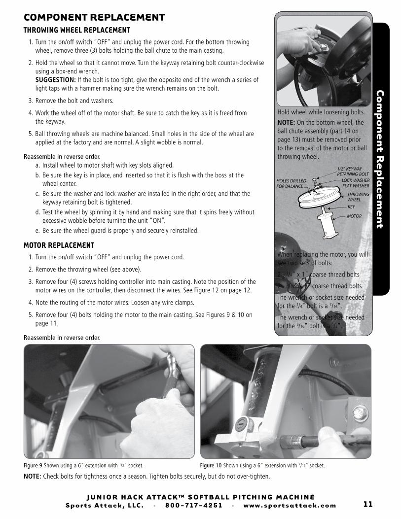
NOTE: On the bottom wheel, the ball chute assembly (part 14 on page 13) must be removed prior to the removal of the motor or ball throwing wheel.
Hold wheel while loosening bolts.
NOTE: Check bolts for tightness once a season. Tighten bolts securely, but do not over-tighten.
When replacing the motor, you will see two sets of bolts:
2 - 1/4” x 1” coarse thread bolts
2 - 5/16” x 1” coarse thread bolts
The wrench or socket size needed for the 1/4” bolt is a 7/16”.
The wrench or socket size needed for the 5/16” bolt is a 1/2”.
Figure 9 Shown using a 6” extension with 1/2” socket. Figure 10 Shown using a 6” extension with 7/16” socket.
1/2” KEYWAY RETAINING BOLT
LOCK WASHERFLAT WASHER
KEY
MOTOR
THROWINGWHEEL
HOLES DRILLEDFOR BALANCE
JUNIOR hACk ATTACk™ SOfTbALL PITChINg MAChINeSports Attack, LLC. • 800-717-4251 • www.sportsattack.com 12
COMPONeNT RePLACeMeNT (cont’d)COntROLLeR RePLACeMent 1. Turn the on/off switch “OFF” and unplug the power cord.
2. Remove four screws holding controller faceplate into main casting. Note the position of the main power and motor wires on the controller, then disconnect the wires. See Figure 12 on page 12 for the three motor wires. See Figure 13 on page 12 for the main power cord wires.
Reassemble in reverse order. Be sure wires are correctly reinstalled. Motor wire connectors are different sizes. Be sure they are installed on the correct size terminal. See Figure 12 for the motor wires and Figure 13 for the power cord wire.
Component R
eplacem
ent
Figure 11 Wiring diagram from the control board side.
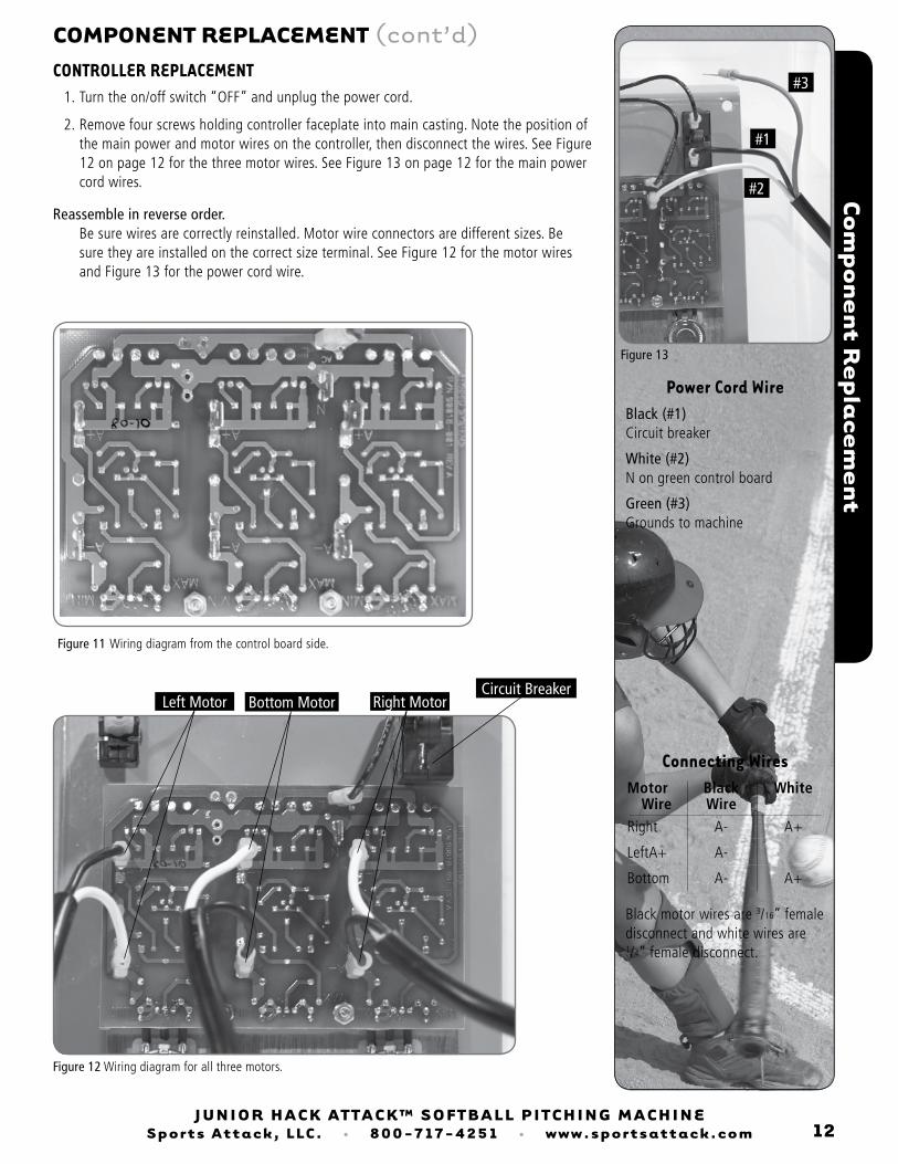
Figure 12 Wiring diagram for all three motors.
Right MotorCircuit Breaker
Bottom MotorLeft Motor
Power Cord Wire
Connecting Wires Motor Black White Wire Wire Right A- A+
Left A+ A-
Bottom A- A+
Black (#1) Circuit breaker
White (#2) N on green control board
Green (#3) Grounds to machine
Black motor wires are 3/16” female disconnect and white wires are 1/4” female disconnect.
#3
#1
#2
Figure 13