Embed Size (px)
Citation preview
ARL-TR-9016 ● SEP 2020
Composite Living Hinges for Robotic Applications by Colin Rowbottom, Lauren A Moore, and Daniel M Baechle
Approved for public release; distribution is unlimited.
NOTICES
Disclaimers
The findings in this report are not to be construed as an official Department of the Army position unless so designated by other authorized documents.
Citation of manufacturer’s or trade names does not constitute an official endorsement or approval of the use thereof.
Destroy this report when it is no longer needed. Do not return it to the originator.
ARL-TR-9016 ● SEP 2020
Composite Living Hinges for Robotic Applications Colin Rowbottom, Lauren A Moore, and Daniel M Baechle Weapons and Materials Research Directorate, CCDC Army Research Laboratory
Approved for public release; distribution is unlimited.
ii
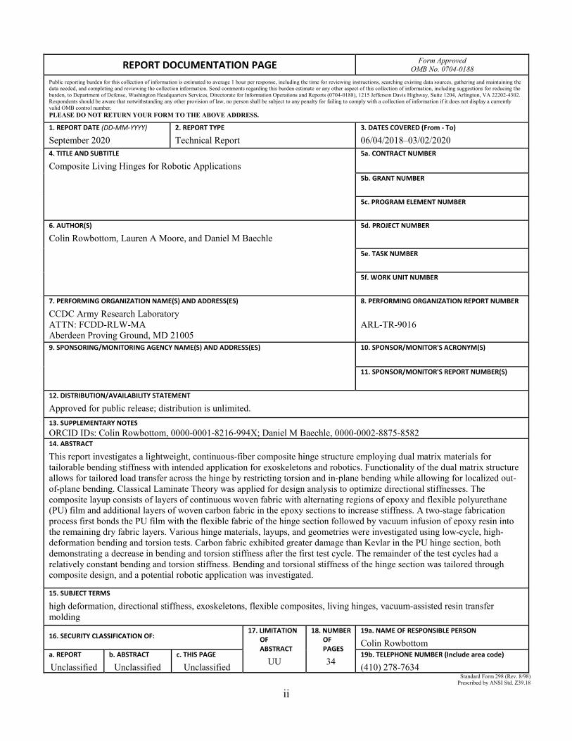
REPORT DOCUMENTATION PAGE Form Approved OMB No. 0704-0188
Public reporting burden for this collection of information is estimated to average 1 hour per response, including the time for reviewing instructions, searching existing data sources, gathering and maintaining the data needed, and completing and reviewing the collection information. Send comments regarding this burden estimate or any other aspect of this collection of information, including suggestions for reducing the burden, to Department of Defense, Washington Headquarters Services, Directorate for Information Operations and Reports (0704-0188), 1215 Jefferson Davis Highway, Suite 1204, Arlington, VA 22202-4302. Respondents should be aware that notwithstanding any other provision of law, no person shall be subject to any penalty for failing to comply with a collection of information if it does not display a currently valid OMB control number. PLEASE DO NOT RETURN YOUR FORM TO THE ABOVE ADDRESS.
1. REPORT DATE (DD-MM-YYYY)
September 2020 2. REPORT TYPE
Technical Report 3. DATES COVERED (From - To)
06/04/2018–03/02/2020 4. TITLE AND SUBTITLE
Composite Living Hinges for Robotic Applications 5a. CONTRACT NUMBER
5b. GRANT NUMBER
5c. PROGRAM ELEMENT NUMBER
6. AUTHOR(S)
Colin Rowbottom, Lauren A Moore, and Daniel M Baechle 5d. PROJECT NUMBER
5e. TASK NUMBER
5f. WORK UNIT NUMBER
7. PERFORMING ORGANIZATION NAME(S) AND ADDRESS(ES)
CCDC Army Research Laboratory ATTN: FCDD-RLW-MA Aberdeen Proving Ground, MD 21005
8. PERFORMING ORGANIZATION REPORT NUMBER
ARL-TR-9016
9. SPONSORING/MONITORING AGENCY NAME(S) AND ADDRESS(ES)
10. SPONSOR/MONITOR'S ACRONYM(S)
11. SPONSOR/MONITOR'S REPORT NUMBER(S)
12. DISTRIBUTION/AVAILABILITY STATEMENT
Approved for public release; distribution is unlimited. 13. SUPPLEMENTARY NOTES ORCID IDs: Colin Rowbottom, 0000-0001-8216-994X; Daniel M Baechle, 0000-0002-8875-8582 14. ABSTRACT
This report investigates a lightweight, continuous-fiber composite hinge structure employing dual matrix materials for tailorable bending stiffness with intended application for exoskeletons and robotics. Functionality of the dual matrix structure allows for tailored load transfer across the hinge by restricting torsion and in-plane bending while allowing for localized out-of-plane bending. Classical Laminate Theory was applied for design analysis to optimize directional stiffnesses. The composite layup consists of layers of continuous woven fabric with alternating regions of epoxy and flexible polyurethane (PU) film and additional layers of woven carbon fabric in the epoxy sections to increase stiffness. A two-stage fabrication process first bonds the PU film with the flexible fabric of the hinge section followed by vacuum infusion of epoxy resin into the remaining dry fabric layers. Various hinge materials, layups, and geometries were investigated using low-cycle, high-deformation bending and torsion tests. Carbon fabric exhibited greater damage than Kevlar in the PU hinge section, both demonstrating a decrease in bending and torsion stiffness after the first test cycle. The remainder of the test cycles had a relatively constant bending and torsion stiffness. Bending and torsional stiffness of the hinge section was tailored through composite design, and a potential robotic application was investigated.
15. SUBJECT TERMS
high deformation, directional stiffness, exoskeletons, flexible composites, living hinges, vacuum-assisted resin transfer molding
16. SECURITY CLASSIFICATION OF: 17. LIMITATION OF ABSTRACT
UU
18. NUMBER OF PAGES
34
19a. NAME OF RESPONSIBLE PERSON
Colin Rowbottom a. REPORT
Unclassified b. ABSTRACT
Unclassified
c. THIS PAGE
Unclassified
19b. TELEPHONE NUMBER (Include area code)
(410) 278-7634 Standard Form 298 (Rev. 8/98)
Prescribed by ANSI Std. Z39.18

iii
Contents
List of Figures iv
List of Tables v
Acknowledgments vi
1. Introduction 1
1.1 Motivation 1
1.2 Prior Work 2
1.3 Current Work and Applications 3
2. Design 5
3. Experimentation 8
3.1 Fabrication 8
3.2 Testing 11
4. Results 13
4.1 Compression Bend Test 13
4.2 Torsion Test 19
5. Conclusion 22
6. References 23
List of Symbols, Abbreviations, and Acronyms 25
Distribution List 26
iv
List of Figures
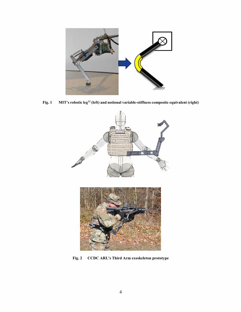
Fig. 1 MIT’s robotic leg (left) and notional variable-stiffness composite equivalent (right) ................................................................................... 4
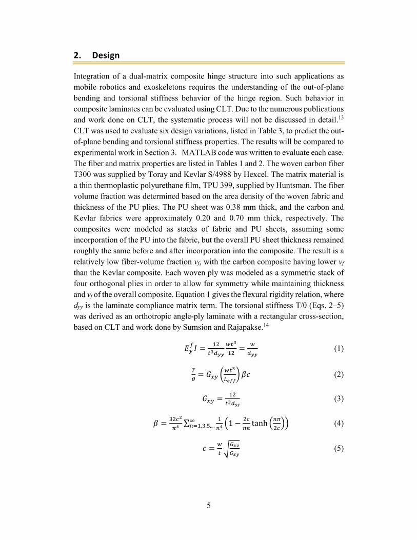
Fig. 2 CCDC ARL’s Third Arm exoskeleton prototype ................................. 4
Fig. 3 Model of composite hinge structure subjected to bending and torsion 7
Fig. 4 Effect of fiber orientation on out-of-plane flexural rigidity .................. 7
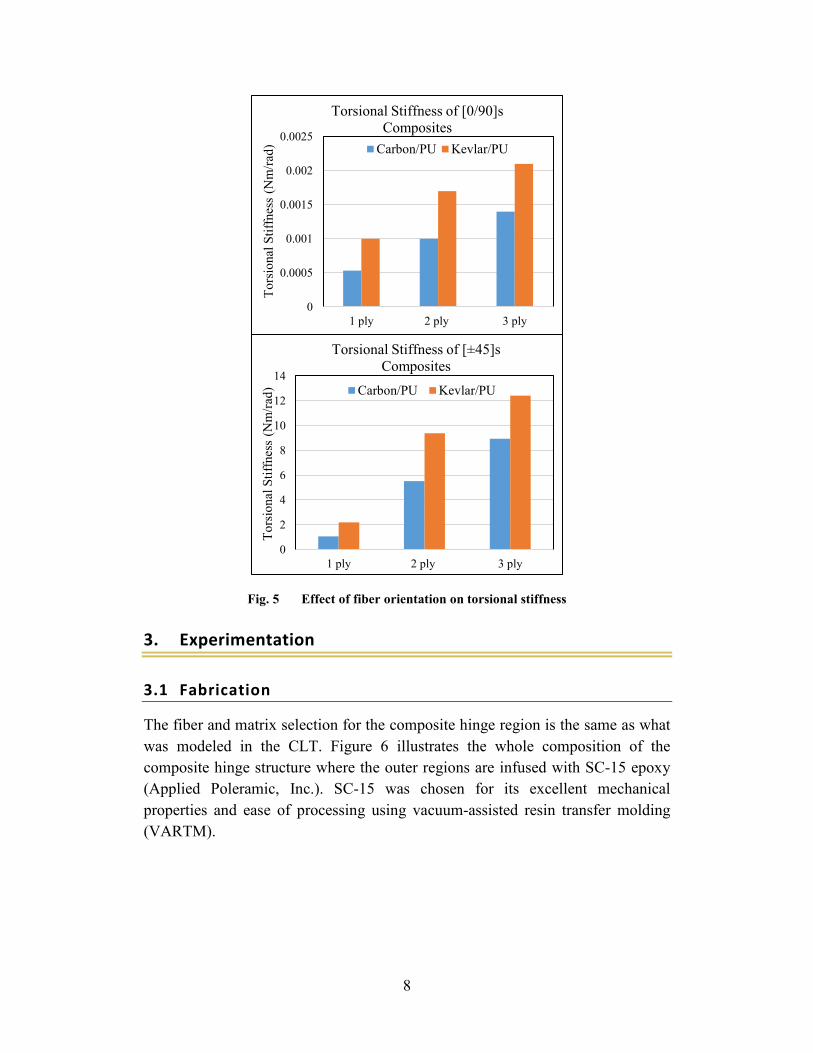
Fig. 5 Effect of fiber orientation on torsional stiffness ................................... 8
Fig. 6 Composition of composite fiber hinge structure ................................... 9
Fig. 7 Fabrication of composite hinge structure: A) Kevlar middle layer with PU strips and tape mask (blue), B) carbon fabric applied after PU cure, C) prepared for VARTM process, and D) cured composite with epoxy matrix .................................................................................................. 10
Fig. 8 Fabricated composite hinge samples in A) Design 1, B) Designs 2 and 3, C) Designs 4 and 5, and D) Design 6.............................................. 10
Fig. 9 Compression bend test, A) specimen at test start and B) specimen with 90° bend .............................................................................................. 11
Fig. 10 Free-body diagram of composite living hinge: A) rest position, B) compressed, and C) notional “knee” joint .......................................... 12
Fig. 11 Torsion test, A) DIC setup, B) 45° of twist (front), and C) 45° of twist (back) .................................................................................................. 13
Fig. 12 Geometric relations for deriving angle of twist in hinge region of the x–z plane ............................................................................................. 13
Fig. 13 Representative stress–strain relations from compression bend test .... 14
Fig. 13 Representative stress–strain relations from compression bend test (continued) .......................................................................................... 15
Fig. 14 Average flexural rigidity for each design ........................................... 16
Fig. 15 Microscopy images of localized damage in fibers: A) Design 2, B) Design 4, and C) Design 5 .................................................................. 18
Fig. 16 A) MIT’s one-legged robot with two segments and a compliant passive joint12 and B) free-body diagram ........................................................ 19
Fig. 17 Moment generated at notional hinge joint as a function of flexion angle .................................................................................................... 19
Fig. 18 Torsional load and stiffness during first cycle .................................... 20
Fig. 19 Low-cycle torsion test results ............................................................. 21
v
List of Tables
Table 1 Fabric selection and properties ............................................................. 6
Table 2 Mechanical properties of fiber and matrix selection............................. 6
Table 3 Design selections for composite hinge sections.................................... 9
Table 4 Flexural rigidity for Designs 1–5 ........................................................ 17
vi
Acknowledgments
The authors would like to thank Mr Michael Thompson and Mr Michael Neblett for their assistance in composite fabrication and Mr David Gray for his assistance in mechanical testing. The authors would like to thank Mr Jim Wolbert for his assistance in composite fabrication and for his friendship and mentorship over the years; he is dearly missed. This research was sponsored by the US Army Combat Capabilities Development Command (CCDC) Army Research Laboratory (ARL) and was accomplished under Cooperative Agreement no. W911NF-18-2-0199. The views and conclusions contained in this document are those of the authors and should not be interpreted as representing the official policies, either expressed or implied, of CCDC Army Research Laboratory or the US government. The US government is authorized to reproduce and distribute reprints for government purposes notwithstanding any copyright notation herein.
1
1. Introduction
1.1 Motivation
An overarching goal for exoskeleton and robot locomotion systems is to maximize the overall efficiency of the system by reducing mass, parts, and, as a result, manufacturing and assembly labor. The design and analysis to reach this desired goal becomes convoluted when trying to match the motion of complex human joints and the energy storage potential within muscle tissue during walking and running. Generally such systems will consist of a series of rigid members (“bones”) connected by single degree-of-freedom (DOF) metal hinges (“joints”) to produce the desired load-transfer pathway and appendage motion. These rigid members generally consist of lightweight metals such as aluminum or titanium or carbon-fiber composites that are as stiff and lightweight as possible to minimize the power and energy required to move them. To match the motion of the complexity of human joints, such as the shoulder or knee, often multiple 1-DOF metal hinges are used in series. These metal hinges can add significant bulk and mass to the exoskeleton or robot, and the interface between metal hinges and composite materials can be a point of failure. Misalignment of exoskeleton hinges’ discrete center of rotation with the human joint’s complex and mobile center of rotation can cause discomfort for the wearer and reduce effectiveness of the device. In robot appendages, where the need to store and release energy during locomotion is required, springs or motors are often mounted in parallel across 1-DOF hinges. The spring stiffness must be tailored to the robot’s mass and gait.1,2 While motors and control algorithms are often tuned to provide varied effective actuator stiffness, it may be more efficient for the stiffness of the appendage or spring element to be designed for the robot’s desired mass or gait.2
Composites with variable in-plane stiffness have the potential for tailorable hinge behavior in multiple rotation axes by specifying ply and fiber orientation. Composite hinges for exoskeletons could have broad curvatures, potentially alleviating functionality issues that arise from misalignment of human joints with metal hinges that have point centers of rotation. Such composite structures could provide a restorative or resistive force, eliminating the need for an external spring across a simple hinge, which could also reduce weight and improve efficiency of motion in mobile robotics.
2
1.2 Prior Work
The need for lightweight, foldable, deployable materials for outer-space structures spurred significant early work on high-deformation composites. Initial structures were rolls of fiber composites that unfurled to become long tubes, similar to the behavior of a steel tape measure.3 The entirety of these materials had one matrix material that did not vary along the length and were designed to deploy once. Dual-matrix composite materials for foldable structures have become a research area of interest in much more recent years.
Sergio Pellegrino’s group at the California Institute of Technology has performed extensive research on high-deformation composite materials for deployable space structures. Maqueda Jiménez’s thesis provides a review of this group’s work and also describes the manufacture and testing of a number of dual-matrix continuous fiber composites for foldable–deployable space structures.4 These materials consist of liquid silicone hand-applied and UV-cured to create the flexible regimes and epoxy film used in the stiff regimes. These composites are very thin, designed for low-load space applications, and designed to fold once for storage and deploy once (though multiple cycles may be possible). Maqueda Jiménez performed torsional tests on bulk rod samples as a means to determine longitudinal shear modulus to predict compression behavior. Most materials for deployable space structures are designed to resist bending and compression loads once deployed and are typically not designed or evaluated for torsional stiffness.
Platt’s thesis details the fabrication and testing of woven carbon-fiber composites with alternating polyurethane (PU) and epoxy regions.5 The intended application was a folding tray table for passenger aircraft, and thus the composites were thicker than those for deployable space structures. Samples were evaluated in constant-load 4-point bending, and anticlastic (multiaxis) curvature effects and interaction between matrices were examined. Wet layup was performed by hand, which led to issues with porosity. Torsion properties were not evaluated.
Tape springs for deployable space structures store elastic energy when bent for storage, and this energy is to deploy the structure.6,7 The form and function of these springs will be familiar to anyone who has used a slap bracelet. However, tape-spring structures for deployment in space are generally designed to fold once and unfold into a stiff structure.8 In related experiments, Lopez and Pellegrino examined folding of single-ply continuous carbon fibers in a silicone matrix.9 The authors used an unconventional compression-bend test to achieve high deformation in the material and through cyclic loading found evidence of damage though none was visible.
3
Talon Technology has a commercially available dual-matrix continuous fiber carbon–Kevlar composite hinge consisting of rigid outer wings and a flexible unit.10 The rigid wings have an epoxy matrix whereas the flexible unit has a urethane matrix. Due to their current design and fabrication process, the carbon–Kevlar hinge has a small radius of curvature, which limits the range of motion. This group performed high-cycle bend tests evaluating the stability of the flexible hinge unit as well as load strength. The results showed a slight reduction in the bending stiffness of the flexible hinge section. No evidence of damage was shown. Torsional properties were not reported.
1.3 Current Work and Applications
To the authors’ knowledge, dual-matrix composites with variable in-plane stiffness have not been applied to the field of exoskeletons and robotics. For these applications, it is generally desirable to create a composite hinge with tailorable out-of-plane bending stiffness and high torsional stiffness. In this work, the modeling, fabrication, and testing of fabric-based continuous fiber composites with regimes of varying in-plane stiffness will be investigated. Classical Laminate Theory (CLT) is used to predict the local effective out-of-plane bending and torsional rigidity. Samples are evaluated in high-deformation bending-compression tests and torsion tests, where low-cycle fatigue behavior is examined. In this report, composite design and experiments are geared toward composite living hinges for two example applications: a robotic leg joint (Fig. 1) and an exoskeleton prototype known as Third Arm (Fig. 2).11 The Massachusetts Institute of Technology’s (MIT’s) robotic leg provides an example of the general type of joint that a composite living hinge could replace: a metal pinned joint with a passive spring to provide restoring force.12 The spring stiffness must be tailored based on the mass and desired gait of the robot. Third Arm was designed by the US Army Combat Capabilities Development Command (CCDC) Army Research Laboratory (ARL) and comprises a series of rigid woven carbon-fiber laminate plates connected with steel fasteners to aluminum hinges. The aluminum hinges provide the stiffness necessary to support the load of weapons, shields, and tools weighing up to 30 lb while allowing smooth rotation and thus easy manipulation of the implement. However, the aluminum hinges and steel fasteners add weight and complexity to the overall device. The assembly of hinges and composite plates could be replaced by a single-piece composite with multiple, alternating hinge and rigid sections.
4
Fig. 1 MIT’s robotic leg12 (left) and notional variable-stiffness composite equivalent (right)
Fig. 2 CCDC ARL’s Third Arm exoskeleton prototype
5
2. Design
Integration of a dual-matrix composite hinge structure into such applications as mobile robotics and exoskeletons requires the understanding of the out-of-plane bending and torsional stiffness behavior of the hinge region. Such behavior in composite laminates can be evaluated using CLT. Due to the numerous publications and work done on CLT, the systematic process will not be discussed in detail.13 CLT was used to evaluate six design variations, listed in Table 3, to predict the out-of-plane bending and torsional stiffness properties. The results will be compared to experimental work in Section 3. MATLAB code was written to evaluate each case. The fiber and matrix properties are listed in Tables 1 and 2. The woven carbon fiber T300 was supplied by Toray and Kevlar S/4988 by Hexcel. The matrix material is a thin thermoplastic polyurethane film, TPU 399, supplied by Huntsman. The fiber volume fraction was determined based on the area density of the woven fabric and thickness of the PU plies. The PU sheet was 0.38 mm thick, and the carbon and Kevlar fabrics were approximately 0.20 and 0.70 mm thick, respectively. The composites were modeled as stacks of fabric and PU sheets, assuming some incorporation of the PU into the fabric, but the overall PU sheet thickness remained roughly the same before and after incorporation into the composite. The result is a relatively low fiber-volume fraction vf, with the carbon composite having lower vf than the Kevlar composite. Each woven ply was modeled as a symmetric stack of four orthogonal plies in order to allow for symmetry while maintaining thickness and vf of the overall composite. Equation 1 gives the flexural rigidity relation, where dyy is the laminate compliance matrix term. The torsional stiffness T/θ (Eqs. 2–5) was derived as an orthotropic angle-ply laminate with a rectangular cross-section, based on CLT and work done by Sumsion and Rajapakse.14
𝐸𝐸𝑦𝑦𝑓𝑓𝐼𝐼 = 12
𝑡𝑡3𝑑𝑑𝑦𝑦𝑦𝑦
𝑤𝑤𝑡𝑡3
12= 𝑤𝑤
𝑑𝑑𝑦𝑦𝑦𝑦 (1)
𝑇𝑇𝜃𝜃
= 𝐺𝐺𝑥𝑥𝑦𝑦 �𝑤𝑤𝑡𝑡3
𝐿𝐿𝑒𝑒𝑒𝑒𝑒𝑒� 𝛽𝛽𝛽𝛽 (2)
𝐺𝐺𝑥𝑥𝑦𝑦 = 12𝑡𝑡3𝑑𝑑𝑠𝑠𝑠𝑠
(3)
𝛽𝛽 = 32𝑐𝑐2
𝜋𝜋4∑ 1
𝑛𝑛4�1 − 2𝑐𝑐
𝑛𝑛𝜋𝜋tanh �𝑛𝑛𝜋𝜋
2𝑐𝑐��∞
𝑛𝑛=1,3,5,... (4)
𝛽𝛽 = 𝑤𝑤𝑡𝑡 �
𝐺𝐺𝑥𝑥𝑥𝑥𝐺𝐺𝑥𝑥𝑦𝑦
(5)

6
Table 1 Fabric selection and properties
Fabric style Carbon T300 Kevlar S/4988
Weight, g/m2 197 508
Weave construction Plain 8 × 8 Basket
Count, yarns/cm 4.72 × 4.72 15.7 × 15.7
Yarn type 3K Carbon K49 1420 Denier
Table 2 Mechanical properties of fiber and matrix selection
Fiber properties Carbon T300 Kevlar S/4988 Matrix properties TPU 399
𝐸𝐸1𝑓𝑓 (GPa) 230 131 … …
𝐸𝐸2𝑓𝑓 (GPa) 15 7 𝐸𝐸𝑚𝑚 (MPa) 2.0
𝐺𝐺12𝑓𝑓 (GPa) 27 21 𝐺𝐺𝑚𝑚 (MPa) 0.68
𝑣𝑣12 0.20 0.33 𝑣𝑣𝑚𝑚 0.47
The flexural rigidity and torsional stiffness are dependent on the geometry of the rectangular specimen as represented in Fig. 3, where w, t, and 𝐿𝐿𝑒𝑒𝑓𝑓𝑓𝑓 represent the width, thickness, and effective length of the flexible hinge region, respectively. The in-plane shear modulus Gxy is derived based on CLT (Eq. 3). In this model, obtaining an accurate approximation of out-of-plane (through thickness) shear modulus Gxz or ratio of Gxz/Gxy is key. Gxz is difficult to predict without conducting experimental torsion tests about the fiber direction and transverse to the fiber direction, as described in the work of Tsai and Daniel.15 However, Sumsion and Rajapakse showed for an angle-ply carbon–epoxy laminate in torsion, the out-of-plane shear modulus was approximately 92% lower than the in-plane shear modulus.14 For the purpose of this study, an approximation of Gxz/Gxy of 0.005:1 was used, taking into consideration the low-modulus PU matrix of these thin composites. Prior to fabrication and experimentation, the out-of-plane bending and torsional stiffnesses were evaluated for several laminate design cases using Eqs. 1–5. The results shown in Figs. 4 and 5 demonstrate how the fiber selection and orientation and the number of plies influence the previously mentioned properties of each laminate. The results in Fig. 4 demonstrate that flexural rigidity is a fiber-dominated property for [0/90]s composites with bending modulus 𝐸𝐸𝑦𝑦
𝑓𝑓
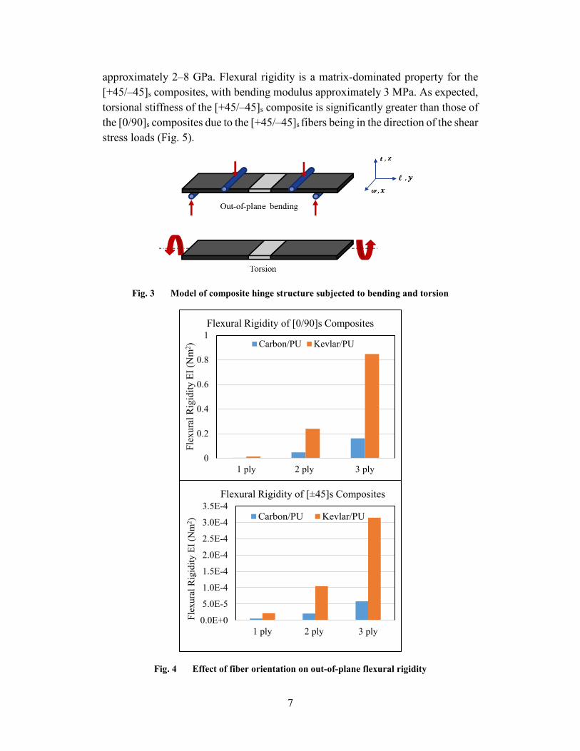
7
approximately 2–8 GPa. Flexural rigidity is a matrix-dominated property for the [+45/–45]s composites, with bending modulus approximately 3 MPa. As expected, torsional stiffness of the [+45/–45]s composite is significantly greater than those of the [0/90]s composites due to the [+45/–45]s fibers being in the direction of the shear stress loads (Fig. 5).
Fig. 3 Model of composite hinge structure subjected to bending and torsion
Fig. 4 Effect of fiber orientation on out-of-plane flexural rigidity
0
0.2
0.4
0.6
0.8
1
1 ply 2 ply 3 ply
Flex
ural
Rig
idity
EI (
Nm
2 )
Flexural Rigidity of [0/90]s Composites
Carbon/PU Kevlar/PU
0.0E+0
5.0E-5
1.0E-4
1.5E-4
2.0E-4
2.5E-4
3.0E-4
3.5E-4
1 ply 2 ply 3 ply
Flex
ural
Rig
idity
EI (
Nm
2 )
Flexural Rigidity of [±45]s Composites
Carbon/PU Kevlar/PU
8
Fig. 5 Effect of fiber orientation on torsional stiffness
3. Experimentation
3.1 Fabrication
The fiber and matrix selection for the composite hinge region is the same as what was modeled in the CLT. Figure 6 illustrates the whole composition of the composite hinge structure where the outer regions are infused with SC-15 epoxy (Applied Poleramic, Inc.). SC-15 was chosen for its excellent mechanical properties and ease of processing using vacuum-assisted resin transfer molding (VARTM).
0
0.0005
0.001
0.0015
0.002
0.0025
1 ply 2 ply 3 ply
Tors
iona
l Stif
fnes
s (N
m/ra
d)
Torsional Stiffness of [0/90]s Composites
Carbon/PU Kevlar/PU
0
2
4
6
8
10
12
14
1 ply 2 ply 3 ply
Tors
iona
l Stif
fnes
s (N
m/ra
d)
Torsional Stiffness of [±45]s Composites
Carbon/PU Kevlar/PU
9
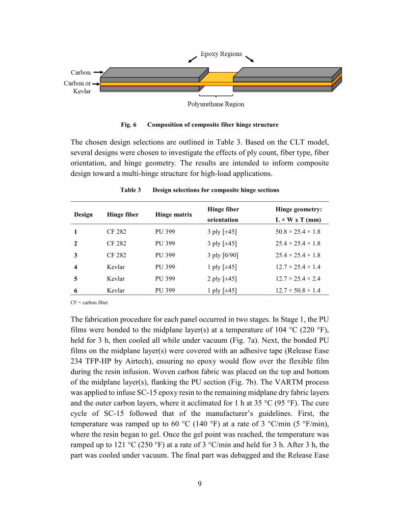
Fig. 6 Composition of composite fiber hinge structure
The chosen design selections are outlined in Table 3. Based on the CLT model, several designs were chosen to investigate the effects of ply count, fiber type, fiber orientation, and hinge geometry. The results are intended to inform composite design toward a multi-hinge structure for high-load applications.
Table 3 Design selections for composite hinge sections
Design Hinge fiber Hinge matrix Hinge fiber orientation
Hinge geometry: L × W x T (mm)
1 CF 282 PU 399 3 ply [±45] 50.8 × 25.4 × 1.8
2 CF 282 PU 399 3 ply [±45] 25.4 × 25.4 × 1.8
3 CF 282 PU 399 3 ply [0/90] 25.4 × 25.4 × 1.8
4 Kevlar PU 399 1 ply [±45] 12.7 × 25.4 × 1.4
5 Kevlar PU 399 2 ply [±45] 12.7 × 25.4 × 2.4
6 Kevlar PU 399 1 ply [±45] 12.7 × 50.8 × 1.4
CF = carbon fiber
The fabrication procedure for each panel occurred in two stages. In Stage 1, the PU films were bonded to the midplane layer(s) at a temperature of 104 °C (220 °F), held for 3 h, then cooled all while under vacuum (Fig. 7a). Next, the bonded PU films on the midplane layer(s) were covered with an adhesive tape (Release Ease 234 TFP-HP by Airtech), ensuring no epoxy would flow over the flexible film during the resin infusion. Woven carbon fabric was placed on the top and bottom of the midplane layer(s), flanking the PU section (Fig. 7b). The VARTM process was applied to infuse SC-15 epoxy resin to the remaining midplane dry fabric layers and the outer carbon layers, where it acclimated for 1 h at 35 °C (95 °F). The cure cycle of SC-15 followed that of the manufacturer’s guidelines. First, the temperature was ramped up to 60 °C (140 °F) at a rate of 3 °C/min (5 °F/min), where the resin began to gel. Once the gel point was reached, the temperature was ramped up to 121 °C (250 °F) at a rate of 3 °C/min and held for 3 h. After 3 h, the part was cooled under vacuum. The final part was debagged and the Release Ease
10
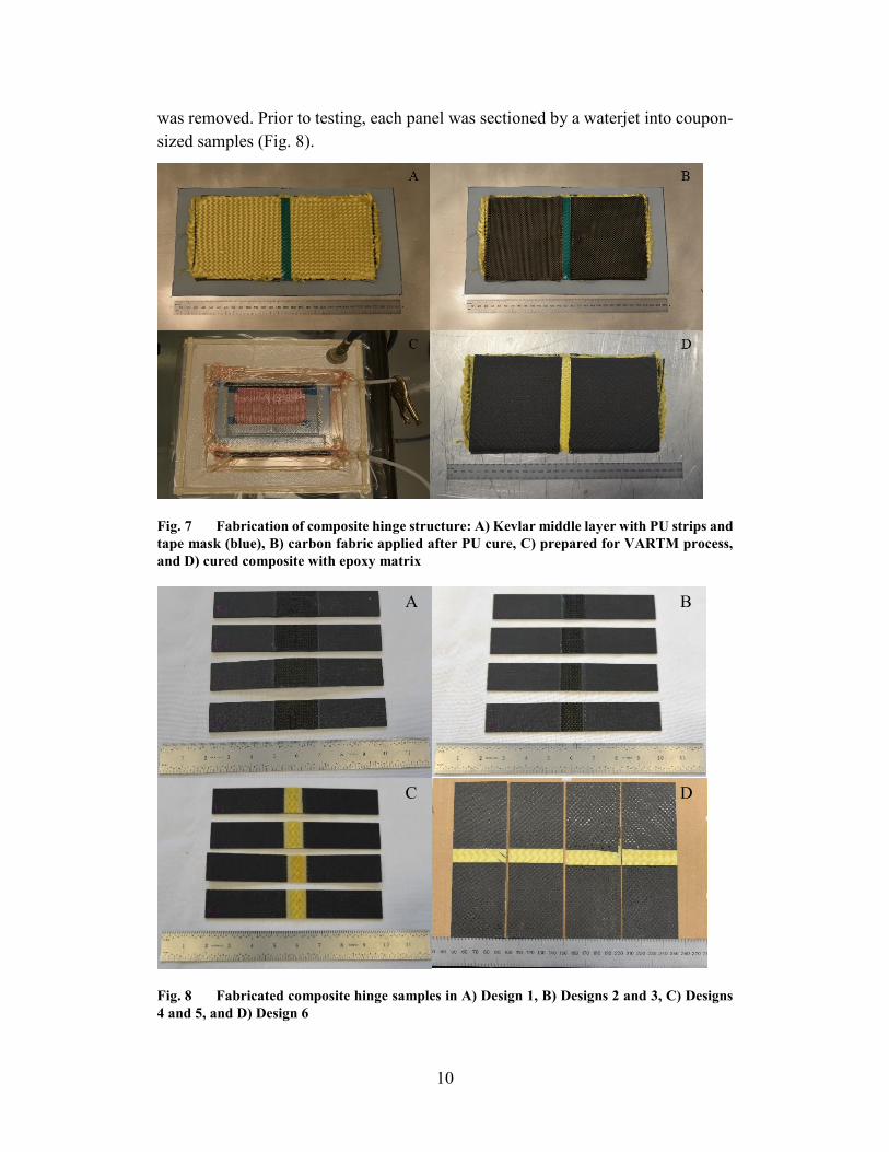
was removed. Prior to testing, each panel was sectioned by a waterjet into coupon-sized samples (Fig. 8).
Fig. 7 Fabrication of composite hinge structure: A) Kevlar middle layer with PU strips and tape mask (blue), B) carbon fabric applied after PU cure, C) prepared for VARTM process, and D) cured composite with epoxy matrix
Fig. 8 Fabricated composite hinge samples in A) Design 1, B) Designs 2 and 3, C) Designs 4 and 5, and D) Design 6
A B
C D
11
3.2 Testing
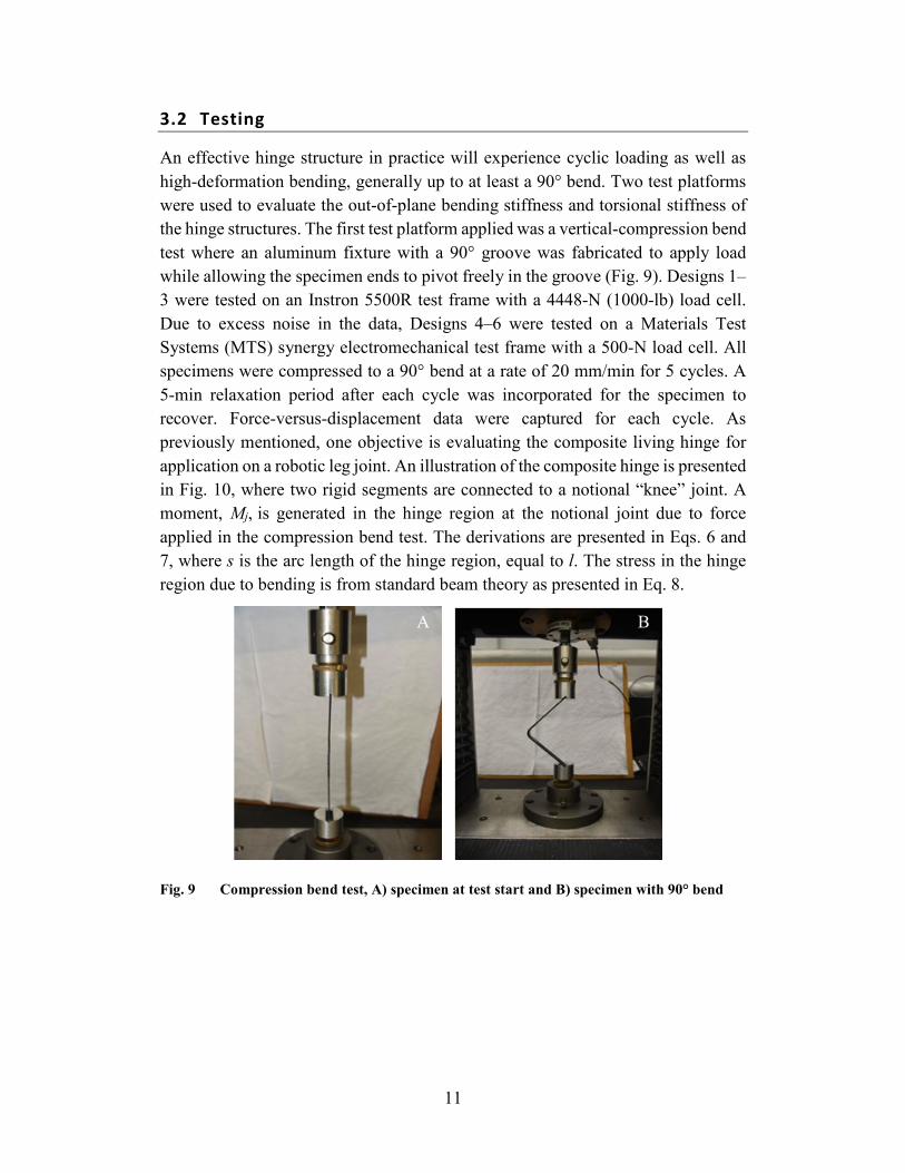
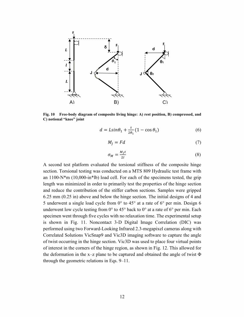
An effective hinge structure in practice will experience cyclic loading as well as high-deformation bending, generally up to at least a 90° bend. Two test platforms were used to evaluate the out-of-plane bending stiffness and torsional stiffness of the hinge structures. The first test platform applied was a vertical-compression bend test where an aluminum fixture with a 90° groove was fabricated to apply load while allowing the specimen ends to pivot freely in the groove (Fig. 9). Designs 1–3 were tested on an Instron 5500R test frame with a 4448-N (1000-lb) load cell. Due to excess noise in the data, Designs 4–6 were tested on a Materials Test Systems (MTS) synergy electromechanical test frame with a 500-N load cell. All specimens were compressed to a 90° bend at a rate of 20 mm/min for 5 cycles. A 5-min relaxation period after each cycle was incorporated for the specimen to recover. Force-versus-displacement data were captured for each cycle. As previously mentioned, one objective is evaluating the composite living hinge for application on a robotic leg joint. An illustration of the composite hinge is presented in Fig. 10, where two rigid segments are connected to a notional “knee” joint. A moment, Mj, is generated in the hinge region at the notional joint due to force applied in the compression bend test. The derivations are presented in Eqs. 6 and 7, where s is the arc length of the hinge region, equal to l. The stress in the hinge region due to bending is from standard beam theory as presented in Eq. 8.
Fig. 9 Compression bend test, A) specimen at test start and B) specimen with 90° bend
A B
12
Fig. 10 Free-body diagram of composite living hinge: A) rest position, B) compressed, and C) notional “knee” joint
𝑑𝑑 = 𝐿𝐿𝐿𝐿𝐿𝐿𝐿𝐿𝜃𝜃1 + 𝑠𝑠2𝜃𝜃1
(1 − cos 𝜃𝜃1) (6)
𝑀𝑀𝐽𝐽 = 𝐹𝐹𝑑𝑑 (7)
𝜎𝜎𝑀𝑀 = 𝑀𝑀𝐽𝐽𝑡𝑡2𝐼𝐼
(8)
A second test platform evaluated the torsional stiffness of the composite hinge section. Torsional testing was conducted on a MTS 809 Hydraulic test frame with an 1100-N*m (10,000-in*lb) load cell. For each of the specimens tested, the grip length was minimized in order to primarily test the properties of the hinge section and reduce the contribution of the stiffer carbon sections. Samples were gripped 6.25 mm (0.25 in) above and below the hinge section. The initial designs of 4 and 5 underwent a single load cycle from 0° to 45° at a rate of 6° per min. Design 6 underwent low cycle testing from 0° to 45° back to 0° at a rate of 6° per min. Each specimen went through five cycles with no relaxation time. The experimental setup is shown in Fig. 11. Noncontact 3-D Digital Image Correlation (DIC) was performed using two Forward-Looking Infrared 2.3-megapixel cameras along with Correlated Solutions VicSnap9 and Vic3D imaging software to capture the angle of twist occurring in the hinge section. Vic3D was used to place four virtual points of interest in the corners of the hinge region, as shown in Fig. 12. This allowed for the deformation in the x–z plane to be captured and obtained the angle of twist Φ through the geometric relations in Eqs. 9–11.
𝒍𝒍
𝑳𝑳
𝑳𝑳
F
F
𝜽𝜽𝟏𝟏
d
δ
θ1
F
J θ2 J
d
A) B) C)

13
Fig. 11 Torsion test, A) DIC setup, B) 45° of twist (front), and C) 45° of twist (back)
𝜃𝜃12 = 𝑡𝑡𝑡𝑡𝐿𝐿−1( 𝑤𝑤2−𝑤𝑤1𝑥𝑥2−𝑥𝑥1+𝑢𝑢2−𝑢𝑢1
) (9)
𝜃𝜃34 = 𝑡𝑡𝑡𝑡𝐿𝐿−1( 𝑤𝑤4−𝑤𝑤3𝑥𝑥4−𝑥𝑥3+𝑢𝑢4−𝑢𝑢3
) (10)
Φ = 𝜃𝜃34 − 𝜃𝜃12 (11)
Fig. 12 Geometric relations for deriving angle of twist in hinge region of the x–z plane
4. Results
4.1 Compression Bend Test
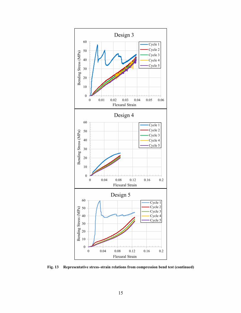
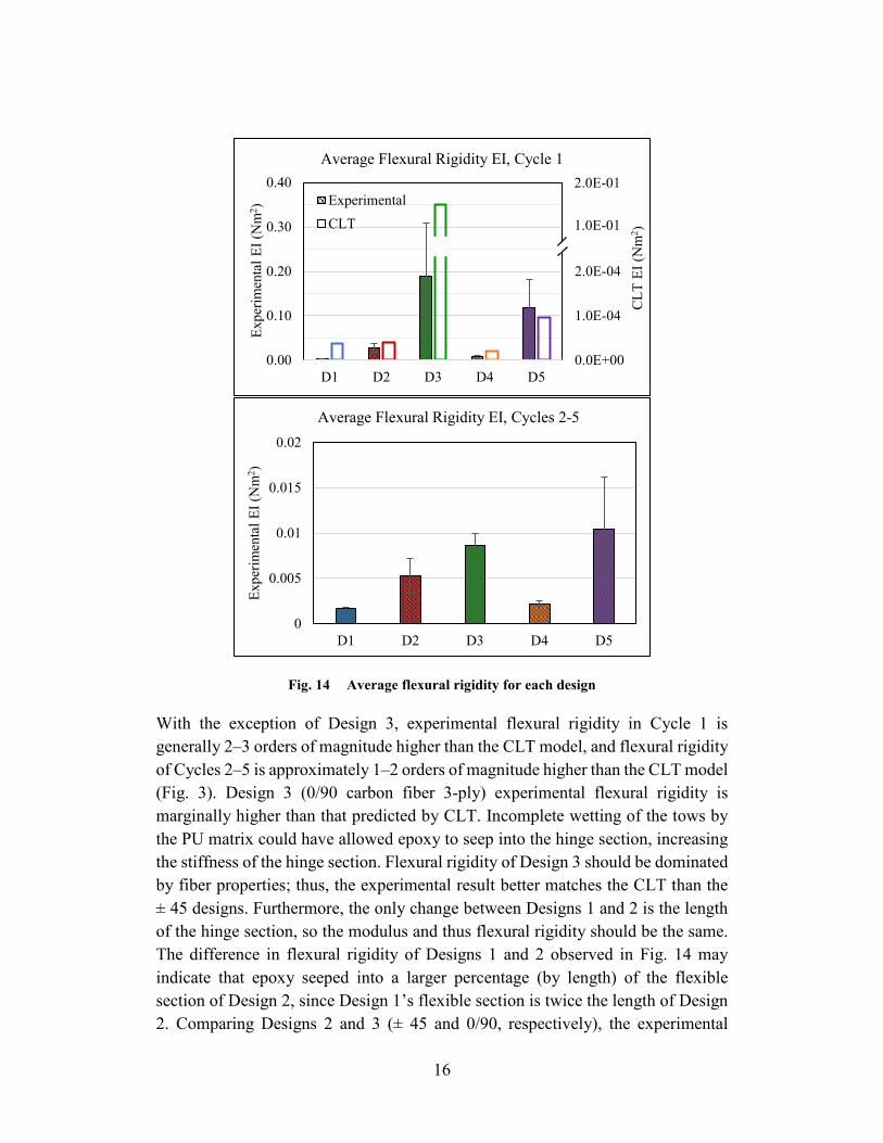
The representative compression-bend-test stress–strain curves for Designs 1–5 are presented in Fig. 13. Note the scaling of the x-axis for Designs 4 and 5 vary from Designs 1–3. Each of the design cases exhibits a nonlinear behavior that is most significant in Cycle 1. During Cycle 1 there are noticeable discontinuities in Designs 3 and 5, which likely occur due to delamination, fiber damage, and/or PU–epoxy matrix interfacial damage. Cycles 2–5 show good repeatability of mechanical behavior. Figure 14 shows the flexural rigidity of Cycle 1 and Cycles 2–5, with the modulus taken as the initial linear slope of the stress–strain curve.
A B C
Clamped End
1 2
3 4
Clamped End
𝑻𝑻𝒚𝒚
𝒙𝒙 𝒛𝒛
𝒚𝒚 DIC Region

14
Due to the minimal preloading applied, slight variations in offsets were used for each design case to evaluate the initial modulus. For Designs 1–4, the modulus was evaluated in the range of 0.2% to 0.4% strain for Cycle 1 and 0.5% to 1.0% strain for Cycles 2–5. The initial modulus for Design 5 was evaluated in the range of 1.4% to 1.8% strain for Cycle 1 and 1.0% to 1.4% strain for Cycles 2–5.
0
10
20
30
40
50
60
0 0.01 0.02 0.03 0.04 0.05 0.06
Ben
ding
Stre
ss (M
Pa)
Flexural Strain
Design 1Cycle 1Cycle 2Cycle 3Cycle 4Cycle 5
0
10
20
30
40
50
60
0 0.01 0.02 0.03 0.04 0.05 0.06
Ben
ding
Stre
ss (M
Pa)
Flexural Strain
Design 2Cycle 1Cycle 2Cycle 3Cycle 4Cycle 5
Fig. 13 Representative stress–strain relations from compression bend test
15
Fig. 13 Representative stress–strain relations from compression bend test (continued)
0
10
20
30
40
50
60
0 0.01 0.02 0.03 0.04 0.05 0.06
Ben
ding
Stre
ss (M
Pa)
Flexural Strain
Design 3Cycle 1Cycle 2Cycle 3Cycle 4Cycle 5
0
10
20
30
40
50
60
0 0.04 0.08 0.12 0.16 0.2
Ben
ding
Stre
ss (M
Pa)
Flexural Strain
Design 4
Cycle 1Cycle 2Cycle 3Cycle 4Cycle 5
0
10
20
30
40
50
60
0 0.04 0.08 0.12 0.16 0.2
Ben
ding
Stre
ss (M
Pa)
Flexural Strain
Design 5Cycle 1Cycle 2Cycle 3Cycle 4Cycle 5
16
Fig. 14 Average flexural rigidity for each design
With the exception of Design 3, experimental flexural rigidity in Cycle 1 is generally 2–3 orders of magnitude higher than the CLT model, and flexural rigidity of Cycles 2–5 is approximately 1–2 orders of magnitude higher than the CLT model (Fig. 3). Design 3 (0/90 carbon fiber 3-ply) experimental flexural rigidity is marginally higher than that predicted by CLT. Incomplete wetting of the tows by the PU matrix could have allowed epoxy to seep into the hinge section, increasing the stiffness of the hinge section. Flexural rigidity of Design 3 should be dominated by fiber properties; thus, the experimental result better matches the CLT than the ± 45 designs. Furthermore, the only change between Designs 1 and 2 is the length of the hinge section, so the modulus and thus flexural rigidity should be the same. The difference in flexural rigidity of Designs 1 and 2 observed in Fig. 14 may indicate that epoxy seeped into a larger percentage (by length) of the flexible section of Design 2, since Design 1’s flexible section is twice the length of Design 2. Comparing Designs 2 and 3 (± 45 and 0/90, respectively), the experimental
0
0.005
0.01
0.015
0.02
D1 D2 D3 D4 D5
Expe
rimen
tal E
I (N
m2 )
Average Flexural Rigidity EI, Cycles 2-5
0.0E+00
1.0E-04
2.0E-04
3.0E-04
4.0E-04
0.00
0.10
0.20
0.30
0.40
D1 D2 D3 D4 D5
CLT
EI (
Nm
2 )
Expe
rimen
tal E
I (N
m2 )
Average Flexural Rigidity EI, Cycle 1
ExperimentalCLT 1.0E-01
2.0E-01
17
flexural rigidity follows the expected trend from CLT, with a significant increase from Design 2 to 3. Designs 4 and 5 also exhibit the expected trend of significant increase in flexural rigidity when ply count is doubled.
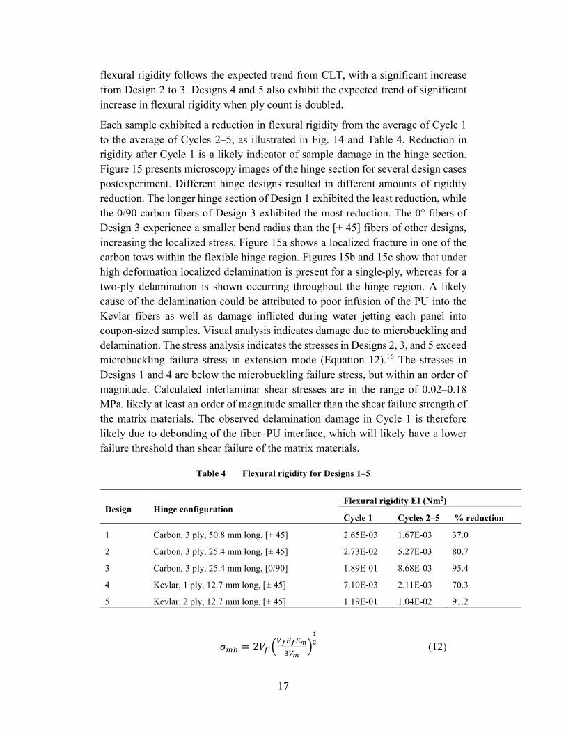
Each sample exhibited a reduction in flexural rigidity from the average of Cycle 1 to the average of Cycles 2–5, as illustrated in Fig. 14 and Table 4. Reduction in rigidity after Cycle 1 is a likely indicator of sample damage in the hinge section. Figure 15 presents microscopy images of the hinge section for several design cases postexperiment. Different hinge designs resulted in different amounts of rigidity reduction. The longer hinge section of Design 1 exhibited the least reduction, while the 0/90 carbon fibers of Design 3 exhibited the most reduction. The 0° fibers of Design 3 experience a smaller bend radius than the [± 45] fibers of other designs, increasing the localized stress. Figure 15a shows a localized fracture in one of the carbon tows within the flexible hinge region. Figures 15b and 15c show that under high deformation localized delamination is present for a single-ply, whereas for a two-ply delamination is shown occurring throughout the hinge region. A likely cause of the delamination could be attributed to poor infusion of the PU into the Kevlar fibers as well as damage inflicted during water jetting each panel into coupon-sized samples. Visual analysis indicates damage due to microbuckling and delamination. The stress analysis indicates the stresses in Designs 2, 3, and 5 exceed microbuckling failure stress in extension mode (Equation 12).16 The stresses in Designs 1 and 4 are below the microbuckling failure stress, but within an order of magnitude. Calculated interlaminar shear stresses are in the range of 0.02–0.18 MPa, likely at least an order of magnitude smaller than the shear failure strength of the matrix materials. The observed delamination damage in Cycle 1 is therefore likely due to debonding of the fiber–PU interface, which will likely have a lower failure threshold than shear failure of the matrix materials.
Table 4 Flexural rigidity for Designs 1–5
Design Hinge configuration Flexural rigidity EI (Nm2)
Cycle 1 Cycles 2–5 % reduction
1 Carbon, 3 ply, 50.8 mm long, [± 45] 2.65E-03 1.67E-03 37.0
2 Carbon, 3 ply, 25.4 mm long, [± 45] 2.73E-02 5.27E-03 80.7
3 Carbon, 3 ply, 25.4 mm long, [0/90] 1.89E-01 8.68E-03 95.4
4 Kevlar, 1 ply, 12.7 mm long, [± 45] 7.10E-03 2.11E-03 70.3
5 Kevlar, 2 ply, 12.7 mm long, [± 45] 1.19E-01 1.04E-02 91.2
𝜎𝜎𝑚𝑚𝑚𝑚 = 2𝑉𝑉𝑓𝑓 �𝑉𝑉𝑒𝑒𝐸𝐸𝑒𝑒𝐸𝐸𝑚𝑚3𝑉𝑉𝑚𝑚
�12 (12)

18
Fig. 15 Microscopy images of localized damage in fibers: A) Design 2, B) Design 4, and C) Design 5
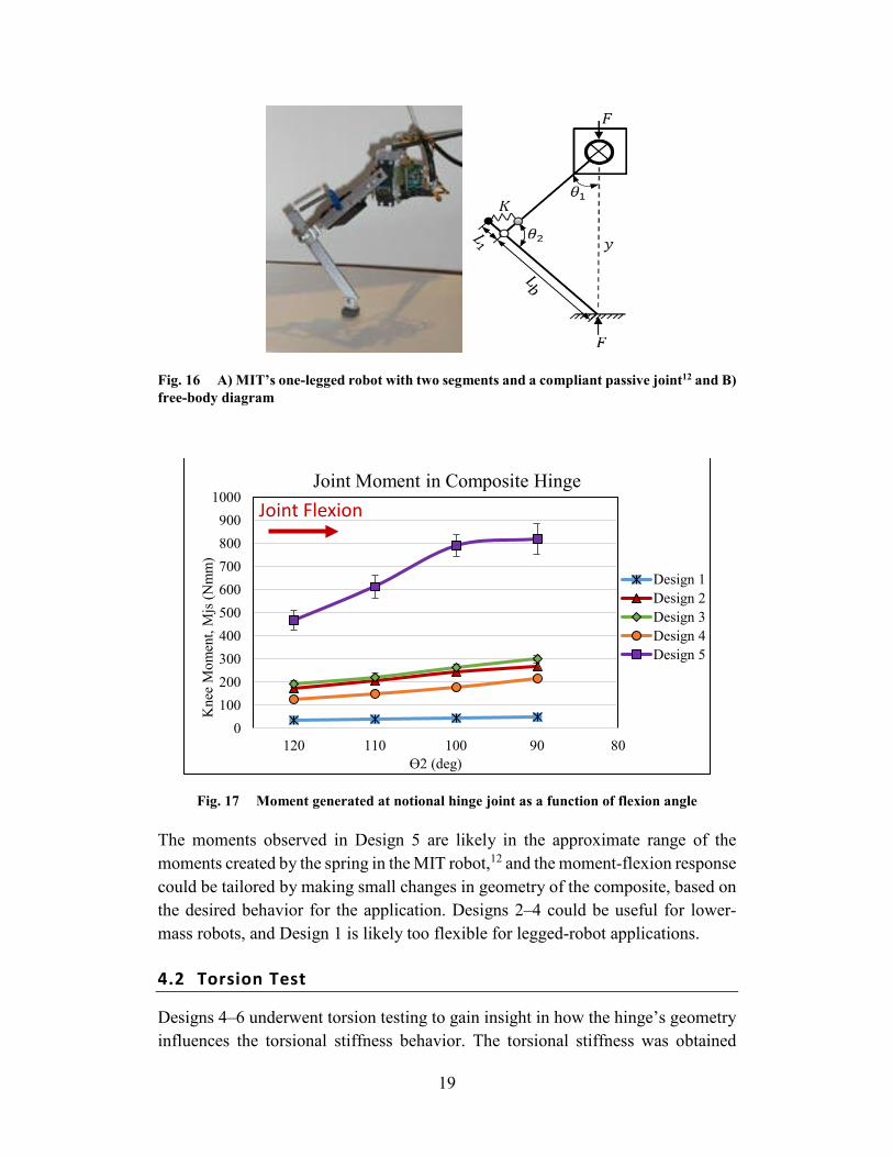
As mentioned in the introduction section, one potential application of these composite living hinges is a robotic leg with a compliant passive joint. The example robotic structure was designed at MIT’s Computer Science and Artificial Intelligence Laboratory.12 The design is shown in Fig. 16. It consists of a rigid, lightweight metal thigh and shank segment connected to a pivot point “knee joint.” A spring is attached between the thigh and shank segments to store and release energy during locomotion. The equivalent composite living hinge is illustrated in Fig. 10. The composite hinge is represented as two rigid segments, thigh and shank, connected to a notional knee joint. A moment is generated at the hinge, or notional knee joint, due to force applied in the compression bend test as discussed in Section 2.3. The moments were evaluated for Designs 1–5 for selected knee angles in the operating range of the leg by Fumiya and Tedrake12 and are presented in Fig. 17. Moment at the center of the composite hinge increases with decreasing angle θ2 (increased flexion), as does the knee moment created by the spring in the MIT robot.12
A)
B)
C)
20x Mag 20x Mag 50x Mag
30x Mag 100x Mag 20x Mag
20x Mag 30x Mag 20x Mag
19
Fig. 16 A) MIT’s one-legged robot with two segments and a compliant passive joint12 and B) free-body diagram
Fig. 17 Moment generated at notional hinge joint as a function of flexion angle
The moments observed in Design 5 are likely in the approximate range of the moments created by the spring in the MIT robot,12 and the moment-flexion response could be tailored by making small changes in geometry of the composite, based on the desired behavior for the application. Designs 2–4 could be useful for lower-mass robots, and Design 1 is likely too flexible for legged-robot applications.
4.2 Torsion Test
Designs 4–6 underwent torsion testing to gain insight in how the hinge’s geometry influences the torsional stiffness behavior. The torsional stiffness was obtained
0100200300400500600700800900
1000
8090100110120
Kne
e M
omen
t, M
js (N
mm
)
ϴ2 (deg)
Joint Moment in Composite Hinge
Design 1Design 2Design 3Design 4Design 5
Joint Flexion
20
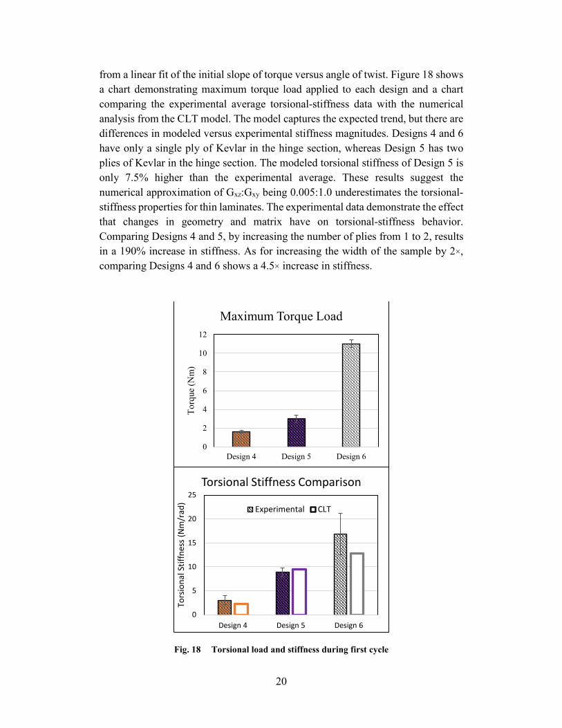
from a linear fit of the initial slope of torque versus angle of twist. Figure 18 shows a chart demonstrating maximum torque load applied to each design and a chart comparing the experimental average torsional-stiffness data with the numerical analysis from the CLT model. The model captures the expected trend, but there are differences in modeled versus experimental stiffness magnitudes. Designs 4 and 6 have only a single ply of Kevlar in the hinge section, whereas Design 5 has two plies of Kevlar in the hinge section. The modeled torsional stiffness of Design 5 is only 7.5% higher than the experimental average. These results suggest the numerical approximation of Gxz:Gxy being 0.005:1.0 underestimates the torsional-stiffness properties for thin laminates. The experimental data demonstrate the effect that changes in geometry and matrix have on torsional-stiffness behavior. Comparing Designs 4 and 5, by increasing the number of plies from 1 to 2, results in a 190% increase in stiffness. As for increasing the width of the sample by 2×, comparing Designs 4 and 6 shows a 4.5× increase in stiffness.
Fig. 18 Torsional load and stiffness during first cycle
0
2
4
6
8
10
12
Design 4 Design 5 Design 6
Torq
ue (N
m)
Maximum Torque Load
0
5
10
15
20
25
Design 4 Design 5 Design 6
Tors
iona
l Stif
fnes
s (N
m/r
ad)
Torsional Stiffness Comparison
Experimental CLT
21
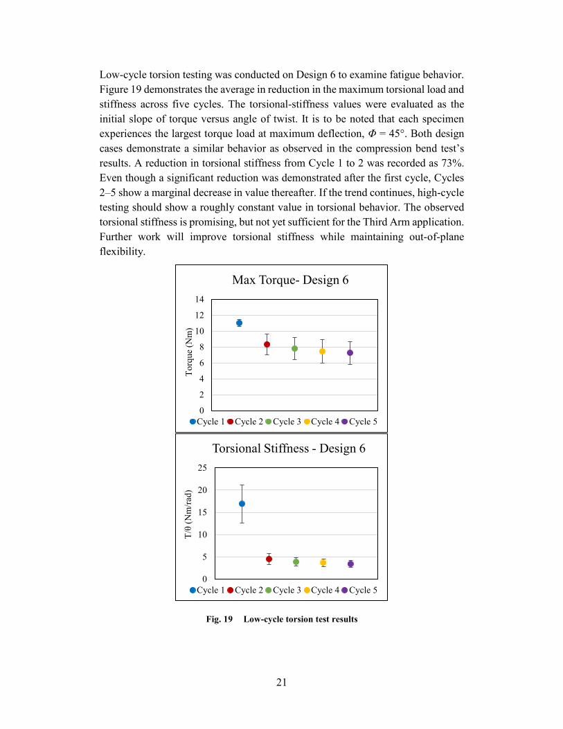
Low-cycle torsion testing was conducted on Design 6 to examine fatigue behavior. Figure 19 demonstrates the average in reduction in the maximum torsional load and stiffness across five cycles. The torsional-stiffness values were evaluated as the initial slope of torque versus angle of twist. It is to be noted that each specimen experiences the largest torque load at maximum deflection, Φ = 45°. Both design cases demonstrate a similar behavior as observed in the compression bend test’s results. A reduction in torsional stiffness from Cycle 1 to 2 was recorded as 73%. Even though a significant reduction was demonstrated after the first cycle, Cycles 2–5 show a marginal decrease in value thereafter. If the trend continues, high-cycle testing should show a roughly constant value in torsional behavior. The observed torsional stiffness is promising, but not yet sufficient for the Third Arm application. Further work will improve torsional stiffness while maintaining out-of-plane flexibility.
Fig. 19 Low-cycle torsion test results
0
2
4
6
8
10
12
14
Torq
ue (N
m)
Max Torque- Design 6
Cycle 1 Cycle 2 Cycle 3 Cycle 4 Cycle 5
0
5
10
15
20
25
T/θ
(Nm
/rad)
Torsional Stiffness - Design 6
Cycle 1 Cycle 2 Cycle 3 Cycle 4 Cycle 5
22
5. Conclusion
This report demonstrated a novel method for manufacturing living hinges consisting of continuous fiber woven composites of carbon fiber, Kevlar, epoxy, and PU. CLT captured the general trend expected when changing ply count, fiber type, and fiber orientation, but the experimental flexural rigidity was significantly different than the model predictions. These differences may have been due to incomplete wetting of the PU in the flexible regions and epoxy subsequently seeping into some of the tows and subsequently increasing the experimental stiffness. Low-cycle bend testing showed that flexural rigidity was significantly reduced after the first cycle, but remained relatively unchanged upon further cycles. With refinement in manufacturing methods, experimental flexural rigidity could better match model predictions, enabling composite hinges with more precisely tailored effective spring stiffness. The tailorability of the moment generated at the notional hinge “knee” joint of the composite living hinge opens up a wide range of potential robotic applications. The high-deformation tests in this report demonstrated composite joint moment behavior was likely in the range required for a robotic leg application. The modeled torsional stiffness of these composite hinges agreed well with experimental results for initial loading. The ability to predict, design, and characterize torsional and flexural stiffness of these composites could allow them to replace typical hinged appendage assemblies in small robots, thus reducing weight and complexity of the robot.
Future work: Improvements to the manufacturing method could prevent epoxy from seeping into the tows of the flexible hinge section. A liquid PU could be infused into the entire area of the flexible fabric layer or layers, then the flexible section could be masked while epoxy resin is infused into the rigid fabrics flanking the flexible region. This manufacturing method may also allow for improved torsional stiffness through reduction in the flexible region’s length. Torsional stiffness could also be improved by increasing the overall sample width and ply count, although the latter will increase out-of-plane bending stiffness. Additional high-cycle, high-deformation testing could better determine the fatigue behavior of composite hinges for robotic applications. Future work will examine these changes and the possibility of enabling a composite hinge structure sufficient for Third Arm.
23
6. References
1. Jun JY, Clark JE. Dynamic stability of variable stiffness running. Proceedings of the 2009 IEEE International Conference on Robotics and Automation; 2009 May 12–17; Kobe, Japan: IEEE; p. 1756–1761.
2. Hurst JW, Rizzi AA. Series compliance for an efficient running gait. IEEE Robo Auto Mag. 2008;15(3):42–51.
3. Groskopfs E. Storable tubular extensible member device. United States patent US 3,434,674. 1969 Mar 25.
4. Maqueda Jiménez I. High strain composites and dual-matrix composite structures [dissertation]. [Pasadena (CA)]: California Institute of Technology; 2014.
5. Platt DL. Tailoring the bending stiffness of elastomeric dual-matrix composites [master’s thesis]. [Toronto, Canada]: University of Toronto; 2016.
6. Yee JC, Pellegrino S. Composite tube hinges. J Aero Eng. 2005;18(4):224–231.
7. Mallikarachchi HMYC, Pellegrino S. Quasi-static folding and deployment of ultrathin composite tape-spring hinges. J Space Rock. 2011;48:187–198.
8. Sakovsky M, Pellegrino S. Closed cross-section dual-matrix composite hinge for deployable structures. J Comp Struc. 2019;208:784–795.
9. López JF, Pellegrino S. Folding of fiber composites with a hyperelastic matrix. Int J Sol Struc. 2013;49(3–4):395–407.
10. Carbon-Kevlar hinge. Sydney, Australia: Talon Technology; c2017 [accessed 2020 May]. https://www.carbonhinge.com.
11. Lacdan J. Army researchers advance ‘Third Arm’ project to next testing phase. Army News Service; 2018 Mar 1 [accessed 2020 May]. https://www.army.mil/article/201229/army_researchers_advance_third_arm_project_to_next_testing_phase
12. Fumiya I, Tedrake R. Motor control optimization of compliant one-legged locomotion in rough terrain. 2007 IEEE/RSJ International Conference on Intelligent Robots and Systems; 2007 Oct 29–Nov 2, San Diego, CA. p. 2230–2235.
13. Daniel IM, Ishai O. Engineering mechanics of composite materials. 2nd ed. New York (NY): Oxford University Press; 2006.

24
14. Sumsion HT, Rajapakse YDS. Simple torsion test for determining the shear moduli of orthotropic composites. In: Noton BR, editor. Proceedings of the 1978 International Conference on Composite Materials; 1978 Apr 16–20; Toronto, Canada. Warrendale (PA): Metallurgical Society of AIME; c1978. p. 994–1002.
15. Tsai CL, Daniel IM. Determination of in-plane and out-of-plane shear moduli of composite materials. Exp Mech. 1990;30:295–299.
16. Greszczuk LB. Microbuckling of unidirectional composites. Huntington Beach (CA): McDonnell Douglas Astronautics Company; 1972. Technical Report: AFML-TR-71-23.
25
List of Symbols, Abbreviations, and Acronyms
3-D 3-dimensional
ARL Army Research Laboratory
CCDC US Army Combat Capabilities Development Command
CLT Classical Laminate Theory
DIC Digital Image Correlation
DOF degree-of-freedom
MIT Massachusetts Institute of Technology
MTS Materials Test Systems
PU polyurethane
TPU thermoplastic polyurethane
UV ultraviolet
VARTM vacuum-assisted resin transfer molding
26
1 DEFENSE TECHNICAL (PDF) INFORMATION CTR DTIC OCA 1 CCDC ARL (PDF) FCDD RLD DCI TECH LIB 3 CCDC ARL (PDF) FCDD RLW MA C ROWBOTTOM LA MOORE DM BAECHLE