Embed Size (px)
DESCRIPTION
Introduction of Composite Materials
Citation preview
Introduction to Composite Materials
By
Bishwaraj BhattaraiInstitute Roll No 10/ME/134
[email protected]@Gmail.com
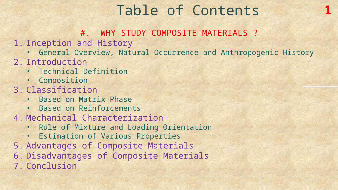
Table of Contents 1
#. WHY STUDY COMPOSITE MATERIALS ?1. Inception and History
• General Overview, Natural Occurrence and Anthropogenic History2. Introduction
• Technical Definition• Composition
3. Classification• Based on Matrix Phase• Based on Reinforcements
4. Mechanical Characterization• Rule of Mixture and Loading Orientation• Estimation of Various Properties
5. Advantages of Composite Materials6. Disadvantages of Composite Materials7. Conclusion
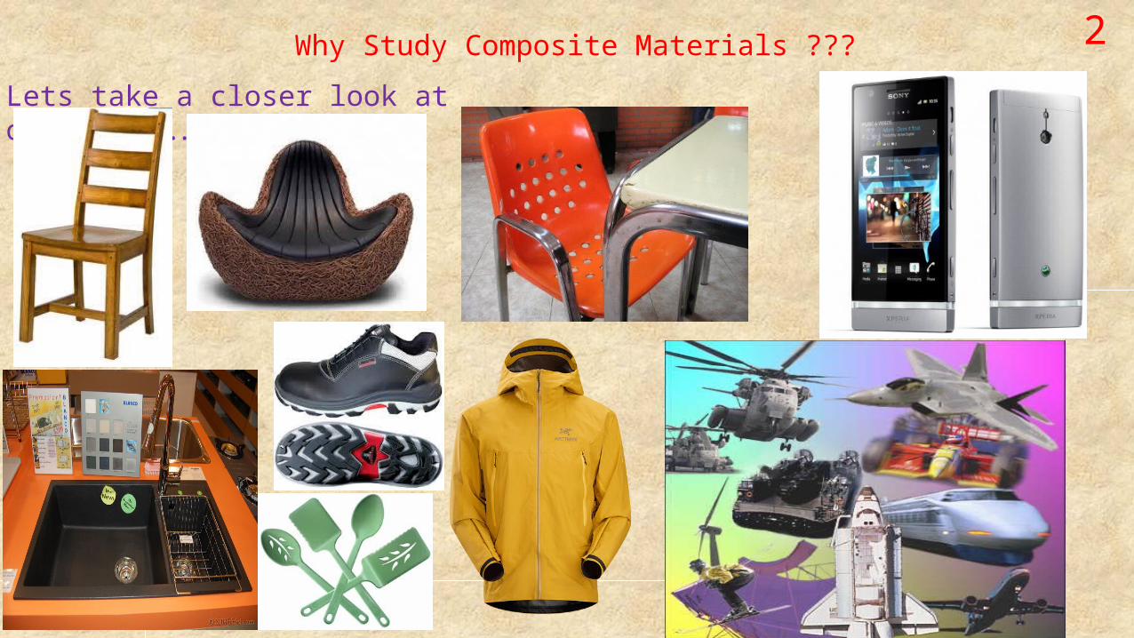
2Why Study Composite Materials ???
Lets take a closer look at our lives….

3Why Study …contd.
• Composites make a great proportion of most of the materials we use in our daily lives
• The use is ever increasing which makes it a must to understand and explore these materials
THAT’S WHY …….
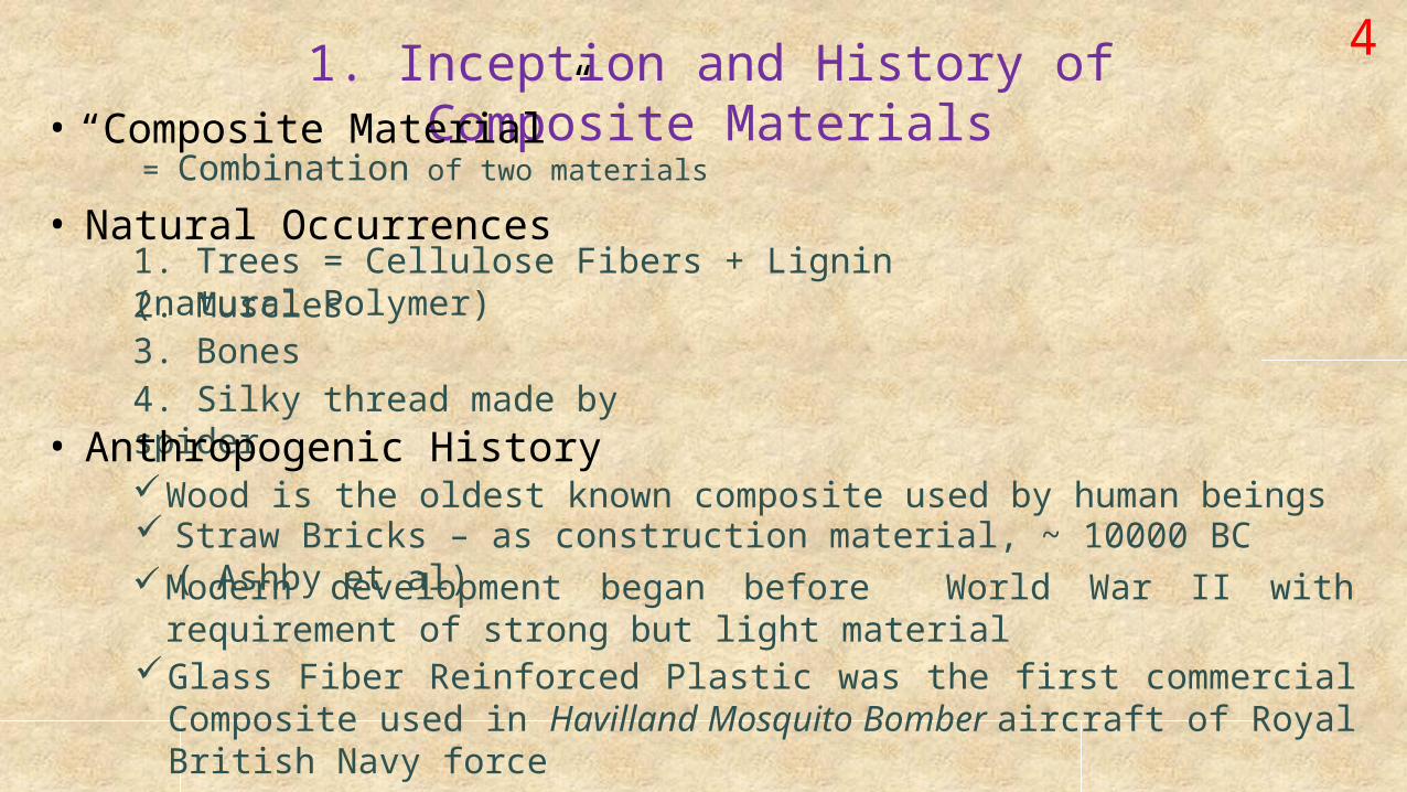
1. Inception and History of Composite Materials
4
• “Composite Material”= Combination of two materials
• Natural Occurrences1. Trees = Cellulose Fibers + Lignin (natural Polymer)2. Muscles3. Bones4. Silky thread made by spider• Anthropogenic HistoryWood is the oldest known composite used by human beings Straw Bricks – as construction material, ~ 10000 BC ( Ashby et al)Modern development began before World War II with requirement
of strong but light materialGlass Fiber Reinforced Plastic was the first commercial Composite
used in Havilland Mosquito Bomber aircraft of Royal British Navy force
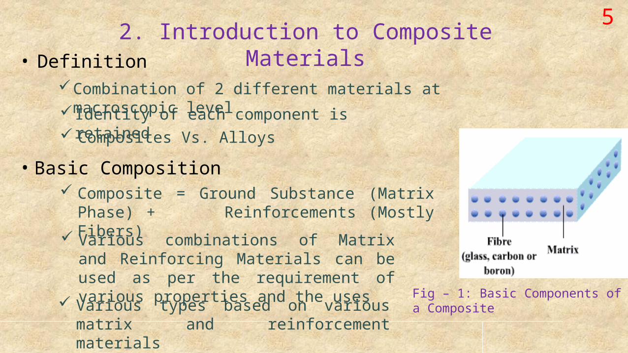
2. Introduction to Composite Materials
5
• DefinitionCombination of 2 different materials at macroscopic
level Identity of each component is retained Composites Vs. Alloys
• Basic Composition Composite = Ground Substance (Matrix
Phase) + Reinforcements (Mostly Fibers)
Fig – 1: Basic Components of a Composite
Various combinations of Matrix and Reinforcing Materials can be used as per the requirement of various properties and the uses Various types based on various matrix and reinforcement materials
63. Classification of Composite
MaterialsA. Based on Matrix Phase: Polymer/Metal/Ceramic
1. Polymer Matrix Composite, PMC • Matrix is made from a Polymer like Resins
• The first commercial composite, Glass Fiber, was a PMC made with Phenolic Resin
• May be a. Thermosetting ~ Epoxy Resin OR b. Thermoplastic ~ Polycarbonate, PVC, Nylon,
Polystyrene
Light Weight Easy Processing Excellent Mechanical Properties Extensive use in Automobile and
Aeronautical Industries2. Metal Matrix Composite, MMC
• Use metals like Aluminum, Magnesium, Iron, Cobalt etc. as matrix phase Provide additional Strength, Fracture Toughness and Stiffness than PMC Popular in Mobile Phone industries
3.A Classification/Matrix Phase … contd.
3. Ceramic Matrix Composite, CMC• Use Ceramic materials as the matrix phase and reinforce with
short fibers derived from Silicon Carbide, Boron Nitride, etc. High Melting Point Stability at elevated temperature ( ~ 1500 oC ) Corrosion Resistant High Compressive Strength
7
Favorite choice for working in high temperature environment
X However they are quite brittle compared to PMCs
B. Classification Based on Reinforcement Materials: Fibers/Particulates/Flakes/Whiskers1. Fiber Reinforcement
• Fibers made from various materials are placed within the matrix phase to form a composite of desired strength/properties
• Fibers form the major load carrying element and are most common reinforcement
3.B Classification/By Reinforcement/Fibers …. Contd. 83.B.1 Fiber Reinforcement:
Types of Fiber Reinforcement
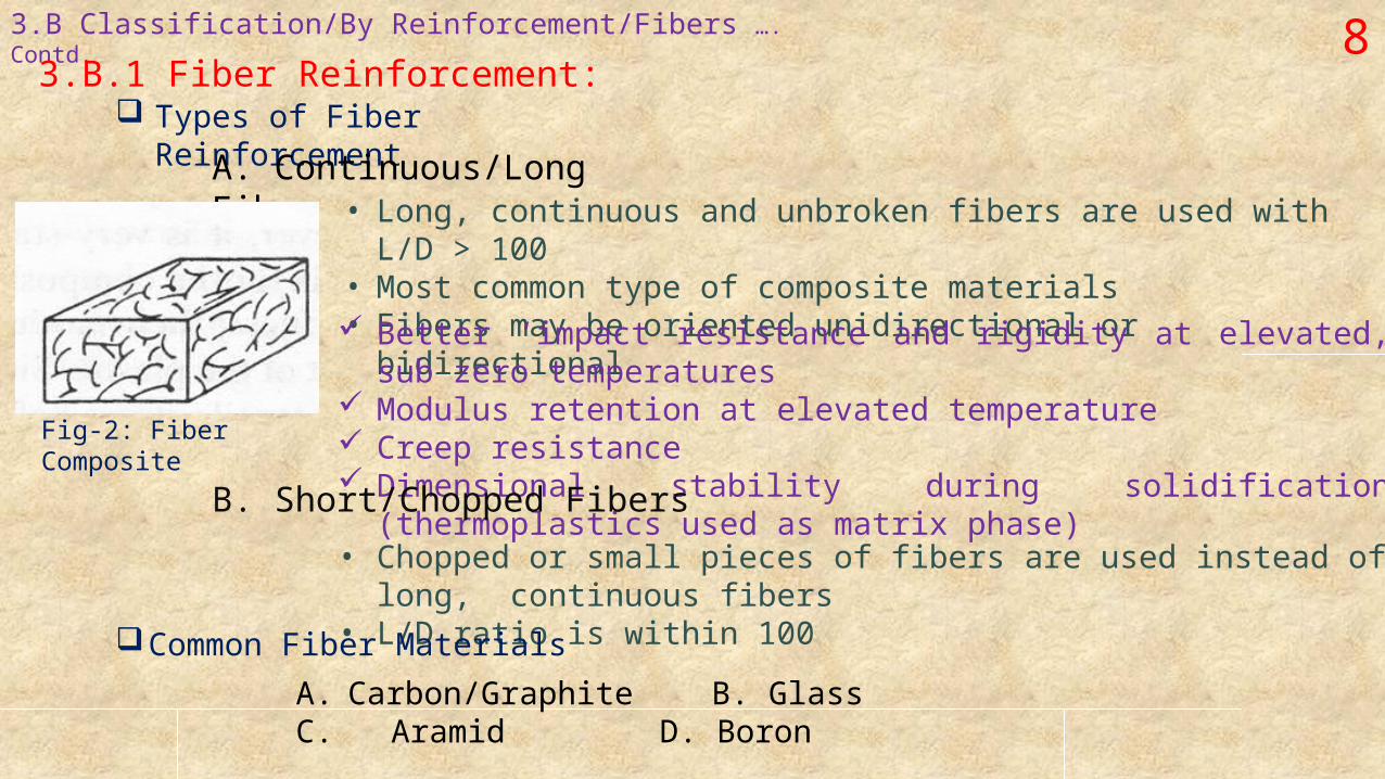
A. Continuous/Long Fiber• Long, continuous and unbroken fibers are used with L/D > 100• Most common type of composite materials• Fibers may be oriented unidirectional or bidirectional Better ‘impact resistance and rigidity at elevated, sub zero
temperatures Modulus retention at elevated temperature Creep resistance Dimensional stability during solidification (thermoplastics used
as matrix phase)B. Short/Chopped Fibers
• Chopped or small pieces of fibers are used instead of long, continuous fibers
• L/D ratio is within 100Common Fiber Materials
A. Carbon/Graphite B. Glass
C. Aramid D. Boron
Fig-2: Fiber Composite
3.B.1 Classification/Based on Reinforcement/Fibers/ Common Fiber Materials……. Contd. 9
A. Carbon/Graphite Fibers• Fibers are made from carbon/graphite material, commonly derived from
Polyacrylonitrile Excellent fatigue resistance and do not undergo stress rupture like glass fibers
High electrical conductivity, due to conductive nature of Carbon, thus used for applications requiring good electrical propertiesB. Glass Fiber
• Glass is the most common reinforcement material for PMC• Common variants are E-glass, R-glass, S-glass, D-glass, ECR-glass etc.• Configuration may be Roving, Sheet Moulding, Woven Roving, Chopped
Strand Mat etc. High Tensile StrengthX Lower Modulus compared to other fibersC. Aramid Fiber • Kevlar is a common aramid fiber
composite Highest strength to weight ratio among all commercial composites Similar tensile strength but at least twice modulus compared to glass
fibers High ToughnessX Lower compression strength, poor adhesion to matrix
10
3.B.1 Classification/By Reinforcement/Fiber/Fiber Materials ….. Contd.
D. Boron Fibers
• Has been in use much before the use of Carbon fibers began• High cost led to gradual reduction in their except for specific
purposes Similar tensile strength to glass fibers but very high modulus, up to 5 times higher
Composite has higher stiffness3.B.2 Particulate Reinforcement
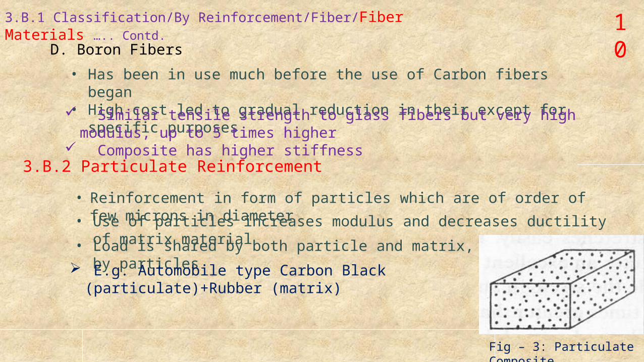
• Reinforcement in form of particles which are of order of few microns in diameter• Use of particles increases modulus and decreases ductility of matrix material• Load is shared by both particle and matrix, majority by particles E.g. Automobile type Carbon Black (particulate)+Rubber
(matrix)
Fig – 3: Particulate Composite
113.B. Classification/By Reinforcement ….Contd.
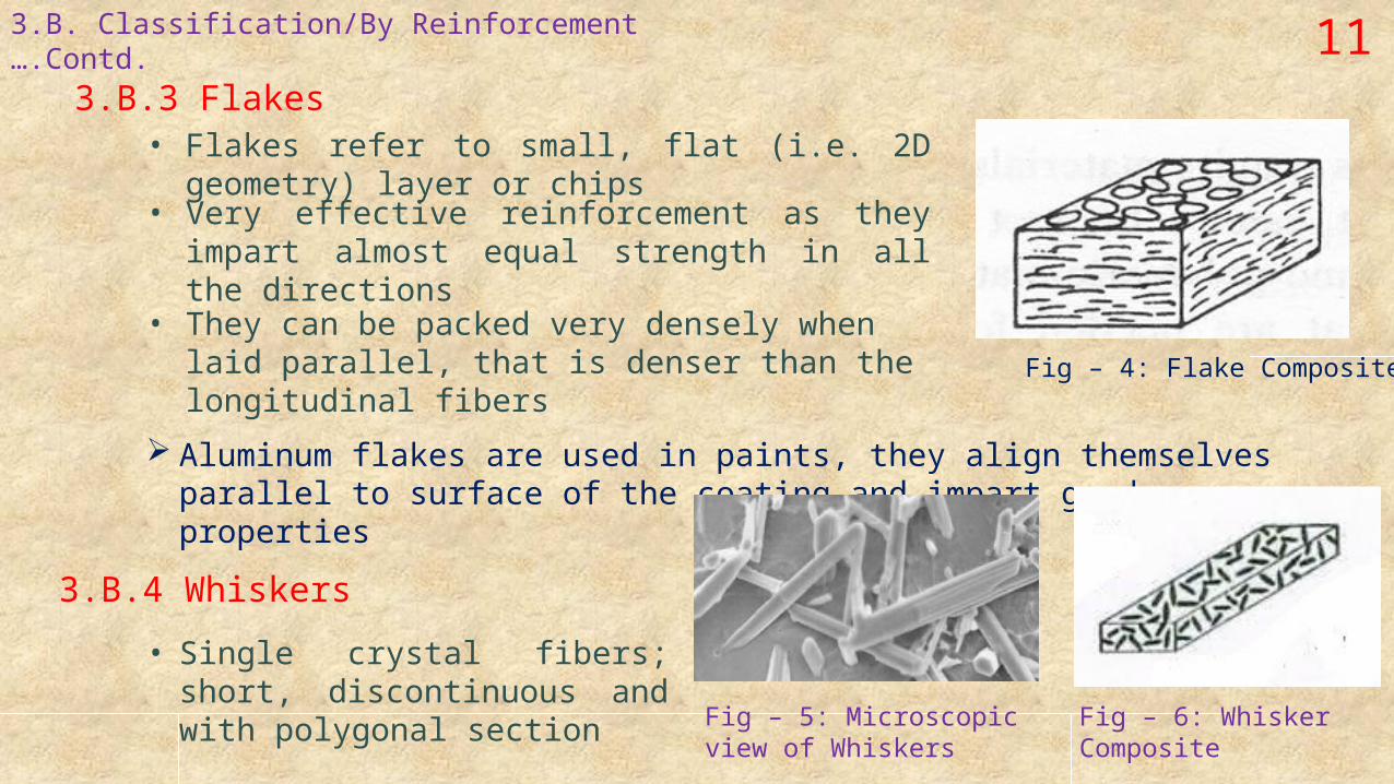
3.B.3 Flakes
Fig – 4: Flake Composite
• Flakes refer to small, flat (i.e. 2D geometry) layer or chips
• Very effective reinforcement as they impart almost equal strength in all the directions
• They can be packed very densely when laid parallel, that is denser than the longitudinal fibers
Aluminum flakes are used in paints, they align themselves parallel to surface of the coating and impart good properties
3.B.4 Whiskers
• Single crystal fibers; short, discontinuous and with polygonal section Fig – 5: Microscopic view
of WhiskersFig – 6: Whisker Composite
124. Mechanical Characterization : Composites4.1 Introduction
• Estimation of mechanical properties of composite is a bit complex compared to metals as they are anisotropic and the properties vary with directions• Structural analysis involves more parameters (like Stiffness/Strength Constants) than the analysis of metals.
• Mechanical characterization of composites is still under development, with many existing methods under debate.
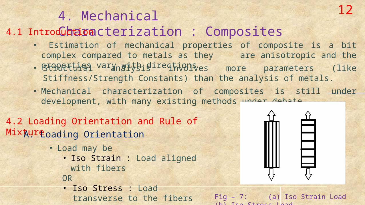
4.2 Loading Orientation and Rule of MixtureA. Loading Orientation
• Load may be• Iso Strain : Load aligned with
fibersOR• Iso Stress : Load transverse to
the fibers Fig – 7: (a) Iso Strain Load (b) Iso Stress Load
134.2 Mechanical Characterization …. Contd.
B. Rule of Mixture
• It’s an approach to estimate the mechanical properties of composite materials• Property of composite is the volume weighed average of the properties of the constituents matrix and the dispersed phases
• Some of the properties may depend on loading direction and vary for Iso Strain and Iso Stress conditions, while other properties are same for both the loading conditions
4.3 Estimation of various Mechanical Properties of the Composites
1. Density
dc = dm . Vm + df . Vf
dc ,dm,df – densities of the composite, matrix and dispersed phase respectively; Vm ,Vf – volume fraction of the matrix and dispersed phase respectively.
144.3 Mechanical Characterization/Mechanical Properties …… Contd.
2. Coefficient of Thermal ExpansionA. Iso-Strain/Parallel to fibers
αc =( αm . Em .Vm + αf . Ef . Vf ) / (Em . Vm + Ef Vf )
αc , αm , αf – Coefficient of thermal expansion of composite in longitudinal direction, matrix and dispersed phase (fiber) respectively; Em , Ef – Modulus of elasticity of matrix and dispersed phase (fiber) respectively. B. Iso-Stress/Transverse to Fibers
αct = (1+μm) αm . Vm + αf . Vf
μm - Poisson’s ratio of matrix αct – Coefficient of thermal expansion in transverse direction
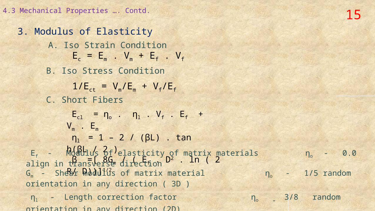
154.3 Mechanical Properties …. Contd.
3. Modulus of ElasticityA. Iso Strain Condition
Ec = Em . Vm + Ef . Vf
B. Iso Stress Condition
1/Ect = Vm/Em + Vf/Ef
C. Short Fibers
Ecl = ηo . ηl . Vf . Ef + Vm . Em
ηl = 1 – 2 / (βL) . tan h(βL / 2 ) β =[ 8Gm / ( Ef . D2 . ln ( 2 R/ D))]1/2
Ef - Modulus of elasticity of matrix materials ηo - 0.0 align in transverse directionGm - Shear modulus of matrix material ηo - 1/5 random orientation in any direction ( 3D )
ηl - Length correction factor ηo - 3/8 random orientation in
any direction (2D) L - Fibers length ηo - ½ bi- axial parallel to the fibers D - Fibers diameter ηo - 1.0 unidirectional parallel to the fibers 2R - Distance between fibers ηo - Fibers orientation distribution factor
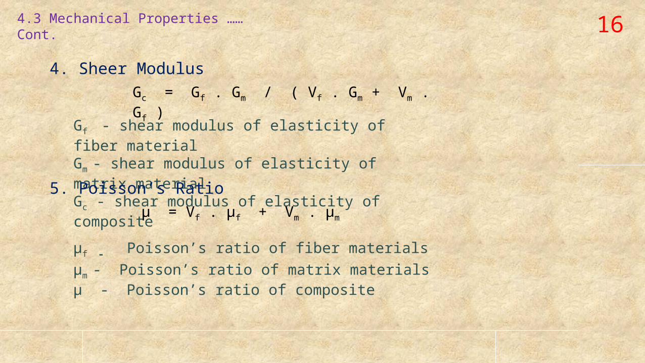
164.3 Mechanical Properties …… Cont.
4. Sheer ModulusGc = Gf . Gm / ( Vf . Gm + Vm . Gf )
Gf - shear modulus of elasticity of fiber materialGm - shear modulus of elasticity of matrix materialGc - shear modulus of elasticity of composite
5. Poisson’s Ratio µ = Vf . µf + Vm . µm
µf - Poisson’s ratio of fiber materials
µm - Poisson’s ratio of matrix materialsµ - Poisson’s ratio of composite
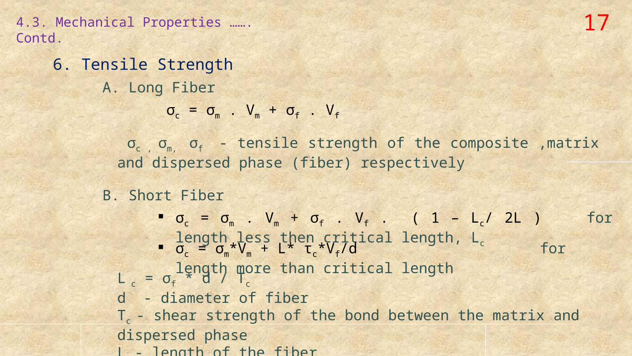
174.3. Mechanical Properties ……. Contd.
6. Tensile StrengthA. Long Fiber
σc = σm . Vm + σf . Vf
σc , σm, σf - tensile strength of the composite ,matrix and dispersed phase (fiber) respectively
B. Short Fiber
σc = σm . Vm + σf . Vf . ( 1 – Lc/ 2L ) for length less then critical length, Lc σc = σm*Vm + L* τc*Vf/d for length more than critical length
L c = σf * d / Tc
d - diameter of fiberTc - shear strength of the bond between the matrix and dispersed phase L - length of the fiber
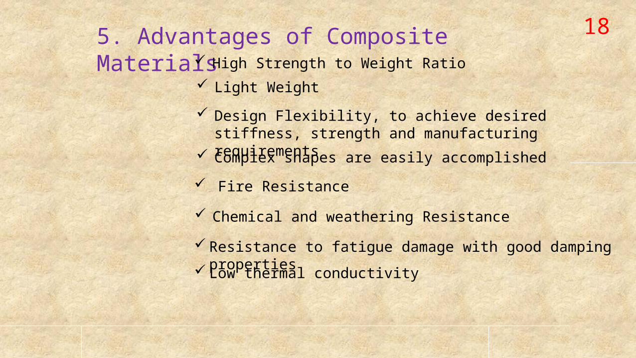
185. Advantages of Composite Materials High Strength to Weight Ratio
Light Weight
Design Flexibility, to achieve desired stiffness, strength and manufacturing requirements
Complex shapes are easily accomplished
Fire Resistance
Chemical and weathering Resistance
Resistance to fatigue damage with good damping properties Low thermal conductivity
195. Disadvantages
High Manufacturing Cost. A typical finished composite may cost in between 10-15 times (or even more) the cost of material being used. Synthetic fibers have low melting point and thus high temperature operation is not feasible for those type of composite Repairs of composites is very difficult and complicated, unlike metal based components
Sometimes, critical flaws and cracks in the composite structure may go unnoticed
6. Conclusion• A field of heave research and development
• Development of new types and obtaining the desired properties is the main focus
• Attempts are being made to reduce the manufacturing cost

THANK YOU !!!