Embed Size (px)
Citation preview
1
Composite preforming defects: A review and a classification.
Rym Azzouza, Samir Allaouia, Raphael Moularta
a ITheMM (EA 7548), University of Reims Champagne-Ardenne, EiSINe, Campus Sup Ardenne, BP50028, 08005,
Charleville Mézières Cedex, France.
Corresponding author: Samir Allaoui: [email protected]
Abstract:
Advancing in the process of extending the use of composites for structural parts applications, it is inevitable
to work on complex shapes. That is the main reason why understanding the complex forming mechanisms and
the factors put into play during the process of composite materials is a major interest for both pre-impregnated
forming and dry fabric preforming. Thus, the apdpearance of defects is a major concern and predicting their
appearance for optimal product quality is the priority. A great number of authors showed that defects degrade
the overall performance of the composite by creating local heterogeneities. Many factors can initiate these
defects. This article is an assembly of the development of the literature on this subject. It is an attempt to
provide a description for each defect and a classification order following the scale, the behavior mechanisms,
the appearance plan. This will help to converge toward an identification of the defects manifesting during the
composite forming.
Keywords: Defects, Forming, Fabrics/textiles, Yarn
Acknowledgments:
The authors gratefully acknowledge the Chair of MATUR for his finnacial support. The chair MATUR is co-
financed by the Région Grand Est (France) (grant number D201507798), the European Union (grant number
D201507799) and UIMM (Partners convention n°13-2015)
I. INTRODUCTION
For the last decades, composite materials are more in demand in many industries thanks to their interesting
mechanical properties, the possibility of functionalizing them and their good adaptability according to the
environment they are used in. To harvest their fullest potentials, one of the challenges to overcome is to
master the forming process. If we look at the example of metal forming, it has long been guided by a
normalized forming limit diagrams (FLD) or curves. Among the first authors who proposed such approach,
we find Hosford and Caddell (1983) who proposed a graphic curves describing the strain limit of the metal
sheet in each direction. These forming limit diagrams (FLD) [1] allow determining the formability to know
whether a given geometry can be obtained with a specific material. Doing the same for the composite
materials is a challenge because having a great variety of composites types along with the highly
2
heterogeneous properties make it hard to cover all the variabilities such as the weaving pattern and
parameters, the nature and the material of the fiber, the yarn width, treatment undergone such as sizing,
conditioning, stress history ... So, it is mandatory to understand the composite behavior during forming. The
complexity of the reinforcement brings forwards numerous defects that manifest on different levels. Every
factor such as the reinforcement type (fabric type, number of layers, orientation …), the process type (punch
and die, global or sequential stamp, diaphragm …), settings (speed, tool, pressure, blank holders…) and the
geometry (hemisphere, square, double dome, prism …) can influence the outcome of the preform quality.
The effort has been put to understand these defects and the cause of their appearance [2–7] along with
suggesting solutions to avoid them [8–11]. It was either manipulate one of these factors or add a new one to
oppose the effect of the first. For each application, these defects have been investigated individually. So until
today there is no forming limit norm or guide that standardize the forming process for composites. Some
authors attempted to preform each fabric with a similar protocol [12] using different type of setting and others
conducted benchmark of forming geometries on the appearance of defects [13]. These studies have proven
that building a standardized forming limit diagram for composite materials is a challenge. This why a lot of
efforts are being put on working on developing numerical simulations [14–16] to determine the feasibility of
the forming, to narrow down the factors, to lower the possibilities and avoid unnecessary experimental work.
The numerical simulations are a complementary work done before conducting the experimental forming, for
side by side verification and validation [17–21]. Alone, they cannot portray all the factors that take part in the
preforming, it may show great accuracy but, it cannot be an alternative for the experimental results.
The preforming of a composite can be distinguished into 2 types, prepreg forming and the dry fabric
preforming, where the defects play a great role in degrading the mechanical properties and creating local
heterogeneities and weaknesses that will initiate the failure. To assess the gravity of the defects, many studies
have investigated how a defect affects composite mechanical behaviors such as the effect of out of plane
wrinkles and waviness on quasi-static behavior [22–27] or the fatigue performance [28, 29], the effect of in-
plane fiber misalignment [30, 31] and out of plane waviness [30], the effect of voids on the composite’s limit
under compression loads [31] and the effect of the shear angle variation under compression [32]. The
literature highlighted that multiple forming defects, on different scales, degrade the mechanical properties
depending on their severity hence the importance to predict their appearance. For that, the composite's
behavior mechanisms and the multiple factors taking a part in the forming process must be investigated to
understand the role of each on the defect appearance. Until now the forming defect studies have shared many
common conclusions on this aspect but they did not share the same vocabulary and definition in reference to
each of the defects. In this paper, we propose an overview of the different defects appearing during the
preforming process that are listed in the literature so far, the different mechanisms associated with their
appearance and then a classification depending on their scale (Multi-layer, mono-layer, and down to the yarn
defects). This can be the first step to create a composite forming defects manual.
3
II. PREFORMING DEFECTS
The manifestation of defects during preforming of dry fabric or prepreg forming is a complex process and a
result of many factors, either originated from the composite itself (the fabric properties, dimensional or
mechanical …) or the preforming procedure (the preform shape, speed, pressure …). All these factors should
be deeply investigated as they hold the key to understand the phenomena behind the appearance of the
defects. Hence, any defect will disturb the homogeneity of the structure creating local variation in the
mechanical properties of the composite. Therefore, they are deeply investigated in numerous works in the
literature starting from forming a single layer as it is the simplest to study then to preforming a stack of multi-
layered fabrics adding new variables to the picture. The vocabulary used in the literature is unstandardized
from an author to another, all through this article, each time we use the exact term used by an author it will be
mentioned between brackets. We propose a defect classification depending on the scale of their appearance:
monolayer, multilayer and the yarn/ filament scale. Following the description and definition of each one
provided, we can distinguish defects generated due to out-of-plane deformations, and in-plane deformations.
The ‘plane’ referring to the plane in which the fabric takes for its final form after the preform shaped into the
geometry that we are aiming to obtain in the final results. Then defects go beyond the change of the fabric
form or pattern to appearing on a smaller scale on the yarns or filaments of the fiber.
1. Monolayers pre-form defects:
A major number of the studies on the preform of composite materials have been done on a single layer,
mostly on forming dry fabric and rarely on Prepreg composites. They used different simple geometries and
complex geometries dedicated to specific applications. Using a single layer, defects appear on the level of a
single fabric form as an out-of-plane defect or it affects its pattern distribution as in-plane defects.
a) Out of plane deformation:
One of the first studies was by Tam [33] concentrating solely on the kinematic analysis to form a fiber sheet
into a geodesic. Tam highlighted that it is important for the fabric to allow the in-plane shear to prevent the
out-of-plane bending, “buckling”, where he identified the health of the forming by characterizing the
magnitude of the shearing angle in the critical, highly curved areas. Then, he determined that the appearance
of the out-of-plane deformation depends on the shear angle. This angle is the rotation that the fabric is
subjected to, comparing to its initial direction. In the same period, Christie et al.[34] has attributed the out-of-
plane deformation to the effect of the compression (negative tension). When this compression occurs in a
certain location of the fiber alignment, the fabric buckles in an out-of-plane deformation. They concluded that
this phenomenon depends purely on the stress distribution in the concerned area, which is very complex in the
case of composite forming, highlighting that building a forming limit diagram like for metal sheet forming
dictated by Hosford and Caddell in 1983 is a challenge. This limit is a criterion defined by the formability,
which is the ability of the fabric to take the shape and form of defined geometry and undergo plastic
4
deformation without creating any damages [35], which is measured by conducting different tests. The higher
the curves and the details, the higher the formability is required.
Yu et al. [36] identified the different deformation modes of fabrics: transverse compression, out-of-plane
bending, in-plane tension and in-plane shear. They suggested that by conducting these tests we can determine
the formability of the fabrics. They used different types of fabrics and measured their shearing angles and
their behavior in different deformation loads experimentally. They concluded that the formability depends
strongly on the fabric type that is why there were authors who build on their statement and investigated the
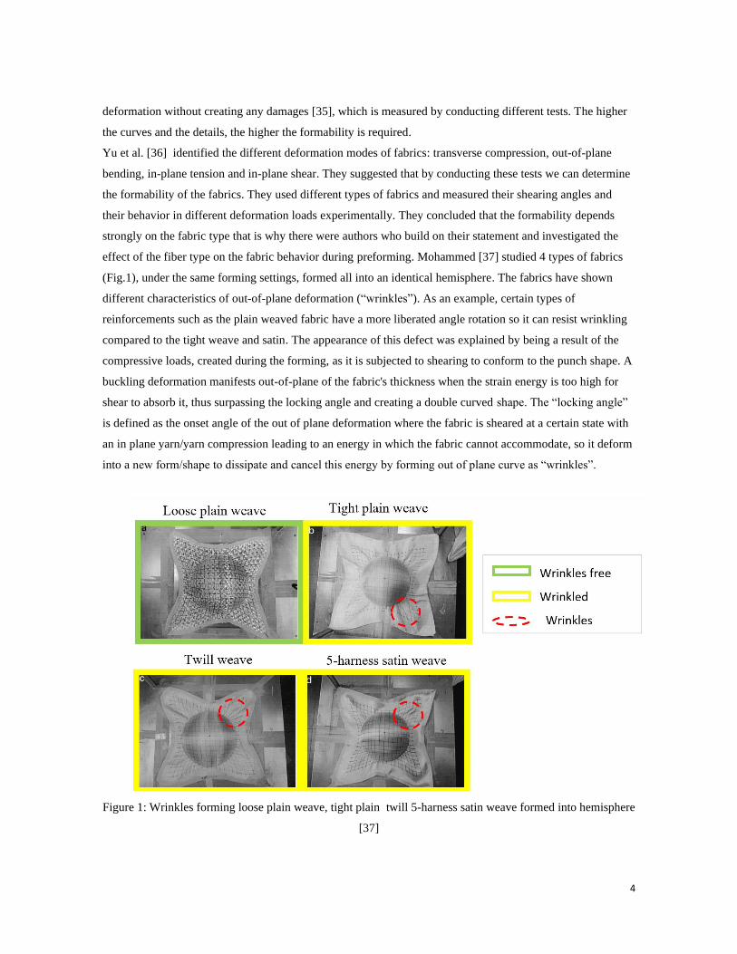
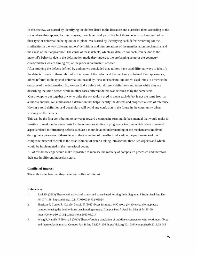
effect of the fiber type on the fabric behavior during preforming. Mohammed [37] studied 4 types of fabrics
(Fig.1), under the same forming settings, formed all into an identical hemisphere. The fabrics have shown
different characteristics of out-of-plane deformation (“wrinkles”). As an example, certain types of
reinforcements such as the plain weaved fabric have a more liberated angle rotation so it can resist wrinkling
compared to the tight weave and satin. The appearance of this defect was explained by being a result of the
compressive loads, created during the forming, as it is subjected to shearing to conform to the punch shape. A
buckling deformation manifests out-of-plane of the fabric's thickness when the strain energy is too high for
shear to absorb it, thus surpassing the locking angle and creating a double curved shape. The “locking angle”
is defined as the onset angle of the out of plane deformation where the fabric is sheared at a certain state with
an in plane yarn/yarn compression leading to an energy in which the fabric cannot accommodate, so it deform
into a new form/shape to dissipate and cancel this energy by forming out of plane curve as “wrinkles”.
Figure 1: Wrinkles forming loose plain weave, tight plain twill 5-harness satin weave formed into hemisphere
[37]
5
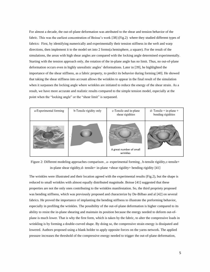
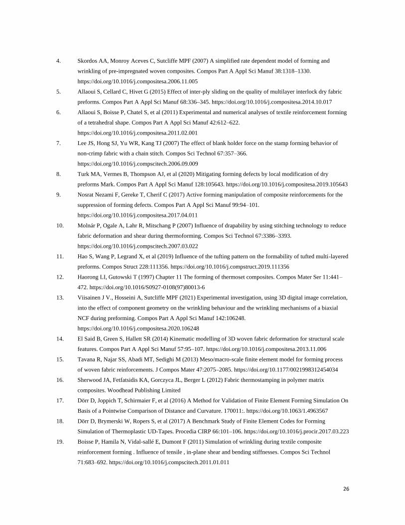
For almost a decade, the out-of-plane deformation was attributed to the shear and tension behavior of the
fabric. This was the earliest concentration of Boisse’s work [38] (Fig.2) where they studied different types of
fabrics: First, by identifying numerically and experimentally their tension stiffness in the weft and warp
directions, then implement it to the model set into 2 forms(a hemisphere, a square). For the result of the
simulations, the areas with high shear angles are compared with the locking angle determined experimentally.
Starting with the tension approach only, the rotation of the in-plane angle has no limit. Thus, no out-of-plane
deformation occurs even in highly unrealistic angles’ deformations. Later in [39], he highlighted the
importance of the shear stiffness, as a fabric property, to predict its behavior during forming [40]. He showed
that taking the shear stiffness into account allows the wrinkles to appear in the final result of the simulation
when it surpasses the locking angle where wrinkles are initiated to reduce the energy of the shear strain. As a
result, we have more accurate and realistic results compared to the simple tension model, especially at the
point when the “locking angle” or the “shear limit” is surpassed.
Figure 2: Different modeling approaches comparison , a- experimental forming , b-tensile rigidity,c-tensile+
in-plane shear rigidity,d- tensile+ in-plane +shear rigidity+ bending rigidity [41]
The wrinkles were illustrated and their location agreed with the experimental results (Fig.2), but the shape is
reduced to small wrinkles with almost equally distributed magnitude. Boisse [41] suggested that these
properties are not the only ones contributing to the wrinkles manifestation. So, the third propriety proposed
was bending stiffness, which was previously proposed and characterize by De-Bilbao and al [42] on several
fabrics. He proved the importance of implanting the bending stiffness to illustrate the preforming behavior,
especially in profiling the wrinkles. The possibility of the out-of-plane deformation is higher compared to its
ability to resist the in-plane shearing and maintain its position because the energy needed to deform out-of-
plane is much lower. That is why the first form, which is taken by the fabric, to alter the compressive loads in
wrinkling is by forming a double-curved shape. By doing so, the compressive strain energy is dissipated and
lowered. Authors proposed using a blank holder to apply opposite forces on the yarns network. The applied
pressure increases the threshold of the compressive energy needed to trigger the out-of-plane deformation,
6
which decreases the risk and delay the wrinkles formation until angles beyond the locking angle . It is also
proven that the properties of the wrinkles, such as number and magnitude, depend on the bending stiffness of
the fabric [43][44] where the magnitude of the wrinkles increases along with the bending stiffness. So to
oppose the bending energy from acting up and triggering the out of plane deformation, it could be nullified by
adding opposing tensile energy into the picture, transferring all the energy into shearing. So we can have a
delayed onset of the out-of-plane deformation with shear angles being higher than the locking angle, so we
have a delay in the appearance of the defect.
So, adding the bending stiffness to the tension, the locking angle is not a criterion for the existence of the
wrinkles. This statement was subsequently backed up by the result found in other studies where the onset of
the wrinkles can happen at higher than the locking angle [37] or be avoided even with widely exceeded
locking angle [45]. This questioning the certainty of the first definitions of the locking angle in 1993 by A.C
Long [46] and later in 1998 by J.Wang [47], where it was measured by an experimental shear test (picture
frame and bias test) assuming that there is purely in-plane shearing, whereas the appearance of wrinkles is
driven by a strong coupling between shear, tension and bending behaviors. Many studies proved that the
locking angle is relative to the process, depending on all the different properties mentioned above, coupled to
shape the result accordingly. Thus, one by itself is not enough to set the deformation mechanism during the
preforming. So the idea suggested earlier during the ’90s by Yu et al. [36] to determine the formability by
performing separate tensile, bending and shear experimental tests is not enough, because during forming, the
fabric is subjected to all these modes of deformations at the same time and they can be coupled. As a result,
some of these modes may magnify or cancel the effect of each other, so they play a major role in determining
the final shape, state and location of the out-of-plane deformation. Thus, independent mechanical testing is
not enough to cover the full picture of the forming behavior. That is why, to predict the formability of a
structure, implementing the mechanical properties into a numerical model, seems the right solution. But, to
be so, it has to cover all the variables during the forming, from the forming process setting to the fabric
properties, the form geometry, etc., which is in reality very complicated due to the interfering of different
factors and acting at the same time. So the numerical simulation results until this day are accurate and
satisfying in term of presenting the out of plane deformation and predicting their appearance and profile
(magnitude and number) .
There has been almost no major addition since later the authors focused their efforts on investigating which
factor is associated with each deformation mode aiming to understand and prevent the out-of-plane
deformation from manifesting. One of the methods is to optimize the blank holder pressure, used as a tool to
maintain the sheet’s initial position during forming. The blank holders apply in-plane tension, which opposes
the compression stress that is one of the main causes of the initiation of wrinkling. Authors like Allaoui
[6][45], on interlock shaped into a prism and tetrahedral, and J.S.Lee [7], with NCF shaped into a hemisphere,
studied thoroughly the effect of varying the blank holder pressure, even with different fabrics type and
7
geometries. It has been proven that the blank holder plays a major role in delaying of the wrinkling helping to
suppress the compression stress.
The authors also worked on the variation of geometries and their influence on the out-of-plane deformations.
They have found that when the geometry holds a highly curved shape or small radii, it creates additional
stress in that specific local area that forces the fabric to adapt to the distinctive form of the geometry. There is
a limit to this adaptability [48], it can end up with wrinkles [8, 45] or in rare cases with bridging [49–51]: it is
when the fabric is not able to copy the radii of a corner of the geometry with it will maintain a bigger radius,
thus a void between the shape and the fabric in this local area occur. It is also found that the wrinkling can be
delayed by using the punch and die vacuum bag, which creates normal compressing making the energy
needed to deform out-of-plane more important, thus resisting and maintaining its plane form for longer. But
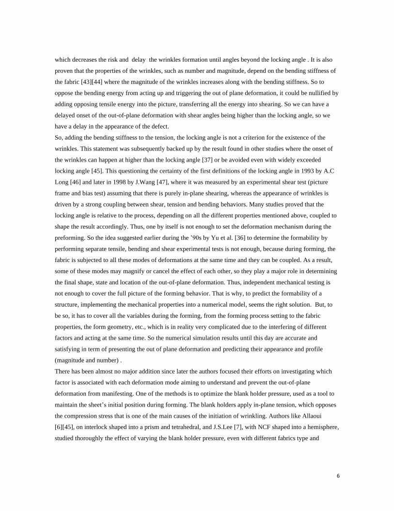
these solution has to be conducted with caution because by applying excess pressure in the case where the
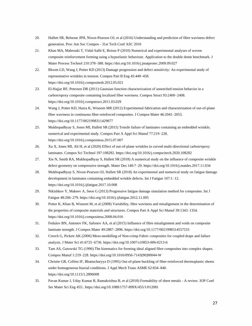
wrinkles are already formed, we can create “folds”. In fact, after the forming of the wrinkles if any pressure is
applied, one of the two sides of the curved wrinkles will fall on the second and create a local fold with 2 more
extra layers, so further complicated defects (Fig.3) [49][4].
Figure 3: Details of the occurrence of wrinkling turning into folds [4]
Even though the pre-impregnated has rarely been studied a single layer [4, 52], the out of plane deformation
mechanism is identical with a difference due to the presence of the resin which, when heated, acts as a
lubricant due to its viscosity leading to reduce fiber / fiber friction. This lead to a decrease of the stress state of
the reinforcement, and therefore potential defects, as the friction is the predominant mechanism of the fabric
behaviors (shearing, lateral compaction, bending, etc.), due to its heterogeneity, where the movements of
fibers, yarns or ply occur. Putting on the spotlight another parameter investigated, the friction manifested
between the tool and the reinforcement [53][54][55], which was not taken into consideration before. This
Wrinkles ➔ Folds
8
friction creates an adding tangential load on the fabric, which should be taken into account for how it can
contribute to wrinkles formation.
b) In-plane deformation:
In addition to the out-of-plane deformation, the fabric has the liberty of an in-plane movement. For an in-
plane defect, the fabric pattern changes leading to local heterogeneity. When a single layer is subjected to in-
plane strain, the pattern is affected to adapt the shape and the risk of defects is high in many cases (depending
on the geometry, the fabric, and the process settings). Laroche [56] was amongst the first that explored the
effect of the shear angle “variation on the thickness distribution”, which can be considered as a defect while
testing six different types of fabrics. The preform geometry is highly curved on top with a radius of 60 mm.
The author developed a geometrical equation that represents the thickness increase due to the shear angle in
one cell, using the volume conservation assumption. This study showed that the final thickness can exceed 1.4
of the original fiber thickness in a high sheared zone. This variation in fiber density creates heterogeneity in
mechanical properties. This form of defect is due to the shearing behavior that manifests by yarns rotation.
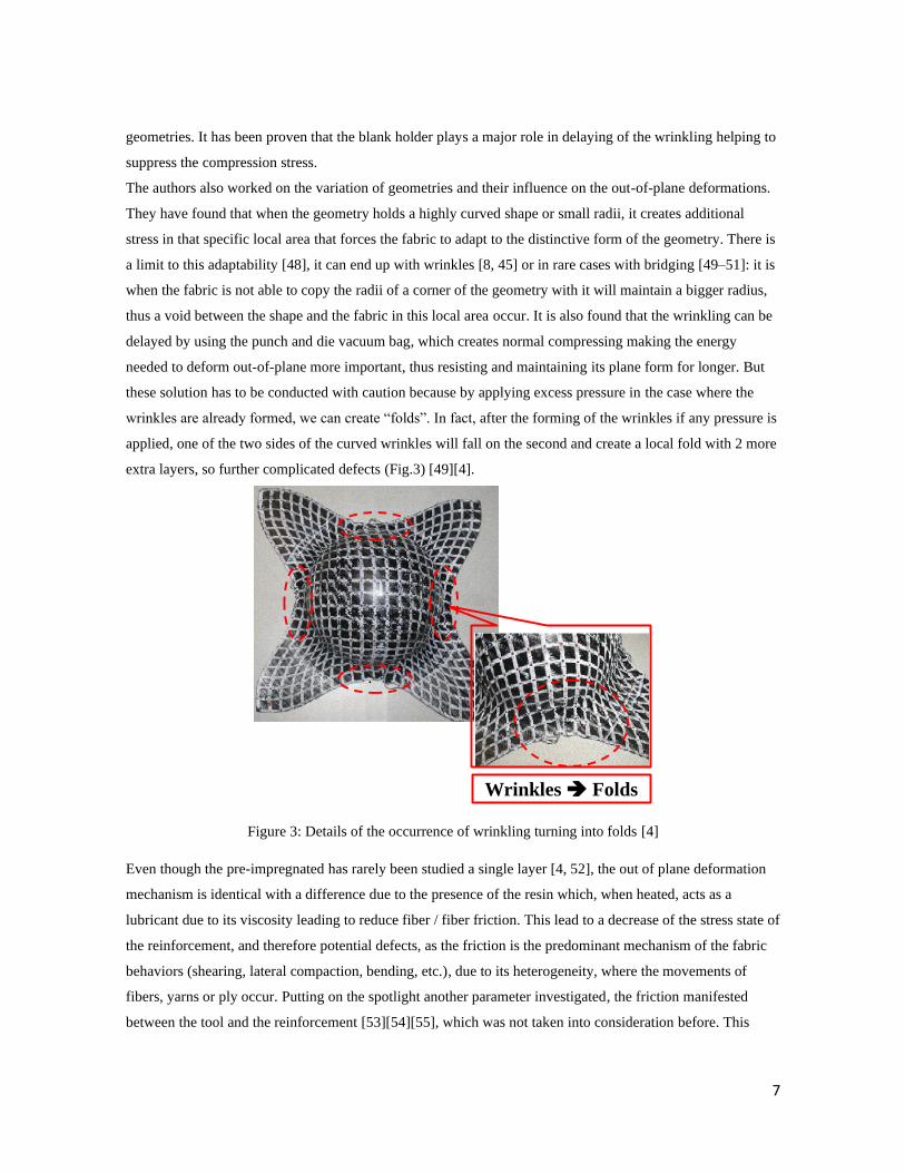
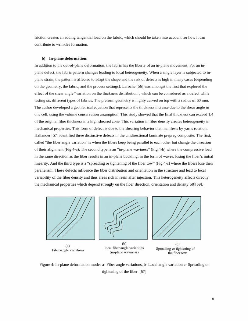
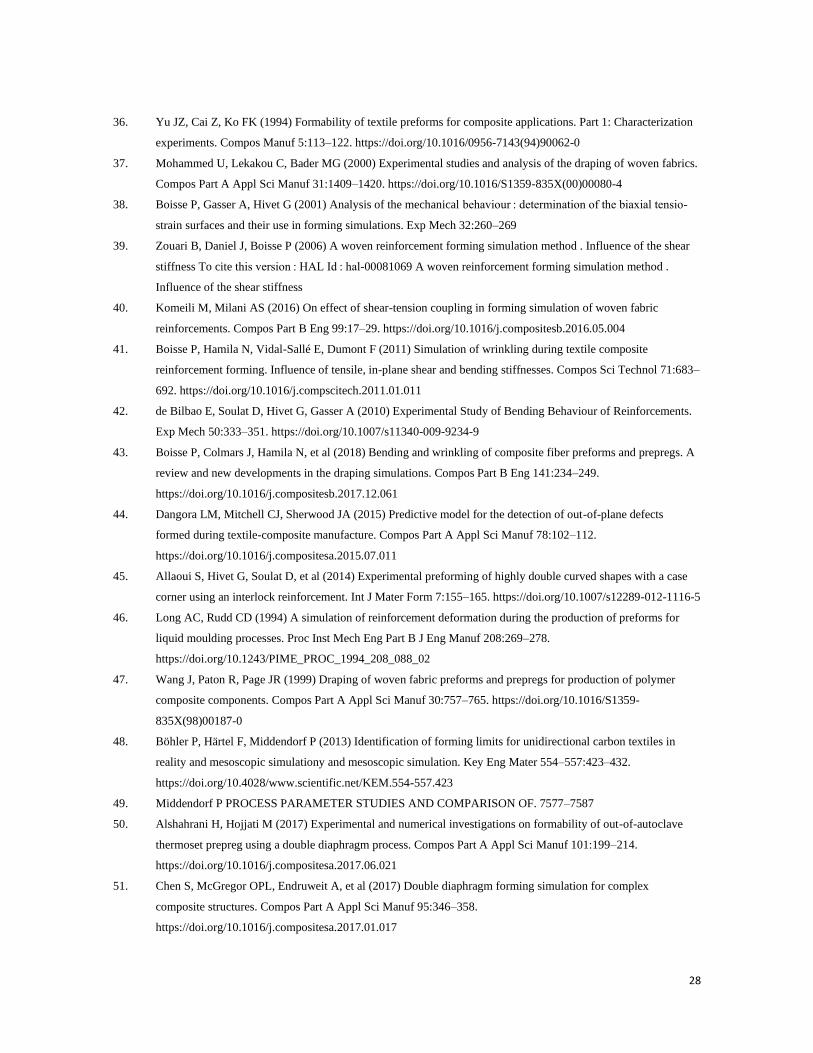
Hallander [57] identified three distinctive defects in the unidirectional laminate prepreg composite. The first,
called "the fiber angle variation" is when the fibers keep being parallel to each other but change the direction
of their alignment (Fig.4-a). The second type is an “in-plane waviness” (Fig.4-b) where the compressive load
in the same direction as the fiber results in an in-plane buckling, in the form of waves, losing the fiber’s initial
linearity. And the third type is a “spreading or tightening of the fiber tow” (Fig.4-c) where the fibers lose their
parallelism. These defects influence the fiber distribution and orientation in the structure and lead to local
variability of the fiber density and thus areas rich in resin after injection. This heterogeneity affects directly
the mechanical properties which depend strongly on the fiber direction, orientation and density[58][59].
Figure 4: In-plane deformation modes a- Fiber angle variations, b- Local angle variation c- Spreading or
tightening of the fiber [57]
9
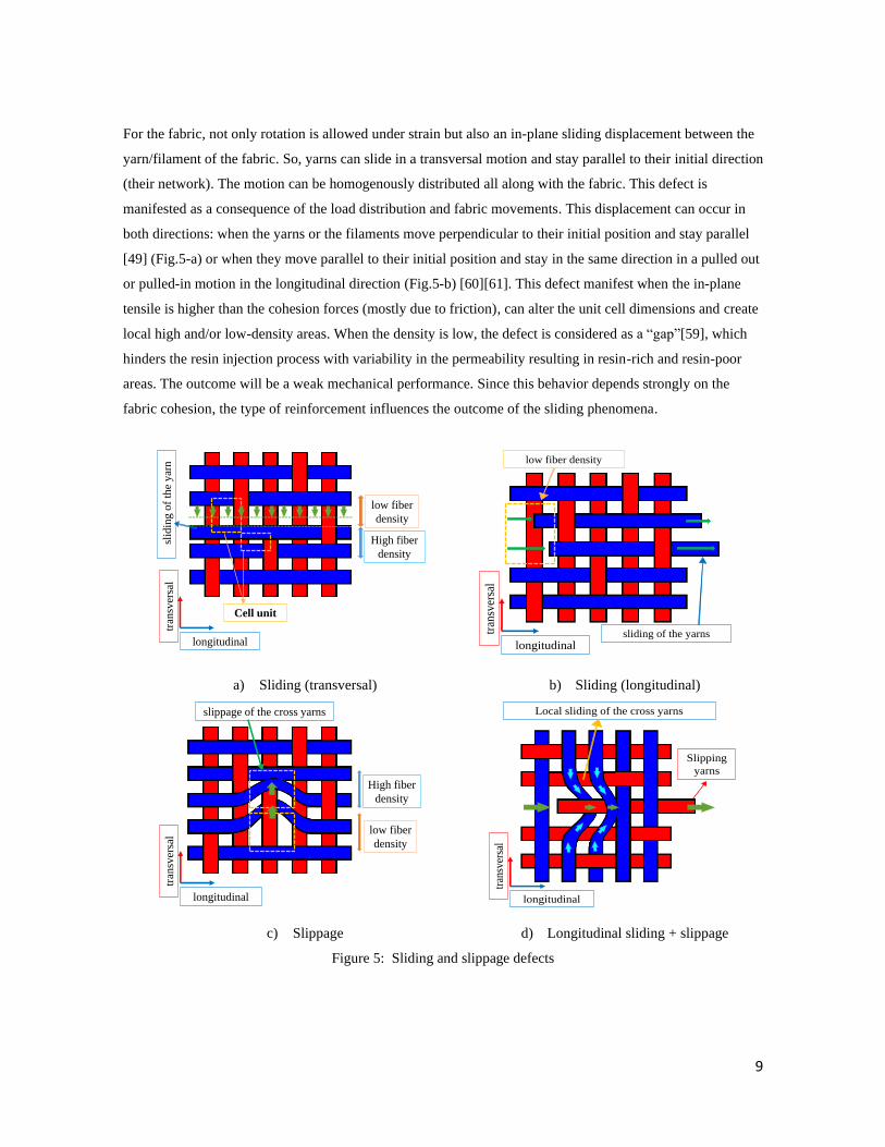
For the fabric, not only rotation is allowed under strain but also an in-plane sliding displacement between the
yarn/filament of the fabric. So, yarns can slide in a transversal motion and stay parallel to their initial direction
(their network). The motion can be homogenously distributed all along with the fabric. This defect is
manifested as a consequence of the load distribution and fabric movements. This displacement can occur in
both directions: when the yarns or the filaments move perpendicular to their initial position and stay parallel
[49] (Fig.5-a) or when they move parallel to their initial position and stay in the same direction in a pulled out
or pulled-in motion in the longitudinal direction (Fig.5-b) [60][61]. This defect manifest when the in-plane
tensile is higher than the cohesion forces (mostly due to friction), can alter the unit cell dimensions and create
local high and/or low-density areas. When the density is low, the defect is considered as a “gap”[59], which
hinders the resin injection process with variability in the permeability resulting in resin-rich and resin-poor
areas. The outcome will be a weak mechanical performance. Since this behavior depends strongly on the
fabric cohesion, the type of reinforcement influences the outcome of the sliding phenomena.
a) Sliding (transversal) b) Sliding (longitudinal)
c) Slippage d) Longitudinal sliding + slippage
Figure 5: Sliding and slippage defects
High fiber
density
low fiber
density
Cell unit
slid
ing
of
the
yar
n
longitudinal
tran
sver
sal
low fiber density
sliding of the yarns longitudinal
tran
sver
sal
High fiber
density
low fiber
density
slippage of the cross yarns
longitudinal
tran
sver
sal
Local sliding of the cross yarns
Slipping
yarns
longitudinal
tran
sver
sal
10
Thereby, these defects are most likely to occur with the unidirectional or NCF [48] or the unbalanced fabric
[39][62] where the friction and cohesion are not equally distributed in all directions or asymmetrical. This
defect has been called both “ sliding “or “slippage” or both and also called “fabric shifting” [8]. For this
particular defect the direction of the yarn or filament movement can be transversal or longitudinal, but what is
in common is that this “sliding” affects the latter in a homogeneous way all along with the fabric.
The previous defect can be created locally when the linear form of the yarns is lost and a particular zone slips
from its previous direction in a transversal direction forming an in-plane local curve (Fig.5-c). The causes are
numerous such as compression, bending or tensile that can be generated due to a local detail of the preform
that forces the fabric to take a curved shape (as an example: a hemisphere's curve [37], prim top [53] or
tetrahedral side corner [54]) and force the fabric to slip to accommodate the change in the length. It can also
be caused by the fabric maintaining system used during the pre-form process like blank holders, clips and
springs [2] or by an error in the fabric handling before the preforming process. One of the major reasons
behind creating this defect is the “sliding “, which is described previously. When yarns slide in the
longitudinal direction, the effort applied to them is higher than resistance forces, due to the reinforcement
cohesion, that they encounter which are located at the intersections with the yarns of the other network. If
these resistance forces are locally higher than the other region of the fabric, the concerned transverse yarns are
carried along locally, so they slip creating an in-plane curve (Fig.5-d), thus creating a local “slippage” [65].
This causes a drop in the local fiber density, so low that it is considered a “gap”. This defect has been also
called in the literature by “laddering” [8] and “weave pattern heterogeneity” [45].
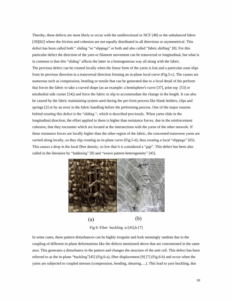
Fig 6: Fiber buckling :a-[45],b-[7]
In some cases, these pattern disturbances can be highly irregular and look seemingly random due to the
coupling of different in-plane deformations like the defects mentioned above that are concentrated in the same
area. This generates a disturbance in the pattern and changes the structure of the unit cell. This defect has been
referred to as the in-plane “buckling”[45] (Fig.6-a), fiber displacement [9] [7] (Fig.6-b) and occur when the
yarns are subjected to coupled stresses (compression, bending, shearing, ...). This lead to yarn buckling, due
11
compression force, which is very heterogeneous because of the local heterogeneity of the comression stresses.
In parallel, the tangential force, that are higer than the fabric cohesion forces, lead to slippage that affects a
group of unit cells leading the fabric architecture to lose its uniformity. These coupled forces can be generated
by severe details punch geometry that requires the fabric to sustain a combination of modes of deformation.
The profile of this defect depends on the characteristic of the material, and the distribution of the forces
behind the deformation mechanism, amplitude, curves directions…. Later, their moving direction is dictated
by the stress distribution and the process parameters consisting of the blank holder pressure, tool/fabric
friction and geometry.
2) Multi-layer preforms defects:
The out-of-plane deformation for the multi-layer configuration is like the single layer in terms of the
mechanical phenomena with additional variables, which are the layers stacking, number and thickness...
a) Out of plane deformation:
One of the most basic, yet critical, types of forming is bending the structure to a predefined angle.
Due to the radius change of the different layers of the stacking that is funcition of the value of the bending
radius of the punch, the radius area is considered a critical area with high defect risk that must therefore be
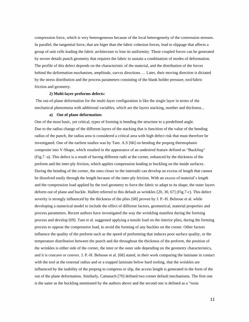
investigated. One of the earliest studies was by Tam. A.S [66] on bending the prepreg thermoplastic
composite into V-Shape, which resulted in the appearance of an undesired feature defined as “Buckling“
(Fig.7 -a). This defect is a result of having different radii at the corner, enhanced by the thickness of the
preform and the inter-ply friction, which applies compression leading to buckling on the inside surfaces.
During the bending of the corner, the ones closer to the interradii can develop an excess of length that cannot
be dissolved easily through the length because of the inter-ply friction. With an excess of material’s length
and the compression load applied by the tool geometry to force the fabric to adapt to its shape, the outer layers
deform out of plane and buckle. Hallett referred to this default as wrinkles [20, 30, 67] (Fig.7-c). This defect
severity is strongly influenced by the thickness of the plies [68] proven by J. P.-H. Belnoue et al. while
developing a numerical model to include the effect of different factors, geometrical, material properties and
process parameters. Recent authors have investigated the way the wrinkling manifest during the forming
process and develop [69]. Tam et al. suggested applying a tensile load on the interior plies, during the forming
process to oppose the compressive load, to avoid the forming of any buckles on the corner. Other factors
influence the quality of the preform such as the speed of preforming that induces poor surface quality, or the
temperature distribution between the punch and die throughout the thickness of the preform, the position of
the wrinkles is either side of the corner, the inter or the outer side depending on the geometry characteristics,
and it is concave or convex. J. P.-H. Belnoue et al. [68] stated, in their work comparing the laminate in contact
with the tool at the external radius and or a trapped laminate below hard tooling, that the wrinkles are
influenced by the inability of the prepreg to compress or slip, the access length is generated in the form of the
out of the plane deformation. Similarly, Cattanach [70] defined two corner default mechanisms. The first one
is the same as the buckling mentioned by the authors above and the second one is defined as a “resin
12
squaeezing”. This last consists of a resin-rich area at the outer corner (Fig.7-b) that appears when the external
ply surface is subjected to tensile load forcing the fabric layers to squeeze in the interior section on a smaller
radius and the resin to get out. The resin squeezing and the buckling default can also be a result of an attempt
to reduce the buckling on the inter corner by applying a tensile load on it as suggested by Tam. This
phenomenon was also investigated by L. Jerpdal [71].
Figure 7 : a- Buckling [66] , b- Resin squeezing [70], c- Thickness variation [75]
Another defect has been investigated which is the thickness reduction and volume fraction variation on the
corner that influence dramatically the uniformity of the geometrical and mechanical properties of the
structure. Hubert et al. [72] determined that the thickening of a corner tend to occur with a concave tool
contrary to the convex shape that induces the thining explained by two different mechanisms in their later
work [73]. The first being the corner/flange pressure variation, where the resin accumulates and flows to the
corner due to its locally low pressure[74] and the second being the inter-ply friction. Hallander et al. [75]
determined the influence of the interlayer friction by changing the fiber orientation and implanting a veil on
the outcome of the forming procedure of the unidirectional (UD) laminate composite with mixed ply materials
formed into the C-channel. The thickness variation at the corner with and without an interlayer veil, showed
the importance of reducing the friction between the layers at the corner, similar to that described by Bickerton
[76] (Fig.7-c) who worked on the dry fabric (woven carbon fiber and a stitched fiberglass). Bickerton found
that the thickness is at its minimum at the corner tip, reducing the space between the fabric tows and forming
an obstacle in the face of the resin flow, thus, affecting the local permeability, which is studied S. Pierce [77]
in their work where they determined the effects of the variation of the reinforcement shearing on the
permeability while building a numerical model to predict the resin flow behavior.
Besides the defect appearing on the corner, Hallander et al. investigated in their later work [57] the influence
of compression on the out-of-plane defect for the UD prepreg multi-layer forming, resulting in the fact that
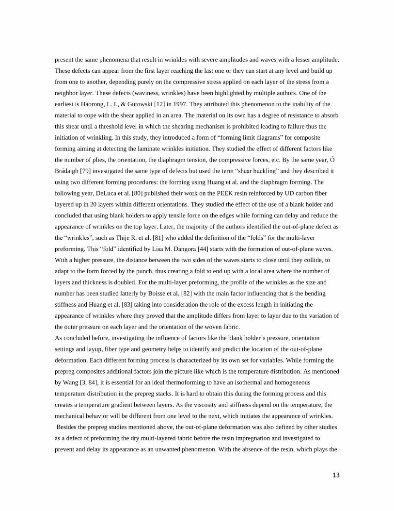
these defects can reduce the strength up to 40% [78]. They have defined two out-of-plane defects: ”Waviness”
(Fig.8-a) and “wrinkles” (Fig.8-b). These defects are due to the loss of fiber linearity (in-plane), due to the
compressive loads, giving it an amplitude in the out-of-plane direction. Both the waviness and wrinkles
13
present the same phenomena that result in wrinkles with severe amplitudes and waves with a lesser amplitude.
These defects can appear from the first layer reaching the last one or they can start at any level and build up
from one to another, depending purely on the compressive stress applied on each layer of the stress from a
neighbor layer. These defects (waviness, wrinkles) have been highlighted by multiple authors. One of the
earliest is Haorong, L. I., & Gutowski [12] in 1997. They attributed this phenomenon to the inability of the
material to cope with the shear applied in an area. The material on its own has a degree of resistance to absorb
this shear until a threshold level in which the shearing mechanism is prohibited leading to failure thus the
initiation of wrinkling. In this study, they introduced a form of “forming limit diagrams” for composite
forming aiming at detecting the laminate wrinkles initiation. They studied the effect of different factors like
the number of plies, the orientation, the diaphragm tension, the compressive forces, etc. By the same year, Ó
Brádaigh [79] investigated the same type of defects but used the term “shear buckling” and they described it
using two different forming procedures: the forming using Huang et al. and the diaphragm forming. The
following year, DeLuca et al. [80] published their work on the PEEK resin reinforced by UD carbon fiber
layered up in 20 layers within different orientations. They studied the effect of the use of a blank holder and
concluded that using blank holders to apply tensile force on the edges while forming can delay and reduce the
appearance of wrinkles on the top layer. Later, the majority of the authors identified the out-of-plane defect as
the “wrinkles”, such as Thije R. et al. [81] who added the definition of the “folds” for the multi-layer
preforming. This “fold” identified by Lisa M. Dangora [44] starts with the formation of out-of-plane waves.
With a higher pressure, the distance between the two sides of the waves starts to close until they collide, to
adapt to the form forced by the punch, thus creating a fold to end up with a local area where the number of
layers and thickness is doubled. For the multi-layer preforming, the profile of the wrinkles as the size and
number has been studied latterly by Boisse et al. [82] with the main factor influencing that is the bending
stiffness and Huang et al. [83] taking into consideration the role of the excess length in initiating the
appearance of wrinkles where they proved that the amplitude differs from layer to layer due to the variation of
the outer pressure on each layer and the orientation of the woven fabric.
As concluded before, investigating the influence of factors like the blank holder’s pressure, orientation
settings and layup, fiber type and geometry helps to identify and predict the location of the out-of-plane
deformation. Each different forming process is characterized by its own set for variables. While forming the
prepreg composites additional factors join the picture like which is the temperature distribution. As mentioned
by Wang [3, 84], it is essential for an ideal thermoforming to have an isothermal and homogeneous
temperature distribution in the prepreg stacks. It is hard to obtain this during the forming process and this
creates a temperature gradient between layers. As the viscosity and stiffness depend on the temperature, the
mechanical behavior will be different from one level to the next, which initiates the appearance of wrinkles.
Besides the prepreg studies mentioned above, the out-of-plane deformation was also defined by other studies
as a defect of preforming the dry multi-layered fabric before the resin impregnation and investigated to
prevent and delay its appearance as an unwanted phenomenon. With the absence of the resin, which plays the
14
role of a lubricant, as mentioned previously, the inter-ply friction is more severe in terms of its role in
initiating the out-of-plane deformation. That is why wrinkles are more likely to form in multi-ply settings.
Lately, Allaoui et al [5][85] investigated experimentally the effects of the fabric/fabric friction on the
initiation and the appearance of the defects with multi-layer stacked in a different orientation formed with
prism. The choice of geometry was dictated to generate the defects using its highly curved and deep draw
shape. Comparing the single layer to the multi-layer setup, the defects on the multi-layered set have a higher
magnitude and severity than the single layer. The “wrinkles” here are defined as the out-of-plane deformation
that accumulated on all layers. It is then concluded that the blank holders have great effects on inducing or
reducing the defects depending on the whole set configuration and it is stated that the orientation of the fabric
as a reference to the punch also influences the number and type of defects while working with highly curved
shapes. When ply subjects to more defects are placed in the internal position of the stacking, the compaction
of the upper ply tends to reduce the defect and prevent its expansion. Moreover, it has been shown that the
inter-layer slippage, when it's greater than the unit cell length, has more influence on the increase of the
amount and amplitude of the defects than the value of the fabric/fabric friction.
Figure 8: Out of plane deformation a- waviness b- wrinkles [78]
So the appearance and the profile of the out of planes defects are highly influenced by the deformation mode
and the stress distribution throughout the plies. Therefore, the occurrence of defects when using blank-
holders, which apply in plane tension to the fabric throught the applied pressure, differs from the case of
diaphragm forming that brings a normal uniform pressure applies on the either or both surfaces of the
laminate. With the absence of the in-plane stress to absorb, the undulations transform into wrinkles[86] and
15
the yars’ in-plane movements and rotations are very limited. This process also comes with a common defect
of the bridging due to the low pressure that goes from 0 to 1 Bar [51].
Therefore, some authors developed the concept of preform optimization to delay as much as possible the
appearance of the defects or minimize their magnitude. A. Shanwan [87] classified the different preform
parameters such as the blank holder pressure and geometry, controlling the fabric /fabric friction by inserting
a mat fabric in between and reaching an optimized preforming process by combining multiple solutions. Also,
Hao et al. [11], L.S.Liu [88] and H.Shen [89] worked on different geometries (hemisphere, box …) to
determine the influence of the tufting and the density of the stitching on the initiation of the out-of-plane
deformation of the multi-layered preforms. Since this defect depends highly on the bending stiffness
reinforcing the layers by the stitching leads the wrinkles to turn thinner each time the density of the tufting
increases. Molnàr [10] went further to develop a specific stitching path depending on the geometry. One of
the original methods to reduce the appearance of out-of-plane deformations was developed by Nosrat et al.
[9]. They separated the different layers of plain woven carbon fabric using metal sheets and implanted
segments with piezo-electric actuators to reduce the friction that translates into a strain applied on the fabric,
which may initiate the appearance of the wrinkle during the forming. They found that by using this technique
they eliminated the appearance of wrinkles even the ones that had high magnitude.
b) In-plane deformation:
The in-plane defects of the single-layer can look similar to the defects on a multilayer set but the mechanisms
behind them can vary, so with that, the classification of the 3 types of in-plane defaults put by Hallander [57]
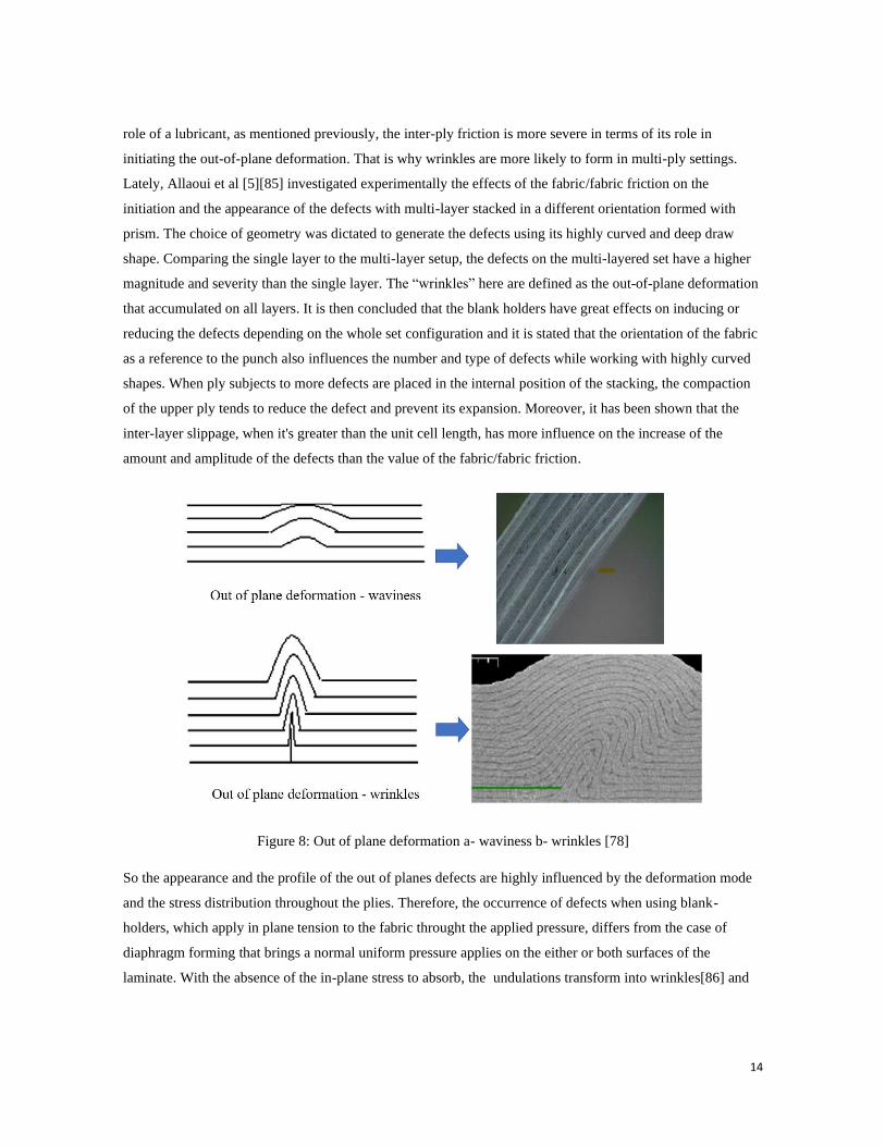
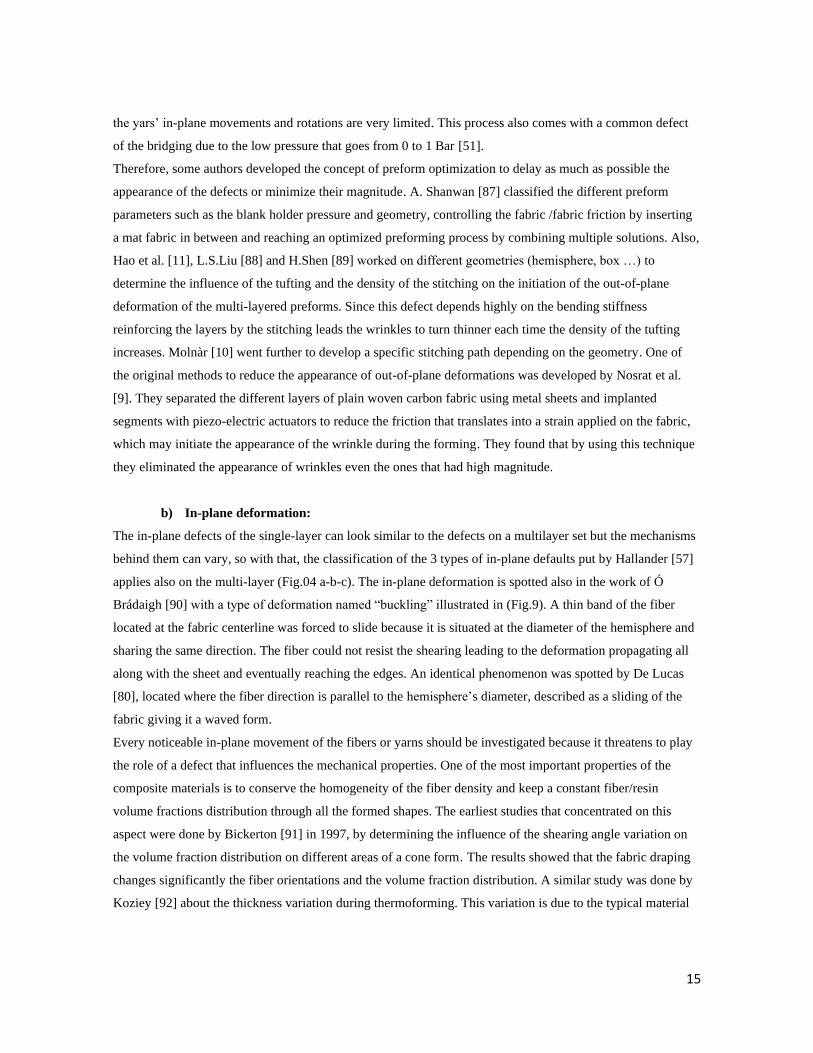
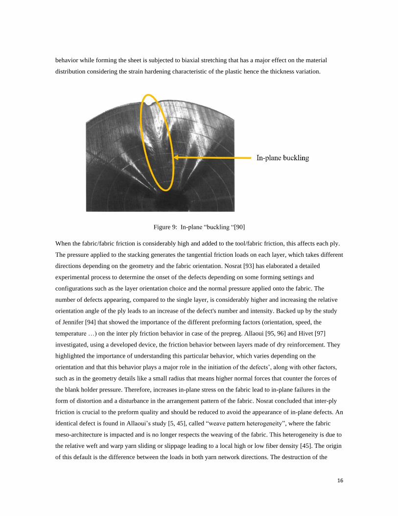
applies also on the multi-layer (Fig.04 a-b-c). The in-plane deformation is spotted also in the work of Ó
Brádaigh [90] with a type of deformation named “buckling” illustrated in (Fig.9). A thin band of the fiber
located at the fabric centerline was forced to slide because it is situated at the diameter of the hemisphere and
sharing the same direction. The fiber could not resist the shearing leading to the deformation propagating all
along with the sheet and eventually reaching the edges. An identical phenomenon was spotted by De Lucas
[80], located where the fiber direction is parallel to the hemisphere’s diameter, described as a sliding of the
fabric giving it a waved form.
Every noticeable in-plane movement of the fibers or yarns should be investigated because it threatens to play
the role of a defect that influences the mechanical properties. One of the most important properties of the
composite materials is to conserve the homogeneity of the fiber density and keep a constant fiber/resin
volume fractions distribution through all the formed shapes. The earliest studies that concentrated on this
aspect were done by Bickerton [91] in 1997, by determining the influence of the shearing angle variation on
the volume fraction distribution on different areas of a cone form. The results showed that the fabric draping
changes significantly the fiber orientations and the volume fraction distribution. A similar study was done by
Koziey [92] about the thickness variation during thermoforming. This variation is due to the typical material
16
behavior while forming the sheet is subjected to biaxial stretching that has a major effect on the material
distribution considering the strain hardening characteristic of the plastic hence the thickness variation.
Figure 9: In-plane “buckling “[90]
When the fabric/fabric friction is considerably high and added to the tool/fabric friction, this affects each ply.
The pressure applied to the stacking generates the tangential friction loads on each layer, which takes different
directions depending on the geometry and the fabric orientation. Nosrat [93] has elaborated a detailed
experimental process to determine the onset of the defects depending on some forming settings and
configurations such as the layer orientation choice and the normal pressure applied onto the fabric. The
number of defects appearing, compared to the single layer, is considerably higher and increasing the relative
orientation angle of the ply leads to an increase of the defect's number and intensity. Backed up by the study
of Jennifer [94] that showed the importance of the different preforming factors (orientation, speed, the
temperature …) on the inter ply friction behavior in case of the prepreg. Allaoui [95, 96] and Hivet [97]
investigated, using a developed device, the friction behavior between layers made of dry reinforcement. They
highlighted the importance of understanding this particular behavior, which varies depending on the
orientation and that this behavior plays a major role in the initiation of the defects’, along with other factors,
such as in the geometry details like a small radius that means higher normal forces that counter the forces of
the blank holder pressure. Therefore, increases in-plane stress on the fabric lead to in-plane failures in the
form of distortion and a disturbance in the arrangement pattern of the fabric. Nosrat concluded that inter-ply
friction is crucial to the preform quality and should be reduced to avoid the appearance of in-plane defects. An
identical defect is found in Allaoui’s study [5, 45], called “weave pattern heterogeneity”, where the fabric
meso-architecture is impacted and is no longer respects the weaving of the fabric. This heterogeneity is due to
the relative weft and warp yarn sliding or slippage leading to a local high or low fiber density [45]. The origin
of this default is the difference between the loads in both yarn network directions. The destruction of the
17
pattern structure occurs when the frictional tangential forces, generated by the blank holders on one of the
yarn directions are higher than the fabric cohesion. This sliding depends strongly on the complexity of that
shape generates severe stress due to the in-plane load distribution.
2. Yarn defects:
The preforming process affects the structure of the fabric at the macroscopic level and it inevitably goes into
the micro and mesoscopic levels that affect the yarns or fiber filaments.
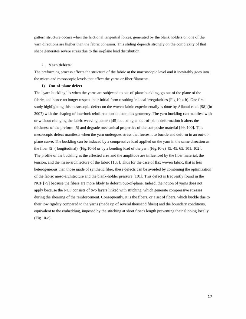
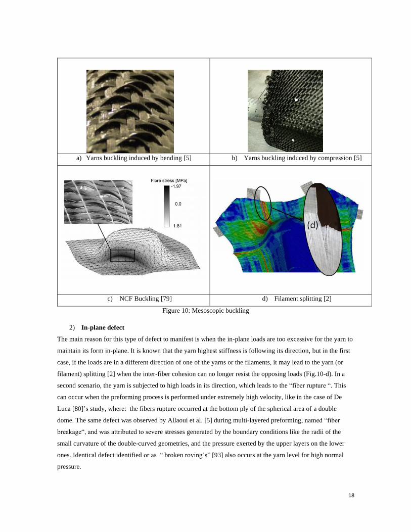
1) Out-of-plane defect
The “yarn buckling” is when the yarns are subjected to out-of-plane buckling, go out of the plane of the
fabric, and hence no longer respect their initial form resulting in local irregularities (Fig.10-a-b). One first
study highlighting this mesoscopic defect on the woven fabric experimentally is done by Allaoui et al. [98] (in
2007) with the shaping of interlock reinforcement on complex geometry. The yarn buckling can manifest with
or without changing the fabric weaving pattern [45] but being an out-of-plane deformation it alters the
thickness of the preform [5] and degrade mechanical properties of the composite material [99, 100]. This
mesoscopic defect manifests when the yarn undergoes stress that forces it to buckle and deform in an out-of-
plane curve. The buckling can be induced by a compressive load applied on the yarn in the same direction as
the fiber [5] ( longitudinal) (Fig.10-b) or by a bending load of the yarn (Fig.10-a) [5, 45, 65, 101, 102].
The profile of the buckling as the affected area and the amplitude are influenced by the fiber material, the
tension, and the meso-architecture of the fabric [103]. Thus for the case of flax woven fabric, that is less
heterogeneous than those made of synthetic fiber, these defects can be avoided by combining the optimization
of the fabric meso-architecture and the blank-holder pressure [101]. This defect is frequently found in the
NCF [79] because the fibers are more likely to deform out-of-plane. Indeed, the notion of yarns does not
apply because the NCF consists of two layers linked with stitching, which generate compressive stresses
during the shearing of the reinforcement. Consequently, it is the fibers, or a set of fibers, which buckle due to
their low rigidity compared to the yarns (made up of several thousand fibers) and the boundary conditions,
equivalent to the embedding, imposed by the stitching at short fiber's length preventing their slipping locally
(Fig.10-c).
18
a) Yarns buckling induced by bending [5] b) Yarns buckling induced by compression [5]
c) NCF Buckling [79] d) Filament splitting [2]
Figure 10: Mesoscopic buckling
2) In-plane defect
The main reason for this type of defect to manifest is when the in-plane loads are too excessive for the yarn to
maintain its form in-plane. It is known that the yarn highest stiffness is following its direction, but in the first
case, if the loads are in a different direction of one of the yarns or the filaments, it may lead to the yarn (or
filament) splitting [2] when the inter-fiber cohesion can no longer resist the opposing loads (Fig.10-d). In a
second scenario, the yarn is subjected to high loads in its direction, which leads to the “fiber rupture “. This
can occur when the preforming process is performed under extremely high velocity, like in the case of De
Luca [80]’s study, where: the fibers rupture occurred at the bottom ply of the spherical area of a double
dome. The same defect was observed by Allaoui et al. [5] during multi-layered preforming, named “fiber
breakage“, and was attributed to severe stresses generated by the boundary conditions like the radii of the
small curvature of the double-curved geometries, and the pressure exerted by the upper layers on the lower
ones. Identical defect identified or as “ broken roving’s” [93] also occurs at the yarn level for high normal
pressure.
19
III. Discussions
To better understand the defects of the composite preforming, it is important to unify the understanding of
each defect's description and on which scale it occurs. Table 1 to 3 is our attempt to summarize most defects
found in the literature, which are classified according to the scale on where they appear: the multi-layer,
monolayer and yarn defects. For each scale, defects manifest out-of-plane or in-plane. The description
provided is an assembly of their common description gived by the authors distinguishing the different
vocabulary used to describe the same type of defect. We can conclude from it that the vocabulary referring to
composite preforming defects is not yet standardized. This variety in the vocabulary used can be because the
authors’ use different types of reinforcement (NCF, woven, interlock, unidirectional…), or since some of
these defects can be similar but caused by different factors or conditions (buckling, slippage, etc.) or for the
fact that the same cause can generate different defects. Ideally, to be able to describe a defect it should be in a
reference to the behavior mechanisms and the mode of deformation that caused it to appear. This is not simple
to apply since the stress/deformation is under the influence of other parameters such as the details of the
preform geometry, the boundary conditions, the fabric structure, the fabric behavior, etc. Then, the fact that
the reinforcement is highly heterogeneous, so we have the defects that appear locally and the ones that affect
the whole length of the reinforcement. This highlights if defects should be named the same under different
scales.
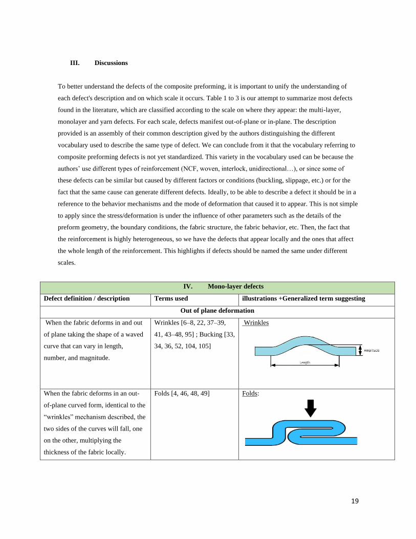
IV. Mono-layer defects
Defect definition / description Terms used illustrations +Generalized term suggesting
Out of plane deformation
When the fabric deforms in and out
of plane taking the shape of a waved
curve that can vary in length,
number, and magnitude.
Wrinkles [6–8, 22, 37–39,
41, 43–48, 95] ; Bucking [33,
34, 36, 52, 104, 105]
Wrinkles
When the fabric deforms in an out-
of-plane curved form, identical to the
“wrinkles” mechanism described, the
two sides of the curves will fall, one
on the other, multiplying the
thickness of the fabric locally.
Folds [4, 46, 48, 49] Folds:
20
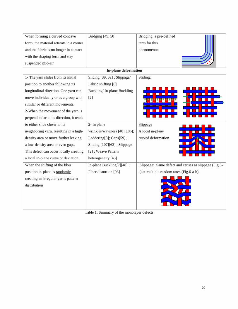
When forming a curved concave
form, the material retreats in a corner
and the fabric is no longer in contact
with the shaping form and stay
suspended mid-air
Bridging [49, 50] Bridging: a pre-defined
term for this
phenomenon
In-plane deformation
1- The yarn slides from its initial
position to another following its
longitudinal direction. One yarn can
move individually or as a group with
similar or different movements.
2-When the movement of the yarn is
perpendicular to its direction, it tends
to either slide closer to its
neighboring yarn, resulting in a high-
density area or move further leaving
a low-density area or even gaps.
This defect can occur locally creating
a local in-plane curve or deviation.
Sliding [39, 62] ; Slippage/
Fabric shifting [8]
Buckling/ In-plane Buckling
[2]
Sliding:
2- In plane
wrinkles/waviness [48][106];
Laddering[8]; Gaps[59] ;
Sliding [107][63] ; Slippage
[2] ; Weave Pattern
heterogeneity [45]
Slippage
A local in-plane
curved deformation
When the shifting of the fiber
position in-plane is randomly
creating an irregular yarns pattern
distribution
In-plane Buckling[7][48] ;
Fiber distortion [93]
Slippage: Same defect and causes as slippage (Fig.5-
c) at multiple random rates (Fig.6-a-b).
Table 1: Summary of the monolayer defects
21
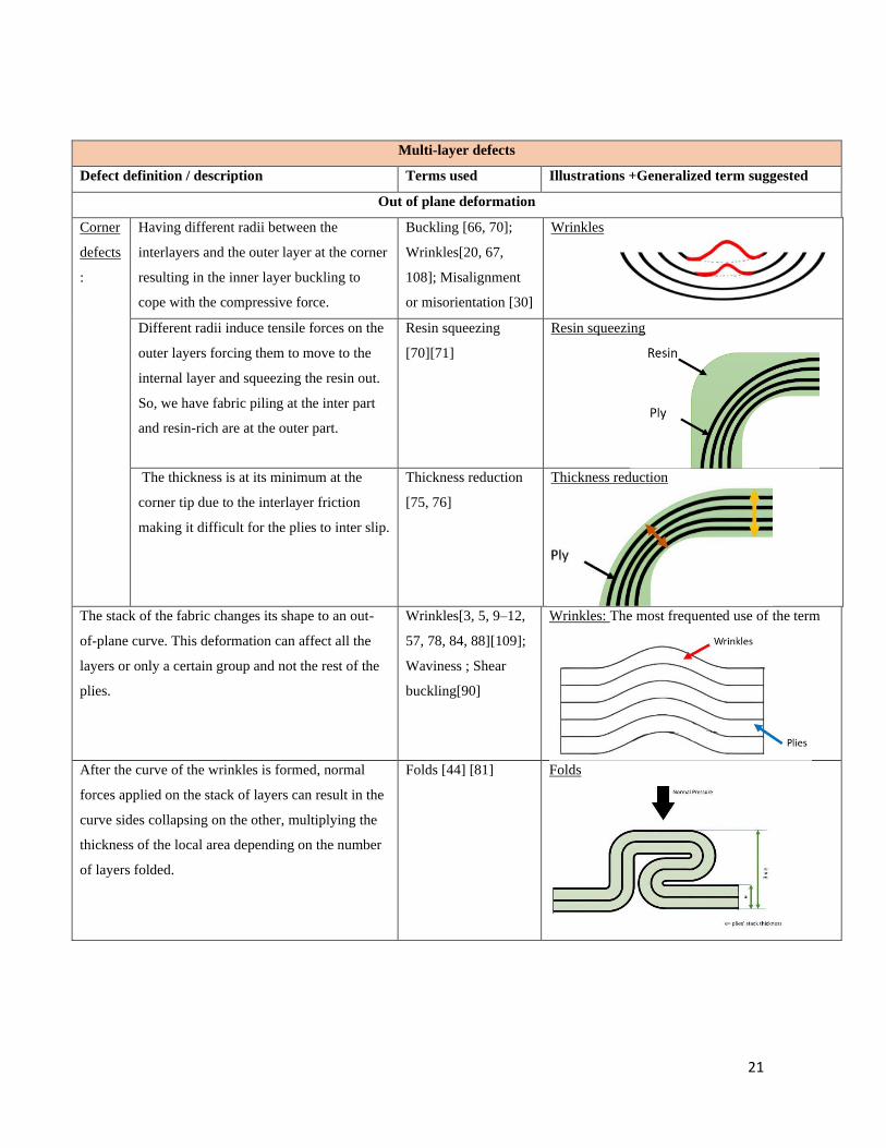
Multi-layer defects
Defect definition / description Terms used Illustrations +Generalized term suggested
Out of plane deformation
Corner
defects
:
Having different radii between the
interlayers and the outer layer at the corner
resulting in the inner layer buckling to
cope with the compressive force.
Buckling [66, 70];
Wrinkles[20, 67,
108]; Misalignment
or misorientation [30]
Wrinkles
Different radii induce tensile forces on the
outer layers forcing them to move to the
internal layer and squeezing the resin out.
So, we have fabric piling at the inter part
and resin-rich are at the outer part.
Resin squeezing
[70][71]
Resin squeezing
The thickness is at its minimum at the
corner tip due to the interlayer friction
making it difficult for the plies to inter slip.
Thickness reduction
[75, 76]
Thickness reduction
The stack of the fabric changes its shape to an out-
of-plane curve. This deformation can affect all the
layers or only a certain group and not the rest of the
plies.
Wrinkles[3, 5, 9–12,
57, 78, 84, 88][109];
Waviness ; Shear
buckling[90]
Wrinkles: The most frequented use of the term
After the curve of the wrinkles is formed, normal
forces applied on the stack of layers can result in the
curve sides collapsing on the other, multiplying the
thickness of the local area depending on the number
of layers folded.
Folds [44] [81] Folds
22
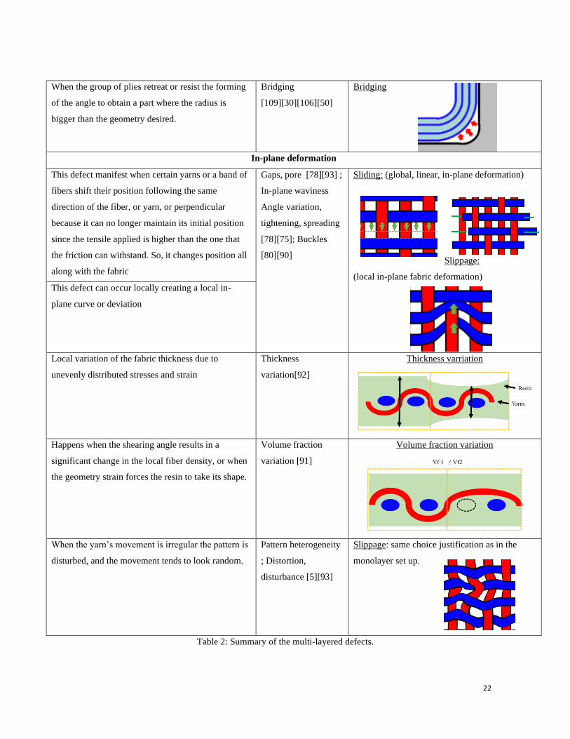
Table 2: Summary of the multi-layered defects.
When the group of plies retreat or resist the forming
of the angle to obtain a part where the radius is
bigger than the geometry desired.
Bridging
[109][30][106][50]
Bridging
In-plane deformation
This defect manifest when certain yarns or a band of
fibers shift their position following the same
direction of the fiber, or yarn, or perpendicular
because it can no longer maintain its initial position
since the tensile applied is higher than the one that
the friction can withstand. So, it changes position all
along with the fabric
Gaps, pore [78][93] ;
In-plane waviness
Angle variation,
tightening, spreading
[78][75]; Buckles
[80][90]
Sliding: (global, linear, in-plane deformation)
Slippage:
(local in-plane fabric deformation)
This defect can occur locally creating a local in-
plane curve or deviation
Local variation of the fabric thickness due to
unevenly distributed stresses and strain
Thickness
variation[92]
Thickness varriation
Happens when the shearing angle results in a
significant change in the local fiber density, or when
the geometry strain forces the resin to take its shape.
Volume fraction
variation [91]
Volume fraction variation
When the yarn’s movement is irregular the pattern is
disturbed, and the movement tends to look random.
Pattern heterogeneity
; Distortion,
disturbance [5][93]
Slippage: same choice justification as in the
monolayer set up.
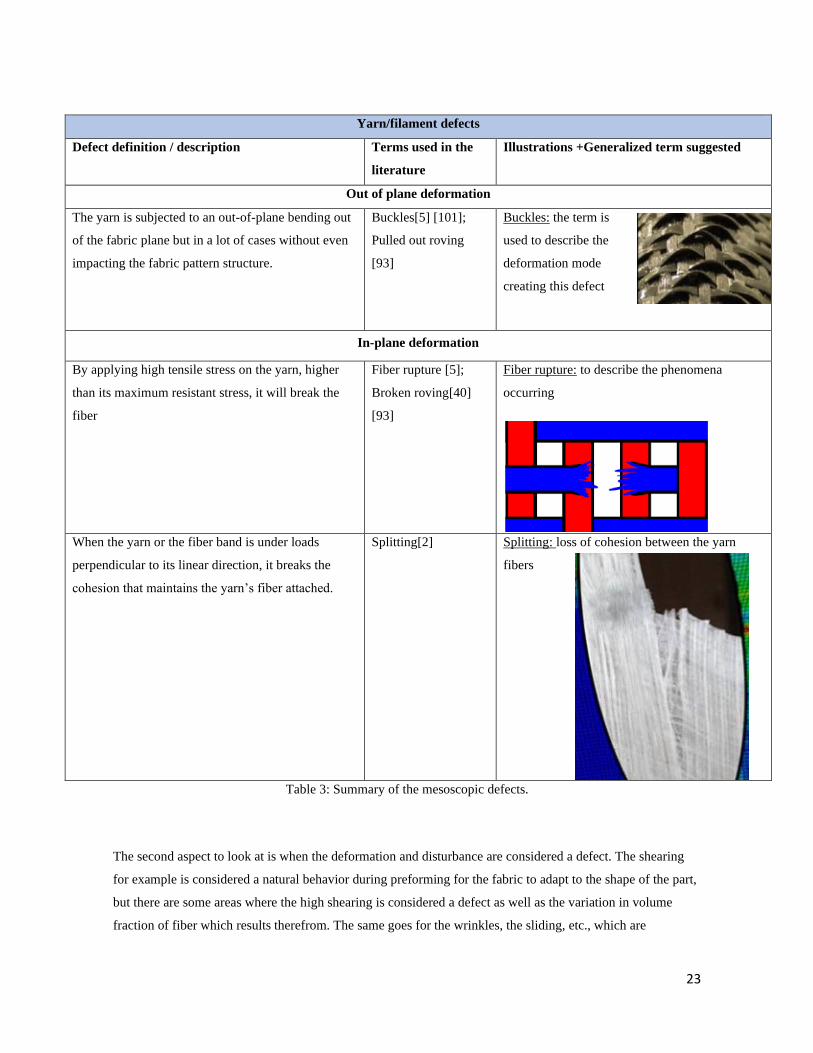
23
Yarn/filament defects
Defect definition / description Terms used in the
literature
Illustrations +Generalized term suggested
Out of plane deformation
The yarn is subjected to an out-of-plane bending out
of the fabric plane but in a lot of cases without even
impacting the fabric pattern structure.
Buckles[5] [101];
Pulled out roving
[93]
Buckles: the term is
used to describe the
deformation mode
creating this defect
In-plane deformation
By applying high tensile stress on the yarn, higher
than its maximum resistant stress, it will break the
fiber
Fiber rupture [5];
Broken roving[40]
[93]
Fiber rupture: to describe the phenomena
occurring
When the yarn or the fiber band is under loads
perpendicular to its linear direction, it breaks the
cohesion that maintains the yarn’s fiber attached.
Splitting[2] Splitting: loss of cohesion between the yarn
fibers
Table 3: Summary of the mesoscopic defects.
The second aspect to look at is when the deformation and disturbance are considered a defect. The shearing
for example is considered a natural behavior during preforming for the fabric to adapt to the shape of the part,
but there are some areas where the high shearing is considered a defect as well as the variation in volume
fraction of fiber which results therefrom. The same goes for the wrinkles, the sliding, etc., which are
24
considered as a defects the moment that they are visible usually with the naked eye without considering a
measurable threshold.. If we consider the case of a wrinkle is a form of out-of-plane bending deformation and
thus a fabric behavior. Starting from which threshold magnitude we can consider it as a defect and not a
deformation? This magnitude should be a function of the fabric thickness but while ideally considering its
criticality on the composite mechanical behavior and its effect on the further steps of the process (resin
injection for example) where the wrinkles can disappear due to the compression during the fabrics compaction
between process tools. The same remark can be made to other defects like "sliding", "gap", "slippage", ...
where the limit to consider these phenomena as defects could be related to the fabric meso-architecture
parameters (yarn width, unit cell length, ...) and its criticality on the composite behavior.
Many studies have been concentrating on the defects located at a corner. The vocabulary used by authors like
“wrinkles”, “resin squeezing” and “thickness reduction” (Tab.2). These distinctive terms are easily identified
for being a defect of the corner.
The defects referred to as a “thickness and volume fraction variation “ are more likely to describe the outcome
of a defect since they are a way to measure the physical impact of a defect (Tab.2), where they can be the
result of many different types of defects manifesting under a different mechanism.
Noticing that the term “buckling “ has been used frequently to describe different defects in different scales
multi-layers, mono-layers and even at the yarn scale, which is understandable because “buckling” here refers
to the deformation mode that caused all these defects, either in-plane or out-of-plane, so to avoid the
confusion, our choice was to use it on the out of plane yarn buckling since the only term that has been used to
describe it.
The method that we used to identify each defect started by classifying the scale in which it occurs, then
deciding them into in-plane and out-of-plane to avoid any confusion between defects with the same name and
in different scales and than to attribute names according to defect we chose. We favored the terms that they
are frequently used, which are more assertive describing the defect to lessen the chances of a mix-up, the
defects having the same deformation outcome and causes are named the same.
V. Conclusion
Understanding the preforming defects to obtain non-defective parts, is a major issue for the extension of the
use of composites materials in several industries’ sectors. For this purpose, it is necessary to understand the
deformation mechanisms and the material's behavior in response, and master the many factors that play a role
in the initiation of defects. There is a diversity in the work done by the researches until now, a variation in
investigating these factors and proposing a solution to predict their appearance and ways to suppress them.
This diversity created a difference in the way authors have been defining and identifying these defects and
even the vocabulary of reference terms.
25
In this review, we started by identifying the defects listed in the literature and classified them according to the
scale where they appear, i.e. multi-layers, monolayer, and yarns. Each of those defects is characterized by
their type of deformation being out or in-plane. We started by identifying each defect searching for the
similarities in the way different authors' definitions and interpretations of the manifestation mechanisms and
the cause of their appearance. The cause of these defects, which are detailed for each, can be due to the
material’s behavior due to the deformation mode they undergo, the preforming setup or the geometry
characteristics we are aiming for, or the process parameter is chosen.
After studying the defects defined by authors we concluded that authors have used different ways to identify
the defects. Some of them referred to the cause of the defect and the mechanisms behind their appearance,
others referred to the type of deformation created by these mechanisms and others used terms to describe the
outcome of the deformation. So, we can find a defect with different definitions and terms while they are
describing the same defect, while in other cases different defect was referred to by the same term.
Our attempt to put together a way to unite the vocabulary used to name each defect is not the same from an
author to another, we summarised a definition that helps identify the defects and proposed a term of reference.
Having a solid definition and vocabulary will avoid any confusion in the future in the community when
working on the defects.
This can be the first contribution to converge toward a composite forming defects manual that would make it
possible to work on the same basis for the numerous studies in progress or to come which relate to several
aspects related to formatting defects such as: a more detailed understanding of the mechanisms involved
during the appearance of these defects, the evaluation of the effect induced on the performance of the
composite material as well as the establishment of criteria taking into account these two aspects and which
would be implemented in the numeriacal codes.
All of this knowledge would make it possible to increase the mastery of composites processes and therefore
their use in different industrial sctors.
Conflict of Interest:
The authors declare that they have no conflict of interest.
References
1. Paul SK (2013) Theoretical analysis of strain- and stress-based forming limit diagrams. J Strain Anal Eng Des
48:177–188. https://doi.org/10.1177/0309324712468524
2. Harrison P, Gomes R, Curado-Correia N (2013) Press forming a 0/90 cross-ply advanced thermoplastic
composite using the double-dome benchmark geometry. Compos Part A Appl Sci Manuf 54:56–69.
https://doi.org/10.1016/j.compositesa.2013.06.014
3. Wang P, Hamila N, Boisse P (2013) Thermoforming simulation of multilayer composites with continuous fibres
and thermoplastic matrix. Compos Part B Eng 52:127–136. https://doi.org/10.1016/j.compositesb.2013.03.045
26
4. Skordos AA, Monroy Aceves C, Sutcliffe MPF (2007) A simplified rate dependent model of forming and
wrinkling of pre-impregnated woven composites. Compos Part A Appl Sci Manuf 38:1318–1330.
https://doi.org/10.1016/j.compositesa.2006.11.005
5. Allaoui S, Cellard C, Hivet G (2015) Effect of inter-ply sliding on the quality of multilayer interlock dry fabric
preforms. Compos Part A Appl Sci Manuf 68:336–345. https://doi.org/10.1016/j.compositesa.2014.10.017
6. Allaoui S, Boisse P, Chatel S, et al (2011) Experimental and numerical analyses of textile reinforcement forming
of a tetrahedral shape. Compos Part A Appl Sci Manuf 42:612–622.
https://doi.org/10.1016/j.compositesa.2011.02.001
7. Lee JS, Hong SJ, Yu WR, Kang TJ (2007) The effect of blank holder force on the stamp forming behavior of
non-crimp fabric with a chain stitch. Compos Sci Technol 67:357–366.
https://doi.org/10.1016/j.compscitech.2006.09.009
8. Turk MA, Vermes B, Thompson AJ, et al (2020) Mitigating forming defects by local modification of dry
preforms Mark. Compos Part A Appl Sci Manuf 128:105643. https://doi.org/10.1016/j.compositesa.2019.105643
9. Nosrat Nezami F, Gereke T, Cherif C (2017) Active forming manipulation of composite reinforcements for the
suppression of forming defects. Compos Part A Appl Sci Manuf 99:94–101.
https://doi.org/10.1016/j.compositesa.2017.04.011
10. Molnár P, Ogale A, Lahr R, Mitschang P (2007) Influence of drapability by using stitching technology to reduce
fabric deformation and shear during thermoforming. Compos Sci Technol 67:3386–3393.
https://doi.org/10.1016/j.compscitech.2007.03.022
11. Hao S, Wang P, Legrand X, et al (2019) Influence of the tufting pattern on the formability of tufted multi-layered
preforms. Compos Struct 228:111356. https://doi.org/10.1016/j.compstruct.2019.111356
12. Haorong LI, Gutowski T (1997) Chapter 11 The forming of thermoset composites. Compos Mater Ser 11:441–
472. https://doi.org/10.1016/S0927-0108(97)80013-6
13. Viisainen J V., Hosseini A, Sutcliffe MPF (2021) Experimental investigation, using 3D digital image correlation,
into the effect of component geometry on the wrinkling behaviour and the wrinkling mechanisms of a biaxial
NCF during preforming. Compos Part A Appl Sci Manuf 142:106248.
https://doi.org/10.1016/j.compositesa.2020.106248
14. El Said B, Green S, Hallett SR (2014) Kinematic modelling of 3D woven fabric deformation for structural scale
features. Compos Part A Appl Sci Manuf 57:95–107. https://doi.org/10.1016/j.compositesa.2013.11.006
15. Tavana R, Najar SS, Abadi MT, Sedighi M (2013) Meso/macro-scale finite element model for forming process
of woven fabric reinforcements. J Compos Mater 47:2075–2085. https://doi.org/10.1177/0021998312454034
16. Sherwood JA, Fetfatsidis KA, Gorczyca JL, Berger L (2012) Fabric thermostamping in polymer matrix
composites. Woodhead Publishing Limited
17. Dörr D, Joppich T, Schirmaier F, et al (2016) A Method for Validation of Finite Element Forming Simulation On
Basis of a Pointwise Comparison of Distance and Curvature. 170011:. https://doi.org/10.1063/1.4963567
18. Dörr D, Brymerski W, Ropers S, et al (2017) A Benchmark Study of Finite Element Codes for Forming
Simulation of Thermoplastic UD-Tapes. Procedia CIRP 66:101–106. https://doi.org/10.1016/j.procir.2017.03.223
19. Boisse P, Hamila N, Vidal-sallé E, Dumont F (2011) Simulation of wrinkling during textile composite
reinforcement forming . Influence of tensile , in-plane shear and bending stiffnesses. Compos Sci Technol
71:683–692. https://doi.org/10.1016/j.compscitech.2011.01.011
27
20. Hallett SR, Belnoue JPH, Nixon-Pearson OJ, et al (2016) Understanding and prediction of fibre waviness defect
generation. Proc Am Soc Compos - 31st Tech Conf ASC 2016
21. Khan MA, Mabrouki T, Vidal-Sallé E, Boisse P (2010) Numerical and experimental analyses of woven
composite reinforcement forming using a hypoelastic behaviour. Application to the double dome benchmark. J
Mater Process Technol 210:378–388. https://doi.org/10.1016/j.jmatprotec.2009.09.027
22. Bloom LD, Wang J, Potter KD (2013) Damage progression and defect sensitivity: An experimental study of
representative wrinkles in tension. Compos Part B Eng 45:449–458.
https://doi.org/10.1016/j.compositesb.2012.05.021
23. El-Hajjar RF, Petersen DR (2011) Gaussian function characterization of unnotched tension behavior in a
carbon/epoxy composite containing localized fiber waviness. Compos Struct 93:2400–2408.
https://doi.org/10.1016/j.compstruct.2011.03.029
24. Wang J, Potter KD, Hazra K, Wisnom MR (2012) Experimental fabrication and characterization of out-of-plane
fiber waviness in continuous fiber-reinforced composites. J Compos Mater 46:2041–2053.
https://doi.org/10.1177/0021998311429877
25. Mukhopadhyay S, Jones MI, Hallett SR (2015) Tensile failure of laminates containing an embedded wrinkle;
numerical and experimental study. Compos Part A Appl Sci Manuf 77:219–228.
https://doi.org/10.1016/j.compositesa.2015.07.007
26. Xu X, Jones MI, Ali H, et al (2020) Effect of out-of-plane wrinkles in curved multi-directional carbon/epoxy
laminates. Compos Sci Technol 197:108282. https://doi.org/10.1016/j.compscitech.2020.108282
27. Xie N, Smith RA, Mukhopadhyay S, Hallett SR (2018) A numerical study on the influence of composite wrinkle
defect geometry on compressive strength. Mater Des 140:7–20. https://doi.org/10.1016/j.matdes.2017.11.034
28. Mukhopadhyay S, Nixon-Pearson OJ, Hallett SR (2018) An experimental and numerical study on fatigue damage
development in laminates containing embedded wrinkle defects. Int J Fatigue 107:1–12.
https://doi.org/10.1016/j.ijfatigue.2017.10.008
29. Nikishkov Y, Makeev A, Seon G (2013) Progressive fatigue damage simulation method for composites. Int J
Fatigue 48:266–279. https://doi.org/10.1016/j.ijfatigue.2012.11.005
30. Potter K, Khan B, Wisnom M, et al (2008) Variability, fibre waviness and misalignment in the determination of
the properties of composite materials and structures. Compos Part A Appl Sci Manuf 39:1343–1354.
https://doi.org/10.1016/j.compositesa.2008.04.016
31. Fedulov BN, Antonov FK, Safonov AA, et al (2015) Influence of fibre misalignment and voids on composite
laminate strength. J Compos Mater 49:2887–2896. https://doi.org/10.1177/0021998314557533
32. Creech G, Pickett AK (2006) Meso-modelling of Non-crimp Fabric composites for coupled drape and failure
analysis. J Mater Sci 41:6725–6736. https://doi.org/10.1007/s10853-006-0213-6
33. Tam AS, Gutowski TG (1990) The kinematics for forming ideal aligned fibre composites into complex shapes.
Compos Manuf 1:219–228. https://doi.org/10.1016/0956-7143(90)90044-W
34. Christie GR, Collins IF, Bhattacharyya D (1995) Out-of-plane buckling of fiber-reinforced thermoplastic sheets
under homogeneous biaxial conditions. J Appl Mech Trans ASME 62:834–840.
https://doi.org/10.1115/1.2896008
35. Pavan Kumar J, Uday Kumar R, Ramakrishna B, et al (2018) Formability of sheet metals - A review. IOP Conf
Ser Mater Sci Eng 455:. https://doi.org/10.1088/1757-899X/455/1/012081
28
36. Yu JZ, Cai Z, Ko FK (1994) Formability of textile preforms for composite applications. Part 1: Characterization
experiments. Compos Manuf 5:113–122. https://doi.org/10.1016/0956-7143(94)90062-0
37. Mohammed U, Lekakou C, Bader MG (2000) Experimental studies and analysis of the draping of woven fabrics.
Compos Part A Appl Sci Manuf 31:1409–1420. https://doi.org/10.1016/S1359-835X(00)00080-4
38. Boisse P, Gasser A, Hivet G (2001) Analysis of the mechanical behaviour : determination of the biaxial tensio-
strain surfaces and their use in forming simulations. Exp Mech 32:260–269
39. Zouari B, Daniel J, Boisse P (2006) A woven reinforcement forming simulation method . Influence of the shear
stiffness To cite this version : HAL Id : hal-00081069 A woven reinforcement forming simulation method .
Influence of the shear stiffness
40. Komeili M, Milani AS (2016) On effect of shear-tension coupling in forming simulation of woven fabric
reinforcements. Compos Part B Eng 99:17–29. https://doi.org/10.1016/j.compositesb.2016.05.004
41. Boisse P, Hamila N, Vidal-Sallé E, Dumont F (2011) Simulation of wrinkling during textile composite
reinforcement forming. Influence of tensile, in-plane shear and bending stiffnesses. Compos Sci Technol 71:683–
692. https://doi.org/10.1016/j.compscitech.2011.01.011
42. de Bilbao E, Soulat D, Hivet G, Gasser A (2010) Experimental Study of Bending Behaviour of Reinforcements.
Exp Mech 50:333–351. https://doi.org/10.1007/s11340-009-9234-9
43. Boisse P, Colmars J, Hamila N, et al (2018) Bending and wrinkling of composite fiber preforms and prepregs. A
review and new developments in the draping simulations. Compos Part B Eng 141:234–249.
https://doi.org/10.1016/j.compositesb.2017.12.061
44. Dangora LM, Mitchell CJ, Sherwood JA (2015) Predictive model for the detection of out-of-plane defects
formed during textile-composite manufacture. Compos Part A Appl Sci Manuf 78:102–112.
https://doi.org/10.1016/j.compositesa.2015.07.011
45. Allaoui S, Hivet G, Soulat D, et al (2014) Experimental preforming of highly double curved shapes with a case
corner using an interlock reinforcement. Int J Mater Form 7:155–165. https://doi.org/10.1007/s12289-012-1116-5
46. Long AC, Rudd CD (1994) A simulation of reinforcement deformation during the production of preforms for
liquid moulding processes. Proc Inst Mech Eng Part B J Eng Manuf 208:269–278.
https://doi.org/10.1243/PIME_PROC_1994_208_088_02
47. Wang J, Paton R, Page JR (1999) Draping of woven fabric preforms and prepregs for production of polymer
composite components. Compos Part A Appl Sci Manuf 30:757–765. https://doi.org/10.1016/S1359-
835X(98)00187-0
48. Böhler P, Härtel F, Middendorf P (2013) Identification of forming limits for unidirectional carbon textiles in
reality and mesoscopic simulationy and mesoscopic simulation. Key Eng Mater 554–557:423–432.
https://doi.org/10.4028/www.scientific.net/KEM.554-557.423
49. Middendorf P PROCESS PARAMETER STUDIES AND COMPARISON OF. 7577–7587
50. Alshahrani H, Hojjati M (2017) Experimental and numerical investigations on formability of out-of-autoclave
thermoset prepreg using a double diaphragm process. Compos Part A Appl Sci Manuf 101:199–214.
https://doi.org/10.1016/j.compositesa.2017.06.021
51. Chen S, McGregor OPL, Endruweit A, et al (2017) Double diaphragm forming simulation for complex
composite structures. Compos Part A Appl Sci Manuf 95:346–358.
https://doi.org/10.1016/j.compositesa.2017.01.017
29
52. ÓBrádaigh CM, McGuinness GB, Pipes RB (1993) Numerical analysis of stresses and deformations in composite
materials sheet forming: central indentation of a circular sheet. Compos Manuf 4:67–83.
https://doi.org/10.1016/0956-7143(93)90074-I
53. Fetfatsidis KA, Jauffrès D, Sherwood JA, Chen J (2013) Characterization of the tool/fabric and fabric/fabric
friction for woven-fabric composites during the thermostamping process. Int J Mater Form 6:209–221.
https://doi.org/10.1007/s12289-011-1072-5
54. Harrison P, ten Thije R, Akkerman R, Long AC (2010) Characterisation and modelling friction at the tool-ply
interface for thermoplastic woven composites. 1–2
55. ten Thije RHW, Akkerman R, van der Meer L, Ubbink MP (2008) Tool-ply friction in thermoplastic composite
forming. Int J Mater Form 1:953–956. https://doi.org/10.1007/s12289-008-0215-9
56. Laroche D V-KT (1993) Forming of Woven Fabric Composites. 1825–1839
57. Hallander P, Akermo M, Mattei C, et al (2013) An experimental study of mechanisms behind wrinkle
development during forming of composite laminates. Compos Part A Appl Sci Manuf 50:54–64.
https://doi.org/10.1016/j.compositesa.2013.03.013
58. Thor M, Sause MGR, Hinterhölzl RM (2020) Mechanisms of Origin and Classification of Out-of-Plane Fiber
Waviness in Composite Materials—A Review. J Compos Sci 4:130. https://doi.org/10.3390/jcs4030130
59. Li L, Zhao Y, Zhao X, et al (2015) The effect of preforming quality on the permeability of non-crimp fabrics and
the mechanical properties of their composites. ICCM Int Conf Compos Mater 2015-July:19–24
60. Bel S, Boisse P, Dumont F (2012) Analyses of the deformation mechanisms of non-crimp fabric composite
reinforcements during preforming. Appl Compos Mater 19:513–528. https://doi.org/10.1007/s10443-011-9207-x
61. Bel S, Hamila N, Boisse P, Dumont F (2012) Finite element model for NCF composite reinforcement
preforming: Importance of inter-ply sliding. Compos Part A Appl Sci Manuf 43:2269–2277.
https://doi.org/10.1016/j.compositesa.2012.08.005
62. Daniel J-L, Soulat D, Dumont F, et al (2003) Forming of a Very Unbalanced Fabric Experiment and Simulation.
Int J Form Process 6:465–480. https://doi.org/10.3166/ijfp.6.465-480
63. Gatouillat S, Bareggi A, Vidal-Sallé E, Boisse P (2013) Meso modelling for composite preform shaping -
Simulation of the loss of cohesion of the woven fibre network. Compos Part A Appl Sci Manuf 54:135–144.
https://doi.org/10.1016/j.compositesa.2013.07.010
64. Boisse P, Hamila N, Madeo A (2016) Modelling the development of defects during composite reinforcements
and prepreg forming. Philos Trans R Soc A Math Phys Eng Sci 374:. https://doi.org/10.1098/rsta.2015.0269
65. Tephany C, Gillibert J, Ouagne P, et al (2016) Development of an experimental bench to reproduce the tow
buckling defect appearing during the complex shape forming of structural flax based woven composite
reinforcements. Compos Part A Appl Sci Manuf 81:22–33. https://doi.org/10.1016/j.compositesa.2015.10.011
66. Tam AS, Gutowski TG (1989) Ply-Slip During the Forming of Thermoplastic Composite Parts. J Compos Mater
23:587–605. https://doi.org/10.1177/002199838902300604
67. Dodwell TJ, Butler R, Hunt GW (2014) Out-of-plane ply wrinkling defects during consolidation over an external
radius. Compos Sci Technol 105:151–159. https://doi.org/10.1016/j.compscitech.2014.10.007
68. Belnoue JPH, Nixon-Pearson OJ, Thompson AJ, et al (2018) Consolidation-driven defect generation in thick
composite parts. J Manuf Sci Eng Trans ASME 140:. https://doi.org/10.1115/1.4039555
69. Rashidi A, Belnoue JPH, Thompson AJ, et al (2021) Consolidation-driven wrinkling in carbon/epoxy woven
30
fabric prepregs: An experimental and numerical study. Compos Part A Appl Sci Manuf 143:106298.
https://doi.org/10.1016/j.compositesa.2021.106298
70. Cattanach JB, Guff G, Cogswell FN THE PROCESSING OF THERMOPLASTICS CONTAINING HIGH. 345–
362
71. Jerpdal L, Åkermo M, Ståhlberg D, Herzig A (2018) Process induced shape distortions of self-reinforced
poly(ethylene terephthalate) composites. Compos Struct 193:29–34.
https://doi.org/10.1016/j.compstruct.2018.03.038
72. Hubert P, Poursartip A (2001) Aspects of the compaction of composite angle laminates: an experimental
investigation. J Compos Mater 35:2–26. https://doi.org/10.1106/X8D7-PR9V-U6F2-0JEK
73. Levy A, Hubert P (2019) Vacuum-bagged composite laminate forming processes: Predicting thickness deviation
in complex shapes. Compos Part A Appl Sci Manuf 126:105568.
https://doi.org/10.1016/j.compositesa.2019.105568
74. Netzel C, Mordasini A, Schubert J, et al (2021) An experimental study of defect evolution in corners by
autoclave processing of prepreg material. Compos Part A Appl Sci Manuf 144:106348.
https://doi.org/10.1016/j.compositesa.2021.106348
75. Hallander P, Sjölander J, Petersson M, Åkermo M (2016) Interface manipulation towards wrinkle-free forming of
stacked UD prepreg layers. Compos Part A Appl Sci Manuf 90:340–348.
https://doi.org/10.1016/j.compositesa.2016.07.013
76. Bickerton S, Sozer EM, Graham PJ, Advani SG (2000) Fabric structure and mold curvature effects on preform
permeability and mold filling in the RTM process. Part I. Experiments. Compos Part A Appl Sci Manuf 31:423–
438. https://doi.org/10.1016/S1359-835X(99)00087-1
77. Pierce RS, Falzon BG, Thompson MC (2017) A multi-physics process model for simulating the manufacture of
resin-infused composite aerostructures. Compos Sci Technol 149:269–279.
https://doi.org/10.1016/j.compscitech.2017.07.003
78. Hallander P, Sjölander J, Åkermo M (2015) Composites : Part A Forming induced wrinkling of composite
laminates with mixed ply material properties ; an experimental study. Compos PART A 78:234–245.
https://doi.org/10.1016/j.compositesa.2015.08.025
79. Thije RHW, Loendersloot R, Akkerman R (2005) Drape simulation of non-crimp fabrics. 8–11
80. De Luca P, Lefébure P, Pickett AK (1998) Numerical and experimental investigation of some press forming
parameters of two fibre reinforced thermoplastics: APC2-AS4 and PEI-CETEX. Compos Part A Appl Sci Manuf
29:101–110. https://doi.org/10.1016/S1359-835X(97)00060-2
81. ten Thije RHW, Akkerman R (2009) A multi-layer triangular membrane finite element for the forming
simulation of laminated composites. Compos Part A Appl Sci Manuf 40:739–753.
https://doi.org/10.1016/j.compositesa.2009.03.004
82. Boisse P, Huang J, Guzman-Maldonado E (2021) Analysis and modeling of wrinkling in composite forming. J
Compos Sci 5:1–16. https://doi.org/10.3390/jcs5030081
83. Huang J, Boisse P, Hamila N, Zhu Y (2020) Simulation of wrinkling during bending of composite reinforcement
laminates. Materials (Basel) 13:. https://doi.org/10.3390/ma13102374
84. Wang P, Hamila N, Pineau P, Boisse P (2014) Thermomechanical analysis of thermoplastic composite prepregs
using bias-extension test. J Thermoplast Compos Mater 27:679–698. https://doi.org/10.1177/0892705712454289
31
85. Allaoui S, Hivet G, Cellard C (2015) Inter-ply friction effect on the forming result of multi-layered composite.
Key Eng Mater 651–653:381–386. https://doi.org/10.4028/www.scientific.net/KEM.651-653.381
86. Thompson AJ, Belnoue JPH, Hallett SR (2020) Modelling defect formation in textiles during the double
diaphragm forming process. Compos Part B Eng 202:108357. https://doi.org/10.1016/j.compositesb.2020.108357
87. Shanwan A, Allaoui S (2019) Different experimental ways to minimize the preforming defects of multi-layered
interlock dry fabric. Int J Mater Form 12:69–78. https://doi.org/10.1007/s12289-018-1407-6
88. Liu LS, Zhang T, Wang P, et al (2015) Influence of the tufting yarns on formability of tufted 3-Dimensional
composite reinforcement. Compos Part A Appl Sci Manuf 78:403–411.
https://doi.org/10.1016/j.compositesa.2015.07.014
89. Shen H, Wang P, Legrand X, Liu L (2019) Characterisation and optimisation of wrinkling during the forming of
tufted three-dimensional composite preforms. Compos Part A Appl Sci Manuf 127:105651.
https://doi.org/10.1016/j.compositesa.2019.105651
90. Ó Brádaigh CM, McGuinness GB, McEntee SP (1997) Chapter 7 Implicit finite element modelling of composites
sheet forming processes. Compos Mater Ser 11:247–322. https://doi.org/10.1016/S0927-0108(97)80009-4
91. Bickerton S, Šimáček P, Guglielmi SE, Advani SG (1997) Investigation of draping and its effects on the mold
filling process during manufacturing of a compound curved composite part. Compos Part A Appl Sci Manuf
28:801–816. https://doi.org/10.1016/S1359-835X(97)00033-X
92. Koziey BL, Ghafur MO, Vlachopoulos J, Mirza FA (1997) Chapter 3 Computer simulation of thermoforming.
Compos Mater Ser 11:75–89. https://doi.org/10.1016/S0927-0108(97)80005-7
93. Nosrat Nezami F, Gereke T, Cherif C (2016) Analyses of interaction mechanisms during forming of multilayer
carbon woven fabrics for composite applications. Compos Part A Appl Sci Manuf 84:406–416.
https://doi.org/10.1016/j.compositesa.2016.02.023
94. Gorczyca-Cole JL, Sherwood JA, Chen J (2007) A friction model for thermostamping commingled glass-
polypropylene woven fabrics. Compos Part A Appl Sci Manuf 38:393–406.
https://doi.org/10.1016/j.compositesa.2006.03.006
95. (2012) Influence of the dry woven fabrics meso-structure on fabric / fabric contact behavior.
https://doi.org/10.1177/0021998311424627
96. Allaoui S, Hivet G, Billoët JL (2009) Experimental analysis of the contact between layers of dry fabrics. Int J
Mater Form 2:209–212. https://doi.org/10.1007/s12289-009-0555-0
97. Hivet G, Allaoui S, Cam BT, et al (2012) Design and Potentiality of an Apparatus for Measuring Yarn/Yarn and
Fabric/Fabric Friction. Exp Mech 52:1123–1136. https://doi.org/10.1007/s11340-011-9566-0
98. Allaoui S (2007) Integrated Tool for Simulation of Textile Composites
99. Kacimi B, Djebbar A, Allaoui S (2019) Effect of reinforcement shear and mesoscopic defects on the low velocity
impact behavior of a GFRP
100. Shanwan A, Cruanes C, Allaoui S, et al (2020) GFRP MECHANICAL BEHAVIOUR INDUCED BY A
MESOSCOPIC SHAPING DEFECT To cite this version : HAL Id : hal-02481013
101. Ouagne P, Soulat D, Moothoo J, et al (2013) Complex shape forming of a flax woven fabric; Analysis of the tow
buckling and misalignment defect. Compos Part A Appl Sci Manuf 51:1–10.
https://doi.org/10.1016/j.compositesa.2013.03.017
102. Iwata A, Inoue T, Naouar N, et al (2019) Coupled meso-macro simulation of woven fabric local deformation
32
during draping. Compos Part A Appl Sci Manuf 118:267–280. https://doi.org/10.1016/j.compositesa.2019.01.004
103. Salem MM, De Luycker E, Fazzini M, Ouagne P (2019) Experimental, analytical and numerical investigation to
prevent the tow buckling defect during fabric forming. Compos Part A Appl Sci Manuf 125:105567.
https://doi.org/10.1016/j.compositesa.2019.105567
104. Hull BD, Rogers TG, Spencer AJM (1991) Theory of fibre buckling and wrinkling in shear flows of fibre-
reinforced composites. Compos Manuf 2:185–191. https://doi.org/10.1016/0956-7143(91)90138-7
105. Cai Z, Gutowski T (1992) The 3-D Deformation Behavior of a Lubricated Fiber Bundle. J Compos Mater
26:1207–1237. https://doi.org/10.1177/002199839202600808
106. Lightfoot JS, Wisnom MR, Potter K (2013) Defects in woven preforms: Formation mechanisms and the effects
of laminate design and layup protocol. Compos Part A Appl Sci Manuf 51:99–107.
https://doi.org/10.1016/j.compositesa.2013.04.004
107. Labanieh AR, Garnier C, Ouagne P, et al (2018) Intra-ply yarn sliding defect in hemisphere preforming of a
woven preform. Compos Part A Appl Sci Manuf 107:432–446.
https://doi.org/10.1016/j.compositesa.2018.01.018
108. Sjölander J, Hallander P, Åkermo M (2016) Forming induced wrinkling of composite laminates: A numerical
study on wrinkling mechanisms. Compos Part A Appl Sci Manuf 81:41–51.
https://doi.org/10.1016/j.compositesa.2015.10.012
109. Lightfoot JS, Wisnom MR, Potter K (2013) A new mechanism for the formation of ply wrinkles due to shear
between plies. Compos Part A Appl Sci Manuf 49:139–147. https://doi.org/10.1016/j.compositesa.2013.03.002


![DETECTION OF DEFECTS IN COMPOSITE HELMETS USING …irf/Proceedings_IRF2018/data/papers/7143.pdf[4] Wang Y.M., Wu Q. Experimental Detection of Composite Delamination Damage based on](https://img.pdfslide.net/doc/110x75/5f0341257e708231d4084d98/detection-of-defects-in-composite-helmets-using-irfproceedingsirf2018datapapers7143pdf.jpg)