Embed Size (px)
Citation preview
Composites
• Combine materials with the objective of getting a more desirable combination of properties– Ex: get flexibility & weight of a polymer plus the
strength of a ceramic
• Principle of combined action– Mixture gives “averaged” properties
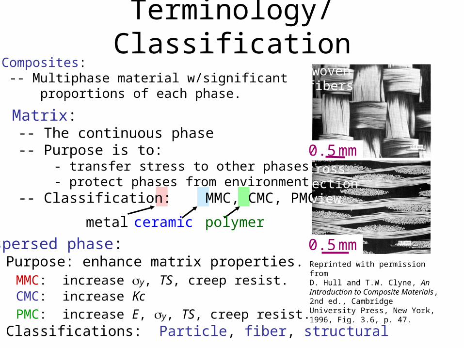
• Composites: -- Multiphase material w/significant proportions of each phase.
• Dispersed phase: -- Purpose: enhance matrix properties. MMC: increase y, TS, creep resist. CMC: increase Kc
PMC: increase E, y, TS, creep resist. -- Classifications: Particle, fiber, structural
• Matrix: -- The continuous phase -- Purpose is to: - transfer stress to other phases - protect phases from environment -- Classification: MMC, CMC, PMC
metal ceramic polymer
Reprinted with permission fromD. Hull and T.W. Clyne, An Introduction to Composite Materials, 2nd ed., Cambridge University Press, New York, 1996, Fig. 3.6, p. 47.
Terminology/Classificationwoven fibers
cross section view
0.5mm
0.5mm
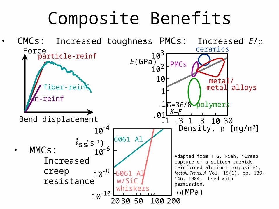
• CMCs: Increased toughness
Composite Benefits
fiber-reinf
un-reinf
particle-reinfForce
Bend displacement
• PMCs: Increased E/
E(GPa)
G=3E/8K=E
Density, [mg/m3].1 .3 1 3 10 30
.01
.1
1
10102
103
metal/ metal alloys
polymers
PMCs
ceramics
Adapted from T.G. Nieh, "Creep rupture of a silicon-carbide reinforced aluminum composite", Metall. Trans. A Vol. 15(1), pp. 139-146, 1984. Used with permission.
• MMCs: Increased creep resistance
20 30 50 100 20010-10
10-8
10-6
10-4
6061 Al
6061 Al w/SiC whiskers (MPa)
ss (s-1)
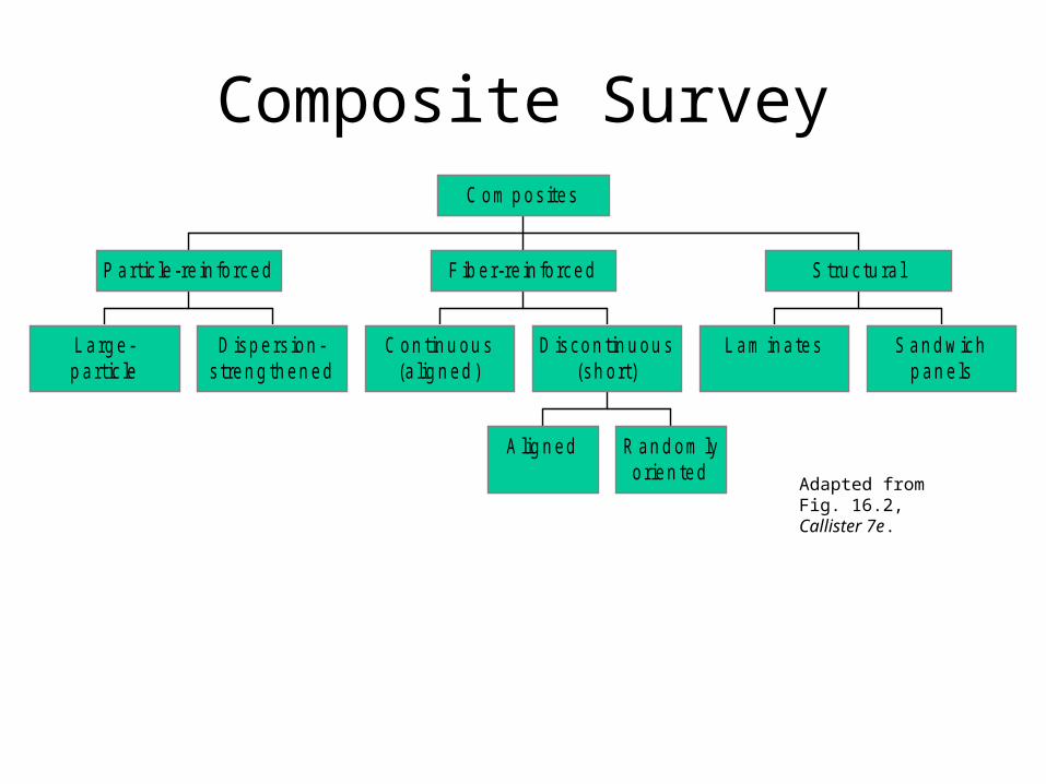
Composite Survey
L arg e-p artic le
D isp ers ion -s tren g th en ed
P artic le -re in fo rced
C on tin u ou s(a lig n ed )
A lig n ed R an d om lyorien ted
D iscon tin u ou s(sh ort)
F ib er-re in fo rced
L am in a tes S an d w ichp an e ls
S tru c tu ra l
C om p os ites
Adapted from Fig. 16.2, Callister 7e.
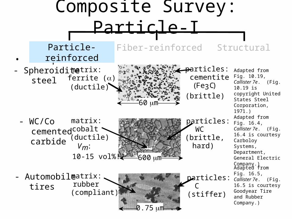
Composite Survey: Particle-I
• Examples:Adapted from Fig. 10.19, Callister 7e. (Fig. 10.19 is copyright United States Steel Corporation, 1971.)
- Spheroidite steel
matrix: ferrite ()(ductile)
particles: cementite (Fe3C)
(brittle)60 m
Adapted from Fig. 16.4, Callister 7e. (Fig. 16.4 is courtesy Carboloy Systems, Department, General Electric Company.)
- WC/Co cemented carbide
matrix: cobalt (ductile)
particles: WC (brittle, hard)Vm:
10-15 vol%! 600 mAdapted from Fig. 16.5, Callister 7e. (Fig. 16.5 is courtesy Goodyear Tire and Rubber Company.)
- Automobile tires
matrix: rubber (compliant)
particles: C (stiffer)
0.75 m
Particle-reinforced Fiber-reinforced Structural
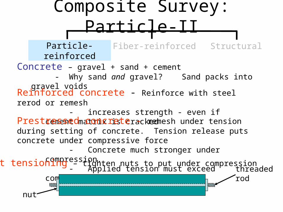
Composite Survey: Particle-II
Concrete – gravel + sand + cement - Why sand and gravel? Sand packs into gravel voids
Reinforced concrete - Reinforce with steel rerod or remesh - increases strength - even if cement matrix is cracked
Prestressed concrete - remesh under tension during setting of concrete. Tension release puts concrete under compressive force
- Concrete much stronger under compression. - Applied tension must exceed compressive force
Particle-reinforced Fiber-reinforced Structural
threadedrod
nut
Post tensioning – tighten nuts to put under compression
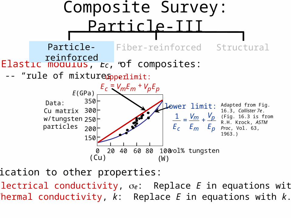
• Elastic modulus, Ec, of composites: -- “rule of mixtures”.
• Application to other properties: -- Electrical conductivity, e: Replace E in equations with e. -- Thermal conductivity, k: Replace E in equations with k.
Adapted from Fig. 16.3, Callister 7e. (Fig. 16.3 is from R.H. Krock, ASTM Proc, Vol. 63, 1963.)
Composite Survey: Particle-III
lower limit:1
Ec= Vm
Em+
Vp
Ep
c m m
upper limit:E = V E + VpEp
Particle-reinforced Fiber-reinforced Structural
Data: Cu matrix w/tungsten particles
0 20 40 60 80 100
150
200
250
300
350
vol% tungsten
E(GPa)
(Cu) (W)
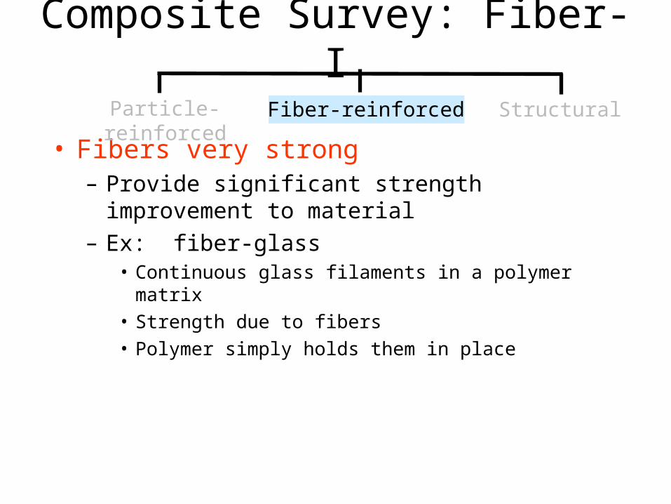
Composite Survey: Fiber-I
• Fibers very strong– Provide significant strength improvement to
material– Ex: fiber-glass
• Continuous glass filaments in a polymer matrix• Strength due to fibers• Polymer simply holds them in place
Particle-reinforced Fiber-reinforced Structural
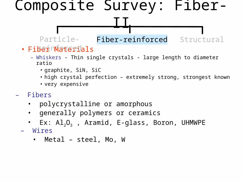
Composite Survey: Fiber-II
• Fiber Materials– Whiskers - Thin single crystals - large length to diameter ratio
• graphite, SiN, SiC• high crystal perfection – extremely strong, strongest known• very expensive
Particle-reinforced Fiber-reinforced Structural
– Fibers• polycrystalline or amorphous• generally polymers or ceramics• Ex: Al2O3 , Aramid, E-glass, Boron, UHMWPE
– Wires• Metal – steel, Mo, W
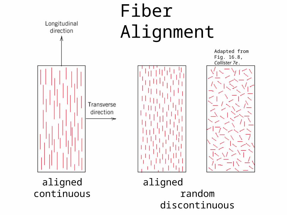
Fiber Alignment
alignedcontinuous
aligned randomdiscontinuous
Adapted from Fig. 16.8, Callister 7e.
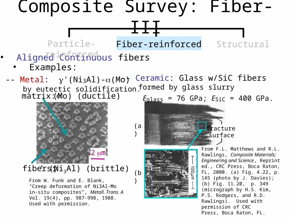
• Aligned Continuous fibers• Examples:
From W. Funk and E. Blank, “Creep deformation of Ni3Al-Mo in-situ composites", Metall. Trans. A Vol. 19(4), pp. 987-998, 1988. Used with permission.
-- Metal: '(Ni3Al)-(Mo) by eutectic solidification.
Composite Survey: Fiber-IIIParticle-reinforced Fiber-reinforced Structural
matrix: (Mo) (ductile)
fibers: ’ (Ni3Al) (brittle)
2 m
-- Ceramic: Glass w/SiC fibers formed by glass slurry
Eglass = 76 GPa; ESiC = 400 GPa.
(a)
(b)
fracture surface
From F.L. Matthews and R.L. Rawlings, Composite Materials; Engineering and Science, Reprint ed., CRC Press, Boca Raton, FL, 2000. (a) Fig. 4.22, p. 145 (photo by J. Davies); (b) Fig. 11.20, p. 349 (micrograph by H.S. Kim, P.S. Rodgers, and R.D. Rawlings). Used with permission of CRCPress, Boca Raton, FL.
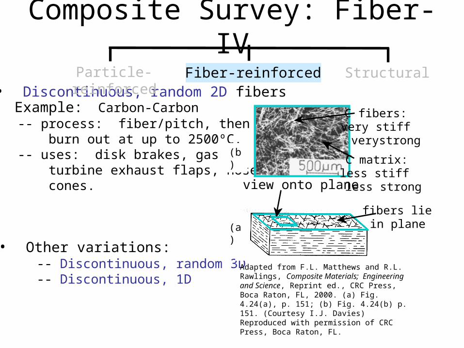
• Discontinuous, random 2D fibers• Example: Carbon-Carbon -- process: fiber/pitch, then burn out at up to 2500ºC. -- uses: disk brakes, gas turbine exhaust flaps, nose cones.
• Other variations: -- Discontinuous, random 3D -- Discontinuous, 1D
Adapted from F.L. Matthews and R.L. Rawlings, Composite Materials; Engineering and Science, Reprint ed., CRC Press, Boca Raton, FL, 2000. (a) Fig. 4.24(a), p. 151; (b) Fig. 4.24(b) p. 151. (Courtesy I.J. Davies) Reproduced with permission of CRC Press, Boca Raton, FL.
Composite Survey: Fiber-IV
Particle-reinforced Fiber-reinforced Structural
(b)
fibers lie in plane
view onto plane
C fibers: very stiff very strong
C matrix: less stiff less strong
(a)
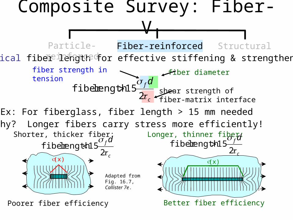
• Critical fiber length for effective stiffening & strengthening:
• Ex: For fiberglass, fiber length > 15 mm needed
Composite Survey: Fiber-V
Particle-reinforced Fiber-reinforced Structural
c
f d
2
15lengthfiber
fiber diameter
shear strength offiber-matrix interface
fiber strength in tension
• Why? Longer fibers carry stress more efficiently!Shorter, thicker fiber:
c
f d
2
15lengthfiber Longer, thinner fiber:
Poorer fiber efficiency
Adapted from Fig. 16.7, Callister 7e.
c
f d
2
15lengthfiber
Better fiber efficiency
(x) (x)
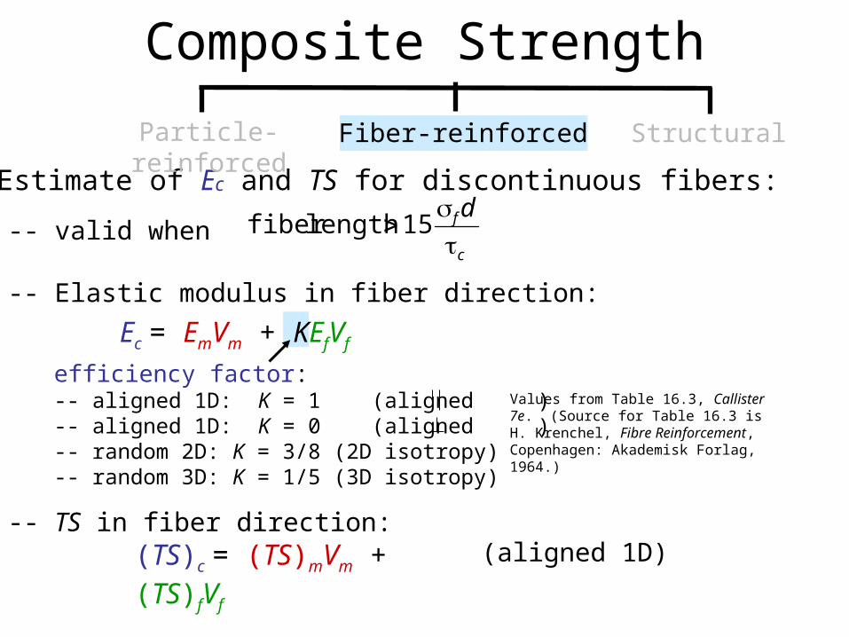
• Estimate of Ec and TS for discontinuous fibers:
-- valid when
-- Elastic modulus in fiber direction:
-- TS in fiber direction:
efficiency factor:-- aligned 1D: K = 1 (aligned )-- aligned 1D: K = 0 (aligned )-- random 2D: K = 3/8 (2D isotropy)-- random 3D: K = 1/5 (3D isotropy)
(aligned 1D)
Values from Table 16.3, Callister 7e. (Source for Table 16.3 is H. Krenchel, Fibre Reinforcement, Copenhagen: Akademisk Forlag, 1964.)
Composite Strength
c
f d
15length fiber
Particle-reinforced Fiber-reinforced Structural
(TS)c = (TS)mVm + (TS)fVf
Ec = EmVm + KEfVf
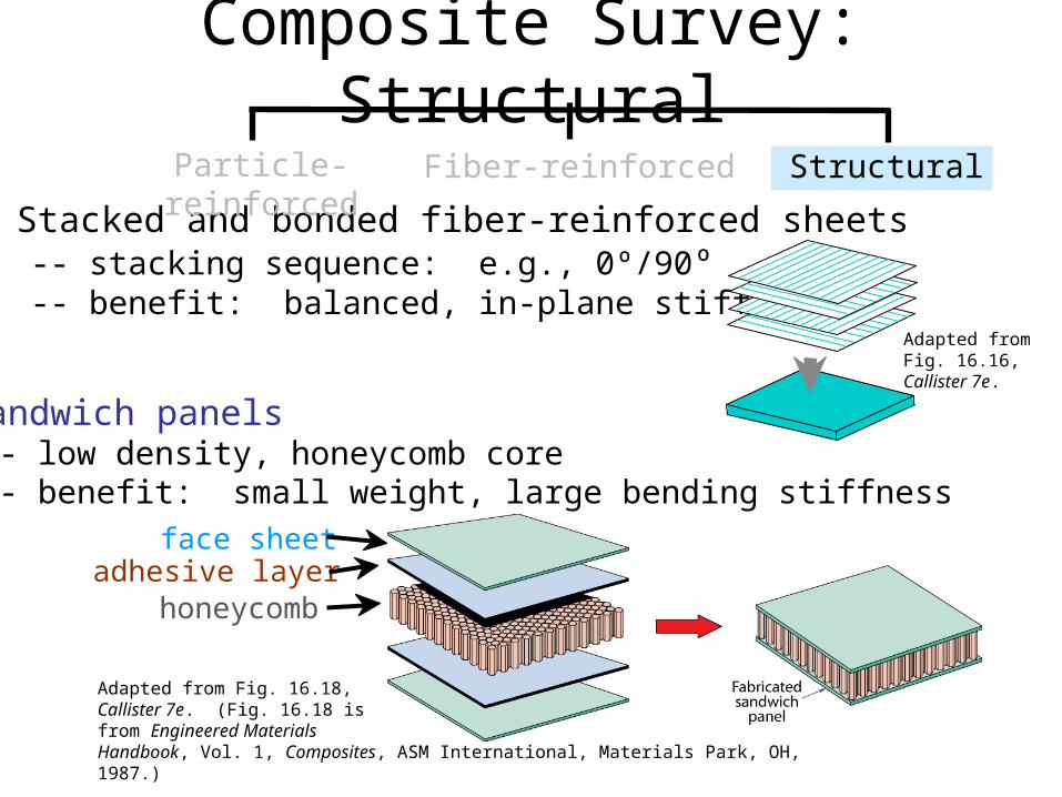
• Stacked and bonded fiber-reinforced sheets -- stacking sequence: e.g., 0º/90º -- benefit: balanced, in-plane stiffness
Adapted from Fig. 16.16, Callister 7e.
Composite Survey: Structural
Particle-reinforced Fiber-reinforced Structural
• Sandwich panels -- low density, honeycomb core -- benefit: small weight, large bending stiffness
honeycombadhesive layer
face sheet
Adapted from Fig. 16.18,Callister 7e. (Fig. 16.18 isfrom Engineered MaterialsHandbook, Vol. 1, Composites, ASM International, Materials Park, OH, 1987.)


![Electrical properties of fiber and carbon nanotube …...investigated as possible reinforcing materials in polymer based composites [2]. CNTs have been shown to possess many desirable](https://img.pdfslide.net/doc/110x75/5ec77b536f970114f16443dc/electrical-properties-of-fiber-and-carbon-nanotube-investigated-as-possible.jpg)